EP1818492A2 - Drive assembly for motorised actuation of a functional element in a motor vehicle - Google Patents
Drive assembly for motorised actuation of a functional element in a motor vehicle Download PDFInfo
- Publication number
- EP1818492A2 EP1818492A2 EP06021402A EP06021402A EP1818492A2 EP 1818492 A2 EP1818492 A2 EP 1818492A2 EP 06021402 A EP06021402 A EP 06021402A EP 06021402 A EP06021402 A EP 06021402A EP 1818492 A2 EP1818492 A2 EP 1818492A2
- Authority
- EP
- European Patent Office
- Prior art keywords
- spindle
- thread
- drive
- spindle nut
- pairing
- Prior art date
- Legal status (The legal status is an assumption and is not a legal conclusion. Google has not performed a legal analysis and makes no representation as to the accuracy of the status listed.)
- Withdrawn
Links
Images


Classifications
-
- F—MECHANICAL ENGINEERING; LIGHTING; HEATING; WEAPONS; BLASTING
- F16—ENGINEERING ELEMENTS AND UNITS; GENERAL MEASURES FOR PRODUCING AND MAINTAINING EFFECTIVE FUNCTIONING OF MACHINES OR INSTALLATIONS; THERMAL INSULATION IN GENERAL
- F16H—GEARING
- F16H25/00—Gearings comprising primarily only cams, cam-followers and screw-and-nut mechanisms
- F16H25/18—Gearings comprising primarily only cams, cam-followers and screw-and-nut mechanisms for conveying or interconverting oscillating or reciprocating motions
- F16H25/20—Screw mechanisms
- F16H25/2056—Telescopic screws with at least three screw members in coaxial arrangement
-
- E—FIXED CONSTRUCTIONS
- E05—LOCKS; KEYS; WINDOW OR DOOR FITTINGS; SAFES
- E05F—DEVICES FOR MOVING WINGS INTO OPEN OR CLOSED POSITION; CHECKS FOR WINGS; WING FITTINGS NOT OTHERWISE PROVIDED FOR, CONCERNED WITH THE FUNCTIONING OF THE WING
- E05F15/00—Power-operated mechanisms for wings
- E05F15/60—Power-operated mechanisms for wings using electrical actuators
- E05F15/603—Power-operated mechanisms for wings using electrical actuators using rotary electromotors
- E05F15/611—Power-operated mechanisms for wings using electrical actuators using rotary electromotors for swinging wings
- E05F15/616—Power-operated mechanisms for wings using electrical actuators using rotary electromotors for swinging wings operated by push-pull mechanisms
- E05F15/622—Power-operated mechanisms for wings using electrical actuators using rotary electromotors for swinging wings operated by push-pull mechanisms using screw-and-nut mechanisms
-
- E—FIXED CONSTRUCTIONS
- E05—LOCKS; KEYS; WINDOW OR DOOR FITTINGS; SAFES
- E05Y—INDEXING SCHEME RELATING TO HINGES OR OTHER SUSPENSION DEVICES FOR DOORS, WINDOWS OR WINGS AND DEVICES FOR MOVING WINGS INTO OPEN OR CLOSED POSITION, CHECKS FOR WINGS AND WING FITTINGS NOT OTHERWISE PROVIDED FOR, CONCERNED WITH THE FUNCTIONING OF THE WING
- E05Y2800/00—Details, accessories and auxiliary operations not otherwise provided for
- E05Y2800/10—Additional functions
- E05Y2800/122—Telescopic action
-
- E—FIXED CONSTRUCTIONS
- E05—LOCKS; KEYS; WINDOW OR DOOR FITTINGS; SAFES
- E05Y—INDEXING SCHEME RELATING TO HINGES OR OTHER SUSPENSION DEVICES FOR DOORS, WINDOWS OR WINGS AND DEVICES FOR MOVING WINGS INTO OPEN OR CLOSED POSITION, CHECKS FOR WINGS AND WING FITTINGS NOT OTHERWISE PROVIDED FOR, CONCERNED WITH THE FUNCTIONING OF THE WING
- E05Y2900/00—Application of doors, windows, wings or fittings thereof
- E05Y2900/50—Application of doors, windows, wings or fittings thereof for vehicles
- E05Y2900/53—Application of doors, windows, wings or fittings thereof for vehicles characterised by the type of wing
- E05Y2900/546—Tailgates
-
- Y—GENERAL TAGGING OF NEW TECHNOLOGICAL DEVELOPMENTS; GENERAL TAGGING OF CROSS-SECTIONAL TECHNOLOGIES SPANNING OVER SEVERAL SECTIONS OF THE IPC; TECHNICAL SUBJECTS COVERED BY FORMER USPC CROSS-REFERENCE ART COLLECTIONS [XRACs] AND DIGESTS
- Y10—TECHNICAL SUBJECTS COVERED BY FORMER USPC
- Y10T—TECHNICAL SUBJECTS COVERED BY FORMER US CLASSIFICATION
- Y10T74/00—Machine element or mechanism
- Y10T74/18—Mechanical movements
- Y10T74/18568—Reciprocating or oscillating to or from alternating rotary
- Y10T74/18576—Reciprocating or oscillating to or from alternating rotary including screw and nut
- Y10T74/18672—Plural screws in series [e.g., telescoping, etc.]
-
- Y—GENERAL TAGGING OF NEW TECHNOLOGICAL DEVELOPMENTS; GENERAL TAGGING OF CROSS-SECTIONAL TECHNOLOGIES SPANNING OVER SEVERAL SECTIONS OF THE IPC; TECHNICAL SUBJECTS COVERED BY FORMER USPC CROSS-REFERENCE ART COLLECTIONS [XRACs] AND DIGESTS
- Y10—TECHNICAL SUBJECTS COVERED BY FORMER USPC
- Y10T—TECHNICAL SUBJECTS COVERED BY FORMER US CLASSIFICATION
- Y10T74/00—Machine element or mechanism
- Y10T74/19—Gearing
- Y10T74/19642—Directly cooperating gears
- Y10T74/19698—Spiral
- Y10T74/19702—Screw and nut
- Y10T74/19744—Rolling element engaging thread
Definitions
- the invention relates to a drive arrangement for the motorized actuation of a functional element in a motor vehicle having the features of the preamble of claim 1 and of claim 13.
- the known drive arrangement shows a drive arrangement for the motorized actuation of the tailgate of a motor vehicle.
- the drive assembly has two drives, which drive-technically attack on the two side edges of the tailgate.
- the drives each have a drive motor and a spindle spindle nut transmission connected downstream of the drive motor.
- the spindle-spindle nut transmission here, as usual, a spindle with an external thread, which runs in the internal thread of a spindle nut.
- the spindle-spindle nut gear can be adjusted between a retracted state and a solid state.
- a linear drive movement namely a movement of the spindle nut parallel to the spindle axis, can hereby be realized comparatively easily.
- a disadvantage of the known drive arrangement is the fact that the spindle-spindle nut transmission in the retracted state has a considerable length. This is because the length of the spindle must be at least equal to the length of the desired feed path. This costs installation space in the interior of the motor vehicle, which is generally tight, The large extent of the drive assembly is also problematic in terms of aesthetics.
- each tailgate of a motor vehicle has a very specific closing and ⁇ ffhuungs characterizing. This means that the force required to close or open the flap changed over the entire closing or opening movement seen. For example, it may be that initially a particularly high force is necessary to open the tailgate of a motor vehicle, if any existing gas spring support the opening movement. But it may also be that such gas pressure dampers are not provided, so that the force required for the opening movement force at a maximum fully open flap is maximum.
- the interpretation of the spindle-spindle nut transmission on the one hand and the drive motor on the other hand therefore represents a compromise in the known drive assembly at best. This compromise leads to high costs, since the drive motor is oversized for a considerable part of the adjustment of the tailgate
- the invention is based on the problem, the known drive arrangement to design and further develop such that reduced with little design effort of the required space and the structural design is optimized.
- the external thread of the spindle and the external thread of the telescopic sleeve and the external thread of the telescopic sleeves each form a threaded pairing with an associated internal thread of the telescopic sleeve or the telescopic sleeves or the spindle nut.
- the individual thread pairings in a predetermined order successively through.
- passing through a thread pairing is meant in the present case that one of the external threads rotates relative to the respective associated internal thread, resulting in a drive movement.
- a thread pairing as such thus acts in this sense as a spindle-spindle nut transmission in the usual sense. Due to the telescopic structure, it is such that when passing through a thread pairing, the subsequent thread pairing and the components associated therewith are displaced. Subsequently, the subsequent thread pairing is passed, resulting in an additional drive movement results.
- the different thread pairings have different coefficients of friction, wherein the initially to be traversed thread pairing has a lower coefficient of friction than the then to be traversed thread pairing.
- the thread pairing with the lowest coefficient of friction is passed first.
- the thread pairing blocking this thread pairing such that then the following thread pairing is performed.
- the sequential passage of the thread pairings is utilized in the further preferred embodiment according to a first variant according to claim 9 for an optimal design of the drive assembly.
- the different thread pairings have different thread pitches, so that the result in the sequential passage through the thread pairings different gear stages are realized.
- Claim 9 provides in a second variant that the thread pitches of the thread pairings on the closing and opening characteristics of the functional element, in particular the Flap of the motor vehicle, are tuned so that over-dimensioning of the drive motor can be largely avoided.
- the spindle, the drive motor and an optionally existing intermediate gear with the possibly existing coupling along the spindle axis is arranged directly behind one another.
- such an arrangement basically increases the length of the drive.
- this can be accepted since a very considerable reduction in the length of the drive is associated with the telescoping design described above. Overall, this arrangement achieves a high degree of compactness.
- ball thread pairing is meant herein the construction in the manner of a ball screw, in which between the two corresponding threads, here between the external thread of the spindle and the internal thread of the spindle nut, a ball set is provided.
- Particularly advantageous is the fact that hereby a changing during the adjustment of the functional element gear ratio can be realized. As a result, the design of the drive arrangement can be further optimized.
- the motor vehicle shown in Fig. 1 shows a drive assembly for the motor actuation of a functional element 2 in the form of a tailgate with a drive 3.
- the drive 3 is for generating linear drive movements with a drive motor 4 and a drive motor 4 downstream spindle spindle nut transmission fifth fitted.
- the spindle-spindle nut transmission 5 has a spindle 6 with an external thread 6a and a spindle nut 7 with an internal thread 7a.
- the linear drive movement is, as in spindle-spindle nut transmissions basically common, a movement of the spindle nut 7 parallel to the spindle axis. 8
- the information "inside” and “outside” here refer in each case to a radial direction with respect to the spindle axis 8.
- a “telescopic arrangement” is meant that the affected components 6, 7, 9 are arranged concentric with the spindle axis 8, so that they can be nested in the manner of a multi-stage telescopic boom in one another.
- thread pairing is finally meant that the respective external thread 6a, 9b is in threaded engagement with the respectively adjacent internal thread 9a, 7a.
- the functional element 2 can basically be any functional element in a motor vehicle. Examples of this have already been given above.
- the functional element 2 is a flap of a motor vehicle, wherein the term "flap" is to be understood comprehensively.
- the tailgate or the boot lid of a motor vehicle but also the side door or the lifting roof of a motor vehicle.
- the functional element 2 is a tailgate 2 of a motor vehicle.
- the tailgate 2 is pivoted on the body of the motor vehicle about a pivot axis 10, whereby a flap opening of the body is closed.
- the drive assembly 1 can here have a single drive 3, which engages drive-technically on a side edge of the tailgate 2.
- the spindle nut 7 is arranged in a spindle nut housing 14, wherein the second force application point 15 of the spindle spindle nut transmission 5 is arranged on the spindle nut housing 14.
- the spindle nut housing 14 with the force application point 15 is arranged rotationally fixed in the installed state. In the generation of drive movements by the drive motor 4 takes place a linear relative movement of the two force application points 13, 15 to each other.
- the force application points 13, 15 are fixed in the installed state on the tailgate 2 on the one hand and on the body of the motor vehicle on the other. It can be seen from the illustrations in FIGS. 2 and 3 that the spindle nut housing 14 is arranged to overlap the spindle housing 12, so that the internal components are protected against contamination.
- the internal thread 7a of the spindle nut can basically also be configured as part of the spindle nut housing 14.
- a single telescopic sleeve 9 is provided that the external thread 6a of the spindle 6 in the internal thread 9a of the telescopic sleeve 9 runs and that the Au- ⁇ engewinde 9b of the telescopic sleeve 9 in the internal thread 7a of the spindle nut 7 is running.
- the spindle-spindle nut transmission 5 can in principle be brought from the retracted state shown in FIG. 2 into the extended state shown in FIG. 3 by rotating the spindle 6. It can be seen from the illustration in Fig.
- the telescopic sleeve 9 in the extended state of the spindle-spindle nut transmission 5 is effectively an extension of the external thread 6a of the spindle 6.
- the telescopic sleeve 9 is an extension of the internal thread 7a of the spindle nut 7. This ensures that despite the small length of the spindle-spindle nut transmission 5, a considerable feed path can be realized.
- the individual thread pairings are passed in succession in a predetermined order. It is preferably provided that during the course of a thread pairing the other thread pairing or, the other thread pairings will not go through or will be, so to speak represents a rigid connection or represent.
- the outer thread pairings are traversed by the internal thread pairings in the adjustment of the spindle-spindle nut transmission 5 from the retracted state to the extended state. In particular, starting from the state shown in Fig.
- the different thread pairings have different coefficients of friction, wherein the initially to be traversed thread pairing preferably has a lower coefficient of friction than the then to be traversed thread pairing.
- the different coefficients of friction of the different thread pairings can be realized, for example, by different materials and / or coatings of the components involved, that is to say the spindle 6, the telescopic sleeve 9 or the telescopic sleeves and the spindle nut 7.
- the spindle-spindle nut transmission 5 can be converted by the reverse drive of the spindle 6 again in the retracted state. It is envisaged that the blocking described above between the spindle 6 and the telescopic sleeve 9 leads to a predefined jamming of these two components 6, 9, so that first the external thread 9b of the telescopic sleeve 9 in the internal thread 7a of the spindle nut 7 runs, resulting in a first contraction of the spindle-spindle nut transmission 5.
- the translation is additionally variable within a thread pairing.
- the thread pairing is designed as a ball thread pairing which has a variable thread pitch over its length.
- the spindle 6 is configured by way of example as a ball screw, which cooperates with the telescopic sleeve 9 accordingly.
- the term "ball screw pairing" has been explained in the general part of the description. This is within the thread pairing during the passage of the thread pairing a stepless change of the translation conceivable.
- the spindle-spindle nut gear 5 is further provided with a spring assembly 23 which causes a bias between the spindle housing 12 and the spindle nut housing 14 in the direction of the extended state.
- a spring assembly 23 which causes a bias between the spindle housing 12 and the spindle nut housing 14 in the direction of the extended state.
- a drive arrangement which in turn has a drive 3 with drive motor 4 and downstream spindle spindle nut transmission 5.
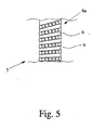
- the spindle-spindle nut transmission 5 has here, unlike the above, no telescopic sleeve, so that the external thread 6a of the spindle 6 with the internal thread 7b of the spindle nut 7 forms a thread pairing. It is envisaged that this thread pairing is a ball thread pairing which has a varying pitch over its length.
- the functional principle is again shown in FIG. 5, wherein the local reference numeral 9 is to be replaced by the reference numeral 7.
- the associated advantage of achieving a continuously variable transmission when passing through the thread pairing has been explained above in the description of the individual gear stages. It may altogether on the above statements, unless you refer to the specific design of the telescopic sleeve 9, referenced.
Abstract
Description
Die Erfindung betrifft eine Antriebsanordnung zur motorischen Betätigung eines Funktionselements in einem Kraftfahrzeug mit den Merkmalen des Oberbegriffs von Anspruch 1 und von Anspruch 13.The invention relates to a drive arrangement for the motorized actuation of a functional element in a motor vehicle having the features of the preamble of
Im Rahmen der Komforterhöhung bei Kraftfahrzeugen kommt der in Rede stehenden Antriebsanordnung zunehmende Bedeutung zu. Die motorisch verstellbaren Funktionselemente sind hier beispielsweise Klappen, insbesondere Heckklappen, Heckdeckel, Seitentüren oder Hubdächer, Fahrzeugsitze o. dgl. Neben hoher Zuverlässigkeit und geringen Kosten spielt die Kompaktheit einer solchen Antriebsanordnung eine wichtige Rolle.As part of the comfort increase in motor vehicles of the drive assembly in question is becoming increasingly important. The motor-adjustable functional elements are here, for example, flaps, especially tailgates, trunk lid, side doors or lifting roofs, vehicle seats o. The like. In addition to high reliability and low cost, the compactness of such a drive arrangement plays an important role.
Die bekannte Antriebsanordnung (
Nachteilig ist bei der bekannten Antriebsanordnung die Tatsache, daß das Spindel-Spindelmutter-Getriebe im eingezogenen Zustand eine beträchtliche Länge aufweist. Dies liegt daran, daß die Länge der Spindel mindestens der Länge des gewünschten Vorschubwegs entsprechen muß. Dies kostet Bauraum im Innenraum des Kraftfahrzeugs, der grundsätzlich knapp bemessen ist, Die große Ausdehnung der Antriebsanordnung ist auch in ästhetischer Hinsicht problematisch.A disadvantage of the known drive arrangement is the fact that the spindle-spindle nut transmission in the retracted state has a considerable length. This is because the length of the spindle must be at least equal to the length of the desired feed path. This costs installation space in the interior of the motor vehicle, which is generally tight, The large extent of the drive assembly is also problematic in terms of aesthetics.
Ferner ist zu berücksichtigen, daß jede Heckklappe eines Kraftfahrzeugs eine ganz bestimmte Schließ- und Öffiiungscharakteristik aufweist. Dies bedeutet, daß sich der zum Schließen bzw. zum Öffnen der Klappe erforderliche Kraftaufwand über die gesamte Schließ- bzw. Öffnungsbewegung gesehen verändert. Beispielsweise kann es sein, daß zum Öffnen der Heckklappe eines Kraftfahrzeugs anfangs eine besonders hohe Kraft notwendig ist, bis gegebenenfalls vorhandene Gasdruckdämpfer die Öffnungsbewegung unterstützen. Es kann aber auch sein, daß derartige Gasdruckdämpfer nicht vorgesehen sind, so daß der für die Öffnungsbewegung erforderliche Kraftaufwand bei nahezu voll geöffneter Klappe maximal ist. Die Auslegung des Spindel-Spindelmutter-Getriebes einerseits und des Antriebsmotors andererseits stellt daher bei der bekannten Antriebsanordnung allenfalls einen Kompromiß dar. Dieser Kompromiß führt zu hohen Kosten, da der Antriebsmotor für einen beträchtlichen Teil der Verstellbewegung der Heckklappe überdimensioniert istIt should also be noted that each tailgate of a motor vehicle has a very specific closing and Öffhuungscharakteristik. This means that the force required to close or open the flap changed over the entire closing or opening movement seen. For example, it may be that initially a particularly high force is necessary to open the tailgate of a motor vehicle, if any existing gas spring support the opening movement. But it may also be that such gas pressure dampers are not provided, so that the force required for the opening movement force at a maximum fully open flap is maximum. The interpretation of the spindle-spindle nut transmission on the one hand and the drive motor on the other hand therefore represents a compromise in the known drive assembly at best. This compromise leads to high costs, since the drive motor is oversized for a considerable part of the adjustment of the tailgate
Der Erfindung liegt das Problem zugrunde, die bekannte Antriebsanordnung derart auszugestalten und weiterzubilden, daß mit geringem konstruktivem Aufwand der erforderliche Bauraum reduziert und die konstruktive Auslegung optimiert wird.The invention is based on the problem, the known drive arrangement to design and further develop such that reduced with little design effort of the required space and the structural design is optimized.
Das obige Problem wird bei einer Antriebsanordnung mit den Merkmalen des Oberbegriffs von Anspruch 1 zunächst durch die Merkmale des kennzeichnenden Teils von Anspruch 1 gelöst.The above problem is solved in a drive assembly having the features of the preamble of
Wesentlich ist die Überlegung, das Prinzip eines mehrstufigen Teleskopauslegers auf das Spindel-Spindelmutter-Getriebe der in Rede stehenden Antriebsanordnung anzuwenden. Dabei wird zwischen die Spindel und die Spindelmutter mindestens eine Teleskophülse geschaltet, durch die das Außengewinde der Spindel gewissermaßen verlängerbar ist. Man könnte auch andersherum sagen, daß die Länge des Innengewindes der Spindelmutter durch die Teleskophülse bzw. die Teleskophülsen verlängerbar istIt is essential to apply the principle of a multi-stage telescopic boom on the spindle-spindle nut transmission of the drive assembly in question. In this case, at least one telescopic sleeve is connected between the spindle and the spindle nut, through which the external thread of the spindle is effectively extended. One could say the other way around that the length of the internal thread of the spindle nut by the telescopic sleeve or telescopic sleeves is extended
Mit der obigen Integration der Teleskophülse bzw. der Teleskophülsen in das Spindel-Spindelmutter-Getriebe wird im Ergebnis eine Reduzierung der Länge des Spindel-Spindelmutter-Getriebes im eingezogenen Zustand bei unverändert großem Vorschubweg gewährleistet.With the above integration of the telescopic sleeve or telescopic sleeves in the spindle-spindle nut transmission is the result of a reduction in length ensures the spindle-spindle nut transmission in the retracted state with unchanged feed path.
Das Außengewinde der Spindel sowie das Außengewinde der Teleskophülse bzw. die Außengewinde der Teleskophülsen bilden jeweils eine Gewindepaarung mit einem zugeordneten Innengewinde der Teleskophülse bzw. der Teleskophülsen oder der Spindelmutter. Bei der bevorzugten Ausgestaltung gemäß Anspruch 6 werden bei der motorischen Verstellung der Spindel die einzelnen Gewindepaarungen in einer vorbestimmten Reihenfolge nacheinander durchlaufen. Mit "Durchlaufen einer Gewindepaarung" ist vorliegend gemeint, daß eines der Außengewinde relativ zu dem jeweils zugeordneten Innengewinde rotiert, woraus eine Antriebsbewegung resultiert. Eine Gewindepaarung als solche wirkt in diesem Sinne also wie ein Spindel-Spindelmutter-Getriebe im üblichen Sinne. Durch den teleskopartigen Aufbau ist es so, daß beim Durchlaufen der einen Gewindepaarung die nachfolgende Gewindepaarung und die damit verbundenen Komponenten verschoben werden. Anschließend wird die nachfolgende Gewindepaarung durchlaufen, woraus eine zusätzliche Antriebsbewegung resultiert.The external thread of the spindle and the external thread of the telescopic sleeve and the external thread of the telescopic sleeves each form a threaded pairing with an associated internal thread of the telescopic sleeve or the telescopic sleeves or the spindle nut. In the preferred embodiment according to
Bei der besonders bevorzugten Ausgestaltung gemäß Anspruch 7 weisen die verschiedenen Gewindepaarungen unterschiedliche Reibwerte auf, wobei die anfangs zu durchlaufende Gewindepaarung einen geringeren Reibwert aufweist als die anschließend zu durchlaufende Gewindepaarung. Beim Antrieb der Spindel wird die Gewindepaarung mit dem geringsten Reibwert zuerst durchlaufen. Bei der bevorzugten Ausgestaltung gemäß Anspruch 8 erfolgt nach dem Durchlaufen einer Gewindepaarung eine Blockierung dieser Gewindepaarung derart, daß anschließend die folgende Gewindepaarung durchlaufen wird.In the particularly preferred embodiment according to
Das sequentielle Durchlaufen der Gewindepaarungen wird bei der weiter bevorzugten Ausgestaltung gemäß einer ersten Variante gemäß Anspruch 9 für eine optimale Auslegung der Antriebsanordnung ausgenutzt. Hier ist es vorgesehen, daß die verschiedenen Gewindepaarungen unterschiedliche Gewindesteigungen aufweisen, so daß im Ergebnis beim sequentiellen Durchlaufen der Gewindepaarungen unterschiedliche Getriebestufen realisiert sind. Anspruch 9 sieht in einer zweiten Variante vor, daß die Gewindesteigungen der Gewindepaarungen auf die Schließ- und Öffnungscharakteristik des Funktionselements, insbesondere der Klappe des Kraftfahrzeugs, abgestimmt sind, so daß eine Überdimensionierung des Antriebsmotors weitgehend vermieden werden kann.The sequential passage of the thread pairings is utilized in the further preferred embodiment according to a first variant according to
Besonders kompakt gestaltet sich die bevorzugte Ausgestaltung gemäß Anspruch 12. Hier ist die Spindel, der Antriebsmotor und ein gegebenenfalls vorhandenes Zwischengetriebe mit der gegebenenfalls vorhandenen Kupplung entlang der Spindelachse gesehen unmittelbar hintereinander angeordnet. Eine solche Anordnung erhöht zwar grundsätzlich die Länge des Antriebs. Dies kann allerdings in Kauf genommen werden, da mit der oben beschriebenen, teleskopartigen Ausgestaltung eine ganz erhebliche Reduzierung der Länge des Antriebs verbunden ist. Insgesamt erreicht man mit dieser Anordnung eine hohe Kompaktheit.Particularly compact designed the preferred embodiment according to
Nach einer weiteren Lehre, der eigenständige Bedeutung zukommt, wird das obige Problem bei einer Antriebsanordnung mit den Merkmalen des Oberbegriffs von Anspruch 13 durch die Merkmale des kennzeichnenden Teils von Anspruch 13 gelöst.According to another teaching of independent significance, the above problem is solved in a drive assembly having the features of the preamble of
Wesentlich ist die Erkenntnis, daß eine Kugelgewindepaarung geeignet ist, um eine über die Länge der Kugelgewindepaarung sich verändernde Gewindesteigung zu realisieren. Mit "Kugelgewindepaarung" ist vorliegend der Aufbau nach Art einer Kugelgewindespindel gemeint, bei dem zwischen den beiden korrespondierenden Gewinden, hier zwischen dem Außengewinde der Spindel und dem Innengewinde der Spindelmutter, ein Kugelsatz vorgesehen ist. Vorteilhaft ist insbesondere die Tatsache, daß hiermit eine während der Verstellung des Funktionselements sich stetig verändernde Getriebeübersetzung realisiert werden kann. Hierdurch läßt sich die Auslegung der Antriebsanordnung weiter optimieren.It is essential to recognize that a ball thread pairing is suitable for realizing a thread pitch that changes over the length of the ball thread pairing. By "ball thread pairing" is meant herein the construction in the manner of a ball screw, in which between the two corresponding threads, here between the external thread of the spindle and the internal thread of the spindle nut, a ball set is provided. Particularly advantageous is the fact that hereby a changing during the adjustment of the functional element gear ratio can be realized. As a result, the design of the drive arrangement can be further optimized.
Im folgenden wird die Erfindung anhand eines Ausführungsbeispiels näher erläutert. In der Zeichnung zeigt
- Fig. 1
- den hinteren Teil eines Kraftfahrzeugs mit einer erfindungsgemäßen Antriebsanordnung in einer Seitenansicht,
- Fig. 2
- den Antrieb einer erfindungsgemäßen Antriebsanordnung bei im eingezogenen Zustand befindlichem Spindel-Spindelmutter-Getriebe in einer teilweise geschnittenen Darstellung,
- Fig. 3
- die Darstellung gemäß Fig. 2 bei im vollständig ausgezogenen Zustand befindlichem Spindel-Spindelmutter-Getriebe,
- Fig. 4
- in ganz schematischer Darstellung die wesentlichen Komponenten eines Spindel-Spindelmutter-Getriebes einer erfindungsgemäßen Antriebsanordnung gemäß einer weiteren Ausführungsform und
- Fig. 5
- in ganz schematischer Darstellung eine als Kugelgewindepaarung ausgestaltete Gewindepaarung einer erfindungsgemäßen Antriebs-anordnung gemäß einer weiteren Ausführungsform.
- Fig. 1
- the rear part of a motor vehicle with a drive assembly according to the invention in a side view,
- Fig. 2
- the drive of a drive assembly according to the invention in the state in the retracted spindle spindle nut gear in a partially sectioned view,
- Fig. 3
- 2 in the case of the fully extended state spindle spindle nut transmission,
- Fig. 4
- in a very schematic representation of the essential components of a spindle-spindle nut transmission of a drive assembly according to the invention according to another embodiment and
- Fig. 5
- in a very schematic representation configured as a ball thread pair thread pairing of a drive arrangement according to the invention according to a further embodiment.
Das in Fig. 1 dargestellte Kraftfahrzeug zeigt eine Antriebsanordnung zur motorischen Betätigung eines Funktionselements 2 in Form einer Heckklappe mit einem Antrieb 3. Der Antrieb 3 ist zur Erzeugung von linearen Antriebsbewegungen mit einem Antriebsmotor 4 und einem dem Antriebsmotor 4 nachgeschalteten Spindel-Spindelmutter-Getriebe 5 ausgestattet. Es ist der Darstellung in Fig. 2 zu entnehmen, daß das Spindel-Spindelmutter-Getriebe 5 eine Spindel 6 mit einem Außengewinde 6a und einer Spindelmutter 7 mit einem Innengewinde 7a aufweist. Die lineare Antriebsbewegung ist, wie bei Spindel-Spindelmutter-Getrieben grundsätzlich üblich, eine Bewegung der Spindelmutter 7 parallel zur Spindelachse 8.The motor vehicle shown in Fig. 1 shows a drive assembly for the motor actuation of a
Bei dem Spindel-Spindelmutter-Getriebe 5 handelt es sich gegenüber bekannten Spindel-Spindelmutter-Getrieben insoweit um eine modifizierte Anordnung, als hier mindestens eine Teleskophülse 9 mit einem Innengewinde 9a und einem Außengewinde 9b vorgesehen ist, die zwischen die Spindel 6 und die Spindelmutter 7 geschaltet ist. Dies ist einer Zusammenschau der Fig. 2 und 3 zu entnehmen. Hier ist es so, daß innen die Spindel 6, weiter außen die Teleskophülse 9 und ganz außen die Spindelmutter 7 teleskopartig und ineinanderschraubbar angeordnet sind, so daß jedes Außengewinde 6a, 9b mit dem jeweils benachbarten Innengewinde 9a, 7a eine Gewindepaarung bildet. Die Angaben "innen" und "außen" beziehen sich hier jeweils auf eine hinsichtlich der Spindelachse 8 radiale Richtung. Mit einer "teleskopartigen Anordnung" ist gemeint, daß die betroffenen Komponenten 6, 7, 9 konzentrisch zur Spindelachse 8 angeordnet sind, so daß sie nach Art eines mehrstufigen teleskopartigen Auslegers ineinander geschachtelt werden können. Mit "Gewindepaarung" ist schließlich gemeint, daß das jeweilige Außengewinde 6a, 9b mit dem jeweils benachbarten Innengewinde 9a, 7a in Gewindeeingriff steht. Die Funktionsweise dieses modifizierten Spindel-Spindelmutter-Getriebes 5 wird weiter unten noch im Detail erläutert. Bei dem Funktionselement 2 kann es sich grundsätzlich um irgendein Funktionselement in einem Kraftfahrzeug handeln. Beispiele hierfür wurden weiter oben bereits gegeben. Vorzugsweise handelt es sich bei dem Funktionselement 2 um eine Klappe eines Kraftfahrzeugs, wobei der Begriff "Klappe" umfassend zu verstehen ist Hierunter fällt vorliegend die Heckklappe oder der Heckdeckel eines Kraftfahrzeugs, aber auch die Seitentür oder das Hubdach eines Kraftfahrzeugs.In the spindle-
Bei dem dargestellten und insoweit bevorzugten Ausführungsbeispiel handelt es sich bei dem Funktionselement 2 um eine Heckklappe 2 eines Kraftfahrzeugs. Die Heckklappe 2 ist an der Karosserie des Kraftfahrzeugs um eine Schwenkachse 10 schwenkbar angelenkt, wodurch eine Klappenöffnung der Karosserie verschließbar ist. Die Antriebsanordnung 1 kann hier einen einzigen Antrieb 3 aufweisen, der an einem Seitenrand der Heckklappe 2 antriebstechnisch angreift. In besonders bevorzugter Ausgestaltung ist es jedoch so, daß zwei Antriebe 3 vorgesehen sind und daß die beiden Antriebe 3 an den beiden Seitenrändern der Heckklappe 2 antriebstechnisch angreifen. Dies ist vor dem Hintergrund eines ungewünschten Verwindens der Heckklappe 2 besonders vorteilhaft.In the illustrated preferred embodiment, the
Bei dem dargestellten und insoweit bevorzugten Ausführungsbeispiel ist die Spindel 6 in einem Lagerbock 11 drehbar gelagert. Der Lagerbock 11 befindet sich in einem Spindelgehäuse 12, an dem ein erster Kraftangriffspunkt 13 des Spindel-Spindelmutter-Getriebes 5 angeordnet ist. Der Lagerbock 11 ist im eingebauten Zustand zusammen mit dem Spindelgehäuse 12 und dem ersten Kraftangriffspunkt 13 verdrehfest angeordnet. Die Spindel 6 ist hier antriebstechnisch mit dem Antriebsmotor 4 gekoppelt. Grundsätzlich kann es aber auch vorgesehen sein, daß die Spindelmutter 7 antriebstechnisch mit dem Antriebsmotor 4 gekoppelt ist, wobei die Spindel 6 dann verdrehfest angeordnet ist.In the illustrated and insofar preferred embodiment, the
Die Spindelmutter 7 ist in einem Spindelmuttergehäuse 14 angeordnet, wobei am Spindelmuttergehäuse 14 der zweite Kraftangriffspunkt 15 des Spindel-Spindelmutter-Getriebes 5 angeordnet ist. Auch das Spindelmuttergehäuse 14 mit dem Kraftangriffspunkt 15 ist im eingebauten Zustand verdrehfest angeordnet. Bei der Erzeugung von Antriebsbewegungen durch den Antriebsmotor 4 erfolgt eine lineare Relativbewegung der beiden Kraftangriffspunkte 13, 15 zueinander. Die Kraftangriffspunkte 13, 15 sind im eingebauten Zustand an der Heckklappe 2 einerseits und an der Karosserie des Kraftfahrzeugs andererseits festgelegt. Es ist den Darstellungen in Fig. 2 und 3 zu entnehmen, daß das Spindelmuttergehäuse 14 zu dem Spindelgehäuse 12 überlappend angeordnet ist, so daß die innenliegenden Komponenten vor Verschmutzung geschützt sind. In diesem Zusammenhang darf darauf hingewiesen werden, daß das Innengewinde 7a der Spindelmutter grundsätzlich auch als Bestandteil des Spindelmuttergehäuses 14 ausgestaltet sein kann.The
Bei dem dargestellten und insoweit bevorzugten Ausführungsbeispiel ist es so, daß eine einzige Teleskophülse 9 vorgesehen ist, daß das Außengewinde 6a der Spindel 6 in dem Innengewinde 9a der Teleskophülse 9 läuft und daß das Au-βengewinde 9b der Teleskophülse 9 in dem Innengewinde 7a der Spindelmutter 7 läuft. Dadurch läßt sich das Spindel-Spindelmutter-Getriebe 5 durch ein Rotieren der Spindel 6 grundsätzlich von dem in Fig. 2 dargestellten, eingezogenen Zustand in den in Fig. 3 dargestellten, ausgezogenen Zustand bringen. Es ist der Darstellung in Fig. 3 zu entnehmen, daß die Teleskophülse 9 im ausgezogenen Zustand des Spindel-Spindelmutter-Getriebes 5 gewissermaßen eine Verlängerung des Außengewindes 6a der Spindel 6 darstellt. Umgekehrt könnte man auch sagen, daß die Teleskophülse 9 eine Verlängerung des Innengewindes 7a der Spindelmutter 7 darstellt. Damit wird gewährleistet, daß trotz der geringen Länge des Spindel-Spindelmutter-Getriebes 5 ein erheblicher Vorschubweg realisierbar ist.In the illustrated and so far preferred embodiment, it is such that a single
In weiter bevorzugter Ausgestaltung kann es auch vorgesehen sein, daß mindestens zwei teleskopartig und ineinanderschraubbar angeordnete Teleskophülsen vorgesehen sind, wobei dann das Außengewinde der Spindel in dem Innengewinde der innenliegenden Teleskophülse läuft und das Außengewinde der außenliegenden Teleskophülse in dem Innengewinde der Spindelmutter läuft. Hiermit ist grundsätzlich eine beliebige Verlängerung des Vorschubwegs möglich, solange die Anforderungen an die Stabilität der Anordnung gewährleistet sind.In a further preferred embodiment, it can also be provided that at least two telescopically and telescopically arranged telescopic sleeves are provided, in which case the external thread of the spindle runs in the internal thread of the inner telescopic sleeve and the external thread of the outer Telescopic sleeve runs in the internal thread of the spindle nut. In principle, any extension of the feed path is possible as long as the requirements for the stability of the arrangement are ensured.
Die Anordnung ist nun so getroffen, daß bei der motorischen Verstellung der Spindel 6 die einzelnen Gewindepaarungen in einer vorbestimmten Reihenfolge nacheinander durchlaufen werden. Dabei ist es vorzugsweise vorgesehen, daß während des Durchlaufens einer Gewindepaarung die andere Gewindepaarung bzw, die anderen Gewindepaarungen nicht durchlaufen wird bzw. werden, also gewissermaßen eine starre Verbindung darstellt bzw. darstellen. Im dargestellten und insoweit bevorzugten Ausführungsbeispiel werden bei der Verstellung des Spindel-Spindelmutter-Getriebes 5 vom eingezogenen Zustand in den ausgezogenen Zustand die außenliegenden Gewindepaarungen nach den innenliegenden Gewindepaarungen durchlaufen. Im einzelnen ist es so, daß ausgehend von dem in Fig. 2 dargestellten, eingezogenen Zustand zunächst das Außengewinde 6a der Spindel 6 im Innengewinde 9a der Teleskophülse 9 läuft, so daß die Teleskophülse 9 und damit die Spindelmutter 7 relativ zum Spindelgehäuse 12 verstellt werden. Nach dem Durchlaufen dieser Gewindepaarung läuft das Außengewinde 9b der Teleskophülse 9 im Innengewinde 7a der Spindelmutter 7, so daß die Spindelmutter 7 relativ zur Teleskophülse 9 und damit weiter relativ zum Spindelgehäuse 12 verstellt wird. Der Übergang vom Durchlaufen der erstgenannten Gewindepaarung zum Durchlaufen der letztgenannten Gewindepaarung wird im folgenden noch näher erläutert.The arrangement is now made such that in the motorized adjustment of the
In besonders bevorzugter Ausgestaltung ist es vorgesehen, daß die verschiedenen Gewindepaarungen unterschiedliche Reibwerte aufweisen, wobei die anfangs zu durchlaufende Gewindepaarung vorzugsweise einen geringeren Reibwert aufweist als die anschließend zu durchlaufende Gewindepaarung. Dies bedeutet, daß ausgehend von dem in Fig. 2 dargestellten, eingezogenen Zustand des Spindel-Spindelmutter-Getriebes 5 zunächst das Außengewinde 6a der Spindel 6 im Innengewinde 9a der Teleskophülse 9 läuft, da der Reibwert zwischen der Spindel 6 und der Teleskophülse 9 geringer ist als der Reibwert zwischen der Teleskophülse 9 und der verdrehfest angeordneten Spindelmutter 7. Selbstverständlich kann dies auch andersherum vorgesehen sein.In a particularly preferred embodiment, it is provided that the different thread pairings have different coefficients of friction, wherein the initially to be traversed thread pairing preferably has a lower coefficient of friction than the then to be traversed thread pairing. This means that starting from the illustrated in Fig. 2, retracted state of the spindle-
Die unterschiedlichen Reibwerte der verschiedenen Gewindepaarungen lassen sich beispielsweise durch unterschiedliche Werkstoffe und/oder Beschichtungen der beteiligten Komponenten, also der Spindel 6, der Teleskophülse 9 bzw. der Teleskophülsen und der Spindelmutter 7 realisieren.The different coefficients of friction of the different thread pairings can be realized, for example, by different materials and / or coatings of the components involved, that is to say the
Besondere Bedeutung kommt nun dem Übergang des Durchlaufens einer Gewindepaarung zum Durchlaufen der nachfolgenden Gewindepaarung zu. In bevorzugter Ausgestaltung ist es vorgesehen, daß nach dem Durchlaufen einer Gewindepaarung der das Außengewinde 6a, 9b dieser Gewindepaarung aufweisende Bestandteil 6, 9 mit dem das Innengewinde 9a, 7a dieser Gewindepaarung aufweisenden Bestandteil 9, 7 in blockierenden Eingriff kommt und daß dadurch die anschließend zu durchlaufende Gewindepaarung durchlaufen wird. Dies ist bei dem dargestellten Ausführungsbeispiel in besonders einfacher Weise realisiert. Hier ist es nämlich so, daß sich das Innengewinde 9a der Teleskophülse 9 ausschließlich über einen kurzen unteren Bereich 16 der Teleskophülse erstreckt und daß der übrige innenliegende Teil der Teleskophülse 9 als Lauffläche 17 für eine an der Spindel 6 angeordnete Lagerbuchse 18 dient. Die Lagerbuchse 18 liegt in Richtung der Spindelachse 8 an einem Absatz 19 an. Die Lauffläche 17 weist einen größeren Durchmesser als der Innendurchmesser des Innengewindes 9a der Teleskophülse 9 auf.Particular importance is now attached to the transition of the passage of a thread pairing for passing through the subsequent thread pairing. In a preferred embodiment, it is provided that after passing through a threaded pair of the
Wird nun ausgehend von dem in Fig. 2 dargestellten Zustand die Spindel 6 angetrieben, so läuft aufgrund der oben beschriebenen Auslegung der Reibwerte der Gewindepaarungen zunächst das Außengewinde 6a der Spindel 6 im Innengewinde 9a der Teleskophülse 9, bis die Lagerbuchse 18 das Innengewinde 9a der Teleskophülse 9 erreicht. Hierdurch kommt die Spindel 6 mit der Teleskophülse 9 in blockierenden Eingriff, so daß bei weiterer Drehung der Spindel 6 die Teleskophülse 9 nunmehr mitgedreht wird. Dies führt schließlich dazu, daß das Außengewinde 9b der Teleskophülse 9 im Innengewinde 7a der Spindelmutter 7 läuft.If, starting from the state shown in FIG. 2, the
Ausgehend von dem in Fig. 3 dargestellten ausgezogenen Zustand läßt sich das Spindel-Spindelmutter-Getriebe 5 durch den umgekehrten Antrieb der Spindel 6 wieder in den eingezogenen Zustand überführen. Dabei ist es vorgesehen, daß die zuvor beschriebene Blockierung zwischen der Spindel 6 und der Teleskophülse 9 auch zu einem vordefinierten Verklemmen dieser beiden Komponenten 6, 9 führt, so daß zunächst das Außengewinde 9b der Teleskophülse 9 im Innengewinde 7a der Spindelmutter 7 läuft, was zu einem ersten Zusammenziehen des Spindel-Spindelmutter-Getriebes 5 führt. Sobald die Teleskophülse 9 mit ihrer Stirnfläche 9c den Anschlag 20 am Spindelmuttergehäuse 14 erreicht, wird die Teleskophülse 9 gegenüber der Spindelmutter 7 blockiert. Bei weiterer Drehung der Spindel 6 wird die oben beschriebene Klemmung zwischen der Spindel 6 und der Teleskophülse 9 überwunden, so daß schließlich das Außengewinde 6a der Spindel 6 im Innengewinde 9a der Teleskophülse 9 läuft und das Spindel-Spindelmutter-Getriebe 5 in den in Fig. 2 dargestellten, eingezogenen Zustand überführt wird.Starting from the extended state shown in Fig. 3, the spindle-
Die oben beschriebene Realisierung des sequentiellen Durchlaufens der Gewindepaarungen stellt eine konstruktiv besonders einfach realisierbare Variante dar. Hier sind auch andere Realisierungsmöglichkeiten denkbar.The above-described realization of the sequential passage of the thread pairings represents a structurally particularly easy-to-implement variant. Other possible implementations are also conceivable here.
Es ist nun zusätzlich erkannt worden, daß das oben beschriebene, sequentielle Durchlaufen von Gewindepaarungen dazu genutzt werden kann, den Antrieb 3 der Antriebsanordnung 1 mit unterschiedlichen Getriebestufen auszustatten. Hierfür ist es vorgesehen, daß die verschiedenen Gewindepaarungen unterschiedliche Gewindesteigungen aufweisen. Dies ist ganz schematisch in Fig. 4 dargestellt. Beim sequentiellen Durchlaufen der Gewindepaarungen sind damit unterschiedliche Getriebestufen realisiert, die je nach aktuell durchlaufener Gewindepaarung wirksam bzw. unwirksam sind.It has now additionally been recognized that the above-described, sequential passage of thread pairings can be used to equip the
Besonders vorteilhaft ist die oben beschriebene Realisierung unterschiedlicher Getriebestufen bei der Ausgestaltung des Funktionselements 2 als Heckklappe 2 eines Kraftfahrzeugs. Dabei werden die Gewindesteigungen der Gewindepaarungen auf die Schließ- und Öffnungscharakteristik der Heckklappe 2 abgestimmt, so daß bei hohem Kraftbedarf eine Getriebestufe mit hoher Übersetzung und bei geringem Kraftbedarf eine Getriebestufe mit geringer Übersetzung wirksam ist. Die hiermit verbundenen Vorteile wurden weiter oben erläutert.Particularly advantageous is the above-described realization of different gear stages in the embodiment of the
Nach einer besonders bevorzugten Ausgestaltung ist es ferner vorgesehen, daß die Übersetzung zusätzlich innerhalb einer Gewindepaarung veränderlich ist.According to a particularly preferred embodiment, it is further provided that the translation is additionally variable within a thread pairing.
Dies ist beispielsweise dadurch realisierbar, daß die Gewindepaarung als Kugelgewindepaarung ausgestaltet ist, die über ihre Länge eine veränderliche Gewindesteigung aufweist. Dies ist ganz schematisch und nur ausschnittsweise in Fig. 5 dargestellt. Hier ist die Spindel 6 beispielhaft als Kugelgewindespindel ausgestaltet, die entsprechend mit der Teleskophülse 9 zusammenwirkt. Der Begriff "Kugelgewindepaarung" wurde im allgemeinen Teil der Beschreibung erläutert. Damit ist innerhalb der Gewindepaarung während des Durchlaufens der Gewindepaarung eine stufenlose Änderung der Übersetzung denkbar.This can be realized, for example, in that the thread pairing is designed as a ball thread pairing which has a variable thread pitch over its length. This is very schematically and only partially shown in Fig. 5. Here, the
Es darf schließlich noch auf den strukturellen Aufbau des Antriebs 3 der Antriebsanordnung 1 hingewiesen werden, der sich als besonders kompakt herausgestellt hat. Hier ist es vorgesehen, daß zwischen der Spindel 6 und dem Antriebsmotor 4 ein Zwischengetriebe 21 und eine Kupplung 22 vorgesehen sind. Die Spindel 6, der Antriebsmotor 4, das Zwischengetriebe 21 mit Kupplung 22 sind entlang der Spindelachse 8 gesehen unmittelbar hintereinander angeordnet. Die Reihenfolge dieser Anordnung ergibt sich aus den Darstellungen in Fig. 2 und 3.Finally, it should be pointed to the structural design of the
Das Spindel-Spindelmutter-Getriebe 5 ist ferner mit einer Federanordnung 23 ausgestattet, die eine Vorspannung zwischen dem Spindelgehäuse 12 und dem Spindelmuttergehäuse 14 in Richtung des ausgezogenen Zustands bewirkt. Hinsichtlich des strukturellen Aufbaus insbesondere der Federanordnung 23 darf auf die am 1. März 2005 beim Deutschen Patent- und Markenamt eingereichte Gebrauchsmusteranmeldung
Nach einer weiteren Lehre, der eigenständige Bedeutung zukommt, wird eine Antriebsanordnung vorgeschlagen, die wiederum einen Antrieb 3 mit Antriebsmotor 4 und nachgeschaltetem Spindel-Spindelmutter-Getriebe 5 aufweist. Das Spindel-Spindelmutter-Getriebe 5 weist hier, anders als oben beschrieben, keine Teleskophülse auf, so daß das Außengewinde 6a der Spindel 6 mit dem Innengewinde 7b der Spindelmutter 7 eine Gewindepaarung bildet. Dabei ist es vorgesehen, daß es sich bei dieser Gewindepaarung um eine Kugelgewindepaarung handelt, die über Ihre Länge eine sich verändernde Gewindesteigung aufweist. Das Funktionsprinzip zeigt wieder Fig. 5, wobei das dortige Bezugszeichen 9 durch das Bezugszeichen 7 zu ersetzen ist. Der damit verbundene Vorteil, eine beim Durchlaufen der Gewindepaarung sich stufenlos verändernde Übersetzung zu erzielen, wurde oben bei der Beschreibung der einzelnen Getriebestufen erläutert. Es darf insgesamt auf die obigen Ausführungen, sofern Sie nicht die konkrete Ausgestaltung der Teleskophülse 9 betreffen, verwiesen werden.According to another teaching, which has independent significance, a drive arrangement is proposed, which in turn has a
Claims (14)
dadurch gekennzeichnet,
daß das Spindel-Spindelmutter-Getriebe (5) mindestens eine Teleskophülse (9) mit einem Innengewinde (9a) und einem Außengewinde (9b) aufweist und daß innen die Spindel (6), weiter außen die Teleskophülse (9) bzw. die Teleskophülsen und ganz außen die Spindelmutter (7) teleskopartig und ineinanderschraubbar angeordnet sind, so daß jedes Außengewinde (6a, 9b) mit dem jeweils benachbarten Innengewinde (9a, 7a) eine Gewindepaarung bildet.Drive arrangement for the motorized actuation of a functional element (2) in a motor vehicle with at least one drive (3), wherein the drive (3) for generating linear drive movements comprises a drive motor (4) and a spindle spindle nut transmission connected downstream of the drive motor (4). 5), wherein the spindle-spindle nut transmission (5) has a spindle (6) with an external thread (6a) and a spindle nut (7) with an internal thread (7a) and wherein the linear drive movement is a movement of the spindle nut (7) parallel to the spindle axis (8),
characterized,
that the spindle-spindle nut transmission (5) has at least one telescopic sleeve (9) with an internal thread (9a) and an external thread (9b) and that inside the spindle (6), further outside the telescopic sleeve (9) or the telescopic sleeves and outside the spindle nut (7) are arranged telescopically and ineinanderschraubbar, so that each external thread (6a, 9b) with the respectively adjacent internal thread (9a, 7a) forms a thread pairing.
dadurch gekennzeichnet,
daß das Außengewinde (6a) der Spindel (6) und das Innengewinde (7a) der Spindelmutter (7) eine Kugelgewindepaarung bilden, die über ihre Länge eine sich verändernde Gewindesteigung aufweist.Drive arrangement for the motorized actuation of a functional element (2) in a motor vehicle with at least one drive (3), wherein the drive (3) for generating linear drive movements comprises a drive motor (4) and a spindle spindle nut transmission connected downstream of the drive motor (4). 5), wherein the spindle-spindle nut transmission (5) has a spindle (6) with an external thread (6a) and a spindle nut (7) with an internal thread (7a) and wherein the linear drive movement is a movement of the spindle nut (7) parallel to the spindle axis (8),
characterized,
in that the external thread (6a) of the spindle (6) and the internal thread (7a) of the spindle nut (7) form a ball thread pairing which has a varying thread pitch along its length.
Applications Claiming Priority (1)
| Application Number | Priority Date | Filing Date | Title |
|---|---|---|---|
| DE202005016953U DE202005016953U1 (en) | 2005-10-27 | 2005-10-27 | Drive arrangement for the motorized actuation of a functional element in a motor vehicle |
Publications (1)
| Publication Number | Publication Date |
|---|---|
| EP1818492A2 true EP1818492A2 (en) | 2007-08-15 |
Family
ID=37757100
Family Applications (2)
| Application Number | Title | Priority Date | Filing Date |
|---|---|---|---|
| EP06021402A Withdrawn EP1818492A2 (en) | 2005-10-27 | 2006-10-12 | Drive assembly for motorised actuation of a functional element in a motor vehicle |
| EP06022360.9A Not-in-force EP1780361B1 (en) | 2005-10-27 | 2006-10-25 | Drive arrangement for the motorized control of a functional element in a motor vehicle |
Family Applications After (1)
| Application Number | Title | Priority Date | Filing Date |
|---|---|---|---|
| EP06022360.9A Not-in-force EP1780361B1 (en) | 2005-10-27 | 2006-10-25 | Drive arrangement for the motorized control of a functional element in a motor vehicle |
Country Status (3)
| Country | Link |
|---|---|
| US (1) | US7665794B2 (en) |
| EP (2) | EP1818492A2 (en) |
| DE (1) | DE202005016953U1 (en) |
Cited By (3)
| Publication number | Priority date | Publication date | Assignee | Title |
|---|---|---|---|---|
| EP3489547A1 (en) * | 2017-11-27 | 2019-05-29 | Rohr, Inc. | Kinematic system with motion control device |
| DE102020113960A1 (en) | 2020-05-25 | 2021-11-25 | Brose Fahrzeugteile Se & Co. Kommanditgesellschaft, Bamberg | Spindle drive for motorized adjustment of an adjusting element of a motor vehicle |
| WO2022152520A1 (en) * | 2021-01-13 | 2022-07-21 | Vitesco Technologies GmbH | Vehicle door actuator, vehicle door, and vehicle |
Families Citing this family (59)
| Publication number | Priority date | Publication date | Assignee | Title |
|---|---|---|---|---|
| AT500462B1 (en) * | 2004-04-23 | 2010-02-15 | Knorr Bremse Gmbh | SLIDING DOOR BZW. SWING SLIDING |
| US7566092B2 (en) * | 2004-08-06 | 2009-07-28 | Magna Closures Inc. | Electromechanical strut |
| US7938473B2 (en) * | 2004-08-06 | 2011-05-10 | Magna Closures Inc. | Electromechanical strut |
| DE202006014936U1 (en) * | 2006-09-28 | 2008-02-21 | Gebr. Bode Gmbh & Co. Kg | Drive device for entry and exit devices, in particular passenger doors, entry ramps, sliding steps and the like. on public transport vehicles |
| DE102007020826B4 (en) * | 2007-05-02 | 2019-01-03 | Stabilus Gmbh | driving means |
| US20080276537A1 (en) * | 2007-05-09 | 2008-11-13 | Dura Global Technologies, Inc. | Liftgate drive unit |
| GB0715754D0 (en) * | 2007-08-14 | 2007-09-19 | Delphi Tech Inc | Powered closure device |
| DE102007047625A1 (en) * | 2007-10-04 | 2009-04-09 | Stabilus Gmbh | Drive device for flap of vehicle, has spindle drive provided with threaded spindle and spindle nut that is arranged at threaded spindle, and housing part, guide pipe and compression spring provided with coating |
| DE102008009898B4 (en) | 2007-11-13 | 2010-07-15 | Stabilus Gmbh | Flap opening and closing system |
| FR2924874A1 (en) * | 2007-12-11 | 2009-06-12 | Valeo Securite Habitacle Sas | STEERING CIRCUIT OF MULTIPLE ENGINES |
| FR2928054B1 (en) * | 2008-02-26 | 2011-04-01 | Renault Sas | DEVICE FOR ACTUATING AN ELEMENT FOR A MOTOR VEHICLE. |
| DE102008000638B4 (en) * | 2008-03-13 | 2022-05-25 | Zf Friedrichshafen Ag | Actuating device for actuating at least one switching device and method for assembling and disassembling the same |
| DE102008057014B4 (en) * | 2008-11-12 | 2014-07-24 | BROSE SCHLIEßSYSTEME GMBH & CO. KG | Drive arrangement for the motorized adjustment of a closure element in a motor vehicle |
| DE102008061115A1 (en) | 2008-12-09 | 2010-06-10 | Suspa Holding Gmbh | Spindle actuator with overload clutch |
| DE202009002622U1 (en) * | 2009-02-25 | 2010-07-22 | Brose Fahrzeugteile Gmbh & Co. Kommanditgesellschaft, Hallstadt | Drive arrangement for actuating a flap of a motor vehicle |
| DE102009028340A1 (en) * | 2009-08-07 | 2011-02-10 | Zf Friedrichshafen Ag | Device for emergency release of a parking brake of an automatic transmission of a motor vehicle |
| DE102009058503B4 (en) * | 2009-12-16 | 2021-02-25 | Dr. Ing. H.C. F. Porsche Aktiengesellschaft | Adjustable tailgate support |
| US20110302841A1 (en) * | 2010-06-14 | 2011-12-15 | Hangzhou Sanford Tools Co., Ltd. | Swing gate operator |
| DE202010009334U1 (en) * | 2010-06-21 | 2011-09-22 | BROSE SCHLIEßSYSTEME GMBH & CO. KG | Spindle drive for the motorized adjustment of an adjusting element of a motor vehicle |
| US9352185B2 (en) * | 2011-07-12 | 2016-05-31 | Icon Health & Fitness, Inc. | Exercise device with inclination adjusting mechanism |
| DE102011122316A1 (en) | 2011-12-23 | 2013-06-27 | Brose Fahrzeugteile Gmbh & Co. Kommanditgesellschaft, Hallstadt | Spindle drive for an adjusting element of a motor vehicle |
| DE102012100220B4 (en) * | 2012-01-12 | 2015-01-15 | Stabilus Gmbh | driving means |
| DE102012215584A1 (en) | 2012-09-03 | 2014-03-06 | Schaeffler Technologies AG & Co. KG | Axial groove or angular contact ball bearing has sleeve which comprises radial flanges axially arranged on both sides, and elastic element is inserted into sleeve, and the running wheels are enclosed in radial flanges of sleeve |
| DE102012018826A1 (en) | 2012-09-25 | 2014-03-27 | Brose Fahrzeugteile Gmbh & Co. Kommanditgesellschaft, Hallstadt | Spindle drive for an adjusting element of a motor vehicle |
| CN103835612B (en) * | 2012-11-27 | 2016-08-17 | 三井金属爱科特株式会社 | Device for opening/closing door |
| DE102012024690A1 (en) * | 2012-12-18 | 2014-06-18 | Brose Fahrzeugteile Gmbh & Co. Kommanditgesellschaft, Hallstadt | Drive arrangement for the motorized adjustment of a closure element of a motor vehicle |
| WO2014153158A1 (en) | 2013-03-14 | 2014-09-25 | Icon Health & Fitness, Inc. | Strength training apparatus with flywheel and related methods |
| US9260899B2 (en) * | 2013-09-06 | 2016-02-16 | Brose Fahrzeugteile Gmbh & Co. Kg, Hallstadt | Drive device for a hatch of a motor vehicle |
| WO2015100429A1 (en) | 2013-12-26 | 2015-07-02 | Icon Health & Fitness, Inc. | Magnetic resistance mechanism in a cable machine |
| WO2015138339A1 (en) | 2014-03-10 | 2015-09-17 | Icon Health & Fitness, Inc. | Pressure sensor to quantify work |
| US9103373B1 (en) | 2014-04-30 | 2015-08-11 | Hi-Lex Controls, Inc. | Bearing-shaft assembly with bearing and method of attaching a bearing to a shaft |
| CN105089408B (en) * | 2014-05-15 | 2019-03-15 | 德昌电机(深圳)有限公司 | Automobile tail gate Motorized lift device |
| WO2015191445A1 (en) | 2014-06-09 | 2015-12-17 | Icon Health & Fitness, Inc. | Cable system incorporated into a treadmill |
| WO2016018161A2 (en) * | 2014-07-31 | 2016-02-04 | Swing-It Limited | Hinge assembly for a wing member |
| US10258828B2 (en) | 2015-01-16 | 2019-04-16 | Icon Health & Fitness, Inc. | Controls for an exercise device |
| US10953305B2 (en) | 2015-08-26 | 2021-03-23 | Icon Health & Fitness, Inc. | Strength exercise mechanisms |
| US10493349B2 (en) | 2016-03-18 | 2019-12-03 | Icon Health & Fitness, Inc. | Display on exercise device |
| US10625137B2 (en) | 2016-03-18 | 2020-04-21 | Icon Health & Fitness, Inc. | Coordinated displays in an exercise device |
| US10272317B2 (en) | 2016-03-18 | 2019-04-30 | Icon Health & Fitness, Inc. | Lighted pace feature in a treadmill |
| US10293211B2 (en) | 2016-03-18 | 2019-05-21 | Icon Health & Fitness, Inc. | Coordinated weight selection |
| US10561894B2 (en) | 2016-03-18 | 2020-02-18 | Icon Health & Fitness, Inc. | Treadmill with removable supports |
| US10252109B2 (en) | 2016-05-13 | 2019-04-09 | Icon Health & Fitness, Inc. | Weight platform treadmill |
| US10441844B2 (en) | 2016-07-01 | 2019-10-15 | Icon Health & Fitness, Inc. | Cooling systems and methods for exercise equipment |
| US10471299B2 (en) | 2016-07-01 | 2019-11-12 | Icon Health & Fitness, Inc. | Systems and methods for cooling internal exercise equipment components |
| JP6768401B2 (en) * | 2016-08-05 | 2020-10-14 | 株式会社ユーシン | Vehicle door switchgear |
| US10500473B2 (en) | 2016-10-10 | 2019-12-10 | Icon Health & Fitness, Inc. | Console positioning |
| US10376736B2 (en) | 2016-10-12 | 2019-08-13 | Icon Health & Fitness, Inc. | Cooling an exercise device during a dive motor runway condition |
| TWI646997B (en) | 2016-11-01 | 2019-01-11 | 美商愛康運動與健康公司 | Distance sensor for console positioning |
| US10661114B2 (en) | 2016-11-01 | 2020-05-26 | Icon Health & Fitness, Inc. | Body weight lift mechanism on treadmill |
| TWI680782B (en) | 2016-12-05 | 2020-01-01 | 美商愛康運動與健康公司 | Offsetting treadmill deck weight during operation |
| US10355554B2 (en) * | 2017-04-03 | 2019-07-16 | Caterpillar Inc. | Electric powered linear actuator |
| DE102017115586A1 (en) | 2017-07-12 | 2019-01-17 | Brose Fahrzeugteile Gmbh & Co. Kommanditgesellschaft, Bamberg | drive arrangement |
| TWI744546B (en) | 2017-08-16 | 2021-11-01 | 美商愛康運動與健康公司 | Systems for providing torque resisting axial impact |
| US10729965B2 (en) | 2017-12-22 | 2020-08-04 | Icon Health & Fitness, Inc. | Audible belt guide in a treadmill |
| US10913603B1 (en) | 2018-07-17 | 2021-02-09 | Amazon Technologies, Inc. | Stackable inventory storage module having helical drive |
| US10968993B1 (en) * | 2018-07-17 | 2021-04-06 | Amazon Technologies, Inc. | Helical drive actuator |
| DE102019121094A1 (en) * | 2019-08-05 | 2021-02-11 | Brose Fahrzeugteile Se & Co. Kommanditgesellschaft, Bamberg | Spindle drive for a closure element of a motor vehicle |
| CN112815060A (en) * | 2021-01-27 | 2021-05-18 | 麦格纳汽车系统(苏州)有限公司 | Split type lead screw sleeve |
| CN114198468B (en) * | 2022-02-17 | 2022-05-10 | 西安索睿科技有限公司 | Free push rod multi-stage electric cylinder and design method |
Family Cites Families (13)
| Publication number | Priority date | Publication date | Assignee | Title |
|---|---|---|---|---|
| US2674453A (en) * | 1950-07-29 | 1954-04-06 | Standard Thompson Corp | Power operated window operator |
| DE3216402A1 (en) * | 1982-05-03 | 1983-11-03 | Webasto-Werk W. Baier GmbH & Co, 8035 Gauting | TELESCOPIC WINCH |
| US5341598A (en) | 1992-05-08 | 1994-08-30 | Mark Iv Transportation Products Corporation | Power door drive and door support having motor operated locks |
| JPH0614607U (en) * | 1992-07-24 | 1994-02-25 | 日本トムソン株式会社 | Ball screw |
| DE4225845C1 (en) | 1992-08-05 | 1993-07-29 | Webasto Karosseriesysteme Gmbh, 8035 Stockdorf, De | Electrical telescopic screw as lifting jack for motor vehicle roof flap - has threaded parts screwable into each other operated against each other by electric motor arranged inside telescopic jack |
| US5313852A (en) * | 1992-11-06 | 1994-05-24 | Grumman Aerospace Corporation | Differential linear actuator |
| DE4314146C2 (en) * | 1993-04-29 | 1996-03-21 | Webasto Karosseriesysteme | Device for moving parts on vehicles |
| US5944376A (en) * | 1997-06-11 | 1999-08-31 | Valeo, Inc. | Method and apparatus for load compensating doors and hatches |
| DE10065291C1 (en) * | 2000-12-29 | 2002-08-14 | Mannesmann Plastics Machinery | screw |
| US6516567B1 (en) * | 2001-01-19 | 2003-02-11 | Hi-Lex Corporation | Power actuator for lifting a vehicle lift gate |
| FR2828231B1 (en) * | 2001-08-03 | 2004-07-16 | Robert Brettes | TELESCOPIC SCREW JACK FOR LEAF HANDLING |
| US6983669B2 (en) * | 2002-10-10 | 2006-01-10 | Atwood Mobile Products, Inc. | Ball screw mechanism with integral opposing thread |
| JP4396375B2 (en) * | 2004-04-21 | 2010-01-13 | 日本精工株式会社 | Ball screw device |
-
2005
- 2005-10-27 DE DE202005016953U patent/DE202005016953U1/en not_active Expired - Lifetime
-
2006
- 2006-10-12 EP EP06021402A patent/EP1818492A2/en not_active Withdrawn
- 2006-10-25 EP EP06022360.9A patent/EP1780361B1/en not_active Not-in-force
- 2006-10-27 US US11/553,615 patent/US7665794B2/en not_active Expired - Fee Related
Cited By (3)
| Publication number | Priority date | Publication date | Assignee | Title |
|---|---|---|---|---|
| EP3489547A1 (en) * | 2017-11-27 | 2019-05-29 | Rohr, Inc. | Kinematic system with motion control device |
| DE102020113960A1 (en) | 2020-05-25 | 2021-11-25 | Brose Fahrzeugteile Se & Co. Kommanditgesellschaft, Bamberg | Spindle drive for motorized adjustment of an adjusting element of a motor vehicle |
| WO2022152520A1 (en) * | 2021-01-13 | 2022-07-21 | Vitesco Technologies GmbH | Vehicle door actuator, vehicle door, and vehicle |
Also Published As
| Publication number | Publication date |
|---|---|
| US7665794B2 (en) | 2010-02-23 |
| EP1780361A2 (en) | 2007-05-02 |
| EP1780361A3 (en) | 2012-05-23 |
| US20070137331A1 (en) | 2007-06-21 |
| DE202005016953U1 (en) | 2007-03-08 |
| EP1780361B1 (en) | 2014-03-05 |
Similar Documents
| Publication | Publication Date | Title |
|---|---|---|
| EP1780361B1 (en) | Drive arrangement for the motorized control of a functional element in a motor vehicle | |
| EP2075395B1 (en) | Actuator for powered closure of a vehicle lock | |
| EP2423022B1 (en) | Actuating mechanism with emergency actuation | |
| EP1795685B1 (en) | Drive assembly for the motorised movement of a vehicle door or the like | |
| DE102015119457A1 (en) | spindle drive | |
| EP1298274B1 (en) | Doorwing drive system with spring closing means | |
| DE102012014135A1 (en) | spindle drive | |
| WO2018087045A1 (en) | Linear unit | |
| EP2510175B1 (en) | Drive device for a deployment element of a motor vehicle | |
| DE2854713C2 (en) | ||
| EP2428381B1 (en) | Locking device | |
| DE102007027219A1 (en) | Linear driving mechanism for a motor vehicle's tailgate and front flap has a rotating threaded spindle and an electric motor as a drive unit | |
| DE10148611B4 (en) | Device for the pivotable mounting of a support arm for an outside mirror | |
| WO2008132084A1 (en) | Door holding device for a motor vehicle door | |
| EP3420167A1 (en) | Actuating arm drive | |
| DE102006008525A1 (en) | Vehicle door fixing device for motor vehicle, has anchor and rotor guided on top of each other in direction of door opening movement so that pressure between brake surface and brake anti surface is increased with increasing opening angle | |
| EP1862631A2 (en) | Propulsion assembly for powered actuation of a locking element of a motor vehicle | |
| DE102021113852B3 (en) | Drive arrangement for a convertible top | |
| DE3206760A1 (en) | Central door-locking device, especially for the car doors of motor vehicles | |
| WO2023170119A1 (en) | Spindle arrangement with a brake device | |
| DE102014114311A1 (en) | spindle drive | |
| WO2024033062A1 (en) | Opening device | |
| DE102022118266A1 (en) | Adjusting arrangement for adjusting a closure element of a motor vehicle | |
| DE102019105679A1 (en) | Spindle drive for a closure element of a motor vehicle | |
| WO2024033059A1 (en) | Setting-open device |
Legal Events
| Date | Code | Title | Description |
|---|---|---|---|
| PUAI | Public reference made under article 153(3) epc to a published international application that has entered the european phase |
Free format text: ORIGINAL CODE: 0009012 |
|
| AK | Designated contracting states |
Kind code of ref document: A2 Designated state(s): AT BE BG CH CY CZ DE DK EE ES FI FR GB GR HU IE IS IT LI LT LU LV MC NL PL PT RO SE SI SK TR |
|
| AX | Request for extension of the european patent |
Extension state: AL BA HR MK YU |
|
| STAA | Information on the status of an ep patent application or granted ep patent |
Free format text: STATUS: THE APPLICATION HAS BEEN WITHDRAWN |
|
| 18W | Application withdrawn |
Effective date: 20070913 |