EP1786312B1 - Ocular wavefront-correction profiling - Google Patents
Ocular wavefront-correction profiling Download PDFInfo
- Publication number
- EP1786312B1 EP1786312B1 EP05773821.3A EP05773821A EP1786312B1 EP 1786312 B1 EP1786312 B1 EP 1786312B1 EP 05773821 A EP05773821 A EP 05773821A EP 1786312 B1 EP1786312 B1 EP 1786312B1
- Authority
- EP
- European Patent Office
- Prior art keywords
- pupil
- wavefront
- profile
- determining
- eye
- Prior art date
- Legal status (The legal status is an assumption and is not a legal conclusion. Google has not performed a legal analysis and makes no representation as to the accuracy of the status listed.)
- Not-in-force
Links
Images


Classifications
-
- A—HUMAN NECESSITIES
- A61—MEDICAL OR VETERINARY SCIENCE; HYGIENE
- A61B—DIAGNOSIS; SURGERY; IDENTIFICATION
- A61B3/00—Apparatus for testing the eyes; Instruments for examining the eyes
- A61B3/0016—Operational features thereof
- A61B3/0025—Operational features thereof characterised by electronic signal processing, e.g. eye models
Definitions
- the invention relates to ocular wavefront-correction profiling.
- the focal length of the eye's lens must change. In a healthy eye, this is achieved through the contraction of a ciliary muscle that is mechanically coupled to the lens. To the extent that the ciliary muscle contracts, it deforms the lens. This deformation changes the focal length of the lens. By selectively deforming the lens in this manner, it becomes possible to focus on objects that are at different distances from the eye. This process of selectively focusing on objects at different distances is referred to as "accommodation.”
- the lens loses plasticity. As a result, it becomes increasingly difficult to deform the lens sufficiently to focus on objects at different distances. This condition is known as presbyopia. Refractive errors caused by such conditions as hyperopia, myopia, as well as aberrations due to irregularities in the eye (e.g., in the cornea or in the natural crystalline lens) can also cause problems in one's ability to focus on an object. To compensate for this loss of function, it is useful to provide different optical corrections for focusing on objects at different distances.
- One approach to applying different optical corrections is to carry different pairs of glasses and to swap glasses as the need arises. For example, one might carry reading glasses for reading and a separate pair of distance glasses for driving.
- bifocal lenses assist accommodation by integrating two different optical corrections onto the same lens.
- the lower part of the lens is ground to provide a correction suitable for reading or other close-up work while the remainder of the lens is ground to provide a correction for distance vision.
- a wearer of a bifocal lens need only maneuver the head so that rays extending between the object-of-regard and the pupil pass through that portion of the bifocal lens having an optical correction appropriate for the range to that object.
- Laser eye surgery techniques for improving focusing ability involve laser ablation of a portion of the eye.
- PRK Photorefractive Keratectomy
- LASIK Laser-Asisted In Situ Keratomileusis
- LASEK Laser Epithelial Keratomileusis
- Customized laser eye surgery based on measurements of a subject's eye can also compensate for some wavefront aberrations.
- Cornea shape changes in laser eye surgery is generally optimized to improve vision for a single distance of regard. Vision at other distances may remain degraded. For example, a subject may still need to use reading glasses after laser eye surgery to correct far vision. It may be desirable to improve vision at more than one distance of regard.
- US-A-2003/199858 discloses the optimisation of a multifocal corneal refractive surgery for the correction of presbyopia.
- the optimisation is based on patient pupil measurements and acuity requirements. Measurements are made of the patient's pupil dimensions in bright and dim light, with near and distant focusing.
- a series of mathematical models of the wavefront transmitted through the eye/multifocal optical system is constructed and the modulation transfer functions recalculated for a series of optical zone dimensions and decentrations.
- the maximum resolvable spatial frequency and the expected visual acuity are calculated as functions of the zone dimensions and decentration.
- the patient's near and distant visual acuity requirements are compared to the expected visual acuity and the optimized zone dimensions and decentration meeting the acuity requirements are determined.
- WO-A-02/064031 discloses ophthalmic diagnostic measurement and treatment methods and devices that make use of a combination of a high speed eye tracking device, measuring fast translation or saccadic motion of the eye, and an eye position measurement device, determining multiple dimensions of eye position or other components of eye, relative to an ophthalmic diagnostic or treatment instrument.
- WO-A-2004/053568 discloses methods, devices and systems establish an optical surface shape that mitigates or treats presbyopia in a particular patient.
- the combination of distance vision and near vision in a patient can be improved, often based on input patient parameters such as pupil size, residual accommodation, and power need. Iterative optimization can generate a customized corrective optical shape for the patient.
- US-A-5677750 discloses an apparatus for simulating an ocular optical system that simulates a retinal image produced by a human eye through an optical lens.
- Optical system data are produced from an optical system including a cornea, a pupil, an intraocular lens, a retina, etc.
- point spread functions each indicative of a distribution on an image plane of light emitted from a certain point are calculated by point spread function calculations.
- Image data are subjected to convolutional integration with the point spread functions, determining retinal image data.
- the retinal image data are converted into display data which are then supplied to a display unit.
- the retinal image displayed on the display is an image that would be actually formed on the retina of the human eye and provides an accurate objective indication of how the image is seen by the patient.
- WO-A-02/087442 discloses apparatus and methods for aligning diagnostic and therapeutic iris images, via iris pattern recognition, for effecting laser treatment of the eye.
- One such method for aligning a dilated pupil diagnostic iris image associated with a diagnostic measurement for calculating a laser treatment, with a constricted pupil diagnostic iris image, by identifying an iris landmark that is not identifiable solely between the two images, includes a sequential plurality of diagnostic iris images of varying pupil size such that the iris landmark can be tracked between the two images.
- the aligned, constricted pupil diagnostic image can then be aligned with a constricted pupil treatment image and the ablation pattern rotated accordingly.
- the invention is based, in part, on the recognition that including features in a wavefront-correction profile that are based on measurement of a pupil size and/or location can be used for providing multi-focal visual correction in an eye.
- the invention features a method for providing multi-focal visual correction using a profile calculation module.
- the method includes determining a plurality of pupil conditions for an eye; and determining a target wavefront profile on the basis of the plurality of pupil conditions. Determining the plurality of pupil condition parameters comprises determining a distance of a shift between the pupil positions corresponding to the first and second pupil conditions, respectively, and an angle of the shift from the horizontal.
- the method further includes determining a wavefront correction profile.
- the method further includes determining a wavefront aberration map for the eye; and determining the wavefront-correction profile on the basis of the target wavefront profile and the wavefront aberration map.
- the wavefront-correction profile is based on a difference between the target wavefront profile and a reference wavefront profile related to the wavefront aberration map.
- determining a plurality of pupil conditions for an eye includes determining a change in a size of a pupil of the eye.
- determining a plurality of pupil conditions for an eye includes determining a plurality of desired vision conditions; and estimating pupil conditions corresponding to each of the plurality of desired vision conditions.
- determining a plurality of pupil conditions for an eye includes simulating a plurality of desired vision conditions; and measuring pupil conditions resulting from each of the desired vision conditions.
- determining a plurality of pupil conditions for an eye includes determining a pupil condition corresponding to a lighting condition and a distance of regard.
- determining the pupil condition further includes determining the pupil condition corresponding to a distance of regard.
- determining a plurality of pupil conditions for an eye includes determining a pupil condition corresponding to a wavelength of light.
- determining the pupil condition further includes determining the pupil condition corresponding to a distance of regard.
- determining a plurality of pupil conditions for an eye includes recording a pupil condition in an image.
- recording the pupil condition in an image includes recording the pupil condition in a video frame.
- recording the pupil condition in an image includes recording the pupil condition with an infrared camera.
- determining a target wavefront profile includes selecting a plurality of distances to objects of regard and determining the target wavefront profile at least in part on the basis of the plurality of distances.
- determining a target wavefront profile includes inferring desired visual conditions on the basis of measurements indicative of a subject's intent to accommodate for the desired visual conditions.
- determining a plurality of pupil conditions for an eye includes determining a pupil condition relative to an anatomical reference of the eye.
- determining the pupil condition relative to the anatomical reference of the eye includes determining a pupil size and a pupil position relative to the anatomical reference of the eye.
- the anatomical reference is the limbus, the iris, the dilated pupil, the constricted pupil, the pharmacologically dilated pupil, the conjunctiva, or the cornea.
- the plurality of pupil conditions includes at least three pupil conditions.
- a first pupil condition is determined relative to a second pupil condition.
- the method further includes determining the wavefront-correction profile at least in part on the basis of a point spread function, an optical transfer function, a modular transfer function, or a phase transfer function.
- a pupil position corresponding to a first pupil condition is non-concentric with a pupil position corresponding to a second pupil condition.
- determining the target wavefront profile includes providing a first set of modified coefficients as a function of a set of target coefficients and a first pupil condition; providing a second set of modified coefficients as a function of the set of target coefficients and a second pupil condition; selecting the set of target coefficients according to constraints for at least one of the first set of modified coefficients and at least one of the second set of modified coefficients; and determining the target wavefront profile based on the target coefficients.
- the method further includes determining a wavefront aberration map for the eye; providing a set of reference coefficients of spatial modes corresponding to the wavefront aberration map; and determining a wavefront-correction profile based on the target coefficients and the reference coefficients.
- selecting the target coefficients includes selecting the target coefficients based on a metric corresponding to the first and second set of modified coefficients, respectively.
- the metric is a point spread function, an optical transfer function, a modular transfer function, or a phase transfer function.
- the metric is based on the volume under a three-dimensional plot of a transfer function.
- selecting the target coefficients includes comparing a value of the metric to a threshold.
- the method further includes performing laser ablation on the cornea of the eye according to the wavefront-correction profile.
- performing laser ablation includes performing the laser ablation in a single surgical procedure.
- the method further includes shaping an optical element according to the wavefront-correction profile.
- shaping includes performing laser ablation on the optical element according to the wavefront-correction profile.
- the optical element can include a lens, a contact lens, spectacles, an intraocular implant, or a deformable mirror.
- the method further includes irradiating a light-adjustable lens according to the wavefront-correction profile.
- determining the wavefront-correction profile includes simulating an image based on a plurality of candidate wavefront-correction profiles for a subject; and selecting the wavefront-correction profile based on the feedback from the subject.
- the invention features an optical element for placement in an eye including a surface that is shaped according to a wavefront-correction profile that includes features based on a target wavefront profile.
- the target wavefront profile includes features based on a plurality of pupil conditions for the eye.
- the pupil position corresponding to a first pupil condition is non-concentric with the pupil position corresponding to a second pupil condition.
- the target wavefront profile is further based on a distance of a shift between the pupil positions corresponding to the first and second pupil conditions, respectively, and an angle of the shift from the horizontal.
- the wavefront-correction profile includes features based on the target wavefront profile and a wavefront aberration map for the eye.
- the wavefront-correction profile includes features based on a difference between the target wavefront profile and a reference wavefront profile related to the wavefront aberration map.
- the plurality of pupil conditions for the eye include a change in a size of a pupil of the eye.
- the optical element can include a contact lens or an intraocular implant.
- the invention features a system for providing multi-focal visual correction, the system including a profile calculation module configured to determine a plurality of pupil conditions for an eye; determine a distance of a shift between the pupil positions corresponding to the first and second pupil conditions, respectively, and an angle of the shift from the horizontal; determine a target wavefront profile on the basis of the plurality of pupil conditions; and determine a wavefront-correction profile on the basis of the target wavefront profile.
- a profile calculation module configured to determine a plurality of pupil conditions for an eye; determine a distance of a shift between the pupil positions corresponding to the first and second pupil conditions, respectively, and an angle of the shift from the horizontal; determine a target wavefront profile on the basis of the plurality of pupil conditions; and determine a wavefront-correction profile on the basis of the target wavefront profile.
- the system further includes a wavefront mapping module configured to determine a wavefront aberration map for the eye, where the profile calculation module is configured to determine the wavefront-correction profile on the basis of the target wavefront profile and the wavefront aberration map.
- the profile calculation module is configured to determine the wavefront-correction profile based on a difference between the target wavefront profile and a reference wavefront profile related to the wavefront aberration map.
- the plurality of pupil conditions for the eye include a change in a size of a pupil of the eye, or a change in a position of the pupil.
- an ocular wavefront-correction profiling system 100 includes a wavefront mapping module 102 that provides a wavefront aberration map of a subject's eye as input to a profile calculation module 104.
- the profile calculation module 104 also takes pupil conditions 106 as input.
- the pupil conditions 106 can include, for example, the size (e.g., radius) and position of the pupil relative to the limbus of the eye.
- the profile calculation module 104 includes a mode solver 108 to determine a wavefront-correction profile 110 that can be used to perform laser ablation on the cornea to compensate for loss of focusing ability for multiple distances of regard (e.g., a near and a far distance of regard), as described in more detail below.
- the wavefront-correction profile 110 can be used to shape (e.g., using laser ablation) an optical element including contact lenses or spectacles (e.g., for testing the profile with feedback from the subject before surgery is performed) or an intraocular implant.
- the wavefront-correction profile 110 can be used to shape a surface of a phakic or pseudophakic intraocular lens before insertion and placement.
- the system 100 can take pupil and wavefront measurements after insertion and placement of an adjustable implant (e.g., a light-adjustable lens (LAL) whose shape changes in response to a applied optical radiation, or a nematic liquid-crystal lens whose index of refraction varies in response to an applied electric field).
- an adjustable implant e.g., a light-adjustable lens (LAL) whose shape changes in response to a applied optical radiation, or a nematic liquid-crystal lens whose index of refraction varies in response to an applied electric field.
- the measurements would subsequently be used to selectively modify optical properties of the adjustable implant (e.g., thickness of a LAL, or index of a nematic liquid crystal lens) according to the wavefront-correction profile 110.
- the wavefront mapping module 102 can use any of a variety of techniques for measuring or estimating a wavefront aberration map with respect to a reference surface (e.g., a plane).
- the wavefront mapping module 102 can use measurement techniques and/or devices such as a spatially resolved refractometer, laser ray tracing, a Tcherning aberroscope, a Shack-Hartmann wavefront sensor, or dynamic skiascopy.
- the collected wavefront data represents aberrations over an area bounded by the subject's pharmacologically dilated pupil.
- the wavefront mapping module 102 can estimate wavefront aberrations based on anatomical measurements of a portion of the subject's eye.
- a wavefront aberration map can be estimated from a map of corneal topography.
- the wavefront aberration map can represent aberrations due to propagation through some or all of the structures in the eye.
- the wavefront mapping module 102 provides a mathematical description of the wavefront aberration map to the profile calculation module 104.
- the spatial modes are defined over a unit circle (i.e., ⁇ 1) that corresponds to the pupil over which the wavefront aberrations are defined.
- the expansion includes the spatial modes: Z 2 ⁇ 2 ⁇ ⁇ , Z 2 0 ⁇ ⁇ , Z 2 2 ⁇ ⁇ , Z 3 ⁇ 3 ⁇ ⁇ , Z 3 ⁇ 1 ⁇ ⁇ , Z 3 1 ⁇ ⁇ , Z 3 3 ⁇ ⁇ , Z 4 ⁇ 4 ⁇ ⁇ , Z 4 ⁇ 2 ⁇ ⁇ , Z 4 0 ⁇ ⁇ , Z 4 2 ⁇ ⁇ , and Z 4 4 ⁇ ⁇ .
- the wavefront aberration map W( ⁇ , ⁇ ) represents a deviation of a wavefront 200 from a reference plane 202 over a pupil area 204.
- the wavefront 200 represents the effects of a spherical wavefront propagating from a point P on the retina 206, through the anatomical structures of the eye (e.g., crystalline lens 208 and cornea 210), to the reference plane 202 just in front of the cornea 210.
- the flat (i.e., planar) reference plane 202 corresponds to an eye that is fixated on a "far" point (i.e., the farthest possible distance of regard).
- the pupil area 204 and its location for different lighting and fixation (i.e., distance of regard) conditions are measured relative to the center O L of the limbus 212.
- the radius R of the pupil area 204 is also measured.
- the largest size of the pupil area 204 corresponds to a pharmacologically dilated eye. Since the pupil area 204 is measured outside the cornea 210, the size of the pupil area 204 may be different from the actual internal size 214 of the pupil.
- the pupil conditions 106 for a subject's eye are measured under various lighting and fixation conditions (e.g., using a pupillometer or camera). For example, room lighting is varied from less than 1 lux to 1000 lux while the subject fixates on points at specific distances.
- the pupil conditions 106 include measurements of pupil size and position for fixation distances and room lighting that correspond to a subject's visual needs and/or desires for "far visual conditions” (e.g., driving at night, watching movies, working outdoors, etc.) and for "near visual conditions”(e.g., reading with bright light, looking at x-rays, playing piano, etc.) for bifocal correction.
- Pupil conditions for more than two fixation conditions can be included, e.g., for trifocal or multifocal correction.
- a pupil condition is measured or estimated based on a desired visual condition (e.g., a far or near visual condition).
- a desired visual condition can be measured directly or inferred on the basis of measurements indicative of a subject's intent to accommodate for the desired visual condition (e.g., measurement of contraction a subject's ciliary muscle). Such inferred measurements are fully described in U.S. Patent number 6,638,304 .
- the pupil conditions 106 include three origin and radius measurements of a subject's pupil relative to the origin O L of the limbus 210.
- a first origin O 1 and radius R 1 correspond to a pharmacologically dilated pupil 301.
- a second origin O 2 and radius R 2 correspond to a scotopic (i.e., naturally dilated) pupil 302 while the eye is in a desired far fixation condition.
- a third origin O 3 and radius R 3 correspond to a constricted pupil 303 while the eye is in a desired near fixation condition.
- the profile calculation module 104 uses relative pupil condition parameters in calculations performed by the mode solver 108.
- Non-zero values of d 2 , d 3 , etc. represent shifting (or "decentration") of the pupil such that the pupil positions are non-concentric.
- more or fewer pupil conditions are used.
- the profile calculation module 104 determines an "add" parameter ⁇ C 2 0 that corresponds to the amount of focusing power (in Zernike RMS units) needed to supplement a subject's existing accommodation ability and allow the subject to focus an image on the retina in the near fixation condition of O 3 .
- Any of a variety of techniques can be used to estimate ⁇ C 2 0 .
- a "glass reading test” can be performed on the subject to determine aberrations in an eye as a function of a subject's accommodation.
- other "add" parameters can also be estimated to more accurately represent the changes in aberrations between the far and near pupil and fixation conditions, for example, ⁇ C 4 0 , ⁇ C 6 0 , etc.
- Wavefront aberration maps can be obtained through a subject's non-pharmacologically dilated pupil to assist in estimating the add parameters.
- the change of aberrations, such as spherical aberration, as a function of accommodation can be measured from the aberration maps and used to determine the corresponding "add" parameter (e.g., ⁇ C 4 0 for spherical aberration).
- the wavefront mapping module 102 provides "reference coefficients" for the spatial mode expansion of the wavefront aberration map W ( ⁇ , ⁇ ) that is measured through the pupil (of radius R 1 ) of the pharmacologically dilated eye.
- the coordinates of a point ⁇ , ⁇ in the aberration map W( ⁇ , ⁇ ) are defined in terms of a polar coordinate system centered at O 1 .
- the reference coefficients C n m are input into the mode solver 108 along with the relative pupil condition parameters S 1 , S 2 , d 1 , d 2 , a 1 , a 2 , and the add parameter ⁇ C 2 0 .
- the mode solver 108 determines a set of "target coefficients" and one or more sets of "modified coefficients.”
- the target coefficients C n m 1 correspond to a spatial mode expansion of a target wavefront aberration map representing a desired "target wavefront profile" for optical properties (e.g., surface shape) associated with a subject's vision (e.g., a subject's cornea or a contact lens for a subject).
- the ocular wavefront-correction profiling system 100 generates a wavefront-correction profile 110 based on the difference between the "target wavefront profile” and a "reference wavefront profile” corresponding to the reference coefficients (the subject's pre-operative wavefront profile).
- the target coefficients represent solutions satisfying one or more constraints on the modified coefficients.
- the modified coefficients correspond to a spatial mode expansion of a modified wavefront aberration map due to the effects of constriction of the pupil and decentration of the pupil.
- the mode solver 108 can include constraints on the relative sizes of different coefficients (e.g., based on empirically derived preferences for some coefficients over others).
- Target coefficients are selected based on a value of a metric compared to a threshold.
- the metric may include the root mean square (RMS) of the target coefficients or the metric may include any quadratic function of the target coefficients.
- RMS root mean square
- Each target coefficient can be weighted selectively. Initially, all the weights are equal and set to 1. The weights are then varied and different candidate solutions are computed.
- the modified coefficients C n m 2 and C n m 3 are calculated as a linear function of the target coefficients C n ⁇ m ⁇ 1 :
- the mode solver 108 selects the target coefficients that yield a metric satisfying a threshold condition.
- One threshold condition uses the point-spread functions of the modified wavefront aberration maps W (2) ( ⁇ , ⁇ ) and W ( 3 ) ( ⁇ , ⁇ ) that correspond to the modified coefficients C 2 0 2 and C 2 0 3 , and their respective pupil conditions.
- the aperture function is modified according to the corresponding relative pupil constriction and decentration.
- the threshold condition can include comparing a value of a "spread metric" based on the point-spread functions for the given pupil conditions to values of the spread metric for a diffraction-limited Airy disk pattern:
- One such metric is the second moment of the PSF divided by the second moment of the corresponding Airy disk pattern.
- the threshold condition may compare the sum or the product of their respective values of the spread metric to a threshold value.
- the threshold condition can be based on any of a variety of image plane metrics generated for each of the candidate solutions.
- OTF Optical Transfer Function
- MTF Modulation Transfer Function
- PTF Phase Transfer Function
- the ocular wavefront-correction profiling system 100 can generate multiple wavefront-correction profiles (e.g., 5-10) based on the multiple candidate solutions.
- Multiple "preview lenses" can be made to allow a subject to test the visual effects of the various profiles (e.g., through visual acuity tests) and to select one to use.
- the preview lenses can be used in trial frames, held by hand, or used as a contact lens.
- the multiple candidate solutions can be represented by a deformable mirror array to directly distort the wavefront before transmission to the subject's eye.
- a subject can view various objects at various pupil sizes and/or illumination conditions through an optical system with deformable mirrors to simulate the candidate solutions and choose the best compromise or best solution. These or other techniques can be used to simulate different candidate solutions.
- the wavefront-correction profile 110 can optionally account for predicted postoperative biological effects (e.g., wound healing) of a surgical procedure.
- the profile 110 enables visual correction for multiple pupil and fixation conditions to be performed in only a single surgical procedure.
- the ocular wavefront-correction profiling system 100 can produce a profile 110 that incorporates selectively induced aberrations to trade-off correcting vision for multiple sets of pupil and fixation conditions.
Description
- The invention relates to ocular wavefront-correction profiling.
- In the course of daily life, one typically regards objects located at different distances from the eye. To selectively focus on such objects, the focal length of the eye's lens must change. In a healthy eye, this is achieved through the contraction of a ciliary muscle that is mechanically coupled to the lens. To the extent that the ciliary muscle contracts, it deforms the lens. This deformation changes the focal length of the lens. By selectively deforming the lens in this manner, it becomes possible to focus on objects that are at different distances from the eye. This process of selectively focusing on objects at different distances is referred to as "accommodation."
- As a person ages, the lens loses plasticity. As a result, it becomes increasingly difficult to deform the lens sufficiently to focus on objects at different distances. This condition is known as presbyopia. Refractive errors caused by such conditions as hyperopia, myopia, as well as aberrations due to irregularities in the eye (e.g., in the cornea or in the natural crystalline lens) can also cause problems in one's ability to focus on an object. To compensate for this loss of function, it is useful to provide different optical corrections for focusing on objects at different distances.
- One approach to applying different optical corrections is to carry different pairs of glasses and to swap glasses as the need arises. For example, one might carry reading glasses for reading and a separate pair of distance glasses for driving.
- In another approach, bifocal lenses assist accommodation by integrating two different optical corrections onto the same lens. The lower part of the lens is ground to provide a correction suitable for reading or other close-up work while the remainder of the lens is ground to provide a correction for distance vision. To regard an object, a wearer of a bifocal lens need only maneuver the head so that rays extending between the object-of-regard and the pupil pass through that portion of the bifocal lens having an optical correction appropriate for the range to that object.
- Laser eye surgery techniques for improving focusing ability involve laser ablation of a portion of the eye. In Photorefractive Keratectomy (PRK) surgery a surgeon uses an excimer laser to remove tissue from the surface of the cornea. In Laser-Asisted In Situ Keratomileusis (LASIK) surgery or Laser Epithelial Keratomileusis (LASEK) surgery, a surgeon removes tissue under the surface of the cornea by lifting a portion (a "flap") of the cornea. Tissue is selectively removed to reshape the cornea so that less deformation of the lens is necessary for accommodation. Customized laser eye surgery based on measurements of a subject's eye can also compensate for some wavefront aberrations. Cornea shape changes in laser eye surgery is generally optimized to improve vision for a single distance of regard. Vision at other distances may remain degraded. For example, a subject may still need to use reading glasses after laser eye surgery to correct far vision. It may be desirable to improve vision at more than one distance of regard.
-
US-A-2003/199858 discloses the optimisation of a multifocal corneal refractive surgery for the correction of presbyopia. The optimisation is based on patient pupil measurements and acuity requirements. Measurements are made of the patient's pupil dimensions in bright and dim light, with near and distant focusing. A series of mathematical models of the wavefront transmitted through the eye/multifocal optical system is constructed and the modulation transfer functions recalculated for a series of optical zone dimensions and decentrations. The maximum resolvable spatial frequency and the expected visual acuity are calculated as functions of the zone dimensions and decentration. The patient's near and distant visual acuity requirements are compared to the expected visual acuity and the optimized zone dimensions and decentration meeting the acuity requirements are determined. -
WO-A-02/064031 -
WO-A-2004/053568 discloses methods, devices and systems establish an optical surface shape that mitigates or treats presbyopia in a particular patient. The combination of distance vision and near vision in a patient can be improved, often based on input patient parameters such as pupil size, residual accommodation, and power need. Iterative optimization can generate a customized corrective optical shape for the patient. - The paper entitled "The Effect of Pupil Centration and Diameter on Ocular Performance" by Walsh et. al., Vision Research, Pergamon Press, Oxford, GB, Vol. 28, No.5, 1 January 1988, pages 659-665 discusses the derivation of the variation in sphero-cylindrical refractive error with position in the human eye pupil from the wavefront error of two subjects. The modulation transfer function is also calculated for 1, 2 and 3 mm pupils decentred 1 and 2 mm nasally and temporally. Whilst decentration causes relatively little difference in the modulation transfer function at the smaller pupil size, it can produce marked degradation for the larger pupils which can be of significance in the experimental determination of contrast sensitivity or other visual functions.
-
US-A-5677750 discloses an apparatus for simulating an ocular optical system that simulates a retinal image produced by a human eye through an optical lens. Optical system data are produced from an optical system including a cornea, a pupil, an intraocular lens, a retina, etc. Based on the optical system data, point spread functions each indicative of a distribution on an image plane of light emitted from a certain point are calculated by point spread function calculations. Image data are subjected to convolutional integration with the point spread functions, determining retinal image data. The retinal image data are converted into display data which are then supplied to a display unit. The retinal image displayed on the display is an image that would be actually formed on the retina of the human eye and provides an accurate objective indication of how the image is seen by the patient. -
WO-A-02/087442 - The invention, as defined in the appended claims, is based, in part, on the recognition that including features in a wavefront-correction profile that are based on measurement of a pupil size and/or location can be used for providing multi-focal visual correction in an eye.
- In one aspect, the invention features a method for providing multi-focal visual correction using a profile calculation module. The method includes determining a plurality of pupil conditions for an eye; and determining a target wavefront profile on the basis of the plurality of pupil conditions. Determining the plurality of pupil condition parameters comprises determining a distance of a shift between the pupil positions corresponding to the first and second pupil conditions, respectively, and an angle of the shift from the horizontal. The method further includes determining a wavefront correction profile.
- In some embodiments, the method further includes determining a wavefront aberration map for the eye; and determining the wavefront-correction profile on the basis of the target wavefront profile and the wavefront aberration map.
- In some embodiments, the wavefront-correction profile is based on a difference between the target wavefront profile and a reference wavefront profile related to the wavefront aberration map.
- In some embodiments, determining a plurality of pupil conditions for an eye includes determining a change in a size of a pupil of the eye.
- In some embodiments, determining a plurality of pupil conditions for an eye includes determining a plurality of desired vision conditions; and estimating pupil conditions corresponding to each of the plurality of desired vision conditions.
- In some embodiments, determining a plurality of pupil conditions for an eye includes simulating a plurality of desired vision conditions; and measuring pupil conditions resulting from each of the desired vision conditions.
- In some embodiments, determining a plurality of pupil conditions for an eye includes determining a pupil condition corresponding to a lighting condition and a distance of regard.
- In some embodiments, determining the pupil condition further includes determining the pupil condition corresponding to a distance of regard.
- In some embodiments, determining a plurality of pupil conditions for an eye includes determining a pupil condition corresponding to a wavelength of light.
- In some embodiments, determining the pupil condition further includes determining the pupil condition corresponding to a distance of regard.
- In some embodiments, determining a plurality of pupil conditions for an eye includes recording a pupil condition in an image.
- In some embodiments, recording the pupil condition in an image includes recording the pupil condition in a video frame.
- In some embodiments, recording the pupil condition in an image includes recording the pupil condition with an infrared camera.
- In some embodiments, determining a target wavefront profile includes selecting a plurality of distances to objects of regard and determining the target wavefront profile at least in part on the basis of the plurality of distances.
- In some embodiments, determining a target wavefront profile includes inferring desired visual conditions on the basis of measurements indicative of a subject's intent to accommodate for the desired visual conditions.
- In some embodiments, determining a plurality of pupil conditions for an eye includes determining a pupil condition relative to an anatomical reference of the eye.
- In some embodiments, determining the pupil condition relative to the anatomical reference of the eye includes determining a pupil size and a pupil position relative to the anatomical reference of the eye.
- In some embodiments, the anatomical reference is the limbus, the iris, the dilated pupil, the constricted pupil, the pharmacologically dilated pupil, the conjunctiva, or the cornea.
- In some embodiments, the plurality of pupil conditions includes at least three pupil conditions.
- In some embodiments, a first pupil condition is determined relative to a second pupil condition.
- In some embodiments, the method further includes determining the wavefront-correction profile at least in part on the basis of a point spread function, an optical transfer function, a modular transfer function, or a phase transfer function.
- According to the invention, a pupil position corresponding to a first pupil condition is non-concentric with a pupil position corresponding to a second pupil condition.
- In some embodiments, determining the target wavefront profile includes providing a first set of modified coefficients as a function of a set of target coefficients and a first pupil condition; providing a second set of modified coefficients as a function of the set of target coefficients and a second pupil condition; selecting the set of target coefficients according to constraints for at least one of the first set of modified coefficients and at least one of the second set of modified coefficients; and determining the target wavefront profile based on the target coefficients.
- In some embodiments, the method further includes determining a wavefront aberration map for the eye; providing a set of reference coefficients of spatial modes corresponding to the wavefront aberration map; and determining a wavefront-correction profile based on the target coefficients and the reference coefficients.
- In some embodiments, selecting the target coefficients includes selecting the target coefficients based on a metric corresponding to the first and second set of modified coefficients, respectively.
- In some embodiments, the metric is a point spread function, an optical transfer function, a modular transfer function, or a phase transfer function.
- In some embodiments, the metric is based on the volume under a three-dimensional plot of a transfer function.
- In some embodiments, selecting the target coefficients includes comparing a value of the metric to a threshold.
- In some embodiments, the method further includes performing laser ablation on the cornea of the eye according to the wavefront-correction profile.
- In some embodiments, performing laser ablation includes performing the laser ablation in a single surgical procedure.
- In some embodiments, the method further includes shaping an optical element according to the wavefront-correction profile.
- In some embodiments, shaping includes performing laser ablation on the optical element according to the wavefront-correction profile.
- The optical element can include a lens, a contact lens, spectacles, an intraocular implant, or a deformable mirror.
- In some embodiments, the method further includes irradiating a light-adjustable lens according to the wavefront-correction profile.
- In some embodiments, determining the wavefront-correction profile includes simulating an image based on a plurality of candidate wavefront-correction profiles for a subject; and selecting the wavefront-correction profile based on the feedback from the subject.
- In another aspect, the invention features an optical element for placement in an eye including a surface that is shaped according to a wavefront-correction profile that includes features based on a target wavefront profile. The target wavefront profile includes features based on a plurality of pupil conditions for the eye. The pupil position corresponding to a first pupil condition is non-concentric with the pupil position corresponding to a second pupil condition. The target wavefront profile is further based on a distance of a shift between the pupil positions corresponding to the first and second pupil conditions, respectively, and an angle of the shift from the horizontal.
- In some embodiments, the wavefront-correction profile includes features based on the target wavefront profile and a wavefront aberration map for the eye.
- In some embodiments, the wavefront-correction profile includes features based on a difference between the target wavefront profile and a reference wavefront profile related to the wavefront aberration map.
- In some embodiments, the plurality of pupil conditions for the eye include a change in a size of a pupil of the eye.
- The optical element can include a contact lens or an intraocular implant.
- In another aspect, the invention features a system for providing multi-focal visual correction, the system including a profile calculation module configured to determine a plurality of pupil conditions for an eye; determine a distance of a shift between the pupil positions corresponding to the first and second pupil conditions, respectively, and an angle of the shift from the horizontal; determine a target wavefront profile on the basis of the plurality of pupil conditions; and determine a wavefront-correction profile on the basis of the target wavefront profile.
- In some embodiments, the system further includes a wavefront mapping module configured to determine a wavefront aberration map for the eye, where the profile calculation module is configured to determine the wavefront-correction profile on the basis of the target wavefront profile and the wavefront aberration map.
- In some embodiments, the profile calculation module is configured to determine the wavefront-correction profile based on a difference between the target wavefront profile and a reference wavefront profile related to the wavefront aberration map.
- In some embodiments, the plurality of pupil conditions for the eye include a change in a size of a pupil of the eye, or a change in a position of the pupil.
- Unless otherwise defined, all technical and scientific terms used herein have the same meaning as commonly understood by one of ordinary skill in the art to which this invention belongs. Although methods and materials similar or equivalent to those described herein can be used in the practice or testing of the present invention, suitable methods and materials are described below. In addition, the materials, methods, and examples mentioned in the description and the figures are illustrative only and not intended to be limiting.
- Other features and advantages of the invention will become apparent from the following description, and from the claims.
-
-
FIG. 1 is a block diagram of an ocular wavefront-correction profiling system. -
FIG. 2A is a schematic diagram of an eye and a reference plane for wavefront aberrations. -
FIG. 2B is a schematic of a coordinate system for a pupil area with respect to the limbus. -
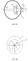
FIG. 3 is a schematic showing three pupil locations. - Referring to
FIG. 1 , an ocular wavefront-correction profiling system 100 includes awavefront mapping module 102 that provides a wavefront aberration map of a subject's eye as input to aprofile calculation module 104. Theprofile calculation module 104 also takespupil conditions 106 as input. Thepupil conditions 106 can include, for example, the size (e.g., radius) and position of the pupil relative to the limbus of the eye. Theprofile calculation module 104 includes amode solver 108 to determine a wavefront-correction profile 110 that can be used to perform laser ablation on the cornea to compensate for loss of focusing ability for multiple distances of regard (e.g., a near and a far distance of regard), as described in more detail below. Alternatively, the wavefront-correction profile 110 can be used to shape (e.g., using laser ablation) an optical element including contact lenses or spectacles (e.g., for testing the profile with feedback from the subject before surgery is performed) or an intraocular implant. For example, the wavefront-correction profile 110 can be used to shape a surface of a phakic or pseudophakic intraocular lens before insertion and placement. - Alternatively, in some embodiments, the
system 100 can take pupil and wavefront measurements after insertion and placement of an adjustable implant (e.g., a light-adjustable lens (LAL) whose shape changes in response to a applied optical radiation, or a nematic liquid-crystal lens whose index of refraction varies in response to an applied electric field). The measurements would subsequently be used to selectively modify optical properties of the adjustable implant (e.g., thickness of a LAL, or index of a nematic liquid crystal lens) according to the wavefront-correction profile 110. - The
wavefront mapping module 102 can use any of a variety of techniques for measuring or estimating a wavefront aberration map with respect to a reference surface (e.g., a plane). For example, thewavefront mapping module 102 can use measurement techniques and/or devices such as a spatially resolved refractometer, laser ray tracing, a Tcherning aberroscope, a Shack-Hartmann wavefront sensor, or dynamic skiascopy. The collected wavefront data represents aberrations over an area bounded by the subject's pharmacologically dilated pupil. Alternatively, thewavefront mapping module 102 can estimate wavefront aberrations based on anatomical measurements of a portion of the subject's eye. For example, a wavefront aberration map can be estimated from a map of corneal topography. Thus, the wavefront aberration map can represent aberrations due to propagation through some or all of the structures in the eye. - The
wavefront mapping module 102 provides a mathematical description of the wavefront aberration map to theprofile calculation module 104. One convenient mathematical description of the wavefront aberration map is a Zernike spatial mode expansion of the wavefront aberration map W(ρ, θ) (in polar coordinates) :


- Referring to
FIGS. 2A and 2B , the wavefront aberration map W(ρ,θ) represents a deviation of a wavefront 200 from areference plane 202 over apupil area 204. The wavefront 200 represents the effects of a spherical wavefront propagating from a point P on theretina 206, through the anatomical structures of the eye (e.g.,crystalline lens 208 and cornea 210), to thereference plane 202 just in front of thecornea 210. The flat (i.e., planar)reference plane 202 corresponds to an eye that is fixated on a "far" point (i.e., the farthest possible distance of regard). Alternatively, thereference plane 202 can have other shapes (e.g., spherical) for other assumed states of the eye. If the structures of the eye were "perfect" (i.e., if they caused no aberrations), the wavefront 200 would be flat, and would thus have W(ρ,θ) = 0 over thepupil area 204. - The
pupil area 204 and its location for different lighting and fixation (i.e., distance of regard) conditions. The center O of thepupil area 204 is measured relative to the center OL of thelimbus 212. The coordinates of a point ρ,θ in the aberration map W(ρ, θ) = 0 are defined in terms of a polar coordinate system centered at O. The radius R of thepupil area 204 is also measured. The largest size of thepupil area 204 corresponds to a pharmacologically dilated eye. Since thepupil area 204 is measured outside thecornea 210, the size of thepupil area 204 may be different from the actualinternal size 214 of the pupil. - The
pupil conditions 106 for a subject's eye are measured under various lighting and fixation conditions (e.g., using a pupillometer or camera). For example, room lighting is varied from less than 1 lux to 1000 lux while the subject fixates on points at specific distances. Thepupil conditions 106 include measurements of pupil size and position for fixation distances and room lighting that correspond to a subject's visual needs and/or desires for "far visual conditions" (e.g., driving at night, watching movies, working outdoors, etc.) and for "near visual conditions"(e.g., reading with bright light, looking at x-rays, playing piano, etc.) for bifocal correction. Pupil conditions for more than two fixation conditions can be included, e.g., for trifocal or multifocal correction. A pupil condition is measured or estimated based on a desired visual condition (e.g., a far or near visual condition). A desired visual condition can be measured directly or inferred on the basis of measurements indicative of a subject's intent to accommodate for the desired visual condition (e.g., measurement of contraction a subject's ciliary muscle). Such inferred measurements are fully described inU.S. Patent number 6,638,304 . - Referring to
FIG. 3 , in one embodiment, thepupil conditions 106 include three origin and radius measurements of a subject's pupil relative to the origin OL of thelimbus 210. A first origin O1 and radius R1 correspond to a pharmacologically dilatedpupil 301. A second origin O 2 and radius R 2 correspond to a scotopic (i.e., naturally dilated)pupil 302 while the eye is in a desired far fixation condition. A third origin O 3 and radius R 3 correspond to aconstricted pupil 303 while the eye is in a desired near fixation condition. - The
profile calculation module 104 uses relative pupil condition parameters in calculations performed by themode solver 108. The parameter S represents the relative ratio of pupil sizes: S 1 =1, S 2= R 2/R 1, S 3 =R 3/R 1 . The parameter di represents the distance of the shift between pupil conditions: d1 = 0, d2 = d(O1 ,O2 ), d 3 = d(O1 , O 3), where the function d(O 1, O 2) gives the distance between originsO 1 andO 2. Non-zero values of d2 , d 3, etc. represent shifting (or "decentration") of the pupil such that the pupil positions are non-concentric. The parameter a represents the angle from the horizontal of the shift between pupil conditions:

- In other embodiments, more or fewer pupil conditions are used.
- The
profile calculation module 104 determines an "add" parameter
O 3. Any of a variety of techniques can be used to estimate


- The
wavefront mapping module 102 provides "reference coefficients" for the spatial mode expansion of the wavefront aberration map W(ρ,θ) that is measured through the pupil (of radius R1 ) of the pharmacologically dilated eye. The coordinates of a point ρ, θ in the aberration map W(ρ, θ) are defined in terms of a polar coordinate system centered atO 1. The reference coefficients
mode solver 108 along with the relative pupil condition parameters S1, S2, d1, d2, a1, a2, and the add parameter
- The
mode solver 108 determines a set of "target coefficients" and one or more sets of "modified coefficients." The target coefficients
correction profiling system 100 generates a wavefront-correction profile 110 based on the difference between the "target wavefront profile" and a "reference wavefront profile" corresponding to the reference coefficients (the subject's pre-operative wavefront profile). - The target coefficients represent solutions satisfying one or more constraints on the modified coefficients. The modified coefficients correspond to a spatial mode expansion of a modified wavefront aberration map due to the effects of constriction of the pupil and decentration of the pupil. In one embodiment, the constraints on two sets of modified coefficients


pupil 301 to thescotopic pupil 302, and
scotopic pupil 302 to the constrictedpupil 303. - Other constraints are possible some of which can be expressed as a linear combination of the modified coefficients. For example, the
mode solver 108 can include constraints on the relative sizes of different coefficients (e.g., based on empirically derived preferences for some coefficients over others). - Target coefficients are selected based on a value of a metric compared to a threshold. For example, the metric may include the root mean square (RMS) of the target coefficients or the metric may include any quadratic function of the target coefficients. Each target coefficient can be weighted selectively. Initially, all the weights are equal and set to 1. The weights are then varied and different candidate solutions are computed.
- The modified coefficients


- For example, for an expansion up to N = 6 the modified defocus coefficients


- The
mode solver 108 selects the target coefficients that yield a metric satisfying a threshold condition. One threshold condition uses the point-spread functions of the modified wavefront aberration maps W (2)(ρ, θ) and W (3) (ρ,θ) that correspond to the modified coefficients


- Initially, the
mode solver 108 sets the target coefficients to the reference coefficients measured with the pharmacologically dilated pupil 301:
mode solver 108 searches in some neighborhood around these initial conditions for values of the target coefficients
mode solver 108 may generate multiple "candidate solutions" (i.e., candidate sets of target coefficients) that satisfy the constraints and yield the same or similar minimized values of the metric. In such cases, the ocular wavefront-correction profiling system 100 can select one or more of the candidate solutions according to the threshold condition. The threshold condition can be based on any of a variety of image plane metrics generated for each of the candidate solutions. - Examples of other metrics that can be used are the Optical Transfer Function (OTF) which is the Fourier Transform of the PSF, the Modulation Transfer Function (MTF) which is the magnitude of the OTF, and the Phase Transfer Function (PTF) which is the phase of the OTF. These metrics can be calculated for each of the pupil conditions and any wavelength. In some embodiments, the MTF for white light is calculated for the different candidate solutions. A final solution can be chosen as the candidate solution that satisfies the constraints and that maximizes the volume under three-dimensional plot of the MTF for one or both of the largest and the smallest pupil sizes.
- Alternatively, the ocular wavefront-
correction profiling system 100 can generate multiple wavefront-correction profiles (e.g., 5-10) based on the multiple candidate solutions. Multiple "preview lenses" can be made to allow a subject to test the visual effects of the various profiles (e.g., through visual acuity tests) and to select one to use. For example, the preview lenses can be used in trial frames, held by hand, or used as a contact lens. Alternatively, the multiple candidate solutions can be represented by a deformable mirror array to directly distort the wavefront before transmission to the subject's eye. A subject can view various objects at various pupil sizes and/or illumination conditions through an optical system with deformable mirrors to simulate the candidate solutions and choose the best compromise or best solution. These or other techniques can be used to simulate different candidate solutions. - The wavefront-
correction profile 110 can optionally account for predicted postoperative biological effects (e.g., wound healing) of a surgical procedure. For wavefront guided laser ablation of the cornea, theprofile 110 enables visual correction for multiple pupil and fixation conditions to be performed in only a single surgical procedure. Thus, instead of correcting vision by optimizing accommodation and minimizing higher order aberrations for a single set of pupil and fixation conditions, the ocular wavefront-correction profiling system 100 can produce aprofile 110 that incorporates selectively induced aberrations to trade-off correcting vision for multiple sets of pupil and fixation conditions. - It is to be understood that while the invention has been described in conjunction with the detailed description thereof, the foregoing description is intended to illustrate and not limit the scope of the invention, which is defined by the scope of the appended claims.
Claims (48)
- A method for providing multi-focal visual correction, using a profile calculation module (104), the method comprising:determining a plurality of pupil condition parameters (106) for an eye, wherein a pupil position corresponding to a first pupil condition is non-concentric with a pupil position corresponding to a second pupil condition; anddetermining a target wavefront profile (110) on the basis of the plurality of pupil condition parameters (106); and
determining a wavefront-correction profile (110) on the basis of the target wavefront profile;wherein determining the plurality of pupil condition parameters (106) for an eye comprises determining a distance of a shift between the pupil positions corresponding to the first and second pupil conditions, respectively, and an angle of the shift from the horizontal. - The method of claim 1, further comprising:determining a wavefront aberration map for the eye; anddetermining the wavefront-correction profile on the basis of the target wavefront profile and the wavefront aberration map.
- The method of claim 2, wherein the wavefront-correction profile is based on a difference between the target wavefront profile and a reference wavefront profile related to the wavefront aberration map.
- The method of claim 1, wherein determining a plurality of pupil conditions for an eye comprises determining a change in a size of a pupil of the eye.
- The method of claim 1, wherein determining a plurality of pupil conditions for an eye comprises determining a plurality of desired visual conditions; and estimating pupil conditions corresponding to each of the plurality of desired visual conditions.
- The method of claim 1, wherein determining a plurality of pupil conditions for an eye comprises simulating a plurality of desired visual conditions; and measuring pupil conditions resulting from each of the desired visual conditions.
- The method of claim 1, wherein determining a plurality of pupil conditions for an eye comprises determining a pupil condition corresponding to a lighting condition.
- The method of claim 7, wherein determining the pupil condition further comprises determining the pupil condition corresponding to a distance of regard.
- The method of claim 1, wherein determining a plurality of pupil conditions for an eye comprises determining a pupil condition corresponding to a wavelength of light.
- The method of claim 9, wherein determining the pupil condition further comprises determining the pupil condition corresponding to a distance of regard.
- The method of claim 1, wherein determining a plurality of pupil conditions for an eye comprises recording a pupil condition in an image.
- The method of claim 11, wherein recording the pupil condition in an image comprises recording the pupil condition in a video frame.
- The method of claim 11, wherein recording the pupil condition in an image comprises recording the pupil condition with an infrared camera.
- The method of claim 1, wherein determining a target wavefront profile comprises selecting a plurality of distances to objects of regard and determining the target wavefront profile at least in part on the basis of the plurality of distances.
- The method of claim 1, wherein determining a target wavefront profile comprises inferring desired visual conditions on the basis of measurements indicative of a subject's intent to accommodate for the desired visual conditions.
- The method of claim 1, wherein determining a plurality of pupil conditions for an eye comprises determining a pupil condition relative to an anatomical reference of the eye.
- The method of claim 16, wherein determining the pupil condition relative to the anatomical reference of the eye comprises determining a pupil size and a pupil position relative to the anatomical reference of the eye.
- The method of claim 16, wherein the anatomical reference is selected from the group consisting of the limbus, the iris, the dilated pupil, the constricted pupil, the pharmacologically dilated pupil, the conjunctiva, and the cornea.
- The method of claim 1, wherein the plurality of pupil conditions comprises at least three pupil conditions.
- The method of claim 1, wherein a first pupil condition is determined relative to a second pupil condition.
- The method of claim 2, further comprising:determining the wavefront-correction profile at least in part on the basis of a metric selected from the group consisting of a point spread function, an optical transfer function, a modular transfer function, and a phase transfer function.
- The method of claim 1, wherein determining the target wavefront profile comprises:providing a first set of modified coefficients as a function of a set of target coefficients and a first pupil condition;providing a second set of modified coefficients as a function of the set of target coefficients and a second pupil condition;selecting the set of target coefficients according to constraints for at least one of the first set of modified coefficients and at least one of the second set of modified coefficients; anddetermining the target wavefront profile based on the target coefficients.
- The method of claim 22, further comprising:determining a wavefront aberration map for the eye;providing a set of reference coefficients of spatial modes corresponding to the wavefront aberration map; anddetermining a wavefront-correction profile based on the target coefficients and the reference coefficients.
- The method of claim 22, wherein selecting the target coefficients comprises selecting the target coefficients based on a metric corresponding to the first and second set of modified coefficients, respectively.
- The method of claim 24, wherein the metric is selected from the group consisting of a point spread function, an optical transfer function, a modular transfer function, and a phase transfer function.
- The method of claim 24, wherein the metric is based on the volume under a three-dimensional plot of a transfer function.
- The method of claim 24, wherein selecting the target coefficients includes comparing a value of the metric to a threshold.
- The method of claim 2, further comprising:performing laser ablation on the cornea of the eye according to the wavefront-correction profile.
- The method of claim 28, wherein performing laser ablation comprises performing the laser ablation in a single surgical procedure.
- The method of claim 2, further comprising:shaping an optical element according to the wavefront-correction profile.
- The method of claim 30, wherein shaping comprises
performing laser ablation on the optical element according to the wavefront-correction profile. - The method of claim 30, wherein the optical element comprises a lens.
- The method of claim 32, wherein the lens comprises a contact lens.
- The method of claim 30, wherein the optical element comprises spectacles.
- The method of claim 30, wherein the optical element comprises an intraocular implant.
- The method of claim 30, wherein the optical element comprises deformable mirror.
- The method of claim 2, further comprising:irradiating a light-adjustable lens according to the wavefront-correction profile.
- The method of claim 2, wherein determining the wavefront-correction profile comprises:simulating an image based on a plurality of candidate wavefront-correction profiles for a subject; andselecting the wavefront-correction profile based on the feedback from the subject.
- An optical element for placement in an eye comprising:a surface that is shaped according to a wavefront-correction profile (110) that includes features based on a target wavefront profile;
wherein the target wavefront profile includes features based on:a plurality of pupil condition parameters (106) for the eye, wherein a pupil position corresponding to a first pupil condition is non-concentric with a pupil position corresponding to a second pupil condition, and the pupil condition parameters comprisea distance of a shift between the pupil positions corresponding to the first and second pupil conditions, respectively, andan angle of the shift from the horizontal. - The optical element of claim 39, wherein the wavefront-correction profile includes features based on the target wavefront profile and a wavefront aberration map for the eye.
- The optical element of claim 40, wherein the wavefront-correction profile includes features based on a difference between the target wavefront profile and a reference wavefront profile related to the wavefront aberration map.
- The optical element of claim 39, wherein the plurality of pupil conditions for the eye comprise a change in a size of a pupil of the eye.
- The optical element of claim 39, wherein the optical element comprises a contact lens.
- The optical element of claim 39, wherein the optical element comprises an intraocular implant.
- A system for providing multi-focal visual correction, the system comprising:a profile calculation module (104) configured to:determine a plurality of pupil condition parameters (106) for an eye, wherein a pupil position corresponding to a first pupil condition is non-concentric with a pupil position corresponding to a second pupil condition, wherein the pupil condition parameters comprisea distance of a shift between the pupil positions corresponding to the first and second pupil conditions, respectively, and an angle of the shift from the horizontal;determine a target wavefront profile (110) on the basis of the plurality of pupil condition parameters (106); anddetermine a wavefront-correction profile (110) on the basis of the target wavefront profile.
- The system of claim 45, further comprising:a wavefront mapping module configured to determine a wavefront aberration map for the eye;wherein the profile calculation module is configured to determine the wavefront-correction profile on the basis of the target wavefront profile and the wavefront aberration map.
- The system of claim 46, wherein the profile calculation module is configured to determine the wavefront-correction profile based on a difference between the target wavefront profile and a reference wavefront profile related to the wavefront aberration map.
- The system of claim 45, wherein the plurality of pupil conditions for the eye comprise a change in a size of a pupil of the eye.
Applications Claiming Priority (2)
| Application Number | Priority Date | Filing Date | Title |
|---|---|---|---|
| US10/894,255 US7341345B2 (en) | 2004-07-19 | 2004-07-19 | Ocular wavefront-correction profiling |
| PCT/US2005/025547 WO2006014624A2 (en) | 2004-07-19 | 2005-07-19 | Ocular wavefront-correction profiling |
Publications (3)
| Publication Number | Publication Date |
|---|---|
| EP1786312A2 EP1786312A2 (en) | 2007-05-23 |
| EP1786312A4 EP1786312A4 (en) | 2009-09-30 |
| EP1786312B1 true EP1786312B1 (en) | 2016-05-25 |
Family
ID=35731729
Family Applications (1)
| Application Number | Title | Priority Date | Filing Date |
|---|---|---|---|
| EP05773821.3A Not-in-force EP1786312B1 (en) | 2004-07-19 | 2005-07-19 | Ocular wavefront-correction profiling |
Country Status (4)
| Country | Link |
|---|---|
| US (5) | US7341345B2 (en) |
| EP (1) | EP1786312B1 (en) |
| JP (1) | JP4310363B2 (en) |
| WO (1) | WO2006014624A2 (en) |
Families Citing this family (57)
| Publication number | Priority date | Publication date | Assignee | Title |
|---|---|---|---|---|
| US6596260B1 (en) | 1993-08-27 | 2003-07-22 | Novartis Corporation | Aerosol container and a method for storage and administration of a predetermined amount of a pharmaceutically active aerosol |
| US7296893B2 (en) * | 2004-03-03 | 2007-11-20 | Visx, Incorporated | Transformation methods of wavefront maps from one vertex distance to another |
| US7547102B2 (en) | 2004-03-03 | 2009-06-16 | Amo Manufacturing Usa, Llc | Wavefront propagation from one plane to another |
| US7341345B2 (en) * | 2004-07-19 | 2008-03-11 | Massachusetts Eye & Ear Infirmary | Ocular wavefront-correction profiling |
| US8454160B2 (en) * | 2006-02-24 | 2013-06-04 | Amo Development, Llc | Zone extension systems and methods |
| US8474974B2 (en) * | 2006-02-24 | 2013-07-02 | Amo Development Llc. | Induced high order aberrations corresponding to geometrical transformations |
| US7717562B2 (en) * | 2006-02-24 | 2010-05-18 | Amo Development Llc. | Scaling Zernike coefficients to smaller pupil sizes for refractive treatments |
| US7695136B2 (en) * | 2007-08-01 | 2010-04-13 | Amo Development, Llc. | Wavefront refractions and high order aberration correction when wavefront maps involve geometrical transformations |
| DE102006036958B4 (en) * | 2006-08-08 | 2009-11-26 | Carl Zeiss Vision Gmbh | Method for determining the corrective properties of a visual aid |
| US8079707B2 (en) | 2006-10-25 | 2011-12-20 | Carl Zeiss Vision Gmbh | Eyeglass prescription method |
| US7481533B2 (en) * | 2006-10-30 | 2009-01-27 | Johnson & Johnson Vision Care, Inc | Method for designing multifocal contact lenses |
| CA2688170C (en) | 2007-05-24 | 2016-10-18 | Amo Development, Llc | Accommodation compensation systems and methods |
| DE102007032001B4 (en) * | 2007-07-09 | 2009-02-19 | Carl Zeiss Vision Gmbh | Device and method for determining the required correction of the refractive error of an eye |
| US7964833B2 (en) * | 2007-08-02 | 2011-06-21 | Elenza, Inc. | Multi-focal intraocular lens system and methods |
| ES2565244T3 (en) * | 2007-10-05 | 2016-04-01 | Essilor International (Compagnie Générale d'Optique) | A method to provide an ophthalmic lens for glasses by calculating or selecting a design |
| BRPI0818484A2 (en) * | 2007-10-31 | 2015-04-14 | Hoya Corp | Methods for evaluating spectacle lenses and for designing spectacle lenses, method and system for manufacturing spectacle lenses, and spectacle lens. |
| US8226230B2 (en) * | 2007-10-31 | 2012-07-24 | Hoya Corporation | Spectacle lens evaluating method, spectacle lens designing method using same, spectacle lens manufacturing method, spectacle lens manufacturing system, and spectacle lens |
| US9724190B2 (en) * | 2007-12-13 | 2017-08-08 | Amo Groningen B.V. | Customized multifocal ophthalmic lens |
| US7802883B2 (en) * | 2007-12-20 | 2010-09-28 | Johnson & Johnson Vision Care, Inc. | Cosmetic contact lenses having a sparkle effect |
| US20090219485A1 (en) * | 2008-02-29 | 2009-09-03 | Sarver Edwin J | Ocular wavefront system |
| US8331712B2 (en) * | 2008-06-25 | 2012-12-11 | Industrial Technology Research Institute | Method for designing computational optical imaging system |
| RU2011103798A (en) * | 2008-07-03 | 2012-08-10 | Окьюлар Оптикс, Инк. (Us) | SENSOR FOR ACCOMMODATION START SIGNAL |
| US8388130B2 (en) * | 2008-11-03 | 2013-03-05 | Vicoh, Llc | Non-deforming contact lens |
| US8083346B2 (en) | 2008-11-26 | 2011-12-27 | Liguori Management | Contact lens for keratoconus |
| US8960901B2 (en) * | 2009-02-02 | 2015-02-24 | Johnson & Johnson Vision Care, Inc. | Myopia control ophthalmic lenses |
| US7891810B2 (en) * | 2009-04-23 | 2011-02-22 | Liguori Management | Multifocal contact lens |
| JP5503193B2 (en) * | 2009-06-08 | 2014-05-28 | キヤノン株式会社 | Wavefront aberration measuring apparatus, exposure apparatus, and device manufacturing method |
| US8372319B2 (en) * | 2009-06-25 | 2013-02-12 | Liguori Management | Ophthalmic eyewear with lenses cast into a frame and methods of fabrication |
| WO2011030858A1 (en) | 2009-09-11 | 2011-03-17 | ダイキン工業株式会社 | Light-concentrating film, method for producing same, focusing element, solar cell, and focusing method |
| US8331048B1 (en) | 2009-12-18 | 2012-12-11 | Bausch & Lomb Incorporated | Methods of designing lenses having selected depths of field |
| US9256082B2 (en) | 2010-03-18 | 2016-02-09 | Vicoh, Llc | Laminated composite lens |
| US8408698B2 (en) * | 2010-03-18 | 2013-04-02 | Vicoh, Llc | Laminated composite lens |
| US20130060241A1 (en) * | 2010-04-27 | 2013-03-07 | Daniel S. Haddad | Dynamic real time active pupil centroid compensation |
| JP5915034B2 (en) * | 2011-09-02 | 2016-05-11 | 株式会社ニデック | Fundus imaging device with wavefront compensation |
| EP3130277B1 (en) * | 2011-12-13 | 2018-08-15 | Rodenstock GmbH | Universal objective refraction |
| TWI588560B (en) | 2012-04-05 | 2017-06-21 | 布萊恩荷登視覺協會 | Lenses, devices, methods and systems for refractive error |
| US9201250B2 (en) | 2012-10-17 | 2015-12-01 | Brien Holden Vision Institute | Lenses, devices, methods and systems for refractive error |
| WO2014059465A1 (en) | 2012-10-17 | 2014-04-24 | Brien Holden Vision Institute | Lenses, devices, methods and systems for refractive error |
| CA2906408C (en) * | 2013-03-15 | 2021-05-18 | Amo Development, Llc. | System and method for ophthalmic laser surgery employing eye tracking without eye docking |
| JP6470746B2 (en) | 2013-07-02 | 2019-02-13 | マサチューセッツ インスティテュート オブ テクノロジー | Apparatus and method for determining ophthalmic prescription |
| CA2916561A1 (en) | 2013-11-26 | 2015-06-04 | Abbott Medical Optics Inc. | System and method for measuring dysphotopsia |
| BR112017004765B1 (en) | 2014-09-09 | 2022-08-23 | Staar Surgical Company | LENS CONFIGURED FOR IMPLANTATION IN A HUMAN EYE |
| CN107077009B (en) | 2015-05-20 | 2019-11-15 | Rx视觉股份有限公司 | Method for modifying the adjustable lenticular refractive power of light |
| CN107920917B (en) * | 2015-08-13 | 2019-12-31 | 玄烔沅 | Adjustable intraocular lens |
| US10092177B1 (en) | 2015-12-30 | 2018-10-09 | Verily Life Sciences Llc | Device, system and method for image display with a programmable phase map |
| WO2017156077A1 (en) | 2016-03-09 | 2017-09-14 | Staar Surgical Company | Ophthalmic implants with extended depth of field and enhanced distance visual acuity |
| US10379356B2 (en) * | 2016-04-07 | 2019-08-13 | Facebook Technologies, Llc | Accommodation based optical correction |
| AU2017352030B2 (en) | 2016-10-25 | 2023-03-23 | Amo Groningen B.V. | Realistic eye models to design and evaluate intraocular lenses for a large field of view |
| US10739227B2 (en) | 2017-03-23 | 2020-08-11 | Johnson & Johnson Surgical Vision, Inc. | Methods and systems for measuring image quality |
| US11282605B2 (en) | 2017-11-30 | 2022-03-22 | Amo Groningen B.V. | Intraocular lenses that improve post-surgical spectacle independent and methods of manufacturing thereof |
| KR102560250B1 (en) | 2018-08-17 | 2023-07-27 | 스타 서지컬 컴퍼니 | Polymer composition showing the refractive index of the nanogradient |
| US11678975B2 (en) | 2019-04-05 | 2023-06-20 | Amo Groningen B.V. | Systems and methods for treating ocular disease with an intraocular lens and refractive index writing |
| US11583388B2 (en) | 2019-04-05 | 2023-02-21 | Amo Groningen B.V. | Systems and methods for spectacle independence using refractive index writing with an intraocular lens |
| US11564839B2 (en) | 2019-04-05 | 2023-01-31 | Amo Groningen B.V. | Systems and methods for vergence matching of an intraocular lens with refractive index writing |
| US11944574B2 (en) | 2019-04-05 | 2024-04-02 | Amo Groningen B.V. | Systems and methods for multiple layer intraocular lens and using refractive index writing |
| US11583389B2 (en) | 2019-04-05 | 2023-02-21 | Amo Groningen B.V. | Systems and methods for correcting photic phenomenon from an intraocular lens and using refractive index writing |
| US11529230B2 (en) | 2019-04-05 | 2022-12-20 | Amo Groningen B.V. | Systems and methods for correcting power of an intraocular lens using refractive index writing |
Citations (1)
| Publication number | Priority date | Publication date | Assignee | Title |
|---|---|---|---|---|
| WO2002087442A1 (en) * | 2001-04-27 | 2002-11-07 | Bausch & Lomb Incorporated | Iris pattern recognition and alignment |
Family Cites Families (16)
| Publication number | Priority date | Publication date | Assignee | Title |
|---|---|---|---|---|
| US4525043A (en) * | 1977-11-11 | 1985-06-25 | Leonard Bronstein | Contact lens |
| CA2172471C (en) * | 1995-03-29 | 1999-01-26 | Hua Qi | Apparatus for and method of simulating ocular optical system |
| US5755664A (en) * | 1996-07-11 | 1998-05-26 | Arch Development Corporation | Wavefront direction mapping catheter system |
| US6059775A (en) * | 1997-12-31 | 2000-05-09 | Nielsen; James M. | Multifocal corneal sculpturing |
| ATE336196T1 (en) * | 1998-03-04 | 2006-09-15 | Visx Inc | SYSTEM FOR LASER TREATMENT OF PRESALES VISION |
| US7281795B2 (en) * | 1999-01-12 | 2007-10-16 | Calhoun Vision, Inc. | Light adjustable multifocal lenses |
| JP3696041B2 (en) * | 2000-03-30 | 2005-09-14 | 株式会社ニデック | Ophthalmic equipment |
| JP4649035B2 (en) * | 2000-10-18 | 2011-03-09 | 株式会社トプコン | Eye characteristics measuring device |
| AU2002233323A1 (en) | 2001-02-09 | 2002-08-28 | Sensomotoric Instruments Gmbh | Multidimensional eye tracking and position measurement system |
| US6554429B1 (en) * | 2001-10-15 | 2003-04-29 | Alcon, Inc. | Method for determining accommodation |
| DE60236226D1 (en) * | 2001-10-19 | 2010-06-10 | Bausch & Lomb | Improvement of presbyopia |
| US20030199858A1 (en) * | 2002-04-18 | 2003-10-23 | Schelonka Lee Paul | Multifocal refractive surgery optimized to pupil dimensions and visual acuity requirements |
| EP1567907A4 (en) | 2002-12-06 | 2009-09-02 | Amo Mfg Usa Llc | Presbyopia correction using patient data |
| WO2004112576A2 (en) * | 2003-06-20 | 2004-12-29 | Visx, Incorporated | Systems and methods for prediction of objective visual acuity based on wavefront measurements |
| US7387387B2 (en) * | 2004-06-17 | 2008-06-17 | Amo Manufacturing Usa, Llc | Correction of presbyopia using adaptive optics and associated methods |
| US7341345B2 (en) * | 2004-07-19 | 2008-03-11 | Massachusetts Eye & Ear Infirmary | Ocular wavefront-correction profiling |
-
2004
- 2004-07-19 US US10/894,255 patent/US7341345B2/en active Active
-
2005
- 2005-07-19 WO PCT/US2005/025547 patent/WO2006014624A2/en active Application Filing
- 2005-07-19 EP EP05773821.3A patent/EP1786312B1/en not_active Not-in-force
- 2005-07-19 JP JP2007522646A patent/JP4310363B2/en not_active Expired - Fee Related
- 2005-11-22 US US11/287,510 patent/US7331668B2/en active Active
-
2008
- 2008-02-15 US US12/032,395 patent/US7901076B2/en not_active Expired - Fee Related
-
2011
- 2011-01-19 US US13/009,394 patent/US8267515B2/en active Active
-
2012
- 2012-08-29 US US13/598,232 patent/US20130050651A1/en not_active Abandoned
Patent Citations (1)
| Publication number | Priority date | Publication date | Assignee | Title |
|---|---|---|---|---|
| WO2002087442A1 (en) * | 2001-04-27 | 2002-11-07 | Bausch & Lomb Incorporated | Iris pattern recognition and alignment |
Also Published As
| Publication number | Publication date |
|---|---|
| EP1786312A2 (en) | 2007-05-23 |
| EP1786312A4 (en) | 2009-09-30 |
| US7901076B2 (en) | 2011-03-08 |
| US20060023162A1 (en) | 2006-02-02 |
| US20060176449A1 (en) | 2006-08-10 |
| JP4310363B2 (en) | 2009-08-05 |
| US20110112634A1 (en) | 2011-05-12 |
| US7331668B2 (en) | 2008-02-19 |
| US8267515B2 (en) | 2012-09-18 |
| WO2006014624B1 (en) | 2007-04-19 |
| JP2008506505A (en) | 2008-03-06 |
| WO2006014624A3 (en) | 2007-03-15 |
| US20130050651A1 (en) | 2013-02-28 |
| US20080198331A1 (en) | 2008-08-21 |
| US7341345B2 (en) | 2008-03-11 |
| WO2006014624A2 (en) | 2006-02-09 |
Similar Documents
| Publication | Publication Date | Title |
|---|---|---|
| EP1786312B1 (en) | Ocular wavefront-correction profiling | |
| JP5142712B2 (en) | Presbyopia correction and related methods using adaptive optics, wavefront sensor eye alignment and light shielding | |
| US7914149B2 (en) | Presbyopia correction program | |
| Oliveira et al. | Wavefront analysis and Zernike polynomial decomposition for evaluation of corneal optical quality | |
| US20060244916A1 (en) | Method for designing custom lenses for improved vision and correspondence lenses | |
| WO2008083015A9 (en) | Method and system for determining power profile for an eye | |
| US8591032B2 (en) | Opthalmic apparatuses, systems and methods | |
| US8882264B2 (en) | Simultaneous vision lenses, design strategies, apparatuses, methods, and systems | |
| CA3046726C (en) | Calculation of actual astigmatism correction and nomographs for corneal laser treatment | |
| CN110290768B (en) | Optimization of spherical aberration parameters for corneal laser treatment | |
| Yi | Wavefront aberrations and the depth of focus of the human eye | |
| WO2013159076A2 (en) | Vision enhancement systems and methods |
Legal Events
| Date | Code | Title | Description |
|---|---|---|---|
| PUAI | Public reference made under article 153(3) epc to a published international application that has entered the european phase |
Free format text: ORIGINAL CODE: 0009012 |
|
| 17P | Request for examination filed |
Effective date: 20070219 |
|
| AK | Designated contracting states |
Kind code of ref document: A2 Designated state(s): AT BE BG CH CY CZ DE DK EE ES FI FR GB GR HU IE IS IT LI LT LU LV MC NL PL PT RO SE SI SK TR |
|
| AX | Request for extension of the european patent |
Extension state: AL BA HR MK YU |
|
| R17D | Deferred search report published (corrected) |
Effective date: 20070419 |
|
| DAX | Request for extension of the european patent (deleted) | ||
| A4 | Supplementary search report drawn up and despatched |
Effective date: 20090827 |
|
| RIC1 | Information provided on ipc code assigned before grant |
Ipc: A61B 3/10 20060101ALI20090821BHEP Ipc: G02C 7/04 20060101ALI20090821BHEP Ipc: A61B 3/00 20060101AFI20070328BHEP |
|
| 17Q | First examination report despatched |
Effective date: 20091208 |
|
| GRAP | Despatch of communication of intention to grant a patent |
Free format text: ORIGINAL CODE: EPIDOSNIGR1 |
|
| INTG | Intention to grant announced |
Effective date: 20151221 |
|
| GRAS | Grant fee paid |
Free format text: ORIGINAL CODE: EPIDOSNIGR3 |
|
| GRAA | (expected) grant |
Free format text: ORIGINAL CODE: 0009210 |
|
| AK | Designated contracting states |
Kind code of ref document: B1 Designated state(s): AT BE BG CH CY CZ DE DK EE ES FI FR GB GR HU IE IS IT LI LT LU LV MC NL PL PT RO SE SI SK TR |
|
| REG | Reference to a national code |
Ref country code: GB Ref legal event code: FG4D |
|
| REG | Reference to a national code |
Ref country code: CH Ref legal event code: EP |
|
| REG | Reference to a national code |
Ref country code: IE Ref legal event code: FG4D Ref country code: AT Ref legal event code: REF Ref document number: 801542 Country of ref document: AT Kind code of ref document: T Effective date: 20160615 |
|
| REG | Reference to a national code |
Ref country code: DE Ref legal event code: R096 Ref document number: 602005049427 Country of ref document: DE |
|
| REG | Reference to a national code |
Ref country code: LT Ref legal event code: MG4D |
|
| REG | Reference to a national code |
Ref country code: NL Ref legal event code: MP Effective date: 20160525 |
|
| PG25 | Lapsed in a contracting state [announced via postgrant information from national office to epo] |
Ref country code: LT Free format text: LAPSE BECAUSE OF FAILURE TO SUBMIT A TRANSLATION OF THE DESCRIPTION OR TO PAY THE FEE WITHIN THE PRESCRIBED TIME-LIMIT Effective date: 20160525 Ref country code: NL Free format text: LAPSE BECAUSE OF FAILURE TO SUBMIT A TRANSLATION OF THE DESCRIPTION OR TO PAY THE FEE WITHIN THE PRESCRIBED TIME-LIMIT Effective date: 20160525 Ref country code: FI Free format text: LAPSE BECAUSE OF FAILURE TO SUBMIT A TRANSLATION OF THE DESCRIPTION OR TO PAY THE FEE WITHIN THE PRESCRIBED TIME-LIMIT Effective date: 20160525 |
|
| PGFP | Annual fee paid to national office [announced via postgrant information from national office to epo] |
Ref country code: DE Payment date: 20160726 Year of fee payment: 12 Ref country code: GB Payment date: 20160727 Year of fee payment: 12 |
|
| REG | Reference to a national code |
Ref country code: AT Ref legal event code: MK05 Ref document number: 801542 Country of ref document: AT Kind code of ref document: T Effective date: 20160525 |
|
| PG25 | Lapsed in a contracting state [announced via postgrant information from national office to epo] |
Ref country code: ES Free format text: LAPSE BECAUSE OF FAILURE TO SUBMIT A TRANSLATION OF THE DESCRIPTION OR TO PAY THE FEE WITHIN THE PRESCRIBED TIME-LIMIT Effective date: 20160525 Ref country code: SE Free format text: LAPSE BECAUSE OF FAILURE TO SUBMIT A TRANSLATION OF THE DESCRIPTION OR TO PAY THE FEE WITHIN THE PRESCRIBED TIME-LIMIT Effective date: 20160525 Ref country code: GR Free format text: LAPSE BECAUSE OF FAILURE TO SUBMIT A TRANSLATION OF THE DESCRIPTION OR TO PAY THE FEE WITHIN THE PRESCRIBED TIME-LIMIT Effective date: 20160826 Ref country code: LV Free format text: LAPSE BECAUSE OF FAILURE TO SUBMIT A TRANSLATION OF THE DESCRIPTION OR TO PAY THE FEE WITHIN THE PRESCRIBED TIME-LIMIT Effective date: 20160525 Ref country code: PT Free format text: LAPSE BECAUSE OF FAILURE TO SUBMIT A TRANSLATION OF THE DESCRIPTION OR TO PAY THE FEE WITHIN THE PRESCRIBED TIME-LIMIT Effective date: 20160926 |
|
| PG25 | Lapsed in a contracting state [announced via postgrant information from national office to epo] |
Ref country code: BE Free format text: LAPSE BECAUSE OF NON-PAYMENT OF DUE FEES Effective date: 20160731 Ref country code: IT Free format text: LAPSE BECAUSE OF FAILURE TO SUBMIT A TRANSLATION OF THE DESCRIPTION OR TO PAY THE FEE WITHIN THE PRESCRIBED TIME-LIMIT Effective date: 20160525 |
|
| PG25 | Lapsed in a contracting state [announced via postgrant information from national office to epo] |
Ref country code: CZ Free format text: LAPSE BECAUSE OF FAILURE TO SUBMIT A TRANSLATION OF THE DESCRIPTION OR TO PAY THE FEE WITHIN THE PRESCRIBED TIME-LIMIT Effective date: 20160525 Ref country code: EE Free format text: LAPSE BECAUSE OF FAILURE TO SUBMIT A TRANSLATION OF THE DESCRIPTION OR TO PAY THE FEE WITHIN THE PRESCRIBED TIME-LIMIT Effective date: 20160525 Ref country code: RO Free format text: LAPSE BECAUSE OF FAILURE TO SUBMIT A TRANSLATION OF THE DESCRIPTION OR TO PAY THE FEE WITHIN THE PRESCRIBED TIME-LIMIT Effective date: 20160525 Ref country code: SK Free format text: LAPSE BECAUSE OF FAILURE TO SUBMIT A TRANSLATION OF THE DESCRIPTION OR TO PAY THE FEE WITHIN THE PRESCRIBED TIME-LIMIT Effective date: 20160525 Ref country code: DK Free format text: LAPSE BECAUSE OF FAILURE TO SUBMIT A TRANSLATION OF THE DESCRIPTION OR TO PAY THE FEE WITHIN THE PRESCRIBED TIME-LIMIT Effective date: 20160525 |
|
| PG25 | Lapsed in a contracting state [announced via postgrant information from national office to epo] |
Ref country code: PL Free format text: LAPSE BECAUSE OF FAILURE TO SUBMIT A TRANSLATION OF THE DESCRIPTION OR TO PAY THE FEE WITHIN THE PRESCRIBED TIME-LIMIT Effective date: 20160525 Ref country code: AT Free format text: LAPSE BECAUSE OF FAILURE TO SUBMIT A TRANSLATION OF THE DESCRIPTION OR TO PAY THE FEE WITHIN THE PRESCRIBED TIME-LIMIT Effective date: 20160525 Ref country code: BE Free format text: LAPSE BECAUSE OF FAILURE TO SUBMIT A TRANSLATION OF THE DESCRIPTION OR TO PAY THE FEE WITHIN THE PRESCRIBED TIME-LIMIT Effective date: 20160525 |
|
| REG | Reference to a national code |
Ref country code: DE Ref legal event code: R097 Ref document number: 602005049427 Country of ref document: DE Ref country code: CH Ref legal event code: PL |
|
| PG25 | Lapsed in a contracting state [announced via postgrant information from national office to epo] |
Ref country code: MC Free format text: LAPSE BECAUSE OF FAILURE TO SUBMIT A TRANSLATION OF THE DESCRIPTION OR TO PAY THE FEE WITHIN THE PRESCRIBED TIME-LIMIT Effective date: 20160525 |
|
| PLBE | No opposition filed within time limit |
Free format text: ORIGINAL CODE: 0009261 |
|
| STAA | Information on the status of an ep patent application or granted ep patent |
Free format text: STATUS: NO OPPOSITION FILED WITHIN TIME LIMIT |
|
| PG25 | Lapsed in a contracting state [announced via postgrant information from national office to epo] |
Ref country code: FR Free format text: LAPSE BECAUSE OF NON-PAYMENT OF DUE FEES Effective date: 20160801 Ref country code: LI Free format text: LAPSE BECAUSE OF NON-PAYMENT OF DUE FEES Effective date: 20160731 Ref country code: CH Free format text: LAPSE BECAUSE OF NON-PAYMENT OF DUE FEES Effective date: 20160731 |
|
| REG | Reference to a national code |
Ref country code: FR Ref legal event code: ST Effective date: 20170331 |
|
| 26N | No opposition filed |
Effective date: 20170228 |
|
| REG | Reference to a national code |
Ref country code: IE Ref legal event code: MM4A |
|
| PG25 | Lapsed in a contracting state [announced via postgrant information from national office to epo] |
Ref country code: SI Free format text: LAPSE BECAUSE OF FAILURE TO SUBMIT A TRANSLATION OF THE DESCRIPTION OR TO PAY THE FEE WITHIN THE PRESCRIBED TIME-LIMIT Effective date: 20160525 |
|
| PG25 | Lapsed in a contracting state [announced via postgrant information from national office to epo] |
Ref country code: IE Free format text: LAPSE BECAUSE OF NON-PAYMENT OF DUE FEES Effective date: 20160719 |
|
| PG25 | Lapsed in a contracting state [announced via postgrant information from national office to epo] |
Ref country code: LU Free format text: LAPSE BECAUSE OF NON-PAYMENT OF DUE FEES Effective date: 20160719 |
|
| REG | Reference to a national code |
Ref country code: DE Ref legal event code: R119 Ref document number: 602005049427 Country of ref document: DE |
|
| GBPC | Gb: european patent ceased through non-payment of renewal fee |
Effective date: 20170719 |
|
| PG25 | Lapsed in a contracting state [announced via postgrant information from national office to epo] |
Ref country code: DE Free format text: LAPSE BECAUSE OF NON-PAYMENT OF DUE FEES Effective date: 20180201 Ref country code: GB Free format text: LAPSE BECAUSE OF NON-PAYMENT OF DUE FEES Effective date: 20170719 |
|
| PG25 | Lapsed in a contracting state [announced via postgrant information from national office to epo] |
Ref country code: HU Free format text: LAPSE BECAUSE OF FAILURE TO SUBMIT A TRANSLATION OF THE DESCRIPTION OR TO PAY THE FEE WITHIN THE PRESCRIBED TIME-LIMIT; INVALID AB INITIO Effective date: 20050719 Ref country code: CY Free format text: LAPSE BECAUSE OF FAILURE TO SUBMIT A TRANSLATION OF THE DESCRIPTION OR TO PAY THE FEE WITHIN THE PRESCRIBED TIME-LIMIT Effective date: 20160525 |
|
| PG25 | Lapsed in a contracting state [announced via postgrant information from national office to epo] |
Ref country code: TR Free format text: LAPSE BECAUSE OF FAILURE TO SUBMIT A TRANSLATION OF THE DESCRIPTION OR TO PAY THE FEE WITHIN THE PRESCRIBED TIME-LIMIT Effective date: 20160525 Ref country code: IS Free format text: LAPSE BECAUSE OF FAILURE TO SUBMIT A TRANSLATION OF THE DESCRIPTION OR TO PAY THE FEE WITHIN THE PRESCRIBED TIME-LIMIT Effective date: 20160525 |
|
| PG25 | Lapsed in a contracting state [announced via postgrant information from national office to epo] |
Ref country code: BG Free format text: LAPSE BECAUSE OF FAILURE TO SUBMIT A TRANSLATION OF THE DESCRIPTION OR TO PAY THE FEE WITHIN THE PRESCRIBED TIME-LIMIT Effective date: 20160525 |