EP1780462A1 - Process for modulated illumination of a road and headlamp using this process - Google Patents
Process for modulated illumination of a road and headlamp using this process Download PDFInfo
- Publication number
- EP1780462A1 EP1780462A1 EP06291634A EP06291634A EP1780462A1 EP 1780462 A1 EP1780462 A1 EP 1780462A1 EP 06291634 A EP06291634 A EP 06291634A EP 06291634 A EP06291634 A EP 06291634A EP 1780462 A1 EP1780462 A1 EP 1780462A1
- Authority
- EP
- European Patent Office
- Prior art keywords
- light
- lighting
- vehicle
- projector according
- road
- Prior art date
- Legal status (The legal status is an assumption and is not a legal conclusion. Google has not performed a legal analysis and makes no representation as to the accuracy of the status listed.)
- Granted
Links
- 238000000034 method Methods 0.000 title claims abstract description 43
- 238000005286 illumination Methods 0.000 title claims description 23
- 230000008569 process Effects 0.000 title claims description 6
- 238000001514 detection method Methods 0.000 claims abstract description 43
- 230000036961 partial effect Effects 0.000 claims abstract description 40
- 230000003287 optical effect Effects 0.000 claims description 24
- 238000012545 processing Methods 0.000 claims description 22
- 230000004907 flux Effects 0.000 claims description 15
- 230000005540 biological transmission Effects 0.000 claims description 9
- 230000000295 complement effect Effects 0.000 claims description 8
- 239000004973 liquid crystal related substance Substances 0.000 claims description 8
- 239000011521 glass Substances 0.000 claims description 4
- 229920000642 polymer Polymers 0.000 claims description 3
- 230000006870 function Effects 0.000 description 11
- 239000007788 liquid Substances 0.000 description 8
- 230000008033 biological extinction Effects 0.000 description 7
- 230000033001 locomotion Effects 0.000 description 7
- 230000015572 biosynthetic process Effects 0.000 description 5
- 206010052128 Glare Diseases 0.000 description 4
- 230000004313 glare Effects 0.000 description 4
- 230000002441 reversible effect Effects 0.000 description 4
- 230000011664 signaling Effects 0.000 description 4
- 241000282414 Homo sapiens Species 0.000 description 3
- 230000008901 benefit Effects 0.000 description 3
- 230000001276 controlling effect Effects 0.000 description 3
- 238000013461 design Methods 0.000 description 3
- 235000021183 entrée Nutrition 0.000 description 3
- 230000004438 eyesight Effects 0.000 description 3
- 210000000887 face Anatomy 0.000 description 3
- 210000003128 head Anatomy 0.000 description 3
- 239000011159 matrix material Substances 0.000 description 3
- 230000001105 regulatory effect Effects 0.000 description 3
- 241001465754 Metazoa Species 0.000 description 2
- 238000004458 analytical method Methods 0.000 description 2
- 239000002131 composite material Substances 0.000 description 2
- 239000013078 crystal Substances 0.000 description 2
- 230000000694 effects Effects 0.000 description 2
- 230000005684 electric field Effects 0.000 description 2
- 238000005259 measurement Methods 0.000 description 2
- 239000000203 mixture Substances 0.000 description 2
- 239000013307 optical fiber Substances 0.000 description 2
- 230000005855 radiation Effects 0.000 description 2
- 229920006395 saturated elastomer Polymers 0.000 description 2
- 230000003595 spectral effect Effects 0.000 description 2
- 238000001429 visible spectrum Methods 0.000 description 2
- 241000447437 Gerreidae Species 0.000 description 1
- OAICVXFJPJFONN-UHFFFAOYSA-N Phosphorus Chemical compound [P] OAICVXFJPJFONN-UHFFFAOYSA-N 0.000 description 1
- 241001639412 Verres Species 0.000 description 1
- 230000003044 adaptive effect Effects 0.000 description 1
- 239000000654 additive Substances 0.000 description 1
- 230000000996 additive effect Effects 0.000 description 1
- 230000002411 adverse Effects 0.000 description 1
- 238000003491 array Methods 0.000 description 1
- 238000006243 chemical reaction Methods 0.000 description 1
- 239000003086 colorant Substances 0.000 description 1
- 230000002950 deficient Effects 0.000 description 1
- 238000011161 development Methods 0.000 description 1
- 238000010891 electric arc Methods 0.000 description 1
- 229940082150 encore Drugs 0.000 description 1
- 238000000605 extraction Methods 0.000 description 1
- 238000002347 injection Methods 0.000 description 1
- 239000007924 injection Substances 0.000 description 1
- 230000000149 penetrating effect Effects 0.000 description 1
- 230000008447 perception Effects 0.000 description 1
- 230000002688 persistence Effects 0.000 description 1
- 229910052698 phosphorus Inorganic materials 0.000 description 1
- 239000011574 phosphorus Substances 0.000 description 1
- 230000001681 protective effect Effects 0.000 description 1
- 230000035484 reaction time Effects 0.000 description 1
- 230000009467 reduction Effects 0.000 description 1
- 230000002829 reductive effect Effects 0.000 description 1
- 230000004044 response Effects 0.000 description 1
- 230000002207 retinal effect Effects 0.000 description 1
- 239000000243 solution Substances 0.000 description 1
- 239000000758 substrate Substances 0.000 description 1
- 238000003786 synthesis reaction Methods 0.000 description 1
- 230000002123 temporal effect Effects 0.000 description 1
- XLYOFNOQVPJJNP-UHFFFAOYSA-N water Substances O XLYOFNOQVPJJNP-UHFFFAOYSA-N 0.000 description 1
Images


Classifications
-
- B—PERFORMING OPERATIONS; TRANSPORTING
- B60—VEHICLES IN GENERAL
- B60Q—ARRANGEMENT OF SIGNALLING OR LIGHTING DEVICES, THE MOUNTING OR SUPPORTING THEREOF OR CIRCUITS THEREFOR, FOR VEHICLES IN GENERAL
- B60Q1/00—Arrangement of optical signalling or lighting devices, the mounting or supporting thereof or circuits therefor
- B60Q1/02—Arrangement of optical signalling or lighting devices, the mounting or supporting thereof or circuits therefor the devices being primarily intended to illuminate the way ahead or to illuminate other areas of way or environments
- B60Q1/04—Arrangement of optical signalling or lighting devices, the mounting or supporting thereof or circuits therefor the devices being primarily intended to illuminate the way ahead or to illuminate other areas of way or environments the devices being headlights
- B60Q1/06—Arrangement of optical signalling or lighting devices, the mounting or supporting thereof or circuits therefor the devices being primarily intended to illuminate the way ahead or to illuminate other areas of way or environments the devices being headlights adjustable, e.g. remotely-controlled from inside vehicle
- B60Q1/08—Arrangement of optical signalling or lighting devices, the mounting or supporting thereof or circuits therefor the devices being primarily intended to illuminate the way ahead or to illuminate other areas of way or environments the devices being headlights adjustable, e.g. remotely-controlled from inside vehicle automatically
- B60Q1/085—Arrangement of optical signalling or lighting devices, the mounting or supporting thereof or circuits therefor the devices being primarily intended to illuminate the way ahead or to illuminate other areas of way or environments the devices being headlights adjustable, e.g. remotely-controlled from inside vehicle automatically due to special conditions, e.g. adverse weather, type of road, badly illuminated road signs or potential dangers
-
- B60K35/29—
-
- F—MECHANICAL ENGINEERING; LIGHTING; HEATING; WEAPONS; BLASTING
- F21—LIGHTING
- F21S—NON-PORTABLE LIGHTING DEVICES; SYSTEMS THEREOF; VEHICLE LIGHTING DEVICES SPECIALLY ADAPTED FOR VEHICLE EXTERIORS
- F21S41/00—Illuminating devices specially adapted for vehicle exteriors, e.g. headlamps
- F21S41/10—Illuminating devices specially adapted for vehicle exteriors, e.g. headlamps characterised by the light source
- F21S41/14—Illuminating devices specially adapted for vehicle exteriors, e.g. headlamps characterised by the light source characterised by the type of light source
- F21S41/141—Light emitting diodes [LED]
- F21S41/147—Light emitting diodes [LED] the main emission direction of the LED being angled to the optical axis of the illuminating device
-
- F—MECHANICAL ENGINEERING; LIGHTING; HEATING; WEAPONS; BLASTING
- F21—LIGHTING
- F21S—NON-PORTABLE LIGHTING DEVICES; SYSTEMS THEREOF; VEHICLE LIGHTING DEVICES SPECIALLY ADAPTED FOR VEHICLE EXTERIORS
- F21S41/00—Illuminating devices specially adapted for vehicle exteriors, e.g. headlamps
- F21S41/10—Illuminating devices specially adapted for vehicle exteriors, e.g. headlamps characterised by the light source
- F21S41/14—Illuminating devices specially adapted for vehicle exteriors, e.g. headlamps characterised by the light source characterised by the type of light source
- F21S41/141—Light emitting diodes [LED]
- F21S41/151—Light emitting diodes [LED] arranged in one or more lines
-
- F—MECHANICAL ENGINEERING; LIGHTING; HEATING; WEAPONS; BLASTING
- F21—LIGHTING
- F21S—NON-PORTABLE LIGHTING DEVICES; SYSTEMS THEREOF; VEHICLE LIGHTING DEVICES SPECIALLY ADAPTED FOR VEHICLE EXTERIORS
- F21S41/00—Illuminating devices specially adapted for vehicle exteriors, e.g. headlamps
- F21S41/20—Illuminating devices specially adapted for vehicle exteriors, e.g. headlamps characterised by refractors, transparent cover plates, light guides or filters
- F21S41/24—Light guides
-
- F—MECHANICAL ENGINEERING; LIGHTING; HEATING; WEAPONS; BLASTING
- F21—LIGHTING
- F21S—NON-PORTABLE LIGHTING DEVICES; SYSTEMS THEREOF; VEHICLE LIGHTING DEVICES SPECIALLY ADAPTED FOR VEHICLE EXTERIORS
- F21S41/00—Illuminating devices specially adapted for vehicle exteriors, e.g. headlamps
- F21S41/60—Illuminating devices specially adapted for vehicle exteriors, e.g. headlamps characterised by a variable light distribution
- F21S41/65—Illuminating devices specially adapted for vehicle exteriors, e.g. headlamps characterised by a variable light distribution by acting on light sources
- F21S41/663—Illuminating devices specially adapted for vehicle exteriors, e.g. headlamps characterised by a variable light distribution by acting on light sources by switching light sources
-
- G—PHYSICS
- G06—COMPUTING; CALCULATING OR COUNTING
- G06V—IMAGE OR VIDEO RECOGNITION OR UNDERSTANDING
- G06V20/00—Scenes; Scene-specific elements
- G06V20/50—Context or environment of the image
- G06V20/56—Context or environment of the image exterior to a vehicle by using sensors mounted on the vehicle
- G06V20/58—Recognition of moving objects or obstacles, e.g. vehicles or pedestrians; Recognition of traffic objects, e.g. traffic signs, traffic lights or roads
-
- B60K2360/191—
-
- B—PERFORMING OPERATIONS; TRANSPORTING
- B60—VEHICLES IN GENERAL
- B60Q—ARRANGEMENT OF SIGNALLING OR LIGHTING DEVICES, THE MOUNTING OR SUPPORTING THEREOF OR CIRCUITS THEREFOR, FOR VEHICLES IN GENERAL
- B60Q2300/00—Indexing codes for automatically adjustable headlamps or automatically dimmable headlamps
- B60Q2300/05—Special features for controlling or switching of the light beam
- B60Q2300/056—Special anti-blinding beams, e.g. a standard beam is chopped or moved in order not to blind
-
- B—PERFORMING OPERATIONS; TRANSPORTING
- B60—VEHICLES IN GENERAL
- B60Q—ARRANGEMENT OF SIGNALLING OR LIGHTING DEVICES, THE MOUNTING OR SUPPORTING THEREOF OR CIRCUITS THEREFOR, FOR VEHICLES IN GENERAL
- B60Q2300/00—Indexing codes for automatically adjustable headlamps or automatically dimmable headlamps
- B60Q2300/40—Indexing codes relating to other road users or special conditions
- B60Q2300/41—Indexing codes relating to other road users or special conditions preceding vehicle
-
- B—PERFORMING OPERATIONS; TRANSPORTING
- B60—VEHICLES IN GENERAL
- B60Q—ARRANGEMENT OF SIGNALLING OR LIGHTING DEVICES, THE MOUNTING OR SUPPORTING THEREOF OR CIRCUITS THEREFOR, FOR VEHICLES IN GENERAL
- B60Q2300/00—Indexing codes for automatically adjustable headlamps or automatically dimmable headlamps
- B60Q2300/40—Indexing codes relating to other road users or special conditions
- B60Q2300/42—Indexing codes relating to other road users or special conditions oncoming vehicle
-
- B—PERFORMING OPERATIONS; TRANSPORTING
- B60—VEHICLES IN GENERAL
- B60Q—ARRANGEMENT OF SIGNALLING OR LIGHTING DEVICES, THE MOUNTING OR SUPPORTING THEREOF OR CIRCUITS THEREFOR, FOR VEHICLES IN GENERAL
- B60Q2300/00—Indexing codes for automatically adjustable headlamps or automatically dimmable headlamps
- B60Q2300/40—Indexing codes relating to other road users or special conditions
- B60Q2300/45—Special conditions, e.g. pedestrians, road signs or potential dangers
-
- F—MECHANICAL ENGINEERING; LIGHTING; HEATING; WEAPONS; BLASTING
- F21—LIGHTING
- F21S—NON-PORTABLE LIGHTING DEVICES; SYSTEMS THEREOF; VEHICLE LIGHTING DEVICES SPECIALLY ADAPTED FOR VEHICLE EXTERIORS
- F21S41/00—Illuminating devices specially adapted for vehicle exteriors, e.g. headlamps
- F21S41/60—Illuminating devices specially adapted for vehicle exteriors, e.g. headlamps characterised by a variable light distribution
- F21S41/63—Illuminating devices specially adapted for vehicle exteriors, e.g. headlamps characterised by a variable light distribution by acting on refractors, filters or transparent cover plates
- F21S41/64—Illuminating devices specially adapted for vehicle exteriors, e.g. headlamps characterised by a variable light distribution by acting on refractors, filters or transparent cover plates by changing their light transmissivity, e.g. by liquid crystal or electrochromic devices
- F21S41/645—Illuminating devices specially adapted for vehicle exteriors, e.g. headlamps characterised by a variable light distribution by acting on refractors, filters or transparent cover plates by changing their light transmissivity, e.g. by liquid crystal or electrochromic devices by electro-optic means, e.g. liquid crystal or electrochromic devices
Definitions
- the present invention relates to a method of illuminating a road in front of a vehicle in which the projected light is modulated according to the detection of the presence in the environment at the front of the obstacle vehicle or particular objects or living beings identified.
- These particular objects may consist of other vehicles traveling in the same direction or in the opposite direction, the lighting being modulated to avoid dazzling drivers of these other vehicles. They can also consist of dazzling sources such as retro-reflective traffic signs, the lighting being modulated to avoid dazzle the driver of the vehicle by the reflection of the light beam sent by his own vehicle. They may also consist of obstacles identified as such, the lighting being modulated to illuminate them more particularly and bring them to the attention of the driver. They can still be made of characters present in front of the vehicle and likely to be dazzled by the light beams emitted by the projectors of the vehicle.
- the present invention also relates to a vehicle headlamp implementing this lighting method.
- the invention has applications in the field of vehicles traveling on roads such as, for example, motor vehicles or heavy goods vehicles. It finds, in particular, applications in the field of the projection of light by these vehicles.
- Road lighting is achieved by means of road projectors which each send a light beam directed towards the horizon.
- crossing lighting is achieved by means of crossing projectors, also called code projectors, each of which sends a downward beam of light, whose slope is typically 1%, giving visibility over a distance of about 60 to 80 meters.
- the beam is limited upward, in a plane perpendicular to the longitudinal axis of the vehicle, by a line called cut, and defined by a standard. This break is a maximum lighting line above which it is forbidden to illuminate in crossing mode. In countries with right-hand traffic, it is horizontal across the entire width of the road and on the lower left side of the road and forms an angle of 15 degrees above the horizontal on the lower right side of the road .
- This downward beam of light is intended to avoid dazzling drivers of vehicles traveling in the opposite direction and those of vehicles traveling in the same direction, in the road scene extending in front of the vehicle.
- the road lighting makes it possible to illuminate the road extending in front of the vehicle to substantially the horizon.
- the road lighting sends a light beam directed towards the horizon, that is to say right in front of the vehicle, which does not fail to dazzle the drivers of other vehicles traveling on the same road.
- this light beam is received by the traffic signs which, if they are highly retroreflective, can constitute a dazzling source for the driver of the vehicle emitting the driving beam.
- a projector for modulating the main illumination beam of the vehicle on the road.
- a projector is described in the patent applications DE - 199 07 943 or US - 5,938,319 .
- This projector makes it possible to project on the road a luminous indication, such as an arrow, to indicate, for example, the direction to be followed by the driver. This indication is then illuminated while the surrounding area is dark, that is to say unlit.
- a luminous indication is achieved by means of a projector comprising a plurality of micromirrors having dimensions of the order of 1/10 th or 1/100 th of a millimeter.
- This type of modulated light projector is intended to allow the projection of a crossing or road lighting with only one light source.
- it comprises, between a reflector and a single light source or between the reflector and an optical system for forming the light beam, an occultation screen interposed on the path of the light rays and comprising occultation zones consisting of crystals liquids capable of conferring on these zones several states of transparency.
- the blackout screen is completely transparent, allowing projection of the entire light beam on the road.
- the occultation screen is partly obscuring, thus allowing the projection of only a portion of the light beam emitted by the light source and, in particular, the part below the cutoff line.
- the document JP - 04 08 13 37 presents another embodiment according to which the liquid crystal screen is disposed directly on the same surface of the reflecting mirror surrounding the light source, so as to control the reflection factor, and thus modulate the beam of light rays reflected by this mirror associated with the LCD screen.
- a liquid crystal display causes a very significant yield reduction in terms of light flux, of the order of 50%, which implies the use of very powerful light sources to obtain after crossing the crystal screen a light beam in accordance with the various regulations concerning the luminous intensity at different characteristic points of a driving beam and a passing beam.
- a liquid crystal blanking screen such as that described in these patent applications, whatever its location, is very sensitive to the energy received and, in particular, to the temperature to which it is subjected.
- a liquid crystal occultation screen subjected to too much energy is necessarily defective.
- the light source used for road lighting is a powerful light source, too powerful for the LCD screen to physically resist. There is therefore a contradiction between the use of a liquid crystal display and the use of powerful light sources.
- Document is also known US - 6,281,806 a driver assistance device, in which one or more sensors are used to analyze the environment of the vehicle and are connected to a controlled light source.
- a processor receives the information from the sensor (s) and determines whether a particular object in that environment presents a potential hazard and should be particularly brought to the attention of the driver, which object may be a character, an animal or an inert obstacle. If so, the processor transmits a control signal for a light source to provide illumination of the particular object detected, and thus signals the driver.
- This light source is controlled so as to continuously illuminate the identified detected object, regardless of the respective movements of the vehicle and / or the detected object.
- the device comprises one or more detectors of the vehicle environment, an image signal processing system provided by this or these detectors, which identifies an obstacle in the environment of the vehicle and which delivers control signals to a servomotor controlling the elevation and azimuth orientation of a high intensity light source to that obstacle.
- this electromechanical device is of relatively complex design in order to be able to accommodate automobile-related stresses such as vibrations, and on the other hand that this device is not capable of taking into account only one obstacle at a time, and only one direction of illumination of this obstacle.
- the invention is placed in this context and its purpose is precisely to overcome the disadvantages of the techniques described above by proposing a lighting system able to illuminate only specific areas of the road while ensuring extinction in areas in which it is considered that this lighting would be inconvenient, because it would be dazzling for example for drivers of other vehicles traveling on the same road, or for the driver himself of the vehicle emitting the light beam, because of retroreflection for example by signs, or for characters present in front of the vehicle, or because it would be directed to areas in which it is considered preferable to attract less attention from the driver than in other areas which must be illuminated.
- the areas in which the illumination is to be modulated either by projecting less light in order not to dazzle the driver of another vehicle, the driver of the vehicle emitting the light beam or a character in the front environment of the vehicle, or by constantly projecting light to attract the attention of the driver of the vehicle, will be called "critical areas”.
- the detection of critical areas in which it is advisable not to send light rays must be carried out simply, quickly and reliably.
- Both detection and modulated lighting functions must be able to be performed by physically separate systems, in order to have information on the vehicle environment for other needs or applications, or with a single system physical. These two detection and modulated lighting functions must be fulfilled in real time, and thus require only simple and fast calculations.
- the invention also allows a contrario to propose a lighting system able to illuminate only certain critical areas of the road to bring them more particularly to the attention of the driver, while ensuring extinction or lighting of lesser intensity in areas considered to be less informative or non-critical.
- the detection of critical areas in which it is advisable on the contrary to send light rays to attract the attention of the driver of the vehicle can It can also be carried out in a simple manner, for example using algorithms from empty image processing which make it possible to distinguish in a series of consecutive images the trajectories of the moving obstacles from those of the fixed obstacles.
- the reaction times of the moving obstacle detection system is inversely proportional to the number of sensors used.
- the invention proposes a vehicle lighting method, in which the beam of light emitted is spatially modulated according to the information collected on the environment of the vehicle in front of the vehicle.
- this for example depending on the presence of any light sources on the road in front of the vehicle, that these sources are independent of the vehicle emitting the beam, like those of other vehicles traveling on the same road in the opposite direction or in the same meaning, or that these sources consist of reflections of the emitted beam, for example by retro-reflective traffic signs, or depending on the presence of obstacles to be illuminated preferentially or the presence of characters that are appropriate not to dazzle.
- This lighting method is intended to emit a lighting beam formed by the superposition of a plurality of partial beams each associated with a light source, each partial beam being emitted in a chosen direction, and extinguishing the light source of at least one partial beam such that the resulting beam contains no or few light rays in a predetermined direction.
- the method further includes detecting obstacles, characters or external light sources in the road scene, and controlling the individual power supply of the light sources to modulate the light beam emitted so that does not contain light rays emitted in the vicinity of these external light sources or characters, or in such a way that it contains light rays directed mainly towards the vicinity of the identified obstacles.
- the external light sources are constituted by the headlamps of a vehicle traveling in the opposite direction, or by the rear lights of a vehicle traveling in the same direction, the drivers of these vehicles should not be dazzled. .
- the external light sources consist of retroreflections caused by road signs on the lower side of the road or above it, it is advantageous not to illuminate these signs too strongly, so to continue to distinguish the indications they carry, without the retroreflected light becoming dazzling.
- the drivers of the other vehicles as well as the characters on the road and the road signs are thus in a relative shade, even total in the beam of light, the drivers of the other vehicles and the characters not being dazzled and the panels signaling are not dazzling.
- the invention also proposes a lighting projector implementing this modulated lighting method.
- this method is applied to the lighting zone of the road situated above the cutoff.
- the invention also relates to a projector implementing this method.
- This lighting projector modulated a road scene for a vehicle comprising at least one light source associated with a device for forming a lighting beam.
- the projector comprises a plurality of light sources, each emitting in association with the device for forming a light beam of illumination a partial light beam the superposition of the partial light beams forming a lighting beam, each source luminaire being individually adjustable to control the luminous flux of at least one partial light beam emitted in a predetermined direction in the illumination beam.
- the invention proposes a modulated lighting method of a road scene according to the information received by a detection unit and processed by a computer.
- This method can be used to modulate a beam of beam or a passing beam as a whole. It can also be used to illuminate a road scene in addition to conventional crossover lighting. This method then offers a greater range of illumination than for conventional crossing lighting, without risk of glare for other drivers of vehicles traveling on the same road or by road signs. the low sides of the road or above it. In the latter case, the method of the invention proposes to illuminate the road above the cutoff by not sending light rays in the direction of external light sources in this area.
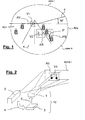
- FIG. 1 there is shown an example of a road scene.
- the route is referenced R. It has a low left side BC1 and a low side right BC2.
- a first V1 vehicle traveling in the opposite direction is on the other traffic line. It is located in zone 1, located above the cutoff, that is to say the area of the road scene illuminated by the projector of the invention.
- This vehicle V1 which is located in the infinite lighting zone is in an AV region of the light beam devoid of light rays, allowing its driver not to be dazzled.
- a second vehicle V2 traveling in the same direction is on the same traffic line. It is located in zone H, located below the cutoff, that is to say the area of the road scene illuminated by the projector of the invention.
- This vehicle V2 which is located in the near lighting zone is in an AR region of the light beam devoid of light rays, allowing its driver not to be dazzled.
- a P sign is on the lower right side of the road. It is located in the usual crossover lighting zone, zone H. It is not illuminated by the crossing lighting emitted by the projectors of the vehicle, because it is in a PS region of the light beam devoid of light rays, allowing the driver of the vehicle emitting the lighting beam according to the invention not to be dazzled by the retroreflections induced by this sign.
- all the light sources located in the road scene are detected, whether they are external sources coming from other vehicles, or passive sources consisting of retroreflective signs.
- Figure 2 shows, functionally, the projector of the invention with an example of illumination of the road scene.
- the road scene example of Figure 2 shows the vehicle V1 in an AV region around it, in the lighting zone I.
- the AV region devoid of light rays is created by means of an optical system 1 associated with a light source detection system 2 and possibly an electronic system 3 for processing the signals generated by the detection system 2.
- the optical system 1 and the electronic signal processing system 3 together form a system 10 for modulating the light emitted by a light source.
- Figure 2 there is shown the electronic system 3 and the optical system 1 independent of each other. In practice, the electronic system 3 can be integrated within the optical system 1 as will be seen later.
- the detection system 2 may consist of a thermal camera, which takes pictures of the road scene in front of the vehicle. These images of the road scene, called natural images, are transferred to the processing system 3, as shown by the arrow 4, which then performs an electronic processing of these images.
- This treatment makes it possible to locate the sources of heat in the road scene. These heat sources are constituted by other vehicles in motion, or by living beings, human beings or animals.
- image processing is described in the document FR 2,850,616 , in the name of the Applicant.
- the method described in this document is effective for detecting so-called "hot" sources, such as for example characters. Once a character is detected and located in the road scene in front of the vehicle, a simple image processing allows to locate the head of this character, by analysis of the silhouette and the characteristic shape of the shoulders.
- the camera 2 is a thermal camera capable of detecting a hot source such as a living being or a moving thermal engine vehicle, for example a thermal camera at 10 microns
- the camera detects the sources hot that appear brighter on the image than the rest of the image of the road scene.
- a thermal image is then obtained.
- an area to be treated that is to say the brightest area of the image, is selected. This selection is determined according to a predefined brightness threshold. Beyond this threshold, it is considered that the matrix element of the camera corresponds to a hot zone and therefore to the presence of a moving vehicle or a living being.
- Each micro-bolometric element of the matrix of the camera is thus thresholded to determine whether it is a hot zone or not the camera.
- the image processing performed by the electronic system 3 consists in selecting the zones of the thermal image beyond a certain temperature, that is to say a predefined threshold.
- a thresholded image that shows only the hot source in the road scene.
- This thresholded image has two levels, namely a white level and a black level.
- the hot source appears on a white saturated level while the rest of the image appears on a saturated black level.
- a similar method can be implemented with a sensitive camera working in the visible or the near infrared.
- the detection system 2 can also be an infrared camera associated with motion detection.
- the camera takes an image of a road scene and the electronic system 3 detects and locates the external light sources by detecting their relative movement.
- a thermal detection can be coupled with a motion detection to secure the detection of external light sources.
- the detection system 2 may also consist of a CCD or CMOS video camera, acquiring the images of the road scene in front of the vehicle. The processing of the images thus acquired can then be carried out as described in the patent application FR 04 12 266 of 18 November 2004 in the name of the Claimant.
- the method described in this document is very efficient for locating the light sources in the road scene in front of the vehicle, and for identifying the nature of these light sources solely according to the movement of their image on the sensitive surface of the light source detection system. 2. Knowing the nature of the light sources encountered, the signal processing system deduces the traffic condition in which the equipped vehicle is located, and in particular if it is necessary to control the switching of the vehicle headlights of a vehicle. first state "high beam” to a second state "low beam” or vice versa. The treatment as just described is performed in real time.
- the optical system 1 forms not a single illumination beam using a single light source, but a composite beam, resulting from the superposition of several elementary light beams, each generated by an elementary light source, each of these light sources being for example controllable individually according to the information received from the detection system 2 and processed by the processing system 3.
- the elementary or individual light sources in the present invention must be understood as covering two notions: on the one hand, light sources strictly speaking, such as for example a light-emitting diode, controllable independently of each other, and on the other hand for outputting optical fibers or light guides, the other input ends of which receive light from the same single common source, a modulation of each optical fiber or of each light guide being carried out so that the light intensity each output end can be controlled independently of the other output ends.
- the method for creating the AV zone that is devoid of light rays is as follows: the processing system 3 detects in the images taken by the camera 2 a light source in the road scene situated in front of the vehicle, for example in zone I at above the C cut, locate this source in space and determine its nature: projector, traffic light or road sign.
- the electronic system 3 determines which part of the light beam emitted by the vehicle is directed towards this direction, and controls the extinction of the corresponding elementary light source.
- FIG. 3 diagrammatically shows a first embodiment of a projector assembly that can be used to implement the method according to the present invention.
- This projector assembly generally designated by the reference 20, comprises a plurality of light sources 22 a, 22 b, ..., 22 n. These light sources consist, for example, of polychromatic light emitting diodes, emitting a white light.
- the diodes 22 a, 22 b, ..., 22 n are controlled by an electronic control circuit 25.
- light-emitting diode arrays currently available as power diodes, comprising a plurality of diodes juxtaposed on the same substrate.
- Each diode 22 a, 22 b, ..., 22 n is associated with a light guide 24 a, 24 b, ..., 24 n, respectively, for example via an optical device so the majority of the light flux emitted by the diode is injected into a first end of the corresponding light guide.
- the second ends 26 a, 26 b, ..., 26 n of the guides 24 a, 24 b, ..., 24 n are combined so as to be side by side and aligned with each other.
- the whole of the second ends 26 a, 26 b, ..., 26 n is then placed at the focus of a reflecting mirror 30, of the type with complex surface, such as for example described in documents FR 2,760,067 and FR 2,760,068 , in the name of the plaintiff.
- the mirrors described in these documents intended to equip motor vehicle headlamps, have the particularity of distributing the light vertically (formation of the horizontal cut and that which forms an angle of 15 degrees) as well as horizontally (distribution of the light on the ground) ensuring a very good homogeneity.
- the protective glass of the projector is freed from any optical function, and is therefore smooth, or very weakly deviating.
- the beam F i is generated in the direction i by the end 26 j of the guide 24 i , itself fed with light by the light source 22 i
- the beam F j is generated in the direction j by the end 26 j of the guide 24 j , itself powered by light from the light source 22 d .
- the partial beams F i , F j thus constitute a beam F, organized around an optical axis X-X '.
- the beam F then comprises all the elementary beams F a , F b , ..., F n , except the beam F i . It follows therefore that the light beam F illuminates the road scene in front of the vehicle, except in the direction i, corresponding to the elementary beam F i generated by the light source 22 i . Similarly, if the sources 22 i and 22 j are alone extinguished, the beam F then comprises all the elementary beams F a , F b , ..., F n , except the beams F i and F j .
- the light beam F illuminates the road scene in front of the vehicle, except in the directions i and j, corresponding to the elementary beams F i and F j generated by the light sources 22 j and 22 j .
- the beam F thus has in the directions i and j shaded areas, such as the areas AV, AR and PS in Figure 1.
- the directions i and j will be such that the shadow zones are merged with the zones AR and PS of FIG. 1, so as not to dazzle the driver of the vehicle V2 through its mirror, and not be dazzled by the retroreflection in the panel P.
- the headlamp 20 can for example illuminate the road above the horizontal cutoff to provide additional illumination to conventional crossing lighting that is to say in zone I of FIG. 1.
- the direction i will be such that the shadow zone is merged with the zone AV of FIG. 1, so as not to dazzle the driver of the vehicle V1.
- the directions i, j and k will be such that the shadow zones are merged with the zones AV, AR and PS of FIG. 1, so as not to dazzle the drivers of vehicles V1 and V2, and not to be dazzled by retroreflection in panel P.
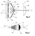
- FIG. 4 schematically shows a second embodiment of a projector assembly that can be used to implement the method according to the present invention.
- This projector assembly generally designated by reference numeral 40, there further comprises a plurality of light sources 22 a, 22 b, ..., 22 n, which may also consist of light emitting diodes polychroma tick, emitting white light.
- the diodes 22 a, 22 b, ..., 22 n are as in the previous example controlled by an electronic drive circuit 25.
- the diodes 22 a, 22 b, ..., 22 n are again associated with light guides 24 a, 24 b, ..., 24 n, respectively.
- a light injector device 42 a , 42 b may be interposed between the diodes and the light guides. , ..., 42 n .
- An example of such a light injector device 42 i is shown in more detail in FIG. 5.
- the device consists of a first collimator element 44 i , receiving all of the luminous flux emitted by the diode 22 i , and turning all this light into a beam of parallel rays.
- This parallel beam is then received by a convergent element 46 i , which focuses all the light to its focus F i .
- a light guide 24 i At this focus F i to be certain of recovering in the guide 24 i (not shown in FIG. 5) all of the light emitted by the diode 22 i .
- Such a light injector device can of course be used with the light guides of the embodiment of FIG. 3.
- all of the second ends 26 a, 26 b, ..., 26 n of the guides 24 a, 24 b, ..., 24 n are combined so as to be side next to each other, and aligned with each other.
- the whole of the second ends 26 a, 26 b, ..., 26 n is then placed at the focus of a convergent lens 48 plano-convex, the same type as those used to design elliptical lighting modules.
- a light source such as the filament of an incandescent lamp or the electric arc of a discharge lamp
- a mirror forms a real image of this source at its second focus, thus generating a spot of light concentration.
- a convergent lens is arranged so that its object focus coincides with the second focus of the elliptical mirror, so that this lens forms infinity an image of the spot of luminous concentration.
- This image at infinity then constitutes the light beam of illumination provided by the elliptical module, typically a driving beam.
- there is usually a cache in the object focal plane of the converging lens this cache intercepting the portion of the light rays that emerge from the converging lens being directed above the regulatory cutoff.
- the second ends 26 a, 26 b, ..., 26 n of the guides 24 a, 24 b, ..., 24 n constitute separate light sources, located at the same place as the concentration spot a modulus conventional elliptical lighting.
- the lens 48 forms images at infinity of these light sources 26 a , 26 b , ..., 26 n .
- the set of these infinite images then constitutes a lighting light beam F projected by the convergent plano-convex lens, and composed of the partial light beams F i , F j , the resulting beam F being again organized around an optical axis X-X '.
- the processing system 3 after having located a direction in which it is undesirable to emit light rays, to control the extinction of one or more sources 22 i , 22 j and / or 22 k to create in the total light beam the shaded areas AV, AR and / or PS of Figure 1, and thus avoid the glare of the drivers of other vehicles and / or avoid to be yourself dazzled by the signs.
- FIG. 6 schematically shows a third embodiment of a projector assembly that can be used to implement the method according to the present invention.
- This set projector generally designated by the reference 50, this time comprises a common light source 22.
- This common light source 22 consists of one or more separate sources, but whose light fluxes are all concentrated in one place.
- an elliptical module mirror as mentioned above, by disposing a discharge lamp at the first focus of a mirror substantially in the shape of an ellipsoid of revolution, and considering the concentration spot. formed at the second focus of the mirror as a common light source 22.
- the light coming from the common light source 22 is injected into a beam 52 of light guides, so that the first end of each individual guide 52 a, 52 b, ..., 52 n receives substantially the same amount of light.
- the light guides 52 a, 52 b, ..., 52 n in which light from the common source 22 was injected were then unbundled so that their second ends 56 a, 56 b, ..., 56 n serve as a light source for light guides 24 a, 24 b, ..., 24-n as in the embodiments of Figures 3 and 4, each guide 52 j being associated with a single guide 24 j.
- all of the second ends 26 a, 26 b, ..., 26 n of the guides 24 a, 24 b, ..., 24 n are combined so as to be side by side, and aligned with each other, at the focus of a lighting beam forming device 60.
- the device 60 may consist of a reflection system, similar to the mirror 30 in Figure 3, or a projection system, similar to the lens 48 of Figure 4, for emitting a light beam F organized around an optical axis X-X '.
- the modulation of the light penetrating into the guides 24 a , 24 b , ..., 24 n can be obtained by inserting a modulator shutter device 58 i between the output face of the guides 54 i and the input face of the guides 24. i .
- the modulators 58 i have been schematically represented by switches.
- a shutter device 58 i may consist of a simple mechanical or electromechanical shutter, allowing the interposition of an opaque element in the path of the light rays between the guides 52 i and 24 i or the controlled deviation of the light rays between these two guides.
- piezoelectric polymers may be used.
- mechanically defocusable lenses such as those known under the trade name "Varioptic”, or else micro-mirrors whose orientation is electrically controlled. Holographic lenses, as well as electrically defocusable flat lenses currently under development, can also be used for this purpose.
- the device 58 i may also consist of a shutter or an optical modulator, for example an electrochromic glass interposed in the path of the light rays between the guides 52 i and 24 j or an electro-controllable liquid crystal system.
- a lens of this type comprises an enclosure filled with a first conductive liquid, such as water, a drop of a second liquid being placed at rest on an area of a first face of an insulating wall of the enclosure, the two liquids being immiscible, of different optical indices and neighboring densities.
- the first liquid is conductive
- the second liquid is insulating, for example oil, and means are used to apply an electrical voltage between the conductive liquid and an electrode disposed on the second side of the wall.
- the drop of oil has a variable profile, because it will wet differently the wall on which it was deposited, as well as the difference in surface tension between them.
- two liquids is modified by the application of the electric field, which has the effect of modifying the focal length of the lens itself composed of this drop.
- the focal length is adjusted by applying the appropriate voltage, so that the lens focuses the light received from the guide 56 i on the input face of the guide 24 i , which transmits the light of a guide to the other, or that it focuses this light away from the input face of the guide 24 i , as shown in dashed lines in Figure 7, which transmits very little light d one guide to another.
- Embodiments of Figures 3, 4 and 6 have been shown to provide light modulation at different points of a column. Of course, it is possible to juxtapose several such columns, for an array of light sources 26, 26b, ..., 26 n, each of which can be controlled independently.
- This matrix disposed at the focus of a reflector 30 as in FIG. 3, or at the focus of a lens 48 as in FIG. 4, will make it possible to obtain a lighting beam of the road scene in front of the vehicle, presenting in FIG. directions i, j and / or k shaded areas, such as the areas AV, AR and PS in Figure 1.
- the processing system 3 after having located in the images captured by the detection system 2 an external light source such as V1, V2 or P in Figure 1, controls the extinction of the sources 22 i , 22 j and / or 22 k to create the shadow areas AV, AR and / or PS of Figure 1, and thus avoid the glare of drivers of other vehicles and / or avoid being oneself dazzled by the traffic signs.
- an external light source such as V1, V2 or P in Figure 1
- the numerical aperture of the partial beams F i , F j close to the optical axis XX ' is smaller than that of the partial beams F i , F j whose mean directions are farther from the optical axis X-X ', so as to increase the definition of the modulation of the light beam F in the vicinity of the optical axis XX' of the projector 20, 40 or 60.
- this optical axis X-X 'being parallel to the longitudinal axis of the vehicle is directed in a direction in which the information is most numerous for the driver of the vehicle: vehicles traveling in the same direction or in the opposite direction, characters and possible obstacles, and therefore need to be illuminated with modulated manner according to the invention with maximum selectivity.
- both the intensity and angular accuracy required are lower laterally than in the extension of the longitudinal axis of the vehicle.
- the light sources 26 i , 26 j are arranged in one or two superposed horizontal lines, so that the partial light beams F i , F j are joined.
- the total beam created by this line of light sources is close to that of a complementary low-altitude road beam, with the possibility of modulating different portions of this complementary beam, as has been seen above.
- the total beam created by this second line of light sources is generally less horizontally extended than the total beam created by the first line of light sources, and that the partial beams F k , F l created by the upper line are of greater horizontal extent. This minimizes the number of light sources in the second line, which significantly reduces the complexity of the system.
- the upper line of light sources makes it possible, in a beam complementary to a passing beam, to modulate in height the luminous intensity emitted to reduce the glare due to the signaling panels located at height on gantries, while allowing, on average distance, not to dazzle drivers of vehicles traveling in the opposite direction and above average height, such as trucks and some minivans, while illuminating the bottom of their vehicle, which remains visible.
- a complementary light beam to a passing beam modular as seen above, and which illuminates the areas of the road scene that are not illuminated by the regulatory passing beam, and which are likely to include an obstacle relevant for night driving or a potentially dazzling reflective object.
- the invention proposes constituting a regulatory lighting beam by the superposition of several elementary light beams, each of these beams being associated with an individual light source.
- FIG. 8 This is shown in Figure 8, where we see an example of a combination of a light source 22 i with a detector 122 i .
- the detectors 122i may advantageously consist of photodiodes or phototransistors.
- the light emitted by the source 22 i is injected into a guide 24 i by means of an injector 42 i , the second end 26 i of this guide being at the center of the an illumination beam forming system F i in the direction i such as a mirror 30 or a lens 48.
- the beam forming system 30 or 48 will form an image on the second end 26 i of the guide 24 i , applying the principle of reverse return of light.
- a separator 70 i on the guide 24 i , it will be possible to direct the light rays received from the external source S i in a guide 124 i so that these rays are finally received by a detector 122 i .
- the detector 122 i receives light, it means that an external light source S i is in the illumination beam F of the vehicle, and more particularly in the partial beam F i , and that it is therefore projectors or lights of another vehicle or a retro-reflective sign.
- the detector 122 i then sends a signal to an electronic element 80 j , which then controls the extinction of the source 22 i .
- the set of electronic elements 80 i can be combined in an electronic system 80 for processing the signals generated by all the detectors 122 i , the electronic system 80 can then be much simpler to produce, faster and more reliable than the processing system 3, as described in connection with Figure 2.
- the two detectors simultaneously provide a signal greater than a predetermined threshold, or if only the colorless filter detector provides a signal greater than a predetermined threshold, it means that the light received is white, and therefore comes from a vehicle traveling in the direction reverse. If only the detector with red filter provides a signal greater than a predetermined threshold, it means that the received light is red, and therefore comes from a vehicle traveling in the same direction.
- any light-emitting diode usually dedicated to the emission of a light beam, is also able to function as an optical detector in a spectral band close to its emission spectral range. .
- the white light emitting diodes whose flux is obtained, at least in part, by conversion using phosphors, are not very sensitive as light detectors in the visible spectrum (they have in practice only at high fluxes of ultraviolet rays). Nevertheless, today there exist miniature housings of comparable size to those of the above-mentioned diodes and having 2 to 4 emitter chips devoid of phosphorus, very close to each other. These diodes thus make it possible to create a white light beam by additive synthesis.
- Each light-emitting diode will then be driven by the electronic control circuit 25 so as to operate alternately in a transmission mode and in a reception mode.
- the time intervals during which the diodes operate in receive mode are chosen to be short enough so as not to disturb the lighting beam and be imperceptible to the driver's eyes.
- the rise and fall times of light-emitting diodes used in lighting and vehicle signaling are very low, and in any case much lower than the time constants of the human eye, such as retinal persistence, which are order of 25 Hertz, which allows switching operation with such short time intervals.
- the electronic control circuit 25 then controls for each light-emitting diode during a first time interval operation of the light-emitting diode for the formation of a partial light beam in the vehicle lighting beam, and during a second interval temporal operation of the diode in optical detection of external light source in the direction of the partial beam associated with the considered diode.
- the electronic control circuit 25 also comprises electronic detection circuits connected to each diode for receiving the measurement signal produced by the latter in response to the reception of a light beam emitted by an external source during the second time interval, in receiving mode, and outputting detection information resulting from a processing of the measurement signal.
- the electronic control circuit 25 also comprises for each diode switching circuits controlled during the second time interval, in reception mode, to inhibit the power supply of the light emitting diode during the first time interval, in transmission mode, in case of detecting the presence of an external light source during this second time interval of reception.
- the electronic control circuit 25 in such a way that a chip emitting in a length of determined wave, corresponding for example to the green color, emits a very brief pulse, of the order of a few milliseconds, and at low frequency, of the order of a few tens of Hertz, so as to be imperceptible by the eye human.
- the electronic control circuit 25 can then use in the time slot considered the chip emitting the complementary color of the first, for example the red color, as a detector. It is thus possible to produce an obstacle presence detector, even if it is not illuminated, in the angular sector and in the direction corresponding to those of the partial beam associated with this diode.
- a miniature housing comprising several radiation emitting chips of different wavelengths further has the advantage of being able to discriminate the nature of the received light, namely white or red, without the interposition of additional color filter.
- the diodes are sensitive to light rays of wavelength less than that of the light it emits.
- the simple analysis of the signals emitted by the diodes of the housing will make it possible to know the color of the light that they have received.
- the whole of a road lighting beam may consist of elementary light beams as described, so as to present to the driver an optimal illumination of the road scene. It may also be provided that the modulated lighting beam according to the invention is an additional beam to the passing beam, located above the cutoff of this beam dipped.
- the invention then provides a higher crossing illumination than usual lighting, located above the cut, while ensuring that this additional lighting does not dazzle the drivers of possible vehicles traveling on the same road, and does not dazzle the driver himself as a result of retroreflections on signs.
- This additional light obtained in zone I allows the driver to see the road scene beyond the cutoff C.
- the projector of the invention provides better perception and better visibility of the road to the driver. Indeed, this projector allows a classic lighting of the road scene and as well as more distant lighting, beyond the cut. Even if this lighting has dark or dark spots, even if they are numerous, for example in the case of heavy traffic, the driver necessarily has better visibility than with conventional lighting since this lighting more far away is additional lighting.
- the device can be used to draw the driver's attention to a potential obstacle, and illuminating this obstacle and not lighting up or less intensely its immediate vicinity.
- several optical devices for example several mirrors such as in FIG. 3 or several lenses such as 48 in FIG. 4, which will contribute together to form a single beam, each mirror and / or each lens being its turn associated with a group of light sources.
Abstract
Description
La présente invention concerne un procédé d'éclairage d'une route en avant d'un véhicule dans lequel la lumière projetée est modulée en fonction de la détection de la présence dans l'environnement à l'avant du véhicule d'obstacles ou d'objets particuliers ou d'êtres vivants identifiés. Ces objets particuliers peuvent être constitués d'autres véhicules circulant dans le même sens ou en sens inverse, l'éclairage étant modulé pour éviter d'éblouir les conducteurs de ces autres véhicules. Ils peuvent également être constitués de sources éblouissantes telles que des panneaux de signalisation rétroréfléchissants, l'éclairage étant modulé pour éviter l'éblouissement du conducteur du véhicule par la réflexion du faisceau lumineux envoyé par son propre véhicule. Ils peuvent aussi être constitués d'obstacles identifiés comme tels, l'éclairage étant modulé pour les éclairer plus particulièrement et les porter à l'attention du conducteur. Ils peuvent encore être constitués de personnages présents en avant du véhicule et susceptibles d'être éblouis par les faisceaux lumineux émis par les projecteurs du véhicule.The present invention relates to a method of illuminating a road in front of a vehicle in which the projected light is modulated according to the detection of the presence in the environment at the front of the obstacle vehicle or particular objects or living beings identified. These particular objects may consist of other vehicles traveling in the same direction or in the opposite direction, the lighting being modulated to avoid dazzling drivers of these other vehicles. They can also consist of dazzling sources such as retro-reflective traffic signs, the lighting being modulated to avoid dazzle the driver of the vehicle by the reflection of the light beam sent by his own vehicle. They may also consist of obstacles identified as such, the lighting being modulated to illuminate them more particularly and bring them to the attention of the driver. They can still be made of characters present in front of the vehicle and likely to be dazzled by the light beams emitted by the projectors of the vehicle.
La présente invention concerne également un projecteur de véhicule mettant en oeuvre ce procédé d'éclairage.The present invention also relates to a vehicle headlamp implementing this lighting method.
L'invention trouve des applications dans le domaine des véhicules circulant sur routes comme, par exemple, les véhicules automobiles ou les véhicules poids lourds. Elle trouve, en particulier, des applications dans le domaine de la projection de lumière par ces véhicules.The invention has applications in the field of vehicles traveling on roads such as, for example, motor vehicles or heavy goods vehicles. It finds, in particular, applications in the field of the projection of light by these vehicles.
Compte tenu du nombre croissant de véhicules circulant sur les routes, il est nécessaire de procurer, à ces véhicules et à leurs conducteurs, un éclairage le mieux adapté possible afin de réduire les risques d'accidents. En particulier la nuit, il est important que le conducteur puisse avoir une vision optimale de la route qui s'étend devant lui ainsi que des bas cotés de cette route. Autrement dit, pour des questions de sécurité, on cherche à améliorer l'éclairage de la route située devant le véhicule et, ainsi, à améliorer la vision de la scène de route par le conducteur du véhicule.Given the increasing number of vehicles on the roads, it is necessary to provide these vehicles and their drivers with the most appropriate lighting possible to reduce the risk of accidents. Especially at night, it is important that the driver can have an optimal view of the road that extends in front of him and low sides of this road. In other words, for safety reasons, it seeks to improve the lighting of the road in front of the vehicle and, thus, to improve the vision of the road scene by the driver of the vehicle.
Actuellement, tous les véhicules roulant sur la route comportent un dispositif d'éclairage de la route, utilisé en particulier la nuit ou lors d'intempéries. Classiquement, il existe sur les véhicules automobiles deux types d'éclairages :
- un éclairage dit "de route " qui éclaire la route intégralement sur une longue distance, d'environ 200 mètres, considérée comme l'infini pour le conducteur, et
- un éclairage dit "de croisement "qui éclaire la route sur une courte distance, de l'ordre de 60 mètres, pour éviter d'éblouir les conducteurs des véhicules circulant en sens inverse ou ceux des véhicules qui précèdent, ou encore les personnes pouvant se situer sur la route ou sur les bas cotés de la route.
- a "road" lighting which lights the road completely over a long distance, of about 200 meters, considered infinite for the driver, and
- a so-called "crossover" lighting which illuminates the road for a short distance, of the order of 60 meters, to avoid dazzling the drivers of vehicles traveling in the opposite direction or those of the preceding vehicles, or the persons who can located on the road or on the lower side of the road.
L'éclairage de route est réalisé au moyen de projecteurs de route qui envoient chacun un faisceau lumineux dirigé vers l'horizon.Road lighting is achieved by means of road projectors which each send a light beam directed towards the horizon.
L'éclairage de croisement est réalisé au moyen de projecteurs de croisement, appelés aussi projecteurs codes, qui envoient chacun un faisceau de lumière descendante, dont la pente est typiquement de 1%, donnant une visibilité sur une distance de l'ordre de 60 à 80 mètres. Le faisceau est limité vers le haut, dans un plan perpendiculaire à l'axe longitudinal du véhicule, par une ligne appelée coupure, et définie par une norme. Cette coupure est une ligne d'éclairage maximum au-dessus de laquelle il est interdit d'éclairer en mode de croisement. Dans les pays à circulation à droite, elle est horizontale sur toute la largeur de la route et sur le bas coté gauche de la route et elle forme un angle de 15 degrés au-dessus de l'horizontale sur le bas coté droit de la route.The crossing lighting is achieved by means of crossing projectors, also called code projectors, each of which sends a downward beam of light, whose slope is typically 1%, giving visibility over a distance of about 60 to 80 meters. The beam is limited upward, in a plane perpendicular to the longitudinal axis of the vehicle, by a line called cut, and defined by a standard. This break is a maximum lighting line above which it is forbidden to illuminate in crossing mode. In countries with right-hand traffic, it is horizontal across the entire width of the road and on the lower left side of the road and forms an angle of 15 degrees above the horizontal on the lower right side of the road .
Ce faisceau de lumière descendante a pour but d'éviter d'éblouir les conducteurs des véhicules circulant en sens inverse et ceux des véhicules circulant dans le même sens, dans la scène de route s'étendant devant le véhicule.This downward beam of light is intended to avoid dazzling drivers of vehicles traveling in the opposite direction and those of vehicles traveling in the same direction, in the road scene extending in front of the vehicle.
Cependant, un tel faisceau de lumière descendante n'offre qu'une visibilité réduite au conducteur du véhicule, à l'avant du véhicule. Cet éclairage est souvent insuffisant pour permettre au conducteur d'avoir une bonne visibilité de l'ensemble de la scène de route afin de pouvoir anticiper d'éventuels virages ou d'éventuels obstacles.However, such a downward beam of light provides only reduced visibility to the driver of the vehicle at the front of the vehicle. This lighting is often insufficient to allow the driver to have a good visibility of the entire road scene in order to anticipate possible turns or possible obstacles.
Au contraire, l'éclairage de route permet d'éclairer la route s'étendant devant le véhicule jusqu'à sensiblement l'horizon. Pour cela, l'éclairage de route envoie un faisceau lumineux dirigé vers l'horizon, c'est-à-dire droit devant le véhicule, ce qui ne manque pas d'éblouir les conducteurs des autres véhicules circulant sur la même route. De même, ce faisceau d'éclairage est reçu par les panneaux de signalisation qui, s'ils sont fortement rétroréfléchissants, peuvent constituer une source éblouissante pour le conducteur du véhicule émettant le faisceau de route.On the contrary, the road lighting makes it possible to illuminate the road extending in front of the vehicle to substantially the horizon. For this, the road lighting sends a light beam directed towards the horizon, that is to say right in front of the vehicle, which does not fail to dazzle the drivers of other vehicles traveling on the same road. Likewise, this light beam is received by the traffic signs which, if they are highly retroreflective, can constitute a dazzling source for the driver of the vehicle emitting the driving beam.
Actuellement, il n'existe que des dispositifs imparfaits permettant de moduler l'éclairage produit et d'éclairer la scène de route à l'infini ou sur une longue distance sans éclairer des zones prédéterminées de cette scène.Currently, there are only imperfect devices for modulating the lighting produced and illuminate the road scene to infinity or a long distance without illuminating predetermined areas of this scene.
On connaît par exemple un projecteur permettant de moduler le faisceau principal d'éclairage du véhicule sur la route. Un tel projecteur est décrit dans les demandes de brevets
Un autre type de projecteur d'automobile avec modulation de lumière est décrit dans les demandes de brevets
Le document
Cependant, en pratique, les projecteurs répondant à ce type de conception ne sont pas réalisables. En effet, un écran à cristaux liquides entraîne une baisse de rendement très importante en termes de flux lumineux, de l'ordre de 50 %, ce qui implique l'utilisation de sources lumineuses très puissantes pour obtenir après traversée de l'écran à cristaux liquides un faisceau lumineux conforme aux diverses réglementations concernant l'intensité lumineuse en différents points caractéristiques d'un faisceau de route et d'un faisceau de croisement. Par ailleurs, un écran d'occultation à cristaux liquides comme celui décrit dans ces demandes de brevets, quel que soit son emplacement, est très sensible à l'énergie reçue et, en particulier, à la température à laquelle il est soumis. Ainsi, un écran d'occultation à cristaux liquides soumis à une énergie trop forte est forcément défaillant. Or, la source lumineuse utilisée pour un éclairage de route est une source lumineuse puissante, trop puissante pour que l'écran d'occultation à cristaux liquides puisse résister physiquement. Il y a donc une contradiction entre l'emploi d'un écran à cristaux liquides et l'utilisation de sources lumineuses puissantes.However, in practice, projectors meeting this type of design are not feasible. Indeed, a liquid crystal display causes a very significant yield reduction in terms of light flux, of the order of 50%, which implies the use of very powerful light sources to obtain after crossing the crystal screen a light beam in accordance with the various regulations concerning the luminous intensity at different characteristic points of a driving beam and a passing beam. Moreover, a liquid crystal blanking screen such as that described in these patent applications, whatever its location, is very sensitive to the energy received and, in particular, to the temperature to which it is subjected. Thus, a liquid crystal occultation screen subjected to too much energy is necessarily defective. However, the light source used for road lighting is a powerful light source, too powerful for the LCD screen to physically resist. There is therefore a contradiction between the use of a liquid crystal display and the use of powerful light sources.
On connaît également du document
De manière plus précise, selon ce document, le dispositif comporte un ou plusieurs détecteurs de l'environnement du véhicule, un système de traitement du signal d'image fourni par ce ou ces détecteurs, qui identifie un obstacle dans l'environnement du véhicule et qui délivre des signaux de commande à un servomoteur contrôlant l'orientation en site et en azimut d'une source lumineuse de haute intensité vers cet obstacle. Il en résulte d'une part que ce dispositif électromécanique est de conception relativement complexe pour pouvoir s'accommoder des contraintes liées à l'automobile telles que les vibrations, et d'autre part que ce dispositif n'est capable que de prendre en compte qu'un seul obstacle à la fois, et une seule direction d'éclairage de cet obstacle.More specifically, according to this document, the device comprises one or more detectors of the vehicle environment, an image signal processing system provided by this or these detectors, which identifies an obstacle in the environment of the vehicle and which delivers control signals to a servomotor controlling the elevation and azimuth orientation of a high intensity light source to that obstacle. As a result, on the one hand, this electromechanical device is of relatively complex design in order to be able to accommodate automobile-related stresses such as vibrations, and on the other hand that this device is not capable of taking into account only one obstacle at a time, and only one direction of illumination of this obstacle.
L'invention se place dans ce contexte et elle a justement pour but de remédier aux inconvénients des techniques exposées précédemment en proposant un système d'éclairage capable de n'éclairer que certaines zones spécifiques de la route tout en assurant une extinction dans des zones dans lesquelles il est estimé que cet éclairage serait inopportun, parce qu'il serait par exemple éblouissant soit pour les conducteurs des autres véhicules circulant sur la même route, soit pour le conducteur lui-même du véhicule émettant le faisceau lumineux, du fait de la rétroréflexion provoquée par exemple par des panneaux de signalisation, soit encore pour des personnages présents devant le véhicule, ou encore parce qu'il serait dirigé vers des zones dans lesquelles il est estimé préférable de moins attirer l'attention du conducteur que dans d'autres zones qui doivent être éclairées.The invention is placed in this context and its purpose is precisely to overcome the disadvantages of the techniques described above by proposing a lighting system able to illuminate only specific areas of the road while ensuring extinction in areas in which it is considered that this lighting would be inconvenient, because it would be dazzling for example for drivers of other vehicles traveling on the same road, or for the driver himself of the vehicle emitting the light beam, because of retroreflection for example by signs, or for characters present in front of the vehicle, or because it would be directed to areas in which it is considered preferable to attract less attention from the driver than in other areas which must be illuminated.
Dans la présente invention, les zones dans lesquelles l'éclairage doit être modulé, soit en y projetant moins de lumière dans le but de ne pas éblouir le conducteur d'un autre véhicule, le conducteur du véhicule émetteur du faisceau lumineux ou un personnage dans l'environnement avant du véhicule, soit en y projetant en permanence de la lumière pour attirer l'attention du conducteur du véhicule, seront appelées des « zones critiques ».In the present invention, the areas in which the illumination is to be modulated, either by projecting less light in order not to dazzle the driver of another vehicle, the driver of the vehicle emitting the light beam or a character in the front environment of the vehicle, or by constantly projecting light to attract the attention of the driver of the vehicle, will be called "critical areas".
La détection des zones critiques dans lesquelles il convient de ne pas envoyer de rayons lumineux doit être effectuée de manière simple, rapide et fiable. Les deux fonctions de détection et d'éclairage modulé doivent pouvoir être remplies par des systèmes physiquement distincts, afin de pouvoir disposer des informations sur l'environnement du véhicule pour d'autres besoins ou applications, ou à l'aide d'un seul système physique. Ces deux fonctions de détection et d'éclairage modulé doivent être remplies en temps réel, et donc ne nécessiter que des calculs simples et rapides. L'invention permet également a contrario de proposer un système d'éclairage capable de n'éclairer que certaines zones critiques de la route pour les porter plus particulièrement à l'attention du conducteur, tout en assurant une extinction ou un éclairage d'intensité moindre dans des zones considérées comme étant moins porteuses d'informations, ou non critiques.The detection of critical areas in which it is advisable not to send light rays must be carried out simply, quickly and reliably. Both detection and modulated lighting functions must be able to be performed by physically separate systems, in order to have information on the vehicle environment for other needs or applications, or with a single system physical. These two detection and modulated lighting functions must be fulfilled in real time, and thus require only simple and fast calculations. The invention also allows a contrario to propose a lighting system able to illuminate only certain critical areas of the road to bring them more particularly to the attention of the driver, while ensuring extinction or lighting of lesser intensity in areas considered to be less informative or non-critical.
La détection des zones critiques dans lesquelles il convient au contraire d'envoyer des rayons lumineux pour attirer l'attention du conducteur du véhicule peut également être effectuée de manière simple, par exemple à l'aide des algorithmes issus des traitements d'images vides qui permettent de distinguer dans une série d'images consécutives les trajectoires des obstacles mobiles de celles des obstacles fixes. Les temps de réaction du système de détection d'obstacles mobiles est inversement proportionnel au nombre de capteurs utilisés.The detection of critical areas in which it is advisable on the contrary to send light rays to attract the attention of the driver of the vehicle can It can also be carried out in a simple manner, for example using algorithms from empty image processing which make it possible to distinguish in a series of consecutive images the trajectories of the moving obstacles from those of the fixed obstacles. The reaction times of the moving obstacle detection system is inversely proportional to the number of sensors used.
Pour atteindre le but qu'elle s'est fixée, l'invention propose un procédé d'éclairage pour véhicule, dans lequel le faisceau de lumière émise est modulé spatialement en fonction des informations recueillies sur l'environnement du véhicule à l'avant de celui-ci, par exemple en fonction de la présence d'éventuelles sources lumineuses sur la route devant le véhicule, que ces sources soient indépendantes du véhicule émetteur du faisceau, comme celles des autres véhicules circulant sur la même route dans le sens contraire ou dans le même sens, ou que ces sources soient constituées de réflexions du faisceau émis, par exemple par des panneaux de signalisation rétroréfléchissants, ou encore en fonction de la présence d'obstacles à éclairer de manière préférentielle ou de la présence de personnages qu'il convient de ne pas éblouir.To achieve the goal it has set for itself, the invention proposes a vehicle lighting method, in which the beam of light emitted is spatially modulated according to the information collected on the environment of the vehicle in front of the vehicle. this, for example depending on the presence of any light sources on the road in front of the vehicle, that these sources are independent of the vehicle emitting the beam, like those of other vehicles traveling on the same road in the opposite direction or in the same meaning, or that these sources consist of reflections of the emitted beam, for example by retro-reflective traffic signs, or depending on the presence of obstacles to be illuminated preferentially or the presence of characters that are appropriate not to dazzle.
Ce procédé d'éclairage a pour but d'émettre un faisceau d'éclairage formé de la superposition de plusieurs faisceaux partiels associés chacun à une source lumineuse, chaque faisceau partiel étant émis dans une direction choisie, et d'éteindre la source lumineuse d'au moins un faisceau partiel de manière à ce que le faisceau résultant ne contienne pas ou peu de rayons lumineux dans une direction prédéterminée. Le procédé comporte en outre la détection d'obstacles, de personnages ou de sources lumineuses extérieures se trouvant dans la scène de route, et la commande de l'alimentation individuelle des sources lumineuses pour moduler le faisceau lumineux émis de manière à ce qu'il ne contienne pas de rayons lumineux émis en direction du voisinage de ces sources lumineuses extérieures ou de ces personnages, ou de manière à ce qu'il contienne des rayons lumineux dirigés principalement en direction du voisinage des obstacles identifiés.This lighting method is intended to emit a lighting beam formed by the superposition of a plurality of partial beams each associated with a light source, each partial beam being emitted in a chosen direction, and extinguishing the light source of at least one partial beam such that the resulting beam contains no or few light rays in a predetermined direction. The method further includes detecting obstacles, characters or external light sources in the road scene, and controlling the individual power supply of the light sources to modulate the light beam emitted so that does not contain light rays emitted in the vicinity of these external light sources or characters, or in such a way that it contains light rays directed mainly towards the vicinity of the identified obstacles.
En effet, si par exemple les sources lumineuses extérieures sont constituées par les projecteurs d'un véhicule circulant en sens inverse, ou par les feux arrière d'un véhicule circulant dans le même sens, il convient de ne pas éblouir les conducteurs de ces véhicules. De même, si les sources lumineuses extérieures sont constituées par des rétroréflexions provoquées par des panneaux de signalisation sur le bas côté de la route ou au dessus de celle-ci, il est avantageux de ne pas éclairer ces panneaux de signalisation trop fortement, de manière à continuer à distinguer les indications qu'ils portent, sans que la lumière rétroréfléchie devienne éblouissante. De la même façon, dans le cas où des personnages ont été détectés dans l'environnement à l'avant du véhicule, il est préférable de ne pas en éclairer la partie supérieure, pour ne pas les éblouir et qu'ils conservent une vision nette de leur propre environnement.Indeed, if for example the external light sources are constituted by the headlamps of a vehicle traveling in the opposite direction, or by the rear lights of a vehicle traveling in the same direction, the drivers of these vehicles should not be dazzled. . Similarly, if the external light sources consist of retroreflections caused by road signs on the lower side of the road or above it, it is advantageous not to illuminate these signs too strongly, so to continue to distinguish the indications they carry, without the retroreflected light becoming dazzling. In the same way, in the case where characters have been detected in the environment at the front of the vehicle, it is preferable not to illuminate the upper part, not to dazzle them and they have a clear vision from their own environment.
Les conducteurs des autres véhicules ainsi que les personnages sur la route et les panneaux de signalisation sont ainsi dans une ombre relative, voire même totale dans le faisceau d'éclairage, les conducteurs des autres véhicules et les personnages n'étant pas éblouis et les panneaux de signalisation n'étant pas éblouissants.The drivers of the other vehicles as well as the characters on the road and the road signs are thus in a relative shade, even total in the beam of light, the drivers of the other vehicles and the characters not being dazzled and the panels signaling are not dazzling.
De manière similaire, dans le cas où des obstacles ont été identifiés en avant du véhicule, il est utile de les éclairer de manière continue, pour que le conducteur du véhicule ne les perde pas de vue et adapte sa conduite en conséquence.Similarly, in the case where obstacles have been identified in front of the vehicle, it is useful to illuminate them continuously so that the driver of the vehicle does not lose sight of them and adapts his driving accordingly.
L'invention propose également un projecteur d'éclairage mettant en oeuvre ce procédé d'éclairage modulé.The invention also proposes a lighting projector implementing this modulated lighting method.
De façon plus précise, l'invention concerne un procédé d'éclairage d'une scène de route par un projecteur de véhicule, caractérisé en ce qu'il comporte les opérations suivantes :
- émission d'une pluralité de faisceaux lumineux partiels associés chacun à une source lumineuse, chaque faisceau lumineux partiel étant émis dans une direction prédéterminée, la superposition des faisceaux partiels constituant un faisceau d'éclairage,
- modulation d'au moins une source lumineuse pour contrôler le flux lumineux d'au moins un faisceau lumineux partiel émis dans une direction prédéterminée dans le faisceau d'éclairage ;
- emitting a plurality of partial light beams each associated with a light source, each partial light beam being emitted in a predetermined direction, the superposition of the partial beams constituting a lighting beam,
- modulating at least one light source to control the luminous flux of at least one partial light beam emitted in a predetermined direction in the illumination beam;
Selon d'autres caractéristiques de ce procédé,
- il comporte en outre une étape de détection dans la scène de route de zones critiques ;
- les zones critiques sont constituées des têtes de personnages détectés dans la scène de route devant le véhicule automobile ;
- les zones critiques sont constituées de sources lumineuses extérieures au véhicule dans la scène de route devant le véhicule automobile.
- les sources lumineuses extérieures au véhicule sont détectées dans les directions prédéterminées dans le faisceau d'éclairage ;
- au moins une source lumineuse est modulée pour contrôler le flux lumineux d'au moins un faisceau lumineux partiel émis dans une direction dans laquelle une source lumineuse extérieure est détectée ;
- l'étape de détection est effectuée par un système de détection ;
- le procédé comporte en outre une étape de traitement du signal fourni par le système de détection pour piloter les sources lumineuses ;
- l'étape de détection est effectuée par les sources lumineuses utilisées en réception ;
- chaque source lumineuse est pilotée par le circuit électronique de pilotage de manière à fonctionner alternativement en un mode d'émission et en un mode de réception ;
- le procédé procure un faisceau d'éclairage additionnel à un faisceau de croisement ;
- le procédé modifie la coupure d'un faisceau de croisement.
- it further comprises a detection step in the road scene of critical areas;
- the critical zones consist of the heads of characters detected in the road scene in front of the motor vehicle;
- the critical areas consist of light sources outside the vehicle in the road scene in front of the motor vehicle.
- the light sources outside the vehicle are detected in the predetermined directions in the lighting beam;
- at least one light source is modulated to control the luminous flux of at least one partial light beam emitted in a direction in which an external light source is detected;
- the detection step is performed by a detection system;
- the method further comprises a signal processing step provided by the detection system for controlling the light sources;
- the detection step is performed by the light sources used in reception;
- each light source is driven by the electronic control circuit so as to operate alternately in a transmission mode and in a reception mode;
- the method provides an additional illumination beam to a passing beam;
- the method modifies the cut-off of a passing beam.
Avantageusement, ce procédé est appliqué sur la zone d'éclairage de la route située au-dessus de la coupure.Advantageously, this method is applied to the lighting zone of the road situated above the cutoff.
L'invention concerne également un projecteur mettant en oeuvre ce procédé.The invention also relates to a projector implementing this method.
Ce projecteur d'éclairage modulé d'une scène de route pour véhicule comportant au moins une source lumineuse associée à un dispositif de formation d'un faisceau lumineux d'éclairage.This lighting projector modulated a road scene for a vehicle comprising at least one light source associated with a device for forming a lighting beam.
Selon l'invention, le projecteur comporte une pluralité de sources lumineuses, chacune émettant en association avec le dispositif de formation d'un faisceau lumineux d'éclairage un faisceau lumineux partiel la superposition des faisceaux lumineux partiels formant un faisceau d'éclairage, chaque source lumineuse étant modulable individuellement pour contrôler le flux lumineux d'au moins un faisceau lumineux partiel émis dans une direction prédéterminée dans le faisceau d'éclairage.According to the invention, the projector comprises a plurality of light sources, each emitting in association with the device for forming a light beam of illumination a partial light beam the superposition of the partial light beams forming a lighting beam, each source luminaire being individually adjustable to control the luminous flux of at least one partial light beam emitted in a predetermined direction in the illumination beam.
Selon d'autres caractéristiques du projecteur,
- le dispositif de formation d'un faisceau lumineux d'éclairage est constitué d'un miroir réflecteur du type à surface complexe, au foyer duquel sont disposées les sources lumineuses ;
- le dispositif de formation d'un faisceau lumineux d'éclairage est constitué d'une lentille convergente au foyer de laquelle sont disposées les sources lumineuses ;
- les sources lumineuses sont constituées par des deuxièmes extrémités de guides de lumière transmettant la lumière reçue par leur première extrémité ;
- les premières extrémités des guides de lumière reçoivent chacune la lumière d'un dispositif modulateur de lumière dont le facteur de transmission peut être commandé individuellement ;
- le dispositif modulateur de lumière est constitué d'un obturateur mécanique ou électromécanique, de polymères piézo-électriques, de lentilles défocalisables mécaniquement, de micro-miroirs ;
- le dispositif modulateur de lumière est constitué d'un obturateur ou d'un modulateur optique, d'un verre électrochromique ou d'un système à cristaux liquides électro-commandables ;
- le dispositif modulateur de lumière est constitué d'une lentille à focale variable électriquement ;
- les dispositifs modulateurs de lumière sont intercalés entre la face d'entrée des guides de lumière et la face de sortie de guides de lumière primaires dont les faces d'entrée reçoivent toutes la lumière d'un dispositif émetteur de lumière unique ;
- les premières extrémités des guides de lumière reçoivent chacune la lumière d'un dispositif d'émission de lumière dont l'intensité peut être commandée individuellement ;
- les dispositifs d'émission de lumière sont constitués de diodes électroluminescentes émettant une lumière blanche ;
- des dispositifs injecteurs de lumière sont interposés entre les diodes électroluminescentes et les faces d'entrée des guides de lumière ;
- les diodes électroluminescentes sont pilotées par un circuit électronique de pilotage ;
- le projecteur comporte en outre un système de détection de sources lumineuses externes dans la scène de route devant le véhicule ;
- le système de détection est constitué d'une caméra thermique, d'une caméra infrarouge ou d'une caméra vidéo CCD ou CMOS ;
- le système de détection est constitué de photodiodes, de phototransistors ou de diodes électroluminescentes utilisées en réception ;
- les diodes électroluminescentes sont pilotées par le circuit électronique de pilotage de manière à fonctionner alternativement en un mode d'émission et en un mode de réception ;
- les sources lumineuses sont disposées selon une ligne horizontale ou selon deux lignes horizontales superposées, le faisceau d'éclairage étant un faisceau complémentaire à un faisceau de croisement.
- the device for forming a lighting light beam consists of a reflector mirror of the complex surface type, at the focus of which the light sources are arranged;
- the device for forming a lighting light beam consists of a convergent lens at the focus of which the light sources are arranged;
- the light sources are constituted by second ends of light guides transmitting the light received by their first end;
- the first ends of the light guides each receive light from a light modulator device whose transmission factor can be controlled individually;
- the light modulator device consists of a mechanical or electromechanical shutter, piezoelectric polymers, mechanically defocused lenses, micro-mirrors;
- the light modulator device comprises an optical shutter or modulator, an electrochromic glass or an electro-controllable liquid crystal system;
- the light modulator device consists of an electrically variable focal length lens;
- the light modulator devices are interposed between the input face of the light guides and the output face of primary light guides whose input faces all receive light from a single light emitting device;
- the first ends of the light guides each receive light from a light emitting device whose intensity can be controlled individually;
- the light-emitting devices consist of light-emitting diodes emitting a white light;
- light-injecting devices are interposed between the light-emitting diodes and the input faces of the light guides;
- the light-emitting diodes are controlled by an electronic control circuit;
- the projector further comprises a system for detecting external light sources in the road scene in front of the vehicle;
- the detection system consists of a thermal camera, an infrared camera or a CCD or CMOS video camera;
- the detection system consists of photodiodes, phototransistors or light-emitting diodes used in reception;
- the light-emitting diodes are driven by the electronic control circuit so as to operate alternately in a transmission mode and in a reception mode;
- the light sources are arranged in a horizontal line or in two superposed horizontal lines, the lighting beam being a beam complementary to a passing beam.
D'autres buts, caractéristiques et avantages de la présente invention ressortiront clairement de la description qui va maintenant être faite d'un exemple de réalisation donné à titre non limitatif en référence aux dessins annexés sur lesquels :
- La Figure 1 représente schématiquement une route éclairée par un éclairage de croisement classique combiné avec un éclairage selon l'invention ;
- La Figure 2 représente schématiquement les différents éléments formant un système d'éclairage modulé selon l'invention ;
- La Figure 3 représente schématiquement un premier mode de réalisation d'un projecteur produisant un éclairage selon l'invention ;
- La Figure 4 représente schématiquement un deuxième mode de réalisation d'un projecteur produisant un éclairage selon l'invention ;
- La Figure 5 représente schématiquement un aménagement d'une source lumineuse utilisable dans les projecteurs des Figures 3
et 4 - La Figure 6 représente schématiquement un troisième mode de réalisation d'un projecteur produisant un éclairage selon l'invention ;
- La Figure 7 représente schématiquement un exemple d'interrupteur optique utilisable dans le projecteur de la Figure 6, et
- La Figure 8 représente schématiquement un exemple d'un système combiné de d'éclairage et de détection utilisable pour mettre en oeuvre le procédé selon l'invention.
- Figure 1 shows schematically a road illuminated by conventional crossing lighting combined with lighting according to the invention;
- Figure 2 shows schematically the various elements forming a modulated lighting system according to the invention;
- Figure 3 schematically shows a first embodiment of a projector producing lighting according to the invention;
- Figure 4 schematically shows a second embodiment of a projector producing lighting according to the invention;
- Figure 5 schematically shows an arrangement of a light source for use in the projectors of Figures 3 and 4
- Figure 6 shows schematically a third embodiment of a projector producing lighting according to the invention;
- FIG. 7 schematically represents an example of an optical switch that can be used in the projector of FIG. 6, and
- FIG. 8 schematically represents an example of a combined lighting and detection system that can be used to implement the method according to the invention.
L'invention propose un procédé d'éclairage modulé d'une scène de route en fonction des informations reçues par un ensemble de détection et traitées par un calculateur. Ce procédé peut être utilisé pour moduler un faisceau de route ou un faisceau de croisement dans leur ensemble. Il peut également être utilisé pour éclairer une scène de route en complément d'un éclairage de croisement classique. Ce procédé offre alors une étendue d'éclairage plus importante que pour un éclairage de croisement habituel, sans risque d'éblouissement pour les autres conducteurs des véhicules circulant sur la même route ou par les panneaux de signalisation sur les bas cotés de la route ou au-dessus de celle-ci. Dans ce dernier cas, le procédé de l'invention propose d'éclairer la route au-dessus de la coupure en n'envoyant pas de rayons lumineux en direction de sources lumineuses extérieures se trouvant dans cette zone.The invention proposes a modulated lighting method of a road scene according to the information received by a detection unit and processed by a computer. This method can be used to modulate a beam of beam or a passing beam as a whole. It can also be used to illuminate a road scene in addition to conventional crossover lighting. This method then offers a greater range of illumination than for conventional crossing lighting, without risk of glare for other drivers of vehicles traveling on the same road or by road signs. the low sides of the road or above it. In the latter case, the method of the invention proposes to illuminate the road above the cutoff by not sending light rays in the direction of external light sources in this area.
Sur la Figure 1, on a représenté un exemple de scène de route. Sur cet exemple, la route est référencée R. Elle comporte un bas coté gauche BC1 et un bas coté droit BC2. Un premier véhicule V1 circulant en sens inverse est sur l'autre file de circulation. Il est situé dans la zone 1, située au dessus de la coupure, c'est-à-dire la zone de la scène de route éclairée par le projecteur de l'invention. Ce véhicule V1 qui est situé dans la zone d'éclairage à l'infini est dans une région AV du faisceau lumineux dépourvue de rayons lumineux, permettant à son conducteur de ne pas être ébloui.In Figure 1, there is shown an example of a road scene. In this example, the route is referenced R. It has a low left side BC1 and a low side right BC2. A first V1 vehicle traveling in the opposite direction is on the other traffic line. It is located in
Un deuxième véhicule V2 circulant dans le même sens est sur la même file de circulation. Il est situé dans la zone H, située en dessous de la coupure, c'est-à-dire la zone de la scène de route éclairée par le projecteur de l'invention. Ce véhicule V2 qui est situé dans la zone d'éclairage proche est dans une région AR du faisceau lumineux dépourvue de rayons lumineux, permettant à son conducteur de ne pas être ébloui.A second vehicle V2 traveling in the same direction is on the same traffic line. It is located in zone H, located below the cutoff, that is to say the area of the road scene illuminated by the projector of the invention. This vehicle V2 which is located in the near lighting zone is in an AR region of the light beam devoid of light rays, allowing its driver not to be dazzled.
Un panneau de signalisation P est sur le bas coté droit de la route. Il est situé dans la zone d'éclairage de croisement habituel, zone H. Il n'est pas éclairé par l'éclairage de croisement émis par les projecteurs du véhicule, car il est dans une région PS du faisceau lumineux dépourvue de rayons lumineux, permettant au conducteur du véhicule émettant le faisceau d'éclairage selon l'invention de ne pas être ébloui par les rétroréflexions induites par ce panneau de signalisation.A P sign is on the lower right side of the road. It is located in the usual crossover lighting zone, zone H. It is not illuminated by the crossing lighting emitted by the projectors of the vehicle, because it is in a PS region of the light beam devoid of light rays, allowing the driver of the vehicle emitting the lighting beam according to the invention not to be dazzled by the retroreflections induced by this sign.
D'une façon générale, dans l'invention, on détecte toutes les sources lumineuses situées dans la scène de route, qu'il s'agisse de sources extérieures provenant d'autres véhicules, ou de sources passives constituées de panneaux de signalisation rétroréfléchissants.In general, in the invention, all the light sources located in the road scene are detected, whether they are external sources coming from other vehicles, or passive sources consisting of retroreflective signs.
La Figure 2 représente, fonctionnellement, le projecteur de l'invention avec un exemple d'éclairage de la scène de route. L'exemple de scène de route de la Figure 2 montre le véhicule V1 dans une région AV autour de lui, dans la zone I d'éclairage.Figure 2 shows, functionally, the projector of the invention with an example of illumination of the road scene. The road scene example of Figure 2 shows the vehicle V1 in an AV region around it, in the lighting zone I.
La région AV dépourvue de rayons lumineux est créée au moyen d'un système optique 1 associé à un système de détection de sources lumineuses 2 et, éventuellement à un système électronique 3 de traitement des signaux générés par le système de détection 2. Le système optique 1 et le système électronique de traitement des signaux 3 forment ensemble un système 10 de modulation de la lumière émise par une source lumineuse. Sur la Figure 2, on a représenté le système électronique 3 et le système optique 1 indépendants l'un de l'autre. En pratique, le système électronique 3 peut être intégré au sein du système optique 1 comme on le verra par la suite.The AV region devoid of light rays is created by means of an
Le système de détection 2 peut être constitué d'une caméra thermique, qui réalise des prises d'images de la scène de route située devant le véhicule. Ces images de la scène de route, appelées images naturelles, sont transférées au système de traitement 3, comme schématisé par la flèche 4, qui effectue alors un traitement électronique de ces images. Ce traitement permet de localiser les sources de chaleur dans la scène de route. Ces sources de chaleur sont constituées par d'autres véhicules en mouvement, ou par des êtres vivants, êtres humains ou animaux. Un tel traitement des images est décrit dans le document
Plus précisément, dans le cas où la caméra 2 est une caméra thermique capable de détecter une source chaude telle qu'un être vivant ou un véhicule à moteur thermique en mouvement, par exemple une caméra thermique à 10 microns, alors la caméra détecte les sources chaudes qui apparaissent plus brillantes sur l'image que le reste de l'image de la scène de route. On obtient alors une image thermique. On sélectionne ensuite, pour cette image thermique, une zone à traiter, c'est-à-dire la zone la plus brillante de l'image. Cette sélection est déterminée en fonction d'un seuil de brillance prédéfini. Au-delà de ce seuil, on considère que l'élément matriciel de la caméra correspond à une zone chaude et donc à la présence d'un véhicule en mouvement ou à un être vivant. Chaque élément micro-bolométrique de la matrice de la caméra est ainsi seuillé pour déterminer s'il s'agit d'une zone chaude ou non de la caméra.More specifically, in the case where the
En d'autres termes, le traitement d'image réalisé par le système électronique 3 consiste à sélectionner les zones de l'image thermique au-delà d'une certaine température, c'est-à-dire d'un seuil prédéfini. On obtient alors une image seuillée qui fait apparaître uniquement la source chaude dans la scène de route. Cette image seuillée comporte deux niveaux, à savoir un niveau blanc et un niveau noir. De préférence, la source chaude apparaît sur un niveau saturé en blanc tandis que le reste de l'image apparaît sur un niveau saturé en noir. Un procédé analogue peut être mis en oeuvre avec une caméra sensible travaillant dans le visible ou le proche infrarouge.In other words, the image processing performed by the
Le système de détection 2 peut également être une caméra infrarouge associée à une détection par mouvement. Dans ce cas, la caméra assure la prise d'image d'une scène de route et le système électronique 3 détecte et localise les sources lumineuses extérieures par une détection de leur mouvement relatif. Selon une variante de l'invention, une détection thermique peut être couplée avec une détection de mouvement pour sécuriser la détection de sources lumineuses extérieures.The
Le système de détection 2 peut également être constitué d'une caméra vidéo CCD ou CMOS, réalisant l'acquisition des images de la scène de route devant le véhicule. Le traitement des images ainsi acquises peut alors être effectué comme cela a été décrit dans la demande de brevet
Le système de traitement 3 selon ce document antérieur effectue alors les opérations suivantes : acquisition d'une pluralité d'images représentant des scènes de route successives, puis extraction des sources lumineuses présentes dans ces images successives. Pour chacune des sources lumineuses ainsi extraites des images successives, le système de traitement 3 calcule alors :
- un relevé de la trajectoire de chaque source lumineuse à partir des positions successives occupées par la source lumineuse extraite dans les images successives ;
- une comparaison de la trajectoire relevée à une pluralité de trajectoires types afin de déterminer une catégorie de sources à laquelle appartient la source lumineuse extraite ;
- la détection d'une condition de circulation demandant la commutation des projecteurs d'un premier état d'éclairement vers un second état d'éclairement à partir d'au moins une catégorie de sources déterminée à laquelle appartient au moins la source lumineuse extraite.
- a survey of the trajectory of each light source from the successive positions occupied by the light source extracted in the successive images;
- comparing the surveyed trajectory with a plurality of standard trajectories to determine a category of sources to which the extracted light source belongs;
- detecting a traffic condition requesting the switching of the projectors from a first lighting state to a second state illumination from at least one determined source category to which at least the extracted light source belongs.
Ce document montre en effet que le simple mouvement d'une source lumineuse dans le champ de vision du conducteur, ou celui d'une caméra embarquée, est caractéristique notamment des évènements suivants :
- croisement d'un véhicule venant d'en face ;
- croisement d'un véhicule venant d'un virage à gauche ;
- croisement d'un véhicule venant d'un virage à droite ;
- croisement d'un panneau de signalisation ;
- croisement d'un lampadaire ;
- dépassement du véhicule dans lequel est mis en oeuvre le procédé par un autre véhicule ; et
- véhicule qui précède sur la route celui dans lequel est mis en oeuvre le procédé.
- crossing of a vehicle coming from opposite;
- crossing of a vehicle coming from a left turn;
- crossing of a vehicle coming from a right turn;
- crossing a traffic sign;
- crossing of a lamppost;
- exceeding the vehicle in which the method is implemented by another vehicle; and
- vehicle which precedes on the road the one in which the process is implemented.
Le procédé décrit dans ce document est très performant pour localiser les sources lumineuses dans la scène de route devant le véhicule, et pour identifier la nature de ces sources lumineuses uniquement selon le mouvement de leur image sur la surface sensible du système de détection de sources lumineuses 2. Connaissant ainsi la nature des sources lumineuses rencontrées, le système de traitement des signaux en déduit la condition de circulation dans laquelle se trouve le véhicule équipé, et en particulier s'il est nécessaire de commander la commutation des projecteurs du véhicule d'un premier état " feux de route " vers un second état " feux de croisement " ou inversement. Le traitement tel qu'il vient d'être décrit est réalisé en temps réel.The method described in this document is very efficient for locating the light sources in the road scene in front of the vehicle, and for identifying the nature of these light sources solely according to the movement of their image on the sensitive surface of the light source detection system. 2. Knowing the nature of the light sources encountered, the signal processing system deduces the traffic condition in which the equipped vehicle is located, and in particular if it is necessary to control the switching of the vehicle headlights of a vehicle. first state "high beam" to a second state "low beam" or vice versa. The treatment as just described is performed in real time.
Ces exemples de réalisations montrent qu'il est possible de savoir de manière fiable, dans une scène de route devant un véhicule, d'une part de quelle direction proviennent des rayons lumineux, et quelle en est la source émettrice : projecteurs d'un véhicule circulant en sens inverse, feux de signalisation d'un véhicule circulant dans le même sens ou panneau de signalisation rétroréfléchissant, et d'autre part dans quelle direction est situé un personnage, et plus particulièrement dans quelle direction, en site et en azimut, est située sa tête.These examples of achievements show that it is possible to know reliably, in a road scene in front of a vehicle, on the one hand which direction light rays come from, and what is the source emitting: projectors of a vehicle traveling in the opposite direction, signaling lights of a vehicle traveling in the same direction or retro-reflective traffic sign, and on the other hand in which direction a character is located, and more particularly in which direction, in elevation and in azimuth, is located his head.
Conformément à la présente invention, le système optique 1 forme non pas un faisceau d'éclairage unique à l'aide d'une source lumineuse unique, mais un faisceau composite, résultant de la superposition de plusieurs faisceaux lumineux élémentaires, générés chacun par une source lumineuse élémentaire, chacune de ces sources lumineuses étant par exemple contrôlable individuellement en fonction des informations reçues du système de détection 2 et traitées par le système de traitement 3.According to the present invention, the
Les sources lumineuses élémentaires ou individuelles dans la présente invention doivent être entendues comme recouvrant deux notions : d'une part des sources lumineuses à proprement parler, comme par exemple une diode électroluminescente, contrôlables indépendamment les unes des autres, et d'autre part des extrémités de sortie de fibres optiques ou de guides de lumière, dont les autres extrémités d'entrée reçoivent de la lumière d'une même source unique commune, une modulation de chaque fibre optique ou de chaque guide de lumière étant effectuée pour que l'intensité lumineuse de chaque extrémité de sortie puisse être commandée indépendamment des autres extrémités de sortie.The elementary or individual light sources in the present invention must be understood as covering two notions: on the one hand, light sources strictly speaking, such as for example a light-emitting diode, controllable independently of each other, and on the other hand for outputting optical fibers or light guides, the other input ends of which receive light from the same single common source, a modulation of each optical fiber or of each light guide being carried out so that the light intensity each output end can be controlled independently of the other output ends.
Ainsi, en fonction des informations recueillies sur l'environnement du véhicule, il sera possible de n'allumer que les sources lumineuses élémentaires correspondant à des faisceaux lumineux élémentaires dans la direction desquels aucune source lumineuse extérieure ou passive n'a été détectée par le système de détection 2 associé au système de traitement 3.Thus, depending on the information gathered on the vehicle environment, it will be possible to turn on only the elementary light sources corresponding to elementary light beams in the direction of which no external or passive light source has been detected by the system.
Le procédé de création de la zone AV exempte de rayons lumineux est le suivant : le système de traitement 3 détecte dans les images prises par la caméra 2 une source lumineuse dans la scène de route située devant le véhicule, par exemple dans la zone I au-dessus de la coupure C, localise cette source dans l'espace et détermine sa nature : projecteur, feu de signalisation ou panneau de signalisation.The method for creating the AV zone that is devoid of light rays is as follows: the
Après cette localisation de la source lumineuse extérieure et son identification, le système électronique 3 détermine quelle partie de faisceau lumineux émis par le véhicule est dirigée vers cette direction, et commande l'extinction de la source lumineuse élémentaire correspondante.After this location of the external light source and its identification, the
On a représenté schématiquement sur la Figure 3 un premier exemple de réalisation d'un ensemble projecteur utilisable pour mettre en oeuvre le procédé selon la présente invention. Cet ensemble projecteur, désigné globalement par la référence 20, comporte une pluralité de sources lumineuses 22a, 22b, ..., 22n. Ces sources lumineuses sont par exemple constituées de diodes électroluminescentes polychromatiques, émettant une lumière blanche. Les diodes 22a, 22b, ..., 22n sont pilotées par un circuit électronique de pilotage 25.FIG. 3 diagrammatically shows a first embodiment of a projector assembly that can be used to implement the method according to the present invention. This projector assembly, generally designated by the
On pourra par exemple utiliser des barrettes de diodes électroluminescentes disponibles actuellement en tant que diodes de puissance, comportant plusieurs diodes juxtaposées sur un même substrat.It is possible, for example, to use light-emitting diode arrays currently available as power diodes, comprising a plurality of diodes juxtaposed on the same substrate.
Chaque diode 22a, 22b, ..., 22n est associée à un guide de lumière 24a, 24b, ..., 24n, respectivement, par exemple par l'intermédiaire d'un dispositif optique, de manière à ce que la majeure partie du flux lumineux émis par la diode soit injectée dans une première extrémité du guide de lumière correspondant. Les deuxièmes extrémités 26a, 26b, ..., 26n des guides 24a, 24b, ..., 24n sont réunies de manière à être côte à côte, et alignées les unes avec les autres.Each
L'ensemble des deuxièmes extrémités 26a, 26b, ..., 26n est alors placé au foyer d'un miroir réflecteur 30, du type à surface complexe, tel que par exemple décrit dans les documents
L'ensemble des deuxièmes extrémités 26a, 26b, ..., 26n au foyer du miroir 30 est ainsi placé au même endroit par rapport au miroir 30 que celui où est placé le filament d'une lampe à incandescence classique.The whole of the second ends 26 a, 26 b, ..., 26 n to the focus of the
Lorsque toutes les sources lumineuses 22a, 22b, ..., 22n sont allumées, l'ensemble des extrémités 26a, 26b, ..., 26n des guides de lumière 24a, 24b, ..., 24n se comporte alors comme un filament continu. Le miroir 30 forme alors un faisceau F d'éclairage conventionnel. Ce faisceau F est en fait composite, et il résulte de la superposition des faisceaux lumineux élémentaires, générés chacun par une des sources lumineuses 22a, 22b, ..., 22n. Ainsi, comme on le voit schématiquement sur la Figure 3, le faisceau Fi est généré dans la direction i par l'extrémité 26j du guide 24i, elle-même alimentée en lumière par la source lumineuse 22i, et le faisceau Fj est généré dans la direction j par l'extrémité 26j du guide 24j, elle-même alimentée en lumière par la source lumineuse 22j. Les faisceaux partiels Fi, Fj constituent ainsi un faisceau F, organisé autour d'un axe optique X-X'.Where all the
Dans ces conditions, si la source 22i est seule éteinte, toutes les autres étant allumées, le faisceau F comprend alors tous les faisceaux élémentaires Fa, Fb, ..., Fn, sauf le faisceau Fi. Il en résulte donc que le faisceau lumineux F éclaire la scène de route devant le véhicule, sauf dans la direction i, correspondant au faisceau élémentaire Fi engendré par la source lumineuse 22i. De même, si les sources 22i et 22j sont seules éteintes, le faisceau F comprend alors tous les faisceaux élémentaires Fa, Fb, ..., Fn, sauf les faisceaux Fi et Fj. Il en résulte donc que le faisceau lumineux F éclaire la scène de route devant le véhicule, sauf dans les directions i et j, correspondant aux faisceaux élémentaires Fi et Fj engendré par les sources lumineuses 22j et 22j. Le faisceau F présente donc dans les directions i et j des zones d'ombre, telles que les zones AV, AR et PS sur la Figure 1.Under these conditions, if the
Si le projecteur 20 est utilisé pour procurer un faisceau de croisement, les directions i et j seront telles que les zones d'ombre soient confondues avec les zones AR et PS de la Figure 1, de manière à ne pas éblouir le conducteur du véhicule V2 par l'intermédiaire de son rétroviseur, et à ne pas être ébloui par la rétroréflexion dans le panneau P.If the
Si le projecteur 20 est utilisé pour éclairer une scène de route en complément d'un éclairage de croisement classique, il peut par exemple éclairer la route au-dessus de la coupure horizontale pour offrir un éclairage additionnel à un éclairage de croisement conventionnel, c'est-à-dire dans la zone I de la Figure 1. La direction i sera telle que la zone d'ombre soit confondue avec la zone AV de la Figure 1, de manière à ne pas éblouir le conducteur du véhicule V1.If the
Si le projecteur 20 est utilisé pour procurer un faisceau de route, les directions i, j et k seront telles que les zones d'ombre soient confondues avec les zones AV, AR et PS de la Figure 1, de manière à ne pas éblouir les conducteurs des véhicules V1 et V2, et à ne pas être ébloui par la rétroréflexion dans le panneau P.If the
Il suffira alors que le système de traitement 3, après avoir localisé une source lumineuse extérieure telle que V1, V2 ou P sur la Figure 1, commande l'extinction des sources 22i, 22j et/ou 22k pour créer les zones d'ombre AV, AR et/ou PS de la Figure 1, et ainsi éviter l'éblouissement des conducteurs des autres véhicules et/ou éviter d'être soi-même ébloui par les panneaux de signalisation.It will then be sufficient for the
On a représenté schématiquement sur la Figure 4 un deuxième mode de réalisation d'un ensemble projecteur utilisable pour mettre en oeuvre le procédé selon la présente invention. Cet ensemble projecteur, désigné globalement par la référence 40, comporte là encore une pluralité de sources lumineuses 22a, 22b, ..., 22n, qui peuvent également être constituées de diodes électroluminescentes polychroma-tiques, émettant une lumière blanche. Les diodes 22a, 22b, ..., 22n sont comme dans l'exemple précédent pilotées par un circuit électronique de pilotage 25.FIG. 4 schematically shows a second embodiment of a projector assembly that can be used to implement the method according to the present invention. This projector assembly, generally designated by
Les diodes 22a, 22b, ..., 22n sont là encore associées à des guides de lumière 24a, 24b, ..., 24n, respectivement. Pour assurer que la plus grande partie possible du flux lumineux émis par la diode soit injectée dans une première extrémité du guide de lumière correspondant, on peut interposer, entre les diodes et les guides de lumière, un dispositif injecteur de lumière 42a, 42b, ..., 42n. Un exemple de tel dispositif injecteur de lumière 42i est représenté plus en détail sur la Figure 5. On voit sur cette Figure que le dispositif est constitué d'un premier élément collimateur 44i, recevant la totalité du flux lumineux émis par la diode 22i, et transformant toute cette lumière en un faisceau de rayons parallèles. Ce faisceau parallèle est alors reçu par un élément convergent 46i, qui focalise toute la lumière à son foyer Fi. Il suffit alors de placer la première extrémité d'un guide de lumière 24i à ce foyer Fi pour être certain de récupérer dans le guide 24i (non représenté sur la Figure 5) la totalité de la lumière émise par la diode 22i. Un tel dispositif injecteur de lumière peut bien sûr être utilisé avec les guides de lumière du mode de réalisation de la Figure 3.The
Comme dans le mode de réalisation de la Figure 3, l'ensemble des deuxièmes extrémités 26a, 26b, ..., 26n des guides 24a, 24b, ..., 24n sont réunies de manière à être côte à côte, et alignées les unes avec les autres. L'ensemble des deuxièmes extrémités 26a, 26b, ..., 26n est alors placé au foyer d'une lentille convergente 48 plan-convexe, du même type que celles qui sont utilisées pour concevoir des modules d'éclairage elliptiques.As in the embodiment of Figure 3, all of the second ends 26 a, 26 b, ..., 26 n of the
On rappellera pour mémoire que dans un tel module d'éclairage elliptique, une source lumineuse telle que le filament d'une lampe à incandescence ou l'arc électrique d'une lampe à décharge, est placée au premier foyer d'un miroir sensiblement en forme d'ellipsoïde de révolution. Un tel miroir forme une image réelle de cette source à son second foyer, engendrant ainsi une tache de concentration lumineuse. Une lentille convergente est disposée de telle sorte que son foyer objet coïncide avec le second foyer du miroir elliptique, de sorte que cette lentille forme à l'infini une image de la tache de concentration lumineuse. Cette image à l'infini constitue alors le faisceau lumineux d'éclairage procuré par le module elliptique, typiquement un faisceau de route. Pour obtenir un faisceau de croisement, on dispose habituellement un cache dans le plan focal objet de la lentille convergente, ce cache interceptant la partie des rayons lumineux qui émergeraient de la lentille convergente en étant dirigés au dessus de la coupure réglementaire.It will be recalled that in such an elliptical lighting module, a light source such as the filament of an incandescent lamp or the electric arc of a discharge lamp, is placed at the first focus of a mirror substantially in ellipsoid shape of revolution. Such a mirror forms a real image of this source at its second focus, thus generating a spot of light concentration. A convergent lens is arranged so that its object focus coincides with the second focus of the elliptical mirror, so that this lens forms infinity an image of the spot of luminous concentration. This image at infinity then constitutes the light beam of illumination provided by the elliptical module, typically a driving beam. To obtain a passing beam, there is usually a cache in the object focal plane of the converging lens, this cache intercepting the portion of the light rays that emerge from the converging lens being directed above the regulatory cutoff.
Les deuxièmes extrémités 26a, 26b, ..., 26n des guides 24a, 24b, ..., 24n constituent alors des sources lumineuses distinctes, situées au même endroit que la tache de concentration d'un module d'éclairage elliptique conventionnel. De la même façon que pour ce module, la lentille 48 forme des images à l'infini de ces sources de lumière 26a, 26b, ..., 26n.The second ends 26 a, 26 b, ..., 26 n of the
Comme dans le cas d'un module d'éclairage elliptique, l'ensemble de ces images à l'infini constitue alors un faisceau lumineux d'éclairage F projeté par la lentille convergente plan-convexe, et composé des faisceaux lumineux partiels Fi, Fj, le faisceau résultant F étant là encore organisé autour d'un axe optique X-X'.As in the case of an elliptical lighting module, the set of these infinite images then constitutes a lighting light beam F projected by the convergent plano-convex lens, and composed of the partial light beams F i , F j , the resulting beam F being again organized around an optical axis X-X '.
Comme pour le mode de réalisation de la Figure 3, il suffira que le système de traitement 3, après avoir localisé une direction dans laquelle il n'est pas souhaitable d'émettre des rayons lumineux, commande l'extinction d'une ou de plusieurs sources 22i, 22j et/ou 22k pour créer dans le faisceau lumineux total les zones d'ombre AV, AR et/ou PS de la Figure 1, et ainsi éviter l'éblouissement des conducteurs des autres véhicules et/ou éviter d'être soi-même ébloui par les panneaux de signalisation.As for the embodiment of FIG. 3, it will be sufficient for the
On a représenté schématiquement sur la Figure 6 un troisième mode de réalisation d'un ensemble projecteur utilisable pour mettre en oeuvre le procédé selon la présente invention. Cet ensemble projecteur, désigné globalement par la référence 50, comporte cette fois une source lumineuse commune 22. Cette source lumineuse commune 22 est constituée d'une ou plusieurs sources distinctes, mais dont les flux lumineux sont tous concentrés en un seul endroit. On pourra par exemple utiliser un miroir de module elliptique, tel qu'il a été rappelé plus haut, en disposant une lampe à décharge au premier foyer d'un miroir sensiblement en forme d'ellipsoïde de révolution, et en considérant la tache de concentration lumineuse formée au second foyer du miroir comme source lumineuse commune 22.FIG. 6 schematically shows a third embodiment of a projector assembly that can be used to implement the method according to the present invention. This set projector, generally designated by the
La lumière issue de la source lumineuse commune 22 est injectée dans un faisceau 52 de guides de lumière, de telle manière que la première extrémité de chaque guide individuel 52a, 52b, ..., 52n reçoive sensiblement la même quantité de lumière. Les guides de lumière 52a, 52b, ..., 52n dans lesquels la lumière de la source commune 22 a été injectée sont ensuite individualisés de manière à ce que leurs deuxièmes extrémités 56a, 56b, ..., 56n serve de source lumineuse pour des guides de lumière 24a, 24b, ..., 24n comme dans les modes de réalisation des Figures 3 et 4, chaque guide 52j étant associé à un guide unique 24j.The light coming from the
Comme dans les modes de réalisation des Figures 3 et 4, l'ensemble des deuxièmes extrémités 26a, 26b, ..., 26n des guides 24a, 24b, ..., 24n sont réunies de manière à être côte à côte, et alignées les unes avec les autres, au foyer d'un dispositif de formation du faisceau d'éclairage 60. Le dispositif 60 peut être constitué d'un système à réflexion, analogue au miroir 30 dans la Figure 3, ou d'un système à projection, analogue à la lentille 48 de la Figure 4, pour émettre un faisceau lumineux F organisé autour d'un axe optique X-X'.As in the embodiments of Figures 3 and 4, all of the second ends 26 a, 26 b, ..., 26 n of the
La modulation de la lumière pénétrant dans les guides 24a, 24b, ..., 24n pourra être obtenue en intercalant un dispositif obturateur modulateur 58i entre la face de sortie des guides 54i et la face d'entrée des guides 24i. Sur la Figure 6, les modulateurs 58i ont été représentés schématiquement par des interrupteurs.The modulation of the light penetrating into the
Un dispositif obturateur 58i peut être constitué d'un simple obturateur mécanique ou électromécanique, permettant l'interposition d'un élément opaque sur le trajet des rayons lumineux entre les guides 52i et 24i ou la déviation contrôlée des rayons lumineux entre ces deux guides. On pourra par exemple utiliser des polymères piézo-électriques. On pourra également utiliser des lentilles défocalisables mécaniquement telles que celles qui sont connues sous le nom commercial de " Varioptic ", ou encore des micro-miroirs dont l'orientation est commandée électriquement. Des lentilles holographiques, de même que des lentilles plates défocalisables électriquement actuellement en cours de développement, peuvent également être utilisées à cette fin.A shutter device 58 i may consist of a simple mechanical or electromechanical shutter, allowing the interposition of an opaque element in the path of the light rays between the
Le dispositif 58i peut également être constitué d'un obturateur ou d'un modulateur optique, par exemple un verre électrochromique interposé sur le trajet des rayons lumineux entre les guides 52i et 24j ou un système à cristaux liquides électro-commandables.The device 58 i may also consist of a shutter or an optical modulator, for example an electrochromic glass interposed in the path of the light rays between the
Avantageusement, on pourra utiliser des lentilles à focale variable électriquement 58i, placées sur le trajet des rayons lumineux entre les guides 52i et 24i. Une lentille de ce type est représentée sur la Figure 7.Advantageously, it will be possible to use electrically variable-focus lenses 58 i placed on the path of the light rays between the
Ce type de lentilles est notamment décrit dans le document
Dans le cadre de la présente invention, on ajuste la focale en appliquant la tension appropriée, pour que la lentille focalise la lumière reçue du guide 56i sur la face d'entrée du guide 24i, ce qui transmet intégralement la lumière d'un guide à l'autre, ou qu'elle focalise cette lumière loin de la face d'entrée du guide 24i, comme on l'a représenté en traits pointillés sur la Figure 7, ce qui ne transmet que très peu de lumière d'un guide à l'autre.In the context of the present invention, the focal length is adjusted by applying the appropriate voltage, so that the lens focuses the light received from the guide 56 i on the input face of the
Les modes de réalisation des Figures 3, 4 et 6 ont été représentés comme procurant une modulation de la lumière sur différents points d'une colonne. Bien entendu, il est possible de juxtaposer plusieurs de ces colonnes, pour obtenir une matrice de sources lumineuses 26a, 26b, ..., 26n, dont chacune peut être commandée indépendamment des autres. Cette matrice disposée au foyer d'un réflecteur 30 comme sur la Figure 3, ou au foyer d'une lentille 48 comme sur la Figure 4, permettra d'obtenir un faisceau d'éclairage de la scène de route devant le véhicule, présentant dans des directions i, j et/ou k des zones d'ombre, telles que les zones AV, AR et PS sur la Figure 1.Embodiments of Figures 3, 4 and 6 have been shown to provide light modulation at different points of a column. Of course, it is possible to juxtapose several such columns, for an array of light sources 26, 26b, ..., 26 n, each of which can be controlled independently. This matrix disposed at the focus of a
Il suffira que le système de traitement 3, après avoir localisé dans les images captées par le système de détection 2 une source lumineuse extérieure telle que V1, V2 ou P sur la Figure 1, commande l'extinction des sources 22i, 22j et/ou 22k pour créer les zones d'ombre AV, AR et/ou PS de la Figure 1, et ainsi éviter l'éblouissement des conducteurs des autres véhicules et/ou éviter d'être soi-même ébloui par les panneaux de signalisation.It will be sufficient that the
Quel que soit le mode de réalisation, on pourra avantageusement prévoir que les faisceaux lumineux partiels Fi, Fj aient une faible ouverture numérique verticale, de l'ordre de quelques degrés, de manière à optimiser et affiner la modulation de l'éclairage procuré par le faisceau résultant F.Whatever the embodiment, it can advantageously be provided that the partial light beams F i , F j have a small vertical numerical aperture, of the order of a few degrees, so as to optimize and refine the modulation of the illumination provided. by the resulting beam F.
On pourra de plus prévoir que l'ouverture numérique des faisceaux partiels Fi, Fj proches de l'axe optique X-X' soit inférieure à celle des faisceaux partiels Fi, Fj dont les directions moyennes sont plus éloignées de l'axe optique X-X', de manière à accroître la définition de la modulation du faisceau lumineux F au voisinage de l'axe optique X-X' du projecteur 20, 40 ou 60. En effet, cet axe optique X-X', étant parallèle à l'axe longitudinal du véhicule, est dirigé dans une direction dans laquelle les informations sont les plus nombreuses pour le conducteur du véhicule : véhicules circulant dans le même sens ou dans le sens contraire, personnages et obstacles éventuels, et donc nécessitent d'être éclairées de manière modulée selon l'invention avec une sélectivité maximale. De plus, compte tenu des conditions normales de circulation sur route, à la fois l'intensité et la précision angulaire requises sont plus faibles latéralement que dans le prolongement de l'axe longitudinal du véhicule. On pourra par exemple envisager de calculer la taille des faisceaux lumineux partiels Fi, Fj en fonction de la taille angulaire d'un véhicule croisé vu par le conducteur, en fonction de sa distance et de la voie sur laquelle il circuleIt may further be provided that the numerical aperture of the partial beams F i , F j close to the optical axis XX 'is smaller than that of the partial beams F i , F j whose mean directions are farther from the optical axis X-X ', so as to increase the definition of the modulation of the light beam F in the vicinity of the optical axis XX' of the
Dans un mode de réalisation préféré, les sources lumineuses 26i, 26j sont disposées selon une ou deux lignes horizontales superposées, de manière telle que les faisceaux lumineux partiels Fi, Fj soient jointifs.In a preferred embodiment, the
De manière plus précise, le faisceau F résultant de la superposition des faisceaux partiels Fi, Fj est dans ce cas destiné à procurer un faisceau complémentaire à un faisceau de croisement. Si les sources lumineuses 26i, 26j sont disposées selon une seule ligne horizontale, les faisceaux partiels Fi, Fj sont tels que :
- leurs limites latérales se recouvrent,
- leurs limites inférieures sont alignées et coïncident avec la ligne de coupure réglementaire du faisceau de croisement, jusqu'à la remontée latérale à 15 degrés à l'extrémité droite de cette coupure (pour un sens de circulation à droite), et que
- leurs limites supérieures sont alignées et sont au dessus d'un plan horizontal passant par l'axe optique du faisceau de croisement.
- their lateral limits overlap,
- their lower limits are aligned and coincide with the official cut-off line of the passing beam, up to the 15-degree lateral rise at the right end of this cut-off (for a right-hand direction of travel), and
- their upper limits are aligned and are above a horizontal plane passing through the optical axis of the passing beam.
Le faisceau total créé par cette ligne de sources lumineuses est voisin de celui d'un faisceau route complémentaire de faible hauteur, avec en outre la possibilité de moduler différentes portions de ce faisceau complémentaire, comme on l'a vu plus haut.The total beam created by this line of light sources is close to that of a complementary low-altitude road beam, with the possibility of modulating different portions of this complementary beam, as has been seen above.
Si les sources lumineuses 26i, 26j, 26k, 26l sont disposées selon deux lignes horizontales superposées, les faisceaux partiels Fk, Fl de la ligne supérieure sont tels que :
- leurs limites latérales se recouvrent, et
- leurs limites inférieures sont alignées et coïncident avec les limites supérieures des faisceaux partiels Fi, Fj de la ligne inférieure.
- their lateral limits overlap, and
- their lower limits are aligned and coincide with the upper limits of the partial beams Fi, F j of the lower line.
Dans le cas de deux lignes horizontales superposées, on pourra prévoir en outre que le faisceau total créé par cette deuxième ligne de sources lumineuses soit globalement moins étendu horizontalement que le faisceau total créé par la première ligne de sources lumineuses, et que les faisceaux partiels Fk, Fl créés par la ligne supérieure soient de plus grande étendue horizontale. Ceci permet de minimiser le nombre de sources lumineuses de la deuxième ligne, ce qui réduit de manière significative la complexité du système.In the case of two superposed horizontal lines, it can be further provided that the total beam created by this second line of light sources is generally less horizontally extended than the total beam created by the first line of light sources, and that the partial beams F k , F l created by the upper line are of greater horizontal extent. This minimizes the number of light sources in the second line, which significantly reduces the complexity of the system.
La ligne supérieure de sources lumineuses permet, dans un faisceau complémentaire à un faisceau de croisement, de moduler en hauteur l'intensité lumineuse émise pour diminuer l'éblouissement dû aux panneaux de signalisation situés en hauteur sur des portiques, tout en permettant, à moyenne distance, de ne pas éblouir les conducteurs des véhicules circulant en sens inverse et de hauteur supérieure à la moyenne, tels que les poids lourds et certains véhicules monospaces, tout en éclairant le bas de leur véhicule, qui reste ainsi visible.The upper line of light sources makes it possible, in a beam complementary to a passing beam, to modulate in height the luminous intensity emitted to reduce the glare due to the signaling panels located at height on gantries, while allowing, on average distance, not to dazzle drivers of vehicles traveling in the opposite direction and above average height, such as trucks and some minivans, while illuminating the bottom of their vehicle, which remains visible.
Quelle que soit la disposition adoptée, à savoir une seule ligne ou deux lignes de sources, la deuxième ligne étant identique à la première ou ayant un nombre moindre de sources lumineuses, on dispose ainsi d'un faisceau lumineux complémentaire à un faisceau de croisement, modulable comme on l'a vu plus haut, et qui assure l'éclairage des zones de la scène de route qui ne sont pas éclairées par le faisceau de croisement réglementaire, et qui sont susceptibles de comporter un obstacle pertinent pour la conduite de nuit ou un objet réfléchissant potentiellement éblouissant.Whatever the arrangement adopted, namely a single line or two lines of sources, the second line being identical to the first or having a smaller number of light sources, there is thus a complementary light beam to a passing beam, modular as seen above, and which illuminates the areas of the road scene that are not illuminated by the regulatory passing beam, and which are likely to include an obstacle relevant for night driving or a potentially dazzling reflective object.
On peut alors remarquer qu'en appliquant le principe du retour inverse de la lumière, il devient très facile, avec le projecteur selon l'invention, de localiser des sources lumineuses dans la scène de route devant le véhicule. On a vu en effet que l'invention propose de constituer un faisceau d'éclairage réglementaire par la superposition de plusieurs faisceaux lumineux élémentaires, chacun de ces faisceaux étant associé à une source lumineuse individuelle. Si donc on remplace les sources lumineuses 22a, 22b, ..., 22i des premier et deuxième exemples de réalisation schématisés sur les Figures 3 et 4, par des détecteurs de lumière 122a, 122b, ..., 122n, on pourra savoir simplement si une ou plusieurs sources lumineuses sont présentes dans la scène de route devant le véhicule, et dans quelles régions de cette scène elles sont situées, en fonction du ou des détecteurs de lumière 122i fournissant un signal de sortie.We can then notice that by applying the principle of the reverse light return, it becomes very easy, with the projector according to the invention, to locate light sources in the road scene in front of the vehicle. It has been seen that the invention proposes constituting a regulatory lighting beam by the superposition of several elementary light beams, each of these beams being associated with an individual light source. If so replacing the
C'est ce qu'on a représenté sur la Figure 8, où l'on voit un exemple d'association d'une source lumineuse 22i avec un détecteur 122i. Les détecteurs 122i pourront avantageusement être constitués de photodiodes ou de phototransistors. Comme dans les modes de réalisation des Figures 3 et 4, la lumière émise par la source 22i est injectée dans un guide 24i à l'aide d'un injecteur 42i, la deuxième extrémité 26i de ce guide étant au foyer d'un système de formation du faisceau Fi d'éclairage dans la direction i tel qu'un miroir 30 ou qu'une lentille 48.This is shown in Figure 8, where we see an example of a combination of a
Si une source lumineuse extérieure Si se trouve dans la même direction i dans le faisceau partiel Fi, le système de formation de faisceau 30 ou 48 en formera une image sur la deuxième extrémité 26i du guide 24i, par application du principe du retour inverse de la lumière. En disposant alors un séparateur 70i sur le guide 24i, il sera possible d'aiguiller les rayons lumineux reçus de la source extérieure Si dans un guide 124i pour que ces rayons soient finalement reçus par un détecteur 122i. Ainsi, conformément à l'invention, si le détecteur 122i reçoit de la lumière, cela signifie qu'une source lumineuse extérieure Si se trouve dans le faisceau d'éclairage F du véhicule, et plus particulièrement dans le faisceau partiel Fi, et qu'il s'agit donc de projecteurs ou de feux d'un autre véhicule ou d'un panneau de signalisation rétroréfléchissant.If an external light source S i is in the same direction i in the partial beam F i , the
Le détecteur 122i envoie alors un signal à un élément électronique 80j, qui commande alors l'extinction de la source 22i. L'ensemble des éléments électroniques 80i, peuvent être réunis dans un système électronique 80 de traitement des signaux générés par l'ensemble des détecteurs 122i, le système électronique 80 pouvant alors être beaucoup plus simple à réaliser, plus rapide et plus fiable que le système de traitement 3, tel que décrit en relation avec la Figure 2.The
Il est alors possible de disposer des filtres colorés devant les détecteurs pour déterminer la nature de la lumière reçue par ces détecteurs. Si la lumière reçue provient d'un véhicule qui précède, la lumière reçue contient une majorité de rayons de couleur rouge. Si la lumière reçue provient d'un véhicule circulant en sens inverse, la lumière reçue est une lumière blanche, et contient pratiquement toutes les longueurs d'onde. En disposant un filtre rouge devant un détecteur, et un filtre transparent à toutes les couleurs devant un détecteur voisin, il sera possible de déterminer si la lumière reçue provient d'un véhicule qui précède et qui est suivi, ou d'un véhicule circulant en sens inverse et qui est croisé.It is then possible to have colored filters in front of the detectors to determine the nature of the light received by these detectors. If the light received from a vehicle ahead, the light received contains a majority of red rays. If the light received from a vehicle traveling in the opposite direction, the light received is a white light, and contains virtually all wavelengths. By having a red filter in front of a detector, and a filter transparent to all colors in front of a nearby detector, it will be possible to determine whether the light received from a vehicle that precedes and is followed, or a vehicle traveling in opposite direction and which is crossed.
Si les deux détecteurs fournissent simultanément un signal supérieur à un seuil prédéterminé, ou si seul le détecteur avec filtre incolore fournit un signal supérieur à un seuil prédéterminé, cela signifie que la lumière reçue est blanche, et donc provient d'un véhicule circulant en sens inverse. Si seul le détecteur avec filtre rouge fournit un signal supérieur à un seuil prédéterminé, cela signifie que la lumière reçue est rouge, et donc provient d'un véhicule circulant dans le même sens.If the two detectors simultaneously provide a signal greater than a predetermined threshold, or if only the colorless filter detector provides a signal greater than a predetermined threshold, it means that the light received is white, and therefore comes from a vehicle traveling in the direction reverse. If only the detector with red filter provides a signal greater than a predetermined threshold, it means that the received light is red, and therefore comes from a vehicle traveling in the same direction.
On peut encore remarquer que les diodes électroluminescentes sont réversibles : en effet, toute diode électroluminescente, habituellement dédiée à l'émission d'un faisceau lumineux, est également apte à fonctionner comme détecteur optique dans une bande spectrale proche de son domaine spectral d'émission.It can also be noted that the light-emitting diodes are reversible: indeed, any light-emitting diode, usually dedicated to the emission of a light beam, is also able to function as an optical detector in a spectral band close to its emission spectral range. .
Toutefois, les diodes émettrices de lumière blanche, dont le flux est obtenu, au moins en partie, par conversion à l'aide de luminophores, sont peu sensibles comme détecteurs de lumière dans le spectre visible (elles ne le se sont en pratique qu'à des flux élevés de rayons ultraviolets). Néanmoins, il existe de nos jours des boîtiers miniatures de taille comparable à ceux des diodes précédemment citées et comportant de 2 à 4 puces émettrices dépourvues de phosphore, très rapprochées l'une de l'autre. Ces diodes permettent ainsi de créer un faisceau lumineux de couleur blanche par synthèse additive.However, the white light emitting diodes, whose flux is obtained, at least in part, by conversion using phosphors, are not very sensitive as light detectors in the visible spectrum (they have in practice only at high fluxes of ultraviolet rays). Nevertheless, today there exist miniature housings of comparable size to those of the above-mentioned diodes and having 2 to 4 emitter chips devoid of phosphorus, very close to each other. These diodes thus make it possible to create a white light beam by additive synthesis.
Cette solution est applicable dans le cadre des modes de réalisation décrits plus haut, et ce d'autant plus que les guides de lumière, qui peuvent en outre être de section transversale carrée, mélangent les modes qui s'y propagent, et donc mélangent les faisceaux colorés créés par le système d'injection, ces faisceaux colorés étant géométriquement partiellement séparés en raison de la non superposition rigoureuse des puces. Dans cette configuration, de telles diodes peuvent être utilisées convenablement comme capteurs, les puces rouges étant par exemple sensibles à pratiquement tous les rayons lumineux dans le spectre visible.This solution is applicable in the context of the embodiments described above, and all the more so that the light guides, which can also be of square cross-section, mix the modes that propagate there, and thus mix the colored beams created by the injection system, these colored beams being geometrically partially separated due to the rigorous non-superposition of the chips. In this configuration, such diodes can be used properly as sensors, the red chips being for example sensitive to virtually all light rays in the visible spectrum.
On peut également de manière avantageuse utiliser les diodes électroluminescentes pour que chacune remplisse les deux fonctions : l'émission d'un faisceau d'éclairage sur la scène de route devant le véhicule, et la détection de sources lumineuses extérieures situées dans ce faisceau d'éclairage.It is also advantageous to use the light-emitting diodes so that each fulfills both functions: the emission of a lighting beam on the road scene in front of the vehicle, and the detection of external light sources located in this beam of light. lighting.
Chaque diode électroluminescente sera alors pilotée par le circuit électronique de pilotage 25 de manière à fonctionner alternativement en un mode d'émission et en un mode de réception. Les intervalles de temps pendant lesquels les diodes fonctionnent en mode de réception sont choisis pour être suffisamment brefs pour ne pas perturber le faisceau d'éclairage et être imperceptibles aux yeux du conducteur. Les temps de montée et de descente des diodes électroluminescentes utilisées dans l'éclairage et la signalisation automobile sont très faibles, et en tout cas très inférieurs aux constantes de temps de l'oeil humain, telles que la persistance rétinienne, qui sont de l'ordre de 25 Hertz, ce qui autorise un fonctionnement en commutation avec de tels intervalles temporels brefs.Each light-emitting diode will then be driven by the
Le circuit électronique de pilotage 25 commande alors pour chaque diode électroluminescente pendant un premier intervalle temporel un fonctionnement de la diode en émission de lumière pour la formation d'un faisceau lumineux partiel dans le faisceau d'éclairage du véhicule, et, pendant un second intervalle temporel, un fonctionnement de la diode en détection optique de source lumineuse extérieure dans la direction du faisceau partiel associé à la diode considérée.The
Le circuit électronique de pilotage 25 comporte également des circuits électroniques de détection reliés à chaque diode pour recevoir le signal de mesure produit par celle-ci en réponse à la réception d'un faisceau lumineux émis par une source extérieure pendant le second intervalle temporel, en mode réception, et fournir en sortie une information de détection découlant d'un traitement du signal de mesure.The
Le circuit électronique de pilotage 25 comprend également pour chaque diode des circuits de commutation commandés pendant le second intervalle temporel, en mode réception, pour inhiber l'alimentation en énergie de la diode électroluminescente pendant le premier intervalle temporel, en mode émission, en cas de détection de la présence d'une source lumineuse extérieure pendant ce second intervalle temporel de réception.The
Au lieu d'utiliser un montage tel que celui qui est représenté sur la Figure 8, on peut utiliser un boîtier miniature du type de ceux qui ont été décrits plus haut, comportant de 2 à 4 puces émettrices, dont une puce émet dans l'infrarouge. Il est alors possible d'utiliser cette dernière comme élément détecteur, puisqu'elle sera sensible à toutes les longueurs d'onde plus courtes que celle qu'elle émet.Instead of using a mounting such as that shown in Figure 8, one can use a miniature housing of the type of those described above, with 2 to 4 emitter chips, a chip emits in the infrared. It is then possible to use the latter as a detector element, since it will be sensitive to all wavelengths shorter than that it emits.
Dans cette hypothèse d'un boîtier miniature comportant plusieurs puces émettrices de rayons de différentes longueurs d'onde, on peut de plus piloter ces puces à l'aide du circuit électronique de pilotage 25 de manière telle qu'une puce émettant dans une longueur d'onde déterminée, correspondant par exemple à la couleur verte, émette une impulsion très brève, de l'ordre de quelques millisecondes, et à basse fréquence, de l'ordre de quelques dizaines de Hertz, de manière à être imperceptible par l'oeil humain. Le circuit électronique de pilotage 25 pourra alors utiliser dans le créneau de temps considéré la puce émettant la couleur complémentaire de la première, par exemple la couleur rouge, comme détecteur. Il est ainsi possible de réaliser un détecteur de présence d'obstacle, même non éclairé, dans le secteur angulaire et dans la direction correspondant à ceux du faisceau partiel associé à cette diode.In this hypothesis of a miniature housing comprising several radiation emitting chips of different wavelengths, it is possible to control these chips by means of the
L'utilisation d'un boîtier miniature comportant plusieurs puces émettrices de rayons de différentes longueurs d'onde présente de plus l'avantage de pouvoir discriminer la nature de la lumière reçue, à savoir blanche ou rouge, sans interposition de filtre coloré supplémentaire. En effet, les diodes sont sensibles aux rayons lumineux de longueur d'onde inférieure à celle de la lumière qu'elle émet. Il en résulte que la simple analyse des signaux émis par les diodes du boîtier permettra de connaître la couleur de la lumière qu'elles ont reçue.The use of a miniature housing comprising several radiation emitting chips of different wavelengths further has the advantage of being able to discriminate the nature of the received light, namely white or red, without the interposition of additional color filter. Indeed, the diodes are sensitive to light rays of wavelength less than that of the light it emits. As a result, the simple analysis of the signals emitted by the diodes of the housing will make it possible to know the color of the light that they have received.
On a donc bien réalisé un système d'éclairage capable de n'éclairer que certaines zones spécifiques de la route tout en assurant une extinction dans des zones dans lesquelles il est estimé que cet éclairage serait éblouissant, soit pour les conducteurs des autres véhicules circulant sur la même route, soit pour le conducteur lui-même du véhicule émettant le faisceau lumineux, du fait de la rétroréflexion provoquée par exemple par des panneaux de signalisation. La détection des zones dans lesquelles il convient de ne pas envoyer de rayons lumineux est effectuée de manière simple, rapide et fiable. Les deux fonctions de détection et d'éclairage modulé sont remplies par des systèmes simples et fiables, opérant en temps réel et ne nécessitant que des calculs simples et rapides.We have therefore realized a lighting system able to illuminate only certain specific areas of the road while ensuring extinction in areas where it is estimated that this lighting would be dazzling, for drivers of other vehicles traveling on the same route, either for the driver itself of the vehicle emitting the light beam, because of the retroreflection caused for example by traffic signs. The detection of areas in which it is advisable not to send light rays is carried out simply, quickly and reliably. The two detection and modulated lighting functions are fulfilled by simple and reliable systems, operating in real time and requiring only simple and fast calculations.
On pourra prévoir que la totalité d'un faisceau d'éclairage de route soit constitué de faisceaux lumineux élémentaires comme on l'a décrit, de façon à présenter au conducteur un éclairage optimal de la scène de route. On pourra également prévoir que le faisceau d'éclairage modulé selon l'invention soit un faisceau additionnel au faisceau de croisement, situé au dessus de la coupure de ce faisceau de croisement.It will be possible for the whole of a road lighting beam to consist of elementary light beams as described, so as to present to the driver an optimal illumination of the road scene. It may also be provided that the modulated lighting beam according to the invention is an additional beam to the passing beam, located above the cutoff of this beam dipped.
L'invention fournit alors un éclairage de croisement supérieur à l'éclairage habituel, situé au-dessus de la coupure, tout en s'assurant que cet éclairage supplémentaire n'éblouit pas les conducteurs d'éventuels véhicules circulant sur la même route, et n'éblouit pas le conducteur lui-même par suite des rétroréflexions éventuelles sur des panneaux de signalisation. Cette lumière supplémentaire obtenue en zone I permet au conducteur de voir la scène de route au-delà de la coupure C.The invention then provides a higher crossing illumination than usual lighting, located above the cut, while ensuring that this additional lighting does not dazzle the drivers of possible vehicles traveling on the same road, and does not dazzle the driver himself as a result of retroreflections on signs. This additional light obtained in zone I allows the driver to see the road scene beyond the cutoff C.
Quel que soit son mode de réalisation, le projecteur de l'invention assure une meilleure perception et une meilleure visibilité de la route au conducteur. En effet, ce projecteur permet un éclairage classique de la scène de route et ainsi qu'un éclairage plus lointain, au-delà de la coupure. Même si cet éclairage plus lointain comporte des taches noires ou sombres, et même si celles-ci sont nombreuses, par exemple dans le cas d'une circulation intense, le conducteur a nécessairement une meilleure visibilité qu'avec un éclairage classique puisque cet éclairage plus lointain est un éclairage additionnel.Whatever its embodiment, the projector of the invention provides better perception and better visibility of the road to the driver. Indeed, this projector allows a classic lighting of the road scene and as well as more distant lighting, beyond the cut. Even if this lighting has dark or dark spots, even if they are numerous, for example in the case of heavy traffic, the driver necessarily has better visibility than with conventional lighting since this lighting more far away is additional lighting.
Dans une variante de l'invention, il est prévu de profiter des possibilités d'éclairage modulé pour adapter le faisceau lumineux émis par le projecteur qui vient d'être décrit à d'autres fonctionnalités. C'est ainsi qu'il est très facile d'adapter le faisceau lumineux de croisement de manière à en modifier la coupure C. On pourra par exemple très facilement adapter le faisceau lumineux à la réglementation pour un sens de circulation à droite ou à gauche. De même, on pourra très facilement remplir les nouvelles fonctions dites « AFS », de l'expression anglo-saxonne « Adaptive Front Lighting System », et moduler la lumière et réaliser ainsi des faisceaux lumineux compatibles avec les fonctions « Adverse Weather Lighting » ou « Motorway Lighting », c'est-à-dire les fonctions d'éclairage par temps de pluie ou d'éclairage sur autoroute.In a variant of the invention, it is planned to take advantage of the possibilities of modulated lighting to adapt the light beam emitted by the projector just described to other functionalities. Thus, it is very easy to adapt the cross beam light beam so as to modify the cutoff C. For example, it is very easy to adapt the light beam to the regulation for a direction of traffic on the right or on the left. . Similarly, we can very easily fulfill the new functions called "AFS", the English expression "Adaptive Front Lighting System", and modulate the light and thus achieve bundles luminaires compatible with the "Adverse Weather Lighting" or "Motorway Lighting" functions, ie the functions of lighting during rainy weather or motorway lighting.
Bien entendu, la présente invention n'est pas limitée aux modes de réalisation qui ont été décrits, mais l'homme du métier pourra au contraire lui apporter de nombreuses modifications qui rentrent dans son cadre.Of course, the present invention is not limited to the embodiments that have been described, but the skilled person may instead make many changes that fall within its scope.
C'est ainsi par exemple que le dispositif pourra être utilisé pour attirer l'attention du conducteur du véhicule sur un obstacle potentiel, et éclairant cet obstacle et en n'éclairant pas ou moins intensément son voisinage immédiat. De même, on pourra utiliser plusieurs dispositifs optiques, par exemple plusieurs miroirs tels que 30 dans la Figure 3 ou plusieurs lentilles telles que 48 dans la Figure 4, qui contribueront ensemble à former un faisceau unique, chaque miroir et/ou chaque lentille étant à son tour associé à un groupe de sources lumineuses.Thus, for example, the device can be used to draw the driver's attention to a potential obstacle, and illuminating this obstacle and not lighting up or less intensely its immediate vicinity. Likewise, it will be possible to use several optical devices, for example several mirrors such as in FIG. 3 or several lenses such as 48 in FIG. 4, which will contribute together to form a single beam, each mirror and / or each lens being its turn associated with a group of light sources.
Claims (30)
caractérisé en ce qu'il comporte une pluralité de sources lumineuses (26i, 26j, 56i, 56j), chacune émettant en association avec le dispositif de formation d'un faisceau lumineux d'éclairage (30, 48) un faisceau lumineux partiel (Fi, Fj), la superposition des faisceaux lumineux partiels (Fi, Fj) formant un faisceau d'éclairage (F), chaque source lumineuse (26i, 26j) étant modulable individuellement pour contrôler le flux lumineux d'au moins un faisceau lumineux partiel (Fi, Fj) émis dans une direction prédéterminée (i, j) dans le faisceau d'éclairage (F).- A vehicle road scene modulated lighting headlamp comprising at least one light source (26i, 26j) associated with a lighting light beam forming device (30, 48),
characterized in that it comprises a plurality of light sources (26i, 26j, 56i, 56j), each emitting in association with the device for forming a lighting light beam (30, 48) a partial light beam (F i , F j ), the superposition of the partial light beams (F i , F j ) forming a lighting beam (F), each light source (26 i , 26 j ) being individually adjustable to control the luminous flux from at least one partial light beam (F i , F j ) emitted in a predetermined direction (i, j) in the illumination beam (F).
Applications Claiming Priority (1)
| Application Number | Priority Date | Filing Date | Title |
|---|---|---|---|
| FR0510893A FR2894905B1 (en) | 2005-10-25 | 2005-10-25 | METHOD OF LIGHTING MODULE OF A ROAD AND PROJECTOR OF A VEHICLE IMPLEMENTING SAID METHOD |
Publications (2)
| Publication Number | Publication Date |
|---|---|
| EP1780462A1 true EP1780462A1 (en) | 2007-05-02 |
| EP1780462B1 EP1780462B1 (en) | 2009-12-30 |
Family
ID=36645320
Family Applications (1)
| Application Number | Title | Priority Date | Filing Date |
|---|---|---|---|
| EP06291634A Active EP1780462B1 (en) | 2005-10-25 | 2006-10-20 | Process for modulated illumination of a road and headlamp using this process |
Country Status (5)
| Country | Link |
|---|---|
| EP (1) | EP1780462B1 (en) |
| JP (1) | JP2007182214A (en) |
| AT (1) | ATE453833T1 (en) |
| DE (1) | DE602006011406D1 (en) |
| FR (1) | FR2894905B1 (en) |
Cited By (34)
| Publication number | Priority date | Publication date | Assignee | Title |
|---|---|---|---|---|
| WO2009015737A1 (en) * | 2007-08-01 | 2009-02-05 | Gm Global Technology Operations, Inc. | Illumination device for a motor vehicle and method for controlling a light |
| DE102007040042A1 (en) * | 2007-08-24 | 2009-02-26 | Hella Kgaa Hueck & Co. | System for generating a light beam in the apron of a motor vehicle |
| WO2009059990A1 (en) * | 2007-11-06 | 2009-05-14 | Hella Kgaa Hueck & Co. | Headlight for vehicles |
| WO2009059983A1 (en) * | 2007-11-06 | 2009-05-14 | Hella Kgaa Hueck & Co. | Headlight for vehicles |
| EP2060442A2 (en) | 2007-11-16 | 2009-05-20 | Valeo Vision | Lighting device for an automobile |
| WO2009062596A1 (en) * | 2007-11-13 | 2009-05-22 | Daimler Ag | Method and device for controlling the headlights of a vehicle |
| WO2009112910A1 (en) | 2008-03-12 | 2009-09-17 | Toyota Jidosha Kabushiki Kaisha | Vehicle lighting device and lighting method |
| EP2127944A1 (en) | 2008-05-30 | 2009-12-02 | Hella KGaA Hueck & Co. | Method and device for controlling the light emission of a front headlamp of a vehicle |
| DE102008053945A1 (en) * | 2008-10-30 | 2010-05-06 | Volkswagen Ag | A method of controlling a headlamp assembly for a vehicle and headlamp assembly therefor |
| EP2233356A1 (en) * | 2007-12-19 | 2010-09-29 | Kabushiki Kaisha Toyota Chuo Kenkyusho | Information display device |
| DE102009021018A1 (en) * | 2009-05-13 | 2010-11-18 | Dr. Ing. H.C. F. Porsche Aktiengesellschaft | Method for operating headlight of vehicle i.e. motor vehicle, involves engaging partial light source of vehicle for providing light functions and adjusting power provided for partial light source depending on actual condition of vehicle |
| EP2275305A1 (en) * | 2009-07-15 | 2011-01-19 | Koito Manufacturing Co., Ltd. | Automotive headlamp apparatus |
| EP2278217A1 (en) | 2009-07-21 | 2011-01-26 | Valeo Vision | Lighting module for headlamp for motor vehicle, and headlamp equipped with at least one of such a module |
| DE102009053581B3 (en) * | 2009-10-05 | 2011-03-03 | Automotive Lighting Reutlingen Gmbh | Light module for a lighting device of a motor vehicle |
| DE102009054227A1 (en) * | 2009-11-21 | 2011-05-26 | Volkswagen Ag | A method of controlling a headlamp assembly for a vehicle and headlamp assembly |
| EP2338731A1 (en) * | 2009-12-04 | 2011-06-29 | Hella KGaA Hueck & Co. | Control device for controlling vehicle headlights to generate a light distribution with trackable vertical bright-dark boundaries |
| EP2380774A1 (en) * | 2010-04-21 | 2011-10-26 | Audi AG | Method for controlling a headlamp system of a motor vehicle and motor vehicle |
| WO2012116931A1 (en) * | 2011-03-02 | 2012-09-07 | Robert Bosch Gmbh | Method and control unit for influencing an illumination scene in front of a vehicle |
| WO2014198365A1 (en) * | 2013-06-12 | 2014-12-18 | Audi Ag | Lighting device for a motor vehicle and method for the operation thereof |
| DE102013213649A1 (en) * | 2013-07-12 | 2015-01-15 | Bayerische Motoren Werke Aktiengesellschaft | Method for image processing in a motor vehicle |
| CN104627059A (en) * | 2013-11-06 | 2015-05-20 | 现代摩比斯株式会社 | ADB head-lamp system and beam control method using the same |
| EP2551579B1 (en) | 2011-07-25 | 2015-09-02 | Sharp Kabushiki Kaisha | Light source device, lighting device, vehicular headlight, and vehicle |
| GB2534973A (en) * | 2014-12-22 | 2016-08-10 | Gm Global Tech Operations Llc | Motor vehicle headlamp, motor vehicle headlamp system, motor vehicle and method for operating a motor vehicle |
| GB2540473A (en) * | 2015-07-07 | 2017-01-18 | Gm Global Tech Operations Llc | Motor vehicle headlamp arrangement, motor vehicle headlamp system, motor vehicle and method for operating a motor vehicle |
| US20170253172A1 (en) * | 2016-03-02 | 2017-09-07 | Valeo Vision | Anti-dazzle headlamp |
| WO2018019413A1 (en) * | 2016-07-29 | 2018-02-01 | Daimler Ag | Control device for a headlight and method for operating a headlight |
| US9896022B1 (en) * | 2015-04-20 | 2018-02-20 | Ambarella, Inc. | Automatic beam-shaping using an on-car camera system |
| FR3055267A1 (en) * | 2016-08-31 | 2018-03-02 | Valeo Schalter Und Sensoren Gmbh | DEVICE FOR CONTROLLING A LIGHT PROJECTOR OF A VEHICLE, LIGHTING DEVICE AND ASSOCIATED METHOD |
| DE102017209815A1 (en) * | 2017-06-09 | 2018-12-13 | Osram Gmbh | LIGHTING DEVICE FOR A HEADLAMP OF A VEHICLE, HEADLAMP, LIGHT SYSTEM, VEHICLE AND METHOD |
| EP3424779A3 (en) * | 2017-07-05 | 2019-02-06 | ZKW Group GmbH | Method for announcing glare from opposite driving side and a motor vehicle lighting device for carrying out such a method |
| DE102017214407A1 (en) * | 2017-08-18 | 2019-02-21 | Osram Gmbh | LIGHTING SYSTEM AND HEADLIGHTS |
| FR3119009A1 (en) * | 2021-01-21 | 2022-07-22 | Psa Automobiles Sa | Method for controlling a motor vehicle headlamp |
| WO2023035114A1 (en) * | 2021-09-07 | 2023-03-16 | 华域视觉科技(上海)有限公司 | Headlamp, and vehicle comprising headlamp |
| CN116400325A (en) * | 2022-09-14 | 2023-07-07 | 苏州睿新微系统技术有限公司 | Light emitting assembly and laser radar |
Families Citing this family (7)
| Publication number | Priority date | Publication date | Assignee | Title |
|---|---|---|---|---|
| JP4624257B2 (en) * | 2005-12-28 | 2011-02-02 | 株式会社小糸製作所 | Vehicle lighting |
| JP4995748B2 (en) * | 2008-01-29 | 2012-08-08 | 株式会社小糸製作所 | Vehicle headlamp device and control method for vehicle headlamp device |
| JP5394901B2 (en) * | 2009-11-25 | 2014-01-22 | 株式会社小糸製作所 | Vehicle headlight system |
| JP2011162008A (en) * | 2010-02-08 | 2011-08-25 | Mitsubishi Electric Corp | Led lighting device for head lamp |
| JP6669428B2 (en) * | 2014-08-13 | 2020-03-18 | 株式会社小糸製作所 | Illumination device, illumination method, and display system |
| CN108162858B (en) * | 2016-12-07 | 2020-05-29 | 杭州海康威视数字技术股份有限公司 | Vehicle-mounted monitoring device and method thereof |
| EP4324699A1 (en) * | 2021-04-16 | 2024-02-21 | Koito Manufacturing Co., Ltd. | Vehicular lamp system, light distribution control device, and light distribution control method |
Citations (13)
| Publication number | Priority date | Publication date | Assignee | Title |
|---|---|---|---|---|
| DE4036199A1 (en) * | 1989-11-17 | 1991-05-23 | Carello Spa | VEHICLE LIGHTING ARRANGEMENT, IN PARTICULAR FOR MOTOR VEHICLES |
| FR2671163A1 (en) * | 1990-12-27 | 1992-07-03 | Valeo Vision | Motor vehicle headlamp with light conduction means |
| WO1999030192A2 (en) * | 1997-12-09 | 1999-06-17 | Cooper Automotive Products, Inc. | Optical waveguide structures for vehicle lighting |
| US5918973A (en) * | 1996-07-23 | 1999-07-06 | Fuji Jukogyo Kabushiki Kaisha | Head lamp device for vehicle |
| DE19901413A1 (en) * | 1999-01-16 | 2000-08-03 | Helmut Haf | Vehicle electronics, preferably for motor vehicle, are connected via cable to mirror whose reflectivity is varied according to external lighting conditions detected by sensors |
| US6144158A (en) * | 1996-11-07 | 2000-11-07 | Sensci Corporation | Adaptive/anti-blinding headlights |
| US6281806B1 (en) * | 2000-10-12 | 2001-08-28 | Ford Global Technologies, Inc. | Driver road hazard warning and illumination system |
| DE10242864A1 (en) * | 2002-09-14 | 2004-03-25 | Adam Opel Ag | Automatic headlamp regulator for motor vehicle with at least one headlamp has at least one sensor with at least one light emitting diode associated with headlamp for measuring incident light intensity |
| GB2395390A (en) * | 2002-11-06 | 2004-05-19 | Ford Global Tech Llc | Active projection system |
| WO2004088200A2 (en) * | 2003-03-31 | 2004-10-14 | Osram Opto Semiconductors Gmbh | Headlight and headlight element |
| DE10321564A1 (en) * | 2003-05-14 | 2004-12-16 | Audi Ag | Vehicle headlamp having a piezo-optical element which affects the optical properties of the light emitting surface |
| US20040263346A1 (en) * | 2003-06-27 | 2004-12-30 | Guide Corporation, A Delaware Corporation | Solid state adaptive forward lighting system |
| DE10344173A1 (en) * | 2003-09-22 | 2005-04-28 | Hella Kgaa Hueck & Co | Micromirror light beam direction control for road vehicle headlight uses array of micromirrors on flat support with two-axis adjustment |
-
2005
- 2005-10-25 FR FR0510893A patent/FR2894905B1/en active Active
-
2006
- 2006-10-20 DE DE602006011406T patent/DE602006011406D1/en active Active
- 2006-10-20 EP EP06291634A patent/EP1780462B1/en active Active
- 2006-10-20 AT AT06291634T patent/ATE453833T1/en not_active IP Right Cessation
- 2006-10-25 JP JP2006289309A patent/JP2007182214A/en active Pending
Patent Citations (13)
| Publication number | Priority date | Publication date | Assignee | Title |
|---|---|---|---|---|
| DE4036199A1 (en) * | 1989-11-17 | 1991-05-23 | Carello Spa | VEHICLE LIGHTING ARRANGEMENT, IN PARTICULAR FOR MOTOR VEHICLES |
| FR2671163A1 (en) * | 1990-12-27 | 1992-07-03 | Valeo Vision | Motor vehicle headlamp with light conduction means |
| US5918973A (en) * | 1996-07-23 | 1999-07-06 | Fuji Jukogyo Kabushiki Kaisha | Head lamp device for vehicle |
| US6144158A (en) * | 1996-11-07 | 2000-11-07 | Sensci Corporation | Adaptive/anti-blinding headlights |
| WO1999030192A2 (en) * | 1997-12-09 | 1999-06-17 | Cooper Automotive Products, Inc. | Optical waveguide structures for vehicle lighting |
| DE19901413A1 (en) * | 1999-01-16 | 2000-08-03 | Helmut Haf | Vehicle electronics, preferably for motor vehicle, are connected via cable to mirror whose reflectivity is varied according to external lighting conditions detected by sensors |
| US6281806B1 (en) * | 2000-10-12 | 2001-08-28 | Ford Global Technologies, Inc. | Driver road hazard warning and illumination system |
| DE10242864A1 (en) * | 2002-09-14 | 2004-03-25 | Adam Opel Ag | Automatic headlamp regulator for motor vehicle with at least one headlamp has at least one sensor with at least one light emitting diode associated with headlamp for measuring incident light intensity |
| GB2395390A (en) * | 2002-11-06 | 2004-05-19 | Ford Global Tech Llc | Active projection system |
| WO2004088200A2 (en) * | 2003-03-31 | 2004-10-14 | Osram Opto Semiconductors Gmbh | Headlight and headlight element |
| DE10321564A1 (en) * | 2003-05-14 | 2004-12-16 | Audi Ag | Vehicle headlamp having a piezo-optical element which affects the optical properties of the light emitting surface |
| US20040263346A1 (en) * | 2003-06-27 | 2004-12-30 | Guide Corporation, A Delaware Corporation | Solid state adaptive forward lighting system |
| DE10344173A1 (en) * | 2003-09-22 | 2005-04-28 | Hella Kgaa Hueck & Co | Micromirror light beam direction control for road vehicle headlight uses array of micromirrors on flat support with two-axis adjustment |
Cited By (70)
| Publication number | Priority date | Publication date | Assignee | Title |
|---|---|---|---|---|
| WO2009015737A1 (en) * | 2007-08-01 | 2009-02-05 | Gm Global Technology Operations, Inc. | Illumination device for a motor vehicle and method for controlling a light |
| GB2464019A (en) * | 2007-08-01 | 2010-04-07 | Gm Global Tech Operations Inc | Illumination device for a motor vehicle and method for controlling a light |
| GB2464019B (en) * | 2007-08-01 | 2012-01-04 | Gm Global Tech Operations Inc | Lighting device for a motor vehicle |
| CN101778739B (en) * | 2007-08-01 | 2013-05-15 | Gm全球科技运作股份有限公司 | Illumination device for a motor vehicle |
| DE102007040042A1 (en) * | 2007-08-24 | 2009-02-26 | Hella Kgaa Hueck & Co. | System for generating a light beam in the apron of a motor vehicle |
| WO2009027221A1 (en) | 2007-08-24 | 2009-03-05 | Hella Kgaa Hueck & Co. | System for generating a light beam in the area in front of a motor vehicle |
| DE102007040042B4 (en) | 2007-08-24 | 2019-02-21 | HELLA GmbH & Co. KGaA | System for generating a light beam in the apron of a motor vehicle |
| US8723948B2 (en) | 2007-08-24 | 2014-05-13 | Hella Kgaa Hueck & Co. | System for generating a light beam in the area in front of a motor vehicle |
| WO2009059983A1 (en) * | 2007-11-06 | 2009-05-14 | Hella Kgaa Hueck & Co. | Headlight for vehicles |
| WO2009059990A1 (en) * | 2007-11-06 | 2009-05-14 | Hella Kgaa Hueck & Co. | Headlight for vehicles |
| US8292481B2 (en) | 2007-11-06 | 2012-10-23 | Hella KGaA Hueck and Company | Headlight for vehicles |
| EP2220425B1 (en) * | 2007-11-06 | 2020-09-16 | HELLA GmbH & Co. KGaA | Headlight for vehicles |
| WO2009062596A1 (en) * | 2007-11-13 | 2009-05-22 | Daimler Ag | Method and device for controlling the headlights of a vehicle |
| EP2060442A2 (en) | 2007-11-16 | 2009-05-20 | Valeo Vision | Lighting device for an automobile |
| EP2233356A1 (en) * | 2007-12-19 | 2010-09-29 | Kabushiki Kaisha Toyota Chuo Kenkyusho | Information display device |
| EP2233356A4 (en) * | 2007-12-19 | 2012-07-11 | Toyota Chuo Kenkyusho Kk | Information display device |
| US9013058B2 (en) | 2008-03-12 | 2015-04-21 | Toyota Jidosha Kabushiki Kaisha | Vehicle lighting device and lighting method |
| WO2009112910A1 (en) | 2008-03-12 | 2009-09-17 | Toyota Jidosha Kabushiki Kaisha | Vehicle lighting device and lighting method |
| CN101970262A (en) * | 2008-03-12 | 2011-02-09 | 丰田自动车株式会社 | Vehicle lighting device and lighting method |
| DE102008025947A1 (en) | 2008-05-30 | 2009-12-03 | Hella Kgaa Hueck & Co. | Method and device for controlling the light output of a headlight of a vehicle |
| EP2508392A1 (en) | 2008-05-30 | 2012-10-10 | Hella KGaA Hueck & Co. | Method and device for controlling the light emission of a front headlamp of a vehicle |
| EP2127944A1 (en) | 2008-05-30 | 2009-12-02 | Hella KGaA Hueck & Co. | Method and device for controlling the light emission of a front headlamp of a vehicle |
| EP2508391A1 (en) | 2008-05-30 | 2012-10-10 | Hella KGaA Hueck & Co. | Method and device for controlling the light emission of a front headlamp of a vehicle |
| RU2475382C2 (en) * | 2008-10-30 | 2013-02-20 | Фольксваген Аг | Method of controlling automotive system of headlamps and system of headlamps to this end |
| DE102008053945B4 (en) * | 2008-10-30 | 2018-12-27 | Volkswagen Ag | A method of controlling a headlamp assembly for a vehicle and headlamp assembly therefor |
| DE102008053945A1 (en) * | 2008-10-30 | 2010-05-06 | Volkswagen Ag | A method of controlling a headlamp assembly for a vehicle and headlamp assembly therefor |
| DE102009021018A1 (en) * | 2009-05-13 | 2010-11-18 | Dr. Ing. H.C. F. Porsche Aktiengesellschaft | Method for operating headlight of vehicle i.e. motor vehicle, involves engaging partial light source of vehicle for providing light functions and adjusting power provided for partial light source depending on actual condition of vehicle |
| EP2275305A1 (en) * | 2009-07-15 | 2011-01-19 | Koito Manufacturing Co., Ltd. | Automotive headlamp apparatus |
| EP3073185A1 (en) | 2009-07-21 | 2016-09-28 | Valeo Vision | Lighting module for motor vehicle headlight and headlight provided with at least one such module |
| EP2278217A1 (en) | 2009-07-21 | 2011-01-26 | Valeo Vision | Lighting module for headlamp for motor vehicle, and headlamp equipped with at least one of such a module |
| CN102032519B (en) * | 2009-10-05 | 2015-11-25 | 汽车照明罗伊特林根有限公司 | For the light emitting module of the lighting device of vehicle |
| CN102032519A (en) * | 2009-10-05 | 2011-04-27 | 汽车照明罗伊特林根有限公司 | Light module for a lighting device of a motor vehicle |
| EP2306073A2 (en) | 2009-10-05 | 2011-04-06 | Automotive Lighting Reutlingen GmbH | Light module for a lighting device of a motor vehicle |
| DE102009053581B3 (en) * | 2009-10-05 | 2011-03-03 | Automotive Lighting Reutlingen Gmbh | Light module for a lighting device of a motor vehicle |
| US8811668B2 (en) | 2009-11-21 | 2014-08-19 | Volkswagen Ag | Method for controlling a headlamp system for a vehicle, and headlamp system |
| US9168861B2 (en) | 2009-11-21 | 2015-10-27 | Volkswagen Ag | Method for controlling a headlamp system for a vehicle, and headlamp system |
| US9371031B2 (en) | 2009-11-21 | 2016-06-21 | Volkswagen Ag | Method for controlling a headlamp system for a vehicle, and headlamp system |
| DE102009054227A1 (en) * | 2009-11-21 | 2011-05-26 | Volkswagen Ag | A method of controlling a headlamp assembly for a vehicle and headlamp assembly |
| EP2338731A1 (en) * | 2009-12-04 | 2011-06-29 | Hella KGaA Hueck & Co. | Control device for controlling vehicle headlights to generate a light distribution with trackable vertical bright-dark boundaries |
| EP2380774A1 (en) * | 2010-04-21 | 2011-10-26 | Audi AG | Method for controlling a headlamp system of a motor vehicle and motor vehicle |
| CN103402819A (en) * | 2011-03-02 | 2013-11-20 | 罗伯特·博世有限公司 | Method and control unit for influencing an illumination scene in front of a vehicle |
| WO2012116931A1 (en) * | 2011-03-02 | 2012-09-07 | Robert Bosch Gmbh | Method and control unit for influencing an illumination scene in front of a vehicle |
| CN103402819B (en) * | 2011-03-02 | 2016-04-20 | 罗伯特·博世有限公司 | For affecting method and the control convenience of vehicle front lit scene |
| US9481292B2 (en) | 2011-03-02 | 2016-11-01 | Robert Bosch Gmbh | Method and control unit for influencing a lighting scene ahead of a vehicle |
| US9500343B2 (en) | 2011-07-25 | 2016-11-22 | Sharp Kabushiki Kaisha | Light source device, lighting device, vehicular headlight, and vehicle |
| EP2551579B1 (en) | 2011-07-25 | 2015-09-02 | Sharp Kabushiki Kaisha | Light source device, lighting device, vehicular headlight, and vehicle |
| WO2014198365A1 (en) * | 2013-06-12 | 2014-12-18 | Audi Ag | Lighting device for a motor vehicle and method for the operation thereof |
| DE102013213649A1 (en) * | 2013-07-12 | 2015-01-15 | Bayerische Motoren Werke Aktiengesellschaft | Method for image processing in a motor vehicle |
| CN104627059B (en) * | 2013-11-06 | 2017-03-15 | 现代摩比斯株式会社 | ADB head lamp systems and the light beam control method using the system |
| CN104627059A (en) * | 2013-11-06 | 2015-05-20 | 现代摩比斯株式会社 | ADB head-lamp system and beam control method using the same |
| GB2534973A (en) * | 2014-12-22 | 2016-08-10 | Gm Global Tech Operations Llc | Motor vehicle headlamp, motor vehicle headlamp system, motor vehicle and method for operating a motor vehicle |
| US9896022B1 (en) * | 2015-04-20 | 2018-02-20 | Ambarella, Inc. | Automatic beam-shaping using an on-car camera system |
| US10427588B1 (en) | 2015-04-20 | 2019-10-01 | Ambarella, Inc. | Automatic beam-shaping using an on-car camera system |
| GB2540473A (en) * | 2015-07-07 | 2017-01-18 | Gm Global Tech Operations Llc | Motor vehicle headlamp arrangement, motor vehicle headlamp system, motor vehicle and method for operating a motor vehicle |
| EP3216651A1 (en) * | 2016-03-02 | 2017-09-13 | Valeo Vision | Anti-blinding headlamp |
| CN107155233A (en) * | 2016-03-02 | 2017-09-12 | 法雷奥照明公司 | Anti-glare headlight |
| US10005384B2 (en) | 2016-03-02 | 2018-06-26 | Valeo Vision | Anti-dazzle headlamp |
| CN107155233B (en) * | 2016-03-02 | 2021-02-09 | 法雷奥照明公司 | Anti-dazzle headlight |
| US20170253172A1 (en) * | 2016-03-02 | 2017-09-07 | Valeo Vision | Anti-dazzle headlamp |
| FR3048392A1 (en) * | 2016-03-02 | 2017-09-08 | Valeo Vision | ANTI-GLARE PROJECTOR |
| US10906452B2 (en) | 2016-07-29 | 2021-02-02 | Daimler Ag | Control device for a headlight and method for operating a headlight |
| WO2018019413A1 (en) * | 2016-07-29 | 2018-02-01 | Daimler Ag | Control device for a headlight and method for operating a headlight |
| FR3055267A1 (en) * | 2016-08-31 | 2018-03-02 | Valeo Schalter Und Sensoren Gmbh | DEVICE FOR CONTROLLING A LIGHT PROJECTOR OF A VEHICLE, LIGHTING DEVICE AND ASSOCIATED METHOD |
| DE102017209815A1 (en) * | 2017-06-09 | 2018-12-13 | Osram Gmbh | LIGHTING DEVICE FOR A HEADLAMP OF A VEHICLE, HEADLAMP, LIGHT SYSTEM, VEHICLE AND METHOD |
| EP3424779A3 (en) * | 2017-07-05 | 2019-02-06 | ZKW Group GmbH | Method for announcing glare from opposite driving side and a motor vehicle lighting device for carrying out such a method |
| DE102017214407A1 (en) * | 2017-08-18 | 2019-02-21 | Osram Gmbh | LIGHTING SYSTEM AND HEADLIGHTS |
| FR3119009A1 (en) * | 2021-01-21 | 2022-07-22 | Psa Automobiles Sa | Method for controlling a motor vehicle headlamp |
| WO2023035114A1 (en) * | 2021-09-07 | 2023-03-16 | 华域视觉科技(上海)有限公司 | Headlamp, and vehicle comprising headlamp |
| CN116400325A (en) * | 2022-09-14 | 2023-07-07 | 苏州睿新微系统技术有限公司 | Light emitting assembly and laser radar |
| CN116400325B (en) * | 2022-09-14 | 2024-01-26 | 苏州睿新微系统技术有限公司 | Light emitting assembly and laser radar |
Also Published As
| Publication number | Publication date |
|---|---|
| FR2894905A1 (en) | 2007-06-22 |
| EP1780462B1 (en) | 2009-12-30 |
| FR2894905B1 (en) | 2009-07-10 |
| JP2007182214A (en) | 2007-07-19 |
| DE602006011406D1 (en) | 2010-02-11 |
| ATE453833T1 (en) | 2010-01-15 |
Similar Documents
| Publication | Publication Date | Title |
|---|---|---|
| EP1780462B1 (en) | Process for modulated illumination of a road and headlamp using this process | |
| EP2690352B1 (en) | Adaptive lighting system for an automobile | |
| EP1442927B1 (en) | Method for modulated lighting of a road and headlamp using such a method | |
| US7015944B2 (en) | Device for improving visibility in vehicles | |
| EP3093557B1 (en) | Low & high beam bi-functional lighting module for motor vehicle | |
| FR3027654B1 (en) | LIGHTING AND / OR SIGNALING SYSTEM COMPRISING TELEMETRY MEANS | |
| FR2934669A1 (en) | LIGHTING SYSTEM FOR A MOTOR VEHICLE | |
| EP2546569B1 (en) | Multifunctional lighting/signalling device for a motor vehicle | |
| WO2015014793A1 (en) | Projector and lighting system, in particular for a motor vehicle | |
| FR2730035A1 (en) | Infra-red headlamp to aid night vision in motor vehicle | |
| EP3030830B1 (en) | Signalling and/or lighting device for motor vehicles | |
| FR2916036A1 (en) | VEHICLE PROJECTOR | |
| EP3350507A1 (en) | Lighting device for motor vehicles | |
| JP2016146583A (en) | Imaging device, mobile apparatus control system and program | |
| JP2016200528A (en) | Object detection device, moving body-mounted equipment control system, and object detection program | |
| EP1835325A2 (en) | Infrared lighting module for a vehicle headlight and headlight equipped with such a module | |
| FR3053758A1 (en) | LIGHTING AND / OR SIGNALING DEVICE FOR MOTOR VEHICLE | |
| FR3019266A1 (en) | LIGHTING SYSTEM FOR VEHICLE WITH AUTOMATED ADJUSTMENT | |
| FR2699259A1 (en) | Vehicle headlight providing variable beams from single source - uses plates of predetermined refractive index which are movable in the vicinity of light source | |
| EP3276249A1 (en) | Illumination system for lighting device and/or signalling device of a motor vehicle | |
| EP1812262A1 (en) | Motor vehicle low-beam headlight system | |
| EP2944514A1 (en) | Lighting system for a motor vehicle headlight comprising a plurality of lighting modules | |
| JP2016191674A (en) | Detection device, mobile body equipment control system and program for detection | |
| FR3114371A1 (en) | Luminous lighting and signaling device | |
| FR3100867A1 (en) | Vehicle headlight |
Legal Events
| Date | Code | Title | Description |
|---|---|---|---|
| PUAI | Public reference made under article 153(3) epc to a published international application that has entered the european phase |
Free format text: ORIGINAL CODE: 0009012 |
|
| AK | Designated contracting states |
Kind code of ref document: A1 Designated state(s): AT BE BG CH CY CZ DE DK EE ES FI FR GB GR HU IE IS IT LI LT LU LV MC NL PL PT RO SE SI SK TR |
|
| AX | Request for extension of the european patent |
Extension state: AL BA HR MK YU |
|
| 17P | Request for examination filed |
Effective date: 20071010 |
|
| 17Q | First examination report despatched |
Effective date: 20071107 |
|
| AKX | Designation fees paid |
Designated state(s): AT BE BG CH CY CZ DE DK EE ES FI FR GB GR HU IE IS IT LI LT LU LV MC NL PL PT RO SE SI SK TR |
|
| GRAP | Despatch of communication of intention to grant a patent |
Free format text: ORIGINAL CODE: EPIDOSNIGR1 |
|
| GRAS | Grant fee paid |
Free format text: ORIGINAL CODE: EPIDOSNIGR3 |
|
| GRAA | (expected) grant |
Free format text: ORIGINAL CODE: 0009210 |
|
| AK | Designated contracting states |
Kind code of ref document: B1 Designated state(s): AT BE BG CH CY CZ DE DK EE ES FI FR GB GR HU IE IS IT LI LT LU LV MC NL PL PT RO SE SI SK TR |
|
| REG | Reference to a national code |
Ref country code: GB Ref legal event code: FG4D Free format text: NOT ENGLISH |
|
| REG | Reference to a national code |
Ref country code: CH Ref legal event code: EP |
|
| REG | Reference to a national code |
Ref country code: IE Ref legal event code: FG4D |
|
| REF | Corresponds to: |
Ref document number: 602006011406 Country of ref document: DE Date of ref document: 20100211 Kind code of ref document: P |
|
| PG25 | Lapsed in a contracting state [announced via postgrant information from national office to epo] |
Ref country code: SE Free format text: LAPSE BECAUSE OF FAILURE TO SUBMIT A TRANSLATION OF THE DESCRIPTION OR TO PAY THE FEE WITHIN THE PRESCRIBED TIME-LIMIT Effective date: 20091230 Ref country code: FI Free format text: LAPSE BECAUSE OF FAILURE TO SUBMIT A TRANSLATION OF THE DESCRIPTION OR TO PAY THE FEE WITHIN THE PRESCRIBED TIME-LIMIT Effective date: 20091230 Ref country code: LT Free format text: LAPSE BECAUSE OF FAILURE TO SUBMIT A TRANSLATION OF THE DESCRIPTION OR TO PAY THE FEE WITHIN THE PRESCRIBED TIME-LIMIT Effective date: 20091230 |
|
| REG | Reference to a national code |
Ref country code: NL Ref legal event code: VDEP Effective date: 20091230 |
|
| LTIE | Lt: invalidation of european patent or patent extension |
Effective date: 20091230 |
|
| PG25 | Lapsed in a contracting state [announced via postgrant information from national office to epo] |
Ref country code: LV Free format text: LAPSE BECAUSE OF FAILURE TO SUBMIT A TRANSLATION OF THE DESCRIPTION OR TO PAY THE FEE WITHIN THE PRESCRIBED TIME-LIMIT Effective date: 20091230 Ref country code: PL Free format text: LAPSE BECAUSE OF FAILURE TO SUBMIT A TRANSLATION OF THE DESCRIPTION OR TO PAY THE FEE WITHIN THE PRESCRIBED TIME-LIMIT Effective date: 20091230 Ref country code: SI Free format text: LAPSE BECAUSE OF FAILURE TO SUBMIT A TRANSLATION OF THE DESCRIPTION OR TO PAY THE FEE WITHIN THE PRESCRIBED TIME-LIMIT Effective date: 20091230 |
|
| PG25 | Lapsed in a contracting state [announced via postgrant information from national office to epo] |
Ref country code: AT Free format text: LAPSE BECAUSE OF FAILURE TO SUBMIT A TRANSLATION OF THE DESCRIPTION OR TO PAY THE FEE WITHIN THE PRESCRIBED TIME-LIMIT Effective date: 20091230 |
|
| REG | Reference to a national code |
Ref country code: IE Ref legal event code: FD4D |
|
| PG25 | Lapsed in a contracting state [announced via postgrant information from national office to epo] |
Ref country code: RO Free format text: LAPSE BECAUSE OF FAILURE TO SUBMIT A TRANSLATION OF THE DESCRIPTION OR TO PAY THE FEE WITHIN THE PRESCRIBED TIME-LIMIT Effective date: 20091230 Ref country code: NL Free format text: LAPSE BECAUSE OF FAILURE TO SUBMIT A TRANSLATION OF THE DESCRIPTION OR TO PAY THE FEE WITHIN THE PRESCRIBED TIME-LIMIT Effective date: 20091230 Ref country code: EE Free format text: LAPSE BECAUSE OF FAILURE TO SUBMIT A TRANSLATION OF THE DESCRIPTION OR TO PAY THE FEE WITHIN THE PRESCRIBED TIME-LIMIT Effective date: 20091230 Ref country code: ES Free format text: LAPSE BECAUSE OF FAILURE TO SUBMIT A TRANSLATION OF THE DESCRIPTION OR TO PAY THE FEE WITHIN THE PRESCRIBED TIME-LIMIT Effective date: 20100410 Ref country code: IS Free format text: LAPSE BECAUSE OF FAILURE TO SUBMIT A TRANSLATION OF THE DESCRIPTION OR TO PAY THE FEE WITHIN THE PRESCRIBED TIME-LIMIT Effective date: 20100430 Ref country code: PT Free format text: LAPSE BECAUSE OF FAILURE TO SUBMIT A TRANSLATION OF THE DESCRIPTION OR TO PAY THE FEE WITHIN THE PRESCRIBED TIME-LIMIT Effective date: 20100430 Ref country code: BG Free format text: LAPSE BECAUSE OF FAILURE TO SUBMIT A TRANSLATION OF THE DESCRIPTION OR TO PAY THE FEE WITHIN THE PRESCRIBED TIME-LIMIT Effective date: 20100330 |
|
| PG25 | Lapsed in a contracting state [announced via postgrant information from national office to epo] |
Ref country code: SK Free format text: LAPSE BECAUSE OF FAILURE TO SUBMIT A TRANSLATION OF THE DESCRIPTION OR TO PAY THE FEE WITHIN THE PRESCRIBED TIME-LIMIT Effective date: 20091230 Ref country code: CZ Free format text: LAPSE BECAUSE OF FAILURE TO SUBMIT A TRANSLATION OF THE DESCRIPTION OR TO PAY THE FEE WITHIN THE PRESCRIBED TIME-LIMIT Effective date: 20091230 |
|
| PG25 | Lapsed in a contracting state [announced via postgrant information from national office to epo] |
Ref country code: IE Free format text: LAPSE BECAUSE OF FAILURE TO SUBMIT A TRANSLATION OF THE DESCRIPTION OR TO PAY THE FEE WITHIN THE PRESCRIBED TIME-LIMIT Effective date: 20091230 Ref country code: CY Free format text: LAPSE BECAUSE OF FAILURE TO SUBMIT A TRANSLATION OF THE DESCRIPTION OR TO PAY THE FEE WITHIN THE PRESCRIBED TIME-LIMIT Effective date: 20091230 Ref country code: GR Free format text: LAPSE BECAUSE OF FAILURE TO SUBMIT A TRANSLATION OF THE DESCRIPTION OR TO PAY THE FEE WITHIN THE PRESCRIBED TIME-LIMIT Effective date: 20100331 |
|
| PLBE | No opposition filed within time limit |
Free format text: ORIGINAL CODE: 0009261 |
|
| STAA | Information on the status of an ep patent application or granted ep patent |
Free format text: STATUS: NO OPPOSITION FILED WITHIN TIME LIMIT |
|
| 26N | No opposition filed |
Effective date: 20101001 |
|
| PG25 | Lapsed in a contracting state [announced via postgrant information from national office to epo] |
Ref country code: DK Free format text: LAPSE BECAUSE OF FAILURE TO SUBMIT A TRANSLATION OF THE DESCRIPTION OR TO PAY THE FEE WITHIN THE PRESCRIBED TIME-LIMIT Effective date: 20091230 |
|
| PG25 | Lapsed in a contracting state [announced via postgrant information from national office to epo] |
Ref country code: IT Free format text: LAPSE BECAUSE OF FAILURE TO SUBMIT A TRANSLATION OF THE DESCRIPTION OR TO PAY THE FEE WITHIN THE PRESCRIBED TIME-LIMIT Effective date: 20091230 |
|
| BERE | Be: lapsed |
Owner name: VALEO VISION Effective date: 20101031 |
|
| PG25 | Lapsed in a contracting state [announced via postgrant information from national office to epo] |
Ref country code: MC Free format text: LAPSE BECAUSE OF NON-PAYMENT OF DUE FEES Effective date: 20101031 |
|
| REG | Reference to a national code |
Ref country code: CH Ref legal event code: PL |
|
| GBPC | Gb: european patent ceased through non-payment of renewal fee |
Effective date: 20101020 |
|
| PG25 | Lapsed in a contracting state [announced via postgrant information from national office to epo] |
Ref country code: LI Free format text: LAPSE BECAUSE OF NON-PAYMENT OF DUE FEES Effective date: 20101031 Ref country code: CH Free format text: LAPSE BECAUSE OF NON-PAYMENT OF DUE FEES Effective date: 20101031 |
|
| PG25 | Lapsed in a contracting state [announced via postgrant information from national office to epo] |
Ref country code: BE Free format text: LAPSE BECAUSE OF NON-PAYMENT OF DUE FEES Effective date: 20101031 Ref country code: GB Free format text: LAPSE BECAUSE OF NON-PAYMENT OF DUE FEES Effective date: 20101020 |
|
| PG25 | Lapsed in a contracting state [announced via postgrant information from national office to epo] |
Ref country code: HU Free format text: LAPSE BECAUSE OF FAILURE TO SUBMIT A TRANSLATION OF THE DESCRIPTION OR TO PAY THE FEE WITHIN THE PRESCRIBED TIME-LIMIT Effective date: 20100701 Ref country code: LU Free format text: LAPSE BECAUSE OF NON-PAYMENT OF DUE FEES Effective date: 20101020 |
|
| PG25 | Lapsed in a contracting state [announced via postgrant information from national office to epo] |
Ref country code: TR Free format text: LAPSE BECAUSE OF FAILURE TO SUBMIT A TRANSLATION OF THE DESCRIPTION OR TO PAY THE FEE WITHIN THE PRESCRIBED TIME-LIMIT Effective date: 20091230 |
|
| REG | Reference to a national code |
Ref country code: FR Ref legal event code: PLFP Year of fee payment: 10 |
|
| REG | Reference to a national code |
Ref country code: FR Ref legal event code: PLFP Year of fee payment: 11 |
|
| REG | Reference to a national code |
Ref country code: FR Ref legal event code: PLFP Year of fee payment: 12 |
|
| REG | Reference to a national code |
Ref country code: DE Ref legal event code: R079 Ref document number: 602006011406 Country of ref document: DE Free format text: PREVIOUS MAIN CLASS: F21S0008120000 Ipc: F21S0041000000 |
|
| REG | Reference to a national code |
Ref country code: FR Ref legal event code: PLFP Year of fee payment: 13 |
|
| PGFP | Annual fee paid to national office [announced via postgrant information from national office to epo] |
Ref country code: FR Payment date: 20221020 Year of fee payment: 17 |
|
| PGFP | Annual fee paid to national office [announced via postgrant information from national office to epo] |
Ref country code: DE Payment date: 20221012 Year of fee payment: 17 |
|
| P01 | Opt-out of the competence of the unified patent court (upc) registered |
Effective date: 20230528 |