EP1768618B1 - Devices for placing a gastrointestinal sleeve - Google Patents
Devices for placing a gastrointestinal sleeve Download PDFInfo
- Publication number
- EP1768618B1 EP1768618B1 EP05713416A EP05713416A EP1768618B1 EP 1768618 B1 EP1768618 B1 EP 1768618B1 EP 05713416 A EP05713416 A EP 05713416A EP 05713416 A EP05713416 A EP 05713416A EP 1768618 B1 EP1768618 B1 EP 1768618B1
- Authority
- EP
- European Patent Office
- Prior art keywords
- anchor
- sleeve
- container
- catheter
- wire
- Prior art date
- Legal status (The legal status is an assumption and is not a legal conclusion. Google has not performed a legal analysis and makes no representation as to the accuracy of the status listed.)
- Not-in-force
Links
Images


Classifications
-
- A—HUMAN NECESSITIES
- A61—MEDICAL OR VETERINARY SCIENCE; HYGIENE
- A61F—FILTERS IMPLANTABLE INTO BLOOD VESSELS; PROSTHESES; DEVICES PROVIDING PATENCY TO, OR PREVENTING COLLAPSING OF, TUBULAR STRUCTURES OF THE BODY, e.g. STENTS; ORTHOPAEDIC, NURSING OR CONTRACEPTIVE DEVICES; FOMENTATION; TREATMENT OR PROTECTION OF EYES OR EARS; BANDAGES, DRESSINGS OR ABSORBENT PADS; FIRST-AID KITS
- A61F5/00—Orthopaedic methods or devices for non-surgical treatment of bones or joints; Nursing devices; Anti-rape devices
- A61F5/0003—Apparatus for the treatment of obesity; Anti-eating devices
- A61F5/0013—Implantable devices or invasive measures
- A61F5/0076—Implantable devices or invasive measures preventing normal digestion, e.g. Bariatric or gastric sleeves
-
- A—HUMAN NECESSITIES
- A61—MEDICAL OR VETERINARY SCIENCE; HYGIENE
- A61F—FILTERS IMPLANTABLE INTO BLOOD VESSELS; PROSTHESES; DEVICES PROVIDING PATENCY TO, OR PREVENTING COLLAPSING OF, TUBULAR STRUCTURES OF THE BODY, e.g. STENTS; ORTHOPAEDIC, NURSING OR CONTRACEPTIVE DEVICES; FOMENTATION; TREATMENT OR PROTECTION OF EYES OR EARS; BANDAGES, DRESSINGS OR ABSORBENT PADS; FIRST-AID KITS
- A61F2/00—Filters implantable into blood vessels; Prostheses, i.e. artificial substitutes or replacements for parts of the body; Appliances for connecting them with the body; Devices providing patency to, or preventing collapsing of, tubular structures of the body, e.g. stents
- A61F2/02—Prostheses implantable into the body
- A61F2/04—Hollow or tubular parts of organs, e.g. bladders, tracheae, bronchi or bile ducts
-
- A—HUMAN NECESSITIES
- A61—MEDICAL OR VETERINARY SCIENCE; HYGIENE
- A61F—FILTERS IMPLANTABLE INTO BLOOD VESSELS; PROSTHESES; DEVICES PROVIDING PATENCY TO, OR PREVENTING COLLAPSING OF, TUBULAR STRUCTURES OF THE BODY, e.g. STENTS; ORTHOPAEDIC, NURSING OR CONTRACEPTIVE DEVICES; FOMENTATION; TREATMENT OR PROTECTION OF EYES OR EARS; BANDAGES, DRESSINGS OR ABSORBENT PADS; FIRST-AID KITS
- A61F2/00—Filters implantable into blood vessels; Prostheses, i.e. artificial substitutes or replacements for parts of the body; Appliances for connecting them with the body; Devices providing patency to, or preventing collapsing of, tubular structures of the body, e.g. stents
- A61F2/95—Instruments specially adapted for placement or removal of stents or stent-grafts
- A61F2/9517—Instruments specially adapted for placement or removal of stents or stent-grafts handle assemblies therefor
-
- A—HUMAN NECESSITIES
- A61—MEDICAL OR VETERINARY SCIENCE; HYGIENE
- A61F—FILTERS IMPLANTABLE INTO BLOOD VESSELS; PROSTHESES; DEVICES PROVIDING PATENCY TO, OR PREVENTING COLLAPSING OF, TUBULAR STRUCTURES OF THE BODY, e.g. STENTS; ORTHOPAEDIC, NURSING OR CONTRACEPTIVE DEVICES; FOMENTATION; TREATMENT OR PROTECTION OF EYES OR EARS; BANDAGES, DRESSINGS OR ABSORBENT PADS; FIRST-AID KITS
- A61F5/00—Orthopaedic methods or devices for non-surgical treatment of bones or joints; Nursing devices; Anti-rape devices
- A61F5/0003—Apparatus for the treatment of obesity; Anti-eating devices
- A61F5/0089—Instruments for placement or removal
-
- A—HUMAN NECESSITIES
- A61—MEDICAL OR VETERINARY SCIENCE; HYGIENE
- A61F—FILTERS IMPLANTABLE INTO BLOOD VESSELS; PROSTHESES; DEVICES PROVIDING PATENCY TO, OR PREVENTING COLLAPSING OF, TUBULAR STRUCTURES OF THE BODY, e.g. STENTS; ORTHOPAEDIC, NURSING OR CONTRACEPTIVE DEVICES; FOMENTATION; TREATMENT OR PROTECTION OF EYES OR EARS; BANDAGES, DRESSINGS OR ABSORBENT PADS; FIRST-AID KITS
- A61F2/00—Filters implantable into blood vessels; Prostheses, i.e. artificial substitutes or replacements for parts of the body; Appliances for connecting them with the body; Devices providing patency to, or preventing collapsing of, tubular structures of the body, e.g. stents
- A61F2/02—Prostheses implantable into the body
- A61F2/04—Hollow or tubular parts of organs, e.g. bladders, tracheae, bronchi or bile ducts
- A61F2002/044—Oesophagi or esophagi or gullets
-
- A—HUMAN NECESSITIES
- A61—MEDICAL OR VETERINARY SCIENCE; HYGIENE
- A61F—FILTERS IMPLANTABLE INTO BLOOD VESSELS; PROSTHESES; DEVICES PROVIDING PATENCY TO, OR PREVENTING COLLAPSING OF, TUBULAR STRUCTURES OF THE BODY, e.g. STENTS; ORTHOPAEDIC, NURSING OR CONTRACEPTIVE DEVICES; FOMENTATION; TREATMENT OR PROTECTION OF EYES OR EARS; BANDAGES, DRESSINGS OR ABSORBENT PADS; FIRST-AID KITS
- A61F2/00—Filters implantable into blood vessels; Prostheses, i.e. artificial substitutes or replacements for parts of the body; Appliances for connecting them with the body; Devices providing patency to, or preventing collapsing of, tubular structures of the body, e.g. stents
- A61F2/02—Prostheses implantable into the body
- A61F2/04—Hollow or tubular parts of organs, e.g. bladders, tracheae, bronchi or bile ducts
- A61F2002/045—Stomach, intestines
Definitions
- BMI Body Mass Index
- Type-2 diabetes One of the principle costs to the healthcare system stems from the co-morbidities associated with obesity. Incidence of Type-2 diabetes has climbed to 7.3% of the population. Of those persons with Type-2 diabetes, almost half are clinically obese, and two thirds are approaching obese. Other co-morbidities include hypertension, coronary artery disease, hypercholesteremia, sleep apnea and pulmonary hypertension.
- Roux-en-Y gastric bypass and the biliopancreatic diversion with duodenal switch (BPD). Both procedures reduce the size of the stomach plus shorten the effective-length of intestine available for nutrient absorption. Reduction of the stomach size reduces stomach capacity and the ability of the patient to take in food. Bypassing the duodenum makes it more difficult to digest fats, high sugar and carbohydrate rich foods.
- One objective of the surgery is to provide feedback to the patient by producing a dumping syndrome if they do eat these food products. Dumping occurs when carbohydrates directly enter the jejunum without being first conditioned in the duodenum. The result is that a large quantity of fluid is discharged into the food from the intestinal lining. The total effect makes the patient feel light-headed and results in severe diarrhea. For reasons that have not been determined the procedure also has an immediate therapeutic effect on diabetes.
- WO2004/049982 discloses a method and apparatus for limiting absorption of food products in specific parts of the digestive system.
- a gastrointestinal device includes an anchor and a flexible sleeve.
- the anchor is collapsible for endoscopic delivery and removal.
- a delivery system for placing a gastrointestinal implant device in a mammalian gastrointestinal tract according to claim 1.
- This invention can be used in methods for implanting or placing a gastrointestinal implant device (e.g., a gastrointestinal sleeve) into the gastrointestinal tract of a mammal (e.g., a human).
- a gastrointestinal implant device e.g., a gastrointestinal sleeve
- the methods utilize, and the devices include, a container assembly and a gastrointestinal implant device having a proximal end that includes an anchor and a distal end that includes a sleeve.
- the gastrointestinal implant device includes an anchor and a flexible, floppy, thin, conformable, and/or collapsible sleeve.
- the method comprises the steps of placing a gastrointestinal implant device in a container assembly, directing the container assembly into a mammalian gastrointestinal tract, removing the device from the container assembly, and securing the anchor to a location in the gastrointestinal tract.
- the step of removing the device from the container assembly includes directing a portion of the sleeve to a location in the gastrointestinal tract that is distal relative to the assembly while the anchor is releasably secured in the container assembly.
- the anchor is releasably secured in the container assembly while at least a portion of the sleeve is directed to a location in the gastrointestinal tract that is distal from the container assembly.
- the sleeve can be directed into the location by, for example, advancing a catheter having an atraumatic tip.
- a distal portion of the catheter is less rigid than a proximal portion of the catheter.
- the container is directed to the duodenum of the gastrointestinal tract.
- at least a portion of the sleeve is directed into the jejunum of the gastrointestinal tract.
- the anchor is self-expanding and/or is secured in the duodenum of the gastrointestinal tract.
- the method further includes a step of directing a fluid (e.g., a gas and/or liquid) into the gastrointestinal tract.
- a fluid e.g., a gas and/or liquid
- the fluid can be directed into the tract before and/or after the container assembly is directed into the duodenum.
- the fluid can be used, for example, to expand at least a portion of the gastrointestinal tract and/or to deploy or expand portions of the gastrointestinal implant device.
- suitable fluids include gasses (e.g., air, carbon dioxide, and/or nitrogen) and liquids (e.g., saline and mixtures of liquid saline and a contrast medium).
- at least 60 milliliters of fluid are directed into the gastrointestinal tract.
- the container assembly includes a first chamber and the step of placing the device in the assembly includes storing the anchor in the first chamber.
- the step of removing the device from the assembly includes directing at least a portion of the sleeve to a location in the gastrointestinal tract that is distal relative to the first chamber while the anchor is releasably secured in the first chamber.
- the container assembly further includes a second chamber and the step of placing the device in the assembly includes storing at least a portion of the sleeve in the second chamber.
- the step of removing the device from the assembly includes directing the second chamber to a location in the gastrointestinal tract that is distal relative to the first chamber while the anchor is releasably secured in the first chamber and the sleeve is releasably secured in the second chamber.
- This invention also includes delivery systems for placing a gastrointestinal implant device in a mammalian gastrointestinal tract.
- the delivery systems comprise a container assembly and a gastrointestinal implant device.
- the implant device includes a proximal end and a distal end, and the proximal end includes an anchor and the distal end includes a sleeve. The proximal end and the distal end are stored within the container assembly.
- the systems include an anchor locking mechanism located within the assembly.
- the anchor locking mechanism can include an anchor locking wire that extends through a portion of the device.
- the system can further include a means for displacing an anchor from the container assembly (e.g., an anchor plunger).
- the anchor is self-expanding.
- the exterior portion of the container assembly can include a visible marker for positioning the assembly within the gastrointestinal tract of a mammal.
- the systems further include a catheter releasably secured to the distal end of the sleeve.
- the catheter can include an atraumatic tip (e.g., a releasable ball) and/or a distal portion of the catheter can be less rigid than a proximal portion of the catheter.
- the assembly includes a first chamber and a second chamber
- the first chamber storing at least a portion of the proximal end and the second chamber storing at least a portion of the distal end.
- at least a portion of the second chamber is stored in the first chamber.
- This invention features devices for implanting or placing gastrointestinal implant devices (e.g., intestinal sleeves) into mammals (e.g., a human).
- gastrointestinal implant devices e.g., intestinal sleeves
- mammals e.g., a human
- gastrointestinal implant devices e.g., intestinal sleeves
- Some examples of such devices are described in U.S. Patent Application No. 10/339,786, filed January 9, 2003 , and entitled “Bariatric Sleeve;” U.S. Patent Application No. 10/726,011, filed December 2, 2003 , and entitled “Anti-Obesity Devices;” U.S. Patent Application No. 10/810,317, filed March 26, 2004 , and entitled "Enzyme Sleeve;” U.S. Patent Application No.
- Figure IA is a sectional view of a portion of the digestive tract in a mammalian body.
- Food to be digested enters the stomach 102 through the cardiac orifice 110 from the esophagus.
- Chyme a semi-fluid, homogeneous creamy or gruel-like material produced by gastric digestion in the stomach exits the stomach through the pyloric orifice or pylorus 108 and enters the small intestine.
- the pylorus 108 is a distal aperture of the stomach 102 surrounded by a strong band of circular muscle.
- the small intestine about 4.57-6.10 m (15-20 feet) in length, is a convoluted tube, extending from the pylorus 108 to the ileo-caecal valve where it terminates in the large intestine.
- the small intestine has three sections, the duodenum 104, jejunum 106 and the ileum (not shown in Figure 1 ).
- the duodenum 104 makes up the first 25.4-30.5 cm (10-12 inch) section of the small intestine and tends to be the shortest, widest, and most fixed part of the small intestine.
- the duodenum 104 has four sections which typically form a U shape: superior, descending, transverse, and ascending.
- the superior section is about two inches long and ends at the neck of the gall bladder.
- the superior section also defines a feature referred to as the duodenal bulb 119 that begins just distal to the pylorus 108 and extends for about 2.54 to 3.81 cm (1 to 1.5 inches) in an adult human.
- the duodenal bulb 1 19 defines a lumen therein that is slightly larger than the distal duodenum 104.
- the duodenal bulb 119 exhibits less motion than the pylorus 108 and even distal portions of the duodenum 104.
- the motion is substantially limited to contractions without having a significant linear component (i.e., no movement along the central axis of the intestine).
- the descending section of the duodenum 104 is about three to four inches long and includes a nipple shaped structure, the papilla of Vater 1 14, through which pancreatic juice from the pancreas and bile produced by the liver and stored by the gall bladder enter the duodenum from the pancreatic and bile ducts.
- the pancreatic juice contains enzymes essential to protein digestion and bile dissolves the products of fat digestion.
- the ascending section is about 5.08 cm (two inches) long and forms the duodenal-jejunal flexure 116 where it joins the jejunum 106, the next section of the small intestine.
- the duodenal jejunal flexure 1 16 is fixed to the ligament of Treitz 118 (musculus supensionus duodeni).
- the juices secreted in the duodenum break the partially digested food down into particles small enough to be absorbed by the body.
- the digestive system is described in Gray's Anatomy (" Anatomy of the Human Body,” by Henry Gray ) and " Human Physiology,” Vander, 3rd ed, McGraw Hill, 1980 .
- This invention includes devices for placing or implanting a gastrointestinal implant device in a mammal.
- this invention includes devices for implanting a gastrointestinal sleeve.
- the gastrointestinal sleeve includes an anchor portion and a floppy, flexible, thin, conformable, and/or collapsible sleeve portion.
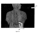
- FIG. IB illustrates gastrointestinal implant device 150 after it has been implanted into the gastrointestinal tract of a mammal using embodiments of the methods and devices of this invention.
- Gastrointestinal implant device comprises a proximal portion or end that includes anchor 152 and a distal portion or end that includes a barrier or sleeve 154.
- the central axis of anchor 152 is substantially aligned with the central axis of the duodenum, allowing chyme to pass through device 150.
- anchor 152 minimizes trauma to the tissue by providing sufficient flexibility and compliance, minimizes the likelihood of tissue erosion, and provides a solid anchoring point to the tissue.
- Anchor 152 can be removably attached within the body using the methods described herein, including the use of barbs attached to, and/or formed on, the anchor itself. In some embodiments, the anchor is attached or secured within the gastrointestinal tract without the use of barbs. When implanted, anchor 152 allows sleeve 154 to be securely implanted within the duodenum, preferably providing a fluid seal at the proximal end.
- the device is anchored in the bulbous duodenum.
- the bulbous duodenum offers several advantages over other areas in of gastrointestinal tract.
- the duodenal bulb is proportionally sized to capture an anchor. That is, it provides a cavity having a relatively large diameter bounded by anatomies having smaller diameters in both the proximal and distal directions.
- the duodenal bulb is naturally configured to retain a suitably shaped anchor.
- the duodenal bulb is relatively less active than either the pylorus or the distal portions of the duodenum. Movement of the surrounding tissue can act to dislodge an anchor over time.
- the duodenal bulb acts as a holding area for chyme received from the stomach.
- the duodenal bulb provides a more stable anchoring platform as there is relatively less movement than at other portions of the gastrointestinal tract.
- the tissue of at least the proximal portion of the duodenal bulb is thicker than the tissue of the distal duodenum, thus, the duodenal bulb provides a better anchoring platform as it is adapted to retain fasteners (e.g., barbs).
- Figures 2A-2Y are a series of sequential diagrams illustrating multiple embodiments of the invention.
- gastro-scope 202 e.g., a 9.8 millimeter endoscope
- Distal end 208 of gastro-scope 202 is directed through pyloric orifice 206 and into proximal duodenum 210, as illustrated in Figure 2B .
- a proximal portion of the small intestine (e.g., the duodenum) is expanded in order to create a working space for the practitioner.
- One method of expanding a proximal portion of the small intestine is to direct a fluid into the duodenum via a working channel in the gastro-scope.
- suitable fluids include gases (e.g., air, nitrogen, and/or carbon dioxide) or liquids (e.g., water and/or saline).
- the fluid is a liquid mixture of saline and a contrast medium.
- Suitable contrast mediums include a fluorescent material, a radiopaque material, or a contrast medium commonly used for intravenous urography (e.g., preparations of diatrizoate sodium and diatrizoate meglumine).
- the liquid is a mixture of about 75% saline and about 25% Renografin TM (available from Bracco Diagnostics, Inc. Corporation, East Princeton, New Jersey).
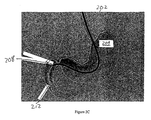
- Figures 2C illustrates fluid 212 as it leaves distal end of 208 of gastro-scope 202.
- the intestinal expansion process is monitored using fluoroscopy to ensure that the fluid is filling the intestines and not flowing proximally into the stomach.
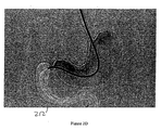
- Figure 2D illustrates the duodenum after it has been expanded to a desired extent with fluid 212.
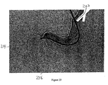
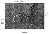
- a length of guidewire 214 is directed through the working channel of gastro-scope 202, out of the distal end 208, and into the proximal portion of the duodenum, as illustrated in Figure 2E .
- An example of a suitable guidewire is about a 3,96 cm (13-foot) length of super- stiff 0.889 mm (0.035 inch) guidewire.
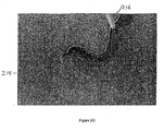
- Guidewire 214 is directed through gastro-scope 202 until the distal end of guidewire 214 forms loop 216 in the duodenum, as shown in Figure 2F .
- the presence and/or location of the loop is confirmed under fluoroscopy.
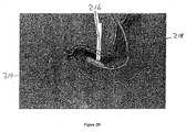
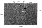
- a delivery catheter is directed into the duodenum, as illustrated in Figures 2G-2I .
- the leading or distal end of outer catheter 218 is attached, assembled to, or comprises a capsule or container assembly that includes capsule or container 216.
- Container 216 defines a guidewire lumen along its side.
- the proximal end of guidewire 214 is directed through the guidewire lumen, and catheter 218 is advanced or directed along guidewire 214 to a point distal from the pylorus and into a desired position in the gastrointestinal tract (e.g., a position distal to the pylorus in the proximal duodenum).
- the location of capsule 216 is confirmed using fluoroscopy.
- the container assembly is advanced into the stomach and the guidewire is removed.
- a gastro-scope is used to direct the container assembly partially or entirely through the pylorus and into the small intestine.
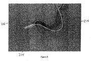
- guidewire 214 can be removed from the gastrointestinal tract, as illustrated in Figures 2J and 2K .
- a lubricating jelly is applied to the surface of those portions of catheter 218 that are inserted into the gastrointestinal tract (e.g., container 216 and the distal portion of outer catheter 218).
- the container holds or houses parts or all of a gastrointestinal implant device (e.g., a gastrointestinal sleeve).
- the gastrointestinal implant device includes a distal portion and a proximal portion.
- the distal portion includes a gastrointestinal sleeve and the proximal portion of the device includes an anchor for securing the device within the gastrointestinal tract (e.g., in the proximal duodenum).
- the container holds or houses the proximal portion of the gastrointestinal device.
- the container holds or houses both the distal and proximal portions.
- the container holds or houses the entire gastrointestinal device. Some or all of the sleeve portion can be folded and stored in the container with the anchor.
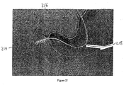
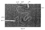
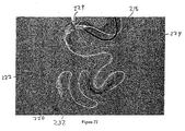
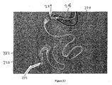
- a distal portion 222 of the sleeve is removed from the container and directed into a location in the gastrointestinal tract that is distal from the container, as illustrated in Figures 2L-2P .
- Outer catheter 218 defines an inner catheter lumen (not illustrated in Figures 2L-2P ) and an inner catheter (not illustrated in Figures 2L-2P ), to which ball 220 is releasably attached, is directed through the inner catheter lumen and into locations of the gastrointestinal tract that are distal from container 216 and pylorus 206.
- Distal portion 222 of the sleeve is releasably secured to the leading or distal portion of the inner catheter so that as the inner catheter is advanced through the distal intestine, distal portion 222 is also advanced. In this manner, distal portion 222 is directed to locations in the gastrointestinal tract that are distal from container 216 and into the distal intestines (e.g., into the jejunum).
- the proximal portion (not illustrated in Figures 2L-2P ) of outer catheter 218 is held in place to ensure that capsule 216 remains in the duodenum and does not move proximally into the stomach.
- the proximal portion of the gastrointestinal sleeve (not illustrated in Figures 2L-2P ) is releasably secured or attached to container 216 by a locking means (e.g., by an anchor locking wire) to ensure that the anchor does not emerge from container 216 and deploy before the distal portion 222 of the sleeve is extended to a desired location in the distal intestines.
- the distal end of the inner catheter includes or is attached to an atraumatic tip (e.g., atraumatic ball 220), which minimizes or eliminates tissue trauma as the inner catheter is advanced into the distal intestines.
- atraumatic tip e.g., atraumatic ball 220
- the exact location to which distal portion 222 is advanced into the distal intestines will vary with the needs of the patient and the demands of the given procedure.
- the inner catheter also includes a stiffening wire that provides sufficient linear or column strength to the inner catheter to facilitates navigation of the distal intestines.
- fluoroscopy is used to track the progress of the advancement.
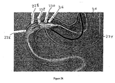
- endoscope 224 is optionally directed into the stomach to visually inspect the proximal end of delivery capsule 216 to ensure that it is in the desired position and/or to monitor the subsequent anchor deployment process, as illustrated in Figures 2O and 2P .
- the inner catheter includes markings which are useful for monitoring the advancement of the inner catheter.
- the outer wall of the inner catheter can include a series of indicia which the practitioner can view as he slides portions of the inner catheter into and out of the outer catheter.
- the inner catheter can include one or more radiopaque markings that can be viewed on an x-ray image or one or more markings that are visible via fluoroscopy.
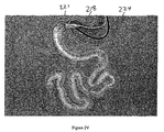
- the anchor After the distal portion of the sleeve is advanced to a desired location in the distal intestines, the anchor is deployed from the container and secured to a desired position within the gastrointestinal tract, as illustrated in Figures 2Q-2S .
- the anchor locking means (not illustrated in Figures 2Q-2S ) is released to allow the anchor to be subsequently removed from container 216.
- the anchor locking means can include a locking wire that releasably secures the anchor within container 216 and pulling the locking wire proximally detaches the anchor so that the anchor can be removed from the container at some subsequent time.
- Container 216 includes visual marker 230 (e.g., a black ring) that can be used to determine if the capsule is in a desired location before anchor 228 is fully removed from container 216 and secured at a desired location in the gastrointestinal tract. For example, delivery catheter 218 is pulled proximally until visual marker 230 is proximal to pylorus 206 and visible in the stomach to endoscope 224. In this manner, the practitioner can ensure that the anchor will deploy at the desired anchoring position when it is removed from container 216.
- visual marker 230 e.g., a black ring
- outer catheter 218 is held in position and the inner catheter is advanced further distally to pull the sleeve and anchor 228 from container 216.
- the anchor is pushed out of the container using a means for displacing an anchor from the container assembly (e.g., an anchor plunger).
- anchor 228 is removed from container 216 and deployed, thereby securing the proximal portion of the device in the gastrointestinal tract (e.g., at the duodenal bulb).
- anchor 228 can secure the device with the use of barbs which extend into the muscle tissue of the proximal duodenum.
- endoscope 224 is optionally removed and/or the stiffening wire is pulled proximally through a main stiffening wire lumen defined by inner catheter 229 and removed from the gastrointestinal tract.
- the sleeve is optionally expanded or inflated by directing fluid through the main stiffening wire lumen defined by inner catheter 229, as illustrated in Figure 2T .
- the fluid causes a distal portion 222 of sleeve to expand and separate or disengage the distal portion of inner catheter 229, as illustrated in Figure 2U .
- Suitable fluids include those discussed previously for use in expanding the duodenum.
- the sleeve can be inflated by directing at least 180 milliliters of a saline solution or a dilute Renografin TM /saline solution.
- Atraumatic ball 220 and distal portion 222 are released from the inner catheter by pulling the locking wire (not illustrated in Figures 2Q-2S ) proximally until a release mark on the wire is visible at the proximal end of outer catheter 218.
- Inner catheter 229 and outer catheter 218 are removed, as illustrated in Figures 2V and 2W .
- the position of the device can be monitored with fluoroscopy while inner catheter 229 and outer catheter 218 are removed from the gastrointestinal tract.
- Atraumatic ball 220 is moved distally via natural peristalsis and is excreted from the gastrointestinal tract.
- the endoscope is positioned across the pylorus and a fluid (e.g., a gas or liquid, such as air, nitrogen, carbon dioxide, saline, or dilute Renografin TM ) is directed into the duodenum to confirm patency of the sleeve, as illustrated in Figure 2X .
- a fluid e.g., a gas or liquid, such as air, nitrogen, carbon dioxide, saline, or dilute Renografin TM
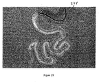
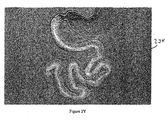
- Figure 2Y illustrates gastrointestinal device 234 placed in the gastrointestinal tract.
- the gastrointestinal implant devices are implanted via catheter-based placements methods (e.g., within endoluminal catheter).
- Figures 3A-3H illustrates multiple embodiments of this invention that include schematic views of various aspects of assembled delivery catheter system 300 for delivery of a gastrointestinal implant device (e.g., a gastrointestinal sleeve).
- delivery catheter system 300 includes an atraumatic tip comprising atraumatic ball 302, a container assembly that includes capsule or container 304, outer catheter 306, inner catheter pusher 308, and inner catheter 310.
- Inner and outer catheters 310, 306 and container 304 are made from materials commonly used to form catheters.
- inner catheter 310 can be made of a polyether block amide (e.g., Pebax ® 7233, available from Arkema Group, Paris, France).
- outer catheter 306 is made of high density polyethylene and/or container 304 is made of hard plastic (e.g., acetal or polycarbonate).
- catheters 310, 306 are made from materials having frictional properties that facilitate the movement of catheter 310 relative to catheter 306 and facilitate the movement of inner catheter 310 and container 304 in the gastrointestinal tract.
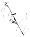
- Figure 3B illustrates a schematic diagram of inner catheter 310.
- Inner catheter 310 includes atraumatic ball locking wire port 314 and stiffening wire port 316 at proximal end 318.
- Figure 3C illustrates a cross-sectional view taken along lines A-A of Figure 3B through one section of inner catheter 310 that is between proximal end 318 and distal end 320.
- Inner catheter 310 defines ball locking wire lumen 322, tension wire lumen 324, and stiffening wire lumen 326.
- Locking wire lumen 322 and stiffening wire lumen 326 extend along the length of, and within, inner catheter 310. Locking wire lumen 322 extends from ball locking wire port 314 to distal end 320.
- Stiffening wire lumen 326 extends along the length of, and within, inner catheter 310, from stiffening wire port 316 to distal end 320.
- Tension wire 328 is located within tension wire lumen 324. The distal and proximal ends of tension wire 328 are attached to the inner walls of tension wire lumen 324, thereby securing tension wire 328 within inner catheter 310.
- tension wire 328 can be attached to the inner walls of tension wire lumen 324 with adhesives, heat setting, or via coextruding inner catheter 310 and tension wire 328.
- Tension wire 328 provides structural support to inner catheter 310.
- tension wire 328 can prevent catheter 310 from undergoing undesired stretching or elongating.
- system 300 includes ball locking wire knob 330 and stiffening wire knob 332.
- Ball locking wire knob 330 extends from ball locking wire port 314 to distal end 302 via ball locking wire lumen 322 (illustrated in Figure 3C ) defined by inner catheter 310.
- Stiffening wire knob 332 extends from stiffening wire port 316 to distal end 302 via stiffening wire lumen 326 (illustrated in Figure 3C ) defined by inner catheter 310.
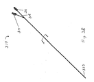
- Figure 3D illustrates a schematic diagram of outer catheter 306 and container 304.
- Container 304 defines guidewire lumen 344.
- Guidewire 356 (illustrated in Figure 3A ) extends along inner and outer catheters 310, 306 and through container 304 via guidewire lumen 344.
- Outer catheter 306 includes anchor locking wire port 336, anchor plunger port 340, and attachment port 342 at proximal end 346.
- Figure 3E illustrates a cross-sectional view taken along lines B-B of Figure 3D through one section of outer catheter 306 that is between proximal end 346 and distal end 348.
- Outer catheter 306 defines inner catheter lumen 350, anchor locking wire lumen 352, and anchor plunger lumen 354.
- Anchor locking wire lumen 352 extends along, and within, outer catheter 306, from anchor locking wire port 336 to distal end 348.
- Anchor plunger lumen 354 extends along, and within, outer catheter 306, from anchor plunger port 340 to distal end 348.
- system 300 includes anchor locking wire 334, a means for displacing an anchor from the container assembly that includes anchor plunger 338, and guidewire 356.
- Anchor locking wire 334 extends from anchor locking wire port 336 to container 304 via anchor locking wire lumen 352 (illustrated in Figure 3E ) defined by outer catheter 306.
- Anchor plunger 338 extends from anchor plunger port 340 to container 304 via anchor plunger lumen 354 (illustrated in Figure 3E ) defined by outer catheter 306.
- System 300 includes inner catheter pusher 308.
- Inner catheter pusher 308 is assembled or attached to outer catheter 306.
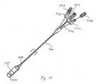
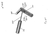
- Figure 3F illustrates a schematic view of inner catheter pusher 308.
- Pusher 308 includes pusher handle 358, slide tube 360, and locking handle 368.
- Pusher handle 358 assembles or attaches pusher 308 to outer catheter 306 (as illustrated in Figure 3A ), thereby connecting pusher 308 to outer catheter 306.
- Pusher 308 defines inner catheter orifice 365, and a slide tube lumen that extends through handle 358, slide tube 360, and locking handle 368.
- Locking handle 368 is attached to slide tube 360 and includes inner catheter locking pads 362 and handle return spring 364. When assembled in system 300, inner catheter 310 extends through slide tube 360 and handle 368 via orifice 365 and the slide tube lumen.
- depressing locking handle 368 causes locking pads 362 to securely grip a portion of inner catheter 310 relative to handle 368 and slide tube 360. Applying force in direction 366 while handle 368 is depressed moves handle 368, tube 360, and inner catheter 310 relative to handle 358, thereby directing a length of inner catheter 310 into the inner catheter lumen defined by the outer catheter.
- handle return spring 364 causes locking pads 362 to disengage from inner catheter 310.
- handle 368 is moved along direction 367, and the process can then be repeated. In this manner, inner catheter 310 can be advanced distally through inner catheter lumen 350 defined by outer catheter 306.
- Slide tube 360 provides rigid support to inner catheter 310 to prevent inner catheter 310 from kinking during advancement.
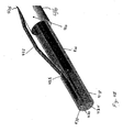
- Figure 3G illustrates a schematic diagram of a portion of system 300 that includes outer catheter 306 and container 304.
- Container 304 defines guidewire lumen 344 and is assembled or attached to distal end 348 of outer catheter 306.
- Container 304 also defines anchor locking wire port 373.
- Catheter 306 defines anchor locking wire ports 370 and 372 which intersect with anchor locking wire lumen 350 (not illustrated in Figure 3G for clarity) defines by outer catheter 306.
- interior walls of container 304 are lined with metal (e.g., with a steel liner).
- Figure 3H illustrates a cross-sectional view taken along lines C-C of Figure 3G through one section of container 304.
- Container 304 defines guidewire lumen 344 as well as inner chamber 305.
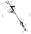
- Figures 4A-4L illustrate additional embodiments of the present invention that include gastrointestinal implant delivery catheter system 400 and a method of use. For purposes of clarity, Figures 4A-4L do not illustrate the various parts and portions of a mammalian gastrointestinal tract.
- System 400 includes an atraumatic tip comprising atraumatic ball 402, a container assembly that includes capsule or container 404, outer catheter 406, inner catheter pusher 408, inner catheter 410, and guidewire 412.
- system 400 is used to place or install a gastrointestinal implant device (e.g., a gastrointestinal sleeve) into the digestive tract of a mammal.
- a gastrointestinal sleeve is releasably secured to the distal end of inner catheter 410 with a locking wire and then the sleeve and an anchor portion is placed or stored within container 404 of a container assembly.
- Guidewire 412 is directed into a desired location within a gastrointestinal tract of a mammal (e.g., in a proximal portion of the small intestine).
- container 404 is directed along the guidewire into a desired location within the mammal's gastrointestinal tract (e.g., the duodenum).
- the distal end of inner catheter 410, along with the secured portion of the gastrointestinal sleeve, is advanced within the gastrointestinal tract to a location that is distal from container 404, thereby extending or unfurling at least a portion of the gastrointestinal sleeve.
- the anchor and the proximal portion of the sleeve is releasably secured within the container assembly with a locking wire.
- the anchor portion is unlocked from the container assembly and removed from the container.
- the anchor can be removed from container 404 by, for example, again advancing inner catheter 410 and the releasably secured distal end of the sleeve, thereby pulling the unlocked anchor from container 404.
- the anchor is removed from container 404 with the use of a means for displacing an anchor from the container assembly that includes anchor plunger 411.
- the anchor is secured at desired location within the gastrointestinal tract of the mammal (e.g., in the duodenum). Any portion of the gastrointestinal implant device that is still secured to system 400 is detached, and the system is removed from the mammal.
- Figure 4A illustrates system 400 with a gastrointestinal sleeve (not visible in Figure 4A ) stored within a container assembly that includes container 404.
- the sleeve includes a distal portion and a proximal portion.
- the proximal portion of the sleeve includes an anchoring device for securing the sleeve to a location within the gastrointestinal tract of a mammal.
- the anchor is placed or stored within a chamber defined by container 404. Some or all of the sleeve is folded and stored within the chamber as well.
- the distal portion of the sleeve is releasable secured to the distal end of inner catheter 410, and the anchor is releasably secured to container 404.
- guidewire 412 After the distal end of guidewire 412 is directed to a desired location within the gastrointestinal tract of a mammal, the proximal end of guidewire 412 is directed through a guidewire lumen defined by container 404.
- outer catheter 406 Once assembled to guidewire 412, outer catheter 406 is advanced to direct container 404 along guidewire 412 and to a desired location within the gastrointestinal tract of the mammal.
- guidewire 412 is removed from the gastrointestinal tract of the mammal.
- Figures 2E-2K illustrate advancement of a container along a guidewire and into the gastrointestinal tract of a mammal.
- Inner catheter pusher 408 is used to direct a distal end of inner catheter 410 into a desired location in the gastrointestinal tract that is distal to container 404.
- Locking handle 414 is depressed, thereby causing the pads (not illustrated in Figure 4A ) of pusher 408 to securely grip inner catheter 410.
- Handle 414 is slid distally, thereby directing a length of inner catheter 410 into the inner catheter lumen (not illustrated in Figure 4A ) defined by outer catheter 406 and causing the distal end 418 of inner catheter 410 to emerge from the distal end of container 404, as shown in Figure 4B .
- Distal portion 420 of sleeve 416 is attached to distal end 418 of inner catheter 410 and is advanced with the inner catheter ( Figures 2L-2P illustrate advancement of an inner catheter and a distal portion of a sleeve). Locking handle 414 is released and the process repeated until a desired length of inner catheter 410 and-intestinal sleeve 416 has been advanced.
- Figure 4B illustrates system 400 after a length of sleeve 416 has been advanced.
- the inner catheter includes an atraumatic tip (e.g., a releasable or deflatable atraumatic ball tip) which facilitates the advancement of the inner catheter through the gastrointestinal tract (e.g., through the proximal intestines).
- the atraumatic tip allows the inner catheter to be advanced through a gastrointestinal tract, while reducing or eliminating damage or irritation to tissue.
- the atraumatic tip guides the inner catheter through the distal intestines.
- the atraumatic ball is in the range of between about 5 millimeters and about 20 millimeters.
- the ball tip is in the range of between about 6.4 millimeters and about 19.2 millimeters in diameter.
- the atraumatic ball is about 12.7 millimeters in diameter.
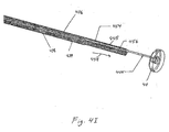
- FIG 4C shows a schematic diagram of the advanced atraumatic tip and distal end 418 of system 400 illustrated in Figure 4B .
- Atraumatic ball 402 is secured to ball retaining wire 424.
- Ball locking wire 422 emerges from a locking wire lumen defined by inner catheter 410 at ball locking wire port 426, extends across a length of inner catheter 410, and passes into the locking wire lumen through ball locking wire port 428.
- the portion of locking wire 422 that extends between locking wire ports 426 and 428 passes through one or more perforations in distal portion 420 of sleeve 416 as well as through ball retaining wire 424, thereby removably securing both distal portion 420 and atraumatic ball 402 to distal end 418 of inner catheter 410.
- Figure 4D illustrates a schematic view of distal end 418 of inner catheter 410 of system 400 with atraumatic ball 402 and retaining wire 424 omitted for clarity.
- Inner catheter 410 defines ball locking wire lumen 430, stiffening wire lumen 434, and tension wire lumen 432.
- Ball locking wire 422 exits ball locking wire lumen via locking wire port 426, extends through distal portion 420 of sleeve 416, and passes back into ball locking wire lumen 430 through locking wire port 428.
- FIG 4E illustrates a cut-away view of the schematic shown in Figure 4D .
- Stiffening wire 436 lies within stiffening wire lumen 434. Stiffening wire 436 facilitates the advancement of the inner catheter through the gastrointestinal tract (e.g., through the-proximal intestines) by, for example, providing a desirable amount of rigidity to the inner catheter so that it can negotiate the gastrointestinal tract.
- the stiffening wire includes a distal portion that is less rigid than other, more proximal, portions. Inclusion of such a stiffening wire provides an inner catheter that has a distal portion that is less rigid than other, more proximal, portions.
- the stiffening wire is used to eject the releasable ball from the end of the inner catheter by advancing the stiffening wire distally relative to the inner catheter.
- the practitioner of the invention can remove the stiffening wire prior to removal of the inner and/or outer catheters, thereby reducing the rigidity of the inner catheter.
- Inner catheter 410 defines tension wire lumen 432.
- the tension wire provides structural support to inner catheter 410 to prevent unwanted deformations of catheter 410 during insertion or maneuverings within a gastrointestinal tract.
- the tension wire can be included to prevent inner catheter 410 from elongating or stretching. Such elongating or stretching can cause locking wire 422 to emerge from port 428 prematurely, thereby releasing distal ball 402 and distal portion 420 from distal end 418 at undesirable portions of a placement procedure.
- Figures 4F-5H illustrate additional embodiments of the invention that include cross sectional views of a portion of container 404.
- container 404 defines storage chamber 407.
- Container 404 includes visual marker 409 which can be used to determine if container 404 is in a desired location before an anchor is fully expelled from container 404.
- Figures 2Q-2S illustrate how a practitioner of the invention uses a visual marker to determine if the container is in a desired location before an anchor is fully removed from the container.
- Container 404 is attached or assembled to outer catheter 406 (a portion of which is omitted from Figures 4F-4H for clarity).
- Anchor pusher wire 444 extends through an anchor pusher wire lumen which is defined by outer catheter 406. The distal end of anchor pusher wire 444 is attached or assembled to anchor pusher plate 411.
- Figure 4G illustrate container 404 and a stored portion of a gastrointestinal device that includes anchor 452 and a proximal portion of sleeve 416.
- Anchor 452 is collapsed or contracted and stored within chamber 407.
- the anchor stored within the chamber(s) defined by a container assembly is a self expanding anchor.
- Anchor 452 is contained or stored in container 404 during portions of a placement method that include directing the container assembly and portions of the gastrointestinal device to various locations within a gastrointestinal tract of a mammal.
- Figures 2H-2P illustrate portions of a placement method that include directing a container assembly and portions of a gastrointestinal device to various locations within a gastrointestinal tract of a mammal.
- the proximal end of the gastrointestinal device includes one or more drawstrings which are attached to the proximal end of the device via perforations in the sleeve material.
- one or more of these drawstrings are used to releasably secure or lock anchor 452 within container 404.
- anchor retaining wire 421 extends out of the proximal end of container 404 via anchor retaining wire port 423 defined by anchor pusher plate 411 and container 404.
- Anchor locking wire 440 extends through anchor locking wire lumen 427 which is defined by outer catheter 406. Wire 440 emerges from lumen 427 via anchor locking wire port 438, extends through drawstring 421, and extends back into lumen 427 via anchor locking wire port 439.
- FIG. 4H illustrates the release of anchor 452 from container 404.
- Anchor locking wire 440 is pulled proximally at anchor locking wire port 438 on the proximal end of outer catheter 406 (not illustrated in Figure 4H ), thereby pulling the distal portion of wire 440 from anchor locking wire port 439 and disengaging wire 440 from anchor retaining wire 421.
- anchor 452 and proximal portion of sleeve 416 are expelled from container 404.
- a practitioner pushes anchor pusher wire 444 distally, thereby directing plate 411 along a direction parallel to direction 458 and forcing anchor 452 from the distal end of container 404.
- inner catheter 410 is advanced further, thereby causing distal portion 420 of sleeve 416 and the attached anchor 452 to advance distally relative to container 404 until anchor 452 emerges from container 404.
- one or more of the chambers of the container assembly is lined with a layer of metal or metal alloy, thereby preventing portions of the anchor from adhering to the inner container walls and facilitating removal of the anchor from the container assembly.
- Figures 2Q-2R illustrate an anchor emerging from a container assembly.
- Pusher plate wire 444 and pusher plate wire lumen 445 includes a mechanism to prevent a practitioner of the invention from directing plate 411 distally to such an extent that plate 411 emerges from the distal end of container 404.
- the mechanism includes moving stop 454 and static stop 456 which have dissimilar diameters. The dissimilar diameters prevent moving stop 454 from translating past static stop 456, thereby preventing excess distal translation of wire 444 relative to outer catheter 406.
- Moving stop 454 is attached to, or formed by a portion of, wire 444 and has an outer diameter that is greater than the outer diameter of the portions of wire 444 that are distal from stop 454. Moving stop 454 moves or translates with wire 444 relative to outer catheter 406 along a direction that is parallel to direction 458.
- Static stop 456 is attached to, or formed by a portion of, outer catheter 406. Stop 456 remains stationary with respect to catheter 406 as wire 444 is translated distally. Static stop 456 defines an inner diameter that is less than the diameter of moving stop 454 but greater than the diameter of the portion of wire 444 that is distal to moving stop 454. Hence, when wire 444 is sufficiently translated distally along a direction parallel to direction 458, moving stop 454 contacts static stop 456, thereby preventing further distal translation of wire 444 along a direction parallel to direction 458. In this manner, the mechanism allows a practitioner of the invention to sufficiently translate plate 411 distally so as to expel a gastrointestinal implant device from a container while simultaneously preventing plate 411 from emerging form the distal end of the container.
- FIG. 4J illustrates system 400 after anchor portion 452 has been expelled from container assembly 404.
- Anchor locking wire 440 has been pulled proximally and away from anchor locking wire port 438 and anchor 452 has expanded after leaving container 404.
- Anchor 452 secures the gastrointestinal device at a desired location within the gastrointestinal tract of a mammal.
- FIG. 4K illustrates the release of ball 402 and distal portion 420 of sleeve 416.
- Ball locking wire 422 is pulled proximally at ball locking wire port 450, thereby pulling the distal portion of ball locking wire 422 from ball locking wire port 428 and disengaging ball locking wire 422 from ball retaining wire 424 and the perforation(s) on distal portion 420 of sleeve 416.
- Ball 402 disengages distal end 418 of inner catheter 410 and is passed through the remainder of the gastrointestinal tract by natural peristalsis.
- a fluid e.g., a gas or liquid
- stiffening wire 436 is no longer needed and can be removed from system 400 by pulling wire 436 proximally at stiffening wire port 446, and removing it entirely from stiffening wire lumen 434.
- a fluid can then be directed through lumen 434 and into sleeve 416, thereby expanding at least a portion of sleeve 416.
- Figure 4L illustrates system 400 after stiffening wire 436 has been removed and a fluid has been directed through stiffening wire port 446, through stiffening wire lumen 434, and into sleeve 416.
- Distal portion 420 of sleeve 416 has been expanded.
- Ball locking wire 422 has been pulled proximally from ball locking wire port 450.
- Figures 2T and 2U illustrates the release of a ball tip from an inner catheter.
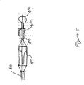
- two capsules or containers are used to deliver or place a gastrointestinal device into a mammal.
- Figure 5 illustrates one embodiment of a two-capsule delivery device that includes first container 602, second container 604, atraumatic ball 606, and sleeve 608 of a gastrointestinal implant device.
- a proximal portion of the gastrointestinal implant device, which includes an anchor, is stored in first container 602.
- a distal portion of the device, which includes sleeve 608, is stored within second container 604.
- Second container 604 or a portion of second container 604 fits coaxially inside of first container 602.
- Such a two-capsule embodiment is useful for reducing the amount of drag experienced when extending the sleeve portion of a gastrointestinal device through the distal intestines. This is because second container 604 is moving relative to the intestinal wall, while the portion of the sleeve that has been extended is relatively stationary with respect to the intestinal wall. In other words, rather than dragging the entire length of the extended sleeve material along the intestinal tract, essentially only second container 604 is moved relative to the intestinal wall. This reduces the amount of friction experienced when a practitioner of the invention extends the sleeve portion during a placement procedure of the invention.
- Second container 604 including sleeve 608 is then placed inside of first container 602.
- First container 602 is attached to outer catheter 610 and inserted into the proximal duodenum.
- Second container 604 is attached to the distal end of the inner catheter.
- Second container 604 is advanced into the distal intestine along with the distal end of inner catheter and atraumatic ball 606. As second container 604 is advanced, sleeve 608 is released from the proximal end of second container 604.
- the distal end of sleeve 608 is unlocked from the first container.
- the anchor is then released from first container 602 and the device is secured within the gastrointestinal tract.
- the second container and atraumatic ball are passed through the digestive tract via natural peristalsis.
- the second container and the atraumatic ball are formed from a single piece of material.
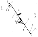
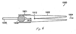
- FIG. 6 is a cross-section of everting catheter system 1900 for delivery of a longer unsupported flexible sleeve 1902.
- a gastrointestinal implant device is shown with sleeve anchor 1901 and attached sleeve 1902 shown as delivered into the anatomy.
- Balloon catheter 1906 is introduced into sleeve anchor 1901 and balloon 1908 inflated to seal the lumen of anchor 1901.
- Sleeve 1902 is folded inside itself and elastic band 1912 is used to-seal the end of the sleeve.
- Fluid is then injected through balloon catheter shaft 1906 into sleeve lumen 1910, filling the lumen and pressurizing it. The pressure of the fluid is used to push the inner sleeve distally towards 1904.
- elastic band 1912 falls off of the closed end of sleeve 1902 and passes distally in the intestine until it is excreted.
- This mechanism permits deployment of a sleeve that is longer than (e.g., double) the length of the delivered device. This may be needed as it is difficult to access the distal parts of the intestine with guidewires.
- everting catheter system 1900 enables delivery of longer sleeves than are possible using some of the other delivery catheters described herein.
- Figures 7A-7C illustrate embodiments for attaching a releasable atraumatic element to the distal end of a delivery catheter.
- Figure 7A is a schematic view of the distal end of the catheter system illustrating a releasable ball tip mechanism.
- a sleeve retention wire 4208 travels through second lumen 4204 in catheter shaft 4200, exits second lumen 4204 through proximal skive hold 4218 and re-enters the second lumen through distal skive hole 4216.
- a wire, or thread 4600 are attached to ball 4218 and thread 4600 is looped through sleeve retention wire 4208 to hold ball 4218 at the distal end of inner shaft 4200 of the catheter.
- Ball 4218 is released by pulling back on sleeve retention wire 4208 with fitting 4200 ( Figure 7A ) until thread 4600 is no longer held by sleeve retention wire 4208. Ball 4218 then falls off the distal end of the inner shaft of catheter 4200 and exits the body through normal peristalsis through the intestines.
- Figure 7B is a schematic view of the distal end of the catheter illustrating an alternative embodiment of a releasable ball tip mechanism.
- Inner shaft 4200 fits in recess 4706 in ball 4218.
- Sleeve retention wire 4208 exits inner shaft 4200 through proximal skive hole 4214, pierces the sleeve and re-enters inner shaft 4200 through distal proximal skive hole 4216.
- the distal end of sleeve retention wire 4208 is formed into coil shape 4700 and sits in pocket 4702 in ball 4218.
- Pocket 4702 is connected to recess 4702 through hole 4704, which is of a smaller diameter than recess 4702 and pocket 4700.
- the distal end of sleeve retention wire 4208 can include a shape memory metal or metal alloy so that sleeve retention wire 4208 can be deformed and still return to approximately its original shape. In this way, wire 4208 can be assemble wire 4208 to ball 4218 and then the distal end of wire 4208 can regain its coiled shape to hold ball 4218 to the end of shaft 4200. Furthermore, wire 4208 can be can be pulled back in a proximal direction, the distal end of wire 4208 will straighten (thereby allowing the distal end of wire 4208 to be removed through hole 4704), and ball 4218 will be released from the end of shaft 4200.
- Figure 7C is yet another embodiment of a releasable ball tip mechanism.
- Inner shaft 4200 fits in recess 4706 in ball 4218.
- Sleeve retention wire 4208 exits inner shaft 4200 through proximal skive hole 4214, pierces the sleeve and re-enters the inner shaft 4200 through distal proximal skive hole 4216.
- Ball 4218 includes two holes 4800, 4802 extending from recess 4706 to exterior surface of ball 4218.
- the distal end of sleeve retention wire 4208 passes through hole 166 and is looped back into hole 167.
- wire 4218 is pulled back through hole 4802 and then through hold 4800 and ball 4218 is released from the distal end of the catheter.
- Figure 8 is a cross sectional view of an alternative embodiment of a solid spherical shaped atraumatic element.
- Ball 4900 is fabricated in two halves, 4902 and 4904.
- Sleeve retention wire 4006 fits into S-shaped track 4908.
- the S shape of track 4908 creates sufficient friction to hold the ball on the end of the catheter during delivery of the gastrointestinal implant device.
- Sleeve retention wire 4600 fits snugly in channel 4908 but can be pulled proximally to release sleeve retention wire 4600 from ball 4900.
- the catheter shaft fits in recess 4906.
- a delivery catheter e.g., an inner catheter
- the distal end of a delivery catheter can includes an atraumatic tip comprising a low profile balloon instead of a releasable ball.
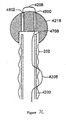
- Figures 9A-9B is a sectional view of the distal end of a delivery catheter fitted with a low profile balloon.
- Figure 9A is a schematic view of the distal end of the catheter within an inflatable spherical shaped element.
- Figure 9B is a schematic view of the distal end of the catheter after the inflatable spherical shaped element has been inflated;
- sleeve 5012 is attached to the distal end of catheter shaft 4302.
- Filling holes 5010 connect with the inner lumen of the catheter to provide a passage for inflation of an inflatable spherical shaped element (balloon) 5008.
- Balloon 5008 is attached to shaft 4302 with metal band 5000 that has tapered proximal transition 5002 to minimize edges that could catch on sleeve 5012 after delivery of sleeve 5012.
- Metal band 5000 is about 0.003 - 0.005 inches ( ⁇ 0.076 to ⁇ 0.127 mm) thick.
- Balloon 5008 can be thin wall molded, tubular polyurethane or silicone.
- the balloon is stored along distal catheter shaft 4302 with the distal end pushed into the lumen of the catheter shaft and attached to catheter shaft 4302 with plug 5006 to keep the balloon from expanding beyond the tip of the catheter.
- Figure 9B illustrates the distal end of catheter 4302 after balloon 5002 has been expanded into a near-spherical shape.
- the balloon is expanded by fluid, which flows through the catheter shaft and enters balloon 5008 through the fluid passage holes from the catheter shaft.
- Plug 5006 at the end of the catheter shaft ensures that the balloon acts like the ball shown in the embodiment in Figure 9B by limiting expansion of the balloon beyond the tip of the catheter, and the plug also provides some lateral strength to the balloon.
Abstract
Description
- Obesity is an overwhelming health problem. According to the Center for Disease Control (CDC), over sixty percent of the United States population is overweight, and almost twenty percent are obese. This translates into about 40 million adults in the United States with a Body Mass Index (BMI) of 30 or above. The BMI is defined as a person's weight (in kilograms) divided by height (in meters), squared. To be considered clinically, morbidly obese, one must meet one of three criteria: a Body Mass Index of more than 35, 45.36 kg (one hundred pounds) overweight, or 100% above ideal body weight. There is also a category for the super-obese for those weighing over 158.8 kg (350 lbs).
- Carrying this excess weight places enormous strain upon a person's body; organs are affected, as are the nervous and circulatory systems. In 2000, the National Institute of Diabetes, Digestive and Kidney Diseases (NIDDK) estimated that there were 280,000 deaths directly related to obesity. The NIDDK further estimated that the direct cost of healthcare in the US associated with obesity is $51 billion. In addition, Americans spend $33 billion per year on weight loss products. In spite of this economic cost and consumer commitment, the prevalence of obesity continues to rise at alarming rates. From 1991 to 2000, obesity rates in the US grew by 61 % and worldwide obesity rates also increased dramatically.
- One of the principle costs to the healthcare system stems from the co-morbidities associated with obesity. Incidence of Type-2 diabetes has climbed to 7.3% of the population. Of those persons with Type-2 diabetes, almost half are clinically obese, and two thirds are approaching obese. Other co-morbidities include hypertension, coronary artery disease, hypercholesteremia, sleep apnea and pulmonary hypertension.
- Although the physiology and psychology of obesity are complex, the medical consensus is that the cause is quite simple: over consumption of calories combined with a reduction in energy expenditures seen in modem society. While the treatment seems quite intuitive, the institution of a cure is a complex issue that has so far vexed the best efforts of medical science. Dieting is not an adequate long-term solution for most people. Once an individual has slipped past the BMI of 30, significant changes in lifestyle are the only solution.
- There have been many attempts in the past to surgically modify patients' anatomies to attack the consumption problem by reducing the desire to eat. Stomach saplings, or gastroplasties, to reduce the volumetric size of the stomach, therein achieving faster satiety, were performed in the 1980's and early 1990's. Although able to achieve early weight loss, sustained reduction was not obtained. The reasons are not all known, but are believed related to several factors. One of which is that the stomach stretches over time increasing volume while psychological drivers motivate patients to find creative approaches to literally eat around the smaller pouch.
- There are currently two surgical procedures that successfully produce long-term weight loss; the Roux-en-Y gastric bypass and the biliopancreatic diversion with duodenal switch (BPD). Both procedures reduce the size of the stomach plus shorten the effective-length of intestine available for nutrient absorption. Reduction of the stomach size reduces stomach capacity and the ability of the patient to take in food. Bypassing the duodenum makes it more difficult to digest fats, high sugar and carbohydrate rich foods. One objective of the surgery is to provide feedback to the patient by producing a dumping syndrome if they do eat these food products. Dumping occurs when carbohydrates directly enter the jejunum without being first conditioned in the duodenum. The result is that a large quantity of fluid is discharged into the food from the intestinal lining. The total effect makes the patient feel light-headed and results in severe diarrhea. For reasons that have not been determined the procedure also has an immediate therapeutic effect on diabetes.
- Although the physiology seems simple, the exact mechanism of action in these procedures is not understood. Current theory is that negative feedback is provided from both regurgitation into the esophagus and dumping when large volumes of the wrong foods are eaten. Eventually, patients learn that to avoid both these issues they must be compliant with the dietary restrictions imposed by their modified anatomy. In the BPD procedure, large lengths of jejunum are bypassed resulting in malabsorption and therefore, reduced caloric uptake. In fact, the stomach is not reduced in size as much in the BPD procedure so that the patient is able to consume sufficient quantities of food to compensate for the reduced absorption. This procedure is reserved for the most morbidly obese as there are several serious side effects of prolonged malabsorption.
- Unfortunately, these procedures carry a heavy toll. The morbidity rate for surgical procedures is alarmingly high with 11 % requiring surgical intervention for correction. Early small bowel obstruction occurs at a rate of between 2-6% in these surgeries and mortality rates are reported to be approximately 0.5 -1.5%. While surgery seems to be an effective answer, the current invasive procedures are not acceptable with these complication rates. Laparoscopic techniques applied to these surgeries provide fewer surgical complications but continue to expose these very ill patients to high operative risk in addition to requiring an enormous level of skill by the surgeon. Devices to reduce absorption in the small intestines have been proposed (See
U.S. Patent Number 5,820,584 (Crabb ),U.S. Patent Number 5,306,300 (Berry ) andU.S. Patent Number 4,315,509 (Smit )). However, these devices have not been successfully implemented. -
WO2004/049982 discloses a method and apparatus for limiting absorption of food products in specific parts of the digestive system. A gastrointestinal device includes an anchor and a flexible sleeve. The anchor is collapsible for endoscopic delivery and removal. - Recently, various gastrointestinal implants have been developed as potential solutions to these above problems. However, a need exists for methods and devices to place or position these implants within mammalian gastrointestinal tracts.
- According to the present invention there is provided a delivery system for placing a gastrointestinal implant device in a mammalian gastrointestinal tract according to
claim 1. - This invention can be used in methods for implanting or placing a gastrointestinal implant device (e.g., a gastrointestinal sleeve) into the gastrointestinal tract of a mammal (e.g., a human). The methods utilize, and the devices include, a container assembly and a gastrointestinal implant device having a proximal end that includes an anchor and a distal end that includes a sleeve.
- This invention can be used in methods of placing a gastrointestinal implant device in a mammal. The gastrointestinal implant device includes an anchor and a flexible, floppy, thin, conformable, and/or collapsible sleeve. In some arrangements, the method comprises the steps of placing a gastrointestinal implant device in a container assembly, directing the container assembly into a mammalian gastrointestinal tract, removing the device from the container assembly, and securing the anchor to a location in the gastrointestinal tract. In some arrangements, the step of removing the device from the container assembly includes directing a portion of the sleeve to a location in the gastrointestinal tract that is distal relative to the assembly while the anchor is releasably secured in the container assembly.
- In some arrangements, at least a portion of the sleeve is removed from the container assembly before the anchor is removed from the container. Optionally, the anchor is releasably secured in the container assembly while at least a portion of the sleeve is directed to a location in the gastrointestinal tract that is distal from the container assembly. The sleeve can be directed into the location by, for example, advancing a catheter having an atraumatic tip. In further embodiments, a distal portion of the catheter is less rigid than a proximal portion of the catheter.
- In some arrangements, the container is directed to the duodenum of the gastrointestinal tract. In further arrangements, at least a portion of the sleeve is directed into the jejunum of the gastrointestinal tract. Optionally, the anchor is self-expanding and/or is secured in the duodenum of the gastrointestinal tract.
- In some arrangements, the method further includes a step of directing a fluid (e.g., a gas and/or liquid) into the gastrointestinal tract. The fluid can be directed into the tract before and/or after the container assembly is directed into the duodenum. The fluid can be used, for example, to expand at least a portion of the gastrointestinal tract and/or to deploy or expand portions of the gastrointestinal implant device. Examples of suitable fluids include gasses (e.g., air, carbon dioxide, and/or nitrogen) and liquids (e.g., saline and mixtures of liquid saline and a contrast medium). In some arrangements, at least 60 milliliters of fluid are directed into the gastrointestinal tract.
- In some arrangements, the container assembly includes a first chamber and the step of placing the device in the assembly includes storing the anchor in the first chamber. Optionally, the step of removing the device from the assembly includes directing at least a portion of the sleeve to a location in the gastrointestinal tract that is distal relative to the first chamber while the anchor is releasably secured in the first chamber. In further arrangements, the container assembly further includes a second chamber and the step of placing the device in the assembly includes storing at least a portion of the sleeve in the second chamber. Optionally, the step of removing the device from the assembly includes directing the second chamber to a location in the gastrointestinal tract that is distal relative to the first chamber while the anchor is releasably secured in the first chamber and the sleeve is releasably secured in the second chamber.
- This invention also includes delivery systems for placing a gastrointestinal implant device in a mammalian gastrointestinal tract. In some embodiments of the invention, the delivery systems comprise a container assembly and a gastrointestinal implant device. The implant device includes a proximal end and a distal end, and the proximal end includes an anchor and the distal end includes a sleeve. The proximal end and the distal end are stored within the container assembly.
- In further embodiments, the systems include an anchor locking mechanism located within the assembly. The anchor locking mechanism can include an anchor locking wire that extends through a portion of the device. The system can further include a means for displacing an anchor from the container assembly (e.g., an anchor plunger). Optionally, the anchor is self-expanding. The exterior portion of the container assembly can include a visible marker for positioning the assembly within the gastrointestinal tract of a mammal.
- The systems further include a catheter releasably secured to the distal end of the sleeve. The catheter can include an atraumatic tip (e.g., a releasable ball) and/or a distal portion of the catheter can be less rigid than a proximal portion of the catheter.
- In some embodiments, wherein the assembly includes a first chamber and a second chamber, the first chamber storing at least a portion of the proximal end and the second chamber storing at least a portion of the distal end. In further embodiments, at least a portion of the second chamber is stored in the first chamber.
- The foregoing and other objects, features and advantages of the invention will be apparent from the following more particular description of preferred embodiments of the invention, as illustrated in the accompanying drawings in which like reference characters refer to the same parts throughout the different views. The drawings are not necessarily to scale, emphasis instead being placed upon illustrating the principles of the invention.
-
Figure 1A is a sectional view of a portion of the digestive tract in a mammalian body. -
Figure 1B illustrates a gastrointestinal implant device after it has been implanted into the gastrointestinal tract of a mammal. -
Figures 2A-2Y are a series of sequential diagrams illustrating multiple embodiments of methods of the invention. -
Figures 3A-3H illustrates multiple embodiment of this invention that includes a schematic view of assembled delivery catheter systems for delivery of gastrointestinal implant devices (e.g., gastrointestinal sleeves). -
Figures 4A-4L illustrate additional embodiments of the invention that include a gastrointestinal implant delivery catheter system and a method of use. -
Figure 5 illustrates an embodiment of a two-capsule delivery device that includes a first container, a second container, an atraumatic ball, and a sleeve of a gastrointestinal implant device. -
Figure 6 illustrates a cross-section of an everting catheter system for delivery of a sleeve. -
Figures 7A-7C illustrate embodiments for attaching a releasable atraumatic element to the distal end of a delivery catheter. -
Figure 8 illustrates a cross sectional view of an alternative embodiment of a solid spherical shaped atraumatic element. -
Figures 9A-9B illustrate sectional views of the distal ends of delivery catheters fitted with a low profile balloon. - A description of preferred embodiments of the invention follows. While this invention has been particularly shown and described with references to preferred embodiments thereof, it will be understood by those skilled in the art that various changes in form and details may be made therein without departing from the scope of the invention encompassed by the appended claims.
- This invention features devices for implanting or placing gastrointestinal implant devices (e.g., intestinal sleeves) into mammals (e.g., a human). Several gastrointestinal implant devices (e.g., intestinal sleeves) have been developed and are suitable for implementation or placement within a gastrointestinal tract using the methods and devices of this invention. Some examples of such devices are described in
U.S. Patent Application No. 10/339,786, filed January 9, 2003 U.S. Patent Application No. 10/726,011, filed December 2, 2003 U.S. Patent Application No. 10/810,317, filed March 26, 2004 U.S. Patent Application No. 10/811 ,293, filed March 26, 2004 U.S. Patent Application No. 10/858,852, filed June 1, 2004 U.S. Provisional Application No. 60/544,527, filed February 13, 2004 U.S. Patent Application No. 10/858,851, filed June 1, 2004 U.S. Patent Application No. 60/61 1,038, filed September 17, 2004 U.S. Provisional Application No. 60/645,296, filed on January 19, 2005 U.S. Provisional Application No. 60/645,287, filed January 19, 2005 - Figure IA is a sectional view of a portion of the digestive tract in a mammalian body. Food to be digested enters the
stomach 102 through thecardiac orifice 110 from the esophagus. Chyme, a semi-fluid, homogeneous creamy or gruel-like material produced by gastric digestion in the stomach exits the stomach through the pyloric orifice orpylorus 108 and enters the small intestine. - The
pylorus 108 is a distal aperture of thestomach 102 surrounded by a strong band of circular muscle. The small intestine, about 4.57-6.10 m (15-20 feet) in length, is a convoluted tube, extending from thepylorus 108 to the ileo-caecal valve where it terminates in the large intestine. The small intestine has three sections, theduodenum 104,jejunum 106 and the ileum (not shown inFigure 1 ). Theduodenum 104 makes up the first 25.4-30.5 cm (10-12 inch) section of the small intestine and tends to be the shortest, widest, and most fixed part of the small intestine. - The
duodenum 104 has four sections which typically form a U shape: superior, descending, transverse, and ascending. The superior section is about two inches long and ends at the neck of the gall bladder. The superior section also defines a feature referred to as theduodenal bulb 119 that begins just distal to thepylorus 108 and extends for about 2.54 to 3.81 cm (1 to 1.5 inches) in an adult human. Theduodenal bulb 1 19 defines a lumen therein that is slightly larger than thedistal duodenum 104. Advantageously, theduodenal bulb 119 exhibits less motion than thepylorus 108 and even distal portions of theduodenum 104. Notably, the motion is substantially limited to contractions without having a significant linear component (i.e., no movement along the central axis of the intestine). The tissue of the intestinal wall of thepylorus 108, and to some extent that of theduodenal bulb 1 19, tends to be thicker than that of other portions of the small intestine, but the tissue thins as one moves away from thepylorus 108. - The descending section of the
duodenum 104 is about three to four inches long and includes a nipple shaped structure, the papilla ofVater 1 14, through which pancreatic juice from the pancreas and bile produced by the liver and stored by the gall bladder enter the duodenum from the pancreatic and bile ducts. The pancreatic juice contains enzymes essential to protein digestion and bile dissolves the products of fat digestion. The ascending section is about 5.08 cm (two inches) long and forms the duodenal-jejunal flexure 116 where it joins thejejunum 106, the next section of the small intestine. The duodenaljejunal flexure 1 16 is fixed to the ligament of Treitz 118 (musculus supensionus duodeni). The juices secreted in the duodenum break the partially digested food down into particles small enough to be absorbed by the body. The digestive system is described in Gray's Anatomy ("Anatomy of the Human Body," by Henry Gray) and "Human Physiology," Vander, 3rd ed, McGraw Hill, 1980. - This invention includes devices for placing or implanting a gastrointestinal implant device in a mammal. For example, this invention includes devices for implanting a gastrointestinal sleeve. In some embodiments, the gastrointestinal sleeve includes an anchor portion and a floppy, flexible, thin, conformable, and/or collapsible sleeve portion.
- Figure IB illustrates gastrointestinal implant device 150 after it has been implanted into the gastrointestinal tract of a mammal using embodiments of the methods and devices of this invention. Gastrointestinal implant device comprises a proximal portion or end that includes anchor 152 and a distal portion or end that includes a barrier or
sleeve 154. When implanted, as shown in Figure IB, the central axis of anchor 152 is substantially aligned with the central axis of the duodenum, allowing chyme to pass through device 150. Additionally, anchor 152 minimizes trauma to the tissue by providing sufficient flexibility and compliance, minimizes the likelihood of tissue erosion, and provides a solid anchoring point to the tissue. - Anchor 152 can be removably attached within the body using the methods described herein, including the use of barbs attached to, and/or formed on, the anchor itself. In some embodiments, the anchor is attached or secured within the gastrointestinal tract without the use of barbs. When implanted, anchor 152 allows
sleeve 154 to be securely implanted within the duodenum, preferably providing a fluid seal at the proximal end. - In some embodiments, the device is anchored in the bulbous duodenum. For purposes of anchoring a gastrointestinal device, the bulbous duodenum offers several advantages over other areas in of gastrointestinal tract. First, the duodenal bulb is proportionally sized to capture an anchor. That is, it provides a cavity having a relatively large diameter bounded by anatomies having smaller diameters in both the proximal and distal directions. Thus, the duodenal bulb is naturally configured to retain a suitably shaped anchor. Additionally, the duodenal bulb is relatively less active than either the pylorus or the distal portions of the duodenum. Movement of the surrounding tissue can act to dislodge an anchor over time. The duodenal bulb, at least in part, acts as a holding area for chyme received from the stomach. Thus, the duodenal bulb provides a more stable anchoring platform as there is relatively less movement than at other portions of the gastrointestinal tract. Still further, the tissue of at least the proximal portion of the duodenal bulb is thicker than the tissue of the distal duodenum, thus, the duodenal bulb provides a better anchoring platform as it is adapted to retain fasteners (e.g., barbs).
-
Figures 2A-2Y are a series of sequential diagrams illustrating multiple embodiments of the invention. InFigure 2A , gastro-scope 202 (e.g., a 9.8 millimeter endoscope) is directed through the mouth of a patient, and intostomach 204.Distal end 208 of gastro-scope 202 is directed throughpyloric orifice 206 and intoproximal duodenum 210, as illustrated inFigure 2B . - Optionally, a proximal portion of the small intestine (e.g., the duodenum) is expanded in order to create a working space for the practitioner. One method of expanding a proximal portion of the small intestine is to direct a fluid into the duodenum via a working channel in the gastro-scope. Examples of suitable fluids include gases (e.g., air, nitrogen, and/or carbon dioxide) or liquids (e.g., water and/or saline). In some embodiments, the fluid is a liquid mixture of saline and a contrast medium. Examples of suitable contrast mediums include a fluorescent material, a radiopaque material, or a contrast medium commonly used for intravenous urography (e.g., preparations of diatrizoate sodium and diatrizoate meglumine). In still further embodiments, the liquid is a mixture of about 75% saline and about 25% Renografin™ (available from Bracco Diagnostics, Inc. Corporation, East Princeton, New Jersey).
- The exact amount of fluid needed to sufficiently expand the duodenum will depend on variables such as the size of the patient's gastrointestinal tract, the preferences of the practitioner, and/or the length of the gastrointestinal device to be delivered. In some embodiments, at least 60 milliliters of a fluid are used to expand the duodenum. In further embodiments, at least 200 milliliters of a fluid are used to expand the duodenum. 200 milliliters of a fluid would be useful for delivering, for example, a gastrointestinal sleeve that is about two feet in length. In further embodiments, at least 500 milliliters of a fluid are used to expand the duodenum. In still further embodiments, about 600 milliliters of a fluid are used to expand the duodenum which would be useful for delivering, for example, a gastrointestinal sleeve that is about 4 feet in length, (1 foot=30,5cm).
-
Figures 2C illustrates fluid 212 as it leaves distal end of 208 of gastro-scope 202. Optionally, the intestinal expansion process is monitored using fluoroscopy to ensure that the fluid is filling the intestines and not flowing proximally into the stomach.Figure 2D illustrates the duodenum after it has been expanded to a desired extent withfluid 212. - After the small intestine has been expanded to the desired extent, a length of
guidewire 214 is directed through the working channel of gastro-scope 202, out of thedistal end 208, and into the proximal portion of the duodenum, as illustrated inFigure 2E . An example of a suitable guidewire is about a 3,96 cm (13-foot) length of super- stiff 0.889 mm (0.035 inch) guidewire.Guidewire 214 is directed through gastro-scope 202 until the distal end ofguidewire 214forms loop 216 in the duodenum, as shown inFigure 2F . Optionally, the presence and/or location of the loop is confirmed under fluoroscopy. Once a sufficient length ofguidewire 214 is in the desired location, gastro-scope 202 can be removed whileguidewire 214 is held in position. - Once the guidewire is in the desired location and the gastro-scope has been removed, a delivery catheter is directed into the duodenum, as illustrated in
Figures 2G-2I . The leading or distal end ofouter catheter 218 is attached, assembled to, or comprises a capsule or container assembly that includes capsule orcontainer 216.Container 216 defines a guidewire lumen along its side. The proximal end ofguidewire 214 is directed through the guidewire lumen, andcatheter 218 is advanced or directed alongguidewire 214 to a point distal from the pylorus and into a desired position in the gastrointestinal tract (e.g., a position distal to the pylorus in the proximal duodenum). Optionally, the location ofcapsule 216 is confirmed using fluoroscopy. - Alternatively, the container assembly is advanced into the stomach and the guidewire is removed. A gastro-scope is used to direct the container assembly partially or entirely through the pylorus and into the small intestine.
- Once
container 216 is at the desired location in the duodenum, guidewire 214 can be removed from the gastrointestinal tract, as illustrated inFigures 2J and2K . Optionally, prior to insertion, a lubricating jelly is applied to the surface of those portions ofcatheter 218 that are inserted into the gastrointestinal tract (e.g.,container 216 and the distal portion of outer catheter 218). - The container holds or houses parts or all of a gastrointestinal implant device (e.g., a gastrointestinal sleeve). The gastrointestinal implant device includes a distal portion and a proximal portion. The distal portion includes a gastrointestinal sleeve and the proximal portion of the device includes an anchor for securing the device within the gastrointestinal tract (e.g., in the proximal duodenum). In some embodiments, the container holds or houses the proximal portion of the gastrointestinal device. In other embodiments, the container holds or houses both the distal and proximal portions. According to the invention, the container holds or houses the entire gastrointestinal device. Some or all of the sleeve portion can be folded and stored in the container with the anchor.
- After
container 216 is at the desired location in the proximal duodenum, adistal portion 222 of the sleeve is removed from the container and directed into a location in the gastrointestinal tract that is distal from the container, as illustrated inFigures 2L-2P .Outer catheter 218 defines an inner catheter lumen (not illustrated inFigures 2L-2P ) and an inner catheter (not illustrated inFigures 2L-2P ), to whichball 220 is releasably attached, is directed through the inner catheter lumen and into locations of the gastrointestinal tract that are distal fromcontainer 216 andpylorus 206. -
Distal portion 222 of the sleeve is releasably secured to the leading or distal portion of the inner catheter so that as the inner catheter is advanced through the distal intestine,distal portion 222 is also advanced. In this manner,distal portion 222 is directed to locations in the gastrointestinal tract that are distal fromcontainer 216 and into the distal intestines (e.g., into the jejunum). - As the inner catheter is advanced through the inner catheter lumen and into the distal intestine, the proximal portion (not illustrated in
Figures 2L-2P ) ofouter catheter 218 is held in place to ensure thatcapsule 216 remains in the duodenum and does not move proximally into the stomach. The proximal portion of the gastrointestinal sleeve (not illustrated inFigures 2L-2P ) is releasably secured or attached tocontainer 216 by a locking means (e.g., by an anchor locking wire) to ensure that the anchor does not emerge fromcontainer 216 and deploy before thedistal portion 222 of the sleeve is extended to a desired location in the distal intestines. - The distal end of the inner catheter includes or is attached to an atraumatic tip (e.g., atraumatic ball 220), which minimizes or eliminates tissue trauma as the inner catheter is advanced into the distal intestines. The exact location to which
distal portion 222 is advanced into the distal intestines will vary with the needs of the patient and the demands of the given procedure. The inner catheter also includes a stiffening wire that provides sufficient linear or column strength to the inner catheter to facilitates navigation of the distal intestines. Optionally, fluoroscopy is used to track the progress of the advancement. - After the desired length of sleeve has been delivered,
endoscope 224 is optionally directed into the stomach to visually inspect the proximal end ofdelivery capsule 216 to ensure that it is in the desired position and/or to monitor the subsequent anchor deployment process, as illustrated inFigures 2O and2P . Optionally, the inner catheter includes markings which are useful for monitoring the advancement of the inner catheter. For example, the outer wall of the inner catheter can include a series of indicia which the practitioner can view as he slides portions of the inner catheter into and out of the outer catheter. In addition or alternatively, the inner catheter can include one or more radiopaque markings that can be viewed on an x-ray image or one or more markings that are visible via fluoroscopy. - After the distal portion of the sleeve is advanced to a desired location in the distal intestines, the anchor is deployed from the container and secured to a desired position within the gastrointestinal tract, as illustrated in
Figures 2Q-2S . The anchor locking means (not illustrated inFigures 2Q-2S ) is released to allow the anchor to be subsequently removed fromcontainer 216. For example, the anchor locking means can include a locking wire that releasably secures the anchor withincontainer 216 and pulling the locking wire proximally detaches the anchor so that the anchor can be removed from the container at some subsequent time. -
Container 216 includes visual marker 230 (e.g., a black ring) that can be used to determine if the capsule is in a desired location beforeanchor 228 is fully removed fromcontainer 216 and secured at a desired location in the gastrointestinal tract. For example,delivery catheter 218 is pulled proximally untilvisual marker 230 is proximal topylorus 206 and visible in the stomach toendoscope 224. In this manner, the practitioner can ensure that the anchor will deploy at the desired anchoring position when it is removed fromcontainer 216. - Once
container 216 is in the desired location,outer catheter 218 is held in position and the inner catheter is advanced further distally to pull the sleeve and anchor 228 fromcontainer 216. Optionally, the anchor is pushed out of the container using a means for displacing an anchor from the container assembly (e.g., an anchor plunger). - As shown in
Figures 2Q-2S ,anchor 228 is removed fromcontainer 216 and deployed, thereby securing the proximal portion of the device in the gastrointestinal tract (e.g., at the duodenal bulb). For example,anchor 228 can secure the device with the use of barbs which extend into the muscle tissue of the proximal duodenum. - After
anchor 228 is deployed and the device secured within the gastrointestinal tract,endoscope 224 is optionally removed and/or the stiffening wire is pulled proximally through a main stiffening wire lumen defined byinner catheter 229 and removed from the gastrointestinal tract. After the stiffening wire has been removed, the sleeve is optionally expanded or inflated by directing fluid through the main stiffening wire lumen defined byinner catheter 229, as illustrated inFigure 2T . The fluid causes adistal portion 222 of sleeve to expand and separate or disengage the distal portion ofinner catheter 229, as illustrated inFigure 2U . Suitable fluids include those discussed previously for use in expanding the duodenum. For example, the sleeve can be inflated by directing at least 180 milliliters of a saline solution or a dilute Renografin™/saline solution.Atraumatic ball 220 anddistal portion 222 are released from the inner catheter by pulling the locking wire (not illustrated inFigures 2Q-2S ) proximally until a release mark on the wire is visible at the proximal end ofouter catheter 218. -
Inner catheter 229 andouter catheter 218 are removed, as illustrated inFigures 2V and2W . Optionally, the position of the device can be monitored with fluoroscopy whileinner catheter 229 andouter catheter 218 are removed from the gastrointestinal tract.Atraumatic ball 220 is moved distally via natural peristalsis and is excreted from the gastrointestinal tract. - Optionally, the endoscope is positioned across the pylorus and a fluid (e.g., a gas or liquid, such as air, nitrogen, carbon dioxide, saline, or dilute Renografin™) is directed into the duodenum to confirm patency of the sleeve, as illustrated in
Figure 2X . The endoscope is subsequently removed.Figure 2Y illustratesgastrointestinal device 234 placed in the gastrointestinal tract. - In some embodiments, the gastrointestinal implant devices are implanted via catheter-based placements methods (e.g., within endoluminal catheter).
Figures 3A-3H illustrates multiple embodiments of this invention that include schematic views of various aspects of assembleddelivery catheter system 300 for delivery of a gastrointestinal implant device (e.g., a gastrointestinal sleeve). As shown inFigure 3A ,delivery catheter system 300 includes an atraumatic tip comprisingatraumatic ball 302, a container assembly that includes capsule orcontainer 304,outer catheter 306,inner catheter pusher 308, andinner catheter 310. - Inner and
outer catheters container 304 are made from materials commonly used to form catheters. For example,inner catheter 310 can be made of a polyether block amide (e.g., Pebax® 7233, available from Arkema Group, Paris, France). In some embodiments,outer catheter 306 is made of high density polyethylene and/orcontainer 304 is made of hard plastic (e.g., acetal or polycarbonate). Preferably,catheters catheter 310 relative tocatheter 306 and facilitate the movement ofinner catheter 310 andcontainer 304 in the gastrointestinal tract. -
Figure 3B illustrates a schematic diagram ofinner catheter 310.Inner catheter 310 includes atraumatic ball lockingwire port 314 andstiffening wire port 316 atproximal end 318.Figure 3C illustrates a cross-sectional view taken along lines A-A ofFigure 3B through one section ofinner catheter 310 that is betweenproximal end 318 anddistal end 320.Inner catheter 310 defines ball lockingwire lumen 322,tension wire lumen 324, andstiffening wire lumen 326. Lockingwire lumen 322 andstiffening wire lumen 326 extend along the length of, and within,inner catheter 310. Lockingwire lumen 322 extends from ball lockingwire port 314 todistal end 320. Stiffeningwire lumen 326 extends along the length of, and within,inner catheter 310, from stiffeningwire port 316 todistal end 320.Tension wire 328 is located withintension wire lumen 324. The distal and proximal ends oftension wire 328 are attached to the inner walls oftension wire lumen 324, thereby securingtension wire 328 withininner catheter 310. For example,tension wire 328 can be attached to the inner walls oftension wire lumen 324 with adhesives, heat setting, or via coextrudinginner catheter 310 andtension wire 328.Tension wire 328 provides structural support toinner catheter 310. For examples,tension wire 328 can preventcatheter 310 from undergoing undesired stretching or elongating. - Turning back to
Figure 3A ,system 300 includes ball lockingwire knob 330 andstiffening wire knob 332. Balllocking wire knob 330 extends from ball lockingwire port 314 todistal end 302 via ball locking wire lumen 322 (illustrated inFigure 3C ) defined byinner catheter 310. Stiffeningwire knob 332 extends from stiffeningwire port 316 todistal end 302 via stiffening wire lumen 326 (illustrated inFigure 3C ) defined byinner catheter 310. -
Figure 3D illustrates a schematic diagram ofouter catheter 306 andcontainer 304.Container 304 definesguidewire lumen 344. Guidewire 356 (illustrated inFigure 3A ) extends along inner andouter catheters container 304 viaguidewire lumen 344. -
Outer catheter 306 includes anchorlocking wire port 336,anchor plunger port 340, andattachment port 342 atproximal end 346.Figure 3E illustrates a cross-sectional view taken along lines B-B ofFigure 3D through one section ofouter catheter 306 that is betweenproximal end 346 anddistal end 348.Outer catheter 306 definesinner catheter lumen 350, anchorlocking wire lumen 352, andanchor plunger lumen 354. Anchorlocking wire lumen 352 extends along, and within,outer catheter 306, from anchorlocking wire port 336 todistal end 348.Anchor plunger lumen 354 extends along, and within,outer catheter 306, fromanchor plunger port 340 todistal end 348. - Turning back to
Figure 3A ,system 300 includesanchor locking wire 334, a means for displacing an anchor from the container assembly that includesanchor plunger 338, andguidewire 356.Anchor locking wire 334 extends from anchorlocking wire port 336 tocontainer 304 via anchor locking wire lumen 352 (illustrated inFigure 3E ) defined byouter catheter 306.Anchor plunger 338 extends fromanchor plunger port 340 tocontainer 304 via anchor plunger lumen 354 (illustrated inFigure 3E ) defined byouter catheter 306. -
System 300 includesinner catheter pusher 308.Inner catheter pusher 308 is assembled or attached toouter catheter 306.Figure 3F illustrates a schematic view ofinner catheter pusher 308.Pusher 308 includespusher handle 358,slide tube 360, and lockinghandle 368. Pusher handle 358 assembles or attachespusher 308 to outer catheter 306 (as illustrated inFigure 3A ), thereby connectingpusher 308 toouter catheter 306.Pusher 308 definesinner catheter orifice 365, and a slide tube lumen that extends throughhandle 358,slide tube 360, and lockinghandle 368. Lockinghandle 368 is attached to slidetube 360 and includes innercatheter locking pads 362 and handlereturn spring 364. When assembled insystem 300,inner catheter 310 extends throughslide tube 360 and handle 368 viaorifice 365 and the slide tube lumen. - In operation, depressing locking
handle 368causes locking pads 362 to securely grip a portion ofinner catheter 310 relative to handle 368 andslide tube 360. Applying force in direction 366 whilehandle 368 is depressed moves handle 368,tube 360, andinner catheter 310 relative to handle 358, thereby directing a length ofinner catheter 310 into the inner catheter lumen defined by the outer catheter. After pressure is released fromhandle 368, handlereturn spring 364causes locking pads 362 to disengage frominner catheter 310. Once disengaged frominner catheter 310, handle 368 is moved alongdirection 367, and the process can then be repeated. In this manner,inner catheter 310 can be advanced distally throughinner catheter lumen 350 defined byouter catheter 306.Slide tube 360 provides rigid support toinner catheter 310 to preventinner catheter 310 from kinking during advancement. -
Figure 3G illustrates a schematic diagram of a portion ofsystem 300 that includesouter catheter 306 andcontainer 304.Container 304 definesguidewire lumen 344 and is assembled or attached todistal end 348 ofouter catheter 306.Container 304 also defines anchorlocking wire port 373.Catheter 306 defines anchor lockingwire ports Figure 3G for clarity) defines byouter catheter 306. Optionally, interior walls ofcontainer 304 are lined with metal (e.g., with a steel liner).Figure 3H illustrates a cross-sectional view taken along lines C-C ofFigure 3G through one section ofcontainer 304.Container 304 definesguidewire lumen 344 as well asinner chamber 305. -
Figures 4A-4L illustrate additional embodiments of the present invention that include gastrointestinal implantdelivery catheter system 400 and a method of use. For purposes of clarity,Figures 4A-4L do not illustrate the various parts and portions of a mammalian gastrointestinal tract. -
System 400 includes an atraumatic tip comprisingatraumatic ball 402, a container assembly that includes capsule orcontainer 404,outer catheter 406,inner catheter pusher 408,inner catheter 410, andguidewire 412. - In some embodiments ofthis invention,
system 400 is used to place or install a gastrointestinal implant device (e.g., a gastrointestinal sleeve) into the digestive tract of a mammal. Briefly, a gastrointestinal sleeve is releasably secured to the distal end ofinner catheter 410 with a locking wire and then the sleeve and an anchor portion is placed or stored withincontainer 404 of a container assembly.Guidewire 412 is directed into a desired location within a gastrointestinal tract of a mammal (e.g., in a proximal portion of the small intestine). Afterguidewire 412 is in the desired location,container 404 is directed along the guidewire into a desired location within the mammal's gastrointestinal tract (e.g., the duodenum). The distal end ofinner catheter 410, along with the secured portion of the gastrointestinal sleeve, is advanced within the gastrointestinal tract to a location that is distal fromcontainer 404, thereby extending or unfurling at least a portion of the gastrointestinal sleeve. During some or all of the unfurling portion of the procedure, the anchor and the proximal portion of the sleeve is releasably secured within the container assembly with a locking wire. Once the sleeve has been extended to the desired extent (e.g., into the jejunum), the anchor portion is unlocked from the container assembly and removed from the container. The anchor can be removed fromcontainer 404 by, for example, again advancinginner catheter 410 and the releasably secured distal end of the sleeve, thereby pulling the unlocked anchor fromcontainer 404. Optionally, the anchor is removed fromcontainer 404 with the use of a means for displacing an anchor from the container assembly that includesanchor plunger 411. The anchor is secured at desired location within the gastrointestinal tract of the mammal (e.g., in the duodenum). Any portion of the gastrointestinal implant device that is still secured tosystem 400 is detached, and the system is removed from the mammal. -
Figure 4A illustratessystem 400 with a gastrointestinal sleeve (not visible inFigure 4A ) stored within a container assembly that includescontainer 404. The sleeve includes a distal portion and a proximal portion. The proximal portion of the sleeve includes an anchoring device for securing the sleeve to a location within the gastrointestinal tract of a mammal. The anchor is placed or stored within a chamber defined bycontainer 404. Some or all of the sleeve is folded and stored within the chamber as well. The distal portion of the sleeve is releasable secured to the distal end ofinner catheter 410, and the anchor is releasably secured tocontainer 404. - After the distal end of
guidewire 412 is directed to a desired location within the gastrointestinal tract of a mammal, the proximal end ofguidewire 412 is directed through a guidewire lumen defined bycontainer 404. Once assembled toguidewire 412,outer catheter 406 is advanced todirect container 404 alongguidewire 412 and to a desired location within the gastrointestinal tract of the mammal. Aftercontainer 404 has been advanced to the desired location, guidewire 412 is removed from the gastrointestinal tract of the mammal.Figures 2E-2K illustrate advancement of a container along a guidewire and into the gastrointestinal tract of a mammal. -
Inner catheter pusher 408 is used to direct a distal end ofinner catheter 410 into a desired location in the gastrointestinal tract that is distal tocontainer 404. Lockinghandle 414 is depressed, thereby causing the pads (not illustrated inFigure 4A ) ofpusher 408 to securely gripinner catheter 410. Handle 414 is slid distally, thereby directing a length ofinner catheter 410 into the inner catheter lumen (not illustrated inFigure 4A ) defined byouter catheter 406 and causing thedistal end 418 ofinner catheter 410 to emerge from the distal end ofcontainer 404, as shown inFigure 4B .Distal portion 420 ofsleeve 416 is attached todistal end 418 ofinner catheter 410 and is advanced with the inner catheter (Figures 2L-2P illustrate advancement of an inner catheter and a distal portion of a sleeve). Lockinghandle 414 is released and the process repeated until a desired length ofinner catheter 410 and-intestinal sleeve 416 has been advanced.-Figure 4B illustratessystem 400 after a length ofsleeve 416 has been advanced. - In some embodiments, the inner catheter includes an atraumatic tip (e.g., a releasable or deflatable atraumatic ball tip) which facilitates the advancement of the inner catheter through the gastrointestinal tract (e.g., through the proximal intestines). The atraumatic tip allows the inner catheter to be advanced through a gastrointestinal tract, while reducing or eliminating damage or irritation to tissue. The atraumatic tip guides the inner catheter through the distal intestines. The atraumatic ball is in the range of between about 5 millimeters and about 20 millimeters. Preferably, the ball tip is in the range of between about 6.4 millimeters and about 19.2 millimeters in diameter. Most preferably, the atraumatic ball is about 12.7 millimeters in diameter.
-
Figure 4C shows a schematic diagram of the advanced atraumatic tip anddistal end 418 ofsystem 400 illustrated inFigure 4B .Atraumatic ball 402 is secured toball retaining wire 424.Ball locking wire 422 emerges from a locking wire lumen defined byinner catheter 410 at ball lockingwire port 426, extends across a length ofinner catheter 410, and passes into the locking wire lumen through ball lockingwire port 428. The portion oflocking wire 422 that extends between lockingwire ports distal portion 420 ofsleeve 416 as well as throughball retaining wire 424, thereby removably securing bothdistal portion 420 andatraumatic ball 402 todistal end 418 ofinner catheter 410. -
Figure 4D illustrates a schematic view ofdistal end 418 ofinner catheter 410 ofsystem 400 withatraumatic ball 402 and retainingwire 424 omitted for clarity.Inner catheter 410 defines ball lockingwire lumen 430,stiffening wire lumen 434, andtension wire lumen 432.Ball locking wire 422 exits ball locking wire lumen vialocking wire port 426, extends throughdistal portion 420 ofsleeve 416, and passes back into ball lockingwire lumen 430 throughlocking wire port 428. -
Figure 4E illustrates a cut-away view of the schematic shown inFigure 4D . Stiffeningwire 436 lies withinstiffening wire lumen 434. Stiffeningwire 436 facilitates the advancement of the inner catheter through the gastrointestinal tract (e.g., through the-proximal intestines) by, for example, providing a desirable amount of rigidity to the inner catheter so that it can negotiate the gastrointestinal tract. In further embodiments, the stiffening wire includes a distal portion that is less rigid than other, more proximal, portions. Inclusion of such a stiffening wire provides an inner catheter that has a distal portion that is less rigid than other, more proximal, portions. In some embodiments of the invention, the stiffening wire is used to eject the releasable ball from the end of the inner catheter by advancing the stiffening wire distally relative to the inner catheter. Optionally, the practitioner of the invention can remove the stiffening wire prior to removal of the inner and/or outer catheters, thereby reducing the rigidity of the inner catheter. -
Inner catheter 410 definestension wire lumen 432. The tension wire provides structural support toinner catheter 410 to prevent unwanted deformations ofcatheter 410 during insertion or maneuverings within a gastrointestinal tract. For example, the tension wire can be included to preventinner catheter 410 from elongating or stretching. Such elongating or stretching can causelocking wire 422 to emerge fromport 428 prematurely, thereby releasingdistal ball 402 anddistal portion 420 fromdistal end 418 at undesirable portions of a placement procedure. -
Figures 4F-5H illustrate additional embodiments of the invention that include cross sectional views of a portion ofcontainer 404. As illustrated inFigure 4F ,container 404 definesstorage chamber 407.Container 404 includesvisual marker 409 which can be used to determine ifcontainer 404 is in a desired location before an anchor is fully expelled fromcontainer 404. (Figures 2Q-2S illustrate how a practitioner of the invention uses a visual marker to determine if the container is in a desired location before an anchor is fully removed from the container.) -
Container 404 is attached or assembled to outer catheter 406 (a portion of which is omitted fromFigures 4F-4H for clarity).Anchor pusher wire 444 extends through an anchor pusher wire lumen which is defined byouter catheter 406. The distal end ofanchor pusher wire 444 is attached or assembled to anchorpusher plate 411. -
Figure 4G illustratecontainer 404 and a stored portion of a gastrointestinal device that includesanchor 452 and a proximal portion ofsleeve 416.Anchor 452 is collapsed or contracted and stored withinchamber 407. In some embodiments, the anchor stored within the chamber(s) defined by a container assembly is a self expanding anchor.Anchor 452 is contained or stored incontainer 404 during portions of a placement method that include directing the container assembly and portions of the gastrointestinal device to various locations within a gastrointestinal tract of a mammal. (Figures 2H-2P illustrate portions of a placement method that include directing a container assembly and portions of a gastrointestinal device to various locations within a gastrointestinal tract of a mammal.) - The proximal end of the gastrointestinal device includes one or more drawstrings which are attached to the proximal end of the device via perforations in the sleeve material. In some embodiments, one or more of these drawstrings are used to releasably secure or
lock anchor 452 withincontainer 404. For example,anchor retaining wire 421 extends out of the proximal end ofcontainer 404 via anchor retainingwire port 423 defined byanchor pusher plate 411 andcontainer 404.Anchor locking wire 440 extends through anchorlocking wire lumen 427 which is defined byouter catheter 406.Wire 440 emerges fromlumen 427 via anchorlocking wire port 438, extends throughdrawstring 421, and extends back intolumen 427 via anchorlocking wire port 439. - After
sleeve 416 has been deployed to a desired extent andcontainer 404 is in the desired location,anchor 452 and the proximal portion ofsleeve 416 can be released fromcontainer 404.Figure 4H illustrates the release ofanchor 452 fromcontainer 404.Anchor locking wire 440 is pulled proximally at anchorlocking wire port 438 on the proximal end of outer catheter 406 (not illustrated inFigure 4H ), thereby pulling the distal portion ofwire 440 from anchorlocking wire port 439 and disengagingwire 440 fromanchor retaining wire 421. - Once
anchor 452 has been released fromanchor locking wire 440,anchor 452 and proximal portion ofsleeve 416 are expelled fromcontainer 404. To expelanchor 452 and the proximal portion ofsleeve 416, a practitioner pushesanchor pusher wire 444 distally, thereby directingplate 411 along a direction parallel todirection 458 and forcinganchor 452 from the distal end ofcontainer 404. Optionally, or in addition,inner catheter 410 is advanced further, thereby causingdistal portion 420 ofsleeve 416 and the attachedanchor 452 to advance distally relative tocontainer 404 untilanchor 452 emerges fromcontainer 404. In some embodiments, one or more of the chambers of the container assembly is lined with a layer of metal or metal alloy, thereby preventing portions of the anchor from adhering to the inner container walls and facilitating removal of the anchor from the container assembly.Figures 2Q-2R illustrate an anchor emerging from a container assembly. -
Figure 4I illustrates another view ofpusher plate 411, omittingcontainer 404 and portions ofouter catheter 406 for clarity.Pusher plate wire 444 and pusherplate wire lumen 445 includes a mechanism to prevent a practitioner of the invention from directingplate 411 distally to such an extent thatplate 411 emerges from the distal end ofcontainer 404. The mechanism includes movingstop 454 andstatic stop 456 which have dissimilar diameters. The dissimilar diameters prevent moving stop 454 from translating paststatic stop 456, thereby preventing excess distal translation ofwire 444 relative toouter catheter 406. - Moving
stop 454 is attached to, or formed by a portion of,wire 444 and has an outer diameter that is greater than the outer diameter of the portions ofwire 444 that are distal fromstop 454. Movingstop 454 moves or translates withwire 444 relative toouter catheter 406 along a direction that is parallel todirection 458. -
Static stop 456 is attached to, or formed by a portion of,outer catheter 406. Stop 456 remains stationary with respect tocatheter 406 aswire 444 is translated distally.Static stop 456 defines an inner diameter that is less than the diameter of movingstop 454 but greater than the diameter of the portion ofwire 444 that is distal to movingstop 454. Hence, whenwire 444 is sufficiently translated distally along a direction parallel todirection 458, moving stop 454 contactsstatic stop 456, thereby preventing further distal translation ofwire 444 along a direction parallel todirection 458. In this manner, the mechanism allows a practitioner of the invention to sufficiently translateplate 411 distally so as to expel a gastrointestinal implant device from a container while simultaneously preventingplate 411 from emerging form the distal end of the container. - After
anchor 452 is free of container 405,anchor 452 expands and is secured to a desired location within the gastrointestinal tract.Figure 4J illustratessystem 400 afteranchor portion 452 has been expelled fromcontainer assembly 404.Anchor locking wire 440 has been pulled proximally and away from anchorlocking wire port 438 andanchor 452 has expanded after leavingcontainer 404.Anchor 452 secures the gastrointestinal device at a desired location within the gastrointestinal tract of a mammal. - After
anchor 452 has been deployed,distal portion 420 ofsleeve 416 andball 402 can be released fromdistal end 418 ofinner catheter 410.Figure 4K illustrates the release ofball 402 anddistal portion 420 ofsleeve 416.Ball locking wire 422 is pulled proximally at ball lockingwire port 450, thereby pulling the distal portion ofball locking wire 422 from ball lockingwire port 428 and disengagingball locking wire 422 fromball retaining wire 424 and the perforation(s) ondistal portion 420 ofsleeve 416.Ball 402 disengagesdistal end 418 ofinner catheter 410 and is passed through the remainder of the gastrointestinal tract by natural peristalsis. - Optionally, a fluid (e.g., a gas or liquid) is directed into the gastrointestinal sleeve after the anchor has been deployed. At such a point in a placement process, stiffening
wire 436 is no longer needed and can be removed fromsystem 400 by pullingwire 436 proximally at stiffeningwire port 446, and removing it entirely from stiffeningwire lumen 434. Optionally, a fluid can then be directed throughlumen 434 and intosleeve 416, thereby expanding at least a portion ofsleeve 416.Figure 4L illustratessystem 400 after stiffeningwire 436 has been removed and a fluid has been directed throughstiffening wire port 446, throughstiffening wire lumen 434, and intosleeve 416.Distal portion 420 ofsleeve 416 has been expanded.Ball locking wire 422 has been pulled proximally from ball lockingwire port 450.Figures 2T and2U illustrates the release of a ball tip from an inner catheter. - In some embodiments of this invention, two capsules or containers are used to deliver or place a gastrointestinal device into a mammal.
Figure 5 illustrates one embodiment of a two-capsule delivery device that includesfirst container 602,second container 604, atraumatic ball 606, and sleeve 608 of a gastrointestinal implant device. A proximal portion of the gastrointestinal implant device, which includes an anchor, is stored infirst container 602. A distal portion of the device, which includes sleeve 608, is stored withinsecond container 604.Second container 604 or a portion ofsecond container 604 fits coaxially inside offirst container 602. Such a two-capsule embodiment is useful for reducing the amount of drag experienced when extending the sleeve portion of a gastrointestinal device through the distal intestines. This is becausesecond container 604 is moving relative to the intestinal wall, while the portion of the sleeve that has been extended is relatively stationary with respect to the intestinal wall. In other words, rather than dragging the entire length of the extended sleeve material along the intestinal tract, essentially onlysecond container 604 is moved relative to the intestinal wall. This reduces the amount of friction experienced when a practitioner of the invention extends the sleeve portion during a placement procedure of the invention. - Before insertion into a mammalian body, the distal end of sleeve 608 is secured or fastened inside of
second container 604, while the anchor is secured or fastened withinfirst container 602. A portion of the sleeve is also bundled intosecond container 604.Second container 604, including sleeve 608 is then placed inside offirst container 602.First container 602 is attached toouter catheter 610 and inserted into the proximal duodenum.Second container 604 is attached to the distal end of the inner catheter.Second container 604 is advanced into the distal intestine along with the distal end of inner catheter and atraumatic ball 606. Assecond container 604 is advanced, sleeve 608 is released from the proximal end ofsecond container 604. Once the distal end of the inner catheter is advanced to the desired location in the distal intestines, the distal end of sleeve 608 is unlocked from the first container. The anchor is then released fromfirst container 602 and the device is secured within the gastrointestinal tract. The second container and atraumatic ball are passed through the digestive tract via natural peristalsis. Optionally, the second container and the atraumatic ball are formed from a single piece of material. -
Figure 6 is a cross-section ofeverting catheter system 1900 for delivery of a longer unsupportedflexible sleeve 1902. A gastrointestinal implant device is shown withsleeve anchor 1901 and attachedsleeve 1902 shown as delivered into the anatomy. The delivery catheter previously described is then removed.Balloon catheter 1906 is introduced intosleeve anchor 1901 andballoon 1908 inflated to seal the lumen ofanchor 1901.Sleeve 1902 is folded inside itself andelastic band 1912 is used to-seal the end of the sleeve. Fluid is then injected throughballoon catheter shaft 1906 intosleeve lumen 1910, filling the lumen and pressurizing it. The pressure of the fluid is used to push the inner sleeve distally towards 1904. Whensleeve 1902 has fully deployed distally,elastic band 1912 falls off of the closed end ofsleeve 1902 and passes distally in the intestine until it is excreted. This mechanism permits deployment of a sleeve that is longer than (e.g., double) the length of the delivered device. This may be needed as it is difficult to access the distal parts of the intestine with guidewires. Generally,everting catheter system 1900 enables delivery of longer sleeves than are possible using some of the other delivery catheters described herein. -
Figures 7A-7C illustrate embodiments for attaching a releasable atraumatic element to the distal end of a delivery catheter.Figure 7A is a schematic view of the distal end of the catheter system illustrating a releasable ball tip mechanism. Asleeve retention wire 4208 travels through second lumen 4204 incatheter shaft 4200, exits second lumen 4204 throughproximal skive hold 4218 and re-enters the second lumen throughdistal skive hole 4216. - The ends of a wire, or
thread 4600 are attached toball 4218 andthread 4600 is looped throughsleeve retention wire 4208 to holdball 4218 at the distal end ofinner shaft 4200 of the catheter.Ball 4218 is released by pulling back onsleeve retention wire 4208 with fitting 4200 (Figure 7A ) untilthread 4600 is no longer held bysleeve retention wire 4208.Ball 4218 then falls off the distal end of the inner shaft ofcatheter 4200 and exits the body through normal peristalsis through the intestines. -
Figure 7B is a schematic view of the distal end of the catheter illustrating an alternative embodiment of a releasable ball tip mechanism.Inner shaft 4200 fits in recess 4706 inball 4218.Sleeve retention wire 4208 exitsinner shaft 4200 throughproximal skive hole 4214, pierces the sleeve and re-entersinner shaft 4200 through distalproximal skive hole 4216. The distal end ofsleeve retention wire 4208 is formed intocoil shape 4700 and sits inpocket 4702 inball 4218.Pocket 4702 is connected to recess 4702 throughhole 4704, which is of a smaller diameter thanrecess 4702 andpocket 4700. The distal end ofsleeve retention wire 4208 can include a shape memory metal or metal alloy so thatsleeve retention wire 4208 can be deformed and still return to approximately its original shape. In this way,wire 4208 can be assemblewire 4208 toball 4218 and then the distal end ofwire 4208 can regain its coiled shape to holdball 4218 to the end ofshaft 4200. Furthermore,wire 4208 can be can be pulled back in a proximal direction, the distal end ofwire 4208 will straighten (thereby allowing the distal end ofwire 4208 to be removed through hole 4704), andball 4218 will be released from the end ofshaft 4200. -
Figure 7C is yet another embodiment of a releasable ball tip mechanism.Inner shaft 4200 fits in recess 4706 inball 4218.Sleeve retention wire 4208 exitsinner shaft 4200 throughproximal skive hole 4214, pierces the sleeve and re-enters theinner shaft 4200 through distalproximal skive hole 4216. -
Ball 4218 includes twoholes ball 4218. The distal end ofsleeve retention wire 4208 passes through hole 166 and is looped back into hole 167. Assleeve retention wire 4208 is pulled proximally,wire 4218 is pulled back throughhole 4802 and then throughhold 4800 andball 4218 is released from the distal end of the catheter. -
Figure 8 is a cross sectional view of an alternative embodiment of a solid spherical shaped atraumatic element.Ball 4900 is fabricated in two halves, 4902 and 4904. Sleeve retention wire 4006 fits into S-shapedtrack 4908. The S shape oftrack 4908 creates sufficient friction to hold the ball on the end of the catheter during delivery of the gastrointestinal implant device.Sleeve retention wire 4600 fits snugly inchannel 4908 but can be pulled proximally to releasesleeve retention wire 4600 fromball 4900. The catheter shaft fits inrecess 4906. - The distal end of a delivery catheter (e.g., an inner catheter) can includes an atraumatic tip comprising a low profile balloon instead of a releasable ball.
Figures 9A-9B is a sectional view of the distal end of a delivery catheter fitted with a low profile balloon.Figure 9A is a schematic view of the distal end of the catheter within an inflatable spherical shaped element.Figure 9B is a schematic view of the distal end of the catheter after the inflatable spherical shaped element has been inflated; - Referring to
Figure 9A ,sleeve 5012 is attached to the distal end ofcatheter shaft 4302. Fillingholes 5010 connect with the inner lumen of the catheter to provide a passage for inflation of an inflatable spherical shaped element (balloon) 5008.Balloon 5008 is attached toshaft 4302 withmetal band 5000 that has taperedproximal transition 5002 to minimize edges that could catch onsleeve 5012 after delivery ofsleeve 5012.Metal band 5000 is about 0.003 - 0.005 inches (∼0.076 to ∼0.127 mm) thick.Balloon 5008 can be thin wall molded, tubular polyurethane or silicone. The balloon is stored alongdistal catheter shaft 4302 with the distal end pushed into the lumen of the catheter shaft and attached tocatheter shaft 4302 withplug 5006 to keep the balloon from expanding beyond the tip of the catheter. -
Figure 9B illustrates the distal end ofcatheter 4302 afterballoon 5002 has been expanded into a near-spherical shape. The balloon is expanded by fluid, which flows through the catheter shaft and entersballoon 5008 through the fluid passage holes from the catheter shaft.Plug 5006 at the end of the catheter shaft ensures that the balloon acts like the ball shown in the embodiment inFigure 9B by limiting expansion of the balloon beyond the tip of the catheter, and the plug also provides some lateral strength to the balloon. - While this invention has been particularly shown and described with references to preferred embodiments thereof, it will be understood by those skilled in the art that various changes in form and details may be made therein without departing from the scope of the invention encompassed by the appended claims.
Claims (8)
- A delivery system (400) for placing a gastrointestinal implant device (150) in a mammalian gastrointestinal tract comprising:a gastrointestinal implant device (150) that includes a proximal end and a distal end, the proximal end including an anchor (152) and the distal end including a floppy sleeve (154) coupled to the anchor (152) characterised by:a container assembly (404), the proximal end and distal end stored within the container assembly (404), the floppy sleeve (154) folded into the container assembly (404), anda catheter releasably secured to the distal end of the sleeve (154) for drawing a portion of the sleeve (154) from the anchor (152) and from the container assembly (404) as the anchor (152) is retained therein.
- The system of claim 1, further including an anchor locking mechanism (440) located within the assembly (404).
- The system of claim 2, wherein the anchor locking mechanism (440) includes an anchor locking wire that extends through a portion of the device (150).
- The system of claim 1, wherein the catheter (410) includes an atraumatic tip.
- The system of claim 1, further including a means for displacing the anchor (152) from the container assembly (404).
- The system of claim 1, wherein the anchor (152) is self-expanding.
- The system of claim 1, wherein the assembly (404) includes a first chamber and a second chamber, the first chamber storing at least a portion of the proximal end and the second chamber storing at least a portion of the distal end.
- The system of claim 7, wherein at least a portion of the second chamber is stored in the first chamber.
Applications Claiming Priority (3)
| Application Number | Priority Date | Filing Date | Title |
|---|---|---|---|
| US58652104P | 2004-07-09 | 2004-07-09 | |
| US61061404P | 2004-09-15 | 2004-09-15 | |
| PCT/US2005/004464 WO2006016894A1 (en) | 2004-07-09 | 2005-02-14 | Methods and devices for placing a gastrointestinal sleeve |
Publications (2)
| Publication Number | Publication Date |
|---|---|
| EP1768618A1 EP1768618A1 (en) | 2007-04-04 |
| EP1768618B1 true EP1768618B1 (en) | 2011-04-20 |
Family
ID=34960894
Family Applications (1)
| Application Number | Title | Priority Date | Filing Date |
|---|---|---|---|
| EP05713416A Not-in-force EP1768618B1 (en) | 2004-07-09 | 2005-02-14 | Devices for placing a gastrointestinal sleeve |
Country Status (6)
| Country | Link |
|---|---|
| US (1) | US7837643B2 (en) |
| EP (1) | EP1768618B1 (en) |
| JP (2) | JP4856067B2 (en) |
| AT (1) | ATE506042T1 (en) |
| DE (1) | DE602005027570D1 (en) |
| WO (1) | WO2006016894A1 (en) |
Cited By (8)
| Publication number | Priority date | Publication date | Assignee | Title |
|---|---|---|---|---|
| US8702642B2 (en) | 2009-07-10 | 2014-04-22 | Metamodix, Inc. | External anchoring configurations for modular gastrointestinal prostheses |
| US9044300B2 (en) | 2009-04-03 | 2015-06-02 | Metamodix, Inc. | Gastrointestinal prostheses |
| US9173760B2 (en) | 2009-04-03 | 2015-11-03 | Metamodix, Inc. | Delivery devices and methods for gastrointestinal implants |
| US9278019B2 (en) | 2009-04-03 | 2016-03-08 | Metamodix, Inc | Anchors and methods for intestinal bypass sleeves |
| US9456917B2 (en) | 2013-08-28 | 2016-10-04 | Ethicon Endo-Surgery, Inc. | Endoscopic transoral duodenal sleeve applier |
| US9622897B1 (en) | 2016-03-03 | 2017-04-18 | Metamodix, Inc. | Pyloric anchors and methods for intestinal bypass sleeves |
| US10159699B2 (en) | 2013-01-15 | 2018-12-25 | Metamodix, Inc. | System and method for affecting intestinal microbial flora |
| US10751209B2 (en) | 2016-05-19 | 2020-08-25 | Metamodix, Inc. | Pyloric anchor retrieval tools and methods |
Families Citing this family (131)
| Publication number | Priority date | Publication date | Assignee | Title |
|---|---|---|---|---|
| US20070173858A1 (en) * | 2001-06-14 | 2007-07-26 | Alexandria Research Technologies, Llc | Apparatus and Method for Sculpting the Surface of a Joint |
| CN101810521B (en) | 2001-08-27 | 2015-05-13 | 辛尼科有限责任公司 | Satiation devices and methods |
| US7097665B2 (en) | 2003-01-16 | 2006-08-29 | Synecor, Llc | Positioning tools and methods for implanting medical devices |
| US6675809B2 (en) | 2001-08-27 | 2004-01-13 | Richard S. Stack | Satiation devices and methods |
| US7146984B2 (en) | 2002-04-08 | 2006-12-12 | Synecor, Llc | Method and apparatus for modifying the exit orifice of a satiation pouch |
| US7037344B2 (en) * | 2002-11-01 | 2006-05-02 | Valentx, Inc. | Apparatus and methods for treatment of morbid obesity |
| US20090149871A9 (en) * | 2002-11-01 | 2009-06-11 | Jonathan Kagan | Devices and methods for treating morbid obesity |
| US7837669B2 (en) * | 2002-11-01 | 2010-11-23 | Valentx, Inc. | Devices and methods for endolumenal gastrointestinal bypass |
| US9060844B2 (en) | 2002-11-01 | 2015-06-23 | Valentx, Inc. | Apparatus and methods for treatment of morbid obesity |
| US7794447B2 (en) * | 2002-11-01 | 2010-09-14 | Valentx, Inc. | Gastrointestinal sleeve device and methods for treatment of morbid obesity |
| US20060015125A1 (en) * | 2004-05-07 | 2006-01-19 | Paul Swain | Devices and methods for gastric surgery |
| US7766973B2 (en) | 2005-01-19 | 2010-08-03 | Gi Dynamics, Inc. | Eversion resistant sleeves |
| WO2004049982A2 (en) | 2002-12-02 | 2004-06-17 | Gi Dynamics, Inc. | Bariatric sleeve |
| US7678068B2 (en) | 2002-12-02 | 2010-03-16 | Gi Dynamics, Inc. | Atraumatic delivery devices |
| US7608114B2 (en) | 2002-12-02 | 2009-10-27 | Gi Dynamics, Inc. | Bariatric sleeve |
| US7025791B2 (en) | 2002-12-02 | 2006-04-11 | Gi Dynamics, Inc. | Bariatric sleeve |
| US7695446B2 (en) | 2002-12-02 | 2010-04-13 | Gi Dynamics, Inc. | Methods of treatment using a bariatric sleeve |
| US20070032879A1 (en) * | 2002-12-02 | 2007-02-08 | Levine Andy H | Anti-buckling sleeve |
| US20090165784A1 (en) * | 2007-12-28 | 2009-07-02 | Tyco Healthcare Group Lp | Lubricious intubation device |
| DE602004019505D1 (en) * | 2003-03-28 | 2009-04-02 | Gi Dynamics Inc | DEVICES AGAINST GRAVITY |
| US20050247320A1 (en) | 2003-10-10 | 2005-11-10 | Stack Richard S | Devices and methods for retaining a gastro-esophageal implant |
| US8206456B2 (en) | 2003-10-10 | 2012-06-26 | Barosense, Inc. | Restrictive and/or obstructive implant system for inducing weight loss |
| US7815589B2 (en) | 2003-12-09 | 2010-10-19 | Gi Dynamics, Inc. | Methods and apparatus for anchoring within the gastrointestinal tract |
| US8057420B2 (en) * | 2003-12-09 | 2011-11-15 | Gi Dynamics, Inc. | Gastrointestinal implant with drawstring |
| US20060212042A1 (en) * | 2005-03-17 | 2006-09-21 | Lamport Ronald B | Removal and repositioning device |
| US7717843B2 (en) | 2004-04-26 | 2010-05-18 | Barosense, Inc. | Restrictive and/or obstructive implant for inducing weight loss |
| EP1750595A4 (en) | 2004-05-07 | 2008-10-22 | Valentx Inc | Devices and methods for attaching an endolumenal gastrointestinal implant |
| WO2006016894A1 (en) | 2004-07-09 | 2006-02-16 | Gi Dynamics, Inc. | Methods and devices for placing a gastrointestinal sleeve |
| CA2574290A1 (en) * | 2004-07-20 | 2006-02-02 | Alexandria Research Technologies, Llc | Modular apparatus and method for sculpting the surface of a joint |
| EP1799145B1 (en) * | 2004-09-17 | 2016-12-21 | GI Dynamics, Inc. | Gastrointestinal anchor |
| US7771382B2 (en) | 2005-01-19 | 2010-08-10 | Gi Dynamics, Inc. | Resistive anti-obesity devices |
| US7914569B2 (en) | 2005-05-13 | 2011-03-29 | Medtronics Corevalve Llc | Heart valve prosthesis and methods of manufacture and use |
| US7976488B2 (en) | 2005-06-08 | 2011-07-12 | Gi Dynamics, Inc. | Gastrointestinal anchor compliance |
| US20070049801A1 (en) * | 2005-08-24 | 2007-03-01 | Lamport Ronald B | Endoscope accessory |
| US9055942B2 (en) | 2005-10-03 | 2015-06-16 | Boston Scienctific Scimed, Inc. | Endoscopic plication devices and methods |
| US7881797B2 (en) * | 2006-04-25 | 2011-02-01 | Valentx, Inc. | Methods and devices for gastrointestinal stimulation |
| US7819836B2 (en) | 2006-06-23 | 2010-10-26 | Gi Dynamics, Inc. | Resistive anti-obesity devices |
| US10004584B2 (en) * | 2006-07-10 | 2018-06-26 | First Quality Hygienic, Inc. | Resilient intravaginal device |
| US10219884B2 (en) | 2006-07-10 | 2019-03-05 | First Quality Hygienic, Inc. | Resilient device |
| US10350099B2 (en) | 2006-09-01 | 2019-07-16 | Ethicon Endo-Surgery, Inc. | Devices and methods for anchoring an endoluminal sleeve in the GI tract |
| ES2527923T3 (en) | 2006-09-02 | 2015-02-02 | Barosense, Inc. | Intestinal sleeves and associated deployment systems and methods |
| US9314361B2 (en) | 2006-09-15 | 2016-04-19 | Boston Scientific Scimed, Inc. | System and method for anchoring stomach implant |
| US8808270B2 (en) * | 2006-09-25 | 2014-08-19 | Valentx, Inc. | Methods for toposcopic sleeve delivery |
| US8801647B2 (en) | 2007-02-22 | 2014-08-12 | Gi Dynamics, Inc. | Use of a gastrointestinal sleeve to treat bariatric surgery fistulas and leaks |
| US10238518B2 (en) * | 2007-02-27 | 2019-03-26 | Agt Inc. | Implantable weight control device |
| US20080208239A1 (en) * | 2007-02-27 | 2008-08-28 | Gary Annunziata | Method for treating obesity using an implantable weight loss device |
| US20080249358A1 (en) * | 2007-04-04 | 2008-10-09 | Olympus Medical Systems Corporation | Therapeutic method and therapeutic system that use overtube with balloons |
| US20080255678A1 (en) * | 2007-04-13 | 2008-10-16 | Cully Edward H | Medical apparatus and method of making the same |
| US9717584B2 (en) * | 2007-04-13 | 2017-08-01 | W. L. Gore & Associates, Inc. | Medical apparatus and method of making the same |
| US9642693B2 (en) * | 2007-04-13 | 2017-05-09 | W. L. Gore & Associates, Inc. | Medical apparatus and method of making the same |
| US20090012544A1 (en) * | 2007-06-08 | 2009-01-08 | Valen Tx, Inc. | Gastrointestinal bypass sleeve as an adjunct to bariatric surgery |
| EP2164558A4 (en) * | 2007-06-08 | 2010-08-04 | Valentx Inc | Methods and devices for intragastric support of functional or prosthetic gastrointestinal devices |
| MX2009013568A (en) * | 2007-06-11 | 2010-04-21 | Valentx Inc | Endoscopic delivery devices and methods. |
| US9149379B2 (en) * | 2007-07-16 | 2015-10-06 | Cook Medical Technologies Llc | Delivery device |
| CN101827559B (en) | 2007-07-18 | 2013-05-29 | 压力感应器公司 | Endoscopic implant system |
| US20090030284A1 (en) | 2007-07-18 | 2009-01-29 | David Cole | Overtube introducer for use in endoscopic bariatric surgery |
| WO2009036244A1 (en) * | 2007-09-12 | 2009-03-19 | Endometabolic Solutions, Inc. | Devices and methods for treatment of obesity |
| US20090171383A1 (en) | 2007-12-31 | 2009-07-02 | David Cole | Gastric space occupier systems and methods of use |
| EP3744291B1 (en) | 2008-01-24 | 2022-11-23 | Medtronic, Inc. | Stents for prosthetic heart valves |
| US8157852B2 (en) * | 2008-01-24 | 2012-04-17 | Medtronic, Inc. | Delivery systems and methods of implantation for prosthetic heart valves |
| US9149358B2 (en) * | 2008-01-24 | 2015-10-06 | Medtronic, Inc. | Delivery systems for prosthetic heart valves |
| US8020741B2 (en) | 2008-03-18 | 2011-09-20 | Barosense, Inc. | Endoscopic stapling devices and methods |
| WO2009126268A1 (en) | 2008-04-09 | 2009-10-15 | Endocore Llc | Pyloric valve |
| US8182442B2 (en) * | 2008-04-09 | 2012-05-22 | Electrocore Llc | Pyloric valve devices and methods |
| CN105708511A (en) * | 2008-08-13 | 2016-06-29 | 拜纳瑞克斯医学有限公司 | Liner for tubular body portion and apparatus and methods for application thereof |
| US7934631B2 (en) | 2008-11-10 | 2011-05-03 | Barosense, Inc. | Multi-fire stapling systems and methods for delivering arrays of staples |
| US8886636B2 (en) * | 2008-12-23 | 2014-11-11 | Yahoo! Inc. | Context transfer in search advertising |
| US9615949B2 (en) * | 2008-12-30 | 2017-04-11 | Cook Medical Technologies Llc | Delivery device |
| US8702641B2 (en) | 2009-04-03 | 2014-04-22 | Metamodix, Inc. | Gastrointestinal prostheses having partial bypass configurations |
| US8961539B2 (en) | 2009-05-04 | 2015-02-24 | Boston Scientific Scimed, Inc. | Endoscopic implant system and method |
| US8834553B2 (en) | 2009-09-11 | 2014-09-16 | Gi Dynamics, Inc. | Anchors with biodegradable constraints |
| US9265596B2 (en) | 2009-09-11 | 2016-02-23 | Gi Dynamics, Inc. | Anchors with open heads |
| WO2011049651A1 (en) | 2009-10-21 | 2011-04-28 | Innovelle, Llc | Bariatric device and method for weight loss |
| US8636683B2 (en) * | 2010-01-14 | 2014-01-28 | Pavilion Medical Innovations, Llc | Systems and methods for bariatric therapy |
| EP2523630A4 (en) | 2010-01-14 | 2014-01-08 | Pavilion Medical Innovations Llc | Systems and methods for bariatric therapy |
| DK2528553T3 (en) * | 2010-01-29 | 2018-01-22 | Cook Medical Technologies Llc | MECHANICAL EXPANDABLE INTRODUCTION AND DILATION SYSTEMS |
| US9155650B2 (en) | 2010-03-15 | 2015-10-13 | Apollo Endosurgery, Inc. | Bariatric device and method for weight loss |
| US20120004677A1 (en) | 2010-05-21 | 2012-01-05 | Balbierz Daniel J | Tissue-acquisition and fastening devices and methods |
| US10010439B2 (en) | 2010-06-13 | 2018-07-03 | Synerz Medical, Inc. | Intragastric device for treating obesity |
| US9526648B2 (en) | 2010-06-13 | 2016-12-27 | Synerz Medical, Inc. | Intragastric device for treating obesity |
| US8628554B2 (en) | 2010-06-13 | 2014-01-14 | Virender K. Sharma | Intragastric device for treating obesity |
| US10420665B2 (en) | 2010-06-13 | 2019-09-24 | W. L. Gore & Associates, Inc. | Intragastric device for treating obesity |
| EP2595693B1 (en) | 2010-07-22 | 2015-03-04 | Endobetix Ltd | Pancreatiobiliary diversion device |
| WO2012015782A1 (en) * | 2010-07-30 | 2012-02-02 | Cook Medical Technologies Llc | Controlled release and recapture prosthetic deployment device |
| US9233016B2 (en) | 2010-10-18 | 2016-01-12 | Apollo Endosurgery, Inc. | Elevating stomach stimulation device |
| WO2012054519A2 (en) | 2010-10-18 | 2012-04-26 | Allergan, Inc. | Reactive intragastric implant devices |
| EP2629714B1 (en) | 2010-10-18 | 2015-12-30 | Apollo Endosurgery, Inc. | Intragastric implants with duodenal anchors |
| US8870966B2 (en) | 2010-10-18 | 2014-10-28 | Apollo Endosurgery, Inc. | Intragastric balloon for treating obesity |
| US9463107B2 (en) | 2010-10-18 | 2016-10-11 | Apollo Endosurgery, Inc. | Variable size intragastric implant devices |
| US9095405B2 (en) | 2010-10-19 | 2015-08-04 | Apollo Endosurgery, Inc. | Space-filling intragastric implants with fluid flow |
| US9198790B2 (en) | 2010-10-19 | 2015-12-01 | Apollo Endosurgery, Inc. | Upper stomach gastric implants |
| US8920447B2 (en) | 2010-10-19 | 2014-12-30 | Apollo Endosurgery, Inc. | Articulated gastric implant clip |
| US8864840B2 (en) | 2010-10-19 | 2014-10-21 | Apollo Endosurgery, Inc. | Intragastric implants with collapsible frames |
| US20120095483A1 (en) | 2010-10-19 | 2012-04-19 | Allergan, Inc. | Anchored non-piercing duodenal sleeve and delivery systems |
| US9498365B2 (en) | 2010-10-19 | 2016-11-22 | Apollo Endosurgery, Inc. | Intragastric implants with multiple fluid chambers |
| US9398969B2 (en) | 2010-10-19 | 2016-07-26 | Apollo Endosurgery, Inc. | Upper stomach gastric implants |
| EP2460495A1 (en) * | 2010-12-01 | 2012-06-06 | Ethicon Endo-Surgery, Inc. | An endoluminal lining and a method for endoluminally lining a hollow organ |
| CN103974741A (en) * | 2011-09-27 | 2014-08-06 | Ibis医药股份有限公司 | Intragastric implant devices |
| AU2012315575B2 (en) * | 2011-09-30 | 2017-11-23 | Metamodix, Inc. | Delivery devices and methods for gastrointestinal implants |
| US9173759B2 (en) | 2012-05-31 | 2015-11-03 | Valentx, Inc. | Devices and methods for gastrointestinal bypass |
| US9681975B2 (en) | 2012-05-31 | 2017-06-20 | Valentx, Inc. | Devices and methods for gastrointestinal bypass |
| US20130324906A1 (en) | 2012-05-31 | 2013-12-05 | Valen Tx, Inc. | Devices and methods for gastrointestinal bypass |
| US9456916B2 (en) | 2013-03-12 | 2016-10-04 | Medibotics Llc | Device for selectively reducing absorption of unhealthy food |
| WO2014012041A1 (en) | 2012-07-13 | 2014-01-16 | Gi Dynamics, Inc. | Transpyloric anchoring |
| CN104994808B (en) * | 2013-01-07 | 2017-04-12 | Gi动力公司 | jejunal feeding tube and delivery system |
| US9011365B2 (en) | 2013-03-12 | 2015-04-21 | Medibotics Llc | Adjustable gastrointestinal bifurcation (AGB) for reduced absorption of unhealthy food |
| US9067070B2 (en) | 2013-03-12 | 2015-06-30 | Medibotics Llc | Dysgeusia-inducing neurostimulation for modifying consumption of a selected nutrient type |
| US9757264B2 (en) | 2013-03-13 | 2017-09-12 | Valentx, Inc. | Devices and methods for gastrointestinal bypass |
| US9308108B2 (en) | 2013-03-13 | 2016-04-12 | Cook Medical Technologies Llc | Controlled release and recapture stent-deployment device |
| WO2014145799A1 (en) | 2013-03-15 | 2014-09-18 | Ez Off Weightloss, Llc | System and method for gastric restriction and malabsorption |
| US9833350B2 (en) | 2013-03-15 | 2017-12-05 | Ez-Off Weightloss, Llc | Anchorable size-varying gastric balloons for weight loss |
| WO2014162496A1 (en) * | 2013-04-01 | 2014-10-09 | テルモ株式会社 | Device for digestive tract |
| US10219799B2 (en) | 2013-08-05 | 2019-03-05 | Endo-Tagss, Llc | Transabdominal gastric device and method |
| CN105682727B (en) | 2013-08-05 | 2019-06-21 | 恩多-塔格斯有限责任公司 | Stomach operation system and method through abdomen |
| US9913744B2 (en) | 2014-04-30 | 2018-03-13 | Lean Medical Technologies, Inc. | Gastrointestinal device |
| US9579228B2 (en) * | 2014-09-12 | 2017-02-28 | Robin Baradarian | Intestinal barrier sleeve with expandable anchor section |
| EP3197522B1 (en) * | 2014-09-23 | 2022-09-14 | SynerZ Medical, Inc. | Intragastric device for treating obesity |
| EP3256198A1 (en) | 2015-02-13 | 2017-12-20 | GI Dynamics, Inc. | Devices and methods for placing a gastrointestinal device |
| FR3034307B1 (en) | 2015-04-03 | 2021-10-22 | Univ Grenoble 1 | IMPLANTABLE INTESTINAL REACTOR |
| EP3337405A4 (en) * | 2015-08-17 | 2019-04-17 | Allium Medical Ltd | Intragastric device, comrpising a rounded element at a distal end and an expandable duodenal anchor, and methods of using the same |
| WO2017124014A1 (en) | 2016-01-13 | 2017-07-20 | Agt Inc. | Implantable weight control device to promote early and prolonged satiety in a bariatric patient |
| CN109195529B (en) | 2016-01-29 | 2022-09-27 | Gi动力公司 | Flanged gastrointestinal device and method of use |
| WO2017132679A1 (en) * | 2016-01-29 | 2017-08-03 | Gi Dynamics, Inc. | Gastrointestinal implant delivery systems and methods |
| US10779980B2 (en) | 2016-04-27 | 2020-09-22 | Synerz Medical, Inc. | Intragastric device for treating obesity |
| WO2018067690A1 (en) * | 2016-10-04 | 2018-04-12 | Ez-Off Weight Loss, Llc | Sleeve-anchorable gastric balloon for weight loss |
| CN106923944B (en) * | 2017-04-28 | 2018-10-02 | 杭州糖吉医疗科技有限公司 | Membrane tube release is isolated in enteron aisle |
| US20200222221A1 (en) | 2017-07-21 | 2020-07-16 | Gi Dynamics, Inc. | Gastrointestinal device delivery systems and methods of use thereof |
| US11684502B2 (en) | 2017-07-21 | 2023-06-27 | Gi Dynamics, Inc. | Segmented gastrointestinal devices and methods of use thereof |
| SE541401C2 (en) * | 2017-08-16 | 2019-09-17 | Implantica Patent Ltd | Abdominal instrument |
| CN108464945B (en) * | 2018-05-03 | 2024-03-22 | 杭州糖吉医疗科技有限公司 | Duodenal internal jejunum sleeve release system and application method thereof |
| EP4302731A1 (en) | 2022-07-07 | 2024-01-10 | Caranx Medical SAS | Device for delivering a gastrointestinal implant |
Family Cites Families (287)
| Publication number | Priority date | Publication date | Assignee | Title |
|---|---|---|---|---|
| US199991A (en) * | 1878-02-05 | Improvement in waxing devices for sewing-machines | ||
| US122453A (en) * | 1872-01-02 | Improvement in umbrellas and parasols | ||
| US149467A (en) * | 1874-04-07 | Improvement in the processes of | ||
| US172141A (en) * | 1876-01-11 | Improvement in turbine water-wheels | ||
| US148034A (en) * | 1874-03-03 | Improvement in wine and cider presses | ||
| US172142A (en) * | 1876-01-11 | Improvement in endless-chain pumps | ||
| US199989A (en) * | 1878-02-05 | Improvement in plug-tobacco | ||
| US172063A (en) * | 1876-01-11 | Improvement in machines for making wash-boilers | ||
| US1899781A (en) * | 1932-04-27 | 1933-02-28 | Twiss John Russell | Stomach tube or the like |
| US2464933A (en) * | 1946-09-28 | 1949-03-22 | Arthur L Kaslow | Gastrointestinal tube |
| US3780740A (en) | 1972-11-01 | 1973-12-25 | J Rhea | Intubation device and method of advancing a tube past the pylorus |
| US4133315A (en) * | 1976-12-27 | 1979-01-09 | Berman Edward J | Method and apparatus for reducing obesity |
| US4134405A (en) * | 1977-01-10 | 1979-01-16 | Smit Julie A | Catheter and intestine tube and method of using the same |
| US4315509A (en) * | 1977-01-10 | 1982-02-16 | Smit Julie A | Insertion and removal catheters and intestinal tubes for restricting absorption |
| US4341218A (en) | 1978-05-30 | 1982-07-27 | University Of California | Detachable balloon catheter |
| WO1980000007A1 (en) * | 1978-06-02 | 1980-01-10 | A Rockey | Medical sleeve |
| DE2824893C2 (en) | 1978-06-07 | 1980-04-24 | Willy Ruesch Gmbh & Co Kg, 7053 Kernen | Enteral treatment probe |
| US4270542A (en) | 1978-10-09 | 1981-06-02 | Plumley Peter F | Gastro-intestinal tubes |
| US4265694A (en) | 1978-12-14 | 1981-05-05 | The United States Of America As Represented By The Department Of Health, Education And Welfare | Method of making unitized three leaflet heart valve |
| US4416267A (en) | 1981-12-10 | 1983-11-22 | Garren Lloyd R | Method and apparatus for treating obesity |
| US4403604A (en) | 1982-05-13 | 1983-09-13 | Wilkinson Lawrence H | Gastric pouch |
| DE3326061A1 (en) * | 1982-07-23 | 1984-02-02 | Otto Dr. med. 2943 Esens Wörner | Introduction and filling device for a stomach balloon |
| US4607618A (en) | 1983-02-23 | 1986-08-26 | Angelchik Jean P | Method for treatment of morbid obesity |
| US4905693A (en) * | 1983-10-03 | 1990-03-06 | Biagio Ravo | Surgical method for using an intraintestinal bypass graft |
| US5104399A (en) * | 1986-12-10 | 1992-04-14 | Endovascular Technologies, Inc. | Artificial graft and implantation method |
| US5693083A (en) * | 1983-12-09 | 1997-12-02 | Endovascular Technologies, Inc. | Thoracic graft and delivery catheter |
| US4617932A (en) | 1984-04-25 | 1986-10-21 | Elliot Kornberg | Device and method for performing an intraluminal abdominal aortic aneurysm repair |
| US4580568A (en) * | 1984-10-01 | 1986-04-08 | Cook, Incorporated | Percutaneous endovascular stent and method for insertion thereof |
| US4648383A (en) * | 1985-01-11 | 1987-03-10 | Angelchik Jean P | Peroral apparatus for morbid obesity treatment |
| US4763653A (en) | 1985-02-19 | 1988-08-16 | Rockey Arthur G | Medical sleeve |
| GB8603099D0 (en) | 1986-02-07 | 1986-03-12 | Blass K G | Gastrointestinal module |
| EP0257091B1 (en) | 1986-02-24 | 1993-07-28 | Robert E. Fischell | An intravascular stent and percutaneous insertion system |
| SE459473B (en) | 1987-02-13 | 1989-07-10 | Stig Bengmark | HOSE DEVICE, SPECIFICALLY BEFORE ADMINISTRATION OF FOODS DIRECTLY IN THE GAS |
| US5041126A (en) | 1987-03-13 | 1991-08-20 | Cook Incorporated | Endovascular stent and delivery system |
| US4800882A (en) | 1987-03-13 | 1989-01-31 | Cook Incorporated | Endovascular stent and delivery system |
| US4823808A (en) * | 1987-07-06 | 1989-04-25 | Clegg Charles T | Method for control of obesity, overweight and eating disorders |
| NL8702698A (en) * | 1987-11-11 | 1989-06-01 | Leuven Res & Dev Vzw | GAS INSULFATION SYSTEM IN ENDOSCOPY AND A SURGICAL ENDOSCOPE THEREFOR. |
| US4846836A (en) | 1988-10-03 | 1989-07-11 | Reich Jonathan D | Artificial lower gastrointestinal valve |
| US4913141A (en) * | 1988-10-25 | 1990-04-03 | Cordis Corporation | Apparatus and method for placement of a stent within a subject vessel |
| US5236423A (en) | 1988-12-13 | 1993-08-17 | Endomed Corporation | Facilitating endoscopy |
| US5314473A (en) | 1989-07-20 | 1994-05-24 | Godin Norman J | Prosthesis for preventing gastric reflux into the esophagus |
| US5057091A (en) | 1989-07-31 | 1991-10-15 | Corpak, Inc. | Enteral feeding tube with a flexible bolus and feeding bolus |
| US5035706A (en) | 1989-10-17 | 1991-07-30 | Cook Incorporated | Percutaneous stent and method for retrieval thereof |
| US5059166A (en) | 1989-12-11 | 1991-10-22 | Medical Innovative Technologies R & D Limited Partnership | Intra-arterial stent with the capability to inhibit intimal hyperplasia |
| US5176617A (en) * | 1989-12-11 | 1993-01-05 | Medical Innovative Technologies R & D Limited Partnership | Use of a stent with the capability to inhibit malignant growth in a vessel such as a biliary duct |
| US5135516A (en) | 1989-12-15 | 1992-08-04 | Boston Scientific Corporation | Lubricious antithrombogenic catheters, guidewires and coatings |
| US5152756A (en) | 1990-01-24 | 1992-10-06 | Corpak, Inc. | Distal gripping tip for enteral feeding tube |
| US5037387A (en) | 1990-01-24 | 1991-08-06 | Corpak, Inc. | Method of positioning an enteral feeding tube within a patient's body |
| US5290294A (en) * | 1990-04-17 | 1994-03-01 | Brian Cox | Method and apparatus for removal of a foreign body cavity |
| DE9117152U1 (en) | 1990-10-09 | 1996-07-11 | Cook Inc | Stent |
| JPH0717314Y2 (en) | 1990-10-18 | 1995-04-26 | ソン ホーヨン | Self-expanding intravascular stent |
| US5190561A (en) * | 1991-01-23 | 1993-03-02 | Surgical Innovations, Inc. | Tissue and organ extractor |
| CA2060067A1 (en) | 1991-01-28 | 1992-07-29 | Lilip Lau | Stent delivery system |
| DK32091D0 (en) | 1991-02-25 | 1991-02-25 | Mogens Thyge Corfitsen | Apparatus for feeding an object through a body channel |
| US5254133A (en) | 1991-04-24 | 1993-10-19 | Seid Arnold S | Surgical implantation device and related method of use |
| US5226429A (en) | 1991-06-20 | 1993-07-13 | Inamed Development Co. | Laparoscopic gastric band and method |
| US5314472A (en) | 1991-10-01 | 1994-05-24 | Cook Incorporated | Vascular stent |
| US5443498A (en) | 1991-10-01 | 1995-08-22 | Cook Incorporated | Vascular stent and method of making and implanting a vacsular stent |
| US5876445A (en) * | 1991-10-09 | 1999-03-02 | Boston Scientific Corporation | Medical stents for body lumens exhibiting peristaltic motion |
| US5662713A (en) | 1991-10-09 | 1997-09-02 | Boston Scientific Corporation | Medical stents for body lumens exhibiting peristaltic motion |
| US5387235A (en) * | 1991-10-25 | 1995-02-07 | Cook Incorporated | Expandable transluminal graft prosthesis for repair of aneurysm |
| US5693084A (en) | 1991-10-25 | 1997-12-02 | Cook Incorporated | Expandable transluminal graft prosthesis for repair of aneurysm |
| US5720776A (en) * | 1991-10-25 | 1998-02-24 | Cook Incorporated | Barb and expandable transluminal graft prosthesis for repair of aneurysm |
| AU669338B2 (en) | 1991-10-25 | 1996-06-06 | Cook Incorporated | Expandable transluminal graft prosthesis for repair of aneurysm and method for implanting |
| US5456713A (en) | 1991-10-25 | 1995-10-10 | Cook Incorporated | Expandable transluminal graft prosthesis for repairs of aneurysm and method for implanting |
| US5318530A (en) | 1991-12-06 | 1994-06-07 | Bissel Medical Products, Inc. | Gastrointestinal tube with inflatable bolus |
| US5507767A (en) * | 1992-01-15 | 1996-04-16 | Cook Incorporated | Spiral stent |
| US5279553A (en) * | 1992-04-02 | 1994-01-18 | Martin J. Winkler | Transpyloric jejunostomy cannulating system |
| US5401241A (en) * | 1992-05-07 | 1995-03-28 | Inamed Development Co. | Duodenal intubation catheter |
| US5405378A (en) | 1992-05-20 | 1995-04-11 | Strecker; Ernst P. | Device with a prosthesis implantable in the body of a patient |
| US5507771A (en) * | 1992-06-15 | 1996-04-16 | Cook Incorporated | Stent assembly |
| US5306300A (en) * | 1992-09-22 | 1994-04-26 | Berry H Lee | Tubular digestive screen |
| US5322501A (en) | 1992-10-02 | 1994-06-21 | Mahmud Durrani Ayaz | Continent urethral stent for treating and preventing urethral stricture after surgery |
| CA2159734A1 (en) | 1993-03-30 | 1994-10-13 | Rafael Beyar | Temporary stent system |
| US5480423A (en) | 1993-05-20 | 1996-01-02 | Boston Scientific Corporation | Prosthesis delivery |
| US5417697A (en) | 1993-07-07 | 1995-05-23 | Wilk; Peter J. | Polyp retrieval assembly with cauterization loop and suction web |
| US5735892A (en) * | 1993-08-18 | 1998-04-07 | W. L. Gore & Associates, Inc. | Intraluminal stent graft |
| DE69431302T2 (en) * | 1993-08-18 | 2003-05-15 | Gore & Ass | TUBULAR INTRALUMINAL APPLICABLE FABRIC |
| EP0714345B1 (en) * | 1993-08-18 | 2001-09-12 | W.L. Gore & Associates, Inc. | A thin-wall, seamless, porous polytetrafluoroethylene tube |
| US6025044A (en) * | 1993-08-18 | 2000-02-15 | W. L. Gore & Associates, Inc. | Thin-wall polytetrafluoroethylene tube |
| ES2135520T3 (en) * | 1993-11-04 | 1999-11-01 | Bard Inc C R | NON-MIGRANT VASCULAR PROSTHESIS. |
| US5665064A (en) | 1993-12-06 | 1997-09-09 | Sherwood Medical Company | Gastroenteric feeding tube for endoscopic placement and method of use |
| US5389090A (en) * | 1994-02-07 | 1995-02-14 | Cathco, Inc. | Guiding catheter with straightening dilator |
| US5492530A (en) * | 1994-02-07 | 1996-02-20 | Cathco, Inc. | Method for accessing the coronary arteries from the radial or brachial artery in the arm |
| ATE188863T1 (en) | 1994-02-25 | 2000-02-15 | Fischell Robert | STENT |
| US5800381A (en) * | 1994-02-25 | 1998-09-01 | Ognier; Jean-François | Medical gas insufflator with automatic gas flow control |
| US5643312A (en) | 1994-02-25 | 1997-07-01 | Fischell Robert | Stent having a multiplicity of closed circular structures |
| US5423851A (en) | 1994-03-06 | 1995-06-13 | Samuels; Shaun L. W. | Method and apparatus for affixing an endoluminal device to the walls of tubular structures within the body |
| JP2660318B2 (en) * | 1994-04-15 | 1997-10-08 | 株式会社エヌアンドエム | Internal fistula assembly for biliary stricture |
| EP0754017B1 (en) | 1994-04-29 | 2002-06-19 | SciMed Life Systems, Inc. | Stent with collagen |
| US5662585A (en) * | 1994-05-05 | 1997-09-02 | Imagyn Medical, Inc. | Endoscope with protruding member and method of utilizing the same |
| US5746692A (en) * | 1994-05-05 | 1998-05-05 | Imagen Medical, Inc. | Catheter and endoscope system with distal protruding ball tip and method |
| US5683451A (en) * | 1994-06-08 | 1997-11-04 | Cardiovascular Concepts, Inc. | Apparatus and methods for deployment release of intraluminal prostheses |
| US5743874A (en) | 1994-08-29 | 1998-04-28 | Fischell; Robert E. | Integrated catheter for balloon angioplasty and stent delivery |
| US6015429A (en) | 1994-09-08 | 2000-01-18 | Gore Enterprise Holdings, Inc. | Procedures for introducing stents and stent-grafts |
| US5569219A (en) | 1994-09-13 | 1996-10-29 | Hakki; A-Hamid | Collapsible catheter |
| US5611787A (en) * | 1994-10-13 | 1997-03-18 | Methodist Hospital Of Indiana, Inc. | Method and device for gastric line insertion |
| WO1996014808A1 (en) * | 1994-11-09 | 1996-05-23 | Endotex Interventional Systems, Inc. | Delivery catheter and graft for aneurysm repair |
| AU3783195A (en) | 1994-11-15 | 1996-05-23 | Advanced Cardiovascular Systems Inc. | Intraluminal stent for attaching a graft |
| US5624430A (en) * | 1994-11-28 | 1997-04-29 | Eton; Darwin | Magnetic device to assist transcorporeal guidewire placement |
| CA2163708C (en) | 1994-12-07 | 2007-08-07 | Robert E. Fischell | Integrated dual-function catheter system for balloon angioplasty and stent delivery |
| FR2728156B1 (en) | 1994-12-16 | 1997-05-30 | Fouere Alain | INTERNAL EXTENSIBLE SLEEVE FOR SURGICAL USE FOR DILATION OF PHYSIOLOGICAL CONDUITS |
| US5630797A (en) | 1995-01-17 | 1997-05-20 | Imagyn Medical, Inc. | Everting catheter system and method of utilizing the same |
| US5715832A (en) * | 1995-02-28 | 1998-02-10 | Boston Scientific Corporation | Deflectable biopsy catheter |
| CA2171896C (en) | 1995-03-17 | 2007-05-15 | Scott C. Anderson | Multi-anchor stent |
| US5605530A (en) * | 1995-03-23 | 1997-02-25 | Fischell; Robert E. | System for safe implantation of radioisotope stents |
| US5730698A (en) * | 1995-05-09 | 1998-03-24 | Fischell; Robert E. | Balloon expandable temporary radioisotope stent system |
| US5639274A (en) | 1995-06-02 | 1997-06-17 | Fischell; Robert E. | Integrated catheter system for balloon angioplasty and stent delivery |
| US20020193828A1 (en) | 2001-06-14 | 2002-12-19 | Cook Incorporated | Endovascular filter |
| US5833707A (en) | 1995-07-05 | 1998-11-10 | Advanced Cardiovascular Systems, Inc. | Removable stent and method of deployment |
| US5881142A (en) | 1995-07-18 | 1999-03-09 | Jetstream Communications, Inc. | Integrated communications control device for a small office configured for coupling within a scalable network |
| US5713948A (en) | 1995-07-19 | 1998-02-03 | Uflacker; Renan | Adjustable and retrievable graft and graft delivery system for stent-graft system |
| US5562697A (en) | 1995-09-18 | 1996-10-08 | William Cook, Europe A/S | Self-expanding stent assembly and methods for the manufacture thereof |
| BE1009746A3 (en) | 1995-11-07 | 1997-07-01 | Dereume Jean Pierre Georges Em | Capture device introduced in a cavity of a human or animal body. |
| US5607442A (en) * | 1995-11-13 | 1997-03-04 | Isostent, Inc. | Stent with improved radiopacity and appearance characteristics |
| US5840009A (en) | 1995-12-05 | 1998-11-24 | Isostent, Inc. | Radioisotope stent with increased radiation field strength at the ends of the stent |
| US5722984A (en) * | 1996-01-16 | 1998-03-03 | Iso Stent, Inc. | Antithrombogenic radioactive coating for an intravascular stent |
| US5690642A (en) | 1996-01-18 | 1997-11-25 | Cook Incorporated | Rapid exchange stent delivery balloon catheter |
| US5695516A (en) | 1996-02-21 | 1997-12-09 | Iso Stent, Inc. | Longitudinally elongating balloon expandable stent |
| US5669932A (en) | 1996-05-29 | 1997-09-23 | Isostent, Inc. | Means for accurately positioning an expandable stent |
| US5697971A (en) | 1996-06-11 | 1997-12-16 | Fischell; Robert E. | Multi-cell stent with cells having differing characteristics |
| US5655548A (en) * | 1996-09-16 | 1997-08-12 | Circulation, Inc. | Method for treatment of ischemic heart disease by providing transvenous myocardial perfusion |
| US5749825A (en) | 1996-09-18 | 1998-05-12 | Isostent, Inc. | Means method for treatment of stenosed arterial bifurcations |
| US5895391A (en) | 1996-09-27 | 1999-04-20 | Target Therapeutics, Inc. | Ball lock joint and introducer for vaso-occlusive member |
| US6027508A (en) * | 1996-10-03 | 2000-02-22 | Scimed Life Systems, Inc. | Stent retrieval device |
| US6530951B1 (en) * | 1996-10-24 | 2003-03-11 | Cook Incorporated | Silver implantable medical device |
| US5792172A (en) | 1996-12-23 | 1998-08-11 | Isostent, Inc. | Multifold balloon for stent deployment |
| US5879282A (en) * | 1997-01-21 | 1999-03-09 | Cordis A Johnson And Johnson Company | Catheter having an expandable radioactive source |
| US6152956A (en) | 1997-01-28 | 2000-11-28 | Pierce; George E. | Prosthesis for endovascular repair of abdominal aortic aneurysms |
| US5759174A (en) | 1997-01-29 | 1998-06-02 | Cathco, Inc. | Angioplasty balloon with an expandable external radiopaque marker band |
| US6241757B1 (en) | 1997-02-04 | 2001-06-05 | Solco Surgical Instrument Co., Ltd. | Stent for expanding body's lumen |
| US5735859A (en) * | 1997-02-14 | 1998-04-07 | Cathco, Inc. | Distally attachable and releasable sheath for a stent delivery system |
| US5830229A (en) | 1997-03-07 | 1998-11-03 | Micro Therapeutics Inc. | Hoop stent |
| US5792144A (en) | 1997-03-31 | 1998-08-11 | Cathco, Inc. | Stent delivery catheter system |
| US5876450A (en) | 1997-05-09 | 1999-03-02 | Johlin, Jr.; Frederick C. | Stent for draining the pancreatic and biliary ducts and instrumentation for the placement thereof |
| FR2762989B1 (en) | 1997-05-12 | 1999-09-03 | Braun Celsa Sa | SYSTEM FOR REPAIRING AN ANATOMIC DUCT BY A PROGRESSIVE OPENING IMPLANT |
| US5913895A (en) | 1997-06-02 | 1999-06-22 | Isostent, Inc. | Intravascular stent with enhanced rigidity strut members |
| US5820584A (en) * | 1997-08-28 | 1998-10-13 | Crabb; Jerry A. | Duodenal insert and method of use |
| US5925063A (en) | 1997-09-26 | 1999-07-20 | Khosravi; Farhad | Coiled sheet valve, filter or occlusive device and methods of use |
| US6099552A (en) | 1997-11-12 | 2000-08-08 | Boston Scientific Corporation | Gastrointestinal copression clips |
| US6254642B1 (en) | 1997-12-09 | 2001-07-03 | Thomas V. Taylor | Perorally insertable gastroesophageal anti-reflux valve prosthesis and tool for implantation thereof |
| US6589213B2 (en) | 1997-12-12 | 2003-07-08 | Wilson-Cook Medical Incorporated | Body canal intrusion instrumentation having bi-directional coefficient of surface friction with body tissue |
| US5916195A (en) | 1998-02-04 | 1999-06-29 | Argomed Ltd. | Internal catheter |
| DK174814B1 (en) | 1998-02-25 | 2003-12-01 | Cook William Europ | stent device |
| US6077296A (en) | 1998-03-04 | 2000-06-20 | Endologix, Inc. | Endoluminal vascular prosthesis |
| US6179868B1 (en) * | 1998-03-27 | 2001-01-30 | Janet Burpee | Stent with reduced shortening |
| US6776791B1 (en) | 1998-04-01 | 2004-08-17 | Endovascular Technologies, Inc. | Stent and method and device for packing of same |
| US6013019A (en) * | 1998-04-06 | 2000-01-11 | Isostent, Inc. | Temporary radioisotope stent |
| US6524336B1 (en) * | 1998-04-09 | 2003-02-25 | Cook Incorporated | Endovascular graft |
| US6450989B2 (en) | 1998-04-27 | 2002-09-17 | Artemis Medical, Inc. | Dilating and support apparatus with disease inhibitors and methods for use |
| US6332877B1 (en) | 1998-05-12 | 2001-12-25 | Novartis Ag | Ostomy tube placement tip |
| US6293960B1 (en) | 1998-05-22 | 2001-09-25 | Micrus Corporation | Catheter with shape memory polymer distal tip for deployment of therapeutic devices |
| CA2333591C (en) * | 1998-06-02 | 2009-12-15 | Cook Incorporated | Multiple-sided intraluminal medical device |
| US6102887A (en) | 1998-08-11 | 2000-08-15 | Biocardia, Inc. | Catheter drug delivery system and method for use |
| US6312461B1 (en) | 1998-08-21 | 2001-11-06 | John D. Unsworth | Shape memory tubular stent |
| WO2000012027A1 (en) | 1998-08-27 | 2000-03-09 | Endonetics, Inc. | Lower esophageal bulking device |
| AU747060B2 (en) | 1998-08-31 | 2002-05-09 | Cook Medical Technologies Llc | Anti-reflux esophageal prosthesis |
| US6746489B2 (en) * | 1998-08-31 | 2004-06-08 | Wilson-Cook Medical Incorporated | Prosthesis having a sleeve valve |
| US6120533A (en) | 1998-11-13 | 2000-09-19 | Isostent, Inc. | Stent delivery system for a radioisotope stent |
| US6190403B1 (en) * | 1998-11-13 | 2001-02-20 | Cordis Corporation | Low profile radiopaque stent with increased longitudinal flexibility and radial rigidity |
| GB9902823D0 (en) | 1998-12-23 | 1999-03-31 | Dow Corning Sa | Biocompatible coatings |
| US6356782B1 (en) * | 1998-12-24 | 2002-03-12 | Vivant Medical, Inc. | Subcutaneous cavity marking device and method |
| EP1073385A2 (en) | 1999-01-22 | 2001-02-07 | Gore Enterprise Holdings, Inc. | A biliary stent-graft |
| IL128286A (en) | 1999-01-29 | 2004-01-04 | Sightline Techn Ltd | Propulsion of a probe in the colon using a flexible sleeve |
| US6322538B1 (en) | 1999-02-18 | 2001-11-27 | Scimed Life Systems, Inc. | Gastro-intestinal tube placement device |
| US6428558B1 (en) | 1999-03-10 | 2002-08-06 | Cordis Corporation | Aneurysm embolization device |
| EP1175176B1 (en) * | 1999-04-07 | 2010-09-22 | Endonetics, Inc. | Implantable monitoring probe |
| US6146323A (en) | 1999-05-14 | 2000-11-14 | Isostent, Inc. | Delivery catheter for a radioisotope stent |
| US6270521B1 (en) | 1999-05-21 | 2001-08-07 | Cordis Corporation | Stent delivery catheter system for primary stenting |
| US7160312B2 (en) * | 1999-06-25 | 2007-01-09 | Usgi Medical, Inc. | Implantable artificial partition and methods of use |
| US7637905B2 (en) | 2003-01-15 | 2009-12-29 | Usgi Medical, Inc. | Endoluminal tool deployment system |
| WO2001006952A1 (en) | 1999-07-16 | 2001-02-01 | Med Institute, Inc. | Stent adapted for tangle-free deployment |
| US6221043B1 (en) | 1999-08-13 | 2001-04-24 | Isostent, Inc. | Stent delivery catheter with enhanced balloon shape |
| KR100341019B1 (en) | 1999-08-18 | 2002-06-20 | 신경민 | The flexible self- expandable stent foundation device |
| US6187016B1 (en) * | 1999-09-14 | 2001-02-13 | Daniel G. Hedges | Stent retrieval device |
| US6849087B1 (en) * | 1999-10-06 | 2005-02-01 | Timothy A. M. Chuter | Device and method for staged implantation of a graft for vascular repair |
| US6652555B1 (en) | 1999-10-27 | 2003-11-25 | Atritech, Inc. | Barrier device for covering the ostium of left atrial appendage |
| GB9925636D0 (en) | 1999-10-29 | 1999-12-29 | Angiomed Ag | Method of, and device for, installing a stent in a sleeve |
| US6736829B1 (en) | 1999-11-11 | 2004-05-18 | Linvatec Corporation | Toggle anchor and tool for insertion thereof |
| US6458153B1 (en) * | 1999-12-31 | 2002-10-01 | Abps Venture One, Ltd. | Endoluminal cardiac and venous valve prostheses and methods of manufacture and delivery thereof |
| US6936065B2 (en) | 1999-11-22 | 2005-08-30 | Cordis Corporation | Stent delivery system having a fixed guidewire |
| US6375660B1 (en) | 1999-11-22 | 2002-04-23 | Cordis Corporation | Stent delivery system with a fixed guide wire |
| US7011673B2 (en) * | 1999-11-22 | 2006-03-14 | Fischell Robert E | Stent delivery system with a fixed guide wire |
| JP3679674B2 (en) | 2000-02-03 | 2005-08-03 | オリンパス株式会社 | Endoscope |
| MXPA02007658A (en) | 2000-02-10 | 2004-08-23 | Obtech Medical Ag | Controlled heartburn and reflux disease treatment apparatus. |
| DK1263349T3 (en) * | 2000-03-14 | 2009-10-19 | Cook Inc | Endovascular stent graft |
| US6315708B1 (en) | 2000-03-31 | 2001-11-13 | Cordis Corporation | Stent with self-expanding end sections |
| US6387114B2 (en) | 2000-04-28 | 2002-05-14 | Scimed Life Systems, Inc. | Gastrointestinal compression clips |
| US6540789B1 (en) | 2000-06-15 | 2003-04-01 | Scimed Life Systems, Inc. | Method for treating morbid obesity |
| US6540775B1 (en) * | 2000-06-30 | 2003-04-01 | Cordis Corporation | Ultraflexible open cell stent |
| US20030050684A1 (en) | 2001-09-10 | 2003-03-13 | Abrams Robert M. | Internal restraint for delivery of self-expanding stents |
| US6699278B2 (en) | 2000-09-22 | 2004-03-02 | Cordis Corporation | Stent with optimal strength and radiopacity characteristics |
| US6635069B1 (en) | 2000-10-18 | 2003-10-21 | Scimed Life Systems, Inc. | Non-overlapping spherical three-dimensional coil |
| US6569181B1 (en) | 2000-12-20 | 2003-05-27 | Advanced Cardiovascular Systems, Inc. | Stent retrieval system |
| US6802846B2 (en) | 2001-02-12 | 2004-10-12 | Ams Research Corporation | Foreign body retrieval device and method |
| US6623518B2 (en) | 2001-02-26 | 2003-09-23 | Ev3 Peripheral, Inc. | Implant delivery system with interlock |
| US20020143387A1 (en) | 2001-03-27 | 2002-10-03 | Soetikno Roy M. | Stent repositioning and removal |
| KR100457630B1 (en) | 2001-04-04 | 2004-11-18 | (주) 태웅메디칼 | Flexible self-expandable stent and methods for making the stent for lumen |
| US6761733B2 (en) | 2001-04-11 | 2004-07-13 | Trivascular, Inc. | Delivery system and method for bifurcated endovascular graft |
| US6676692B2 (en) * | 2001-04-27 | 2004-01-13 | Intek Technology L.L.C. | Apparatus for delivering, repositioning and/or retrieving self-expanding stents |
| US7144393B2 (en) | 2001-05-15 | 2006-12-05 | Dipoto Gene P | Structure for receiving surgical instruments |
| WO2002096325A1 (en) | 2001-05-27 | 2002-12-05 | Schurr Marc O | Medical implant |
| US6537300B2 (en) | 2001-05-30 | 2003-03-25 | Scimed Life Systems, Inc. | Implantable obstruction device for septal defects |
| US7083629B2 (en) | 2001-05-30 | 2006-08-01 | Satiety, Inc. | Overtube apparatus for insertion into a body |
| US6558400B2 (en) | 2001-05-30 | 2003-05-06 | Satiety, Inc. | Obesity treatment tools and methods |
| US6821291B2 (en) | 2001-06-01 | 2004-11-23 | Ams Research Corporation | Retrievable stent and method of use thereof |
| US6537247B2 (en) * | 2001-06-04 | 2003-03-25 | Donald T. Shannon | Shrouded strain relief medical balloon device and method of use |
| US20030032941A1 (en) * | 2001-08-13 | 2003-02-13 | Boyle William J. | Convertible delivery systems for medical devices |
| US7097665B2 (en) | 2003-01-16 | 2006-08-29 | Synecor, Llc | Positioning tools and methods for implanting medical devices |
| US6675809B2 (en) * | 2001-08-27 | 2004-01-13 | Richard S. Stack | Satiation devices and methods |
| US20040117031A1 (en) | 2001-08-27 | 2004-06-17 | Stack Richard S. | Satiation devices and methods |
| US6845776B2 (en) | 2001-08-27 | 2005-01-25 | Richard S. Stack | Satiation devices and methods |
| US6790237B2 (en) | 2001-10-09 | 2004-09-14 | Scimed Life Systems, Inc. | Medical stent with a valve and related methods of manufacturing |
| US7594926B2 (en) | 2001-11-09 | 2009-09-29 | Boston Scientific Scimed, Inc. | Methods, systems and devices for delivering stents |
| US6755869B2 (en) | 2001-11-09 | 2004-06-29 | Boston Scientific Corporation | Intragastric prosthesis for the treatment of morbid obesity |
| US6740121B2 (en) | 2001-11-09 | 2004-05-25 | Boston Scientific Corporation | Intragastric stent for duodenum bypass |
| US20040158229A1 (en) | 2002-01-24 | 2004-08-12 | Quinn David G. | Catheter assembly and method of catheter insertion |
| US7637919B2 (en) | 2002-01-30 | 2009-12-29 | Olympus Corporation | Anastomosis system for performing anastomosis in body |
| US7335210B2 (en) | 2002-04-03 | 2008-02-26 | Julie Ann Smit | Endoscope and tools for applying sealants and adhesives and intestinal lining for reducing food absorption |
| US6699263B2 (en) * | 2002-04-05 | 2004-03-02 | Cook Incorporated | Sliding suture anchor |
| US7146984B2 (en) | 2002-04-08 | 2006-12-12 | Synecor, Llc | Method and apparatus for modifying the exit orifice of a satiation pouch |
| AU2003226811A1 (en) | 2002-04-15 | 2003-10-27 | Gunther Beisel | Agent for producing a sensation of satiety and for weight loss |
| EP1553892A1 (en) | 2002-05-09 | 2005-07-20 | Thomas D. Egan | Gastric bypass prosthesis |
| EP1509271B1 (en) | 2002-05-29 | 2005-11-23 | William A. Cook Australia Pty. Ltd. | Trigger wire system for a prosthesis deployment device |
| US20030236565A1 (en) | 2002-06-21 | 2003-12-25 | Dimatteo Kristian | Implantable prosthesis |
| DE60318850T2 (en) | 2002-06-28 | 2009-01-22 | Cook Inc., Bloomington | THORACAL STORAGE DEVICE |
| US6773440B2 (en) | 2002-07-02 | 2004-08-10 | Satiety, Inc. | Method and device for use in tissue approximation and fixation |
| US6746460B2 (en) | 2002-08-07 | 2004-06-08 | Satiety, Inc. | Intra-gastric fastening devices |
| US7211114B2 (en) * | 2002-08-26 | 2007-05-01 | The Trustees Of Columbia University In The City Of New York | Endoscopic gastric bypass |
| KR101050626B1 (en) | 2002-08-29 | 2011-07-19 | 미트랄 솔루션스, 인크. | Implantation device for controlling the inner circumference of the anatomical orifice or lumen |
| US7214233B2 (en) | 2002-08-30 | 2007-05-08 | Satiety, Inc. | Methods and devices for maintaining a space occupying device in a relatively fixed location within a stomach |
| US7033384B2 (en) * | 2002-08-30 | 2006-04-25 | Satiety, Inc. | Stented anchoring of gastric space-occupying devices |
| AU2003270549A1 (en) | 2002-09-09 | 2004-03-29 | Brian Kelleher | Device and method for endoluminal therapy |
| WO2004032881A2 (en) | 2002-10-11 | 2004-04-22 | Novocell, Inc. | Implantation of encapsulated biological materials for treating diseases |
| US7229428B2 (en) | 2002-10-23 | 2007-06-12 | Satiety, Inc. | Method and device for use in endoscopic organ procedures |
| US7220237B2 (en) | 2002-10-23 | 2007-05-22 | Satiety, Inc. | Method and device for use in endoscopic organ procedures |
| US9060844B2 (en) | 2002-11-01 | 2015-06-23 | Valentx, Inc. | Apparatus and methods for treatment of morbid obesity |
| US7794447B2 (en) * | 2002-11-01 | 2010-09-14 | Valentx, Inc. | Gastrointestinal sleeve device and methods for treatment of morbid obesity |
| US7037344B2 (en) | 2002-11-01 | 2006-05-02 | Valentx, Inc. | Apparatus and methods for treatment of morbid obesity |
| US6656194B1 (en) | 2002-11-05 | 2003-12-02 | Satiety, Inc. | Magnetic anchoring devices |
| US20040133147A1 (en) | 2002-11-06 | 2004-07-08 | Woo Sang Hoon | Intestinal bypass device to treat obesity |
| US7678068B2 (en) | 2002-12-02 | 2010-03-16 | Gi Dynamics, Inc. | Atraumatic delivery devices |
| US7766973B2 (en) | 2005-01-19 | 2010-08-03 | Gi Dynamics, Inc. | Eversion resistant sleeves |
| US7695446B2 (en) | 2002-12-02 | 2010-04-13 | Gi Dynamics, Inc. | Methods of treatment using a bariatric sleeve |
| WO2004049982A2 (en) * | 2002-12-02 | 2004-06-17 | Gi Dynamics, Inc. | Bariatric sleeve |
| US20070032879A1 (en) * | 2002-12-02 | 2007-02-08 | Levine Andy H | Anti-buckling sleeve |
| US7025791B2 (en) | 2002-12-02 | 2006-04-11 | Gi Dynamics, Inc. | Bariatric sleeve |
| US7608114B2 (en) | 2002-12-02 | 2009-10-27 | Gi Dynamics, Inc. | Bariatric sleeve |
| US7488344B2 (en) * | 2002-12-04 | 2009-02-10 | William A. Cook Australia Pty. Ltd. | Device and method for treating thoracic aorta |
| US20040143342A1 (en) | 2003-01-16 | 2004-07-22 | Stack Richard S. | Satiation pouches and methods of use |
| AU2003206172A1 (en) | 2003-01-23 | 2004-08-13 | Nam, Jeung Hee | Lumen expanding stent and method for making the same |
| WO2004069332A1 (en) | 2003-02-03 | 2004-08-19 | Enteromedics Inc. | Intraluminal electrode |
| US7444183B2 (en) | 2003-02-03 | 2008-10-28 | Enteromedics, Inc. | Intraluminal electrode apparatus and method |
| US7591845B2 (en) | 2003-02-19 | 2009-09-22 | Taewoong Medical Co., Ltd. | Stent for high frequency thermotherapy |
| US20040181242A1 (en) | 2003-03-12 | 2004-09-16 | Stack Richard S. | Articulated suturing system |
| US7182745B2 (en) | 2003-03-25 | 2007-02-27 | Boston Scientific Scimed, Inc. | Retaining stent |
| DE602004019505D1 (en) | 2003-03-28 | 2009-04-02 | Gi Dynamics Inc | DEVICES AGAINST GRAVITY |
| ATE454864T1 (en) | 2003-03-28 | 2010-01-15 | Gi Dynamics Inc | TUBE FOR DELAYED INTRODUCTION OF ENZYMES INTO THE INTESTINAL |
| US20050221072A1 (en) | 2003-04-17 | 2005-10-06 | Nanosys, Inc. | Medical device applications of nanostructured surfaces |
| KR100561713B1 (en) | 2003-05-23 | 2006-03-20 | (주) 태웅메디칼 | Flexible self-expandable stent and methods for making the stent |
| US9498366B2 (en) * | 2003-07-28 | 2016-11-22 | Baronova, Inc. | Devices and methods for pyloric anchoring |
| US20060155368A1 (en) | 2003-07-29 | 2006-07-13 | Kyoung-Min Shin | Self-expandable stent |
| US7314489B2 (en) * | 2003-08-20 | 2008-01-01 | Ethicon Endo-Surgery, Inc. | Method and apparatus to facilitate nutritional malabsorption |
| US20050060017A1 (en) * | 2003-09-15 | 2005-03-17 | Fischell Robert E. | Means and method for the treatment of cerebral aneurysms |
| US20050085787A1 (en) | 2003-10-17 | 2005-04-21 | Laufer Michael D. | Minimally invasive gastrointestinal bypass |
| US7054690B2 (en) | 2003-10-22 | 2006-05-30 | Intrapace, Inc. | Gastrointestinal stimulation device |
| US20060212042A1 (en) | 2005-03-17 | 2006-09-21 | Lamport Ronald B | Removal and repositioning device |
| US8057420B2 (en) | 2003-12-09 | 2011-11-15 | Gi Dynamics, Inc. | Gastrointestinal implant with drawstring |
| US7815589B2 (en) * | 2003-12-09 | 2010-10-19 | Gi Dynamics, Inc. | Methods and apparatus for anchoring within the gastrointestinal tract |
| US7998220B2 (en) | 2004-02-04 | 2011-08-16 | Murphy Timothy P | Methods for treating obesity |
| US20070265709A1 (en) | 2004-02-25 | 2007-11-15 | Mayo Foundatio For Medical Education And Research | Gastric Bypass Devices and Methods |
| US7931693B2 (en) | 2004-02-26 | 2011-04-26 | Endosphere, Inc. | Method and apparatus for reducing obesity |
| US7946976B2 (en) | 2004-03-23 | 2011-05-24 | Michael Gertner | Methods and devices for the surgical creation of satiety and biofeedback pathways |
| US20050228415A1 (en) | 2004-03-23 | 2005-10-13 | Michael Gertner | Methods and devices for percutaneous, non-laparoscopic treatment of obesity |
| US7255675B2 (en) | 2004-03-23 | 2007-08-14 | Michael Gertner | Devices and methods to treat a patient |
| CA2561193A1 (en) | 2004-03-26 | 2005-10-20 | Satiety, Inc. | Systems and methods for treating obesity |
| EP1750595A4 (en) | 2004-05-07 | 2008-10-22 | Valentx Inc | Devices and methods for attaching an endolumenal gastrointestinal implant |
| WO2005120363A1 (en) | 2004-06-03 | 2005-12-22 | Mayo Foundation For Medical Education And Research | Obesity treatment and device |
| WO2006016894A1 (en) | 2004-07-09 | 2006-02-16 | Gi Dynamics, Inc. | Methods and devices for placing a gastrointestinal sleeve |
| EP1799145B1 (en) * | 2004-09-17 | 2016-12-21 | GI Dynamics, Inc. | Gastrointestinal anchor |
| US7833279B2 (en) | 2004-11-12 | 2010-11-16 | Enteromedics Inc. | Pancreatic exocrine secretion diversion apparatus and method |
| US7771382B2 (en) | 2005-01-19 | 2010-08-10 | Gi Dynamics, Inc. | Resistive anti-obesity devices |
| WO2006088578A1 (en) | 2005-02-03 | 2006-08-24 | Inventio Llc | Methods and devices for selective endoscopic retrograde cholangiopancreatography |
| US7976488B2 (en) * | 2005-06-08 | 2011-07-12 | Gi Dynamics, Inc. | Gastrointestinal anchor compliance |
| US20070049801A1 (en) * | 2005-08-24 | 2007-03-01 | Lamport Ronald B | Endoscope accessory |
| US7819836B2 (en) * | 2006-06-23 | 2010-10-26 | Gi Dynamics, Inc. | Resistive anti-obesity devices |
| US8801647B2 (en) | 2007-02-22 | 2014-08-12 | Gi Dynamics, Inc. | Use of a gastrointestinal sleeve to treat bariatric surgery fistulas and leaks |
-
2005
- 2005-02-14 WO PCT/US2005/004464 patent/WO2006016894A1/en active Application Filing
- 2005-02-14 US US11/057,861 patent/US7837643B2/en active Active
- 2005-02-14 AT AT05713416T patent/ATE506042T1/en active
- 2005-02-14 JP JP2007520291A patent/JP4856067B2/en not_active Expired - Fee Related
- 2005-02-14 DE DE602005027570T patent/DE602005027570D1/en active Active
- 2005-02-14 EP EP05713416A patent/EP1768618B1/en not_active Not-in-force
-
2011
- 2011-08-18 JP JP2011179166A patent/JP5502815B2/en not_active Expired - Fee Related
Cited By (15)
| Publication number | Priority date | Publication date | Assignee | Title |
|---|---|---|---|---|
| US9044300B2 (en) | 2009-04-03 | 2015-06-02 | Metamodix, Inc. | Gastrointestinal prostheses |
| US9173760B2 (en) | 2009-04-03 | 2015-11-03 | Metamodix, Inc. | Delivery devices and methods for gastrointestinal implants |
| US9278019B2 (en) | 2009-04-03 | 2016-03-08 | Metamodix, Inc | Anchors and methods for intestinal bypass sleeves |
| US10322021B2 (en) | 2009-04-03 | 2019-06-18 | Metamodix, Inc. | Delivery devices and methods for gastrointestinal implants |
| US9962278B2 (en) | 2009-04-03 | 2018-05-08 | Metamodix, Inc. | Modular gastrointestinal prostheses |
| US8702642B2 (en) | 2009-07-10 | 2014-04-22 | Metamodix, Inc. | External anchoring configurations for modular gastrointestinal prostheses |
| US10159699B2 (en) | 2013-01-15 | 2018-12-25 | Metamodix, Inc. | System and method for affecting intestinal microbial flora |
| US11793839B2 (en) | 2013-01-15 | 2023-10-24 | Metamodix, Inc. | System and method for affecting intestinal microbial flora |
| US10307280B2 (en) | 2013-08-28 | 2019-06-04 | Ethicon Endo-Surgery, Inc. | Endoscopic transoral duodenal sleeve applier |
| US9456917B2 (en) | 2013-08-28 | 2016-10-04 | Ethicon Endo-Surgery, Inc. | Endoscopic transoral duodenal sleeve applier |
| US20170252195A1 (en) | 2016-03-03 | 2017-09-07 | Metamodix, Inc. | Pyloric anchors and methods for intestinal bypass sleeves |
| US9622897B1 (en) | 2016-03-03 | 2017-04-18 | Metamodix, Inc. | Pyloric anchors and methods for intestinal bypass sleeves |
| US10729573B2 (en) | 2016-03-03 | 2020-08-04 | Metamodix, Inc. | Pyloric anchors and methods for intestinal bypass sleeves |
| US10751209B2 (en) | 2016-05-19 | 2020-08-25 | Metamodix, Inc. | Pyloric anchor retrieval tools and methods |
| US11666470B2 (en) | 2016-05-19 | 2023-06-06 | Metamodix, Inc | Pyloric anchor retrieval tools and methods |
Also Published As
| Publication number | Publication date |
|---|---|
| WO2006016894A1 (en) | 2006-02-16 |
| US7837643B2 (en) | 2010-11-23 |
| JP4856067B2 (en) | 2012-01-18 |
| DE602005027570D1 (en) | 2011-06-01 |
| US20060009858A1 (en) | 2006-01-12 |
| ATE506042T1 (en) | 2011-05-15 |
| JP5502815B2 (en) | 2014-05-28 |
| JP2011251164A (en) | 2011-12-15 |
| EP1768618A1 (en) | 2007-04-04 |
| JP2008505690A (en) | 2008-02-28 |
Similar Documents
| Publication | Publication Date | Title |
|---|---|---|
| EP1768618B1 (en) | Devices for placing a gastrointestinal sleeve | |
| US7758535B2 (en) | Bariatric sleeve delivery devices | |
| US7678068B2 (en) | Atraumatic delivery devices | |
| US9750596B2 (en) | Bariatric sleeve | |
| US7695446B2 (en) | Methods of treatment using a bariatric sleeve | |
| EP1610719B1 (en) | Sleeve for delayed introduction of enzymes into the intestine | |
| JP4669480B2 (en) | Intestinal sleeve | |
| EP1569582B1 (en) | Bariatric sleeve | |
| US11931279B2 (en) | Devices and methods for placing a gastrointestinal device | |
| ES2364921T3 (en) | DEVICE FOR PLACING A GASTROINTESTINAL CASE. |
Legal Events
| Date | Code | Title | Description |
|---|---|---|---|
| PUAI | Public reference made under article 153(3) epc to a published international application that has entered the european phase |
Free format text: ORIGINAL CODE: 0009012 |
|
| 17P | Request for examination filed |
Effective date: 20070115 |
|
| AK | Designated contracting states |
Kind code of ref document: A1 Designated state(s): AT BE BG CH CY CZ DE DK EE ES FI FR GB GR HU IE IS IT LI LT LU MC NL PL PT RO SE SI SK TR |
|
| DAX | Request for extension of the european patent (deleted) | ||
| RAP1 | Party data changed (applicant data changed or rights of an application transferred) |
Owner name: GI DYNAMICS, INC. |
|
| 17Q | First examination report despatched |
Effective date: 20090825 |
|
| GRAP | Despatch of communication of intention to grant a patent |
Free format text: ORIGINAL CODE: EPIDOSNIGR1 |
|
| RTI1 | Title (correction) |
Free format text: DEVICES FOR PLACING A GASTROINTESTINAL SLEEVE |
|
| GRAS | Grant fee paid |
Free format text: ORIGINAL CODE: EPIDOSNIGR3 |
|
| GRAA | (expected) grant |
Free format text: ORIGINAL CODE: 0009210 |
|
| AK | Designated contracting states |
Kind code of ref document: B1 Designated state(s): AT BE BG CH CY CZ DE DK EE ES FI FR GB GR HU IE IS IT LI LT LU MC NL PL PT RO SE SI SK TR |
|
| REG | Reference to a national code |
Ref country code: GB Ref legal event code: FG4D |
|
| REG | Reference to a national code |
Ref country code: CH Ref legal event code: EP |
|
| REG | Reference to a national code |
Ref country code: IE Ref legal event code: FG4D |
|
| REF | Corresponds to: |
Ref document number: 602005027570 Country of ref document: DE Date of ref document: 20110601 Kind code of ref document: P |
|
| REG | Reference to a national code |
Ref country code: DE Ref legal event code: R096 Ref document number: 602005027570 Country of ref document: DE Effective date: 20110601 |
|
| REG | Reference to a national code |
Ref country code: SE Ref legal event code: TRGR |
|
| REG | Reference to a national code |
Ref country code: NL Ref legal event code: T3 |
|
| REG | Reference to a national code |
Ref country code: CH Ref legal event code: NV Representative=s name: BOVARD AG |
|
| REG | Reference to a national code |
Ref country code: ES Ref legal event code: FG2A Ref document number: 2364921 Country of ref document: ES Kind code of ref document: T3 Effective date: 20110916 |
|
| LTIE | Lt: invalidation of european patent or patent extension |
Effective date: 20110420 |
|
| PG25 | Lapsed in a contracting state [announced via postgrant information from national office to epo] |
Ref country code: PT Free format text: LAPSE BECAUSE OF FAILURE TO SUBMIT A TRANSLATION OF THE DESCRIPTION OR TO PAY THE FEE WITHIN THE PRESCRIBED TIME-LIMIT Effective date: 20110822 Ref country code: LT Free format text: LAPSE BECAUSE OF FAILURE TO SUBMIT A TRANSLATION OF THE DESCRIPTION OR TO PAY THE FEE WITHIN THE PRESCRIBED TIME-LIMIT Effective date: 20110420 |
|
| PG25 | Lapsed in a contracting state [announced via postgrant information from national office to epo] |
Ref country code: IS Free format text: LAPSE BECAUSE OF FAILURE TO SUBMIT A TRANSLATION OF THE DESCRIPTION OR TO PAY THE FEE WITHIN THE PRESCRIBED TIME-LIMIT Effective date: 20110820 Ref country code: SI Free format text: LAPSE BECAUSE OF FAILURE TO SUBMIT A TRANSLATION OF THE DESCRIPTION OR TO PAY THE FEE WITHIN THE PRESCRIBED TIME-LIMIT Effective date: 20110420 Ref country code: GR Free format text: LAPSE BECAUSE OF FAILURE TO SUBMIT A TRANSLATION OF THE DESCRIPTION OR TO PAY THE FEE WITHIN THE PRESCRIBED TIME-LIMIT Effective date: 20110721 Ref country code: CY Free format text: LAPSE BECAUSE OF FAILURE TO SUBMIT A TRANSLATION OF THE DESCRIPTION OR TO PAY THE FEE WITHIN THE PRESCRIBED TIME-LIMIT Effective date: 20110420 Ref country code: FI Free format text: LAPSE BECAUSE OF FAILURE TO SUBMIT A TRANSLATION OF THE DESCRIPTION OR TO PAY THE FEE WITHIN THE PRESCRIBED TIME-LIMIT Effective date: 20110420 |
|
| PG25 | Lapsed in a contracting state [announced via postgrant information from national office to epo] |
Ref country code: EE Free format text: LAPSE BECAUSE OF FAILURE TO SUBMIT A TRANSLATION OF THE DESCRIPTION OR TO PAY THE FEE WITHIN THE PRESCRIBED TIME-LIMIT Effective date: 20110420 Ref country code: CZ Free format text: LAPSE BECAUSE OF FAILURE TO SUBMIT A TRANSLATION OF THE DESCRIPTION OR TO PAY THE FEE WITHIN THE PRESCRIBED TIME-LIMIT Effective date: 20110420 |
|
| PLBE | No opposition filed within time limit |
Free format text: ORIGINAL CODE: 0009261 |
|
| STAA | Information on the status of an ep patent application or granted ep patent |
Free format text: STATUS: NO OPPOSITION FILED WITHIN TIME LIMIT |
|
| PG25 | Lapsed in a contracting state [announced via postgrant information from national office to epo] |
Ref country code: SK Free format text: LAPSE BECAUSE OF FAILURE TO SUBMIT A TRANSLATION OF THE DESCRIPTION OR TO PAY THE FEE WITHIN THE PRESCRIBED TIME-LIMIT Effective date: 20110420 Ref country code: PL Free format text: LAPSE BECAUSE OF FAILURE TO SUBMIT A TRANSLATION OF THE DESCRIPTION OR TO PAY THE FEE WITHIN THE PRESCRIBED TIME-LIMIT Effective date: 20110420 Ref country code: DK Free format text: LAPSE BECAUSE OF FAILURE TO SUBMIT A TRANSLATION OF THE DESCRIPTION OR TO PAY THE FEE WITHIN THE PRESCRIBED TIME-LIMIT Effective date: 20110420 Ref country code: RO Free format text: LAPSE BECAUSE OF FAILURE TO SUBMIT A TRANSLATION OF THE DESCRIPTION OR TO PAY THE FEE WITHIN THE PRESCRIBED TIME-LIMIT Effective date: 20110420 |
|
| 26N | No opposition filed |
Effective date: 20120123 |
|
| REG | Reference to a national code |
Ref country code: DE Ref legal event code: R097 Ref document number: 602005027570 Country of ref document: DE Effective date: 20120123 |
|
| PG25 | Lapsed in a contracting state [announced via postgrant information from national office to epo] |
Ref country code: MC Free format text: LAPSE BECAUSE OF NON-PAYMENT OF DUE FEES Effective date: 20120229 |
|
| PG25 | Lapsed in a contracting state [announced via postgrant information from national office to epo] |
Ref country code: BG Free format text: LAPSE BECAUSE OF FAILURE TO SUBMIT A TRANSLATION OF THE DESCRIPTION OR TO PAY THE FEE WITHIN THE PRESCRIBED TIME-LIMIT Effective date: 20110720 |
|
| PG25 | Lapsed in a contracting state [announced via postgrant information from national office to epo] |
Ref country code: LU Free format text: LAPSE BECAUSE OF NON-PAYMENT OF DUE FEES Effective date: 20120214 |
|
| PG25 | Lapsed in a contracting state [announced via postgrant information from national office to epo] |
Ref country code: HU Free format text: LAPSE BECAUSE OF FAILURE TO SUBMIT A TRANSLATION OF THE DESCRIPTION OR TO PAY THE FEE WITHIN THE PRESCRIBED TIME-LIMIT Effective date: 20050214 |
|
| REG | Reference to a national code |
Ref country code: FR Ref legal event code: PLFP Year of fee payment: 12 |
|
| PGFP | Annual fee paid to national office [announced via postgrant information from national office to epo] |
Ref country code: TR Payment date: 20160125 Year of fee payment: 12 Ref country code: CH Payment date: 20160226 Year of fee payment: 12 Ref country code: IE Payment date: 20160226 Year of fee payment: 12 Ref country code: ES Payment date: 20160226 Year of fee payment: 12 |
|
| PGFP | Annual fee paid to national office [announced via postgrant information from national office to epo] |
Ref country code: AT Payment date: 20160120 Year of fee payment: 12 Ref country code: SE Payment date: 20160226 Year of fee payment: 12 Ref country code: FR Payment date: 20160217 Year of fee payment: 12 |
|
| PGFP | Annual fee paid to national office [announced via postgrant information from national office to epo] |
Ref country code: DE Payment date: 20170227 Year of fee payment: 13 |
|
| PGFP | Annual fee paid to national office [announced via postgrant information from national office to epo] |
Ref country code: GB Payment date: 20170227 Year of fee payment: 13 Ref country code: BE Payment date: 20170227 Year of fee payment: 13 Ref country code: NL Payment date: 20170226 Year of fee payment: 13 |
|
| PGFP | Annual fee paid to national office [announced via postgrant information from national office to epo] |
Ref country code: IT Payment date: 20170223 Year of fee payment: 13 |
|
| REG | Reference to a national code |
Ref country code: CH Ref legal event code: PL |
|
| REG | Reference to a national code |
Ref country code: SE Ref legal event code: EUG |
|
| REG | Reference to a national code |
Ref country code: AT Ref legal event code: MM01 Ref document number: 506042 Country of ref document: AT Kind code of ref document: T Effective date: 20170214 |
|
| PG25 | Lapsed in a contracting state [announced via postgrant information from national office to epo] |
Ref country code: AT Free format text: LAPSE BECAUSE OF NON-PAYMENT OF DUE FEES Effective date: 20170214 Ref country code: LI Free format text: LAPSE BECAUSE OF NON-PAYMENT OF DUE FEES Effective date: 20170228 Ref country code: CH Free format text: LAPSE BECAUSE OF NON-PAYMENT OF DUE FEES Effective date: 20170228 |
|
| REG | Reference to a national code |
Ref country code: IE Ref legal event code: MM4A |
|
| PG25 | Lapsed in a contracting state [announced via postgrant information from national office to epo] |
Ref country code: SE Free format text: LAPSE BECAUSE OF NON-PAYMENT OF DUE FEES Effective date: 20170215 |
|
| REG | Reference to a national code |
Ref country code: FR Ref legal event code: ST Effective date: 20171031 |
|
| PG25 | Lapsed in a contracting state [announced via postgrant information from national office to epo] |
Ref country code: FR Free format text: LAPSE BECAUSE OF NON-PAYMENT OF DUE FEES Effective date: 20170228 |
|
| PG25 | Lapsed in a contracting state [announced via postgrant information from national office to epo] |
Ref country code: IE Free format text: LAPSE BECAUSE OF NON-PAYMENT OF DUE FEES Effective date: 20170214 |
|
| REG | Reference to a national code |
Ref country code: ES Ref legal event code: FD2A Effective date: 20180706 |
|
| REG | Reference to a national code |
Ref country code: DE Ref legal event code: R119 Ref document number: 602005027570 Country of ref document: DE |
|
| REG | Reference to a national code |
Ref country code: NL Ref legal event code: MM Effective date: 20180301 |
|
| GBPC | Gb: european patent ceased through non-payment of renewal fee |
Effective date: 20180214 |
|
| PG25 | Lapsed in a contracting state [announced via postgrant information from national office to epo] |
Ref country code: ES Free format text: LAPSE BECAUSE OF NON-PAYMENT OF DUE FEES Effective date: 20170215 |
|
| REG | Reference to a national code |
Ref country code: BE Ref legal event code: MM Effective date: 20180228 |
|
| PG25 | Lapsed in a contracting state [announced via postgrant information from national office to epo] |
Ref country code: NL Free format text: LAPSE BECAUSE OF NON-PAYMENT OF DUE FEES Effective date: 20180301 |
|
| PG25 | Lapsed in a contracting state [announced via postgrant information from national office to epo] |
Ref country code: DE Free format text: LAPSE BECAUSE OF NON-PAYMENT OF DUE FEES Effective date: 20180901 |
|
| PG25 | Lapsed in a contracting state [announced via postgrant information from national office to epo] |
Ref country code: BE Free format text: LAPSE BECAUSE OF NON-PAYMENT OF DUE FEES Effective date: 20180228 Ref country code: GB Free format text: LAPSE BECAUSE OF NON-PAYMENT OF DUE FEES Effective date: 20180214 Ref country code: IT Free format text: LAPSE BECAUSE OF NON-PAYMENT OF DUE FEES Effective date: 20180214 |
|
| PG25 | Lapsed in a contracting state [announced via postgrant information from national office to epo] |
Ref country code: TR Free format text: LAPSE BECAUSE OF NON-PAYMENT OF DUE FEES Effective date: 20170214 |