EP1762195A1 - Rod to rod connector - Google Patents
Rod to rod connector Download PDFInfo
- Publication number
- EP1762195A1 EP1762195A1 EP06016987A EP06016987A EP1762195A1 EP 1762195 A1 EP1762195 A1 EP 1762195A1 EP 06016987 A EP06016987 A EP 06016987A EP 06016987 A EP06016987 A EP 06016987A EP 1762195 A1 EP1762195 A1 EP 1762195A1
- Authority
- EP
- European Patent Office
- Prior art keywords
- clamping body
- channel
- clamping
- transverse
- screw
- Prior art date
- Legal status (The legal status is an assumption and is not a legal conclusion. Google has not performed a legal analysis and makes no representation as to the accuracy of the status listed.)
- Granted
Links
- 239000011324 bead Substances 0.000 claims description 20
- 238000003780 insertion Methods 0.000 claims description 4
- 230000037431 insertion Effects 0.000 claims description 4
- 239000000463 material Substances 0.000 claims description 4
- 230000013011 mating Effects 0.000 claims description 3
- 238000004891 communication Methods 0.000 abstract description 3
- 230000000712 assembly Effects 0.000 description 5
- 238000000429 assembly Methods 0.000 description 5
- 230000004927 fusion Effects 0.000 description 5
- 230000007246 mechanism Effects 0.000 description 5
- 238000012937 correction Methods 0.000 description 4
- 238000012986 modification Methods 0.000 description 3
- 230000004048 modification Effects 0.000 description 3
- 230000009471 action Effects 0.000 description 2
- 230000004075 alteration Effects 0.000 description 2
- 230000009286 beneficial effect Effects 0.000 description 2
- 230000008878 coupling Effects 0.000 description 2
- 238000010168 coupling process Methods 0.000 description 2
- 238000005859 coupling reaction Methods 0.000 description 2
- 238000013461 design Methods 0.000 description 2
- 230000006872 improvement Effects 0.000 description 2
- 238000011065 in-situ storage Methods 0.000 description 2
- 230000005012 migration Effects 0.000 description 2
- 238000013508 migration Methods 0.000 description 2
- 239000007787 solid Substances 0.000 description 2
- 208000000875 Spinal Curvatures Diseases 0.000 description 1
- RTAQQCXQSZGOHL-UHFFFAOYSA-N Titanium Chemical compound [Ti] RTAQQCXQSZGOHL-UHFFFAOYSA-N 0.000 description 1
- 229920000249 biocompatible polymer Polymers 0.000 description 1
- 210000000988 bone and bone Anatomy 0.000 description 1
- 230000008859 change Effects 0.000 description 1
- 238000004132 cross linking Methods 0.000 description 1
- 238000002513 implantation Methods 0.000 description 1
- 238000007373 indentation Methods 0.000 description 1
- 230000001939 inductive effect Effects 0.000 description 1
- 208000014674 injury Diseases 0.000 description 1
- 230000000399 orthopedic effect Effects 0.000 description 1
- 210000004197 pelvis Anatomy 0.000 description 1
- 230000002980 postoperative effect Effects 0.000 description 1
- 239000012858 resilient material Substances 0.000 description 1
- 210000004872 soft tissue Anatomy 0.000 description 1
- 230000000087 stabilizing effect Effects 0.000 description 1
- 229910001220 stainless steel Inorganic materials 0.000 description 1
- 239000010935 stainless steel Substances 0.000 description 1
- 238000001356 surgical procedure Methods 0.000 description 1
- 229910052719 titanium Inorganic materials 0.000 description 1
- 239000010936 titanium Substances 0.000 description 1
- 230000008733 trauma Effects 0.000 description 1
Images


Classifications
-
- A—HUMAN NECESSITIES
- A61—MEDICAL OR VETERINARY SCIENCE; HYGIENE
- A61B—DIAGNOSIS; SURGERY; IDENTIFICATION
- A61B17/00—Surgical instruments, devices or methods, e.g. tourniquets
- A61B17/56—Surgical instruments or methods for treatment of bones or joints; Devices specially adapted therefor
- A61B17/58—Surgical instruments or methods for treatment of bones or joints; Devices specially adapted therefor for osteosynthesis, e.g. bone plates, screws, setting implements or the like
- A61B17/60—Surgical instruments or methods for treatment of bones or joints; Devices specially adapted therefor for osteosynthesis, e.g. bone plates, screws, setting implements or the like for external osteosynthesis, e.g. distractors, contractors
- A61B17/64—Devices extending alongside the bones to be positioned
- A61B17/645—Devices extending alongside the bones to be positioned comprising a framework
-
- A—HUMAN NECESSITIES
- A61—MEDICAL OR VETERINARY SCIENCE; HYGIENE
- A61B—DIAGNOSIS; SURGERY; IDENTIFICATION
- A61B17/00—Surgical instruments, devices or methods, e.g. tourniquets
- A61B17/56—Surgical instruments or methods for treatment of bones or joints; Devices specially adapted therefor
- A61B17/58—Surgical instruments or methods for treatment of bones or joints; Devices specially adapted therefor for osteosynthesis, e.g. bone plates, screws, setting implements or the like
- A61B17/68—Internal fixation devices, including fasteners and spinal fixators, even if a part thereof projects from the skin
- A61B17/70—Spinal positioners or stabilisers ; Bone stabilisers comprising fluid filler in an implant
- A61B17/7049—Connectors, not bearing on the vertebrae, for linking longitudinal elements together
- A61B17/7052—Connectors, not bearing on the vertebrae, for linking longitudinal elements together of variable angle or length
-
- A—HUMAN NECESSITIES
- A61—MEDICAL OR VETERINARY SCIENCE; HYGIENE
- A61B—DIAGNOSIS; SURGERY; IDENTIFICATION
- A61B17/00—Surgical instruments, devices or methods, e.g. tourniquets
- A61B17/56—Surgical instruments or methods for treatment of bones or joints; Devices specially adapted therefor
- A61B17/58—Surgical instruments or methods for treatment of bones or joints; Devices specially adapted therefor for osteosynthesis, e.g. bone plates, screws, setting implements or the like
- A61B17/68—Internal fixation devices, including fasteners and spinal fixators, even if a part thereof projects from the skin
- A61B17/70—Spinal positioners or stabilisers ; Bone stabilisers comprising fluid filler in an implant
- A61B17/7049—Connectors, not bearing on the vertebrae, for linking longitudinal elements together
Definitions
- the invention generally relates to orthopedic devices. More specifically, the present invention is a surgical tool or medical construct used with spinal rods for the purpose of spinal fixation and correction of spinal curvature.
- Spinal rods are often used for spinal fixation, including for correction of scoliotic curves. Fixation using such rods often involves implantation of rods and attaching them to the spine by anchors in the form of hooks and/or screws. Usually, a pair of rods are placed on opposite sides of the portion of the spine to be fixed.
- transverse connector assemblies Many assemblies used for interconnecting spinal rods, commonly referred to as transverse connector assemblies or rod to rod connectors, utilize a plate mechanism having openings therethrough for adjustably retaining hook systems that are bolted in place in the plate. Examples of such systems include U.S. Pat. No. 5,334,203 to Wagner and U.S. Pat. No. 5,522,816 to Dinello et al. U.S. Pat. No. 5,498,263 to Dinello et al. , for instance, discloses a transverse connector system utilizing set screws to interconnect vertebrae coupling members while also using plate members as described above for interconnecting the coupling members.
- a square unit is formed having two sides defined by the plate members and two sides defined by the spaced rods.
- U.S. Pat. No. 5,312,405 to Korotko et al. discloses a coupler used for interconnecting spinal rods wherein the coupler itself is a two piece unit. The neck portion of each unit is interconnected by a screw mechanism which clamps a male portion within a female portion of the system. The system also utilizes coupler inserts or yokes which engage a rod and are compressed about the rod when disposed within a seat portion of each coupler and compressed by an instrument which engages the bottom of the rod between the rod and the spine and the top of the coupler.
- TSRH TM CROSSLINK TM One transverse connector system is the TSRH TM CROSSLINK TM of Danek Medical, Inc.
- the TSRH TM CROSSLINK TM utilizes a three point shear clamp mechanism which restricts motion between the rods in all directions, and particularly resists axial forces between rods and torsional moments about the axis of the rods.
- a quadrilateral construct is formed by laterally connecting the rods across the sagittal plane with rigid plates. The lateral connection reduces the loss of correction that can occur over time.
- Rigid transverse connections between spinal rods are beneficial because they restrict rod migration and increase construct stiffness. In many cases involving multi-level fusion of the spine, these features are highly beneficial while stabilizing the spine construct until fusion in accomplished while solid bone fusion is accomplished. In the post-operative period before fusion occurs, a significant amount of motion can occur between the rods, wires and hooks, which can, for example, allow a scoliotic correlation to decrease or the pelvis to de-rotate toward its previous, deformed position. By providing a rigid transverse connection between two spinal rods, the loss of correction can be reduced and a stiffer construct can be created which may enhance the promotion of a solid fusion. While other devices may provide a good construct, a need has remained for low profile devices where the surface area of contact with the rod is greatly increased and thus minimizes localized stress regardless of how tight the set screw is secured.
- the invention is a rod to rod connector that, for instance, can be used to interconnect two generally parallel spinal rods of a spinal rod and anchor system.
- the rod to rod connector comprises a transverse rod and two pairs of clamping bodies, one for each spinal rod.
- Each pair of clamping bodies connects one of the longitudinal spinal rods to the transverse rod in an infinitely adjustable angular relationship to each other.
- One of the two clamping bodies of each pair comprises a C-shaped channel for accepting the spinal rod.
- the channel is in communication with a slot that defines a hinge.
- a threaded screw hole passes transversely through the slot and permits a screw to squeeze the hinge, thereby narrowing the slot and causing the C-shaped channel to close around and clamp the spinal rod.
- the second clamping body of each pair is similar to the first except that there is no slot or hinge, and the screw hole preferably is not threaded, but instead includes a countersink for seating a chamfered screw head. Also, an angular portion of the screw hole intersects the C-shaped channel, which accepts the transverse rod.
- the two clamping bodies are aligned with each other so that their screw holes are coaxial with each other and a single screw clamps both rods in the C-shaped channels and fixes the angular relationship between the two clamping bodies.
- the first clamp clamps the spinal rod by squeezing the hinge and slot so as to cause the C-shaped spinal rod channel to squeeze around the rod.
- the second clamp clamps the transverse rod by virtue of the bottom surface of the screw head bearing down on the rod over the portion of the screw hole that intersects the C-shaped transverse rod channel.
- the first clamp of each pair further comprises a plurality of flanges defining a collar that extends coaxially from the screw hole, which flanges fit within the screw hole of the second clamping body when the two clamping bodies are aligned and joined.
- the flanges spread outwardly when forced downwardly by a screw head having a chamfered bottom causing the flanges to dig into the interior surface of the screw hole of the other clamping body.
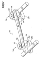
- Figure 1 is a perspective view of a rod to rod connector in accordance with the present invention.
- Figures 2A and 2B are perspective views from two different perspectives of the lower clamping body of a clamping body pair of Figure 1.
- Figure 3 is a perspective view of the upper clamping body of a clamping body pair of Figure 1.
- Figure 4 is a perspective view of the lower and upper clamping bodies forming a clamping body pair in accordance with the present invention joined together prior to insertion of a screw.
- Figure 5 is a plan view of a screw for use in connection with the clamping body pair in accordance with the present invention.
- Figure 6 is a perspective view of a clamping body pair in accordance with the present invention joined together by the screw.
- Figure 7 is a plan view of a rod to rod connector in accordance with the present invention being used to interconnect two spinal rods that are not parallel to each other.
- Figure 8 is a perspective view of a lower clamping member in accordance with an alternative embodiment of the present invention.
- Figures 9A and 9B are perspective views of a rod to rod connector in accordance with another alternative embodiment of the present invention.
- Figure 10 is a perspective view of a rod to rod connector in accordance with another alternative embodiment of the present invention.
- Figure 11 is a perspective view of another rod to rod connector in accordance with yet another alternative embodiment of the present invention.
- Figure 12A is a perspective view of another rod to rod connector in accordance with yet another alternative embodiment of the present invention in which the lower clamping element is shown in cross section.
- Figure 12B is another perspective view of the rod to rod connector of Figure 12 A.
- FIG. 1 is a perspective view of a rod to rod connector 10 in accordance with the present invention interconnecting two generally parallel spinal rods 12.
- the connector 10 comprises a transverse rod 14 and a pair of clamping assemblies 16.
- Each clamping assembly 16 comprises an upper clamping member 18 and a lower clamping member 20.
- Preferably, to two upper clamping members 18 are identical to each other and the two lower clamping members 20 are identical to each other.
- Each clamping assembly 16 further comprises a screw 22.
- the clamping members 18 and 20 preferably are made of a biocompatible, resilient material such as titanium, stainless steel, or any number of biocompatible polymers.
- FIGS 2A and 2B are upper and lower perspective views of a lower clamping member 20. It comprises a C-shaped spinal rod receiving channel 25 sized to accept a spinal rod 12.
- a slot 26 that runs the full depth of the clamping member 20 from the front side walls 28 to the rear sidewall 30 is in communication with the C-shaped channel.
- the slot 26 also runs from the C-shaped channel 25 almost to the rear wall 32 of the clamping body. However, it stops short of the rear wall 32 leaving a portion of material that essentially comprises a hinge 34 around which the slot 26 and the C-shaped channel 25 can be caused to open and close slightly.
- the opening of the C-shaped channel 25 is slightly smaller than the diameter of the spinal rod 12 such that the spinal rod needs to be forced into the channel in a snapping-type action.
- the hinge 34 will spread slightly under the force of pushing the rod into the channel 25, thus allowing the opening to the channel to spread slightly and permit the rod to be inserted into the channel. Once the largest cross-section of the rod passes the opening, the opening will snap shut again to its rest spacing.
- the clamping member 20 further comprises a screw hole 35 that orthogonally intersects the slot 26.
- the screw hole 35 is threaded only in the portion that lies below the slot 26.
- a cylindrical collar 36 comprising a plurality of resilient flanges 36a separated from each other by slots 36b.
- the collar 36 includes a circumferential groove 38.
- the upper ends of flanges define an angled or chamfered surface that can mate with a chamfered surface at the bottom of the head of a screw.
- Figure 3 is a perspective view of one of the upper clamps 18. It also comprises a C-shaped channel 44 accepting the transverse rod 14. In a preferred embodiment, the opening at the top of the C-shaped channel is slightly smaller than the diameter of the transverse rod. Hence, the rod would need to be snapped into the channel.
- the upper clamping member 18 also includes a screw hole 42 extending transversely to the C-shaped rod channel 44. Preferably, the screw hole 42 is not threaded. Furthermore, it is countersunk at its top end as shown at 48.
- the screw hole 42 is orthogonal to the C-shaped channel and is positioned so that a relatively small angular section 49 of that hole 42 intersects the C-shaped channel 44. This leaves a gap in an angular region of the upper portion the screw hole 42.
- a circumferential bead 46 is positioned in the screw hole.
- the bead 46 is positioned so as to mate with the groove 38 when the upper clamp 18 and a lower claim 20 are assembled together.
- the collar 36 of the lower clamping body 20 is longitudinally inserted into the hole 42 of the upper clamping body as shown in Figure 4.
- the diameter of the hole 42 in the upper clamping body 18 is sized to accommodate the collar 36 generally without significant resistance.
- the smallest diameter defined by the bead 46 is slightly smaller than the outer diameter of the collar 36.
- FIG. 5 shows the screw 50 that can be inserted into the coaxial screw holes of the two clamping members 18, 20 in order to fix them to each other.
- the screw 50 comprises a head portion 52 having a chamfered lower surfaces 54 and a threaded shank portion 56.
- the upper portion of the shank 58 that would sit inside the collar portion 36 of the lower clamping member 20 is not threaded.
- Figure 6 is another perspective view of the upper clamp 18 and the lower clamp 20 assembled together, but this time with the screw 50 threaded into the screw holes.
- the screw 50 When the screw 50 is inserted into the clamping members through the top of the collar 36, the threads of its threaded portion 56 will engage with the mating threads of screw hole 35 in the lower clamping member.
- the chamfered bottom 54 of the head 52 of the screw will hit the chamfered inner surface of the tops of the flanges 36a and spread the flanges outwardly. This will cause two things to happen.
- the outer surfaces of the flanges 36a will bear against the chamfered inner surface of the screw hole in the upper clamping member 18, thus locking the two clamping members 18, 20 together in their given relative angular orientation.
- the one or more flanges 36a that are adjacent the cutout portion 49 of the screw hole 42 of the upper clamping member 18 will bear against the rod 14 that is sitting in the C-shaped channel locking it in place in the C-shaped channel.
- the flanges are particularly effective in locking the various components together because the sharp edges of the flanges dig into the inner wall of the screw hole 42 in the upper clamp 18 and into the transverse rod 14.
- Figure 7 is a plain view showing the rod to rod connector 10 of the present invention being used to interconnect to spinal rods that are not perfectly parallel to each other.
- the rod to rod connector 10 of the present invention is very simple to operate, requiring the tightening of only two screws to completely assemble the apparatus as well as couple it to the spinal rods.
- it is a very simple structure comprising a total of seven components, namely, two lower clamps 20, two upper clamps 18, two screws 50 and the transverse rod 14.
- it permits infinite angular positioning of the transverse rod 14 relative to either of the two spinal rods 12.
- Even further, it provides extremely tight clamping of all of the rods to the clamping bodies as well as the angular orientation of the upper and lower clamping bodies to each other.
- the flanges 36a' of the collar 36' of the lower clamping member 20' may have a curvilinear outer surface so as to be shaped to have even greater surface contact with the transverse rod positioned in the C-shaped rod receiving channel 44 of the upper clamp.
- an angular portion 91 of the outer surface of the collar 36", for instance, one of the flanges 36a", of the lower clamping member 90 may be flattened in order to permit the transverse rod 14 to be dropped into the C-shaped transverse rod channel 44 of the upper clamping member without resistance, i.e., without the need to flex one or more of the flanges in order to insert the rod.
- this flattened portion is parallel to the C-shaped spinal rod receiving channel of the lower clamping member.
- the transverse rod 14 can be dropped into the C-shaped transverse rod channel 44 of the upper clamping member 18 when the upper clamping member is oriented relative to the lower clamping member so that the C-shaped channel of the upper clamping member is parallel to the C-shaped channel of the lower clamping member, as shown in Figure 9A.
- the upper clamping member can be rotated relative to the lower clamping member to a position where the two C-shaped channels are approximately orthogonal to each other (i.e., the general position in which almost all of the rods ride connectors will ultimately be deployed in situ) as shown in Figure 9B.
- the transverse rod can be easily placed in the upper clamping member 18 but will essentially immediately be rotated to a position in which it is captured in the clamping assembly 16 and cannot fall out, but is still longitudinally slidable and rotatable in the C-shaped channel of the upper clamping member. This feature is helpful for placing the assemblies on the transverse rod and then placing the rod to rod connector onto the spinal rods.
- one of the upper clamps 18' includes an integral post 66.
- the other upper clamp 18" integrally comprises a tubular hollow shaft 68 for slidingly accepting the post 66 at various distances of insertion.
- a mechanism such as a screw 69 and associated screw hole, are provided to lock the post 66 in the shaft 68 at a selected distance.
- the tubular shaft 68 may be split such that tightening the screw 69 in the screw hole squeezes the shaft 68 to a smaller diameter thus grasping the post 66.
- the screw may be positioned in a threaded hole in the shaft so that the distal end of the screw, when tightened, will bear directly on the post, thus locking the shaft and the post together at the selected distance.
- Other means for fixing the distance between the two pairs of clamping assemblies are well known in the prior art.
- the upper and lower clamps are identical to each other and take the form of the lower clamp described above in connection with Figures 1-3, except that one or both of the clamps do not include the collar 36.
- a rod to rod connector in accordance with this embodiment is shown in Figure 11.
- neither clamping member includes a collar, although one of them could.
- both clamping members lock their respective rods in place by action of the screw 50 closing the hinge so as to squeeze the slots and channels together.
- Figures 12A and 12B are two different perspective views of a rod to rod connector in accordance with yet one more embodiment of the present invention.
- the lower clamping member is shown in partial cutaway.
- the upper clamping element 16 can be the same as in the embodiment of Figure 1.
- the lower clamping member 70 comprises body 71, a channel 72 for accepting the spinal rod 12, a collar 73 essentially identical to the collar 36 previously described, a hole 74, a lever member 76 rotatably mounted to the body 72 via a pivot pin 75.
- the hole 74 is threaded near the top of the hole and is not threaded near the bottom of the hole.
- the pivot pin 75, screw hole 72, and spinal rod channel 72 are all mutually orthogonal to each other.
- the lever member 76 has a first end 78 that is a bearing surface that forms part of the channel 72 for the spinal rod 12.
- the bearing surface is cylindrical and of a diameter equal to that of the spinal rod 12.
- the other end of the lever member 76 is another bearing surface 84 that is positioned in the way of the screw 22 so that, when the screw 22 is tightened, it bears down on the bearings surface 84 of the wedge member forcing the wedge member 76 to rotate about the pivot pin 75, thus causing the other end 80 to fixedly clamp the spinal rod 12.
Landscapes
- Health & Medical Sciences (AREA)
- Orthopedic Medicine & Surgery (AREA)
- Surgery (AREA)
- Life Sciences & Earth Sciences (AREA)
- Neurology (AREA)
- Medical Informatics (AREA)
- Biomedical Technology (AREA)
- Heart & Thoracic Surgery (AREA)
- Engineering & Computer Science (AREA)
- Molecular Biology (AREA)
- Animal Behavior & Ethology (AREA)
- General Health & Medical Sciences (AREA)
- Public Health (AREA)
- Veterinary Medicine (AREA)
- Nuclear Medicine, Radiotherapy & Molecular Imaging (AREA)
- Surgical Instruments (AREA)
- Cable Accessories (AREA)
Abstract
Description
- The invention generally relates to orthopedic devices. More specifically, the present invention is a surgical tool or medical construct used with spinal rods for the purpose of spinal fixation and correction of spinal curvature.
- Spinal rods are often used for spinal fixation, including for correction of scoliotic curves. Fixation using such rods often involves implantation of rods and attaching them to the spine by anchors in the form of hooks and/or screws. Usually, a pair of rods are placed on opposite sides of the portion of the spine to be fixed.
- Various systems have been developed for cross linking spinal rods to prevent rod migration and to increase stiffness of the paired rod assembly.
- Many assemblies used for interconnecting spinal rods, commonly referred to as transverse connector assemblies or rod to rod connectors, utilize a plate mechanism having openings therethrough for adjustably retaining hook systems that are bolted in place in the plate. Examples of such systems include
U.S. Pat. No. 5,334,203 to Wagner andU.S. Pat. No. 5,522,816 to Dinello et al. U.S. Pat. No. 5,498,263 to Dinello et al. , for instance, discloses a transverse connector system utilizing set screws to interconnect vertebrae coupling members while also using plate members as described above for interconnecting the coupling members. A square unit is formed having two sides defined by the plate members and two sides defined by the spaced rods. -
U.S. Pat. No. 5,312,405 to Korotko et al. discloses a coupler used for interconnecting spinal rods wherein the coupler itself is a two piece unit. The neck portion of each unit is interconnected by a screw mechanism which clamps a male portion within a female portion of the system. The system also utilizes coupler inserts or yokes which engage a rod and are compressed about the rod when disposed within a seat portion of each coupler and compressed by an instrument which engages the bottom of the rod between the rod and the spine and the top of the coupler. - In further attempts to overcome these problems, various patents have disclosed devices wherein the set screw directly contacts the rod. Examples of such patents include
U.S. Pat. No. 6,113,600 to Drummond et al. ,U.S. Pat. No. 5,624,442 to Mellinger et al. , andU.S. Pat. No. 5,601,552 to Cotrel . In these patents, the force required to lock the set screw causes deformation of the rod at the point of contact of the set screw. This is more severe in cases where the set screw tip is conically shaped such as that found in FIG. 6 of the Drummond et al. patent. This causes deeper, more localized deformation and therefore stress inducing indentation that can lower rod fatigue life. Additionally, the depth of the notch, as well as the induced localized stress is subject to random values based on how tight the surgeon tightens the set screw at the time of surgery. - Numerous spinal rod systems have also been developed which provide transverse connectors for linking the adjacent spinal rods across the spinal midline to provide a rigid and stable construct. Most of these systems present one or more difficulties for spinal surgeons. Many of the devices are high profile, which increases soft tissue trauma and surgical complications. Furthermore, in many of these prior art systems, the attachment devices must be preloaded on the spinal rods, which can require significant pre-operative planning and which virtually eliminates the opportunity to add connectors in situ.
- One transverse connector system is the TSRH™ CROSSLINK™ of Danek Medical, Inc. The TSRH™ CROSSLINK™ utilizes a three point shear clamp mechanism which restricts motion between the rods in all directions, and particularly resists axial forces between rods and torsional moments about the axis of the rods. A quadrilateral construct is formed by laterally connecting the rods across the sagittal plane with rigid plates. The lateral connection reduces the loss of correction that can occur over time.
- Rigid transverse connections between spinal rods are beneficial because they restrict rod migration and increase construct stiffness. In many cases involving multi-level fusion of the spine, these features are highly beneficial while stabilizing the spine construct until fusion in accomplished while solid bone fusion is accomplished. In the post-operative period before fusion occurs, a significant amount of motion can occur between the rods, wires and hooks, which can, for example, allow a scoliotic correlation to decrease or the pelvis to de-rotate toward its previous, deformed position. By providing a rigid transverse connection between two spinal rods, the loss of correction can be reduced and a stiffer construct can be created which may enhance the promotion of a solid fusion. While other devices may provide a good construct, a need has remained for low profile devices where the surface area of contact with the rod is greatly increased and thus minimizes localized stress regardless of how tight the set screw is secured.
- It is sometimes the case that the two side by side spinal rods that are to be interconnected by a rod to rod connector are not perfectly parallel to each other. This is a problem for many rod to rod connectors of the prior art which do not permit for any angle between the two spinal rods.
- It is an object of the present invention to provide a rod to rod connector that engages a rod by a simple locking mechanism.
- It is another object of the present invention to provide a rod to rod connector having few parts and requiring minimal manipulation to assemble and provide the interconnection.
- It is a further object of the present invention to provide a rod to rod connector that requires only a simple screw driver or nut driver outside of the assembly for its interconnection between a pair of spinal rods.
- It is yet another object of the present invention to develop a rod to rod connector having a surface area of contact with the rod that is greatly increased and thus minimizes localized stress regardless of how tight the set screw is set.
- Even further, it is an object of the present invention to provide a rod to rod connector that permits for different angles between two side-by-side spinal rods.
- The invention is a rod to rod connector that, for instance, can be used to interconnect two generally parallel spinal rods of a spinal rod and anchor system. The rod to rod connector comprises a transverse rod and two pairs of clamping bodies, one for each spinal rod. Each pair of clamping bodies connects one of the longitudinal spinal rods to the transverse rod in an infinitely adjustable angular relationship to each other. One of the two clamping bodies of each pair comprises a C-shaped channel for accepting the spinal rod. The channel is in communication with a slot that defines a hinge. A threaded screw hole passes transversely through the slot and permits a screw to squeeze the hinge, thereby narrowing the slot and causing the C-shaped channel to close around and clamp the spinal rod. The second clamping body of each pair is similar to the first except that there is no slot or hinge, and the screw hole preferably is not threaded, but instead includes a countersink for seating a chamfered screw head. Also, an angular portion of the screw hole intersects the C-shaped channel, which accepts the transverse rod.
- The two clamping bodies are aligned with each other so that their screw holes are coaxial with each other and a single screw clamps both rods in the C-shaped channels and fixes the angular relationship between the two clamping bodies. The first clamp clamps the spinal rod by squeezing the hinge and slot so as to cause the C-shaped spinal rod channel to squeeze around the rod. The second clamp clamps the transverse rod by virtue of the bottom surface of the screw head bearing down on the rod over the portion of the screw hole that intersects the C-shaped transverse rod channel.
- In a preferred embodiment, the first clamp of each pair further comprises a plurality of flanges defining a collar that extends coaxially from the screw hole, which flanges fit within the screw hole of the second clamping body when the two clamping bodies are aligned and joined. The flanges spread outwardly when forced downwardly by a screw head having a chamfered bottom causing the flanges to dig into the interior surface of the screw hole of the other clamping body. This feature provides extra gripping between the two clamping bodies thus providing even greater resistance to any unintentional change in the angle between the spinal rod and the transverse rod once the screw is tightened.
- Figure 1 is a perspective view of a rod to rod connector in accordance with the present invention.
- Figures 2A and 2B are perspective views from two different perspectives of the lower clamping body of a clamping body pair of Figure 1.
- Figure 3 is a perspective view of the upper clamping body of a clamping body pair of Figure 1.
- Figure 4 is a perspective view of the lower and upper clamping bodies forming a clamping body pair in accordance with the present invention joined together prior to insertion of a screw.
- Figure 5 is a plan view of a screw for use in connection with the clamping body pair in accordance with the present invention.
- Figure 6 is a perspective view of a clamping body pair in accordance with the present invention joined together by the screw.
- Figure 7 is a plan view of a rod to rod connector in accordance with the present invention being used to interconnect two spinal rods that are not parallel to each other.
- Figure 8 is a perspective view of a lower clamping member in accordance with an alternative embodiment of the present invention.
- Figures 9A and 9B are perspective views of a rod to rod connector in accordance with another alternative embodiment of the present invention.
- Figure 10 is a perspective view of a rod to rod connector in accordance with another alternative embodiment of the present invention.
- Figure 11 is a perspective view of another rod to rod connector in accordance with yet another alternative embodiment of the present invention.
- Figure 12A is a perspective view of another rod to rod connector in accordance with yet another alternative embodiment of the present invention in which the lower clamping element is shown in cross section.
- Figure 12B is another perspective view of the rod to rod connector of Figure 12 A.
- Figure 1 is a perspective view of a rod to
rod connector 10 in accordance with the present invention interconnecting two generally parallelspinal rods 12. Theconnector 10 comprises atransverse rod 14 and a pair of clampingassemblies 16. Each clampingassembly 16 comprises anupper clamping member 18 and alower clamping member 20. Preferably, to twoupper clamping members 18 are identical to each other and the twolower clamping members 20 are identical to each other. Each clampingassembly 16 further comprises ascrew 22. The clampingmembers - Figures 2A and 2B are upper and lower perspective views of a
lower clamping member 20. It comprises a C-shaped spinalrod receiving channel 25 sized to accept aspinal rod 12. Aslot 26 that runs the full depth of the clampingmember 20 from thefront side walls 28 to therear sidewall 30 is in communication with the C-shaped channel. Theslot 26 also runs from the C-shapedchannel 25 almost to therear wall 32 of the clamping body. However, it stops short of therear wall 32 leaving a portion of material that essentially comprises ahinge 34 around which theslot 26 and the C-shapedchannel 25 can be caused to open and close slightly. - In a preferred embodiment of the invention, the opening of the C-shaped
channel 25 is slightly smaller than the diameter of thespinal rod 12 such that the spinal rod needs to be forced into the channel in a snapping-type action. Particularly, thehinge 34 will spread slightly under the force of pushing the rod into thechannel 25, thus allowing the opening to the channel to spread slightly and permit the rod to be inserted into the channel. Once the largest cross-section of the rod passes the opening, the opening will snap shut again to its rest spacing. By making the opening slightly smaller than the diameter of the rod, when snapped in, the rod is loosely secured in the channel so that it cannot inadvertently fall out through the opening, but can be rotated and/or slid longitudinally in thechannel 25. This permits full adjustability of the spacing between the clamping member pairs 16 and permits thetransverse rod 14 to be rotated while minimizing the likelihood of therod 14 inadvertently coming out of the clampingbodies 18. - The clamping
member 20 further comprises ascrew hole 35 that orthogonally intersects theslot 26. Thescrew hole 35 is threaded only in the portion that lies below theslot 26. - Extending outwardly from the clamping
member 20 and coaxial with thescrew hole 35 is acylindrical collar 36 comprising a plurality ofresilient flanges 36a separated from each other byslots 36b. Preferably, thecollar 36 includes acircumferential groove 38. Also preferably, the upper ends of flanges define an angled or chamfered surface that can mate with a chamfered surface at the bottom of the head of a screw. - Figure 3 is a perspective view of one of the
upper clamps 18. It also comprises a C-shapedchannel 44 accepting thetransverse rod 14. In a preferred embodiment, the opening at the top of the C-shaped channel is slightly smaller than the diameter of the transverse rod. Hence, the rod would need to be snapped into the channel. Theupper clamping member 18 also includes ascrew hole 42 extending transversely to the C-shapedrod channel 44. Preferably, thescrew hole 42 is not threaded. Furthermore, it is countersunk at its top end as shown at 48. Thescrew hole 42 is orthogonal to the C-shaped channel and is positioned so that a relatively smallangular section 49 of thathole 42 intersects the C-shapedchannel 44. This leaves a gap in an angular region of the upper portion thescrew hole 42. - Even further, a
circumferential bead 46 is positioned in the screw hole. Thebead 46 is positioned so as to mate with thegroove 38 when theupper clamp 18 and alower claim 20 are assembled together. Specifically, in order to assemble the two clampingbodies collar 36 of thelower clamping body 20 is longitudinally inserted into thehole 42 of the upper clamping body as shown in Figure 4. The diameter of thehole 42 in theupper clamping body 18 is sized to accommodate thecollar 36 generally without significant resistance. However, the smallest diameter defined by thebead 46 is slightly smaller than the outer diameter of thecollar 36. Therefore, as thecollar 36 is inserted into thehole 42, theflanges 36a are flexed slightly inwardly until thebead 46 meets thegroove 38, at which point theflanges 36a can snap outward thus mating thebead 46 and thegroove 38. This design loosely joins theupper clamp 18 andlower clamp 20 and prevents them from inadvertently becoming unassembled from each other, yet permits the two clamping members to be rotated relative to each other about the longitudinal axis of their coaxial screw holes. - Figure 5 shows the
screw 50 that can be inserted into the coaxial screw holes of the two clampingmembers screw 50 comprises ahead portion 52 having a chamferedlower surfaces 54 and a threadedshank portion 56. Preferably, the upper portion of theshank 58 that would sit inside thecollar portion 36 of thelower clamping member 20 is not threaded. - Figure 6 is another perspective view of the
upper clamp 18 and thelower clamp 20 assembled together, but this time with thescrew 50 threaded into the screw holes. When thescrew 50 is inserted into the clamping members through the top of thecollar 36, the threads of its threadedportion 56 will engage with the mating threads ofscrew hole 35 in the lower clamping member. As thescrew 50 is rotated to advance it into thelower clamping member 20, the chamferedbottom 54 of thehead 52 of the screw will hit the chamfered inner surface of the tops of theflanges 36a and spread the flanges outwardly. This will cause two things to happen. First, the outer surfaces of theflanges 36a will bear against the chamfered inner surface of the screw hole in the upper clampingmember 18, thus locking the two clampingmembers more flanges 36a that are adjacent thecutout portion 49 of thescrew hole 42 of the upper clampingmember 18 will bear against therod 14 that is sitting in the C-shaped channel locking it in place in the C-shaped channel. The flanges are particularly effective in locking the various components together because the sharp edges of the flanges dig into the inner wall of thescrew hole 42 in theupper clamp 18 and into thetransverse rod 14. - Simultaneously as the
screw 50 is tightened, it squeezes closed theslot 26 and C-shapedchannel 25 in thelower clamping member 20, thus clamping thespinal rod 12 securely in thelower clamping member 20. Thus, by the tightening of a single screw, both rods are caused to be locked in the clamping assembly and the angular orientations of the two rods also is fixed. - Figure 7 is a plain view showing the rod to
rod connector 10 of the present invention being used to interconnect to spinal rods that are not perfectly parallel to each other. It should be clear from the foregoing description that the rod torod connector 10 of the present invention is very simple to operate, requiring the tightening of only two screws to completely assemble the apparatus as well as couple it to the spinal rods. Furthermore, it is a very simple structure comprising a total of seven components, namely, twolower clamps 20, twoupper clamps 18, twoscrews 50 and thetransverse rod 14. Also, it permits infinite angular positioning of thetransverse rod 14 relative to either of the twospinal rods 12. Even further, it provides extremely tight clamping of all of the rods to the clamping bodies as well as the angular orientation of the upper and lower clamping bodies to each other. - Various modifications of the design are contemplated. For instance, in a first alternative embodiment shown in Figure 8, the
flanges 36a' of the collar 36' of the lower clamping member 20' may have a curvilinear outer surface so as to be shaped to have even greater surface contact with the transverse rod positioned in the C-shapedrod receiving channel 44 of the upper clamp. - In another alternative embodiment shown in Figures 9A and 9B, an angular portion 91 of the outer surface of the
collar 36", for instance, one of theflanges 36a", of the lower clamping member 90 may be flattened in order to permit thetransverse rod 14 to be dropped into the C-shapedtransverse rod channel 44 of the upper clamping member without resistance, i.e., without the need to flex one or more of the flanges in order to insert the rod. Preferably, this flattened portion is parallel to the C-shaped spinal rod receiving channel of the lower clamping member. Thus, thetransverse rod 14 can be dropped into the C-shapedtransverse rod channel 44 of the upper clampingmember 18 when the upper clamping member is oriented relative to the lower clamping member so that the C-shaped channel of the upper clamping member is parallel to the C-shaped channel of the lower clamping member, as shown in Figure 9A. Then, the upper clamping member can be rotated relative to the lower clamping member to a position where the two C-shaped channels are approximately orthogonal to each other (i.e., the general position in which almost all of the rods ride connectors will ultimately be deployed in situ) as shown in Figure 9B. In this manner, the transverse rod can be easily placed in the upper clampingmember 18 but will essentially immediately be rotated to a position in which it is captured in the clampingassembly 16 and cannot fall out, but is still longitudinally slidable and rotatable in the C-shaped channel of the upper clamping member. This feature is helpful for placing the assemblies on the transverse rod and then placing the rod to rod connector onto the spinal rods. - In yet another embodiment of the present invention shown in Figure 10, the need for separate
transverse rod 14 is eliminated by means of modifiedupper clamping members 18' and 18". As shown in Figure 10, one of the upper clamps 18' includes anintegral post 66. The otherupper clamp 18" integrally comprises a tubularhollow shaft 68 for slidingly accepting thepost 66 at various distances of insertion. A mechanism, such as ascrew 69 and associated screw hole, are provided to lock thepost 66 in theshaft 68 at a selected distance. Thetubular shaft 68 may be split such that tightening thescrew 69 in the screw hole squeezes theshaft 68 to a smaller diameter thus grasping thepost 66. Alternatively, the screw may be positioned in a threaded hole in the shaft so that the distal end of the screw, when tightened, will bear directly on the post, thus locking the shaft and the post together at the selected distance. Other means for fixing the distance between the two pairs of clamping assemblies are well known in the prior art. - In another variation of the present invention, the upper and lower clamps are identical to each other and take the form of the lower clamp described above in connection with Figures 1-3, except that one or both of the clamps do not include the
collar 36. A rod to rod connector in accordance with this embodiment is shown in Figure 11. In this particular embodiment, neither clamping member includes a collar, although one of them could. In this embodiment, both clamping members lock their respective rods in place by action of thescrew 50 closing the hinge so as to squeeze the slots and channels together. - Figures 12A and 12B are two different perspective views of a rod to rod connector in accordance with yet one more embodiment of the present invention. In Figure 12A, the lower clamping member is shown in partial cutaway.
- The
upper clamping element 16 can be the same as in the embodiment of Figure 1. In this embodiment, thelower clamping member 70 comprisesbody 71, achannel 72 for accepting thespinal rod 12, acollar 73 essentially identical to thecollar 36 previously described, ahole 74, alever member 76 rotatably mounted to thebody 72 via apivot pin 75. Unlike the first embodiment disclosed hereinabove, in this embodiment, thehole 74 is threaded near the top of the hole and is not threaded near the bottom of the hole. Thepivot pin 75,screw hole 72, andspinal rod channel 72 are all mutually orthogonal to each other. - The
lever member 76 has afirst end 78 that is a bearing surface that forms part of thechannel 72 for thespinal rod 12. Preferably, the bearing surface is cylindrical and of a diameter equal to that of thespinal rod 12. The other end of thelever member 76 is another bearingsurface 84 that is positioned in the way of thescrew 22 so that, when thescrew 22 is tightened, it bears down on the bearings surface 84 of the wedge member forcing thewedge member 76 to rotate about thepivot pin 75, thus causing the other end 80 to fixedly clamp thespinal rod 12. - Having thus described a few particular embodiments of the invention, various alterations, modifications, and improvements will readily occur to those skilled in the art. Such alterations, modifications and improvements as are made obvious by this disclosure are intended to be part of this description though not expressly stated herein, and are intended to be within the spirit and scope of the invention. Accordingly, the foregoing description is by way of example only, and not limiting. The invention is limited only as defined in the following claims and equivalents thereto.
Claims (40)
- A transverse connector for rigidly connecting first and second spinal rods to each other comprising:a transverse connecting member;a first clamping assembly for rigidly attaching said transverse connecting member to a first spinal rod, said first clamping assembly comprising:a first clamping body including a channel for receiving said first spinal rod;a second clamping body including a channel for receiving said transverse connecting member and a hole transverse to said channel; anda collar extending from said first clamping body into said hole of said second clamping body, said collar comprising a plurality of resilient flanges; anda second clamping assembly for rigidly attaching said transverse connecting member to a second spinal rod.
- The transverse connector of claim 1 wherein said collar comprises one of a circumferential bead and groove and said hole of said second clamping body comprises the other of said circumferential bead and groove, wherein said groove and bead are positioned and sized to mate with each other when said first and second clamping bodies are assembled together with said collar extending into said hole whereby said first and second clamping bodies are rotatably coupled together.
- The transverse connector of claim 2 wherein said collar and said hole of said second clamping body are sized and shaped so that said resilient flanges are deflected inwardly when they meet the bead, but snap back out when said bead meets said groove.
- The transverse connector of claim 1 wherein said collar is sized relative to said second clamping body such that at least a first circumferential portion of said collar interferes with the insertion of a rod in said channel of said second clamping body whereby said collar must be deflected inwardly in order to allow a rod to enter said channel when said first and second clamping bodies are assembled.
- The transverse connector of claim 4 wherein at least a second circumferential angular portion of said collar has a flattened outer surface such that a rod can be inserted into said channel without interference from said collar when said first and second clamping bodies are assembled and aligned such that said flattened circumferential portion of said collar of said first clamping body is adjacent said portion of said screw hole of said second clamping body that intersects said screw hole of said second clamping body.
- The transverse connector of claim 5 wherein said flattened portion comprises one of said flanges.
- The transverse connector of claim 5 wherein said flattened portion is positioned on said collar such that it is adjacent said portion of said screw hole of said second clamping body that intersects said screw hole of said second clamping body when said channel of said first clamping body and said channel of said second clamping body are parallel to each other.
- The transverse connector of claim 1 wherein said first clamping body further comprises a screw hole coaxial with and through said collar, said screw hole being at least partially threaded and further comprising a screw extending through said screw hole of said first clamping body and said hole of said second clamping body for connecting said first and second clamping bodies together.
- The transverse connector of claim 8 wherein said screw comprises a head and a threaded shank and wherein a portion of said screw hole of said second clamping body intersects said channel of said second clamping body such that said head of said screw will bear against a transverse connecting member disposed in said channel of said second clamping body thereby rigidly fixing said transverse connecting member in said channel.
- The transverse connector of claim 9 wherein said channel for receiving said spinal rod further comprises a hinge whereby said channel can be reduced in size around said spinal rod when said screw is tightened into said screw hole in said first clamping body.
- The transverse connector of claim 10 wherein said channel of said first clamping body comprises a C-shaped channel for accepting said spinal rod, and a slot intersecting said C-shaped channel at one end, said hinge being formed of material of said first clamping body at a second end of said slot.
- The transverse connector of claim 11 wherein said screw hole of said first clamping body intersects said slot perpendicularly to said slot and comprises threads only below said slot.
- A transverse connector for rigidly connecting first and second spinal rods to each other comprising:a transverse connecting member;a first clamping assembly for rigidly attaching said transverse connecting member to a first spinal rod, said clamping assembly comprising:a first clamping body including a hinged channel for receiving said first spinal rod, and a screw hole transverse to said hinged channel, said screw hole being at least partially threaded;a second clamping body including a channel for receiving said transverse connecting member and a screw hole transverse to said channel, said screw hole being coaxially arranged with said screw hole of said first clamping body; anda screw extending through said screw holes of said first and second clamping bodies for connecting said first and second clamping bodies together and squeezing said hinge so as to cause said hinged channel to close around and clamp a rod disposed in said channel of said first clamping body; anda second clamping assembly for rigidly attaching said transverse connecting member to a second spinal rod.
- The transverse connector of claim 13 wherein said transverse connecting member comprises a rod.
- The transverse connector of claim 14 wherein said screw comprises a head and a threaded shank and wherein a portion of said screw hole of said second clamping body intersects said channel of said second clamping body such that said head of said screw will bear against a transverse connecting member disposed in said channel of said second clamping body thereby rigidly fixing said transverse connecting member in said channel.
- The transverse connector of claim 15 wherein said hinged channel of said first clamping body comprises a C-shaped channel for accepting said spinal rod, and a slot intersecting said C-shaped channel at one end and defining a hinge formed of material of said first clamping body at a second end thereof.
- The transverse connector of claims 16 wherein said slot runs a full depth of said first clamping body from a front surface to a rear surface of said clamping body in the direction of said channel.
- The transverse connector of claim 17 wherein said screw hole of said first clamping body intersects said slot perpendicularly to said slot and comprises threads only below said slot.
- The transverse connector of claim 13 wherein said first clamping body further comprises a collar extending from said clamping body coaxially with said screw hole of said first clamping body, said collar comprising a plurality of resilient flanges adapted to fit within said screw hole of said second clamping body.
- The transverse connector of claim 19 wherein said collar comprises one of a circumferential bead and groove and said screw hole of said second clamping body comprises the other of said circumferential bead and groove, wherein said groove and bead are positioned and sized to mate with each other when said first and second clamping bodies are assembled together to rotatably couple said first and second clamping bodies together.
- The transverse connector of claim 20 wherein said collar and said screw hole of said second clamping body are sized and shaped so that said resilient flanges are deflected inwardly when they meet the bead, but snap back out when said bead meets said groove.
- The transverse connector of claim 19 wherein said collar is sized relative to said second clamping body such that at least a circumferential portion of said collar interferes with the insertion of a rod in said channel of said second clamping body whereby said collar must be deflected inwardly in order to allow a rod to enter said channel when said first and second clamping bodies are assembled.
- The transverse connector of claim 22 wherein at least another circumferential angular portion of said collar has a flattened outer surface such that a rod can be inserted into said channel without interference from said collar when said first and second clamping bodies are assembled and aligned such that said flattened circumferential portion of said collar of said first clamping body is adjacent said portion of said screw hole of said second clamping body that intersects said screw hole of said second clamping body.
- The transverse connector of claim 23 wherein said flattened portion comprises one of said flanges.
- The transverse connector of claim 23 wherein said flattened portion is positioned on said collar such that it is adjacent said portion of said screw hole of said second clamping body that intersects said screw hole of said second clamping body when said channel of said first clamping body and said channel of said second clamping body are parallel to each other.
- The transverse connector of claim 19 wherein said screw head bears against said transverse connecting member through said collar.
- The transverse connector of claim 13 wherein said second clamping assembly comprises:a third clamping body including a hinged channel for receiving said second spinal rod, and a screw hole transverse to said hinged channel, said screw hole being at least partially threaded;a fourth clamping body including a channel for receiving said transverse connecting member and a screw hole transverse to said channel, said screw hole being coaxially arranged with said screw hole of said first clamping body; anda second screw extending through said screw holes of said third and fourth clamping bodies for connecting said third and fourth clamping bodies together and squeezing said hinge so as to cause said hinged channel to close around and clamp a rod disposed in said channel of said third clamping body.
- The transverse connector of claim 27 wherein said second screw comprises a head and a threaded shank and wherein a portion of said second screw hole of said fourth clamping body intersects said channel of said fourth clamping body such that said head of said second screw will bear against a transverse connecting member disposed in said channel of said fourth clamping body thereby rigidly fixing said transverse connecting member in said channel.
- The transverse connector of claim 28 wherein said hinged channel of said third clamping body comprises a C-shaped channel for accepting said second spinal rod, and a slot intersecting said C-shaped channel at one end and defining a hinge formed of material of said third clamping body at a second end thereof.
- The transverse connector of claims 29 wherein said slot runs a full depth of said third clamping body from a front surface to a rear surface of said clamping body in the direction of said channel.
- A transverse connector for rigidly connecting first and second spinal rods to each other comprising:a first clamping assembly for rigidly attaching said transverse connecting member to a first spinal rod, said clamping assembly comprising:a first clamping body including a hinged channel for receiving said first spinal rod, and a screw hole transverse to said hinged channel, said screw hole being at least partially threaded;a second clamping body including a channel for receiving said transverse connecting member and a screw hole transverse to said channel, said screw hole being coaxially arranged with said screw hole of said first clamping body;a screw extending through said screw holes of said first and second clamping bodies for connecting said first and second clamping bodies together and squeezing said hinge so as to cause said hinged channel to close around and clamp a rod disposed in said channel of said first clamping body; andone of a post and a hollow tubular shaft extending from said first clamping body;a second clamping assembly for rigidly attaching said transverse connecting member to a second spinal rod, said second clamping assembly including the other of said post and hollow tubular shaft, said shaft and post adapted to slidingly engage with each other; andmeans for locking said post in said shaft at a selected distance.
- The transverse connector of claim 31 wherein said means for locking comprises a screw hole in said shaft and a screw.
- A transverse connector for rigidly connecting first and second spinal rods to each other comprising:a transverse connecting member;a first clamping assembly for rigidly attaching said transverse connecting member to a first spinal rod, said first clamping assembly comprising:a first clamping body including a channel for receiving said transverse connecting member and a hole transverse to said channel;a screw;a second clamping body including, a hole for accepting said screw, a channel for receiving said first spinal rod, a pivot pin, a lever member coupled to said second clamping body by said pivot pin, said lever member comprising first and second longitudinal ends, said first end positioned to be rotated about said pivot pin by advancement of said screw into said hole, said second end positioned to bear against said rod and clamp said rod in said channel upon said lever member being rotated by said screw; anda second clamping assembly for rigidly attaching said transverse connecting member to a second spinal rod;
wherein said holes in said first and second clamping bodies are coaxial so that said screw can be advanced through said holes to join together said first and second clamping bodies. - The transverse connector of claim 33 wherein said pivot pin, said channel and said hole in said second clamping body are mutually orthogonal to each other.
- The transverse connector of claim 33 wherein said second end of said lever is arcuate having a diameter equal to the diameter of said spinal rod.
- The transverse connector of claim 33 wherein said screw is threaded and said hole in said second clamping body is threaded so as to engage mating threads on said screw.
- The transverse connector of claim 36 wherein said second clamping body further comprises a collar extending from said second clamping body into said hole of said first clamping body, said collar comprising a plurality of resilient flanges.
- The transverse connector of claim 37 wherein said collar comprises one of a circumferential bead and groove and said hole of said second clamping body comprises the other of said circumferential bead and groove, wherein said groove and bead are positioned and sized to mate with each other when said first and second clamping bodies are assembled together with said collar extending into said hole whereby said first and second clamping bodies are rotatably coupled together.
- The transverse connector of claim 38 wherein said collar and said hole of said second clamping body are sized and shaped so that said resilient flanges are deflected inwardly when they meet the bead, but snap back out when said bead meets said groove.
- The transverse connector of claim 39 wherein said screw comprises a head and a threaded shank and wherein a portion of said screw hole of said first clamping body intersects said channel of said first clamping body such that said head of said screw will bear against a transverse connecting member disposed in said channel of said first clamping body thereby rigidly fixing said transverse connecting member in said channel.
Applications Claiming Priority (2)
| Application Number | Priority Date | Filing Date | Title |
|---|---|---|---|
| US71038905P | 2005-08-23 | 2005-08-23 | |
| US11/221,512 US7628799B2 (en) | 2005-08-23 | 2005-09-08 | Rod to rod connector |
Publications (2)
| Publication Number | Publication Date |
|---|---|
| EP1762195A1 true EP1762195A1 (en) | 2007-03-14 |
| EP1762195B1 EP1762195B1 (en) | 2008-05-07 |
Family
ID=37654769
Family Applications (1)
| Application Number | Title | Priority Date | Filing Date |
|---|---|---|---|
| EP06016987A Active EP1762195B1 (en) | 2005-08-23 | 2006-08-16 | Rod to rod connector |
Country Status (5)
| Country | Link |
|---|---|
| US (1) | US7628799B2 (en) |
| EP (1) | EP1762195B1 (en) |
| AT (1) | ATE394074T1 (en) |
| DE (1) | DE602006001088D1 (en) |
| ES (1) | ES2303300T3 (en) |
Cited By (5)
| Publication number | Priority date | Publication date | Assignee | Title |
|---|---|---|---|---|
| WO2010128700A1 (en) * | 2009-05-04 | 2010-11-11 | (주)엘앤케이바이오메드 | Side click connector device for connection of spinal rods |
| EP2496778A1 (en) * | 2009-11-06 | 2012-09-12 | Intelligent Implant Systems | Rod to rod connector with load sharing |
| EP2884924A4 (en) * | 2012-08-15 | 2016-04-13 | Blackstone Medical Inc | Pivoting spinal fixation devices |
| EP3219270A1 (en) * | 2016-03-16 | 2017-09-20 | Globus Medical, Inc. | Transverse connectors for spinal systems |
| EP3563784A1 (en) * | 2018-05-03 | 2019-11-06 | K2M, Inc. | Head to head transverse connector |
Families Citing this family (88)
| Publication number | Priority date | Publication date | Assignee | Title |
|---|---|---|---|---|
| US8034082B2 (en) * | 2004-07-08 | 2011-10-11 | Globus Medical, Inc. | Transverse fixation device for spinal fixation systems |
| US7959653B2 (en) * | 2004-09-03 | 2011-06-14 | Lanx, Inc. | Spinal rod cross connector |
| US20070225713A1 (en) * | 2004-10-20 | 2007-09-27 | Moti Altarac | Systems and methods for posterior dynamic stabilization of the spine |
| WO2006058221A2 (en) | 2004-11-24 | 2006-06-01 | Abdou Samy M | Devices and methods for inter-vertebral orthopedic device placement |
| JP4896138B2 (en) * | 2005-09-30 | 2012-03-14 | アエスキュラップ アーゲー | Occipital cervical spine fixation system |
| ES2436101T3 (en) * | 2005-10-07 | 2013-12-27 | Alphatec Spine, Inc. | Adjustable occipital plate |
| US8100946B2 (en) | 2005-11-21 | 2012-01-24 | Synthes Usa, Llc | Polyaxial bone anchors with increased angulation |
| US7708736B2 (en) * | 2006-02-22 | 2010-05-04 | Extraortho, Inc. | Articulation apparatus for external fixation device |
| US7780704B2 (en) * | 2006-03-10 | 2010-08-24 | Custom Spine, Inc. | Spinal cross-connector |
| US7695500B2 (en) * | 2006-03-10 | 2010-04-13 | Custom Spine, Inc. | Polyaxial occipital plate |
| US7833248B2 (en) * | 2006-03-10 | 2010-11-16 | Custom Spine, Inc. | Spinal cross-connector |
| US8132774B1 (en) * | 2006-04-17 | 2012-03-13 | Douglas Whatcott | Concrete forming screed aids |
| US20080237418A1 (en) * | 2006-09-28 | 2008-10-02 | Rockler Companies, Inc. | Clamp Bench Blocks |
| US8721689B2 (en) * | 2006-10-04 | 2014-05-13 | Life Spine, Inc. | Multi-axial spinal cross-connectors |
| US7744632B2 (en) * | 2006-12-20 | 2010-06-29 | Aesculap Implant Systems, Inc. | Rod to rod connector |
| US7789895B2 (en) * | 2006-12-26 | 2010-09-07 | Warsaw Orthopedic, Inc. | Sacral reconstruction fixation device |
| US8568453B2 (en) * | 2007-01-29 | 2013-10-29 | Samy Abdou | Spinal stabilization systems and methods of use |
| WO2009012186A1 (en) | 2007-07-13 | 2009-01-22 | Life Spine, Inc. | Spinal cross-connector |
| US9439681B2 (en) | 2007-07-20 | 2016-09-13 | DePuy Synthes Products, Inc. | Polyaxial bone fixation element |
| US8048129B2 (en) * | 2007-08-15 | 2011-11-01 | Zimmer Spine, Inc. | MIS crosslink apparatus and methods for spinal implant |
| EP2197372B1 (en) * | 2007-09-27 | 2016-04-13 | Zimmer, Inc. | Clamping apparatus for external fixation and stabilization |
| US8292924B2 (en) * | 2007-10-05 | 2012-10-23 | Spineworks, Llc | Enhanced pedicle rod clamp device |
| WO2009089123A1 (en) * | 2008-01-04 | 2009-07-16 | Life Spine, Inc. | Spinal cross-connector with spinal extensor muscle curvature |
| US8864798B2 (en) * | 2008-01-18 | 2014-10-21 | Globus Medical, Inc. | Transverse connector |
| US9060813B1 (en) | 2008-02-29 | 2015-06-23 | Nuvasive, Inc. | Surgical fixation system and related methods |
| FR2929100B1 (en) * | 2008-03-25 | 2011-04-15 | Medicrea International | VERTEBRAL ARTHRODESIS EQUIPMENT |
| WO2010017471A1 (en) * | 2008-08-07 | 2010-02-11 | The Children's Mercy Hospital | Sliding rod system for correcting spinal deformities |
| US9241739B2 (en) | 2008-09-12 | 2016-01-26 | DePuy Synthes Products, Inc. | Spinal stabilizing and guiding fixation system |
| EP2339975B1 (en) | 2008-09-29 | 2015-03-25 | Synthes GmbH | Polyaxial bottom-loading screw and rod assembly |
| WO2010062736A1 (en) | 2008-11-03 | 2010-06-03 | Synthes Usa, Llc | Uni-planar bone fixation assembly |
| US8998961B1 (en) | 2009-02-26 | 2015-04-07 | Lanx, Inc. | Spinal rod connector and methods |
| WO2010120989A1 (en) * | 2009-04-15 | 2010-10-21 | Synthes Usa, Llc | Revision connector for spinal constructs |
| CA2759249A1 (en) | 2009-04-23 | 2010-10-28 | Spinal Elements, Inc. | Transverse connectors |
| JP5654584B2 (en) * | 2009-06-17 | 2015-01-14 | ジンテス ゲゼルシャフト ミット ベシュレンクテル ハフツング | Correction connector for spine construction |
| US8348981B2 (en) * | 2009-06-23 | 2013-01-08 | Aesculap Implany Systems, LLC | Minimal access occipital plate |
| US8246657B1 (en) | 2009-06-29 | 2012-08-21 | Nuvasive, Inc. | Spinal cross connector |
| US8568456B2 (en) | 2009-09-21 | 2013-10-29 | Globus Medical, Inc. | Transverse connector having a locking element for capturing multiple rods |
| IT1396145B1 (en) * | 2009-11-05 | 2012-11-16 | Citieffe Srl | MULTI-PURPOSE EXTERNAL FIXER. |
| US9078703B2 (en) * | 2009-11-25 | 2015-07-14 | Spine21 Ltd. | Spinal rod having a post-operative adjustable dimension |
| US8764806B2 (en) | 2009-12-07 | 2014-07-01 | Samy Abdou | Devices and methods for minimally invasive spinal stabilization and instrumentation |
| US9198696B1 (en) | 2010-05-27 | 2015-12-01 | Nuvasive, Inc. | Cross-connector and related methods |
| EP2588013B1 (en) | 2010-07-01 | 2016-05-04 | Zimmer, Inc. | Multi-locking external fixation clamp |
| US8920471B2 (en) | 2010-07-12 | 2014-12-30 | K2M, Inc. | Transverse connector |
| US8777996B2 (en) * | 2010-07-12 | 2014-07-15 | Globus Medical, Inc. | Interspinous ligament transverse connector |
| WO2012051255A1 (en) | 2010-10-12 | 2012-04-19 | Extraortho, Inc. | External fixation surgical clamp with swivel |
| US8840611B2 (en) | 2010-10-12 | 2014-09-23 | Zimmer, Inc. | Single lock external fixation clamp arrangement and method |
| US8728078B2 (en) | 2010-11-04 | 2014-05-20 | Zimmer, Inc. | Clamping assembly with links |
| US20120130436A1 (en) | 2010-11-23 | 2012-05-24 | Aesculap Implant Systems, Llc | Head to head connector for bone fixation assemblies |
| EP2648634B1 (en) | 2010-12-09 | 2016-05-18 | Zimmer, Inc. | Revolving lock for external fixation clamps |
| EP2648633B1 (en) | 2010-12-09 | 2016-05-18 | Zimmer, Inc. | External fixation clamp with cam driven jaw |
| US8920475B1 (en) | 2011-01-07 | 2014-12-30 | Lanx, Inc. | Vertebral fixation system including torque mitigation |
| US9387013B1 (en) | 2011-03-01 | 2016-07-12 | Nuvasive, Inc. | Posterior cervical fixation system |
| US9247964B1 (en) | 2011-03-01 | 2016-02-02 | Nuasive, Inc. | Spinal Cross-connector |
| US8992579B1 (en) * | 2011-03-08 | 2015-03-31 | Nuvasive, Inc. | Lateral fixation constructs and related methods |
| US9131963B2 (en) * | 2011-03-08 | 2015-09-15 | Life Spine, Inc. | Posterior cross connector assembly |
| WO2012158698A1 (en) * | 2011-05-17 | 2012-11-22 | Extraortho, Inc. | External fixation clamping system using a trigger mechanism and stored spring energy |
| US8845728B1 (en) | 2011-09-23 | 2014-09-30 | Samy Abdou | Spinal fixation devices and methods of use |
| US8950716B2 (en) * | 2011-09-30 | 2015-02-10 | Production Resource Group, Llc | Hoist pickup bar |
| US20130226240A1 (en) | 2012-02-22 | 2013-08-29 | Samy Abdou | Spinous process fixation devices and methods of use |
| US9060815B1 (en) | 2012-03-08 | 2015-06-23 | Nuvasive, Inc. | Systems and methods for performing spine surgery |
| US8771319B2 (en) | 2012-04-16 | 2014-07-08 | Aesculap Implant Systems, Llc | Rod to rod cross connector |
| US8828056B2 (en) | 2012-04-16 | 2014-09-09 | Aesculap Implant Systems, Llc | Rod to rod cross connector |
| US9198767B2 (en) | 2012-08-28 | 2015-12-01 | Samy Abdou | Devices and methods for spinal stabilization and instrumentation |
| US9320617B2 (en) | 2012-10-22 | 2016-04-26 | Cogent Spine, LLC | Devices and methods for spinal stabilization and instrumentation |
| US9072547B2 (en) | 2012-11-06 | 2015-07-07 | Globus Medical, Inc. | Polyaxial cross connector |
| US20140277163A1 (en) * | 2013-03-15 | 2014-09-18 | Ryan Kretzer | Reinforcement systems for spine stabilization constructs |
| US20150073488A1 (en) * | 2013-09-09 | 2015-03-12 | James A. Rinner | Spinal stabilization system |
| US9517089B1 (en) | 2013-10-08 | 2016-12-13 | Nuvasive, Inc. | Bone anchor with offset rod connector |
| CN105899147B (en) * | 2013-12-11 | 2021-11-30 | 普罗梅德仪器股份有限公司 | Surgical retractor systems and methods |
| US9707015B2 (en) | 2014-01-14 | 2017-07-18 | Life Spine, Inc. | Implant for immobilizing cervical vertebrae |
| US9220541B1 (en) | 2014-06-26 | 2015-12-29 | Zimmer Spine, Inc. | Transverse connector |
| US9763703B2 (en) | 2015-05-05 | 2017-09-19 | Degen Medical, Inc. | Cross connectors, kits, and methods |
| US10857003B1 (en) | 2015-10-14 | 2020-12-08 | Samy Abdou | Devices and methods for vertebral stabilization |
| US10517647B2 (en) | 2016-05-18 | 2019-12-31 | Medos International Sarl | Implant connectors and related methods |
| US10321939B2 (en) | 2016-05-18 | 2019-06-18 | Medos International Sarl | Implant connectors and related methods |
| US10744000B1 (en) | 2016-10-25 | 2020-08-18 | Samy Abdou | Devices and methods for vertebral bone realignment |
| US10973648B1 (en) | 2016-10-25 | 2021-04-13 | Samy Abdou | Devices and methods for vertebral bone realignment |
| US10398476B2 (en) | 2016-12-13 | 2019-09-03 | Medos International Sàrl | Implant adapters and related methods |
| US10492835B2 (en) | 2016-12-19 | 2019-12-03 | Medos International Sàrl | Offset rods, offset rod connectors, and related methods |
| US10238432B2 (en) | 2017-02-10 | 2019-03-26 | Medos International Sàrl | Tandem rod connectors and related methods |
| US10966761B2 (en) | 2017-03-28 | 2021-04-06 | Medos International Sarl | Articulating implant connectors and related methods |
| US10561454B2 (en) | 2017-03-28 | 2020-02-18 | Medos International Sarl | Articulating implant connectors and related methods |
| AU2018250340B2 (en) | 2017-04-07 | 2023-07-27 | K2M, Inc. | Transverse connector |
| US11076890B2 (en) | 2017-12-01 | 2021-08-03 | Medos International Sàrl | Rod-to-rod connectors having robust rod closure mechanisms and related methods |
| US10945765B2 (en) | 2017-12-06 | 2021-03-16 | Austin Miller Trauma LLC | Fixation clamp with spacer |
| US11179248B2 (en) | 2018-10-02 | 2021-11-23 | Samy Abdou | Devices and methods for spinal implantation |
| DE102019005376A1 (en) * | 2019-07-30 | 2021-02-04 | Signus Medizintechnik Gmbh | CONNECTING DEVICE FOR SPINE SUPPORT |
| US11331125B1 (en) * | 2021-10-07 | 2022-05-17 | Ortho Inventions, Llc | Low profile rod-to-rod coupler |
Citations (12)
| Publication number | Priority date | Publication date | Assignee | Title |
|---|---|---|---|---|
| DE3924050A1 (en) * | 1989-07-21 | 1991-01-31 | Hug Gerhard Gmbh | Spinal column prosthetic support - has cross-members fastened to vertical members by special clamping device |
| US5312405A (en) | 1992-07-06 | 1994-05-17 | Zimmer, Inc. | Spinal rod coupler |
| US5334203A (en) | 1992-09-30 | 1994-08-02 | Amei Technologies Inc. | Spinal fixation system and methods |
| US5498263A (en) | 1994-06-28 | 1996-03-12 | Acromed Corporation | Transverse connector for spinal column corrective devices |
| US5522816A (en) | 1994-03-09 | 1996-06-04 | Acromed Corporation | Transverse connection for spinal column corrective devices |
| US5601552A (en) | 1994-03-18 | 1997-02-11 | Sofamor, S.N.C. | Fixing device for a rigid transverse connection device between rods of a spinal osteosynthesis system |
| US5624442A (en) | 1990-04-26 | 1997-04-29 | Cross Medical Products, Inc. | Transverse link for use with a spinal implant system |
| EP0793947A1 (en) * | 1996-03-05 | 1997-09-10 | Brienne Industries S.à.r.l. | Transverse spinal connection device |
| FR2781359A1 (en) * | 1998-07-21 | 2000-01-28 | Pierre Boccara | Osteosynthesis frame for spinal surgery has rod with clamps to hold cross bars with anchor screws |
| US6113600A (en) | 1995-06-06 | 2000-09-05 | Denek Medical, Inc. | Device for linking adjacent rods in spinal instrumentation |
| WO2000059387A1 (en) * | 1999-04-06 | 2000-10-12 | Synthes Ag Chur | Transconnector for coupling spinal rods |
| FR2804314A1 (en) * | 2000-01-27 | 2001-08-03 | Scientx | INTERVERTEBRAL CONNECTION DEVICE WITH CONNECTION BAR FOR FIXING A CONNECTING ROD |
Family Cites Families (141)
| Publication number | Priority date | Publication date | Assignee | Title |
|---|---|---|---|---|
| NL7306853A (en) | 1973-05-16 | 1974-11-19 | ||
| US4349017A (en) | 1978-03-31 | 1982-09-14 | Sayegh Antoine Y | Orthopaedic apparatus |
| US4361144A (en) | 1980-06-02 | 1982-11-30 | Slaetis Paer E V | External compression frame for stabilizing unstable pelvic fractures |
| US4483334A (en) | 1983-04-11 | 1984-11-20 | Murray William M | External fixation device |
| US4747400A (en) | 1984-04-26 | 1988-05-31 | Harrington Arthritis Research Center | External fixation device |
| DE8513288U1 (en) | 1985-05-06 | 1986-09-04 | Wolter, Dietmar, Prof. Dr., 2000 Hamburg | Osteosynthesis plate |
| US4648388B1 (en) | 1985-11-01 | 1995-10-31 | Acromed Corp | Apparatus and method for maintaining vertebrae in a desired relationship |
| US4719905B1 (en) | 1985-11-01 | 1995-10-31 | Acromed Corp | Apparatus and method for maintaining vertebrae in a desired relationship |
| IL80661A (en) | 1985-11-29 | 1991-07-18 | Jaquet Orthopedie | Device for positioning and securing a part having circular regions |
| FR2595045B1 (en) | 1986-02-28 | 1991-12-27 | Hardy Jean Marie | DEVICE FOR IMMOBILIZING A BONE ELEMENT, PARTICULARLY FOR ORTHOPEDIC INTERVENTION |
| US5112232A (en) | 1987-05-21 | 1992-05-12 | Cray Computer Corporation | Twisted wire jumper electrical interconnector |
| DE3733924C2 (en) | 1987-10-07 | 1997-06-19 | Gotzen Leo Prof Dr | Spine fixation device |
| US5468241A (en) | 1988-02-18 | 1995-11-21 | Howmedica Gmbh | Support device for the human vertebral column |
| FR2633177B1 (en) | 1988-06-24 | 1991-03-08 | Fabrication Materiel Orthopedi | IMPLANT FOR A SPINAL OSTEOSYNTHESIS DEVICE, ESPECIALLY IN TRAUMATOLOGY |
| US5147359A (en) | 1988-12-21 | 1992-09-15 | Zimmer, Inc. | Spinal hook body |
| US5116334A (en) | 1988-12-21 | 1992-05-26 | Zimmer, Inc. | Posterior spinal system and method |
| GB2254394B (en) | 1988-12-21 | 1993-03-17 | Bristol Myers Squibb Co | Coupler assembly |
| US5074864A (en) | 1988-12-21 | 1991-12-24 | Zimmer, Inc. | Clamp assembly for use in a spinal system |
| US5112332A (en) * | 1988-12-21 | 1992-05-12 | Zimmer, Inc. | Method of performing spinal surgery |
| US5084049A (en) | 1989-02-08 | 1992-01-28 | Acromed Corporation | Transverse connector for spinal column corrective devices |
| CH678803A5 (en) | 1989-07-12 | 1991-11-15 | Sulzer Ag | |
| DE3923996A1 (en) | 1989-07-20 | 1991-01-31 | Lutz Biedermann | RECORDING PART FOR JOINTLY CONNECTING TO A SCREW FOR MAKING A PEDICLE SCREW |
| US5261913A (en) | 1989-07-26 | 1993-11-16 | J.B.S. Limited Company | Device for straightening, securing, compressing and elongating the spinal column |
| US5002542A (en) | 1989-10-30 | 1991-03-26 | Synthes U.S.A. | Pedicle screw clamp |
| DE3936702C2 (en) | 1989-11-03 | 1994-07-28 | Lutz Biedermann | Pedicle screw and correction and holding device with such a pedicle screw |
| FR2659225B1 (en) | 1990-03-08 | 1995-09-08 | Sofamor | TRANSVERSE FIXING DEVICE FOR PROVIDING A RIGID CROSS-LINK BETWEEN TWO RODS OF A SPINAL OSTEOSYNTHESIS SYSTEM. |
| US5030220A (en) | 1990-03-29 | 1991-07-09 | Advanced Spine Fixation Systems Incorporated | Spine fixation system |
| US5102412A (en) | 1990-06-19 | 1992-04-07 | Chaim Rogozinski | System for instrumentation of the spine in the treatment of spinal deformities |
| SE9002569D0 (en) | 1990-08-03 | 1990-08-03 | Sven Olerud | SPINAL KNUT |
| DE9016227U1 (en) | 1990-11-29 | 1991-02-14 | Howmedica Gmbh, 2314 Schoenkirchen, De | |
| SE466896B (en) | 1991-01-10 | 1992-04-27 | Atlas Copco Tools Ab | POWER TOOL |
| US5176678A (en) | 1991-03-14 | 1993-01-05 | Tsou Paul M | Orthopaedic device with angularly adjustable anchor attachments to the vertebrae |
| FR2676354B1 (en) | 1991-05-17 | 1997-11-07 | Vignaud Jean Louis | LOCKABLE CONNECTION DEVICE OF SPINAL OSTEOSYNTHESIS ANCHORING ELEMENTS. |
| US5257993A (en) | 1991-10-04 | 1993-11-02 | Acromed Corporation | Top-entry rod retainer |
| DE9112176U1 (en) | 1991-09-30 | 1991-11-14 | Howmedica Gmbh, 2314 Schoenkirchen, De | |
| CH686610A5 (en) | 1991-10-18 | 1996-05-15 | Pina Vertriebs Ag | Compression implant. |
| US5254118A (en) | 1991-12-04 | 1993-10-19 | Srdjian Mirkovic | Three dimensional spine fixation system |
| NL9200288A (en) | 1992-02-17 | 1993-09-16 | Acromed Bv | DEVICE FOR FIXING AT LEAST A PART OF THE CERVICAL AND / OR THORACAL SPIRIT COLUMN. |
| DE9202745U1 (en) * | 1992-03-02 | 1992-04-30 | Howmedica Gmbh, 2314 Schoenkirchen, De | |
| US5397363A (en) | 1992-08-11 | 1995-03-14 | Gelbard; Steven D. | Spinal stabilization implant system |
| US5382248A (en) | 1992-09-10 | 1995-01-17 | H. D. Medical, Inc. | System and method for stabilizing bone segments |
| US5275600A (en) | 1992-10-05 | 1994-01-04 | Zimmer, Inc. | Telescoping rod to rod coupler for a spinal system |
| ZA937672B (en) | 1992-10-22 | 1994-05-16 | Danek Medical Inc | Spinal rod transverse connector for supporting vertebral fixation elements |
| FR2697742B1 (en) | 1992-11-06 | 1994-12-16 | Biomat | Osteosynthesis device for spinal consolidation. |
| DE4243951C2 (en) | 1992-12-23 | 1997-07-03 | Plus Endoprothetik Ag | Device for stiffening a spinal column section consisting of at least two vertebrae |
| US5545164A (en) | 1992-12-28 | 1996-08-13 | Advanced Spine Fixation Systems, Incorporated | Occipital clamp assembly for cervical spine rod fixation |
| CA2103200A1 (en) | 1992-12-28 | 1994-06-29 | Robert S. Howland | Cervical spine rod fixation system |
| US5306275A (en) | 1992-12-31 | 1994-04-26 | Bryan Donald W | Lumbar spine fixation apparatus and method |
| US5527314A (en) | 1993-01-04 | 1996-06-18 | Danek Medical, Inc. | Spinal fixation system |
| JPH07505078A (en) | 1993-01-19 | 1995-06-08 | ジベエス ソシエテ アノニム | Variable implant for vertebral osteosynthesis with costotransverse bilaterally supported monoblock hooks |
| DE4303770C1 (en) | 1993-02-09 | 1994-05-26 | Plus Endoprothetik Ag Rotkreuz | Stiffening and correction system for spinal vertebrae - comprises screw-ended holders with connecting rod supporting clamped distance pieces. |
| US5549607A (en) | 1993-02-19 | 1996-08-27 | Alphatec Manufacturing, Inc, | Apparatus for spinal fixation system |
| DE9302700U1 (en) | 1993-02-25 | 1993-04-08 | Howmedica Gmbh, 2314 Schoenkirchen, De | |
| US5330473A (en) | 1993-03-04 | 1994-07-19 | Advanced Spine Fixation Systems, Inc. | Branch connector for spinal fixation systems |
| US5531745A (en) | 1993-03-11 | 1996-07-02 | Danek Medical, Inc. | System for stabilizing the spine and reducing spondylolisthesis |
| US5470333A (en) | 1993-03-11 | 1995-11-28 | Danek Medical, Inc. | System for stabilizing the cervical and the lumbar region of the spine |
| FR2704133B1 (en) * | 1993-04-19 | 1995-07-13 | Stryker Corp | Implant for osteosynthesis device in particular of the spine. |
| US5304179A (en) | 1993-06-17 | 1994-04-19 | Amei Technologies Inc. | System and method for installing a spinal fixation system at variable angles |
| US5437669A (en) | 1993-08-12 | 1995-08-01 | Amei Technologies Inc. | Spinal fixation systems with bifurcated connectors |
| FR2709411B1 (en) | 1993-09-03 | 1995-11-17 | Sofamor | Stabilizing forceps of a cervical spinal segment. |
| WO1995010238A1 (en) * | 1993-10-08 | 1995-04-20 | Chaim Rogozinski | Spinal treatment apparatus and method including multi-directional attachment member |
| US5403316A (en) | 1993-12-02 | 1995-04-04 | Danek Medical, Inc. | Triangular construct for spinal fixation |
| JP2605313Y2 (en) | 1993-12-28 | 2000-07-10 | 旭光学工業株式会社 | Fixation device for posterior spine correction member |
| US5611800A (en) | 1994-02-15 | 1997-03-18 | Alphatec Manufacturing, Inc. | Spinal fixation system |
| US5507745A (en) | 1994-02-18 | 1996-04-16 | Sofamor, S.N.C. | Occipito-cervical osteosynthesis instrumentation |
| US5643259A (en) | 1994-03-31 | 1997-07-01 | Ricardo C. Sasso | Spine fixation instrumentation |
| SE9402130D0 (en) * | 1994-06-17 | 1994-06-17 | Sven Olerud | Device and method for plate fixation of legs |
| US5545166A (en) | 1994-07-14 | 1996-08-13 | Advanced Spine Fixation Systems, Incorporated | Spinal segmental reduction derotational fixation system |
| DE4425357C2 (en) | 1994-07-18 | 1996-07-04 | Harms Juergen | Anchoring element |
| US5507746A (en) | 1994-07-27 | 1996-04-16 | Lin; Chih-I | Holding and fixing mechanism for orthopedic surgery |
| US6176861B1 (en) * | 1994-10-25 | 2001-01-23 | Sdgi Holdings, Inc. | Modular spinal system |
| US5609992A (en) | 1994-11-01 | 1997-03-11 | Fuji Photo Film Co., Ltd. | Photopolymerizable composition |
| US5474551A (en) * | 1994-11-18 | 1995-12-12 | Smith & Nephew Richards, Inc. | Universal coupler for spinal fixation |
| FR2729556B1 (en) | 1995-01-23 | 1998-10-16 | Sofamor | SPINAL OSTEOSYNTHESIS DEVICE WITH MEDIAN HOOK AND VERTEBRAL ANCHOR SUPPORT |
| DE59504219D1 (en) * | 1995-02-17 | 1998-12-17 | Sulzer Orthopaedie Ag | Connection system for pedicle screws |
| AU2101495A (en) | 1995-03-13 | 1996-10-02 | Steven D. Gelbard | Spinal stabilization implant system |
| DE19509332C1 (en) | 1995-03-15 | 1996-08-14 | Harms Juergen | Anchoring element |
| US5562661A (en) * | 1995-03-16 | 1996-10-08 | Alphatec Manufacturing Incorporated | Top tightening bone fixation apparatus |
| US5569247A (en) | 1995-03-27 | 1996-10-29 | Smith & Nephew Richards, Inc. | Enhanced variable angle bone bolt |
| US5688272A (en) | 1995-03-30 | 1997-11-18 | Danek Medical, Inc. | Top-tightening transverse connector for a spinal fixation system |
| SE504379C2 (en) * | 1995-04-10 | 1997-01-27 | Sven Olerud | Locking device for fixing two intersecting rod-shaped implants for position adjustment of vertebrae |
| US5716355A (en) | 1995-04-10 | 1998-02-10 | Sofamor Danek Group, Inc. | Transverse connection for spinal rods |
| US5545167A (en) | 1995-04-11 | 1996-08-13 | Lin; Chih-I | Retaining mechanism of vertebral fixation rod |
| US5613968A (en) | 1995-05-01 | 1997-03-25 | Lin; Chih-I | Universal pad fixation device for orthopedic surgery |
| US5630816A (en) | 1995-05-01 | 1997-05-20 | Kambin; Parviz | Double barrel spinal fixation system and method |
| US5562663A (en) | 1995-06-07 | 1996-10-08 | Danek Medical, Inc. | Implant interconnection mechanism |
| US5578034A (en) * | 1995-06-07 | 1996-11-26 | Danek Medical, Inc. | Apparatus for preventing screw backout in a bone plate fixation system |
| US5676665A (en) | 1995-06-23 | 1997-10-14 | Bryan; Donald W. | Spinal fixation apparatus and method |
| US5733285A (en) | 1995-07-13 | 1998-03-31 | Fastenetix, Llc | Polyaxial locking mechanism |
| US5609594A (en) | 1995-07-13 | 1997-03-11 | Fastenetix Llc | Extending hook and polyaxial coupling element device for use with side loading road fixation devices |
| US5667507A (en) | 1995-12-04 | 1997-09-16 | Fastenetix, Llc | Compression locking variable length cross-link device for use with dual rod apparatus |
| US5709684A (en) | 1995-12-04 | 1998-01-20 | Fastenetix, Llc | Advanced compression locking variable length cross-link device |
| FR2742040B1 (en) * | 1995-12-07 | 1998-01-23 | Groupe Lepine | ASSEMBLY DEVICE FOR EXTENDED PARTS OF OSTEOSYNTHESIS MATERIAL, ESPECIALLY SPINAL |
| US5669910A (en) | 1996-01-02 | 1997-09-23 | Pioneer Laboratories, Inc. | Crosslink for implantable rods |
| US5688275A (en) | 1996-02-09 | 1997-11-18 | Koros; Tibor | Spinal column rod fixation system |
| US5709685A (en) | 1996-05-21 | 1998-01-20 | Sdgi Holdings, Inc. | Positionable clip for provisionally capturing a component on a spinal rod |
| US5741255A (en) * | 1996-06-05 | 1998-04-21 | Acromed Corporation | Spinal column retaining apparatus |
| US5707372A (en) | 1996-07-11 | 1998-01-13 | Third Millennium Engineering, Llc. | Multiple node variable length cross-link device |
| US5885284A (en) * | 1996-07-11 | 1999-03-23 | Third Millennium Engineering, L.L.C. | Hinged variable length cross-link device |
| JP2871620B2 (en) * | 1996-09-06 | 1999-03-17 | 株式会社ロバート・リード商会 | Bone fixation device |
| US5727899A (en) | 1996-09-13 | 1998-03-17 | Minnesota Scientific, Inc. | Fulcrum clamp |
| US5735851A (en) * | 1996-10-09 | 1998-04-07 | Third Millennium Engineering, Llc | Modular polyaxial locking pedicle screw |
| US6171311B1 (en) * | 1996-10-18 | 2001-01-09 | Marc Richelsoph | Transverse connector |
| US5683393A (en) | 1996-12-23 | 1997-11-04 | Third Millennium Engineering, Llc | Bidirectional rod-hook locking mechanism |
| US6004349A (en) * | 1997-01-06 | 1999-12-21 | Jackson; Roger P. | Set screw for use with osteosynthesis apparatus |
| US6371957B1 (en) * | 1997-01-22 | 2002-04-16 | Synthes (Usa) | Device for connecting a longitudinal bar to a pedicle screw |
| US5733286A (en) * | 1997-02-12 | 1998-03-31 | Third Millennium Engineering, Llc | Rod securing polyaxial locking screw and coupling element assembly |
| US6179838B1 (en) * | 1998-02-24 | 2001-01-30 | Daniel Fiz | Bone fixation arrangements and method |
| DE69905707T2 (en) * | 1998-04-29 | 2003-11-06 | Dimso Sa | SPINE OSTEOSYNTHESIS SYSTEM WITH TENSIONING DEVICE, ESPECIALLY FOR FRONT FIXING |
| EP1109502B1 (en) * | 1998-09-11 | 2006-03-15 | Synthes AG Chur | Variable angle spinal fixation system |
| US6050997A (en) * | 1999-01-25 | 2000-04-18 | Mullane; Thomas S. | Spinal fixation system |
| EP1164954B1 (en) * | 1999-03-30 | 2006-12-06 | Howmedica Osteonics Corp. | Apparatus for spinal stabilization |
| US6183473B1 (en) * | 1999-04-21 | 2001-02-06 | Richard B Ashman | Variable angle connection assembly for a spinal implant system |
| US6210413B1 (en) * | 1999-04-23 | 2001-04-03 | Sdgi Holdings, Inc. | Connecting apparatus using shape-memory technology |
| DE19922440A1 (en) * | 1999-05-06 | 2000-11-09 | Schaefer Micomed Gmbh | Pedicle screw |
| US6217578B1 (en) * | 1999-10-19 | 2001-04-17 | Stryker Spine S.A. | Spinal cross connector |
| DE19957332B4 (en) * | 1999-11-29 | 2004-11-11 | Bernd Schäfer | cross-connector |
| US6613049B2 (en) * | 2000-02-02 | 2003-09-02 | Robert A. Winquist | Adjustable bone stabilizing frame system |
| US6224598B1 (en) * | 2000-02-16 | 2001-05-01 | Roger P. Jackson | Bone screw threaded plug closure with central set screw |
| US6375657B1 (en) * | 2000-03-14 | 2002-04-23 | Hammill Manufacturing Co. | Bonescrew |
| US7322979B2 (en) * | 2000-03-15 | 2008-01-29 | Warsaw Orthopedic, Inc. | Multidirectional pivoting bone screw and fixation system |
| US6872209B2 (en) * | 2000-03-15 | 2005-03-29 | Sdgi Holdings, Inc. | Spinal implant connection assembly |
| US6533789B1 (en) * | 2000-04-04 | 2003-03-18 | Synthes (Usa) | Device for rotational stabilization of bone segments |
| US6524310B1 (en) * | 2000-08-18 | 2003-02-25 | Blackstone Medical, Inc. | Surgical cross-connecting apparatus having locking lever |
| US6485491B1 (en) * | 2000-09-15 | 2002-11-26 | Sdgi Holdings, Inc. | Posterior fixation system |
| DE50106374D1 (en) * | 2000-09-18 | 2005-07-07 | Zimmer Gmbh Winterthur | Pedicle screw for intervertebral support elements |
| US6872208B1 (en) * | 2000-10-06 | 2005-03-29 | Spinal Concepts, Inc. | Adjustable transverse connector |
| US6685705B1 (en) * | 2000-10-23 | 2004-02-03 | Sdgi Holdings, Inc. | Six-axis and seven-axis adjustable connector |
| FR2816196B1 (en) * | 2000-11-07 | 2003-01-03 | Medicrea | VERTEBRAL ARTHRODESIS MATERIAL |
| US6368321B1 (en) * | 2000-12-04 | 2002-04-09 | Roger P. Jackson | Lockable swivel head bone screw |
| FR2817929B1 (en) * | 2000-12-07 | 2003-03-21 | Spine Next Sa | DEVICE FOR FIXING A ROD AND A SPHERICAL SYMMETRY SCREW HEAD |
| US6602253B2 (en) * | 2001-02-12 | 2003-08-05 | Marc Richelsoph | Rod to rod connector |
| US6554832B2 (en) * | 2001-04-02 | 2003-04-29 | Endius Incorporated | Polyaxial transverse connector |
| US7314467B2 (en) * | 2002-04-24 | 2008-01-01 | Medical Device Advisory Development Group, Llc. | Multi selective axis spinal fixation system |
| US7722645B2 (en) * | 2001-09-24 | 2010-05-25 | Bryan Donald W | Pedicle screw spinal fixation device |
| JP4130411B2 (en) * | 2002-02-11 | 2008-08-06 | ジンテーズ ゲゼルシャフト ミト ベシュレンクテル ハフツング | Device for joining the vertical support and bone |
| US6699248B2 (en) * | 2002-05-09 | 2004-03-02 | Roger P. Jackson | Multiple diameter tangential set screw |
| US7481827B2 (en) * | 2003-10-09 | 2009-01-27 | Synthes (U.S.A.) | Linking transconnector for coupling spinal rods |
| US7744633B2 (en) * | 2003-10-22 | 2010-06-29 | Pioneer Surgical Technology, Inc. | Crosslink for securing spinal rods |
| US7717938B2 (en) * | 2004-08-27 | 2010-05-18 | Depuy Spine, Inc. | Dual rod cross connectors and inserter tools |
| US7959653B2 (en) * | 2004-09-03 | 2011-06-14 | Lanx, Inc. | Spinal rod cross connector |
-
2005
- 2005-09-08 US US11/221,512 patent/US7628799B2/en not_active Expired - Fee Related
-
2006
- 2006-08-16 AT AT06016987T patent/ATE394074T1/en not_active IP Right Cessation
- 2006-08-16 DE DE602006001088T patent/DE602006001088D1/en active Active
- 2006-08-16 EP EP06016987A patent/EP1762195B1/en active Active
- 2006-08-16 ES ES06016987T patent/ES2303300T3/en active Active
Patent Citations (12)
| Publication number | Priority date | Publication date | Assignee | Title |
|---|---|---|---|---|
| DE3924050A1 (en) * | 1989-07-21 | 1991-01-31 | Hug Gerhard Gmbh | Spinal column prosthetic support - has cross-members fastened to vertical members by special clamping device |
| US5624442A (en) | 1990-04-26 | 1997-04-29 | Cross Medical Products, Inc. | Transverse link for use with a spinal implant system |
| US5312405A (en) | 1992-07-06 | 1994-05-17 | Zimmer, Inc. | Spinal rod coupler |
| US5334203A (en) | 1992-09-30 | 1994-08-02 | Amei Technologies Inc. | Spinal fixation system and methods |
| US5522816A (en) | 1994-03-09 | 1996-06-04 | Acromed Corporation | Transverse connection for spinal column corrective devices |
| US5601552A (en) | 1994-03-18 | 1997-02-11 | Sofamor, S.N.C. | Fixing device for a rigid transverse connection device between rods of a spinal osteosynthesis system |
| US5498263A (en) | 1994-06-28 | 1996-03-12 | Acromed Corporation | Transverse connector for spinal column corrective devices |
| US6113600A (en) | 1995-06-06 | 2000-09-05 | Denek Medical, Inc. | Device for linking adjacent rods in spinal instrumentation |
| EP0793947A1 (en) * | 1996-03-05 | 1997-09-10 | Brienne Industries S.à.r.l. | Transverse spinal connection device |
| FR2781359A1 (en) * | 1998-07-21 | 2000-01-28 | Pierre Boccara | Osteosynthesis frame for spinal surgery has rod with clamps to hold cross bars with anchor screws |
| WO2000059387A1 (en) * | 1999-04-06 | 2000-10-12 | Synthes Ag Chur | Transconnector for coupling spinal rods |
| FR2804314A1 (en) * | 2000-01-27 | 2001-08-03 | Scientx | INTERVERTEBRAL CONNECTION DEVICE WITH CONNECTION BAR FOR FIXING A CONNECTING ROD |
Cited By (10)
| Publication number | Priority date | Publication date | Assignee | Title |
|---|---|---|---|---|
| WO2010128700A1 (en) * | 2009-05-04 | 2010-11-11 | (주)엘앤케이바이오메드 | Side click connector device for connection of spinal rods |
| EP2496778A1 (en) * | 2009-11-06 | 2012-09-12 | Intelligent Implant Systems | Rod to rod connector with load sharing |
| EP2496778A4 (en) * | 2009-11-06 | 2014-07-30 | Intelligent Implant Systems | Rod to rod connector with load sharing |
| US8870923B2 (en) | 2009-11-06 | 2014-10-28 | Marc E. Richelsoph | Rod to rod connector with load sharing |
| EP2884924A4 (en) * | 2012-08-15 | 2016-04-13 | Blackstone Medical Inc | Pivoting spinal fixation devices |
| US9510866B2 (en) | 2012-08-15 | 2016-12-06 | Blackstone Medical, Inc. | Pivoting spinal fixation devices |
| EP3219270A1 (en) * | 2016-03-16 | 2017-09-20 | Globus Medical, Inc. | Transverse connectors for spinal systems |
| EP3563784A1 (en) * | 2018-05-03 | 2019-11-06 | K2M, Inc. | Head to head transverse connector |
| US10993746B2 (en) | 2018-05-03 | 2021-05-04 | K2M, Inc. | Head to head transverse connector |
| US11911077B2 (en) | 2018-05-03 | 2024-02-27 | K2M, Inc. | Head to head transverse connector |
Also Published As
| Publication number | Publication date |
|---|---|
| US20070049932A1 (en) | 2007-03-01 |
| ATE394074T1 (en) | 2008-05-15 |
| ES2303300T3 (en) | 2008-08-01 |
| EP1762195B1 (en) | 2008-05-07 |
| DE602006001088D1 (en) | 2008-06-19 |
| US7628799B2 (en) | 2009-12-08 |
Similar Documents
| Publication | Publication Date | Title |
|---|---|---|
| EP1762195B1 (en) | Rod to rod connector | |
| US11717330B2 (en) | Adjustable-angle spinal fixation element | |
| US5947966A (en) | Device for linking adjacent rods in spinal instrumentation | |
| US9918748B2 (en) | Spinal rod connector | |
| US7029474B2 (en) | Rod to rod connector | |
| US7252670B2 (en) | Multi-axial bone anchor system | |
| USRE39035E1 (en) | Universal coupler for spinal fixation | |
| US7819902B2 (en) | Medialised rod pedicle screw assembly | |
| US5630816A (en) | Double barrel spinal fixation system and method | |
| US20020032442A1 (en) | Adjustable transverse connector for use with a spinal implant system | |
| AU2001247388A1 (en) | Multi-axial bone anchor system | |
| JP2009511171A (en) | Multi-directional moving device for fixing the spine during osteosynthesis surgery | |
| AU2002342517A1 (en) | Adjustable transverse connector for use with a spinal implant system | |
| EP1161191B1 (en) | Spinal osteosynthesis instrumentation | |
| WO1997031580A1 (en) | Device for linking adjacent rods in spinal instrumentation |
Legal Events
| Date | Code | Title | Description |
|---|---|---|---|
| PUAI | Public reference made under article 153(3) epc to a published international application that has entered the european phase |
Free format text: ORIGINAL CODE: 0009012 |
|
| AK | Designated contracting states |
Kind code of ref document: A1 Designated state(s): AT BE BG CH CY CZ DE DK EE ES FI FR GB GR HU IE IS IT LI LT LU LV MC NL PL PT RO SE SI SK TR |
|
| AX | Request for extension of the european patent |
Extension state: AL BA HR MK YU |
|
| 17P | Request for examination filed |
Effective date: 20070511 |
|
| 17Q | First examination report despatched |
Effective date: 20070614 |
|
| GRAP | Despatch of communication of intention to grant a patent |
Free format text: ORIGINAL CODE: EPIDOSNIGR1 |
|
| AKX | Designation fees paid |
Designated state(s): AT BE BG CH CY CZ DE DK EE ES FI FR GB GR HU IE IS IT LI LT LU LV MC NL PL PT RO SE SI SK TR |
|
| GRAS | Grant fee paid |
Free format text: ORIGINAL CODE: EPIDOSNIGR3 |
|
| GRAA | (expected) grant |
Free format text: ORIGINAL CODE: 0009210 |
|
| AK | Designated contracting states |
Kind code of ref document: B1 Designated state(s): AT BE BG CH CY CZ DE DK EE ES FI FR GB GR HU IE IS IT LI LT LU LV MC NL PL PT RO SE SI SK TR |
|
| REG | Reference to a national code |
Ref country code: GB Ref legal event code: FG4D |
|
| REG | Reference to a national code |
Ref country code: CH Ref legal event code: EP |
|
| REG | Reference to a national code |
Ref country code: IE Ref legal event code: FG4D Free format text: LANGUAGE OF EP DOCUMENT: FRENCH |
|
| REF | Corresponds to: |
Ref document number: 602006001088 Country of ref document: DE Date of ref document: 20080619 Kind code of ref document: P |
|
| REG | Reference to a national code |
Ref country code: CH Ref legal event code: NV Representative=s name: ISLER & PEDRAZZINI AG |
|
| REG | Reference to a national code |
Ref country code: ES Ref legal event code: FG2A Ref document number: 2303300 Country of ref document: ES Kind code of ref document: T3 |
|
| RAP2 | Party data changed (patent owner data changed or rights of a patent transferred) |
Owner name: AESCULAP AG |
|
| PG25 | Lapsed in a contracting state [announced via postgrant information from national office to epo] |
Ref country code: SI Free format text: LAPSE BECAUSE OF FAILURE TO SUBMIT A TRANSLATION OF THE DESCRIPTION OR TO PAY THE FEE WITHIN THE PRESCRIBED TIME-LIMIT Effective date: 20080507 |
|
| PG25 | Lapsed in a contracting state [announced via postgrant information from national office to epo] |
Ref country code: NL Free format text: LAPSE BECAUSE OF FAILURE TO SUBMIT A TRANSLATION OF THE DESCRIPTION OR TO PAY THE FEE WITHIN THE PRESCRIBED TIME-LIMIT Effective date: 20080507 Ref country code: FI Free format text: LAPSE BECAUSE OF FAILURE TO SUBMIT A TRANSLATION OF THE DESCRIPTION OR TO PAY THE FEE WITHIN THE PRESCRIBED TIME-LIMIT Effective date: 20080507 |
|
| NLV1 | Nl: lapsed or annulled due to failure to fulfill the requirements of art. 29p and 29m of the patents act | ||
| PG25 | Lapsed in a contracting state [announced via postgrant information from national office to epo] |
Ref country code: PL Free format text: LAPSE BECAUSE OF FAILURE TO SUBMIT A TRANSLATION OF THE DESCRIPTION OR TO PAY THE FEE WITHIN THE PRESCRIBED TIME-LIMIT Effective date: 20080507 Ref country code: LV Free format text: LAPSE BECAUSE OF FAILURE TO SUBMIT A TRANSLATION OF THE DESCRIPTION OR TO PAY THE FEE WITHIN THE PRESCRIBED TIME-LIMIT Effective date: 20080507 Ref country code: AT Free format text: LAPSE BECAUSE OF FAILURE TO SUBMIT A TRANSLATION OF THE DESCRIPTION OR TO PAY THE FEE WITHIN THE PRESCRIBED TIME-LIMIT Effective date: 20080507 |
|
| PG25 | Lapsed in a contracting state [announced via postgrant information from national office to epo] |
Ref country code: IS Free format text: LAPSE BECAUSE OF FAILURE TO SUBMIT A TRANSLATION OF THE DESCRIPTION OR TO PAY THE FEE WITHIN THE PRESCRIBED TIME-LIMIT Effective date: 20080907 |
|
| PG25 | Lapsed in a contracting state [announced via postgrant information from national office to epo] |
Ref country code: SE Free format text: LAPSE BECAUSE OF FAILURE TO SUBMIT A TRANSLATION OF THE DESCRIPTION OR TO PAY THE FEE WITHIN THE PRESCRIBED TIME-LIMIT Effective date: 20080807 Ref country code: LT Free format text: LAPSE BECAUSE OF FAILURE TO SUBMIT A TRANSLATION OF THE DESCRIPTION OR TO PAY THE FEE WITHIN THE PRESCRIBED TIME-LIMIT Effective date: 20080507 Ref country code: DK Free format text: LAPSE BECAUSE OF FAILURE TO SUBMIT A TRANSLATION OF THE DESCRIPTION OR TO PAY THE FEE WITHIN THE PRESCRIBED TIME-LIMIT Effective date: 20080507 Ref country code: CZ Free format text: LAPSE BECAUSE OF FAILURE TO SUBMIT A TRANSLATION OF THE DESCRIPTION OR TO PAY THE FEE WITHIN THE PRESCRIBED TIME-LIMIT Effective date: 20080507 |
|
| PG25 | Lapsed in a contracting state [announced via postgrant information from national office to epo] |
Ref country code: BE Free format text: LAPSE BECAUSE OF FAILURE TO SUBMIT A TRANSLATION OF THE DESCRIPTION OR TO PAY THE FEE WITHIN THE PRESCRIBED TIME-LIMIT Effective date: 20080507 Ref country code: SK Free format text: LAPSE BECAUSE OF FAILURE TO SUBMIT A TRANSLATION OF THE DESCRIPTION OR TO PAY THE FEE WITHIN THE PRESCRIBED TIME-LIMIT Effective date: 20080507 Ref country code: PT Free format text: LAPSE BECAUSE OF FAILURE TO SUBMIT A TRANSLATION OF THE DESCRIPTION OR TO PAY THE FEE WITHIN THE PRESCRIBED TIME-LIMIT Effective date: 20081007 Ref country code: RO Free format text: LAPSE BECAUSE OF FAILURE TO SUBMIT A TRANSLATION OF THE DESCRIPTION OR TO PAY THE FEE WITHIN THE PRESCRIBED TIME-LIMIT Effective date: 20080507 |
|
| PLBE | No opposition filed within time limit |
Free format text: ORIGINAL CODE: 0009261 |
|
| STAA | Information on the status of an ep patent application or granted ep patent |
Free format text: STATUS: NO OPPOSITION FILED WITHIN TIME LIMIT |
|
| PG25 | Lapsed in a contracting state [announced via postgrant information from national office to epo] |
Ref country code: MC Free format text: LAPSE BECAUSE OF NON-PAYMENT OF DUE FEES Effective date: 20080831 |
|
| 26N | No opposition filed |
Effective date: 20090210 |
|
| PG25 | Lapsed in a contracting state [announced via postgrant information from national office to epo] |
Ref country code: BG Free format text: LAPSE BECAUSE OF FAILURE TO SUBMIT A TRANSLATION OF THE DESCRIPTION OR TO PAY THE FEE WITHIN THE PRESCRIBED TIME-LIMIT Effective date: 20080807 Ref country code: EE Free format text: LAPSE BECAUSE OF FAILURE TO SUBMIT A TRANSLATION OF THE DESCRIPTION OR TO PAY THE FEE WITHIN THE PRESCRIBED TIME-LIMIT Effective date: 20080507 |
|
| PG25 | Lapsed in a contracting state [announced via postgrant information from national office to epo] |
Ref country code: IE Free format text: LAPSE BECAUSE OF NON-PAYMENT OF DUE FEES Effective date: 20080816 |
|
| PG25 | Lapsed in a contracting state [announced via postgrant information from national office to epo] |
Ref country code: LU Free format text: LAPSE BECAUSE OF NON-PAYMENT OF DUE FEES Effective date: 20080816 Ref country code: CY Free format text: LAPSE BECAUSE OF FAILURE TO SUBMIT A TRANSLATION OF THE DESCRIPTION OR TO PAY THE FEE WITHIN THE PRESCRIBED TIME-LIMIT Effective date: 20080507 Ref country code: HU Free format text: LAPSE BECAUSE OF FAILURE TO SUBMIT A TRANSLATION OF THE DESCRIPTION OR TO PAY THE FEE WITHIN THE PRESCRIBED TIME-LIMIT Effective date: 20081108 |
|
| PG25 | Lapsed in a contracting state [announced via postgrant information from national office to epo] |
Ref country code: TR Free format text: LAPSE BECAUSE OF FAILURE TO SUBMIT A TRANSLATION OF THE DESCRIPTION OR TO PAY THE FEE WITHIN THE PRESCRIBED TIME-LIMIT Effective date: 20080507 |
|
| PG25 | Lapsed in a contracting state [announced via postgrant information from national office to epo] |
Ref country code: GR Free format text: LAPSE BECAUSE OF FAILURE TO SUBMIT A TRANSLATION OF THE DESCRIPTION OR TO PAY THE FEE WITHIN THE PRESCRIBED TIME-LIMIT Effective date: 20080808 |
|
| REG | Reference to a national code |
Ref country code: DE Ref legal event code: R082 Ref document number: 602006001088 Country of ref document: DE Representative=s name: HOEGER, STELLRECHT & PARTNER PATENTANWAELTE MB, DE |
|
| REG | Reference to a national code |
Ref country code: FR Ref legal event code: PLFP Year of fee payment: 11 |
|
| REG | Reference to a national code |
Ref country code: FR Ref legal event code: PLFP Year of fee payment: 12 |
|
| REG | Reference to a national code |
Ref country code: FR Ref legal event code: PLFP Year of fee payment: 13 |
|
| REG | Reference to a national code |
Ref country code: DE Ref legal event code: R082 Ref document number: 602006001088 Country of ref document: DE Representative=s name: HOEGER, STELLRECHT & PARTNER PATENTANWAELTE MB, DE |
|
| PGFP | Annual fee paid to national office [announced via postgrant information from national office to epo] |
Ref country code: IT Payment date: 20200831 Year of fee payment: 15 |
|
| PG25 | Lapsed in a contracting state [announced via postgrant information from national office to epo] |
Ref country code: IT Free format text: LAPSE BECAUSE OF NON-PAYMENT OF DUE FEES Effective date: 20210816 |
|
| P01 | Opt-out of the competence of the unified patent court (upc) registered |
Effective date: 20230811 |
|
| PGFP | Annual fee paid to national office [announced via postgrant information from national office to epo] |
Ref country code: GB Payment date: 20230824 Year of fee payment: 18 Ref country code: ES Payment date: 20230918 Year of fee payment: 18 Ref country code: CH Payment date: 20230902 Year of fee payment: 18 |
|
| PGFP | Annual fee paid to national office [announced via postgrant information from national office to epo] |
Ref country code: FR Payment date: 20230822 Year of fee payment: 18 Ref country code: DE Payment date: 20230822 Year of fee payment: 18 |