EP1757494A2 - Curtain airbag device - Google Patents
Curtain airbag device Download PDFInfo
- Publication number
- EP1757494A2 EP1757494A2 EP06017462A EP06017462A EP1757494A2 EP 1757494 A2 EP1757494 A2 EP 1757494A2 EP 06017462 A EP06017462 A EP 06017462A EP 06017462 A EP06017462 A EP 06017462A EP 1757494 A2 EP1757494 A2 EP 1757494A2
- Authority
- EP
- European Patent Office
- Prior art keywords
- curtain
- window
- tether
- band
- inflatable
- Prior art date
- Legal status (The legal status is an assumption and is not a legal conclusion. Google has not performed a legal analysis and makes no representation as to the accuracy of the status listed.)
- Withdrawn
Links
Images


Classifications
-
- B—PERFORMING OPERATIONS; TRANSPORTING
- B60—VEHICLES IN GENERAL
- B60R—VEHICLES, VEHICLE FITTINGS, OR VEHICLE PARTS, NOT OTHERWISE PROVIDED FOR
- B60R21/00—Arrangements or fittings on vehicles for protecting or preventing injuries to occupants or pedestrians in case of accidents or other traffic risks
- B60R21/02—Occupant safety arrangements or fittings, e.g. crash pads
- B60R21/16—Inflatable occupant restraints or confinements designed to inflate upon impact or impending impact, e.g. air bags
- B60R21/23—Inflatable members
- B60R21/231—Inflatable members characterised by their shape, construction or spatial configuration
- B60R21/2334—Expansion control features
- B60R21/2338—Tethers
-
- B—PERFORMING OPERATIONS; TRANSPORTING
- B60—VEHICLES IN GENERAL
- B60R—VEHICLES, VEHICLE FITTINGS, OR VEHICLE PARTS, NOT OTHERWISE PROVIDED FOR
- B60R21/00—Arrangements or fittings on vehicles for protecting or preventing injuries to occupants or pedestrians in case of accidents or other traffic risks
- B60R21/02—Occupant safety arrangements or fittings, e.g. crash pads
- B60R21/16—Inflatable occupant restraints or confinements designed to inflate upon impact or impending impact, e.g. air bags
- B60R21/23—Inflatable members
- B60R21/231—Inflatable members characterised by their shape, construction or spatial configuration
- B60R21/232—Curtain-type airbags deploying mainly in a vertical direction from their top edge
-
- B—PERFORMING OPERATIONS; TRANSPORTING
- B60—VEHICLES IN GENERAL
- B60R—VEHICLES, VEHICLE FITTINGS, OR VEHICLE PARTS, NOT OTHERWISE PROVIDED FOR
- B60R21/00—Arrangements or fittings on vehicles for protecting or preventing injuries to occupants or pedestrians in case of accidents or other traffic risks
- B60R21/02—Occupant safety arrangements or fittings, e.g. crash pads
- B60R21/16—Inflatable occupant restraints or confinements designed to inflate upon impact or impending impact, e.g. air bags
- B60R21/23—Inflatable members
- B60R21/231—Inflatable members characterised by their shape, construction or spatial configuration
- B60R21/233—Inflatable members characterised by their shape, construction or spatial configuration comprising a plurality of individual compartments; comprising two or more bag-like members, one within the other
-
- B—PERFORMING OPERATIONS; TRANSPORTING
- B60—VEHICLES IN GENERAL
- B60R—VEHICLES, VEHICLE FITTINGS, OR VEHICLE PARTS, NOT OTHERWISE PROVIDED FOR
- B60R21/00—Arrangements or fittings on vehicles for protecting or preventing injuries to occupants or pedestrians in case of accidents or other traffic risks
- B60R2021/0002—Type of accident
- B60R2021/0011—Rear collision or recoiling bounce after frontal collision
-
- B—PERFORMING OPERATIONS; TRANSPORTING
- B60—VEHICLES IN GENERAL
- B60R—VEHICLES, VEHICLE FITTINGS, OR VEHICLE PARTS, NOT OTHERWISE PROVIDED FOR
- B60R21/00—Arrangements or fittings on vehicles for protecting or preventing injuries to occupants or pedestrians in case of accidents or other traffic risks
- B60R21/02—Occupant safety arrangements or fittings, e.g. crash pads
- B60R21/16—Inflatable occupant restraints or confinements designed to inflate upon impact or impending impact, e.g. air bags
- B60R21/23—Inflatable members
- B60R21/231—Inflatable members characterised by their shape, construction or spatial configuration
- B60R2021/23192—Roof bags, i.e. protecting the occupant in a roll-over situation
-
- B—PERFORMING OPERATIONS; TRANSPORTING
- B60—VEHICLES IN GENERAL
- B60R—VEHICLES, VEHICLE FITTINGS, OR VEHICLE PARTS, NOT OTHERWISE PROVIDED FOR
- B60R21/00—Arrangements or fittings on vehicles for protecting or preventing injuries to occupants or pedestrians in case of accidents or other traffic risks
- B60R21/02—Occupant safety arrangements or fittings, e.g. crash pads
- B60R21/16—Inflatable occupant restraints or confinements designed to inflate upon impact or impending impact, e.g. air bags
- B60R21/23—Inflatable members
- B60R21/231—Inflatable members characterised by their shape, construction or spatial configuration
- B60R21/2334—Expansion control features
- B60R21/2338—Tethers
- B60R2021/23386—External tether means
Definitions
- the present invention relates to a curtain airbag device that promptly covers a window portion of a vehicle, such as an automotive vehicle, train, ship, aircraft, or space vehicle, or a structure, such as a house, building, or space station.
- a vehicle such as an automotive vehicle, train, ship, aircraft, or space vehicle
- a structure such as a house, building, or space station.
- a curtain airbag device in which a curtain-shaped airbag is accommodated at a periphery of a window portion of a vehicle and the airbag is inflated by gas that is supplied at a vehicle crash or a rollover so as to cover the window portion promptly, is generally known.
- a passenger could not be protected properly by the curtain airbag device unless a proper tension is provided at the curtain.
- the curtain may be inflated with its tip portion having a total length of these three window sides. Namely, the length of the free tip portion of the curtain inflated becomes relatively long, so the curtain tends to be turned up even with a relatively small force applied. As a result, the protection of the passenger could not be properly attained.
- a plurality of inflatable portions that extend from one window side of the window portion toward the tip portion of the curtain so that an entire width of the curtain in an inflated state can be reduced by these inflatable portions, namely the length of the free tip portion of the curtain can be shorter, thereby providing a large tension at the curtain.
- inflatable portions bags
- a large-sized inflator may be also necessary to supply a large amount of gas to the large inflatable portions. Thereby, application of the curtain airbag device to the large window portion would be difficult.
- US Patent Application Publication No. 2004/0066022 A1 discloses a curtain airbag device for a vehicle back window, in which a curtain portion is placed in the folded state at an upper peripheral portion of the back window and tension-providing support points are provided respectively at middle portions of the both-side peripheral portions of the back window, wherein the curtain portion is inflated downward from the tension-providing support points, thereby generating the tension with the tension-providing support points.
- the above-described patent publication also discloses another curtain airbag device, in which there are provided guide rails extending vertically at the both-end portions of the back window, wherein the curtain portion placed at the upper peripheral portion is moved down along the guide rails, thereby lowering a tension line by moving the tension-providing support points downward.
- the guide rails would generate a sliding resistance for the inflation of the curtain. Thereby, a smooth and prompt inflation of the curtain could not be attained properly.
- the present invention has an object to provide a curtain airbag device that can prevent a curtain from being moved improperly by pushing and thereby protect any persons or objects in vehicles or structures surely.
- a curtain airbag device which is applicable to a window portion having one or more windows, comprising at least one curtain including at least one inflatable portion, the curtain being configured to be at least partly accommodated at least at a first window side of a periphery of the window portion in a collapsed state the collapsed state being a state in which the curtain is reduced in size or collapsed e.g.
- a gas supply device operative to supply the gas to the inflatable portion(s) of the curtain, a support portion provided at a specified (predetermined or predeterminable) portion of a second window side that is provided next to the first window side, the specified (predetermined or predeterminable) portion being located substantially away from the first window side, an engagement portion provided at a side portion of the curtain that is located on a side of the second window side, the engagement portion being configured so as to be located at a position that is substantially closer to the first window side relative to the support portion in the collapsed (preferably folded) state of the curtain and to be moved toward the support portion so as to engage with the support portion as a tip portion of the curtain moves in an inflation direction according to the inflation of the curtain, and a tether, one end of
- the tip portion of the curtain moves substantially in the inflation direction according to the inflation of the curtain.
- the engagement portion is moved substantially along the window periphery from the first window side to the second window side, and engages with the support portion provided at the second window side.
- the side portion of the curtain is restrained by the support portion.
- the tether's one end is moved substantially toward the support portion according to the curtain inflation, thereby the tether extends, substantially across the window portion, from the side of the support portion to the side of the specified (predetermined or predeterminable) portion of the periphery of the window portion. Accordingly, the tether can prevent the curtain from being moved improperly by pushing, and thus any persons or objects in vehicles or structures can be surely protected.
- the structure can be made simpler.
- the present curtain airbag device may be applied to any window portions having any overall shape, such as triangle, quadrilateral, or any other polygon, and any side line, such as straight line or curved line.
- the tether may be provided so as to be located inside or outside the curtain.
- the specified (predetermined or predeterminable) portion of the periphery of the window portion other than the second window side, to which the tether's other end is (directly or indirectly) connected may be the first window side or any other window side.
- the other end of the tether may be (directly or indirectly) connected to the portion near the first window side or a portion near another window sides.
- the support portion may be provided at another window side that is located substantially facing the second window side, and the engagement portion that is moved along this window side facing the second window side according to the curtain inflation so as to engage with this support portion may be provided at the curtain.
- the other end of the tether may be (directly or indirectly) connected to this engagement portion or a portion near this engagement portion.
- the curtain may be provided to preferably cover a substantially entire area of the window portion or a partial area of the window portion. In a case where the curtain covers partially the window portion, an uncovered area can be generated, and so this uncovered area generated may facilitate letting any persons or objects get out of this uncovered area outside vehicles or structures.
- the curtain may be at least partly accommodated at the first window side in a state where it is collapsed (preferably folded in bellows shape or roll shape).
- the support portion comprises a second-window-side support portion and a third-window-side support portion, the second-window-side support portion being provided at the specified (predetermined or predeterminable) portion of the second window side, the third-window-side support portion being provided at another specified (predetermined or predeterminable) portion of a third window side that is provided next to the first window side on an opposite side to the second window side and the specified (predetermined or predeterminable) portion of the third window side being located away from the first window side, the engagement portion comprises a second-window-side engagement portion and a third-window-side engagement portion, the second-window-side engagement portion being provided at the side portion of the curtain that is located on the side of the second window side and being configured so as to be located at the position that is substantially closer to the first window side relative to the second-window-side support portion in the collapsed (preferably folded) state of the curtain and to be moved substantially toward the second-window-side support portion so as to engage with
- the second-window-side engagement portion is moved from the side of the first window side substantially toward the second-window-side support portion so as to engage with the second-window-side support portion according to the inflation of the curtain
- the third-window-side engagement portion is moved from the side of the first window side substantially toward the third-window-side support portion so as to engage with the third-window-side support portion according to the inflation of the curtain.
- the tether extends substantially across the window portion from the second-window-side support portion to the third-window-side support portion.
- the tether can prevent the curtain from being moved improperly by pushing, and thus any persons or objects in vehicles or structures can be surely protected.
- the curtain is configured to be at least partly accommodated at least at the first window side and the second window side of the periphery of the window portion in the collapsed (preferably folded) state, the engagement portion is provided at the curtain, a length of the tether extending substantially across the window portion is configured to be shorter than a length of a corresponding part of the curtain in a state in which the curtain is inflated without the inflation of the inflatable portion.
- the curtain is configured to at least partly cover the window portion of a vehicle, and the tether is configured to extend substantially outside the inflatable portion of the curtain in the inflated state.
- the passenger since the passenger may be supported by the tether via the curtain, without direct contacting, the protection of the passenger's body can be improved. Further, when the passenger moves the curtain toward the first window side, it becomes easy for the passenger to get out of a space between the tether and the window periphery outside the vehicle.
- the tether is configured to extend substantially beside the inflatable portion of the curtain in the inflated state.
- the tension line may not be provided substantially at the curtain itself, the smooth gas supply to the inflatable portion can be obtained and thereby the inflation of the inflatable portion can be attained.
- the smooth and proper inflation of the curtain can be improved.
- a band is provided substantially at a side portion of the curtain, a base-end portion of the band is (directly or indirectly) connected to a middle or intermediate portion of the side portion of the curtain and a tip-end portion of the band is (directly or indirectly) connected to a portion that is located at a side of the tip portion of the curtain relative to the middle or intermediate portion of the side portion of the curtain, the support portion is configured to be located substantially between the side portion of the curtain and the band such that the tip-end portion of the band is located on a side of the support portion that is substantially opposite to the first window side in the collapsed (preferably folded) state of the curtain and the base-end portion of the band as the engagement portion is moved toward the support portion so as to engage with the support portion according to the inflation of the curtain.
- the tip-end portion of the band is moved substantially forward in the inflation direction along the second window side according to the inflation of the curtain without any interfering with the support portion. Accordingly, the forward movement of the tip of the side portion of the curtain can be properly conveyed to the band at the curtain inflation, and thereby the engagement of the engagement portion with the support portion can be attained smoothly.
- the inflation of the curtain, provision of the tension line, and extension of the tether can be attained smoothly.
- a band is provided at a side portion of the curtain, a base-end portion of the band is (directly or indirectly) connected to a fixed portion that is fixed at the periphery of the window portion or a portion near the fixed portion of the periphery of the window portion and a tip-end portion of the band is (directly or indirectly) connected to the tip portion of the side portion of the curtain, the support portion is configured to be located substantially between the side portion of the curtain and the band such that the tip end of the band is located substantially on a side of the support portion that is substantially opposite to the first window side in the collapsed (preferably folded) state of the curtain and a middle or intermediate portion of the band as the engagement portion is moved toward the support portion so as to engage with the support portion according to the inflation of the curtain.
- the tip-end portion of the band is moved substantially forward in the inflation direction substantially along the second window side according to the inflation of the curtain without any interfering with the support portion. Accordingly, the forward movement of the tip of the side portion of the curtain can be properly conveyed to the band at the curtain inflation, and thereby the engagement of the engagement portion with the support portion can be attained smoothly.
- the inflation of the curtain, provision of the tension line, and extension of the tether can be attained smoothly.
- the curtain is configured to at least partly cover the window portion of a vehicle, and the gas supply device is operative to supply the gas to the inflatable portion of the curtain at least when a crash of the vehicle is predicted, the crash of the vehicle is detected, or a rollover the vehicle is determined.
- the curtain can be inflated promptly, thereby protecting the passenger properly.
- the inflatable portion of the curtain is provided near the engagement portion.
- the curtain is configured to be inflated in such a manner that the tip portion moves substantially beyond an edge of the window portion.
- the entire area of the window portion can be covered surely by the curtain and the curtain can be support at the periphery of the window portion, the protection of passengers or objects can be improved.
- an angle formed between the first window side and the second window side is approximately 130 degrees or less, and the curtain is configured to be at least partly accommodated at the first window side and the second window side of the window portion.
- the tether described above can function properly for preventing an inboard or outboard movement of the curtain in this case.
- the other end of the tether is (directly or indirectly) connected to a specified (predetermined or predeterminable) portion of the first window side, which is located on a side that is away from the first window side relative to a center of the first window side, or a specified portion of a third window side that is provided next to the first window side on a substantially opposite side to the second window side, or a peripheral portion of the curtain that is restrained by the specified (predetermined or predeterminable) portion of the first window side or third window side when the curtain is in the inflated state.
- the tether extends across near the center of the window portion, the protection of passengers or objects inside vehicles or structures can be attained surely. Further, the uncovered area can be properly generated.
- the curtain is configured to cover the window portion of a side window of a vehicle
- the tether is configured to extend substantially longitudinally at a specified (predetermined or predeterminable) level that is higher than a belt line of the vehicle and/or lower than an upper end of a headrest of a vehicle seat.
- the extending tether is positioned across the passenger seated in the seat at the inflation of the curtain, the protection of the passenger can be improved. Further, the uncovered area can be properly generated.
- a length of the band from a point of the support portion to a point connecting to the tip portion of the side portion of the curtain at the inflation of the curtain is configured to be about half or more of a length of the side portion of the curtain from the fixed portion to a tip end of the curtain.
- the length of the band from the point of the support portion to the point connecting to the tip portion of the side portion of the curtain is sufficiently long. Accordingly, in a case where the curtain is turned up for allowing passengers or objects to get out of vehicles or structures easily before the curtain shrinks after the inflation, the band may not prevent the curtain from being turned up.
- the curtain when it is needed for passengers or objects to get out of vehicles or structures, the curtain may be turned up around the fixed portion of the curtain.
- the above length of the band was short, a distance of the tip portion of the curtain that could be away from the window portion, or a distance of the tip portion of the curtain that could be moved toward the first window side would be too short. Accordingly, the curtain would not be turned up widely.
- the above length of the band becomes sufficiently long.
- the curtain can be turned up widely, which can make it easy for passengers or objects to get out of vehicles or structures.
- the fixed portion of the side portion of the curtain is fixed to the first window side or a border of the first window side with the second window side.
- the present embodiment relates to a curtain airbag device of a side window portion of a vehicle (automotive vehicle) as shown in FIG. 1.
- vehicle body 1 denotes a vehicle body
- 2 denotes a first window (wind shield) provided at a door beside a driver's seat 5
- 3 denotes a second window (rear window) provided beside a front-row seat 7 behind the driver's seat 5
- 4 denotes a third window (quarter window) provided beside a rear-row seat 8.
- 11 denotes a first pillar (front pillar or A-post) disposed at a front side of the door 6, 12 denotes a second pillar (front center pillar or B-post) at a rear side of the door 6, 13 denotes a third pillar (rear center pillar or C-post) provided between the second window 3 and the third window 4, and 14 denotes a fourth pillar (quarter pillar or D-post) at a rear side of the second window 4.
- Respective seatbelts 15 to protect or restrain passengers are provided at or near the seats 5, 7 and 8.
- the side window portion comprises a first window side (upper window side) that is comprised of a roof-side periphery, a second window side (front window side) that is comprised of the first pillar 11, a third window side (rear window side) that is comprised of the fourth pillar 14, and a fourth window side that is comprised of the door 6 and a belt line of the vehicle body 1.
- This side window portion preferably is formed in substantially a quadrilateral shape, more specifically it is formed in substantially a trapezoid shape with the first window side that is shorter than the fourth window side.
- An angle ⁇ formed between the first window side and the third window side preferably is set to be approximately 130 degrees or less.
- the second window side is referred to as one of the window sides located at the front side and the third window side is referred to as another window side located at the rear side just for explanations, the present invention should not be limited to this.
- the "second window side” defined in claims could be the "third window side” described in embodiments of the present invention.
- the curtain airbag device comprises a curtain 20 (curtain body) including at least one inflatable portion that can be inflated by supplied gas, an inflator 21 that is a gas supply device to supply the gas to the inflatable portion, a tether 22 preferably formed in a tape shape, and one or more bands 38, 39 preferably formed in the tape shape.
- the curtain 20 is reduced in size or collapsed (preferably folded substantially in bellows shape) and at least partly accommodated in a casing 23, along with the tether 22, at the side window portion from- the first window side to upper portions of the second and third window sides.
- the curtain may be reduced in size or collapsed by being folded in a roll shape or collapsed in a different way (such as folded in a unregular or chaotic way) and at least partly accommodated likewise.
- the curtain 20 comprises an inflatable portion 24 that extends vertically along the second window side, an inflatable portion 25 that extends substantially vertically along the third window side and is located substantially beside a seatback of the rear-row seat 8 to protect a head of the passenger in the seat, and one or more, preferably two central inflatable portions 26, 26 that extend substantially vertically and located beside seatbacks of the driver's seat 5 and the front-row seat 7 to protect heads of the passengers in the seats 5, 7.
- These inflatable portions 24 - 26 are connected to each other via a (preferably upper) inflatable portion that extends substantially longitudinally preferably at or near an upper portion of the curtain. Namely, these portions 24 - 26 preferably diverge from the upper inflatable portion and extend substantially downward, respectively. Adjacent inflatable portions are coupled via non-inflatable webs 27.
- the curtain 20 is configured to be inflated in such a manner that it preferably covers almost an entire area of the side window portion and its tip portion moves beyond the fourth window side of the side window portion.
- the inflator 21 operates at a specified (predetermined or predeterminable) state of the vehicle to supply gas to the upper inflatable portion of the curtain 20 via a pipe 28.
- the specified state of the vehicle is, for example, when the vehicle crash is predicted, the vehicle crash is detected, or a vehicle rollover is determined or predicted.
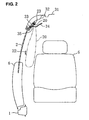
- the casing 23 having the collapsed or folded curtain 20 at least partly accommodated therein, as shown in FIG. 2, preferably is formed with a U-shaped cross section and supported via a bracket 33 (directly or indirectly) at or on a roof rail 32 extending substantially longitudinally along or near a side edge of a roof panel 31.
- the casing 23 preferably is covered by a head lining 34 from inside.
- a side edge of the head lining 34 is detachably engaged with a side lining 35 so that it can be off or be displaced or come off from the side lining 35 with an inflation force of the curtain 20 to generate a gap with the side lining 35.
- the curtain 20 is allowed to be inflated or enlarged or deployed through the gap, which will be formed between the head lining 34 and the side lining 35, into a cabin of the vehicle.
- the side lining 35 is supported via a welt at the roof panel 32 along with the roof rail 31.
- the tether 22 is illustrated in its position in a state where the curtain 20 is inflated for convenience, not in a state where the curtain 20 is accommodated in the casing 23.
- a second-window-side support pin or projection 36 and a third-window-side support pin or projection 37 are respectively disposed at a portion of the second window side that is away from the first window side and a portion of the third window side that is away from the first window side.
- these support pins 36, 37 are respectively disposed at a portion of the second window side that is away from the first window side and a portion of the third window side that is away from the first window side.
- one or more bands 38, 39 operative to provide a weak tension line at the curtain 20 in cooperation with the support pins 36, 37.
- a base-end portion of the curtain 20 is held at the casing 23 along the window side from the second window side to the first and third window sides.
- the curtain 20 is at least partly accommodated in the casing 23 at a side of the first window side relative to the support pins 36, 37.
- a range E shows an accommodation area of the tether 22 in the casing 23.
- the tether 22 is basically accommodated in the casing 23 in its substantially extended state (herein, there may be provided a partial slack at the tether).
- FIG. 3 shows the folded state of the curtain 20 and the tether 22 that are accommodated in the casing 23 at the second window side
- FIG. 4 shows the inflation state of the curtain 20.
- FIG. 3 shows the tether 22 to be located on a near side of the curtain 20 in order to provide an easy understanding of the accommodation state of the tether 22 in FIG. 3, the tether 22 is at least partly accommodated in back of the curtain 20 (i.e., on an outboard side).
- FIG. 3 shows the tether 22 to be located on a near side of the curtain 20 in order to provide an easy understanding of the accommodation state of the tether 22 in FIG. 3
- the tether 22 is at least partly accommodated in back of the curtain 20 (i.e., on an outboard side).
- a base-end portion of the band 38 at the second window side is connected to a middle or intermediate portion of a side face of the second-window-side inflatable portion 24 of the curtain 20 and its distal or tip-end portion is (directly or indirectly) connected to a distal or tip end of the second-window-side inflatable portion 24 of the curtain 20.
- the second-window-side support pin 36 as shown in FIG. 5, is provided to be supported preferably by both side walls of the casing 23 and disposed substantially perpendicularly to a window face in such a manner that it is located between the side face of the inflatable portion 24 and the band 38.
- the band 38 is at least partly accommodated in the casing 23 along the second-window-side inflatable portion 24 in such a manner that its distal or tip-end portion is located substantially on a lower face (a face substantially opposite to the first window side) of the support pin 36, like being wound up around the lower face, and its base-end portion is located on a side of the first window side relative to the support pin 36.
- the tip end of the band 38 also moves substantially toward the fourth window side and then the base-end portion of the band 38 engages with the second-window-side support pin 36.
- the inflated curtain 20 is restrained not only at its base-end portion by the casing 23, but at its side portion on the second window side by the support pin 36.
- the base-end portion of the band 38 constitutes an engagement portion 38a operative to engage with the support pin 36.
- a curtain length h1 from the fixed point 10 that is the closest to the support pin 36 at the base end of the side portion of the curtain 20 to the connecting point of the band 38 (namely, a length of the folded curtain in a state in which the curtain 20 is inflated) is set to be a length H1 (or longer) from the fixed point 10 to the support pin 36.
- a length of the band 38 is set to be a length of a corresponding part of the curtain 20 in the inflated state from the support pin 36 to the tip portion of the curtain side portion.
- the band 39 provided at the third window side has a similar structure to the second-window-side band 38 as shown in FIGS. 6 and 7. Namely, a base-end portion of the band 39 is (directly or indirectly) connected to a middle or intermediate portion of the side face (rear side face) of the third-window-side inflatable portion 25 and a tip-end portion of the band 39 is (directly or indirectly) connected to a portion near the tip portion of the inflatable portion 25.
- the third-window-side support pin 37 is, like the second-window-side support pin 36, is supported at the casing 23 and disposed substantially perpendicularly to the window face in such a manner that it is located between the side face of the inflatable portion 25 and the band 39.
- the band 39 is at least partly accommodated in the casing 23 along the third-window-side inflatable portion 25 in such a manner that its tip-end portion is located on a lower face (a face opposite to the first window side) of the support pin 37, like being wound up around the lower face, and its base-end portion is located substantially on a side of the first window side relative to the support pin 37.
- the tip end of the band 39 also moves substantially toward the fourth window side and then the base-end portion of the band 39 engages with the third-window-side support pin 37 (FIG. 7).
- the inflated curtain 20 is restrained not only at its base-end portion by the casing 23, but at its side portion on the third window side by the support pin 37.
- the base-end portion of the band 39 constitutes an engagement portion 39a operative to engage with the support pin 39.
- a tension provision portion comprised of the both support pins 36, 37 that provides the weak tension at the curtain 20.
- a substantially straight line connecting the both support pins 36, 37 constitutes a tension line 40 of the curtain 20 as shown in FIG. 1A.
- the tension line can be provided at the curtain 20 at a location that is away from the base end portion of the curtain 20 held at the casing 23, passengers can be prevented from getting out of or hitting the windows 2 - 4 improperly.
- the curtain 20 could get a desirably strong tension by properly adjusting the length of the curtain cloth (the length of the curtain 20 without the inflation of the inflatable portions 24 - 26).
- the tension line may be provided only with the tether 22, which will be described below.
- the tether 22 is provided, as shown in FIG. 8, such that its one end is (directly or indirectly) connected to the base-end portion of the band 38 and the other end is (directly or indirectly) connected to the base end portion of the band 39.
- This tether 22 is at least partly accommodated in the casing 23 beside the folded curtain 20 (on the outboard side) as shown in FIG. 9. Accordingly, both ends of the tether 22 move substantially toward the fourth window side along with the base-end portions of the bands 38, 39 according to the inflation of the curtain 20, and the tether 22 comes to be positioned beside and outside the inflatable portions 24 - 26 of the curtain 20 across the side window portion.
- the tether 22 is provided so as to extend substantially longitudinally along the above tension line 40.
- the tether 22 can become a backup for the curtain 20 (moving stopping).
- the tether 22 extending substantially longitudinally preferably is positioned at a level that is higher than a beltline of the vehicle body 1 and/or lower than upper ends of headrests of the seats 5, 7, 8. Thereby, the protection of the passengers 9 can be improved.
- the length of the tether 22 extending across the window portion is shorter than a length of its corresponding part of the curtain 20 in a state in which the curtain 20 is inflated without the inflation of the inflatable portions 24 - 26, i.e., a length at the tension line 40 (a length of the curtain cloth constituting an inboard face of the curtain 20 or a length of the curtain cloth constituting an outboard face of the curtain 20, which is shorter).
- the tether 22 can provide a greater (stronger) tension than the curtain 20, so the movement of the curtain 20 can be surely suppressed by the tether 22.
- the tether 22 extends substantially straight connecting portions near the both support pins 36, 37 in FIG. 1 B, the tension may not need so strong, as long as the tether 22 could suppress the outward movement of the curtain 20 effectively.
- the tether 22 can be backup for the curtain 20 and thereby the protection of the passengers can be maintained properly.
- the tether 22 can extend beside the inflatable portions 24 - 26, thereby preventing the inflation of the curtain 20.
- the tether 22 may be provided to interconnect respective portions near the engagement portions 38a, 39a of the inflatable portions 24, 25. Namely, the tether 22 can be provided to interconnect proper portions of the curtain 20, as long as the support pins 36, 37 related to the engagement portions 38a, 39a can support the tether 22 sufficiently.
- the tension of the tether 22 can be made stronger than the tension of the curtain 20 near the tether 22 by adjusting the length of the tether 22 to be shorter than the length of the curtain cloth constituting the inboard face of the curtain 20 or the length of the curtain cloth constituting the outboard face of the curtain 20, which is shorter.
- the tension of the curtain 20 itself can be weakened properly without deteriorating the protection by the curtain airbag.
- the curtain 20 can be smoothly moved inwardly (inboard) or outwardly (outboard) or bent along any longitudinally-extending line. Accordingly, the passengers can turn up the curtain 20 at any locations easily (see the curtain illustrated with a two-dotted broken line in FIG. 4), which can make it easy for the passengers to get out of vehicles through a space generated between the tether 22 and the window peripheral portion.
- the base-end portion of the curtain 20 folded at the first window side may be fixed to the vehicle body 1 directly without providing the casing. This modification can be also applied in other embodiments as well.
- FIG. 10 A primary part of the present embodiment is shown in FIG. 10. Other parts are similar or the same as the embodiment 1.
- a lobe portion 41 with a specified (predetermined or predeterminable) width is provided at the side portion of the curtain 20 along the second window side, instead of the band, and a slot (guide hole) 42 is formed at the lobe portion 41.
- This slot 42 is equivalent to the gap formed between the curtain 20 and the band in the embodiment 1.
- the support pin 36 is provided so as to get through the slot 42 like the embodiment 1.
- the tether 22 is (directly or indirectly) connected to the base-end portion (an end portion near the first window side) of the lobe portion 41.
- the side portion of the curtain 20 at the third window side is constituted like the portion at the above-described second window side.
- the support pin 36 is configured to be located at a tip portion of the slot 42 (on the side of the fourth window side) when the curtain is in the folded state. Then, according to the inflation of the curtain 20, the tip portion of the slot 42 is moved substantially toward the fourth window side, and the lobe portion 41 comes to engage with the support pin 36 at a base-end portion (engagement portion) 41 a of the slot 42.
- FIGS. 10 through 13 A primary part of the present embodiment is shown in FIGS. 10 through 13.
- the band 38 of the present embodiment is configured to be relatively long and the engagement portion 38a is configured to be located at the intermediate or substantially middle portion of the band 38 as shown in FIG. 11.
- the side portion of the curtain moves away from the support pin 36 substantially toward the center of the window portion, thereby generating an uncovered area 45 (space) between the second window side of the window portion and the curtain 20 (curtain body).
- Other basic parts are similar or the same as the embodiment 1.
- a range E is a accommodation area of the tether 22.
- the front-side inflatable portion 26 preferably is formed in an enlarged-width shape, unlike the embodiment 1, which extends substantially vertically beside the seat back of the driver's seat 5.
- the inflatable portion 26 beside the driver's seat 5 constitutes the side inflatable portion.
- the base-end portion of the band 38 is (directly or indirectly) connected to a connecting portion of the base end of the curtain 20, e.g., the base end of the inflatable portion 26 (near the fixed point 10 that is the closest to the support pin 36) to the casing 23, and the distal or tip-end portion of the band 38 is (directly or indirectly) connected to the tip portion of the front-side inflatable portion of the curtain 20, e.g., the front tip end of the inflatable portion 26.
- the base-end portion of the band 38 may be (directly or indirectly) (directly or indirectly) connected to the casing 23 or the window portion that is near the above fixed point.
- the band 38 is at least partly accommodated in the casing 23 in such a manner that a middle or intermediate portion of the band 38 is wound up around or engaged with the support pin 36 and the band 38 has loosened without a tension.
- the engagement portion 38a of the band 38 is located away from the support pin 36 toward the first window side, and one end of the tether 22 is (directly or indirectly) connected to the engagement portion 38a (part of the tether 22 is not illustrated in the figure). Then, according to the inflation of the curtain 20, the distal or tip portion of the inflatable portion 26 of the curtain 20 is moved substantially toward the fourth window side and thereby the engagement portion 38a of the band 38 is moved substantially to the support pin 36.
- the engagement portion 38a of the band 38 comes to engage with the support pin 36, in which the band 38 is bent substantially in a L shape, when viewed from the vehicle side, with its both ends constituting support points as shown in FIG. 13.
- the tether 22 is provided to extend substantially rearward from a location of the support pin 36 with a tension.
- the base-end portion of the band 39 is provided to engage with the support pin 37 like the embodiment 1.
- a length L1 of the band 38 from the support pin 36 to the connecting point to the tip portion of the curtain 20 when the curtain is inflated is set be preferably about a half of a length L2 of the curtain 20 from the fixed point 10 to the tip portion of the curtain 20 or longer.
- the tension line 40 that interconnects the base end of the inflatable portion 26 supported at the casing 23 and the support pin 37 located at the third window side.
- the tether 22 can be the backup for the curtain 20 like the embodiment 1.
- the band 38 may not prevent the curtain 30 from being turned up in a case where the curtain 20 is turned up for allowing passengers or objects to get out of vehicles before the inflatable portion 26 shrinks after the inflation.
- the inflatable portion 26 of the curtain 20 can be turned up around the fixed point 10 widely so that the tip portion of the curtain 20 can be sufficiently away from the window portion to the first window side. Thereby, the curtain 20 can be turned up widely, which can make it easy for passengers or objects to get out of vehicles.
- the windows 2, 3 of the front door 6 and the side door 16 are generally configured to open widely. And, passengers may escape through the windows 2, 3 (by lowering or breaking window panes) in an emergency.
- the front portion of the curtain 20 substantially corresponding to the windows 2, 3 is easily turned up, the above escape of passengers can be properly attained.
- the uncovered area 45 between the front-side inflatable portion 26 of the inflated curtain 20 and the second window side of the window portion the wide space for escape can be generated when the curtain 20 is turned up. Further, this uncovered area 45 could be an appropriate target for passengers looking for the escape area.
- the tension of the curtain 20 near the tether 22 can be made weak by adjusting the length of the tether 22 to be shorter than the length of the curtain cloth constituting the inboard face of the curtain 20 or the length of the curtain cloth constituting the outboard face of the curtain, which is shorter, or by adjusting the length of the lower end (lower window side) of the curtain 20 to be relatively long: Accordingly, it can be easy for the passengers to get out of vehicles.
- the front end of the base-end portion of the curtain may be supported at the casing 23 at the first window side.
- the rear end of the base-end portion of the curtain may be supported at the casing 23 at the first window side, which can provide the same effects.
- the angle formed between the first window side and the second window side be about 90 degrees or more and about 180 degrees or less.
- FIGS. 14 through 16 show primary parts of the present embodiment.
- a distinction from the embodiment 3 is that the base-end portion of the side portion of the curtain 20 at the second window side is fixed to a border of the first window side with the second window side of the periphery of the window portion, thereby generating the wide uncovered area 45 between the curtain 20 and the second window side.
- the range E in FIG. 14 shows the accommodation area of the tether 22.
- the length L1 of the band 38 from the support pin 36 to the connecting point to the front-side tip portion of the curtain 20 when the curtain is inflated is set be about a half of the length L2 of the curtain 20 from the fixed point 10 to the tip portion of the curtain 20 or longer.
- the substantially same effects as the embodiment 3 can be provided.
- the curtain since the wide uncovered area 45 is generated between the curtain 20 and the second window side by fixing the base-end portion of the side portion of the curtain 20 to the border of the first window side with the second window side, the curtain can be turned up widely, thereby making it easy for passengers or objects to get out of vehicles.
- FIGS. 17 through 19 show primary parts of the present embodiment.
- the second window side of the window portion is substantially straightly inclined.
- the fixed point 10 of the base end of the side portion of the curtain 20 is located at the middle or intermediate position of the second window side.
- the front end of the curtain 20 is fixed to the second window side via a fixing tether 48.
- one end of the band 39 is (directly or indirectly) connected to the middle or intermediate portion of the side portion of the curtain 20 and the other end is (directly or indirectly) connected to the tip portion of the side portion of the curtain 20, in which the end portion of the band 39 is at least partly wound up around the support pin 37, which is similar to the embodiment 1.
- the band 39 has loosened without a tension.
- One end of the tether 22 is (directly or indirectly) connected to a peripheral portion of the curtain 20 near the fixed point 10 at the second window side, and the other end of the tether 22 is (directly or indirectly) connected to the middle or intermediate portion of the curtain at the third window side (to the portion which the base-end portion of the band 39 is connected).
- the range E in FIG. 14 shows the accommodation area of the tether 22 in FIG. 17.
- the other end of the tether 22 may be (directly or indirectly) connected to a portion near the fixed portion of the fixing tether 48 at the second window side, or to the fixing tether 48 as shown in two-dotted broken lines in FIG. 18.
- the curtain 20 when the curtain 20 is inflated, the curtain 20 is made extend with a certain tension by the band 38 at the second window side, and the base-end portion of the band 39 engages with the support pin 37, thereby restraining the curtain side portion by support pin 37 at the third window side.
- the tether 22 extends substantially in a direction of connecting the fixed point 10 at the second window side and the support pin 37 at the third window side across the window portion.
- the tether 22 can be the backup for the protection by the curtain 20 in the present embodiment as well, so the protection of the passengers can be attained surely. Also, since the band 39 has loosened without a tension at the third window side in the folded state of the curtain, the length of the extending curtain 20 from the support pin 37 can be made properly long even if the support pin 37 is located near the first window side. Thus, providing the curtain 20 extending beyond the fourth window side can be properly attained. Likewise, the escape area can be generated by turning up the curtain 20 after the inflation of the curtain 20.
- the present embodiment which is shown in FIG. 20, is an example in which the present invention is applied to a back window at a back door 51 of the vehicle.
- This back window portion 52 preferably is formed in a quadrilateral shape, which comprises a first window side (upper window side) that is comprised of a roof-rear periphery of the vehicle 1, second and third window sides that are comprised of both fourth pillars 14, and a fourth window side that is comprised of a lower edge of the back window.
- the curtain airbag device is configured to at least partly cover the back window portion.
- the curtain airbag device includes the curtain 20, inflator 21 and tether 22 like the embodiment 1.
- the curtain 20 is folded or collapsed and at least partly accommodated in the casing 23 at an area from the first window side to upper portions of the second and third window sides of the back window portion.
- the curtain 20 comprises an inflatable portion 24 that extends substantially vertically along the second window side, an inflatable portion 25 that extends substantially vertically along the third window side and a central or intermediate inflatable portion 26 that extends substantially vertically at the center or intermediate position of the back window portion.
- These inflatable portions 24 - 26 are connected to each other via a (preferably substantially upper) inflatable portion that extends substantially longitudinally preferably at or near an upper portion of the curtain 20. Adjacent inflatable portions are at least partly coupled via non-inflatable webs 27.
- the curtain 20 is, as shown in FIG.
- the curtain 20 may be configured in such a manner that its tip portion goes substantially downward preferably beyond the fourth window side of the back window portion.
- the inflator 21, which is similar to or substantially the same as that of the embodiment 1, is coupled to the (upper) inflatable portion of the curtain 20 via at least one pipe 28.
- the controller operates the inflator 21 based on outputs of the above one or more sensor to detect the specified state of the vehicle.
- the casing 23, which is similar to or substantially the same as that of the embodiment 1, is supported at or near the roof rail and at least partly covered by the head lining from inside, and inflated or inflatable into the cabin, getting out of a gap that may be formed at the head lining by the inflation force of the curtain 20.
- a second-window-side support pin 36 and a third-window-side support pin 37 are provided at both lower ends of the casing 23 substantially extending downward along the second and third window sides.
- bands 38, 39 operative to provide tension line at the curtain 20 in cooperation with the support pins 36, 37.
- a base-end portion of the curtain 20 is held at the casing 23 along the window side from the second window side to the first and third window sides.
- a reference numeral 10 denotes fixed points 10 that fix the base-end portions of the curtain to the casing 23.
- the support pins 36, 37 preferably are located substantially below the fixed points 10 at the second and third window sides.
- the bands 38, 39 are respectively provided in such a manner that their base-end portions are (directly or indirectly) connected to respective middle or intermediate portions of the side faces of the inflatable portions 24, 25 at the second and third window sides of the curtain 20 and their distal or tip-end portions are (directly or indirectly) connected to respective tip portions of the inflatable portions 24, 25.
- the support pins 36, 37 are provided in a similar or the substantially same way as those of the embodiment 1 so as to get through between the side faces of the inflatable portions 24, 25 and the bands 38, 39.
- the bands 38, 39 are at least partly accommodated in the casing 23 along the inflatable portions 24, 25 in such a manner that their distal or tip-end portions are located on the lower faces of the support pins 36, 37 and their base-end portions are located on a side of the first window side relative to the support pins 36, 37.
- the tip-end portions of the bands 38, 39 move toward the fourth window sides and their base-end portions come to engage with the support pins 36, 37.
- the both side portions of the curtain 20 are restrained by the pins 36, 37, so the support pins 36, 37 constitute or form part of a tension applying portion that applies the tension to the curtain 20.
- the tension line 40 connecting the both support pins 36, 37 is provided at the curtain 20.
- One end of the tether 22 is (directly or indirectly) connected to the base-end portion of the second-window-side band 38 and the other end of the tether 22 is (directly or indirectly) connected to the base-end portion of the third-window-side band 39, and the tether 22 is at least partly accommodated beside (on the outboard side) the curtain 20 in the casing 23 like the embodiment 1.
- a range E shows an accommodation area of the tether 22.
- both ends of the tether 22 move toward the support pins 36, 37 along with the base-end portions of the bands 38, 39 according to the inflation of the curtain 20, and the tether 22 comes to be positioned beside and/or outside the inflatable portions 24 - 26 of the curtain 20 across the side window portion, namely, it comes to substantially extend laterally along the tension line 40.
- a relationship between the length of the tether 22 extending substantially across the window portion and the length of its corresponding portion of the curtain 20 preferably is the same as that of the embodiment 1.
- the tether 22 can be backup for the curtain 20 and thereby the protection of the passengers can be maintained properly.
- the present embodiment which is shown in FIGS. 21 and 22, is an example in which the present invention is applied to a roof window portion of the vehicle. Namely, at a roof 60 of the vehicle body 1 is preferably provided a substantially quadrilateral-shaped roof window 61, and a curtain airbag device is configured to at least partly cover the roof window portion.
- the curtain airbag device comprises first and second curtains 20A, 20B with inflatable portions that are inflated by the gas supplied, one or more inflators 21A, 21 B as the gas supply device to supply the gas to the inflatable portions of the curtains 20A, 20B, and tethers 22A, 22B provided at the curtains 20A, 20B.
- the first curtain 20A is folded and at least partly accommodated in a substantially bent or L-shaped casing 23A that is provided substantially along or near the first and second window sides of the roof window portion
- the second curtain 20B is folded and accommodated in a substantially bent or L-shaped casing 23B that is provided substantially along or near the third and fourth window sides of the roof window portion.
- Each of the curtains 20A, 20B has both-side inflatable portions 24, 25 and a central or intermediate inflatable portion 26 that extend substantially across a diagonal line connecting a corner between the first and fourth window sides and a corner between the second and third window sides. Adjacent inflatable portions are at least partly coupled via non-inflatable webs.
- the curtains 20A, 20B are inflated in such a manner that both distal or tip ends at least partly lap over each other vertically.
- the respective central portions 26 of the curtains 20A, 20B are inflated so as to at least partly lap over the non-inflatable webs 27. Since the both-side inflatable portions 24, 25 of the curtains 20A, 20B at least partly lap over each other, their tip portions may be configured to be relatively thin as shown in FIG. 22.
- the inflatable portions 24 - 26 of the curtains 20A, 20B are connected to each other.
- the inflators 21A, 21 B which are similar or substantially the same as that of the embodiment 1, are coupled to the one or more inflatable portions 24 - 26 of the curtains 20A, 20B via respective pipes 28.
- the controller operates the inflators 21A, 21 B based on output(s) of the above sensor(s) to detect or predict the specified (predetermined or predeterminable) state of the vehicle.
- the casings 23A, 23B which are substantially the same as that of the embodiment 1, are (directly or indirectly) supported at or on or near the roof rail and at least partly covered by the head lining from inside, and inflated or inflatable into the cabin, getting out of gaps that may be formed at the head lining by the inflation force of the curtains 20A, 20B.
- a reference numeral 10 in FIG. 21 denotes fixed points 10 that fix the base-end portions of the curtains 20A, 20B to the casings 23A, 23B.
- the fixed points 10 at or near the both ends of the casing 23A are located at portions that are away or distanced from the support pins 36, 37 substantially toward the corner between the first and second window sides.
- the fixed points 10 at the both ends of the casing 23B are also located at portions that are away from the support pins 36, 37 toward the corner between the third and forth window sides.
- the bands 38, 39 are respectively provided in such a manner that their base-end portions are (directly or indirectly) connected to respective middle or intermediate portions of the side faces of the inflatable portions 24, 25 and their distal or tip-end portions are (directly or indirectly) connected to respective tip portions of the inflatable portions 24, 25.
- the support pins 36, 37 are supported at the casings 23A, 23B at an angle different from 0° or 180°, preferably substantially in perpendicular to the window pane so as to get through between the side faces of the inflatable portions 24, 25 and the bands 38, 39.
- the bands 38, 39 are at least partly accommodated in the casing 23A substantially along the inflatable portions 24, 25 in such a manner that their distal or tip-end portions are located preferably substantially on the center of the casing 23A relative to the support pins 36, 37 and their base-end portions are located on a face of the support pins 36, 37 that is directed to the casing 23B.
- the bands 38, 39 on the side of the curtain 20B are also at least partly accommodated in the casing 23B along the inflatable portions 24, 25 in such a manner that their distal or tip-end portions are located preferably substantially on the center of the casing 23B relative to the support pins 36, 37 and their base-end portions are located on a face of the support pins 36, 37 that is directed to the casing 23A.
- the inflatable portions 24, 25 of the curtains 20A, 20B are inflated with the gas supplied, their tip portions move substantially toward each other and the tip-end portions of the bands 38, 39 also move substantially toward each other and their base-end portions come to engage with the support pins 36, 37.
- the both side portions of the curtains 20A, 20B are restrained by the pins 36, 37, so the support pins 36, 37 constitute a tension applying portion that applies the tension to the curtains 20A, 20B.
- respective tension lines connecting the both support pins 36, 37 are provided at the curtains 20A, 20B.
- Respective one ends of the tethers 22A, 22B are (directly or indirectly) connected to the base-end portions of the band 38 and the other ends of the tethers 22A, 22B are (directly or indirectly) connected to the base-end portions of the band 39.
- the tethers 22A, 22B are at least partly accommodated beside (on the outboard side) the curtains 20A, 20B in the casings 23A, 23B.
- a range E shows an accommodation area of the tethers 22A, 22B.
- both ends of the tethers 22A, 22B move along with the base-end portions of the bands 38, 39 according to the inflation of the curtains 20A, 20B, and the tethers 22A, 22B come to be positioned beside and/or outside the inflatable portions 24 - 26 of the curtains 20A, 20B substantially across the roof window portion, namely, they come to substantially extend laterally along the tension line.
- a relationship between the length of the tethers 22A, 22B extending across the window portion and the length of its corresponding portion of the curtains 20A, 20B is similar or the same as that of the embodiment 1.
- the tethers 22A, 22B can be backup for the curtains 20A, 20B and thereby the protection of the passengers can be maintained properly.
- the present embodiment which is shown in FIG. 23, is an example in which the present invention is applied to the roof window portion of the vehicle like the embodiment 7. It is a only difference from the embodiment 7 that the preferably substantially quadrilateral-shaped roof window 61 is at least partly covered by a single curtain.
- the curtain airbag device comprises the curtain 20 with one or more inflatable portions, the inflator(s) 21, and the tether(s) 22. like the embodiment 1,
- the curtain 20 is folded and at least partly accommodated in a substantially bent or L-shaped casing 23 that is provided substantially along the first and second window sides of the roof window portion.
- the curtain 20 comprises a first inflatable portion 62 that extends substantially along the first window side and a second inflatable portion 63 that extends substantially along the third window side. Adjacent inflatable portions are at least partly coupled via a non-inflatable web 64.
- the inflatable portions 62, 63 are connected to each other on the side of the second window side.
- the inflator 21, which is similar or substantially the same as that of the embodiment 1, is coupled to the inflatable portion of the curtain via at least one pipe 28.
- the controller operates the inflator 21 based on output(s) of the above sensor(s) to detect or predict the specified (predetermined or predeterminable) state of the vehicle.
- the casing 23, which is similar or substantially the same as that of the embodiment 1, is (directly or indirectly) supported at an inside of the roof and/or at least partly covered by the head lining from inside, and inflated or inflatable into the cabin, getting out of a gap that may be formed at the head lining by the inflation force of the curtain 20.
- the casing 23 has an extension portion that projects from a second-window-side end substantially in parallel to the first window side, and the support pin 36 as a support portion is provided at this extension portion. Meanwhile, at the side of the inflatable portion 63 of the curtain 20 is provided at least one band 38 operative to provide a tension line at the curtain 20 in cooperation with the support pin 36. A base-end portion of the curtain 20 is held at a portion of the casing 23 from a substantially entire area of the first window side to a central or intermediate portion of the second window side.
- a reference numeral 10 denotes fixed points.
- the band 38 is provided in such a manner that its base-end portion is (directly or indirectly) connected to the side face of the second inflatable portion 63 and its distal or tip-end portion is (directly or indirectly) connected to a tip portion of the inflatable portion 63.
- the support pin 36 is supported at the casing 23 at an angle different from 0° or 180°, preferably substantially in perpendicular to the window pane so as to get through between the side face of the inflatable portion 63 and the band 38.
- the band 38 is at least partly accommodated in the casing 23 substantially along the inflatable portion 63 in such a manner that its distal or tip-end portion is located substantially on the first window side relative to the support pin 36 and its base-end portion is located substantially on a face of the support pin 36 that is directed to the third window side (a side substantially facing the second window side).
- the inflatable portion 63 of the curtain 20 is inflated with the gas supplied, its tip portion moves substantially toward the third window side and the tip-end portion of the band 38 also moves substantially toward the third window side and its base-end portion comes to engage with the support pin 36.
- the side portion of the second inflatable portion of the curtain 20 is restrained by the pin 36, so the support pin 36 constitutes a tension applying portion that applies the tension to the curtain 20.
- the tension line connecting the pin 36 and the end portion of the casing 23 on the side of the first window side that supports the base end portion of the curtain 20 is provided at the curtain 20.
- One end of the tether 22 is (directly or indirectly) connected to the base-end portion of the band 38 and the other end of the tether 22 is (directly or indirectly) connected to the end of the casing 23 on the side of the first window side.
- the tether 22 is at least partly accommodated beside (on the outboard side) the curtain 20 in the casing 23.
- a range E shows an accommodation area of the tether 22.
- the end of the tether 22 moves along with the base-end portion of the band 38 according to the inflation of the curtain 20, and the tether 22 comes to be positioned substantially beside and outside the inflatable portions 62, 63 of the curtain 20 substantially across the roof window portion, namely, they come to extend laterally along the tension line.
- a relationship between the length of the tether 22 extending substantially across the window portion and the length of its corresponding portion of the curtain 20 preferably is the same as that of the embodiment 1.
- the tether 22 can be backup for the curtain 20 and thereby the protection of the passengers can be maintained properly.
- the present embodiment which is schematically shown in FIG. 24A, 24B, relates to a curtain airbag device for at least partly covering a triangular window portion 71.
- the curtain airbag device comprises the curtain 20 with at least one inflatable portion (not illustrated) that is inflated by the gas supplied, the inflator 21 as a gas supply device to the gas to the curtain 20, and the tether 22 provided at the curtain 20.
- the curtain 20 is folded or collapsed and at least partly accommodated at a portion that is located from the first window side (the upper side in FIG. 24) to a middle or intermediate portion of the second window side (the left side in the figure) of the triangular window portion.
- the inflator 21, which is similar or substantially the same as that of the embodiment 1, is coupled to the inflatable portion of the curtain via one or more pipes 28.
- the controller operates the inflator 21 based on output(s) of the above sensor(s) to detect or predict at least partly the specified (predetermined or predeterminable) state of the vehicle.
- a support pin 36 as the support portion at a location that is away from the first window side (at a location that is farther away from the first window side than the fixed point of the base-end portion of the curtain).
- a band 38 operative to provide a tension line at the curtain 20 in cooperation with the support pin 36.
- the band 38 is provided in such a manner that its base-end portion is (directly or indirectly) connected to the side face of the curtain 20 on the side of the second window side and its distal or tip-end portion is (directly or indirectly) connected to a tip portion of the side face of the curtain 20 on the side of the second window side.
- the support pin 36 is supported at an angle different from 0° or 180°, preferably substantially in perpendicular to the window pane so as to get through between the side face of the curtain 20 and the band 38.
- the band 38 is at least partly accommodated in such a manner that its distal or tip-end portion is located on the first window side relative to the support pin 36 and its base-end portion is located on a face of the support pin 36 that is directed substantially to an opposite side to the first window side.
- the curtain 20 is inflated with the gas supplied, as shown in FIG. 24B, its tip portion on the side of the second window side moves substantially away from the first window side so as to at least partly cover the triangular window portion 71.
- the tip-end portion of the band 38 also moves likewise and its base-end portion comes to engage with the support pin 36.
- the side portion of the curtain 20 on the side of the second window side is restrained by the support pin 36, so the support pin 36 constitutes a tension applying portion that applies the tension to the curtain 20.
- the tension line connecting the support pin 36 and the end portion on the side of the first window side that supports the base end portion of the curtain 20 is provided at the curtain 20.
- One end of the tether 22 is (directly or indirectly) connected to the base-end portion of the band 38 and the other end of the tether 22 is (directly or indirectly) connected to the end portion on the side of the first window side.
- the tether 22 is at least partly accommodated beside (on the outboard side) the curtain 20. Accordingly, the end of the tether 22 moves along with the base-end portion of the band 38 according to the inflation of the curtain 20, and the tether 22 comes to be positioned substantially beside and outside the curtain 20 substantially across the window portion, namely, they comes to substantially extend laterally along the tension line.
- a relationship between the length of the tether 22 extending across the window portion and the length of its corresponding portion of the curtain 20 preferably is the same as that of the embodiment 1.
- the tether 22 can be backup for the curtain 20 and thereby the protection of the passengers can be maintained properly.
- the present invention should not be limited to the above embodiments 1 through 9, but can be applied to any curtain airbag devices for window portions or openings (entrance and exit) of trains, aircrafts, ships, space vehicles and buildings other than automotive vehicles.
- Any hook, support hole or the like, instead of the support pin, may be used to restrain the side portion of the curtain as the support portion.
- the band and the tether should not be limited to a particular shape, and any kind of shape may be used, such as a string shape or a belt shape.
- the tether may be comprised of a wide sheet. Namely, in the state shown in FIG. 18 where the tether extends to interconnect the fixed portion 10 at the second window side and the support portion corresponding to the support pin 37 when the curtain airbag is inflated, the tether is made of a wide sheet and it may be configured to cover substantially an upper part of the curtain 20 with its one or more fixing points to the first window side.
- the fixing points of the sheet tether may be provided at a vehicle body at the first window side or the curtain near the first widow side.
Abstract

Description
- The present invention relates to a curtain airbag device that promptly covers a window portion of a vehicle, such as an automotive vehicle, train, ship, aircraft, or space vehicle, or a structure, such as a house, building, or space station.
- A curtain airbag device, in which a curtain-shaped airbag is accommodated at a periphery of a window portion of a vehicle and the airbag is inflated by gas that is supplied at a vehicle crash or a rollover so as to cover the window portion promptly, is generally known. In this device, a passenger could not be protected properly by the curtain airbag device unless a proper tension is provided at the curtain. For example, in a case where the curtain is folded and accommodated at a portion along one window side and both window sides next to this window side of a rectangular window portion, the curtain may be inflated with its tip portion having a total length of these three window sides. Namely, the length of the free tip portion of the curtain inflated becomes relatively long, so the curtain tends to be turned up even with a relatively small force applied. As a result, the protection of the passenger could not be properly attained.
- In view of the above problem, there are generally provided a plurality of inflatable portions (bags) that extend from one window side of the window portion toward the tip portion of the curtain so that an entire width of the curtain in an inflated state can be reduced by these inflatable portions, namely the length of the free tip portion of the curtain can be shorter, thereby providing a large tension at the curtain. However, it may be difficult to obtain a sufficiently large enough tension. Further, since a considerably large inflatable portions may be required to cover a large window portion, a large-sized inflator may be also necessary to supply a large amount of gas to the large inflatable portions. Thereby, application of the curtain airbag device to the large window portion would be difficult.
-
US Patent Application Publication No. 2004/0066022 A1 discloses a curtain airbag device for a vehicle back window, in which a curtain portion is placed in the folded state at an upper peripheral portion of the back window and tension-providing support points are provided respectively at middle portions of the both-side peripheral portions of the back window, wherein the curtain portion is inflated downward from the tension-providing support points, thereby generating the tension with the tension-providing support points. - The above-described patent publication also discloses another curtain airbag device, in which there are provided guide rails extending vertically at the both-end portions of the back window, wherein the curtain portion placed at the upper peripheral portion is moved down along the guide rails, thereby lowering a tension line by moving the tension-providing support points downward.
- However, in a case where the tension line is lowered by moving down the tension-providing support points as described above, a distance between both tension-providing portions by way of the upper peripheral portion of the window portion becomes relatively long. Namely, the length of the curtain located between the tension-providing portions (the width of the curtain) in the inflated state becomes considerably long, and therefore a large amount of gas supply would be required to inflate the large inflatable portions for generating a desirable tension properly.
- Further, since the tension-providing portions move as described above, the guide rails would generate a sliding resistance for the inflation of the curtain. Thereby, a smooth and prompt inflation of the curtain could not be attained properly.
- In view of the above-described problems, the present invention has an object to provide a curtain airbag device that can prevent a curtain from being moved improperly by pushing and thereby protect any persons or objects in vehicles or structures surely.
- This object is solved by the curtain airbag device according to the present invention of
claim 1. Preferred embodiments of the present invention are subject of the dependent claims. - According to the present invention, there is provided a curtain airbag device, which is applicable to a window portion having one or more windows, comprising at least one curtain including at least one inflatable portion, the curtain being configured to be at least partly accommodated at least at a first window side of a periphery of the window portion in a collapsed state the collapsed state being a state in which the curtain is reduced in size or collapsed e.g. by being folded in a regular or irregular way, folded in a roll shape or collapsed in a different way (such as folded in a irregular or chaotic way) and to be inflated so as to at least partly cover at least part of the window portion with the inflatable portion to which gas is supplied, a gas supply device operative to supply the gas to the inflatable portion(s) of the curtain, a support portion provided at a specified (predetermined or predeterminable) portion of a second window side that is provided next to the first window side, the specified (predetermined or predeterminable) portion being located substantially away from the first window side, an engagement portion provided at a side portion of the curtain that is located on a side of the second window side, the engagement portion being configured so as to be located at a position that is substantially closer to the first window side relative to the support portion in the collapsed (preferably folded) state of the curtain and to be moved toward the support portion so as to engage with the support portion as a tip portion of the curtain moves in an inflation direction according to the inflation of the curtain, and a tether, one end of which is (directly or indirectly) connected to the engagement portion or a portion near the engagement portion of the curtain and the other end of which is (directly or indirectly) connected to a specified (predetermined or predeterminable) portion of the periphery of the window portion other than the second window side or a peripheral portion of the curtain that is restrained by the specified (predetermined or predeterminable) portion of the periphery of the window portion when the curtain is in the inflated state, the tether being configured so as to be at least partly accommodated at the periphery of the window portion with the curtain and to substantially extend according to the inflation of the curtain from a side of the support portion to a side of the specified (predetermined or predeterminable) portion of the periphery of the window portion across the window portion, whereby a tension can be provided to the curtain.
- Accordingly, when the gas is supplied to the inflatable portion of the curtain, the tip portion of the curtain moves substantially in the inflation direction according to the inflation of the curtain. Thereby, the engagement portion is moved substantially along the window periphery from the first window side to the second window side, and engages with the support portion provided at the second window side. Thus, the side portion of the curtain is restrained by the support portion.
- Meanwhile, since it is (directly or indirectly) connected to the engagement portion or the portion near the engagement portion of the curtain, the tether's one end is moved substantially toward the support portion according to the curtain inflation, thereby the tether extends, substantially across the window portion, from the side of the support portion to the side of the specified (predetermined or predeterminable) portion of the periphery of the window portion. Accordingly, the tether can prevent the curtain from being moved improperly by pushing, and thus any persons or objects in vehicles or structures can be surely protected.
- Further, since the tether's one end is moved to the support portion of the second window side along with the engagement of the curtain according to the curtain inflation, there may be no need for any moving device like a guide rail. Thus, the structure can be made simpler.
- Herein, the present curtain airbag device may be applied to any window portions having any overall shape, such as triangle, quadrilateral, or any other polygon, and any side line, such as straight line or curved line.
- The tether may be provided so as to be located inside or outside the curtain.
- The specified (predetermined or predeterminable) portion of the periphery of the window portion other than the second window side, to which the tether's other end is (directly or indirectly) connected, may be the first window side or any other window side. Also, the other end of the tether may be (directly or indirectly) connected to the portion near the first window side or a portion near another window sides. Further, the support portion may be provided at another window side that is located substantially facing the second window side, and the engagement portion that is moved along this window side facing the second window side according to the curtain inflation so as to engage with this support portion may be provided at the curtain. Herein, the other end of the tether may be (directly or indirectly) connected to this engagement portion or a portion near this engagement portion.
- The curtain may be provided to preferably cover a substantially entire area of the window portion or a partial area of the window portion. In a case where the curtain covers partially the window portion, an uncovered area can be generated, and so this uncovered area generated may facilitate letting any persons or objects get out of this uncovered area outside vehicles or structures.
- Further, the curtain may be at least partly accommodated at the first window side in a state where it is collapsed (preferably folded in bellows shape or roll shape).
- According to an embodiment of the present invention, the support portion comprises a second-window-side support portion and a third-window-side support portion, the second-window-side support portion being provided at the specified (predetermined or predeterminable) portion of the second window side, the third-window-side support portion being provided at another specified (predetermined or predeterminable) portion of a third window side that is provided next to the first window side on an opposite side to the second window side and the specified (predetermined or predeterminable) portion of the third window side being located away from the first window side, the engagement portion comprises a second-window-side engagement portion and a third-window-side engagement portion, the second-window-side engagement portion being provided at the side portion of the curtain that is located on the side of the second window side and being configured so as to be located at the position that is substantially closer to the first window side relative to the second-window-side support portion in the collapsed (preferably folded) state of the curtain and to be moved substantially toward the second-window-side support portion so as to engage with the second-window-side support portion as the tip portion of the curtain moves substantially in the inflation direction according to the inflation of the curtain, the third-window-side engagement portion being provided at a side portion of the curtain that is substantially located on a side of the third window side and being configured so as to be located at a position that is substantially closer to the first window side relative to the third-window-side support portion in the collapsed (preferably folded) state of the curtain and to be moved substantially toward the third-window-side support portion so as to engage with the third-window-side support portion as the tip portion of the curtain moves in the inflation direction according to the inflation of the curtain, and the tether connects the second-window-side engagement portion or a portion near the second-window-side engagement portion of the curtain to the third-window-side engagement portion or a portion near the third-window-side engagement portion of the curtain, the tether being configured so as to be at least partly accommodated at the periphery of the window portion with the curtain and to extend according to the inflation of the curtain substantially across the window portion from the second window side to the third window side, whereby a tension can be provided to the curtain between the second-window-side support portion and the third-window-side support portion.
- Namely, according the above embodiment, the second-window-side engagement portion is moved from the side of the first window side substantially toward the second-window-side support portion so as to engage with the second-window-side support portion according to the inflation of the curtain, and the third-window-side engagement portion is moved from the side of the first window side substantially toward the third-window-side support portion so as to engage with the third-window-side support portion according to the inflation of the curtain. And, the tether extends substantially across the window portion from the second-window-side support portion to the third-window-side support portion.
- Accordingly, since it is disposed along a tension line connecting the both support portions with the engagement of the respective support portions and the respective engagement portions, the tether can prevent the curtain from being moved improperly by pushing, and thus any persons or objects in vehicles or structures can be surely protected.
- According to another embodiment of the present invention, the curtain is configured to be at least partly accommodated at least at the first window side and the second window side of the periphery of the window portion in the collapsed (preferably folded) state, the engagement portion is provided at the curtain, a length of the tether extending substantially across the window portion is configured to be shorter than a length of a corresponding part of the curtain in a state in which the curtain is inflated without the inflation of the inflatable portion.
- Thereby, since the tether has a stronger tension than the curtain, backup of the protection by the curtain can be improved.
- According to another embodiment of the present invention, the curtain is configured to at least partly cover the window portion of a vehicle, and the tether is configured to extend substantially outside the inflatable portion of the curtain in the inflated state.
- Thereby, since the passenger may be supported by the tether via the curtain, without direct contacting, the protection of the passenger's body can be improved. Further, when the passenger moves the curtain toward the first window side, it becomes easy for the passenger to get out of a space between the tether and the window periphery outside the vehicle.
- According to another embodiment of the present invention, the tether is configured to extend substantially beside the inflatable portion of the curtain in the inflated state.
- Thereby, since the tension line may not be provided substantially at the curtain itself, the smooth gas supply to the inflatable portion can be obtained and thereby the inflation of the inflatable portion can be attained. Thus, the smooth and proper inflation of the curtain can be improved.
- According to another embodiment of the present invention, a band is provided substantially at a side portion of the curtain, a base-end portion of the band is (directly or indirectly) connected to a middle or intermediate portion of the side portion of the curtain and a tip-end portion of the band is (directly or indirectly) connected to a portion that is located at a side of the tip portion of the curtain relative to the middle or intermediate portion of the side portion of the curtain, the support portion is configured to be located substantially between the side portion of the curtain and the band such that the tip-end portion of the band is located on a side of the support portion that is substantially opposite to the first window side in the collapsed (preferably folded) state of the curtain and the base-end portion of the band as the engagement portion is moved toward the support portion so as to engage with the support portion according to the inflation of the curtain.
- Thereby, the tip-end portion of the band is moved substantially forward in the inflation direction along the second window side according to the inflation of the curtain without any interfering with the support portion. Accordingly, the forward movement of the tip of the side portion of the curtain can be properly conveyed to the band at the curtain inflation, and thereby the engagement of the engagement portion with the support portion can be attained smoothly. Thus, the inflation of the curtain, provision of the tension line, and extension of the tether can be attained smoothly.
- According to another embodiment of the present invention, a band is provided at a side portion of the curtain, a base-end portion of the band is (directly or indirectly) connected to a fixed portion that is fixed at the periphery of the window portion or a portion near the fixed portion of the periphery of the window portion and a tip-end portion of the band is (directly or indirectly) connected to the tip portion of the side portion of the curtain, the support portion is configured to be located substantially between the side portion of the curtain and the band such that the tip end of the band is located substantially on a side of the support portion that is substantially opposite to the first window side in the collapsed (preferably folded) state of the curtain and a middle or intermediate portion of the band as the engagement portion is moved toward the support portion so as to engage with the support portion according to the inflation of the curtain.
- Thereby, the tip-end portion of the band is moved substantially forward in the inflation direction substantially along the second window side according to the inflation of the curtain without any interfering with the support portion. Accordingly, the forward movement of the tip of the side portion of the curtain can be properly conveyed to the band at the curtain inflation, and thereby the engagement of the engagement portion with the support portion can be attained smoothly. Thus, the inflation of the curtain, provision of the tension line, and extension of the tether can be attained smoothly.
- According to another embodiment of the present invention, the curtain is configured to at least partly cover the window portion of a vehicle, and the gas supply device is operative to supply the gas to the inflatable portion of the curtain at least when a crash of the vehicle is predicted, the crash of the vehicle is detected, or a rollover the vehicle is determined.
- Thereby, even in an emergency, such as a vehicle crash or a vehicle rollover, the curtain can be inflated promptly, thereby protecting the passenger properly.
- According to another embodiment of the present invention, the inflatable portion of the curtain is provided near the engagement portion.
- Thereby, since the movement of the curtain inflation is conveyed to the engagement portion promptly and surely, the movement and engagement of the engagement portion with the support portion can be attained smoothly.
- According to another embodiment of the present invention, the curtain is configured to be inflated in such a manner that the tip portion moves substantially beyond an edge of the window portion.
- Thereby, since the entire area of the window portion can be covered surely by the curtain and the curtain can be support at the periphery of the window portion, the protection of passengers or objects can be improved.
- According to another embodiment of the present invention, an angle formed between the first window side and the second window side is approximately 130 degrees or less, and the curtain is configured to be at least partly accommodated at the first window side and the second window side of the window portion.
- In a case where the angle formed between the first window side and the second window side is relatively small within a range of about 90 to about 130 degrees, a length of the curtain located from the first window side to the second window side, or a length of the curtain located along the first, second and third window sides become relatively long. Accordingly, the tether described above can function properly for preventing an inboard or outboard movement of the curtain in this case.
- According to another embodiment of the present invention, the other end of the tether is (directly or indirectly) connected to a specified (predetermined or predeterminable) portion of the first window side, which is located on a side that is away from the first window side relative to a center of the first window side, or a specified portion of a third window side that is provided next to the first window side on a substantially opposite side to the second window side, or a peripheral portion of the curtain that is restrained by the specified (predetermined or predeterminable) portion of the first window side or third window side when the curtain is in the inflated state.
- Thereby, since the tether extends across near the center of the window portion, the protection of passengers or objects inside vehicles or structures can be attained surely. Further, the uncovered area can be properly generated.
- According to another embodiment of the present invention, the curtain is configured to cover the window portion of a side window of a vehicle, and the tether is configured to extend substantially longitudinally at a specified (predetermined or predeterminable) level that is higher than a belt line of the vehicle and/or lower than an upper end of a headrest of a vehicle seat.
- Thereby, since the extending tether is positioned across the passenger seated in the seat at the inflation of the curtain, the protection of the passenger can be improved. Further, the uncovered area can be properly generated.
- According to another embodiment of the present invention, a length of the band from a point of the support portion to a point connecting to the tip portion of the side portion of the curtain at the inflation of the curtain is configured to be about half or more of a length of the side portion of the curtain from the fixed portion to a tip end of the curtain.
- Thereby, the length of the band from the point of the support portion to the point connecting to the tip portion of the side portion of the curtain is sufficiently long. Accordingly, in a case where the curtain is turned up for allowing passengers or objects to get out of vehicles or structures easily before the curtain shrinks after the inflation, the band may not prevent the curtain from being turned up.
- Namely, when it is needed for passengers or objects to get out of vehicles or structures, the curtain may be turned up around the fixed portion of the curtain. Herein, if the above length of the band was short, a distance of the tip portion of the curtain that could be away from the window portion, or a distance of the tip portion of the curtain that could be moved toward the first window side would be too short. Accordingly, the curtain would not be turned up widely.
- According to the above embodiment, however, the above length of the band becomes sufficiently long. Thereby, the curtain can be turned up widely, which can make it easy for passengers or objects to get out of vehicles or structures.
- According to another embodiment of the present invention, the fixed portion of the side portion of the curtain is fixed to the first window side or a border of the first window side with the second window side.
- Thereby, a larger space can be generated between the window portion and the curtain by tuning up the curtain, which can make it easy for passengers or objects to get out of vehicles or structures.
- Other features, aspects, and advantages of the present invention will become apparent from the following description which refers to the accompanying drawings.
- FIG. 1A is an elevation view, when viewed from a cabin side, of a curtain airbag device with a curtain in an inflated state according to an
embodiment 1 of the present invention, and FIG. 1 B is a schematic plan view thereof. - FIG. 2 is a schematic sectional view taken along line A-A of FIG. 1A.
- FIG. 3 is an elevation view showing the curtain in a folded or collapsed state of the
embodiment 1, which is located at a second window side (showing the curtain in an enlarged scale compared to the curtain in an inflated state shown in FIG. 4). - FIG. 4 is an elevation view showing the curtain in the inflated state of the
embodiment 1, which is located at the second window side. - FIG. 5 is a sectional view of a support pin of the
embodiment 1. - FIG. 6 is an elevation view showing the curtain in a folded or collapsed state of the
embodiment 1, which is located at a third window side (showing the curtain in an enlarged scale compared to the curtain in an inflated state shown in FIG. 7). - FIG. 7 is an elevation view showing the curtain in the inflated state of the
embodiment 1, which is located at the third window side. - FIG. 8 is a perspective view, when viewed from a vehicle outside, of the curtain of the
embodiment 1, which is located at the second window side. - FIG. 9 is a view that is similar to FIG. 8 according to an
embodiment 2 of the present invention. - FIG. 11 is an elevation view, when viewed from the cabin side, of a curtain airbag device with a curtain in an inflated state according to an
embodiment 3 of the present invention. - FIG. 12 is a sectional view showing the curtain in a folded or collapsed state of the
embodiment 3, which is located at the second window side. - FIG. 13 is a sectional view showing the curtain in an inflated state of the
embodiment 3, which is located at the second window side. - FIG. 14 is an elevation view, when viewed from the cabin side, of a curtain airbag device with a curtain in an inflated state according to an
embodiment 4 of the present invention. - FIG. 15 is a sectional view showing the curtain in a folded or collapsed state of the
embodiment 4, which is located at the second window side. - FIG. 16 is a sectional view showing the curtain in an inflated state of the
embodiment 4, which is located at the second window side. - FIG. 17 is an elevation view, when viewed from the vehicle outside, of a curtain airbag device with a curtain in a folded or collapsed state according to an
embodiment 5 of the present invention. - FIG. 18 is an elevation view, when viewed from the vehicle outside, of the curtain airbag device with the curtain in an inflated state of the
embodiment 5. - FIG. 19 is a view showing the curtain in the folded or collapsed state of the
embodiment 5, which is located at the third window side. - FIG. 20 is an elevation view, when viewed from the vehicle outside, of a curtain airbag device with a curtain in an inflated state according to an
embodiment 6 of the present invention. - FIG. 21 is an elevation view, when viewed from the vehicle outside, of a curtain airbag device with a curtain in an inflated state according to an
embodiment 7 of the present invention. - FIG. 22 is a sectional view showing the curtain in the inflated state of the
embodiment 7. - FIG. 23 is an elevation view, when viewed from the vehicle outside, of a curtain airbag device with a curtain in an inflated state according to an
embodiment 8 of the present invention. - FIG. 24A is a schematic elevation view of a curtain airbag device with a curtain in a folded or collapsed state according to an
embodiment 9 of the present invention, and FIG. 24B is a schematic elevation view of the curtain airbag device with the curtain in an inflated state thereof. - Hereinafter, preferred embodiments of the present invention will be described referring to the accompanying drawings. It should be understood that even though embodiments are separately described, single features thereof may be combined to additional embodiments.
- The present embodiment relates to a curtain airbag device of a side window portion of a vehicle (automotive vehicle) as shown in FIG. 1. Herein, respective reference numerals denote the following parts, that is, 1 denotes a vehicle body, 2 denotes a first window (wind shield) provided at a door beside a driver's
seat row seat 7 behind the driver'sseat row seat 8. Also, 11 denotes a first pillar (front pillar or A-post) disposed at a front side of thedoor door second window 3 and thethird window second window 4.Respective seatbelts 15 to protect or restrain passengers are provided at or near theseats - The above three windows 2 - 4 form part of a side window portion of the
vehicle body 1 in the present embodiment. Namely, the side window portion comprises a first window side (upper window side) that is comprised of a roof-side periphery, a second window side (front window side) that is comprised of thefirst pillar 11, a third window side (rear window side) that is comprised of thefourth pillar 14, and a fourth window side that is comprised of thedoor 6 and a belt line of thevehicle body 1. This side window portion preferably is formed in substantially a quadrilateral shape, more specifically it is formed in substantially a trapezoid shape with the first window side that is shorter than the fourth window side. An angle θ formed between the first window side and the third window side preferably is set to be approximately 130 degrees or less. - Herein, although the second window side is referred to as one of the window sides located at the front side and the third window side is referred to as another window side located at the rear side just for explanations, the present invention should not be limited to this. The "second window side" defined in claims could be the "third window side" described in embodiments of the present invention.
- There is provided a curtain airbag device that can at least partly cover the above side window portion. The curtain airbag device comprises a curtain 20 (curtain body) including at least one inflatable portion that can be inflated by supplied gas, an inflator 21 that is a gas supply device to supply the gas to the inflatable portion, a
tether 22 preferably formed in a tape shape, and one ormore bands - The
curtain 20 is reduced in size or collapsed (preferably folded substantially in bellows shape) and at least partly accommodated in acasing 23, along with thetether 22, at the side window portion from- the first window side to upper portions of the second and third window sides. Herein, the curtain may be reduced in size or collapsed by being folded in a roll shape or collapsed in a different way (such as folded in a unregular or chaotic way) and at least partly accommodated likewise. Thecurtain 20 comprises aninflatable portion 24 that extends vertically along the second window side, aninflatable portion 25 that extends substantially vertically along the third window side and is located substantially beside a seatback of the rear-row seat 8 to protect a head of the passenger in the seat, and one or more, preferably two centralinflatable portions seat 5 and the front-row seat 7 to protect heads of the passengers in theseats non-inflatable webs 27. Thecurtain 20 is configured to be inflated in such a manner that it preferably covers almost an entire area of the side window portion and its tip portion moves beyond the fourth window side of the side window portion. - The inflator 21 operates at a specified (predetermined or predeterminable) state of the vehicle to supply gas to the upper inflatable portion of the
curtain 20 via apipe 28. The specified state of the vehicle is, for example, when the vehicle crash is predicted, the vehicle crash is detected, or a vehicle rollover is determined or predicted. There are provided one or more sensors to detect these states and a controller that determine these states by receiving outputs of the sensors and operates or controls theinflator 21. - The
casing 23 having the collapsed or foldedcurtain 20 at least partly accommodated therein, as shown in FIG. 2, preferably is formed with a U-shaped cross section and supported via a bracket 33 (directly or indirectly) at or on aroof rail 32 extending substantially longitudinally along or near a side edge of aroof panel 31. Thecasing 23 preferably is covered by a head lining 34 from inside. A side edge of the head lining 34 is detachably engaged with a side lining 35 so that it can be off or be displaced or come off from the side lining 35 with an inflation force of thecurtain 20 to generate a gap with theside lining 35. Thereby, thecurtain 20 is allowed to be inflated or enlarged or deployed through the gap, which will be formed between the head lining 34 and the side lining 35, into a cabin of the vehicle. Theside lining 35 is supported via a welt at theroof panel 32 along with theroof rail 31. In FIG. 2, thetether 22 is illustrated in its position in a state where thecurtain 20 is inflated for convenience, not in a state where thecurtain 20 is accommodated in thecasing 23. - Next, provision of a tension line and
tether 22 will be described. - As shown in FIG. 1A, at both lower ends of the
casing 23 extending substantially downward along the second and third window sides are provided a second-window-side support pin orprojection 36 and a third-window-side support pin orprojection 37 as a support portion. Namely, these support pins 36, 37 are respectively disposed at a portion of the second window side that is away from the first window side and a portion of the third window side that is away from the first window side. Meanwhile, at the both sides of the curtain 20 (the second window side and the third window side) are provided one ormore bands curtain 20 in cooperation with the support pins 36, 37. - A base-end portion of the
curtain 20 is held at thecasing 23 along the window side from the second window side to the first and third window sides. Portions of thecasing 23, which is shown with a mark x in FIG. 1 A, are fixedpoints 10 that fix the base-end portions of thecurtain 20. Thecurtain 20 is at least partly accommodated in thecasing 23 at a side of the first window side relative to the support pins 36, 37. Further, a range E shows an accommodation area of thetether 22 in thecasing 23. Thetether 22 is basically accommodated in thecasing 23 in its substantially extended state (herein, there may be provided a partial slack at the tether). - FIG. 3 shows the folded state of the
curtain 20 and thetether 22 that are accommodated in thecasing 23 at the second window side, and FIG. 4 shows the inflation state of thecurtain 20. Although FIG. 3 shows thetether 22 to be located on a near side of thecurtain 20 in order to provide an easy understanding of the accommodation state of thetether 22 in FIG. 3, thetether 22 is at least partly accommodated in back of the curtain 20 (i.e., on an outboard side). As shown in FIG. 4, a base-end portion of theband 38 at the second window side is connected to a middle or intermediate portion of a side face of the second-window-sideinflatable portion 24 of thecurtain 20 and its distal or tip-end portion is (directly or indirectly) connected to a distal or tip end of the second-window-sideinflatable portion 24 of thecurtain 20. The second-window-side support pin 36, as shown in FIG. 5, is provided to be supported preferably by both side walls of thecasing 23 and disposed substantially perpendicularly to a window face in such a manner that it is located between the side face of theinflatable portion 24 and theband 38. In the folded state of thecurtain 20, as shown in FIG. 3, theband 38 is at least partly accommodated in thecasing 23 along the second-window-sideinflatable portion 24 in such a manner that its distal or tip-end portion is located substantially on a lower face (a face substantially opposite to the first window side) of thesupport pin 36, like being wound up around the lower face, and its base-end portion is located on a side of the first window side relative to thesupport pin 36. - Accordingly, as the second-window-side
inflatable portion 24 is inflated by the gas supply and its tip portion moves substantially toward the fourth window side, the tip end of theband 38 also moves substantially toward the fourth window side and then the base-end portion of theband 38 engages with the second-window-side support pin 36. Thereby, theinflated curtain 20 is restrained not only at its base-end portion by thecasing 23, but at its side portion on the second window side by thesupport pin 36. Herein, the base-end portion of theband 38 constitutes anengagement portion 38a operative to engage with thesupport pin 36. - Herein, as shown in FIG. 3, a curtain length h1 from the fixed
point 10 that is the closest to thesupport pin 36 at the base end of the side portion of thecurtain 20 to the connecting point of the band 38 (namely, a length of the folded curtain in a state in which thecurtain 20 is inflated) is set to be a length H1 (or longer) from the fixedpoint 10 to thesupport pin 36. A length of theband 38 is set to be a length of a corresponding part of thecurtain 20 in the inflated state from thesupport pin 36 to the tip portion of the curtain side portion. - The
band 39 provided at the third window side has a similar structure to the second-window-side band 38 as shown in FIGS. 6 and 7. Namely, a base-end portion of theband 39 is (directly or indirectly) connected to a middle or intermediate portion of the side face (rear side face) of the third-window-sideinflatable portion 25 and a tip-end portion of theband 39 is (directly or indirectly) connected to a portion near the tip portion of theinflatable portion 25. The third-window-side support pin 37 is, like the second-window-side support pin 36, is supported at thecasing 23 and disposed substantially perpendicularly to the window face in such a manner that it is located between the side face of theinflatable portion 25 and theband 39. In the folded state of thecurtain 20, as shown in FIG. 6, theband 39 is at least partly accommodated in thecasing 23 along the third-window-sideinflatable portion 25 in such a manner that its tip-end portion is located on a lower face (a face opposite to the first window side) of thesupport pin 37, like being wound up around the lower face, and its base-end portion is located substantially on a side of the first window side relative to thesupport pin 37. - Accordingly, as the third-window-side
inflatable portion 25 is inflated by the gas supply and its tip portion moves substantially toward the fourth window side, the tip end of theband 39 also moves substantially toward the fourth window side and then the base-end portion of theband 39 engages with the third-window-side support pin 37 (FIG. 7). Thereby, theinflated curtain 20 is restrained not only at its base-end portion by thecasing 23, but at its side portion on the third window side by thesupport pin 37. Herein, the base-end portion of theband 39 constitutes anengagement portion 39a operative to engage with thesupport pin 39. - Thus, by the above-described engagement of the
bands curtain 20 by the support pins 36, 37, there can be provided a tension provision portion comprised of the both support pins 36, 37 that provides the weak tension at thecurtain 20. In the present embodiment, since the both side portions of thecurtain 20 are directly restrained by the support pins 36, 37, a substantially straight line connecting the both support pins 36, 37 constitutes atension line 40 of thecurtain 20 as shown in FIG. 1A. Thereby, even if an outer force was applied to thecurtain 20 on thistension line 40, the curtain would not be moved inappropriately. Thus, since the tension line can be provided at thecurtain 20 at a location that is away from the base end portion of thecurtain 20 held at thecasing 23, passengers can be prevented from getting out of or hitting the windows 2 - 4 improperly. Herein, although the present invention may not necessarily require thecurtain 20 itself to have a tension line, thecurtain 20 could get a desirably strong tension by properly adjusting the length of the curtain cloth (the length of thecurtain 20 without the inflation of the inflatable portions 24 - 26). Also, the tension line may be provided only with thetether 22, which will be described below. - The
tether 22 is provided, as shown in FIG. 8, such that its one end is (directly or indirectly) connected to the base-end portion of theband 38 and the other end is (directly or indirectly) connected to the base end portion of theband 39. Thistether 22 is at least partly accommodated in thecasing 23 beside the folded curtain 20 (on the outboard side) as shown in FIG. 9. Accordingly, both ends of thetether 22 move substantially toward the fourth window side along with the base-end portions of thebands curtain 20, and thetether 22 comes to be positioned beside and outside the inflatable portions 24 - 26 of thecurtain 20 across the side window portion. Namely, thetether 22 is provided so as to extend substantially longitudinally along theabove tension line 40. Thereby, thetether 22 can become a backup for the curtain 20 (moving stopping). Thetether 22 extending substantially longitudinally preferably is positioned at a level that is higher than a beltline of thevehicle body 1 and/or lower than upper ends of headrests of theseats passengers 9 can be improved. - As shown schematically in FIG. 1 B, the length of the
tether 22 extending across the window portion is shorter than a length of its corresponding part of thecurtain 20 in a state in which thecurtain 20 is inflated without the inflation of the inflatable portions 24 - 26, i.e., a length at the tension line 40 (a length of the curtain cloth constituting an inboard face of thecurtain 20 or a length of the curtain cloth constituting an outboard face of thecurtain 20, which is shorter). Thereby, thetether 22 can provide a greater (stronger) tension than thecurtain 20, so the movement of thecurtain 20 can be surely suppressed by thetether 22. Although thetether 22 extends substantially straight connecting portions near the both support pins 36, 37 in FIG. 1 B, the tension may not need so strong, as long as thetether 22 could suppress the outward movement of thecurtain 20 effectively. - Accordingly, even when the time lapses, the gas goes out of the inflatable portions 24 - 26 and thereby these portions 24 - 26 come to shrink, the
tether 22 can be backup for thecurtain 20 and thereby the protection of the passengers can be maintained properly. - Also, since it preferably is accommodated beside the folded
curtain 20 in thecasing 23, thetether 22 can extend beside the inflatable portions 24 - 26, thereby preventing the inflation of thecurtain 20. - Herein, as shown in FIG. 8 with a two-dotted broken line, the
tether 22 may be provided to interconnect respective portions near theengagement portions inflatable portions tether 22 can be provided to interconnect proper portions of thecurtain 20, as long as the support pins 36, 37 related to theengagement portions tether 22 sufficiently. - Also, the tension of the
tether 22 can be made stronger than the tension of thecurtain 20 near thetether 22 by adjusting the length of thetether 22 to be shorter than the length of the curtain cloth constituting the inboard face of thecurtain 20 or the length of the curtain cloth constituting the outboard face of thecurtain 20, which is shorter. In other words, the tension of thecurtain 20 itself can be weakened properly without deteriorating the protection by the curtain airbag. Thereby, thecurtain 20 can be smoothly moved inwardly (inboard) or outwardly (outboard) or bent along any longitudinally-extending line. Accordingly, the passengers can turn up thecurtain 20 at any locations easily (see the curtain illustrated with a two-dotted broken line in FIG. 4), which can make it easy for the passengers to get out of vehicles through a space generated between thetether 22 and the window peripheral portion. - Herein, although it is fixed to the
casing 23 of thevehicle body 1 in the present embodiment, the base-end portion of thecurtain 20 folded at the first window side may be fixed to thevehicle body 1 directly without providing the casing. This modification can be also applied in other embodiments as well. - A primary part of the present embodiment is shown in FIG. 10. Other parts are similar or the same as the
embodiment 1. In the present embodiment, alobe portion 41 with a specified (predetermined or predeterminable) width is provided at the side portion of thecurtain 20 along the second window side, instead of the band, and a slot (guide hole) 42 is formed at thelobe portion 41. Thisslot 42 is equivalent to the gap formed between thecurtain 20 and the band in theembodiment 1. Thesupport pin 36 is provided so as to get through theslot 42 like theembodiment 1. Thetether 22 is (directly or indirectly) connected to the base-end portion (an end portion near the first window side) of thelobe portion 41. The side portion of thecurtain 20 at the third window side is constituted like the portion at the above-described second window side. - Herein, the
support pin 36 is configured to be located at a tip portion of the slot 42 (on the side of the fourth window side) when the curtain is in the folded state. Then, according to the inflation of thecurtain 20, the tip portion of theslot 42 is moved substantially toward the fourth window side, and thelobe portion 41 comes to engage with thesupport pin 36 at a base-end portion (engagement portion) 41 a of theslot 42. - Accordingly, when the
curtain 20 is in the folded state, a side portion of thecurtain 20 that is located on the side of the fourth window side away from the portion held at thecasing 23 is restrained by thesupport pin 36. Thereby, the tension line connecting thesupport pin 36 and the other support pin (not illustrated) is provided at thecurtain 20 and thetether 22 is provided to extend along this tension line. - A primary part of the present embodiment is shown in FIGS. 10 through 13. Although the engagement portion of the
curtain 20 that engages with thesupport pin 36 is provided at the base-end portion of theband 38 in theembodiment 1, theband 38 of the present embodiment is configured to be relatively long and theengagement portion 38a is configured to be located at the intermediate or substantially middle portion of theband 38 as shown in FIG. 11. Thereby, according to the inflation of thecurtain 20, the side portion of the curtain moves away from thesupport pin 36 substantially toward the center of the window portion, thereby generating an uncovered area 45 (space) between the second window side of the window portion and the curtain 20 (curtain body). Other basic parts are similar or the same as theembodiment 1. A range E is a accommodation area of thetether 22. - Hereinafter, the present embodiment will be described more specifically. The front-side
inflatable portion 26 preferably is formed in an enlarged-width shape, unlike theembodiment 1, which extends substantially vertically beside the seat back of the driver'sseat 5. Herein, there is provided no independent side inflatable portion extending vertically along the second window side. Theinflatable portion 26 beside the driver'sseat 5 constitutes the side inflatable portion. And, at the second window side of the window portion, the base-end portion of theband 38 is (directly or indirectly) connected to a connecting portion of the base end of thecurtain 20, e.g., the base end of the inflatable portion 26 (near the fixedpoint 10 that is the closest to the support pin 36) to thecasing 23, and the distal or tip-end portion of theband 38 is (directly or indirectly) connected to the tip portion of the front-side inflatable portion of thecurtain 20, e.g., the front tip end of theinflatable portion 26. - Herein, the base-end portion of the
band 38 may be (directly or indirectly) (directly or indirectly) connected to thecasing 23 or the window portion that is near the above fixed point. - When the curtain is folded or collapsed and at least partly accommodated in the
casing 23 as shown in FIG. 12, theband 38 is at least partly accommodated in thecasing 23 in such a manner that a middle or intermediate portion of theband 38 is wound up around or engaged with thesupport pin 36 and theband 38 has loosened without a tension. Theengagement portion 38a of theband 38 is located away from thesupport pin 36 toward the first window side, and one end of thetether 22 is (directly or indirectly) connected to theengagement portion 38a (part of thetether 22 is not illustrated in the figure). Then, according to the inflation of thecurtain 20, the distal or tip portion of theinflatable portion 26 of thecurtain 20 is moved substantially toward the fourth window side and thereby theengagement portion 38a of theband 38 is moved substantially to thesupport pin 36. - Thereby, the
engagement portion 38a of theband 38 comes to engage with thesupport pin 36, in which theband 38 is bent substantially in a L shape, when viewed from the vehicle side, with its both ends constituting support points as shown in FIG. 13. Meanwhile, thetether 22 is provided to extend substantially rearward from a location of thesupport pin 36 with a tension. At the third window side, the base-end portion of theband 39 is provided to engage with thesupport pin 37 like theembodiment 1. - In the present embodiment, as shown in FIG. 13, a length L1 of the
band 38 from thesupport pin 36 to the connecting point to the tip portion of thecurtain 20 when the curtain is inflated is set be preferably about a half of a length L2 of thecurtain 20 from the fixedpoint 10 to the tip portion of thecurtain 20 or longer. - Accordingly, by adjusting the length of the curtain cloth along the tension line properly, there can be provided the
tension line 40 that interconnects the base end of theinflatable portion 26 supported at thecasing 23 and thesupport pin 37 located at the third window side. Thetether 22 can be the backup for thecurtain 20 like theembodiment 1. - Further, according to the present embodiment, since the above length L1 of the
band 38 preferably is set to be about a half of the above length L2 or longer, theband 38 may not prevent the curtain 30 from being turned up in a case where thecurtain 20 is turned up for allowing passengers or objects to get out of vehicles before theinflatable portion 26 shrinks after the inflation. - Namely, since the above length L1 of the
band 38 is set to be sufficiently long, theinflatable portion 26 of thecurtain 20 can be turned up around the fixedpoint 10 widely so that the tip portion of thecurtain 20 can be sufficiently away from the window portion to the first window side. Thereby, thecurtain 20 can be turned up widely, which can make it easy for passengers or objects to get out of vehicles. - The
windows front door 6 and theside door 16 are generally configured to open widely. And, passengers may escape through thewindows 2, 3 (by lowering or breaking window panes) in an emergency. Herein, according to the present embodiment, since the front portion of thecurtain 20 substantially corresponding to thewindows area 45 between the front-sideinflatable portion 26 of theinflated curtain 20 and the second window side of the window portion, the wide space for escape can be generated when thecurtain 20 is turned up. Further, this uncoveredarea 45 could be an appropriate target for passengers looking for the escape area. - Also, like the
embodiment 1, the tension of thecurtain 20 near thetether 22 can be made weak by adjusting the length of thetether 22 to be shorter than the length of the curtain cloth constituting the inboard face of thecurtain 20 or the length of the curtain cloth constituting the outboard face of the curtain, which is shorter, or by adjusting the length of the lower end (lower window side) of thecurtain 20 to be relatively long: Accordingly, it can be easy for the passengers to get out of vehicles. - Herein, it is supported at the
casing 23 at the second window side of the window portion in the present embodiment, the front end of the base-end portion of the curtain may be supported at thecasing 23 at the first window side. Thereby, it can be easy for the passengers to get out of vehicles. Likewise, the rear end of the base-end portion of the curtain may be supported at thecasing 23 at the first window side, which can provide the same effects. - Herein, it is preferable for generating the uncover area that the angle formed between the first window side and the second window side be about 90 degrees or more and about 180 degrees or less.
- FIGS. 14 through 16 show primary parts of the present embodiment. A distinction from the
embodiment 3 is that the base-end portion of the side portion of thecurtain 20 at the second window side is fixed to a border of the first window side with the second window side of the periphery of the window portion, thereby generating the wide uncoveredarea 45 between thecurtain 20 and the second window side. The range E in FIG. 14 shows the accommodation area of thetether 22. As shown in FIG. 16, the length L1 of theband 38 from thesupport pin 36 to the connecting point to the front-side tip portion of thecurtain 20 when the curtain is inflated is set be about a half of the length L2 of thecurtain 20 from the fixedpoint 10 to the tip portion of thecurtain 20 or longer. - Accordingly, the substantially same effects as the
embodiment 3 can be provided. In particular, since the wide uncoveredarea 45 is generated between thecurtain 20 and the second window side by fixing the base-end portion of the side portion of thecurtain 20 to the border of the first window side with the second window side, the curtain can be turned up widely, thereby making it easy for passengers or objects to get out of vehicles. - FIGS. 17 through 19 show primary parts of the present embodiment. The second window side of the window portion is substantially straightly inclined. At the second window side, as shown in FIG. 17, the fixed
point 10 of the base end of the side portion of thecurtain 20 is located at the middle or intermediate position of the second window side. The front end of thecurtain 20 is fixed to the second window side via a fixingtether 48. - At the third window side, as shown in FIG. 19 as well, one end of the
band 39 is (directly or indirectly) connected to the middle or intermediate portion of the side portion of thecurtain 20 and the other end is (directly or indirectly) connected to the tip portion of the side portion of thecurtain 20, in which the end portion of theband 39 is at least partly wound up around thesupport pin 37, which is similar to theembodiment 1. Herein, theband 39 has loosened without a tension. - One end of the
tether 22 is (directly or indirectly) connected to a peripheral portion of thecurtain 20 near the fixedpoint 10 at the second window side, and the other end of thetether 22 is (directly or indirectly) connected to the middle or intermediate portion of the curtain at the third window side (to the portion which the base-end portion of theband 39 is connected). The range E in FIG. 14 shows the accommodation area of thetether 22 in FIG. 17. The other end of thetether 22 may be (directly or indirectly) connected to a portion near the fixed portion of the fixingtether 48 at the second window side, or to the fixingtether 48 as shown in two-dotted broken lines in FIG. 18. - Accordingly, when the
curtain 20 is inflated, thecurtain 20 is made extend with a certain tension by theband 38 at the second window side, and the base-end portion of theband 39 engages with thesupport pin 37, thereby restraining the curtain side portion bysupport pin 37 at the third window side. Thetether 22 extends substantially in a direction of connecting the fixedpoint 10 at the second window side and thesupport pin 37 at the third window side across the window portion. - Thereby, the
tether 22 can be the backup for the protection by thecurtain 20 in the present embodiment as well, so the protection of the passengers can be attained surely. Also, since theband 39 has loosened without a tension at the third window side in the folded state of the curtain, the length of the extendingcurtain 20 from thesupport pin 37 can be made properly long even if thesupport pin 37 is located near the first window side. Thus, providing thecurtain 20 extending beyond the fourth window side can be properly attained. Likewise, the escape area can be generated by turning up thecurtain 20 after the inflation of thecurtain 20. - The present embodiment, which is shown in FIG. 20, is an example in which the present invention is applied to a back window at a
back door 51 of the vehicle. Thisback window portion 52 preferably is formed in a quadrilateral shape, which comprises a first window side (upper window side) that is comprised of a roof-rear periphery of thevehicle 1, second and third window sides that are comprised of bothfourth pillars 14, and a fourth window side that is comprised of a lower edge of the back window. The curtain airbag device is configured to at least partly cover the back window portion. The curtain airbag device includes thecurtain 20,inflator 21 andtether 22 like theembodiment 1. - The
curtain 20 is folded or collapsed and at least partly accommodated in thecasing 23 at an area from the first window side to upper portions of the second and third window sides of the back window portion. Thecurtain 20 comprises aninflatable portion 24 that extends substantially vertically along the second window side, aninflatable portion 25 that extends substantially vertically along the third window side and a central or intermediateinflatable portion 26 that extends substantially vertically at the center or intermediate position of the back window portion. These inflatable portions 24 - 26 are connected to each other via a (preferably substantially upper) inflatable portion that extends substantially longitudinally preferably at or near an upper portion of thecurtain 20. Adjacent inflatable portions are at least partly coupled vianon-inflatable webs 27. Thecurtain 20 is, as shown in FIG. 20, inflated so as to extend substantially downward preferably beyond an upper end of a seat back 53 of a rearmost seat near the back window portion. Thecurtain 20 may be configured in such a manner that its tip portion goes substantially downward preferably beyond the fourth window side of the back window portion. - The inflator 21, which is similar to or substantially the same as that of the
embodiment 1, is coupled to the (upper) inflatable portion of thecurtain 20 via at least onepipe 28. The controller operates the inflator 21 based on outputs of the above one or more sensor to detect the specified state of the vehicle. Thecasing 23, which is similar to or substantially the same as that of theembodiment 1, is supported at or near the roof rail and at least partly covered by the head lining from inside, and inflated or inflatable into the cabin, getting out of a gap that may be formed at the head lining by the inflation force of thecurtain 20. - At both lower ends of the
casing 23 substantially extending downward along the second and third window sides are provided a second-window-side support pin 36 and a third-window-side support pin 37 as a support portion. Meanwhile, at the both sides of the curtain 20 (the second window side and the third window side) are providedbands curtain 20 in cooperation with the support pins 36, 37. A base-end portion of thecurtain 20 is held at thecasing 23 along the window side from the second window side to the first and third window sides. Areference numeral 10 denotes fixedpoints 10 that fix the base-end portions of the curtain to thecasing 23. The support pins 36, 37 preferably are located substantially below the fixedpoints 10 at the second and third window sides. - The
bands inflatable portions curtain 20 and their distal or tip-end portions are (directly or indirectly) connected to respective tip portions of theinflatable portions embodiment 1 so as to get through between the side faces of theinflatable portions bands curtain 20, like theembodiment 1, thebands casing 23 along theinflatable portions - Accordingly, like the
embodiment 1, as theinflatable portions bands curtain 20 are restrained by thepins curtain 20. Thus, thetension line 40 connecting the both support pins 36, 37 is provided at thecurtain 20. - One end of the
tether 22 is (directly or indirectly) connected to the base-end portion of the second-window-side band 38 and the other end of thetether 22 is (directly or indirectly) connected to the base-end portion of the third-window-side band 39, and thetether 22 is at least partly accommodated beside (on the outboard side) thecurtain 20 in thecasing 23 like theembodiment 1. In FIG. 20, a range E shows an accommodation area of thetether 22. - Accordingly, both ends of the
tether 22 move toward the support pins 36, 37 along with the base-end portions of thebands curtain 20, and thetether 22 comes to be positioned beside and/or outside the inflatable portions 24 - 26 of thecurtain 20 across the side window portion, namely, it comes to substantially extend laterally along thetension line 40. A relationship between the length of thetether 22 extending substantially across the window portion and the length of its corresponding portion of thecurtain 20 preferably is the same as that of theembodiment 1. - Accordingly, even when as the time lapses, the gas goes out of the inflatable portions 24 - 26 and thereby these portions 24 - 26 come to shrink or collapse, the
tether 22 can be backup for thecurtain 20 and thereby the protection of the passengers can be maintained properly. - The present embodiment, which is shown in FIGS. 21 and 22, is an example in which the present invention is applied to a roof window portion of the vehicle. Namely, at a
roof 60 of thevehicle body 1 is preferably provided a substantially quadrilateral-shapedroof window 61, and a curtain airbag device is configured to at least partly cover the roof window portion. - The curtain airbag device comprises first and
second curtains more inflators curtains curtains - The
first curtain 20A is folded and at least partly accommodated in a substantially bent or L-shapedcasing 23A that is provided substantially along or near the first and second window sides of the roof window portion, and thesecond curtain 20B is folded and accommodated in a substantially bent or L-shapedcasing 23B that is provided substantially along or near the third and fourth window sides of the roof window portion. Each of thecurtains inflatable portions inflatable portion 26 that extend substantially across a diagonal line connecting a corner between the first and fourth window sides and a corner between the second and third window sides. Adjacent inflatable portions are at least partly coupled via non-inflatable webs. Thecurtains central portions 26 of thecurtains non-inflatable webs 27. Since the both-sideinflatable portions curtains curtains - The
inflators embodiment 1, are coupled to the one or more inflatable portions 24 - 26 of thecurtains respective pipes 28. The controller operates theinflators casings embodiment 1, are (directly or indirectly) supported at or on or near the roof rail and at least partly covered by the head lining from inside, and inflated or inflatable into the cabin, getting out of gaps that may be formed at the head lining by the inflation force of thecurtains - At both ends of the
casings curtains bands curtains curtain 20A is held at thecasing 23A. Areference numeral 10 in FIG. 21 denotes fixedpoints 10 that fix the base-end portions of thecurtains casings fixed points 10 at or near the both ends of thecasing 23A are located at portions that are away or distanced from the support pins 36, 37 substantially toward the corner between the first and second window sides. Thefixed points 10 at the both ends of thecasing 23B are also located at portions that are away from the support pins 36, 37 toward the corner between the third and forth window sides. - The
bands inflatable portions inflatable portions casings inflatable portions bands - In the folded or collapsed state of the
curtain 20A, thebands casing 23A substantially along theinflatable portions casing 23A relative to the support pins 36, 37 and their base-end portions are located on a face of the support pins 36, 37 that is directed to thecasing 23B. Thebands curtain 20B are also at least partly accommodated in thecasing 23B along theinflatable portions casing 23B relative to the support pins 36, 37 and their base-end portions are located on a face of the support pins 36, 37 that is directed to thecasing 23A. - Accordingly, as the
inflatable portions curtains bands curtains pins curtains curtains - Respective one ends of the
tethers band 38 and the other ends of thetethers band 39. Thetethers curtains casings tethers - Accordingly, both ends of the
tethers bands curtains tethers curtains tethers curtains embodiment 1. - Accordingly, even when as the time lapses, the gas goes out of the inflatable portions 24 - 26 and thereby these portions 24 - 26 come to shrink or collapse and the tension of the tension lines of the
curtain tethers curtains - The present embodiment, which is shown in FIG. 23, is an example in which the present invention is applied to the roof window portion of the vehicle like the
embodiment 7. It is a only difference from theembodiment 7 that the preferably substantially quadrilateral-shapedroof window 61 is at least partly covered by a single curtain. The curtain airbag device comprises thecurtain 20 with one or more inflatable portions, the inflator(s) 21, and the tether(s) 22. like theembodiment 1, - The
curtain 20 is folded and at least partly accommodated in a substantially bent or L-shapedcasing 23 that is provided substantially along the first and second window sides of the roof window portion. Thecurtain 20 comprises a firstinflatable portion 62 that extends substantially along the first window side and a secondinflatable portion 63 that extends substantially along the third window side. Adjacent inflatable portions are at least partly coupled via a non-inflatable web 64. Theinflatable portions - The inflator 21, which is similar or substantially the same as that of the
embodiment 1, is coupled to the inflatable portion of the curtain via at least onepipe 28. The controller operates the inflator 21 based on output(s) of the above sensor(s) to detect or predict the specified (predetermined or predeterminable) state of the vehicle. Thecasing 23, which is similar or substantially the same as that of theembodiment 1, is (directly or indirectly) supported at an inside of the roof and/or at least partly covered by the head lining from inside, and inflated or inflatable into the cabin, getting out of a gap that may be formed at the head lining by the inflation force of thecurtain 20. - The
casing 23 has an extension portion that projects from a second-window-side end substantially in parallel to the first window side, and thesupport pin 36 as a support portion is provided at this extension portion. Meanwhile, at the side of theinflatable portion 63 of thecurtain 20 is provided at least oneband 38 operative to provide a tension line at thecurtain 20 in cooperation with thesupport pin 36. A base-end portion of thecurtain 20 is held at a portion of thecasing 23 from a substantially entire area of the first window side to a central or intermediate portion of the second window side. Areference numeral 10 denotes fixed points. - The
band 38 is provided in such a manner that its base-end portion is (directly or indirectly) connected to the side face of the secondinflatable portion 63 and its distal or tip-end portion is (directly or indirectly) connected to a tip portion of theinflatable portion 63. Thesupport pin 36 is supported at thecasing 23 at an angle different from 0° or 180°, preferably substantially in perpendicular to the window pane so as to get through between the side face of theinflatable portion 63 and theband 38. - In the folded or collapsed state of the
curtain 20, theband 38 is at least partly accommodated in thecasing 23 substantially along theinflatable portion 63 in such a manner that its distal or tip-end portion is located substantially on the first window side relative to thesupport pin 36 and its base-end portion is located substantially on a face of thesupport pin 36 that is directed to the third window side (a side substantially facing the second window side). - Accordingly, as the
inflatable portion 63 of thecurtain 20 is inflated with the gas supplied, its tip portion moves substantially toward the third window side and the tip-end portion of theband 38 also moves substantially toward the third window side and its base-end portion comes to engage with thesupport pin 36. Thereby, the side portion of the second inflatable portion of thecurtain 20 is restrained by thepin 36, so thesupport pin 36 constitutes a tension applying portion that applies the tension to thecurtain 20. Thus, the tension line connecting thepin 36 and the end portion of thecasing 23 on the side of the first window side that supports the base end portion of thecurtain 20 is provided at thecurtain 20. - One end of the
tether 22 is (directly or indirectly) connected to the base-end portion of theband 38 and the other end of thetether 22 is (directly or indirectly) connected to the end of thecasing 23 on the side of the first window side. Thetether 22 is at least partly accommodated beside (on the outboard side) thecurtain 20 in thecasing 23. A range E shows an accommodation area of thetether 22. - Accordingly, the end of the
tether 22 moves along with the base-end portion of theband 38 according to the inflation of thecurtain 20, and thetether 22 comes to be positioned substantially beside and outside theinflatable portions curtain 20 substantially across the roof window portion, namely, they come to extend laterally along the tension line. A relationship between the length of thetether 22 extending substantially across the window portion and the length of its corresponding portion of thecurtain 20 preferably is the same as that of theembodiment 1. - Accordingly, even when as the time lapses, the gas goes out of the
inflatable portions portions curtain 20 becomes weak, thetether 22 can be backup for thecurtain 20 and thereby the protection of the passengers can be maintained properly. - The present embodiment, which is schematically shown in FIG. 24A, 24B, relates to a curtain airbag device for at least partly covering a
triangular window portion 71. - The curtain airbag device comprises the
curtain 20 with at least one inflatable portion (not illustrated) that is inflated by the gas supplied, the inflator 21 as a gas supply device to the gas to thecurtain 20, and thetether 22 provided at thecurtain 20. - The
curtain 20 is folded or collapsed and at least partly accommodated at a portion that is located from the first window side (the upper side in FIG. 24) to a middle or intermediate portion of the second window side (the left side in the figure) of the triangular window portion. The inflator 21, which is similar or substantially the same as that of theembodiment 1, is coupled to the inflatable portion of the curtain via one ormore pipes 28. The controller operates the inflator 21 based on output(s) of the above sensor(s) to detect or predict at least partly the specified (predetermined or predeterminable) state of the vehicle. - At the second window side of the window portion is provided a
support pin 36 as the support portion at a location that is away from the first window side (at a location that is farther away from the first window side than the fixed point of the base-end portion of the curtain). Meanwhile, at a side portion of thecurtain 20 on the side of the second window side is provided aband 38 operative to provide a tension line at thecurtain 20 in cooperation with thesupport pin 36. - The
band 38 is provided in such a manner that its base-end portion is (directly or indirectly) connected to the side face of thecurtain 20 on the side of the second window side and its distal or tip-end portion is (directly or indirectly) connected to a tip portion of the side face of thecurtain 20 on the side of the second window side. Thesupport pin 36 is supported at an angle different from 0° or 180°, preferably substantially in perpendicular to the window pane so as to get through between the side face of thecurtain 20 and theband 38. - In the folded state of the
curtain 20, theband 38 is at least partly accommodated in such a manner that its distal or tip-end portion is located on the first window side relative to thesupport pin 36 and its base-end portion is located on a face of thesupport pin 36 that is directed substantially to an opposite side to the first window side. - Accordingly, as the
curtain 20 is inflated with the gas supplied, as shown in FIG. 24B, its tip portion on the side of the second window side moves substantially away from the first window side so as to at least partly cover thetriangular window portion 71. The tip-end portion of theband 38 also moves likewise and its base-end portion comes to engage with thesupport pin 36. Thereby, the side portion of thecurtain 20 on the side of the second window side is restrained by thesupport pin 36, so thesupport pin 36 constitutes a tension applying portion that applies the tension to thecurtain 20. Thus, the tension line connecting thesupport pin 36 and the end portion on the side of the first window side that supports the base end portion of thecurtain 20 is provided at thecurtain 20. - One end of the
tether 22 is (directly or indirectly) connected to the base-end portion of theband 38 and the other end of thetether 22 is (directly or indirectly) connected to the end portion on the side of the first window side. Thetether 22 is at least partly accommodated beside (on the outboard side) thecurtain 20. Accordingly, the end of thetether 22 moves along with the base-end portion of theband 38 according to the inflation of thecurtain 20, and thetether 22 comes to be positioned substantially beside and outside thecurtain 20 substantially across the window portion, namely, they comes to substantially extend laterally along the tension line. A relationship between the length of thetether 22 extending across the window portion and the length of its corresponding portion of thecurtain 20 preferably is the same as that of theembodiment 1. - Accordingly, even when as the time lapses, the gas goes out of the inflatable portion of the
curtain 20 and thereby the inflatable portion comes to shrink or collapse and the tension of the line of thecurtain 20 becomes weak, thetether 22 can be backup for thecurtain 20 and thereby the protection of the passengers can be maintained properly. - Herein, the present invention should not be limited to the
above embodiments 1 through 9, but can be applied to any curtain airbag devices for window portions or openings (entrance and exit) of trains, aircrafts, ships, space vehicles and buildings other than automotive vehicles. - Any hook, support hole or the like, instead of the support pin, may be used to restrain the side portion of the curtain as the support portion.
- Also, the band and the tether should not be limited to a particular shape, and any kind of shape may be used, such as a string shape or a belt shape.
- For example, the tether may be comprised of a wide sheet. Namely, in the state shown in FIG. 18 where the tether extends to interconnect the fixed
portion 10 at the second window side and the support portion corresponding to thesupport pin 37 when the curtain airbag is inflated, the tether is made of a wide sheet and it may be configured to cover substantially an upper part of thecurtain 20 with its one or more fixing points to the first window side. Herein, the fixing points of the sheet tether may be provided at a vehicle body at the first window side or the curtain near the first widow side.
Claims (15)
- A curtain airbag device, which is applicable to a window portion having one or more windows, comprising:at least one curtain (20; 20A, 20B) including at least one inflatable portion (24, 25, 26; 62, 63), the curtain (20; 20A, 20B) being configured to be at least partly accommodated at least at a first window side of a periphery of the window portion (2, 3, 4; 52; 61; 71) in a collapsed state and to be inflated so as to cover at least part of the window portion (2, 3, 4; 52; 61; 71) with the inflatable portion (24, 25, 26; 62, 63) to which gas is supplied;a gas supply device (21; 21A, 21B) operative to supply the gas to the inflatable portion (24, 25, 26; 62, 63) of the curtain (20; 20A, 20B);a support portion (36, 37) provided at a specified portion of a second window side that is provided next to the first window side, the specified portion being located away from the first window side;an engagement portion (38a, 39a; 41 a) provided at a side portion of the curtain (20; 20A, 20B) that is located on a side of the second window side, the engagement portion (38a, 39a; 41 a) being configured so as to be located at a position that is closer to the first window side relative to the support portion (36, 37) in the collapsed state of the curtain (20; 20A, 20B) and to be moved substantially toward the support portion (36, 37) so as to engage with the support portion (36, 37) as a tip portion of the curtain (20; 20A, 20B) moves in an inflation direction according to the inflation of the curtain (20; 20A, 20B); anda tether (22; 22A, 22B), one end of which is connected to the engagement portion (38a, 39a; 41 a) or a portion near the engagement portion (38a, 39a; 41 a) of the curtain (20; 20A, 20B) and the other end of which is connected to a specified portion of the periphery of the window portion (2, 3, 4; 52; 61; 71) other than the second window side or a peripheral portion of the curtain (20; 20A, 20B) that is restrained by the specified portion of the periphery of the window portion (2, 3, 4; 52; 61; 71) when the curtain (20; 20A, 20B) is in the inflated state, the tether (22; 22A, 22B) being configured so as to be at least partly accommodated at the periphery of the window portion (2, 3, 4; 52; 61; 71) with the curtain (20; 20A, 20B) and to extend according to the inflation of the curtain (20; 20A, 20B) from a side of the support portion (36, 37) to a side of the specified portion of the periphery of the window portion (2, 3, 4; 52; 61; 71) substantially across the window portion (2, 3, 4; 52; 61; 71), whereby a tension can be provided to the curtain (20; 20A, 20B).
- The curtain airbag device of claim 1, wherein said support portion comprises a second-window-side support portion (36) and a third-window-side support portion (37), the second-window-side support portion (36) being provided at the specified portion of the second window side, the third-window-side support portion (37) being provided at another specified portion of a third window side that is provided next to the first window side on an opposite side to the second window side and the specified portion of the third window side being located away from the first window side, the engagement portion comprises a second-window-side engagement portion (38a; 41 a) and a third-window-side engagement portion (39a; 41 a), the second-window-side engagement portion (38a; 41 a) being provided at the side portion of the curtain (20) that is located on the side of the second window side and being configured so as to be located at the position that is closer to the first window side relative to the second-window-side support portion (36) in the collapsed state of the curtain (20) and to be moved toward the second-window-side support portion (36) so as to engage with the second-window-side support portion (36) as the tip portion of the curtain (20) moves in the inflation direction according to the inflation of the curtain (20), the third-window-side engagement portion (39a; 41 a) being provided at a side portion of the curtain (20) that is located on a side of the third window side and being configured so as to be located at a position that is closer to the first window side relative to the third-window-side support portion (37) in the collapsed state of the curtain (20) and to be moved substantially toward the third-window-side support portion (37) so as to engage with the third-window-side support portion (37) as the tip portion of the curtain (20) moves in the inflation direction according to the inflation of the curtain (20), and said tether (22) connects the second-window-side engagement portion (38a; 41 a) or a portion near the second-window-side engagement portion (38a; 41 a) of the curtain (20) to the third-window-side engagement portion (39a; 41 a) or a portion near the third-window-side engagement portion (39a; 41 a) of the curtain (20), the tether (22) being configured so as to be at least partly accommodated at the periphery of the window portion (2, 3, 4; 52) with the curtain (20) and to extend according to the inflation of the curtain (20) across the window portion (2, 3, 4; 52) from the second window side to the third window side, whereby a tension can be provided to the curtain (20) between the second-window-side support portion (36) and the third-window-side support portion (37).
- The curtain airbag device of claim 1 or 2, wherein the curtain (20; 20A, 20B) is configured to be at least partly accommodated at least at the first window side and the second window side of the periphery of the window portion (2, 3, 4; 52; 61; 71) in the collapsed state, said engagement portion (38a, 39a; 41 a) is provided at the curtain (20; 20A, 20B), a length of said tether (22; 22A, 22B) extending substantially across the window portion (2, 3, 4; 52; 61; 71) is configured to be shorter than a length of a corresponding part of the curtain (20; 20A, 20B) in a state in which the curtain (20; 20A, 20B) is inflated without the inflation of the inflatable portion (24, 25, 26; 62, 63).
- The curtain airbag device of one of the preceding claims, wherein the curtain (20; 20A, 20B) is configured to at least partly cover the window portion (2, 3, 4; 52; 61; 71) of a vehicle, and said tether (22; 22A, 22B) is configured to extend substantially outside the inflatable portion (24, 25, 26; 62, 63) of the curtain (20; 20A, 20B) in the inflated state.
- The curtain airbag device of one of the preceding claims, wherein said tether (22; 22A, 22B) is configured to extend substantially beside the inflatable portion (24, 25, 26; 62, 63) of the curtain (20; 20A, 20B) in the inflated state.
- The curtain airbag device of one of the preceding claims, wherein a band (38, 39) is provided at a side portion of the curtain (20; 20A, 20B), a base-end portion of the band (38, 39) is connected to a middle or intermediate portion of the side portion of the curtain (20; 20A, 20B) and a tip-end portion of the band (38, 39) is connected to a portion that is located at a side of the tip portion of the curtain (20; 20A, 20B) relative to the middle or intermediate portion of the side portion of the curtain (20; 20A, 20B), said support portion is configured to be located between the side portion of the curtain (20; 20A, 20B) and the band (38, 39) such that the tip-end portion of the band (38, 39) is located on a side of the support portion that is substantially opposite to the first window side in the collapsed state of the curtain (20; 20A, 20B) and the base-end portion of the band (38, 39) as said engagement portion (38a, 39a) is moved substantially toward the support portion (36, 37) so as to engage with the support portion (36, 37) according to the inflation of the curtain (20; 20A, 20B).
- The curtain airbag device of one of the preceding claims, wherein a band (38, 39) is provided at a side portion of the curtain (20), a base-end portion of the band (38, 39) is connected to a fixed portion (10) that is fixed at the periphery of the window portion (2, 3, 4) or a portion near the fixed portion (10) of the periphery of the window portion (2, 3, 4) and a tip-end portion of the band (38, 39) is connected to the tip portion of the side portion of the curtain (20), said support portion (36, 37) is configured to be located between the side portion of the curtain (20) and the band (38, 39) such that the tip end of the band (38, 39) is located on a side of the support portion (36, 37) that is substantially opposite to the first window side in the collapsed state of the curtain (20) and a middle or intermediate portion of the band (38, 39) as said engagement portion (38a, 39a) is moved toward the support portion (36, 37) so as to engage with the support portion (36, 37) according to the inflation of the curtain (20).
- The curtain airbag device of one of the preceding claims, wherein the curtain (20; 20A, 20B) is configured to at least partly cover the window portion (2, 3, 4; 52; 61; 71) of a vehicle, and said gas supply device (21; 21A, 21 B) is operative to supply the gas to the inflatable portion (24, 25, 26; 62, 63) of the curtain (20; 20A, 20B) at least when a crash of the vehicle is predicted, the crash of the vehicle is detected, or a rollover the vehicle is determined.
- The curtain airbag device of one of the preceding claims, wherein the inflatable portion (24, 25, 26; 62, 63) of the curtain (20; 20A, 20B) is provided near said engagement portion (38a, 39a; 41 a).
- The curtain airbag device of one of the preceding claims, wherein the curtain (20; 20A, 20B) is configured to be inflated in such a manner that the tip portion moves beyond an edge of the window portion (2, 3, 4; 52; 61; 71).
- The curtain airbag device of one of the preceding claims, wherein an angle formed between the first window side and the second window side is approximately 130 degrees or less, and the curtain (20; 20A, 20B) is configured to be at least partly accommodated at the first window side and the second window side of the window portion (2, 3, 4; 52; 61; 71).
- The curtain airbag device of one of the preceding claims, wherein the other end of said tether (22; 22A, 22B) is connected to a specified portion of the first window side, which is located on a side that is away from the first window side relative to a center of the first window side, or a specified portion of a third window side that is provided next to the first window side on an opposite side to the second window side, or a peripheral portion of the curtain (20; 20A, 20B) that is restrained by the specified portion of the first window side or third window side when the curtain (20; 20A, 20B) is in the inflated state.
- The curtain airbag device of one of the preceding claims, wherein the curtain (20) is configured to at least partly cover the window portion (2, 3, 4) of a side window of a vehicle, and said tether (22) is configured to extend substantially longitudinally at a specified level that substantially is higher than a belt line of the vehicle and/or lower than an upper end of a headrest of a vehicle seat (5, 7, 8).
- The curtain airbag device of one of the preceding claims in combination with claim 7, wherein a length (L1) of the band (38, 39) from a point of said support portion (36, 37) to a point connecting to the tip portion of the curtain (20) at the inflation of the curtain (20) is configured to be about half or more of a length (L2) of the side portion of the curtain (20) from said fixed portion (10) to a tip end of the curtain (20).
- The curtain airbag device of claim 14, wherein the fixed portion (10) of the side portion of the curtain (20) is fixed to the first window side or a border of the first window side with the second window side
Applications Claiming Priority (2)
| Application Number | Priority Date | Filing Date | Title |
|---|---|---|---|
| JP2005241362 | 2005-08-23 | ||
| JP2006152428A JP4923743B2 (en) | 2005-08-23 | 2006-05-31 | Curtain airbag device |
Publications (2)
| Publication Number | Publication Date |
|---|---|
| EP1757494A2 true EP1757494A2 (en) | 2007-02-28 |
| EP1757494A3 EP1757494A3 (en) | 2007-07-04 |
Family
ID=37433772
Family Applications (1)
| Application Number | Title | Priority Date | Filing Date |
|---|---|---|---|
| EP06017462A Withdrawn EP1757494A3 (en) | 2005-08-23 | 2006-08-22 | Curtain airbag device |
Country Status (3)
| Country | Link |
|---|---|
| US (1) | US7661701B2 (en) |
| EP (1) | EP1757494A3 (en) |
| JP (1) | JP4923743B2 (en) |
Cited By (5)
| Publication number | Priority date | Publication date | Assignee | Title |
|---|---|---|---|---|
| GB2482341A (en) * | 2010-07-30 | 2012-02-01 | Ford Global Tech Llc | Curtain airbag for a motor vehicle |
| WO2014009791A1 (en) * | 2012-07-10 | 2014-01-16 | Key Safety Systems Inc. | Airbag arrangement for a closeable or openable roof opening of a motor vehicle |
| US9487177B2 (en) | 2015-04-09 | 2016-11-08 | Autoliv Asp, Inc. | Airbag assemblies for vehicles with generous leg room |
| US9676361B2 (en) | 2015-04-24 | 2017-06-13 | Autoliv Asp, Inc. | Frontal airbag assemblies |
| CN114834384A (en) * | 2022-05-23 | 2022-08-02 | 一汽奔腾轿车有限公司 | Novel curtain type safety airbag, control method and automobile |
Families Citing this family (28)
| Publication number | Priority date | Publication date | Assignee | Title |
|---|---|---|---|---|
| JP4269928B2 (en) * | 2003-12-19 | 2009-05-27 | タカタ株式会社 | Curtain airbag guide device and curtain airbag device |
| US7762579B2 (en) * | 2007-04-02 | 2010-07-27 | Autoliv Asp, Inc. | Ejection mitigation device |
| JP5036401B2 (en) * | 2007-05-25 | 2012-09-26 | タカタ株式会社 | Curtain side airbag device |
| US8136838B2 (en) * | 2007-09-04 | 2012-03-20 | Tk Holdings Inc. | Airbag |
| US7806432B2 (en) * | 2007-09-05 | 2010-10-05 | Autoliv Asp, Inc. | Ejection mitigation device |
| JP4985502B2 (en) * | 2008-03-21 | 2012-07-25 | 豊田合成株式会社 | Air bag device for rear impact |
| US8033569B2 (en) * | 2008-08-08 | 2011-10-11 | Mazda Motor Corporation | Interior structure of vehicle equipped with curtain airbag |
| US8408591B2 (en) * | 2009-04-17 | 2013-04-02 | Autoliv Asp, Inc. | Inflatable curtain airbags with expanded-volume lower portions for ejection mitigation |
| EP2352071B1 (en) * | 2009-07-30 | 2016-03-16 | Panasonic Intellectual Property Management Co., Ltd. | Traveling vehicle and bed |
| JP5938176B2 (en) * | 2010-08-18 | 2016-06-22 | オートリブ ディベロップメント エービー | Curtain airbag |
| JP6153699B2 (en) * | 2010-10-14 | 2017-06-28 | オートリブ ディベロップメント エービー | Curtain airbag |
| JP5427220B2 (en) * | 2011-01-12 | 2014-02-26 | オートリブ ディベロップメント エービー | Curtain airbag |
| JP5808983B2 (en) * | 2011-09-02 | 2015-11-10 | 芦森工業株式会社 | Airbag device |
| US8439397B1 (en) | 2012-05-29 | 2013-05-14 | Toyota Motor Engineering & Manufacturing North America, Inc. | Airbags comprising hingedly affixed non-inflatable support members |
| JP2014162313A (en) | 2013-02-22 | 2014-09-08 | Toyota Motor Corp | Curtain airbag device and occupant protective device |
| KR101627123B1 (en) * | 2013-06-26 | 2016-06-13 | 아우토리브 디벨롭먼트 아베 | Side curtain airbag for vehicle |
| JP6299426B2 (en) * | 2013-09-26 | 2018-03-28 | 豊田合成株式会社 | Head protection airbag device |
| JP6036932B2 (en) * | 2015-06-29 | 2016-11-30 | トヨタ自動車株式会社 | Curtain airbag device and occupant protection device |
| US9663062B2 (en) * | 2015-10-16 | 2017-05-30 | Autoliv Asp, Inc. | Airbags including internal tethers and methods of forming the same |
| KR102420723B1 (en) * | 2015-11-10 | 2022-07-15 | 현대모비스 주식회사 | Airbag apparatus |
| US10703321B2 (en) * | 2017-11-20 | 2020-07-07 | Ford Global Technologies, Llc | Airbag assembly |
| US10687634B1 (en) * | 2019-09-10 | 2020-06-23 | GM Global Technology Operations LLC | Internally tensioned inflatable structures |
| US11614083B2 (en) | 2019-09-10 | 2023-03-28 | GM Global Technology Operations LLC | Internally tensioned inflatable structure that is posable in multiple positions |
| US11014619B2 (en) | 2019-09-10 | 2021-05-25 | GM Global Technology Operations LLC | Internally-tensioned inflatable device for active flow control drag reduction or stability increase |
| US11084541B2 (en) | 2019-09-10 | 2021-08-10 | GM Global Technology Operations LLC | Internally tensioned inflatable structures |
| US11148631B2 (en) * | 2019-10-02 | 2021-10-19 | Ford Global Technologies, Llc | Vehicle airbag |
| KR20210044582A (en) * | 2019-10-15 | 2021-04-23 | 현대자동차주식회사 | Curtain airbag system of vehicle |
| KR20210155255A (en) * | 2020-06-15 | 2021-12-22 | 현대자동차주식회사 | Air bag device |
Citations (1)
| Publication number | Priority date | Publication date | Assignee | Title |
|---|---|---|---|---|
| US20040066022A1 (en) | 2002-07-29 | 2004-04-08 | Kenji Mori | Occupant protecting device and air bag device for rear-end collision mounted on vehicle |
Family Cites Families (20)
| Publication number | Priority date | Publication date | Assignee | Title |
|---|---|---|---|---|
| US6095551A (en) * | 1999-08-02 | 2000-08-01 | Trw Inc. | Non-inflatable curtain with inflatable device |
| DE29921414U1 (en) * | 1999-12-06 | 2000-04-13 | Trw Repa Gmbh | Side impact protection system for vehicles |
| DE20018091U1 (en) * | 2000-10-23 | 2001-03-08 | Trw Repa Gmbh | Vehicle occupant protection system |
| US6505853B2 (en) * | 2001-03-07 | 2003-01-14 | Trw Inc. | Inflatable curtain with positioning device |
| JP2002347560A (en) * | 2001-05-24 | 2002-12-04 | Toyota Motor Corp | Head protection air bag device |
| US6508486B1 (en) * | 2001-06-06 | 2003-01-21 | Delphi Technologies, Inc. | Door mounted side restraint |
| JP2003034209A (en) | 2001-07-19 | 2003-02-04 | Toyoda Gosei Co Ltd | Airbag device for head protection |
| US6709010B2 (en) * | 2001-11-09 | 2004-03-23 | Autoliv Asp, Inc. | Rear tether retractor for an inflatable cushion |
| US6709008B2 (en) * | 2001-11-19 | 2004-03-23 | Autoliv Asp, Inc. | Retractable tethering device for curtain airbag |
| US6695347B2 (en) * | 2001-11-29 | 2004-02-24 | Autoliv Asp, Inc. | Self-adjusting tether strap for inflatable curtain |
| US6733035B2 (en) * | 2002-03-05 | 2004-05-11 | Delphi Technologies, Inc. | Side curtain air bag assembly |
| JP3971671B2 (en) * | 2002-07-01 | 2007-09-05 | 本田技研工業株式会社 | Crew restraint system |
| JP4045884B2 (en) | 2002-07-22 | 2008-02-13 | タカタ株式会社 | Curtain airbag guide member and curtain airbag device |
| EP1386792B1 (en) * | 2002-08-02 | 2008-12-03 | Takata Corporation | Occupant protection device for a vehicle |
| GB2393154A (en) * | 2002-09-20 | 2004-03-24 | Autoliv Dev | Curtain airbag extending below vehicle window |
| JP4196756B2 (en) * | 2003-03-13 | 2008-12-17 | タカタ株式会社 | Curtain airbag guide mechanism and curtain airbag device |
| JP4207813B2 (en) | 2003-11-27 | 2009-01-14 | 豊田合成株式会社 | Head protection airbag |
| JP4269929B2 (en) * | 2003-12-19 | 2009-05-27 | タカタ株式会社 | Curtain airbag guide device and curtain airbag device |
| JP4289147B2 (en) * | 2003-12-22 | 2009-07-01 | タカタ株式会社 | Curtain airbag guide device and curtain airbag device |
| EP1707450B9 (en) * | 2005-03-28 | 2010-02-03 | Mazda Motor Corporation | Curtain airbag device |
-
2006
- 2006-05-31 JP JP2006152428A patent/JP4923743B2/en not_active Expired - Fee Related
- 2006-08-14 US US11/503,137 patent/US7661701B2/en not_active Expired - Fee Related
- 2006-08-22 EP EP06017462A patent/EP1757494A3/en not_active Withdrawn
Patent Citations (1)
| Publication number | Priority date | Publication date | Assignee | Title |
|---|---|---|---|---|
| US20040066022A1 (en) | 2002-07-29 | 2004-04-08 | Kenji Mori | Occupant protecting device and air bag device for rear-end collision mounted on vehicle |
Cited By (7)
| Publication number | Priority date | Publication date | Assignee | Title |
|---|---|---|---|---|
| GB2482341A (en) * | 2010-07-30 | 2012-02-01 | Ford Global Tech Llc | Curtain airbag for a motor vehicle |
| WO2014009791A1 (en) * | 2012-07-10 | 2014-01-16 | Key Safety Systems Inc. | Airbag arrangement for a closeable or openable roof opening of a motor vehicle |
| US9610915B2 (en) | 2012-07-10 | 2017-04-04 | Key Safety Systems, Inc. | Airbag arrangement for a closeable or openable roof opening of a motor vehicle |
| US9487177B2 (en) | 2015-04-09 | 2016-11-08 | Autoliv Asp, Inc. | Airbag assemblies for vehicles with generous leg room |
| US9676361B2 (en) | 2015-04-24 | 2017-06-13 | Autoliv Asp, Inc. | Frontal airbag assemblies |
| CN114834384A (en) * | 2022-05-23 | 2022-08-02 | 一汽奔腾轿车有限公司 | Novel curtain type safety airbag, control method and automobile |
| CN114834384B (en) * | 2022-05-23 | 2023-11-21 | 一汽奔腾轿车有限公司 | Curtain type safety airbag, control method and automobile |
Also Published As
| Publication number | Publication date |
|---|---|
| JP2007084044A (en) | 2007-04-05 |
| JP4923743B2 (en) | 2012-04-25 |
| US20070046001A1 (en) | 2007-03-01 |
| EP1757494A3 (en) | 2007-07-04 |
| US7661701B2 (en) | 2010-02-16 |
Similar Documents
| Publication | Publication Date | Title |
|---|---|---|
| US7661701B2 (en) | Curtain airbag device | |
| US7441796B2 (en) | Airbag system | |
| EP1201509B1 (en) | A rollover curtain for a vehicle | |
| EP1707450B1 (en) | Curtain airbag device | |
| US20060061074A1 (en) | Vehicle occupant protection device | |
| US9283917B2 (en) | Curtain airbag device | |
| US8770619B2 (en) | Head protecting airbag device | |
| US7234728B2 (en) | Airbag system | |
| KR102005750B1 (en) | Curtain airbag of vehicle | |
| KR102005748B1 (en) | Curtain airbag of vehicle | |
| JP5574656B2 (en) | Curtain airbag device | |
| US8573639B1 (en) | Inflatable side restraint assembly | |
| JP4419970B2 (en) | Vehicle occupant protection device | |
| JP2010083240A (en) | Air-bag and airbag device | |
| JP2008056121A (en) | Head protection airbag device | |
| JP5034552B2 (en) | Rear structure of vehicle with curtain airbag device | |
| US11634100B2 (en) | Airbag module for a curtain-type airbag | |
| JP4345781B2 (en) | Vehicle occupant protection device | |
| JP4923912B2 (en) | Interior structure of vehicle with curtain airbag | |
| JP5092448B2 (en) | Rear structure of vehicle with curtain airbag device | |
| JP2001171461A (en) | Air bag device | |
| KR20230157078A (en) | Airbag cushion and curtain airbag of curtain airbag and airbag cushion folding method of the curtain airbag | |
| JP3788118B2 (en) | Vehicle occupant protection device | |
| JP4144418B2 (en) | Vehicle trim structure | |
| JP5191045B2 (en) | Airbag device |
Legal Events
| Date | Code | Title | Description |
|---|---|---|---|
| PUAI | Public reference made under article 153(3) epc to a published international application that has entered the european phase |
Free format text: ORIGINAL CODE: 0009012 |
|
| AK | Designated contracting states |
Kind code of ref document: A2 Designated state(s): AT BE BG CH CY CZ DE DK EE ES FI FR GB GR HU IE IS IT LI LT LU LV MC NL PL PT RO SE SI SK TR |
|
| AX | Request for extension of the european patent |
Extension state: AL BA HR MK YU |
|
| PUAL | Search report despatched |
Free format text: ORIGINAL CODE: 0009013 |
|
| AK | Designated contracting states |
Kind code of ref document: A3 Designated state(s): AT BE BG CH CY CZ DE DK EE ES FI FR GB GR HU IE IS IT LI LT LU LV MC NL PL PT RO SE SI SK TR |
|
| AX | Request for extension of the european patent |
Extension state: AL BA HR MK YU |
|
| AKX | Designation fees paid | ||
| STAA | Information on the status of an ep patent application or granted ep patent |
Free format text: STATUS: THE APPLICATION IS DEEMED TO BE WITHDRAWN |
|
| 18D | Application deemed to be withdrawn |
Effective date: 20080105 |
|
| REG | Reference to a national code |
Ref country code: DE Ref legal event code: 8566 |