EP1731988A2 - Electronic apparatus and disk unit mounting mechanism - Google Patents
Electronic apparatus and disk unit mounting mechanism Download PDFInfo
- Publication number
- EP1731988A2 EP1731988A2 EP06019055A EP06019055A EP1731988A2 EP 1731988 A2 EP1731988 A2 EP 1731988A2 EP 06019055 A EP06019055 A EP 06019055A EP 06019055 A EP06019055 A EP 06019055A EP 1731988 A2 EP1731988 A2 EP 1731988A2
- Authority
- EP
- European Patent Office
- Prior art keywords
- vibration
- disk unit
- shock absorbing
- absorbing members
- shock
- Prior art date
- Legal status (The legal status is an assumption and is not a legal conclusion. Google has not performed a legal analysis and makes no representation as to the accuracy of the status listed.)
- Granted
Links
- 230000007246 mechanism Effects 0.000 title claims description 18
- 230000035939 shock Effects 0.000 claims abstract description 310
- 239000000463 material Substances 0.000 claims description 59
- RTZKZFJDLAIYFH-UHFFFAOYSA-N Diethyl ether Chemical compound CCOCC RTZKZFJDLAIYFH-UHFFFAOYSA-N 0.000 description 16
- 230000006378 damage Effects 0.000 description 12
- 238000012986 modification Methods 0.000 description 10
- 230000004048 modification Effects 0.000 description 10
- 229920002635 polyurethane Polymers 0.000 description 8
- 239000004814 polyurethane Substances 0.000 description 8
- 241001274961 Rubus repens Species 0.000 description 7
- 229920001971 elastomer Polymers 0.000 description 6
- 229920002063 Sorbothane Polymers 0.000 description 5
- 230000001133 acceleration Effects 0.000 description 4
- 238000010586 diagram Methods 0.000 description 4
- 235000019589 hardness Nutrition 0.000 description 4
- 239000002184 metal Substances 0.000 description 4
- 229920003023 plastic Polymers 0.000 description 4
- 239000004033 plastic Substances 0.000 description 4
- 239000011359 shock absorbing material Substances 0.000 description 4
- 238000013461 design Methods 0.000 description 3
- 238000002474 experimental method Methods 0.000 description 3
- 229920006267 polyester film Polymers 0.000 description 3
- JOYRKODLDBILNP-UHFFFAOYSA-N Ethyl urethane Chemical compound CCOC(N)=O JOYRKODLDBILNP-UHFFFAOYSA-N 0.000 description 2
- 230000006835 compression Effects 0.000 description 2
- 238000007906 compression Methods 0.000 description 2
- 238000000034 method Methods 0.000 description 2
- 239000004698 Polyethylene Substances 0.000 description 1
- 239000004809 Teflon Substances 0.000 description 1
- 229920006362 Teflon® Polymers 0.000 description 1
- 239000006096 absorbing agent Substances 0.000 description 1
- 230000003139 buffering effect Effects 0.000 description 1
- 238000013016 damping Methods 0.000 description 1
- 230000000694 effects Effects 0.000 description 1
- 239000006260 foam Substances 0.000 description 1
- 239000006261 foam material Substances 0.000 description 1
- 230000010365 information processing Effects 0.000 description 1
- 239000012212 insulator Substances 0.000 description 1
- 238000003032 molecular docking Methods 0.000 description 1
- 230000003287 optical effect Effects 0.000 description 1
- 230000002093 peripheral effect Effects 0.000 description 1
- 229920000728 polyester Polymers 0.000 description 1
- -1 polyethylene Polymers 0.000 description 1
- 229920000573 polyethylene Polymers 0.000 description 1
- 239000011148 porous material Substances 0.000 description 1
- 239000011347 resin Substances 0.000 description 1
- 229920005989 resin Polymers 0.000 description 1
Images


Classifications
-
- G—PHYSICS
- G11—INFORMATION STORAGE
- G11B—INFORMATION STORAGE BASED ON RELATIVE MOVEMENT BETWEEN RECORD CARRIER AND TRANSDUCER
- G11B33/00—Constructional parts, details or accessories not provided for in the other groups of this subclass
- G11B33/12—Disposition of constructional parts in the apparatus, e.g. of power supply, of modules
- G11B33/121—Disposition of constructional parts in the apparatus, e.g. of power supply, of modules the apparatus comprising a single recording/reproducing device
- G11B33/123—Mounting arrangements of constructional parts onto a chassis
- G11B33/124—Mounting arrangements of constructional parts onto a chassis of the single recording/reproducing device, e.g. disk drive, onto a chassis
-
- G—PHYSICS
- G06—COMPUTING; CALCULATING OR COUNTING
- G06F—ELECTRIC DIGITAL DATA PROCESSING
- G06F1/00—Details not covered by groups G06F3/00 - G06F13/00 and G06F21/00
- G06F1/16—Constructional details or arrangements
- G06F1/1613—Constructional details or arrangements for portable computers
- G06F1/1615—Constructional details or arrangements for portable computers with several enclosures having relative motions, each enclosure supporting at least one I/O or computing function
- G06F1/1616—Constructional details or arrangements for portable computers with several enclosures having relative motions, each enclosure supporting at least one I/O or computing function with folding flat displays, e.g. laptop computers or notebooks having a clamshell configuration, with body parts pivoting to an open position around an axis parallel to the plane they define in closed position
-
- G—PHYSICS
- G06—COMPUTING; CALCULATING OR COUNTING
- G06F—ELECTRIC DIGITAL DATA PROCESSING
- G06F1/00—Details not covered by groups G06F3/00 - G06F13/00 and G06F21/00
- G06F1/16—Constructional details or arrangements
- G06F1/1613—Constructional details or arrangements for portable computers
- G06F1/1633—Constructional details or arrangements of portable computers not specific to the type of enclosures covered by groups G06F1/1615 - G06F1/1626
- G06F1/1656—Details related to functional adaptations of the enclosure, e.g. to provide protection against EMI, shock, water, or to host detachable peripherals like a mouse or removable expansions units like PCMCIA cards, or to provide access to internal components for maintenance or to removable storage supports like CDs or DVDs, or to mechanically mount accessories
- G06F1/1658—Details related to functional adaptations of the enclosure, e.g. to provide protection against EMI, shock, water, or to host detachable peripherals like a mouse or removable expansions units like PCMCIA cards, or to provide access to internal components for maintenance or to removable storage supports like CDs or DVDs, or to mechanically mount accessories related to the mounting of internal components, e.g. disc drive or any other functional module
-
- G—PHYSICS
- G11—INFORMATION STORAGE
- G11B—INFORMATION STORAGE BASED ON RELATIVE MOVEMENT BETWEEN RECORD CARRIER AND TRANSDUCER
- G11B33/00—Constructional parts, details or accessories not provided for in the other groups of this subclass
- G11B33/02—Cabinets; Cases; Stands; Disposition of apparatus therein or thereon
- G11B33/08—Insulation or absorption of undesired vibrations or sounds
Definitions
- the magnetic head makes contact with the disk-shaped storage media when a shock is applied on the HDD which is carried or during operation of the HDD.
- the disk-shaped media is damaged when the magnetic head makes contact with the disk-shaped storage media, and this damage causes data destruction thereby generating a fault.
- the portable fixed magnetic disk drive described above is not intended for the general user, and the fixed magnetic disk drive is considerably large compared to the HDD mounted in the notebook type personal computer. For this reason, there are no strict demands to reduce the size and weight of the fixed magnetic disk drive, and various kinds of measures may be taken against the vibration and shock applied on the fixed magnetic disk drive.
- measures which may be taken in the fixed magnetic disk drive do not suggest particular measures which may be taken with respect to the notebook type personal computer which is used by the general user and in which restricting conditions exist to reduce the size and weight of the HDD.
- FIG.5 a connector with respect to a FPC cable 36 is indicated by broken lines on the left of the HDD 34.
- a polyester film is used as the sheet material 41.
- the material used for the sheet material 41 is not limited to polyester, and any insulator material having a small coefficient of friction, such as a teflon resin sheet material, may be used as the sheet material 41.
Abstract
Description
- The present invention generally relates to electronic apparatuses and disk unit mounting mechanisms, and more particularly to an electronic apparatus and a disk unit mounting mechanism
characterized by a shock-resistant mounting structure of a disk unit such as a hard disk drive (HDD) in a portable electronic apparatus such as a notebook type personal computer. - In this specification, the disk unit refers to a magnetic disk unit, an optical disk unit, a magneto-optic disk unit, a hard disk drive, a floppy disk drive (FDD), a CD-ROM drive and the like which record and/or reproduce information on and/or reproduce information from a disk-shaped recording medium.
- Recently, the performance of the notebook type personal computer has improved, and it is becoming popular to mount in the notebook type personal computer a hard disk drive which has a large storage capacity and a high operation speed compared to a floppy disk drive.
- A description will be given of a hard disk drive mounting structure of a conventional notebook type personal computer, by referring to FIG.1.
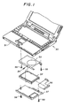
- FIG.1 is a disassembled perspective view of a notebook type
personal computer 50 mounted with a hard disk drive. In FIG.1, a hard disk drive (HDD) 52 is mounted in a HDD accommodating part provided on a back side of a front right of ahousing 51 of the notebook typepersonal computer 50. - In this case, The HDD 52 accommodates a disk-shaped storage media, a head, a motor and the like. The HDD 52 is fixed on a HDD mounting metal fitting 53 by a
screw 54 so that a printed circuit side of theHDD 52 faces aHDD cover 57. Themetal fitting 53 is fixed on thehousing 51 by ascrew 55. - In addition, a flexible printed circuit (FPC)
cable 56 mounted on thehousing 51 is arranged so as to electrically connect to the printed circuit of theHDD 52. Thereafter, theHDD cover 57 is slid to cover the HDD accommodating part of thehousing 51, and theHDD cover 57 is fixed to thehousing 51 byscrews 58. No shock absorbing material or the like is used. - In the case of a magnetic disk drive mounted in a lap-top computer or the like, it is proposed in a
Japanese Laid-Open Patent Application No.3-241583 - In addition, in the case of a fixed magnetic disk drive used in a large scale computer, it is proposed in a
Japanese Laid-Open Utility Model Application no.59-135504 - However, in the notebook type personal computer mounted with the HDD described above, the HDD itself is becoming smaller and lighter due to the increased recording density of the HDD. Particularly when the HDD is light, there are increased opportunities for the HDD to be carried. On the other hand, the mechanical strength of the HDD deteriorates as the HDD becomes smaller. As a result, a shock applied on the HDD while the HDD is carried or during operation of the HDD may generate a fault.
- For example, because the conventional HDD is fixed to the housing of the notebook type personal computer by screws, the magnetic head makes contact with the disk-shaped storage media when a shock is applied on the HDD which is carried or during operation of the HDD. The disk-shaped media is damaged when the magnetic head makes contact with the disk-shaped storage media, and this damage causes data destruction thereby generating a fault.
- On the other hand, if a floating structure is used for the HDD, it becomes impossible to accurately set a head position due to residual vibration accompanying the rotation of the disk-shaped storage media when making a seek operation to make the magnetic head seek a recording region during operation. In this case, a read error is generated.
- Further, in the case of the lap-top computer or the like, the vibration preventing rubber is provided on the side surface of the magnetic disk drive in order to make the magnetic disk drive vibration proof. However, no special considerations are made with respect to the shock, particularly the shock applied on the magnetic disk drive when the computer is carried. For this reason, the vibration preventing rubber does not provide a solution to the problems introduced when the magnetic disk drive is carried.
- Moreover, the portable fixed magnetic disk drive described above is not intended for the general user, and the fixed magnetic disk drive is considerably large compared to the HDD mounted in the notebook type personal computer. For this reason, there are no strict demands to reduce the size and weight of the fixed magnetic disk drive, and various kinds of measures may be taken against the vibration and shock applied on the fixed magnetic disk drive. However, such measures which may be taken in the fixed magnetic disk drive do not suggest particular measures which may be taken with respect to the notebook type personal computer which is used by the general user and in which restricting conditions exist to reduce the size and weight of the HDD.
- Accordingly, it is a general object of the present invention to provide a novel and useful electronic apparatus and a disk unit mounting mechanism, in which the problems described above are eliminated.
- Another and more specific object of the present invention is to eliminate the problem of data destruction caused by the shock applied on the disk unit such as the HDD, and to provide a disk unit mounting structure having an improved reliability.
- Still another object of the present invention is to provide an electronic apparatus mounted with a hard disk drive, wherein vibration and/or shock absorbing members which absorb vibration and/or shock are provided between the hard disk drive and a lid member which covers a hard disk drive accommodating part provided in a housing of the electronic apparatus. According to the present invention, it is possible to improve the vibration resistance and the shock resistance because the hard disk drive is protected by small pieces of the vibration and/or shock absorbing members. As a result, it is possible to prevent data destruction from being generated in the hard disk drive due to the shock and to prevent a read error from being generated in the hard disk drive due to the vibration. Accordingly, the reliability of the portable electronic apparatus such as the notebook type personal computer is greatly improved.
- A further object of the present invention is to provide an electronic apparatus mounted with a hard disk drive, comprising vibration and/or shock absorbing members which are formed by a plurality of small pieces and absorb vibration and/or shock are provided between the hard disk drive and a hard disk drive accommodating part provided in a housing of the electronic apparatus, and a sheet member is provided between the hard disk drive and the plurality of small pieces forming the vibration and/or shock absorbing members. According to the present invention, it is possible to improve the vibration resistance and the shock resistance because the hard disk drive is protected by small pieces of the vibration and/or shock absorbing members. As a result, it is possible to prevent data destruction from being generated in the hard disk drive due to the shock and to prevent a read error from being generated in the hard disk drive due to the vibration. Accordingly, the reliability of the portable electronic apparatus such as the notebook type personal computer is greatly improved. Further, it is possible to prevent direct contact with the vibration and/or shock absorbing members and the hard disk drive, so that the vibration and/or shock absorbing members will not be deformed at the time of the assembling process and moisture absorbed by the vibration and/or shock absorbing members will not cause an electrical short-circuit even if the vibration and/or shock absorbing members are provided on a side of the hard disk drive having exposed wirings and/or electrical circuits.
- Another object of the present invention is to provide an electronic apparatus mounted with a hard disk drive, wherein vibration and/or shock absorbing members are provided between the hard disk drive and an inner bottom surface and inner side surfaces of a hard disk drive accommodating part provided in a housing of the electronic apparatus, and the vibration and/or shock absorbing members provided between the hard disk drive and the inner bottom surface and the vibration and/or shock absorbing members provided between the hard disk drive and the inner surface are made of mutually different materials. According to the present invention, it is possible to improve the vibration resistance and the shock resistance because the hard disk drive is protected by small pieces of the vibration and/or shock absorbing members. As a result, it is possible to prevent data destruction from being generated in the hard disk drive due to the shock and to prevent a read error from being generated in the hard disk drive due to the vibration. Accordingly, the reliability of the portable electronic apparatus such as the notebook type personal computer is greatly improved.
- Another object of the present invention is to provide an electronic apparatus mounted with a hard disk drive, wherein a plurality of vibration and/or shock absorbing members made of different materials and having different thicknesses are provided with respect to at least one of confronting surfaces of the hard disk drive and a hard disk drive accommodating part provided in a housing of the electronic apparatus. According to the present invention, it is possible to improve the vibration resistance and the shock resistance because the hard disk drive is protected by small pieces of the vibration and/or shock absorbing members. As a result, it is possible to prevent data destruction from being generated in the hard disk drive due to the shock and to prevent a read error from being generated in the hard disk drive due to the vibration. Accordingly, the reliability of the portable electronic apparatus such as the notebook type personal computer is greatly improved.
- Still another object of the present invention is to provide a disk unit mounting mechanism mountable with a disk unit characterized by a disk unit accommodating part accommodating the disk unit which is mounted, a lid member covering the disk unit accommodating part, and a vibration and/or shock absorbing member which absorbs vibration and/or shock and is arranged between the lid member and the disk unit which is mounted. By providing the vibration and/or shock absorbing members between the disk unit which is mounted and the lid member which covers the disk unit accommodating part provided in the housing, it is possible to improve the shock-resistance of the disk unit. Hence, it is possible to prevent data destruction from being generated in the disk unit, such as the HDD, due to the shock when the disk unit is dropped or is placed on a desk.
- A further object of the present invention is to provide a disk unit mounting mechanism mountable with a disk unit characterized by a disk unit accommodating part accommodating the disk unit which is mounted, a lid member covering the disk unit accommodating part, and a vibration and/or shock absorbing member, formed by a plurality of small pieces and absorbs vibration and/or shock, arranged between the lid member and the disk unit which is mounted, and a sheet member arranged between the plurality of small pieces forming the vibration and/or shock absorbing member and the disk unit which is mounted. By mounting the vibration and/or shock absorbing members on the sheet material, it is possible to prevent the deformation of the vibration and/or shock absorbing members. As a result, the shock resistance of the disk unit is improved, and in addition, it is possible to prevent the electrical short-circuit even when the dew drop is formed on the vibration and/or shock absorbing members.
- Another object of the present invention is to provide a disk unit mounting mechanism mountable with a disk unit characterized by a disk unit accommodating part accommodating the disk unit which is mounted, and vibration and/or shock absorbing members arranged between an inner bottom surface and an inner side surface of the disk unit accommodating part and the disk unit which is mounted, wherein the vibration and/or
shock absorbing member 3 arranged between the disk unit which is mounted and the inner bottom surface and the vibration and/or shock absorbing member arranged between the disk unit which is mounted and the inner side surface are made of mutually different materials. By providing the vibration and/or shock absorbing members between the disk unit and the inner surface of the disk unit accommodating part provided in the housing, it is possible to improve the vibration resistance of the disk unit, thereby preventing a read error from being generated. Further, in this case, the vibration resistance is required of the vibration and/or shock absorbing members provided between the disk unit and the inner surface of the disk unit accommodating part provided in the housing, while the shock resistance is required of the vibration and/orshock absorbing members 3 provided between the disk unit and the inner bottom surface of the disk unit accommodating part. Hence, it is desirable that the vibration and/or shock absorbing members are made of mutually different materials. - Still another object of the present invention is to provide a disk unit mounting mechanism mountable with a disk unit characterized by a disk unit accommodating part accommodating the disk unit which is mounted, and vibration and/or shock absorbing members arranged between an inner bottom surface and an inner side surface of the disk unit accommodating part and the disk unit which is mounted, wherein the vibration and/or shock absorbing members arranged between the disk unit and the inner bottom surface and the vibration and/or shock absorbing member arranged between the disk unit and the inner side surface are made of materials having mutually different vibration and/or shock absorbing characteristics. By providing vibration and/or shock absorbing members having different vibration and/or shock absorbing characteristics, it is possible to effectively cope with shocks ranging from weak to strong shocks, and the vibration resistance and the shock resistance of the disk unit are improved.
- A further object of the present invention is to provide a disk unit mounting mechanism mountable with a disk unit characterized by a disk unit accommodating part accommodating the disk unit which is mounted, and a plurality of vibration and/or shock absorbing members having different thicknesses arranged with respect to at least one of confronting surfaces of the disk unit which is mounted and the disk unit accommodating part. By providing the vibration and/or shock absorbing members having the different thicknesses with respect to at least one surface of the disk unit, particularly with respect to a lid member, it is possible to use a thin material and a thick material, for example, so that the shock resistance is improved with respect to various kinds of shocks ranging from weak to strong shocks.
- Another object of the present invention is to provide a disk unit mounting mechanism mountable with a disk unit characterized by a disk unit accommodating part accommodating the disk unit which is mounted, and a plurality of vibration and/or shock absorbing members having different vibration and/or shock absorbing characteristics arranged with respect to at least one of confronting surfaces of the disk unit which is mounted and the disk unit accommodating part. By providing the vibration and/or shock absorbing members with respect to at least one surface of the disk unit, particularly, with respect to the side of a lid member, and forming the vibration and/or shock absorbing members from materials having different vibration and/or shock absorbing characteristics, it is possible to realize a shock resistance which can cope with a wide range of shocks ranging from weak to strong shocks.
- Other objects and further features of the present invention will be apparent from the following detailed description when read in conjunction with the accompanying drawings.
-
- FIG.1 is a disassembled perspective view showing an important part of a conventional notebook type personal computer;
- FIG.2 is a diagram for explaining the operating principle of the present invention;
- FIGS.3A and 3B respectively are perspective views showing a display panel part and a housing top cover of a first embodiment of an electronic apparatus according to the present invention;
- FIG.4 is a bottom view showing the housing top cover of the first embodiment of the electronic apparatus;
- FIG.5 is a disassembled perspective view showing a housing base of the first embodiment of the electronic apparatus;
- FIG.6 is a perspective view showing a mounting structure of vibration and/or shock absorbing members on the housing base of the first embodiment of the electronic apparatus;
- FIGS.7A through 7C respectively are diagrams showing an important part of a second embodiment of the electronic apparatus;
- FIGS.8A through 8C respectively are diagrams showing an important part of a first modification of the second embodiment of the electronic apparatus;
- FIG.9 is a perspective view showing an important part of a second modification of the second embodiment of the electronic apparatus; and
- FIG.10 is a perspective view showing a third embodiment of the electronic apparatus according to the present invention.
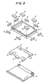
- FIG.2 is a diagram for explaining the operating principle of the present invention. A description will be given of means for solving the problems in the present invention, by referring to FIG.2.
- FIG.2 is a disassembled perspective view generally showing a HDD (hard disk drive) mounting structure, and the illustration of a housing is omitted. Although the following description takes the HDD as an example of the disk unit, the application of the present invention is of course not limited to the HDD, and the present invention is similarly applicable to various kinds of disk units such as a FDD (floppy disk drive).
- (1) An electronic apparatus mounted with a disk unit 1 in the present invention is characterized in that vibration and/or
shock absorbing members 3 which absorb vibration and/or shock are provided between the disk unit 1 and alid member 2 which covers a disk unit accommodating part provided in a housing of the electronic apparatus.
By providing the vibration and/orshock absorbing members 3 between the disk unit 1 and thelid member 2 which covers the disk unit accommodating part provided in the housing, it is possible to improve the shock-resistance of the electronic apparatus. Hence, it is possible to prevent data destruction from being generated in the disk unit 1, such as the HDD, due to the shock when the electronic apparatus is dropped or is placed on a desk. - (2) The present invention is characterized in that, in (1) above, the vibration and/or
shock absorbing members 3 provided between thelid member 2 and the disk unit 1 are formed by a plurality of small pieces.
A single large vibration and/or shock absorbing member may be provided on the entire surface as the vibration and/orshock absorbing member 3. But by forming the vibration and/orshock absorbing members 3 from the plurality of small pieces, it is possible to further improve the vibration resistance and the shock resistance. - (3) The present invention is characterized in that, in (2) above, a sheet member 6 is provided between the disk unit 1 and the plurality of small pieces forming the vibration and/or
shock absorbing members 3.
In general, the vibration and/orshock absorbing members 3 are made of a porous material having a large coefficient of friction. For this reason, if thelid member 2 were mounted by sliding thelid member 2, the vibration and/orshock absorbing members 3 would be deformed in a horizontal direction due to the friction and the vibration and/or shock absorbing effect would be reduced. But by mounting the vibration and/orshock absorbing members 3 on the sheet material 6, it is possible to prevent the deformation of the vibration and/orshock absorbing members 3.
In addition, when dew drop is formed on the vibration and/orshock absorbing members 3 which are provided between thelid member 2 and the disk unit 1, the moist vibration and/orshock absorbing members 3 will make contact with the printed circuit of the disk unit 1 because the vibration and/or shock absorbing member 3s uneasily dry, thereby causing an electrical short-circuit. But by interposing the sheet member 6 between the disk unit 1 and the vibration and/orshock absorbing members 3, it is possible to prevent the electrical short-circuit even when the dew drop is formed on the vibration and/orshock absorbing members 3. - (4) An electronic apparatus mounted with a disk unit 1 in the present invention is characterized in that vibration and/or
shock absorbing members 3 which are formed by a plurality of small pieces and absorb vibration and/or shock are provided between the disk unit 1 and alid member 2 which covers a disk unit accommodating part provided in a housing of the electronic apparatus, and a sheet member 6 is provided between the disk unit 1 and the plurality of small pieces forming the vibration and/orshock absorbing members 3.
As described above under (3) above, by mounting the vibration and/orshock absorbing members 3 on the sheet material 6, it is possible to prevent the deformation of the vibration and/orshock absorbing members 3. As a result, the shock resistance of the electronic apparatus is improved, and in addition, it is possible to prevent the electrical short-circuit even when the dew drop is formed on the vibration and/orshock absorbing members 3. - (5) An electronic apparatus mounted with a disk unit 1 in the present invention is characterized in that vibration and/or
shock absorbing members shock absorbing members 3 provided between the disk unit 1 and the inner bottom surface and the vibration and/orshock absorbing members 4 provided between the disk unit 1 and the inner surface are made of mutually different materials.
By providing the vibration and/orshock absorbing members 4 between the disk unit 1 and the inner surface of the disk unit accommodating part provided in the housing, it is possible to improve the vibration resistance of the disk unit 1, thereby preventing a read error from being generated.
Further, in this case, the vibration resistance is required of the vibration and/orshock absorbing members 4 provided between the disk unit 1 and the inner surface of the disk unit accommodating part provided in the housing, while the shock resistance is required of the vibration and/orshock absorbing members 3 provided between the disk unit 1 and the inner bottom surface of the disk unit accommodating part. Hence, it is desirable that the vibration and/orshock absorbing members - (6) An electronic apparatus mounted with a disk unit 1 in the present invention is characterized in that vibration and/or
shock absorbing members shock absorbing members shock absorbing member 4 provided between the disk unit 1 and the inner side surface are made of materials having mutually different vibration and/or shock absorbing characteristics.
By providing vibration and/or shock absorbing members having different vibration and/or shock absorbing characteristics, it is possible to effectively cope with shocks ranging from weak to strong shocks, and the vibration resistance and the shock resistance of the electronic apparatus are improved. - (7) The present invention is characterized in that, in (5) or (6) above, the vibration and/or
shock absorbing member 4 provided between the disk unit 1 and the inner side surface is made of a material having a higher vibration resistance than a material forming the vibration and/orshock absorbing members
In this case, it is possible to flexibly cope with the vibration resistance and the shock resistance required by the electronic apparatus. - (8) The present invention is characterized in that, in (5) or (6) above, the vibration and/or
shock absorbing member 4 provided between the disk unit 1 and the inner side surface is made of a material which is harder than a material forming the vibration and/orshock absorbing members
In this case, it is possible to flexibly cope with the vibration resistance and the shock resistance required by the electronic apparatus. - (9) The present invention is characterized in that, in any of (5) to (8) above, the vibration and/or
shock absorbing members 4 provided between the disk unit 1 and the inner surface of the disk unit accommodating part provided in the housing are formed by a plurality of small pieces.
A single large vibration and/or shock absorbing member may be provided on the entire surface as the vibration and/orshock absorbing member 4 which is provided between the disk unit 1 and the inner surface of the disk unit accommodating part provided in the housing. But by forming the vibration and/orshock absorbing members 4 from the plurality of small pieces, it is possible to further improve the vibration resistance. - (10) An electronic apparatus mounted with a disk unit 1 in the present invention is characterized in that a plurality of vibration and/or
shock absorbing members
By providing the vibration and/orshock absorbing members lid member 2, it is possible to use a thin material and a thick material, for example, so that the shock resistance is improved with respect to various kinds of shocks ranging from weak to strong shocks. - (11) The present invention is characterized in that, in (10) above, the plurality of vibration and/or
shock absorbing members
In this case, it is possible to flexibly cope with the vibration resistance and the shock resistance required by the electronic apparatus. - (12) An electronic apparatus mounted with a disk unit 1 in the present invention is characterized in that a plurality of vibration and/or
shock absorbing members
By providing the vibration and/orshock absorbing members lid member 2, and forming the vibration and/orshock absorbing members - (13) The present invention is characterized in that in (10) or (12) above, the plurality of vibration and/or
shock absorbing members
In this case, it is possible to flexibly cope with the vibration resistance and the shock resistance required by the electronic apparatus. - (14) The present invention is characterized in that, in any of (1) to (13) above, the vibration and/or
shock absorbing members 5 are also provided between the disk unit 1 and an inner top surface of the disk unit accommodating part provided in the housing.
By providing the vibration and/orshock absorbing members 5 between the disk unit 1 and the inner top surface of the disk unit accommodating part provided in the housing, it is possible to further improve the vibration resistance and the shock resistance, and particularly the shock resistance. - (15) The present invention is characterized in that, in any of (1) to (14) above, the vibration and/or
shock absorbing members
From the point of view of the problems introduced by the dew drop and the ease of the assembling process, it is desirable to adhere the vibration and/orshock absorbing members lid member 2 or, on the inner top surface or the inner side surface of the disk unit accommodating part provided in the housing. - (16) The present invention is characterized in that, in any of (1) to (15) above, the electronic apparatus mounted with the disk unit 1 forms a portable electronic apparatus.
By applying the structure of the present invention to the portable electronic apparatus, it is possible to improve the reliability of the portable electronic apparatus with respect to the shock applied thereto when the portable electronic apparatus is carried. - (17) The present invention is characterized in that, in any of (1) to (16) above, the disk unit 1 is a hard disk unit.
In this case, it is possible to improve the reliability of the hard disk unit. - (18) A disk unit mounting mechanism mountable with a disk unit 1 in the present invention is characterized by a disk unit accommodating part accommodating the disk unit 1 which is mounted, a
lid member 2 covering the disk unit accommodating part, and a vibration and/orshock absorbing member 3 which absorbs vibration and/or shock and is arranged between thelid member 2 and the disk unit 1 which is mounted.
By providing the vibration and/orshock absorbing members 3 between the disk unit 1 which is mounted and thelid member 2 which covers the disk unit accommodating part provided in the housing, it is possible to improve the shock-resistance of the disk unit. Hence, it is possible to prevent data destruction from being generated in the disk unit 1, such as the HDD, due to the shock when the disk unit is dropped or is placed on a desk. - (19) A disk unit mounting mechanism mountable with a disk unit 1 in the present invention is characterized by a disk unit accommodating part accommodating the disk unit 1 which is mounted, a
lid member 2 covering the disk unit accommodating part, and a vibration and/orshock absorbing member 3, formed by a plurality of small pieces and absorbs vibration and/or shock, arranged between the lid member and the disk unit which is mounted, and a sheet member 6 arranged between the plurality of small pieces forming the vibration and/orshock absorbing member 3 and the disk unit 1 which is mounted.
As described above under (3) above, by mounting the vibration and/orshock absorbing members 3 on the sheet material 6, it is possible to prevent the deformation of the vibration and/orshock absorbing members 3. As a result, the shock resistance of the disk unit is improved, and in addition, it is possible to prevent the electrical short-circuit even when the dew drop is formed on the vibration and/or shock absorbing members'3. - (20) A disk unit mounting mechanism mountable with a disk unit 1 in the present invention is characterized by a disk unit accommodating part accommodating the disk unit 1 which is mounted, and vibration and/or
shock absorbing members shock absorbing member 3 arranged between the disk unit 1 which is mounted and the inner bottom surface and the vibration and/orshock absorbing member 4 arranged between the disk unit 1 which is mounted and the inner side surface are made of mutually different materials.
By providing the vibration and/orshock absorbing members 4 between the disk unit 1 and the inner surface of the disk unit accommodating part provided in the housing, it is possible to improve the vibration resistance of the disk unit 1, thereby preventing a read error from being generated.
Further, in this case, the vibration resistance is required of the vibration and/orshock absorbing members 4 provided between the disk unit 1 and the inner surface of the disk unit accommodating part provided in the housing, while the shock resistance is required of the vibration and/orshock absorbing members 3 provided between the disk unit 1 and the inner bottom surface of the disk unit accommodating part. Hence, it is desirable that the vibration and/orshock absorbing members - (21) A disk unit mounting mechanism mountable with a disk unit 1 in the present invention is characterized by a disk unit accommodating part accommodating the disk unit 1 which is mounted, and vibration and/or
shock absorbing members shock absorbing members shock absorbing member 4 arranged between the disk unit 1 and the inner side surface are made of materials having mutually different vibration and/or shock absorbing characteristics.
By providing vibration and/or shock absorbing members having different vibration and/or shock absorbing characteristics, it is possible to effectively cope with shocks ranging from weak to strong shocks, and the vibration resistance and the shock resistance of the disk unit are improved. - (22) A disk unit mounting mechanism mountable with a disk unit 1 in the present invention is characterized by a disk unit accommodating part accommodating the disk unit 1 which is mounted, and a plurality of vibration and/or
shock absorbing members
By providing the vibration and/orshock absorbing members lid member 2, it is possible to use a thin material and a thick material, for example, so that the shock resistance is improved with respect to various kinds of shocks ranging from weak to strong shocks. - (23) A disk unit mounting mechanism mountable with a disk unit 1 in the present invention is characterized by a disk unit accommodating part accommodating the disk unit 1 which is mounted, and a plurality of vibration and/or
shock absorbing members - By providing the vibration and/or
shock absorbing members lid member 2, and forming the vibration and/orshock absorbing members - Next, a description will be given of a first embodiment of the present invention, by referring to FIGS.3 through 6.
- In order to simplify the description, the illustration and description of mounting structures of small parts which are not directly related to the subject matter of the present invention are omitted.
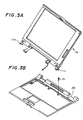
- FIG.3A is a perspective view showing a
display panel part 10 of a notebook type personal computer. Mounting metal fittings 111 and 112 provided on both sides at a lower end of thedisplay panel part 10 are positioned with respect to recesses of aplastic housing base 30 shown in FIG.5, and are fixed to thehousing base 30 byscrews - FIG.3B is a perspective view showing a housing top cover 20 made of a plastic. The
housing top cover 20 is positioned with respect to thehousing base 30 shown in FIG.5, and is fixed to thehousing base 30 byscrews - The
screws 32 fix the housing top cover 20 on thehousing base 30 via the mounting metal fittings 111 and 112. - FIG.4 is a bottom view showing a back side of the housing top cover 20 shown in FIG.3B. 2 small pieces of vibration and/or
shock absorbing members HDD 34, that is, on an innertop surface 22 of aHDD accommodating part 35. - For example, the vibration and/or
shock absorbing members - FIG.5 is a disassembled perspective view of the
housing base 30 showing a mounting structure of theHDD 34. After accommodating theHDD 34 in theHDD accommodating part 35, aplastic lid member 40 is mounted at an opening of theHDD accommodating part 35 by sliding thelid member 40, and thelid member 40 is fixed on thehousing base 30 byscrews 44. Thelid member 40 is provided with asheet material 41 which is made of a polyester film. 3 small pieces of vibration and/or shock absorbing members 421, 422 and 423 are adhered along one of the 2 longer sides of thesheet material sheet material 41. - In FIG.5, a connector with respect to a
FPC cable 36 is indicated by broken lines on the left of theHDD 34. - Similarly to the vibration and/or
shock absorbing members - When the 6 vibration and/or shock absorbing members 421, 422, 423, 431, 432 and 433 made of the ether system polyurethane are provided, it was confirmed as a result of experiments conducted with regard to the shock resistance that, with respect to a shock which causes a maximum acceleration speed of 185.25 G in the case of the conventional HDD fixed by the screws, the maximum acceleration speed becomes 117.00 G in the case of the
HDD 34 mounted with the mounting structure of this embodiment. Hence, the shock resistance of the HDD in this embodiment was greatly improved compared to the conventional HDD fixed by the screws. - The vibration and/or
shock absorbing members HDD accommodating part 35 are arranged so as not to overlap theFPC cable 36 in a projection. Hence, theHDD 34 makes direct contact with the vibration and/orshock absorbing members HDD 34 is protected from the vibration and/or shock by the vibration and/orshock absorbing members HDD 34. - In addition, the
sheet material 41 is provided so that theHDD 34 will not make direct contact with the vibration and/or shock absorbing members 421, 422, 423, 431, 432 and 433 which have a large coefficient of friction, when sliding thelid member 40 and mounting thelid member 40 at the opening of theHDD accommodating part 35. Thus, by using thissheet material 41, the vibration and/or shock absorbing members 421, 422, 423, 431, 432 and 433 will not be deformed in the horizontal direction due to the friction when thelid member 40 is slid, thereby making it possible to obtain the designed vibration resistance and shock resistance. Further, moisture absorbed by the vibration and/or shock absorbing members 421, 422, 423, 431, 432 and 433 will not cause an electrical short-circuit even if the vibration and/or shock absorbing members 421, 422, 423, 431, 432 and 433 are provided on a side of theHDD 34 having exposed wirings and/or electrical circuits. - FIG.6 is a perspective view of the
housing base 30 showing the arrangement of vibration and/or shock absorbing members 371 through 378 provided on the inner side surfaces of theHDD accommodating part 35. In FIG.6, the illustration of the mounting state of some of the small parts shown in FIG.5 is omitted. - As shown in FIG.6, 2 small pieces of the vibration and/or shock absorbing members 371 through 368 are adhered on each of the 4 inner side surfaces of the
HDD accommodating part 35. - In this case, a high vibration resistance is required of the vibration and/or shock absorbing members 371 through 378, and thus, the vibration and/or shock absorbing members 371 through 378 must be made of a hard material compared to the vibration and/or
shock absorbing member 231 or the like. For example, a high-density urethane foam material having a thickness of 3 mm, a density of 0.48 g/cm3, a tensile strength of 18.0 kg/cm2, an elongation of 140%, a tear strength of 6.3 kg/cm, a compression strength of 2.5 kg/cm2 to compress 25%, and a compression residual distortion of 3.9%. - By providing the vibration and/or shock absorbing members 371 through 378 on the inner side surfaces of the
HDD accommodating part 35, the vibration resistance of theHDD 34 is improved. In addition, it is possible to prevent a read error from being generated due to residual vibration accompanying the rotation of the disk-shaped storage media when making a seek operation in theHDD 34. - As described above, in the first embodiment of the present invention, the small pieces of vibration and/or
shock absorbing members 231 through 233, 421 through 433 and 371 through 378 are provided on the inner top and bottom surfaces and the 4 inner side surfaces, that is, a total of six surfaces, of theHDD accommodating part 35 making contact with theHDD 34. For this reason, it is possible to effectively protect theHDD 34 from the shock which is applied on the HDD when the notebook type personal computer is dropped or when the notebook type personal computer is placed on the desk, for example. As a result, the disk-shaped storage media is undamaged, and the reliability of theHDD 34 is improved because the fault caused by data destruction is prevented. - The reason why the vibration and/or shock absorbing member is divided into small pieces is because, as a result of various kinds of experiments which were conducted, it was found that the vibration resistance and the shock resistance are improved when small pieces of the vibration and/or shock absorbing members are used as compared to the case where a single large vibration and/or shock absorbing member is used.
- In addition, since the
sheet material 41 is used in this first embodiment, a short-circuit will not be generated by the vibration and/or shock absorbing members 421 through 433 which confront the printed circuit of theHDD 34, even when the dew drop is formed on the vibration and/or shock absorbing members 421 through 433. Hence, the reliability of theHDD 34 is improved. - In the first embodiment described above, a polyester film is used as the
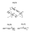
sheet material 41. However, the material used for thesheet material 41 is not limited to polyester, and any insulator material having a small coefficient of friction, such as a teflon resin sheet material, may be used as thesheet material 41. - Next, a description will be given of a second embodiment of the present invention, by referring to FIGS.7A through 7C. In this second embodiment, the structure of the vibration and/or shock absorbing material provided on the
lid member 40 is different from that of the first embodiment, but the second embodiment is otherwise the same as the first embodiment. FIG.7A is a perspective view showing an important part of the second embodiment, FIG.7B is a side view viewed in a direction A in FIG. 7A, and FIG.7C is a side view viewed in a direction B in FIG.7A. - In this second embodiment, on a side of the
sheet material 41 confronting thelid member shock absorbing members 411 are adhered along one of the 2 longer sides of thesheet material shock absorbing members 412 are adhered along the other of the 2 longer sides of thesheet material 41, similarly to the first embodiment. Thesheet material 41 is made of a polyester film, and the vibration and/orshock absorbing members 411 have a thickness of 2 mm and are made of a soft ether system polyurethane. In addition, vibration and/orshock absorbing members 412 having a thickness of 1.5 mm and made of an ether system polyurethane (Sorbothane, trademark) which is harder than the vibration and/orshock absorbing members 411 are additionally provided between each of the vibration and/orshock absorbing members 411. - It is desirable that the thickness of the vibration and/or
shock absorbing members 412 which are additionally provided is set approximately equal to a thickness at which the compressed vibration and/orshock absorbing members 411 lose the buffering effect. If the case of a weak shock, the shock is softly absorbed solely by the soft vibration and/orshock absorbing members 411. On the other hand, in the case of a strong shock, the shock is absorbed in 2 stages, that is, the soft vibration and/orshock absorbing members 411, and the hard vibration and/orshock absorbing members 412 which are additionally provided to absorb the shock which cannot be fully absorbed by the soft vibration and/orshock absorbing members 411. Therefore, as compared to the first embodiment, this second embodiment can more effectively cope with various kinds of shocks ranging from weak to strong shocks. - Next, a description will be given of a first modification of the second embodiment, by referring to FIGS.8A through 8C. FIG.8A is a perspective view showing an important part of the first modification of the second embodiment, FIG.8B is a side view viewed in a direction A in FIG.8A, and FIG.8C is a side view viewed in a direction B in FIG.8A.
- In this second embodiment, the 2-stage structure, made up of the soft vibration and/or
shock absorbing members 411 and the hard vibration and/orshock absorbing members 412, is provided with respect to thelid member 40. However, the vibration and/orshock absorbing members 412 which are additionally provided are not limited to the material which is harder than the soft vibration and/orshock absorbing members 411. It is possible to realize the 2-stage structure by use of the same material (or the same hardness) but by varying the thicknesses of vibration and/orshock absorbing members 421 and vibration and/orshock absorbing members 422 which are additionally provided, as shown in FIGS.8A through 8C. Alternatively, it is possible to realize the 2-state structure by using materials having mutually different vibration and/or shock absorbing characteristics for the vibration and/orshock absorbing members 421 and the vibration and/orshock absorbing members 422 which are additionally provided. - Next, a description will be given of a second modification of the second embodiment, by referring to FIG.9. FIG.9 is a perspective view showing an important part of the second modification of the second embodiment.
- In this second modification of the second embodiment, relative hardnesses of vibration and/or
shock absorbing members shock absorbing members 431 is greater than that of the vibration and/orshock absorbing members 432, or vice versa. - Furthermore, the vibration and/or
shock absorbing members 231 through 233 provided on the innertop surface 22 of theHDD accommodating part 35 may also have the 2-stage structure described above. Moreover, the vibration and/or shock absorbing members 371 through 378 provided on the inner side surfaces of theHDD accommodating part 35 may also have the 2-stage structure described above. By using the 2-stage structure, the number of parts increases, but the vibration resistance and the shock resistance are further improved. - Next, a description will be given of a third embodiment of the present invention, by referring to FIG.10.
- In this third embodiment, the structure of the vibration and/or shock absorbing material provided on the
lid member 40 is different from that of the first embodiment, but this third embodiment is otherwise the same as the first embodiment. Accordingly, a description will only be given with respect to the structure of thelid member 40. - In this third embodiment, a pair of elongated vibration and/or shock absorbing members 451 and 452 having a thickness of 2 mm and made of a soft ether system polyurethane (Sorbothane, trademark) is adhered directly on the
plastic lid member 40 on the surface of thelid member 40 confronting theHDD 34, along the 2 longer sides of thelid member 40. - It was confirmed as a result of experiments conducted with regard to the shock resistance that, with respect to a shock which causes a maximum acceleration speed of 185.25 G in the case of the conventional HDD fixed by the screws, the maximum acceleration speed becomes 139.19 G in the case of the
HDD 34 mounted with the mounting structure of this embodiment. Hence, the shock resistance of the HDD in this embodiment was improved compared to the conventional HDD fixed by the screws. - The shock resistance obtained in this third embodiment is not as high as that obtained in the first embodiment. However, this third embodiment has an advantage over the first embodiment in that the number of vibration and/or shock absorbing members is small, and the operation of adhering the vibration and/or shock absorbing members can be simplified due to the small number of vibration and/or shock absorbing members.
- In this third embodiment, the vibration and/or shock absorbing members 451 and 452 are adhered directly on the
lid member 40. However, it is of course possible to adhere the vibration and/or shock absorbing members 451 and 452 via a polyethylene sheet material, similarly to the first embodiment described above. - Although the present invention is applied to the HDD in the embodiments described above, the application of the present invention is of course not limited to the HDD. The present invention is similarly applicable to various kinds of disk units, including floppy disk drives, compact disk units, DVD (digital video disk) units, MD (magnetic disk) units, and MO (magneto-optic) disk units.
- For example, the soft vibration and/or shock absorbing members provided above and below the HDD accommodating part are not limited to the soft ether system polyurethane, and appropriate modifications may be made depending on the design specifications of the computer. In addition, the thickness of the vibration and/or shock absorbing members is of course not limited to 2 mm, and the thickness may be varied arbitrarily depending on the characteristic of the vibration and/or shock absorbing material used.
- If the vibration and/or shock absorbing members are too soft or too thin, the shock resistance deteriorates. Hence, it is necessary to select the material and thickness of the vibration and/or shock absorbing members within a range such that the space occupied by the vibration and/or shock absorbing members within the HDD accommodating part will not increase considerably, so as to satisfy the design specifications, that is, guarantee a shock resistance of 300 G when the HDD is not in use, for example.
- On the other hand, the vibration and/or shock absorbing members provided on the inner side surfaces of the HDD accommodating part are not limited to the high-density urethane foam having the characteristic of the above described embodiment. The thickness of these vibration and/or shock absorbing members is likewise not limited to 3 mm, and appropriate modifications may be made depending on the design specifications.
- In addition, the present invention is applied to the notebook type personal computer in the embodiments described above. However, the application of the present invention is not limited to the notebook type personal computer, and the present invention is applicable to any portable electronic apparatus in general which is mounted with a disk unit such as a HDD, such as a notebook type word processor and a pen input type personal computer.
- Therefore, according to the present invention, it is possible to improve the vibration resistance and the shock resistance because the disk unit such as the HDD is protected by small pieces of the vibration and/or shock absorbing members. As a result, it is possible to prevent data destruction from being generated in the disk unit due to the shock and to prevent a read error from being generated in the HDD due to the vibration. Accordingly, the reliability of the portable electronic apparatus such as the notebook type personal computer is greatly improved.
- Moreover, the present invention is applicable to any kind of electronic apparatus mounted with or is designed to be mounted with a disk unit. Hence, the present invention is similarly applicable to a docking station or an extended peripheral unit which is connected to a portable information processing apparatus such as a notebook type computer, and is mounted with or is designed to be mounted with a disk unit.
- Further, the present invention is not limited to these embodiments, but various variations and modifications may be made without departing from the scope of the present invention.
Claims (8)
- An electronic apparatus mounted with a disk unit, characterized in that a vibration and/or shock absorbing member which is formed by a plurality of small pieces and absorbs vibration and/or shock is provided between the disk unit and a lid member which covers a disk unit accommodating part provided in a housing of the electronic apparatus; and a sheet member is provided between the disk unit and the plurality of small pieces forming the vibration and/or shock absorbing member.
- An electronic apparatus as claimed in claim 1, wherein the vibration and/or shock absorbing member is provided between the disk unit and an inner bottom surface and an inner side surface of a disk unit accommodating part provided in a housing of the electronic apparatus, and wherein the vibration and/or shock absorbing member is provided between the disk unit and the inner bottom surface and the vibration and/or shock absorbing member provided between the disk unit and the inner side surface are made of mutually different materials.
- An electronic apparatus as claimed in claim 1, wherein the vibration and/or shock absorbing member is provided between the disk unit and an inner bottom surface and an inner side surface of a disk unit accommodating part provided in a housing of the electronic apparatus, and wherein the vibration and/or shock absorbing member is provided between the disk unit and the inner bottom surface, and wherein the vibration and/or shock absorbing member provided between the disk unit and the inner side surface are made of materials having mutually different vibration and/or shock absorbing characteristics.
- An electronic apparatus as claimed in claim 2 or 3, characterised in that the vibration and/or shock absorbing member provided between the disk unit and the inner side surface is made of a material having a higher vibration resistance than a material forming the vibration and/or shock absorbing member provided between the disk unit and the inner bottom surface.
- An electronic apparatus as claimed in claim 2 or 3, characterized in that the vibration and/or shock absorbing member provided between the disk unit and the inner side surface is made of a material which is harder than a material forming the vibration and/or shock absorbing member provided between the disk unit and the inner bottom surface.
- An electronic apparatus as claimed in any of claims 2 to 5, characterized in that the vibration and/or shock absorbing member provided between the disk unit and the inner side surface of the disk unit accommodating part provided in the housing is formed by a plurality of small pieces.
- A disk unit mounting mechanism mountable with a disk unit, characterized by a disk unit accommodating part for accommodating the disk unit which is mounted; a lid member covering the disk unit accommodating part; and a vibration and/or shock absorbing member, formed by a plurality of small pieces for absorbing vibration and/or shock, the vibration and/or shock absorbing member being arranged between the lid member and the disk unit which is mounted; and a sheet member arranged between the plurality of small pieces forming the vibration and/or shock absorbing member and the disk unit which is mounted.
- A disk unit mounting mechanism as claimed in claim 7, wherein the vibration and/or shock absorbing member is arranged between an inner bottom surface and an inner side surface of the disk unit accommodating part and the disk unit which is mounted, the vibration and/or shock absorbing member arranged between the disk unit and the inner bottom surface and the vibration and/or shock absorbing member arranged between the disk unit and the inner side surface being made of materials having mutually different vibration and/or shock absorbing characteristics.
Applications Claiming Priority (3)
| Application Number | Priority Date | Filing Date | Title |
|---|---|---|---|
| JP30464097 | 1997-11-06 | ||
| JP30708598A JP4105309B2 (en) | 1997-11-06 | 1998-10-28 | Electronic device and mounting mechanism |
| EP98309019A EP0917036B1 (en) | 1997-11-06 | 1998-11-04 | Electronic apparatus with disk unit mounting mechanism |
Related Parent Applications (2)
| Application Number | Title | Priority Date | Filing Date |
|---|---|---|---|
| EP98309019.2 Division | 1998-11-04 | ||
| EP98309019A Division EP0917036B1 (en) | 1997-11-06 | 1998-11-04 | Electronic apparatus with disk unit mounting mechanism |
Publications (3)
| Publication Number | Publication Date |
|---|---|
| EP1731988A2 true EP1731988A2 (en) | 2006-12-13 |
| EP1731988A3 EP1731988A3 (en) | 2011-06-08 |
| EP1731988B1 EP1731988B1 (en) | 2014-08-27 |
Family
ID=26563987
Family Applications (2)
| Application Number | Title | Priority Date | Filing Date |
|---|---|---|---|
| EP98309019A Expired - Lifetime EP0917036B1 (en) | 1997-11-06 | 1998-11-04 | Electronic apparatus with disk unit mounting mechanism |
| EP06019055.0A Expired - Lifetime EP1731988B1 (en) | 1997-11-06 | 1998-11-04 | Disk unit mounting mechanism |
Family Applications Before (1)
| Application Number | Title | Priority Date | Filing Date |
|---|---|---|---|
| EP98309019A Expired - Lifetime EP0917036B1 (en) | 1997-11-06 | 1998-11-04 | Electronic apparatus with disk unit mounting mechanism |
Country Status (4)
| Country | Link |
|---|---|
| US (1) | US6751092B1 (en) |
| EP (2) | EP0917036B1 (en) |
| JP (1) | JP4105309B2 (en) |
| DE (1) | DE69836892T2 (en) |
Cited By (2)
| Publication number | Priority date | Publication date | Assignee | Title |
|---|---|---|---|---|
| EP1947650A2 (en) * | 2007-01-17 | 2008-07-23 | Advanced Digital Broadcast S.A. | Device with support structure for hard disk drive and method for mounting hard disk drive |
| CN101271355B (en) * | 2007-03-19 | 2011-02-09 | 株式会社东芝 | Electronic equipment and personal computer |
Families Citing this family (51)
| Publication number | Priority date | Publication date | Assignee | Title |
|---|---|---|---|---|
| US6735043B2 (en) | 1999-05-07 | 2004-05-11 | Seagate Technology Llc | Disc drive protective cover to improve shock robustness |
| JP3792474B2 (en) | 2000-03-30 | 2006-07-05 | 富士通株式会社 | Shock absorber for electronic device built-in parts |
| JP4608782B2 (en) * | 2001-01-23 | 2011-01-12 | パナソニック株式会社 | Information processing device |
| WO2002082430A2 (en) * | 2001-04-06 | 2002-10-17 | Seagate Technology Llc | Disc drive protective cover to improve shock robustness |
| JP3617973B2 (en) * | 2002-01-15 | 2005-02-09 | 株式会社東芝 | Information equipment |
| US20030179543A1 (en) * | 2002-03-25 | 2003-09-25 | International Business Machines Corporation | Deformable shock absorbing mechanism for a computer apparatus or a precision apparatus |
| KR100840941B1 (en) | 2002-12-11 | 2008-06-24 | 삼성전자주식회사 | Hard disk drive and Portable Computer having the same |
| ATE349058T1 (en) | 2003-03-31 | 2007-01-15 | Matsushita Electric Ind Co Ltd | SHOCK ABSORBING ELEMENT, SHOCK ABSORBING METHOD FOR AN ELECTRONIC DEVICE USING THIS ELEMENT, AND ELECTRONIC DEVICE ADAPTED FOR THIS ELEMENT AND THIS METHOD |
| JP2005173509A (en) * | 2003-12-15 | 2005-06-30 | Fujitsu Ltd | Electronic apparatus |
| US7251131B2 (en) * | 2004-07-15 | 2007-07-31 | Olixir Technologies | Ruggedized host module |
| JP4385327B2 (en) * | 2004-07-30 | 2009-12-16 | 日本ビクター株式会社 | Information processing device |
| JP4094000B2 (en) * | 2004-10-07 | 2008-06-04 | エフシーアイ アジア テクノロジー ピーティーイー リミテッド | connector |
| US20060120031A1 (en) * | 2004-12-06 | 2006-06-08 | Matsushita Electric Industrial Co., Ltd. | System for improved shock resistance for hard drives |
| JP4909510B2 (en) * | 2004-12-20 | 2012-04-04 | 株式会社東芝 | Electronics |
| JP2006277510A (en) * | 2005-03-30 | 2006-10-12 | Toshiba Corp | Portable information apparatus |
| JP4915117B2 (en) * | 2005-04-20 | 2012-04-11 | ソニー株式会社 | Vibration shock absorbing mechanism and content reproduction apparatus |
| US20060259918A1 (en) * | 2005-05-16 | 2006-11-16 | Dell Products L.P. | Method and apparatus for mounting a storage device in an information handling system |
| JP4603424B2 (en) * | 2005-06-08 | 2010-12-22 | 北川工業株式会社 | Shock absorbing spacer |
| JP2007085533A (en) * | 2005-09-21 | 2007-04-05 | Protect:Kk | Vibration absorption plate for vibrating equipment |
| JP2007294043A (en) | 2006-04-26 | 2007-11-08 | Toshiba Corp | Electronic device and disk drive device |
| JP4745117B2 (en) * | 2006-04-28 | 2011-08-10 | 株式会社東芝 | TV with built-in hard disk |
| JP2007095079A (en) * | 2006-10-02 | 2007-04-12 | Fujitsu Ltd | Electronic apparatus and built-in unit cushioning member for electronic apparatus |
| DE602007006142D1 (en) | 2006-12-28 | 2010-06-10 | Panasonic Corp | Buffer element, shock-absorbing device for a hard disk drive and mobile information device with it |
| US7684183B2 (en) * | 2007-03-29 | 2010-03-23 | Panasonic Corporation | Impact buffer, impact buffering device, and information processor having impact buffering device |
| JP4847414B2 (en) * | 2007-08-09 | 2011-12-28 | 富士通株式会社 | Electronic component mounting parts and electronic equipment |
| JP4833939B2 (en) * | 2007-08-13 | 2011-12-07 | 富士通株式会社 | Electronics |
| US7701705B1 (en) | 2007-12-10 | 2010-04-20 | Western Digital Technologies, Inc. | Information storage device with sheet metal projections and elastomeric inserts |
| US8164849B1 (en) | 2007-12-10 | 2012-04-24 | Western Digital Technologies, Inc. | Information storage device with a conductive shield having free and forced heat convection configurations |
| DE102008063113A1 (en) * | 2008-01-09 | 2009-07-16 | Marquardt Gmbh | power tool |
| US7626812B2 (en) * | 2008-01-31 | 2009-12-01 | Sercomm Corporation | Removable hard-disk structure without screws |
| US8004791B2 (en) * | 2008-02-22 | 2011-08-23 | Western Digital Technologies, Inc. | Information storage device with a bridge controller and a plurality of electrically coupled conductive shields |
| US8390952B1 (en) | 2008-02-22 | 2013-03-05 | Western Digital Technologies, Inc. | Information storage device having a conductive shield with a peripheral capacitive flange |
| US8697970B2 (en) | 2009-01-12 | 2014-04-15 | Gavin Harrison | Cymbal mounting assembly |
| CN201477884U (en) * | 2009-05-22 | 2010-05-19 | 鸿富锦精密工业(深圳)有限公司 | Hard-disk fixing structure and electronic device utilizing same |
| US8300352B1 (en) | 2009-06-18 | 2012-10-30 | Western Digital Technologies, Inc. | Disk drive having mounting inserts with cantilevered beams |
| TWM370156U (en) * | 2009-08-11 | 2009-12-01 | Quanta Comp Inc | Hard disk damping device |
| CN102640224A (en) * | 2009-12-03 | 2012-08-15 | 富士通株式会社 | Electronic device |
| JPWO2011101899A1 (en) * | 2010-02-17 | 2013-06-17 | 富士通株式会社 | Information processing apparatus, protection method thereof, and protection program |
| JP2010225183A (en) * | 2010-07-02 | 2010-10-07 | Toshiba Corp | Electronic device |
| JP2012230728A (en) * | 2011-04-25 | 2012-11-22 | Fujitsu Ltd | Electronic equipment and manufacturing method thereof |
| US8705201B2 (en) | 2011-12-20 | 2014-04-22 | Western Digital Technologies, Inc. | Information storage device with a damping insert sheet between a housing bay and a disk drive |
| US8462460B1 (en) | 2012-03-29 | 2013-06-11 | Western Digital Technologies, Inc. | Shock mount and retainer for a disk drive enclosure |
| JP5599428B2 (en) * | 2012-04-25 | 2014-10-01 | 株式会社東芝 | Electronics |
| US9019699B2 (en) * | 2012-06-08 | 2015-04-28 | Apple Inc. | Mass storage device with elastomeric material and related portable computing device and method |
| JP6064256B2 (en) | 2012-08-30 | 2017-01-25 | パナソニックIpマネジメント株式会社 | Electronic equipment and cushioning materials |
| US8547658B1 (en) | 2012-10-18 | 2013-10-01 | Western Digital Technologies, Inc. | Data storage device enclosure enabling use of a common shock mount across different products |
| US9099163B1 (en) * | 2013-03-14 | 2015-08-04 | Western Digital Technologies, Inc. | Hard disk drive (HDD) mounting system for shock and vibration |
| JP6151081B2 (en) * | 2013-04-26 | 2017-06-21 | 株式会社東芝 | Display device and electronic device |
| US9360900B1 (en) | 2013-08-21 | 2016-06-07 | Western Digital Technologies, Inc. | Captivating shock mounts for data storage devices using retention clips |
| KR102361638B1 (en) * | 2015-08-25 | 2022-02-10 | 삼성전자주식회사 | Solid state drive apparatus |
| CN108648773B (en) * | 2018-05-02 | 2019-12-03 | 广东华远国土工程有限公司 | A kind of data management storage system |
Family Cites Families (26)
| Publication number | Priority date | Publication date | Assignee | Title |
|---|---|---|---|---|
| US3191896A (en) | 1962-03-05 | 1965-06-29 | Hamilton Kent Mfg Company | Vibration pad |
| NL6604539A (en) | 1966-04-05 | 1967-10-06 | ||
| DE7417627U (en) | 1974-05-21 | 1974-10-03 | Imexin Sa Nv | Vibration damper |
| US4436274A (en) | 1981-02-23 | 1984-03-13 | The B. F. Goodrich Company | Vibration dampening support |
| JPS59135504U (en) | 1983-02-28 | 1984-09-10 | 株式会社東芝 | Portable fixed disk device |
| US4685303A (en) * | 1985-07-15 | 1987-08-11 | Allen-Bradley Company, Inc. | Disc drive isolation system |
| US4713714A (en) * | 1985-11-26 | 1987-12-15 | Motorola Computer Systems, Inc. | Computer peripheral shock mount for limiting motion-induced errors |
| US4896777A (en) | 1988-04-06 | 1990-01-30 | Digital Equipment Corporation | Lock and shock mounted device for computer disk drive |
| US4980786A (en) | 1988-11-14 | 1990-12-25 | Maxtor Corporation | Method and apparatus for improved thermal isolation and stability of disk drives |
| CA2025497C (en) | 1989-09-18 | 1996-05-28 | Masaharu Sugimoto | Magnetic disk storage apparatus |
| JP2777922B2 (en) | 1990-02-20 | 1998-07-23 | 富士通株式会社 | Magnetic disk drive |
| JPH04109484A (en) | 1990-08-29 | 1992-04-10 | Seiko Epson Corp | Disk device |
| JP2712062B2 (en) | 1991-05-27 | 1998-02-10 | 松下電器産業株式会社 | Mounting device for magnetic disk drive |
| US5216582A (en) | 1992-02-10 | 1993-06-01 | Quantum Corporation | Shock mounted disk drive module having snap-lock cover |
| JPH0666111B2 (en) | 1992-05-12 | 1994-08-24 | インターナショナル・ビジネス・マシーンズ・コーポレイション | Impact resistant portable disk storage |
| US5366200A (en) | 1992-09-29 | 1994-11-22 | Scura John E | Shock mount assembly |
| US5463527A (en) * | 1993-10-06 | 1995-10-31 | Allen-Bradley Company, Inc. | Suspension system for disk drives utilizing shear loaded elastomeric supports of different durometer hardnesses and elastomeric pads |
| US5478058A (en) | 1994-05-02 | 1995-12-26 | The United States Of America As Represented By The Secretary Of The Navy | Shock isolation method and apparatus |
| US5557499A (en) | 1994-06-28 | 1996-09-17 | Ast Research, Inc. | Hard-disk drive tray assembly with pivotally rotatable front bezel |
| JPH08255471A (en) | 1995-03-16 | 1996-10-01 | Fujitsu Ltd | Holding unit |
| JPH08293189A (en) | 1995-04-20 | 1996-11-05 | Canon Inc | Optical information recording and reproducing device |
| JPH09153277A (en) | 1995-11-29 | 1997-06-10 | Hitachi Ltd | Information recording and reproducing device |
| US5673171A (en) * | 1995-12-05 | 1997-09-30 | Compaq Computer Corporation | Hard disc drive support tray apparatus with built-in handling shock reduction, EMI shielding and mounting alignment structures |
| US5654875A (en) * | 1996-07-26 | 1997-08-05 | Ibm | Isolator mounting system for small form factor hard disk drive |
| US6021041A (en) * | 1997-06-09 | 2000-02-01 | Dell U.S.A., L.P | Tuned shock absorbing system for portable computer hard disc drives |
| AU8661098A (en) | 1997-07-31 | 1999-02-22 | Fujitsu Limited | Shock mount for hard disk drive in a portable computer |
-
1998
- 1998-10-28 JP JP30708598A patent/JP4105309B2/en not_active Expired - Fee Related
- 1998-11-03 US US09/184,878 patent/US6751092B1/en not_active Expired - Lifetime
- 1998-11-04 EP EP98309019A patent/EP0917036B1/en not_active Expired - Lifetime
- 1998-11-04 DE DE69836892T patent/DE69836892T2/en not_active Expired - Lifetime
- 1998-11-04 EP EP06019055.0A patent/EP1731988B1/en not_active Expired - Lifetime
Non-Patent Citations (1)
| Title |
|---|
| None |
Cited By (3)
| Publication number | Priority date | Publication date | Assignee | Title |
|---|---|---|---|---|
| EP1947650A2 (en) * | 2007-01-17 | 2008-07-23 | Advanced Digital Broadcast S.A. | Device with support structure for hard disk drive and method for mounting hard disk drive |
| EP1947650A3 (en) * | 2007-01-17 | 2009-04-29 | Advanced Digital Broadcast S.A. | Device with support structure for hard disk drive and method for mounting hard disk drive |
| CN101271355B (en) * | 2007-03-19 | 2011-02-09 | 株式会社东芝 | Electronic equipment and personal computer |
Also Published As
| Publication number | Publication date |
|---|---|
| EP0917036A3 (en) | 2001-01-10 |
| US6751092B1 (en) | 2004-06-15 |
| JPH11242881A (en) | 1999-09-07 |
| EP0917036B1 (en) | 2007-01-17 |
| EP0917036A2 (en) | 1999-05-19 |
| JP4105309B2 (en) | 2008-06-25 |
| EP1731988A3 (en) | 2011-06-08 |
| DE69836892D1 (en) | 2007-03-08 |
| DE69836892T2 (en) | 2007-04-26 |
| EP1731988B1 (en) | 2014-08-27 |
Similar Documents
| Publication | Publication Date | Title |
|---|---|---|
| EP1731988B1 (en) | Disk unit mounting mechanism | |
| US6954329B1 (en) | Disk drive having an acoustic damping assembly with an acoustic barrier layer | |
| US6958884B1 (en) | Disk drive having an acoustic damping shield assembly with an acoustic barrier layer | |
| US6249432B1 (en) | Vibration dampening system for removable hard disk drive carriers | |
| US5546250A (en) | Elastomer gasket that extends around the outer edge of a hard drive | |
| US7483238B2 (en) | Shock absorbing device for an enclosure | |
| US7251131B2 (en) | Ruggedized host module | |
| US6078498A (en) | Low sway space isolation chassis adapter for a disc drive | |
| US7667925B2 (en) | Hard disk drive | |
| JP4189398B2 (en) | Hard disk drive assembly having mounting bracket, and mobile phone equipped with the assembly | |
| US20050013110A1 (en) | Ruggedized host module | |
| US7215506B2 (en) | Hard disk drive (HDD) assembly of small form-factor HDD shock-mounted in frame having dimensions of larger form-factor HDD | |
| US6445587B1 (en) | Disk drive vibration/shock attenuation system and method | |
| US7643242B2 (en) | Hard disk drive assembly, mounting structure for hard disk drive, and mobile phone adopting the mounting structure | |
| US6122164A (en) | Shock absorbing spacers for portable computer hard disc drives | |
| US6417985B1 (en) | Magnetic disk drive | |
| US6243228B1 (en) | Information storage and retrieval device | |
| US6583950B2 (en) | Information storage and retrieval device provided with shock-absorbing mechanism | |
| JP2850603B2 (en) | Magnetic recording / reproducing device | |
| JP4185559B2 (en) | Electronic device and mounting mechanism | |
| JP3427579B2 (en) | Portable information processing device | |
| US20050046997A1 (en) | Disk drive | |
| US7379396B2 (en) | Rotary disk type storage device | |
| EP0647942A1 (en) | Disk drive with inverted base and method for its assembly | |
| JP2006309895A (en) | Information storage device |
Legal Events
| Date | Code | Title | Description |
|---|---|---|---|
| PUAI | Public reference made under article 153(3) epc to a published international application that has entered the european phase |
Free format text: ORIGINAL CODE: 0009012 |
|
| AC | Divisional application: reference to earlier application |
Ref document number: 0917036 Country of ref document: EP Kind code of ref document: P |
|
| AK | Designated contracting states |
Kind code of ref document: A2 Designated state(s): DE FR GB |
|
| PUAL | Search report despatched |
Free format text: ORIGINAL CODE: 0009013 |
|
| AK | Designated contracting states |
Kind code of ref document: A3 Designated state(s): DE FR GB |
|
| 17P | Request for examination filed |
Effective date: 20111031 |
|
| AKX | Designation fees paid |
Designated state(s): DE FR GB |
|
| 17Q | First examination report despatched |
Effective date: 20130722 |
|
| REG | Reference to a national code |
Ref country code: DE Ref legal event code: R079 Ref document number: 69843291 Country of ref document: DE Free format text: PREVIOUS MAIN CLASS: G06F0001180000 Ipc: G06F0001160000 |
|
| GRAP | Despatch of communication of intention to grant a patent |
Free format text: ORIGINAL CODE: EPIDOSNIGR1 |
|
| RIC1 | Information provided on ipc code assigned before grant |
Ipc: G11B 33/08 20060101ALI20140218BHEP Ipc: G11B 33/12 20060101ALI20140218BHEP Ipc: G06F 1/16 20060101AFI20140218BHEP |
|
| INTG | Intention to grant announced |
Effective date: 20140320 |
|
| GRAS | Grant fee paid |
Free format text: ORIGINAL CODE: EPIDOSNIGR3 |
|
| GRAA | (expected) grant |
Free format text: ORIGINAL CODE: 0009210 |
|
| AC | Divisional application: reference to earlier application |
Ref document number: 0917036 Country of ref document: EP Kind code of ref document: P |
|
| AK | Designated contracting states |
Kind code of ref document: B1 Designated state(s): DE FR GB |
|
| RAP1 | Party data changed (applicant data changed or rights of an application transferred) |
Owner name: FUJITSU LIMITED |
|
| REG | Reference to a national code |
Ref country code: GB Ref legal event code: FG4D |
|
| REG | Reference to a national code |
Ref country code: DE Ref legal event code: R096 Ref document number: 69843291 Country of ref document: DE Effective date: 20141009 |
|
| REG | Reference to a national code |
Ref country code: DE Ref legal event code: R097 Ref document number: 69843291 Country of ref document: DE |
|
| PLBE | No opposition filed within time limit |
Free format text: ORIGINAL CODE: 0009261 |
|
| STAA | Information on the status of an ep patent application or granted ep patent |
Free format text: STATUS: NO OPPOSITION FILED WITHIN TIME LIMIT |
|
| 26N | No opposition filed |
Effective date: 20150528 |
|
| REG | Reference to a national code |
Ref country code: FR Ref legal event code: PLFP Year of fee payment: 18 |
|
| REG | Reference to a national code |
Ref country code: FR Ref legal event code: PLFP Year of fee payment: 19 |
|
| PGFP | Annual fee paid to national office [announced via postgrant information from national office to epo] |
Ref country code: FR Payment date: 20161014 Year of fee payment: 19 Ref country code: DE Payment date: 20161101 Year of fee payment: 19 Ref country code: GB Payment date: 20161102 Year of fee payment: 19 |
|
| REG | Reference to a national code |
Ref country code: DE Ref legal event code: R119 Ref document number: 69843291 Country of ref document: DE |
|
| GBPC | Gb: european patent ceased through non-payment of renewal fee |
Effective date: 20171104 |
|
| REG | Reference to a national code |
Ref country code: FR Ref legal event code: ST Effective date: 20180731 |
|
| PG25 | Lapsed in a contracting state [announced via postgrant information from national office to epo] |
Ref country code: DE Free format text: LAPSE BECAUSE OF NON-PAYMENT OF DUE FEES Effective date: 20180602 Ref country code: FR Free format text: LAPSE BECAUSE OF NON-PAYMENT OF DUE FEES Effective date: 20171130 |
|
| PG25 | Lapsed in a contracting state [announced via postgrant information from national office to epo] |
Ref country code: GB Free format text: LAPSE BECAUSE OF NON-PAYMENT OF DUE FEES Effective date: 20171104 |