EP1714617A1 - Footswitch operable to control a surgical system - Google Patents
Footswitch operable to control a surgical system Download PDFInfo
- Publication number
- EP1714617A1 EP1714617A1 EP20060111409 EP06111409A EP1714617A1 EP 1714617 A1 EP1714617 A1 EP 1714617A1 EP 20060111409 EP20060111409 EP 20060111409 EP 06111409 A EP06111409 A EP 06111409A EP 1714617 A1 EP1714617 A1 EP 1714617A1
- Authority
- EP
- European Patent Office
- Prior art keywords
- surgical
- footswitch
- control signal
- operable
- pedal
- Prior art date
- Legal status (The legal status is an assumption and is not a legal conclusion. Google has not performed a legal analysis and makes no representation as to the accuracy of the status listed.)
- Granted
Links
Images


Classifications
-
- G—PHYSICS
- G05—CONTROLLING; REGULATING
- G05G—CONTROL DEVICES OR SYSTEMS INSOFAR AS CHARACTERISED BY MECHANICAL FEATURES ONLY
- G05G1/00—Controlling members, e.g. knobs or handles; Assemblies or arrangements thereof; Indicating position of controlling members
- G05G1/30—Controlling members actuated by foot
- G05G1/38—Controlling members actuated by foot comprising means to continuously detect pedal position
-
- A—HUMAN NECESSITIES
- A61—MEDICAL OR VETERINARY SCIENCE; HYGIENE
- A61B—DIAGNOSIS; SURGERY; IDENTIFICATION
- A61B17/00—Surgical instruments, devices or methods, e.g. tourniquets
-
- H—ELECTRICITY
- H01—ELECTRIC ELEMENTS
- H01H—ELECTRIC SWITCHES; RELAYS; SELECTORS; EMERGENCY PROTECTIVE DEVICES
- H01H21/00—Switches operated by an operating part in the form of a pivotable member acted upon directly by a solid body, e.g. by a hand
- H01H21/02—Details
- H01H21/18—Movable parts; Contacts mounted thereon
- H01H21/22—Operating parts, e.g. handle
- H01H21/24—Operating parts, e.g. handle biased to return to normal position upon removal of operating force
- H01H21/26—Operating parts, e.g. handle biased to return to normal position upon removal of operating force adapted for operation by a part of the human body other than the hand, e.g. by foot
-
- A—HUMAN NECESSITIES
- A61—MEDICAL OR VETERINARY SCIENCE; HYGIENE
- A61B—DIAGNOSIS; SURGERY; IDENTIFICATION
- A61B17/00—Surgical instruments, devices or methods, e.g. tourniquets
- A61B2017/00017—Electrical control of surgical instruments
- A61B2017/00115—Electrical control of surgical instruments with audible or visual output
- A61B2017/00119—Electrical control of surgical instruments with audible or visual output alarm; indicating an abnormal situation
-
- A—HUMAN NECESSITIES
- A61—MEDICAL OR VETERINARY SCIENCE; HYGIENE
- A61B—DIAGNOSIS; SURGERY; IDENTIFICATION
- A61B17/00—Surgical instruments, devices or methods, e.g. tourniquets
- A61B2017/00017—Electrical control of surgical instruments
- A61B2017/00137—Details of operation mode
- A61B2017/00154—Details of operation mode pulsed
- A61B2017/00194—Means for setting or varying the repetition rate
-
- A—HUMAN NECESSITIES
- A61—MEDICAL OR VETERINARY SCIENCE; HYGIENE
- A61B—DIAGNOSIS; SURGERY; IDENTIFICATION
- A61B17/00—Surgical instruments, devices or methods, e.g. tourniquets
- A61B2017/00017—Electrical control of surgical instruments
- A61B2017/00199—Electrical control of surgical instruments with a console, e.g. a control panel with a display
-
- A—HUMAN NECESSITIES
- A61—MEDICAL OR VETERINARY SCIENCE; HYGIENE
- A61B—DIAGNOSIS; SURGERY; IDENTIFICATION
- A61B17/00—Surgical instruments, devices or methods, e.g. tourniquets
- A61B2017/00017—Electrical control of surgical instruments
- A61B2017/00221—Electrical control of surgical instruments with wireless transmission of data, e.g. by infrared radiation or radiowaves
-
- A—HUMAN NECESSITIES
- A61—MEDICAL OR VETERINARY SCIENCE; HYGIENE
- A61B—DIAGNOSIS; SURGERY; IDENTIFICATION
- A61B17/00—Surgical instruments, devices or methods, e.g. tourniquets
- A61B2017/00973—Surgical instruments, devices or methods, e.g. tourniquets pedal-operated
-
- A—HUMAN NECESSITIES
- A61—MEDICAL OR VETERINARY SCIENCE; HYGIENE
- A61B—DIAGNOSIS; SURGERY; IDENTIFICATION
- A61B34/00—Computer-aided surgery; Manipulators or robots specially adapted for use in surgery
- A61B34/20—Surgical navigation systems; Devices for tracking or guiding surgical instruments, e.g. for frameless stereotaxis
-
- A—HUMAN NECESSITIES
- A61—MEDICAL OR VETERINARY SCIENCE; HYGIENE
- A61C—DENTISTRY; APPARATUS OR METHODS FOR ORAL OR DENTAL HYGIENE
- A61C1/00—Dental machines for boring or cutting ; General features of dental machines or apparatus, e.g. hand-piece design
- A61C1/0007—Control devices or systems
- A61C1/0015—Electrical systems
- A61C1/0023—Foot control
-
- H—ELECTRICITY
- H01—ELECTRIC ELEMENTS
- H01H—ELECTRIC SWITCHES; RELAYS; SELECTORS; EMERGENCY PROTECTIVE DEVICES
- H01H2239/00—Miscellaneous
- H01H2239/076—Key stroke generating power
-
- H—ELECTRICITY
- H01—ELECTRIC ELEMENTS
- H01H—ELECTRIC SWITCHES; RELAYS; SELECTORS; EMERGENCY PROTECTIVE DEVICES
- H01H2300/00—Orthogonal indexing scheme relating to electric switches, relays, selectors or emergency protective devices covered by H01H
- H01H2300/014—Application surgical instrument
-
- H—ELECTRICITY
- H01—ELECTRIC ELEMENTS
- H01H—ELECTRIC SWITCHES; RELAYS; SELECTORS; EMERGENCY PROTECTIVE DEVICES
- H01H2300/00—Orthogonal indexing scheme relating to electric switches, relays, selectors or emergency protective devices covered by H01H
- H01H2300/03—Application domotique, e.g. for house automation, bus connected switches, sensors, loads or intelligent wiring
-
- Y—GENERAL TAGGING OF NEW TECHNOLOGICAL DEVELOPMENTS; GENERAL TAGGING OF CROSS-SECTIONAL TECHNOLOGIES SPANNING OVER SEVERAL SECTIONS OF THE IPC; TECHNICAL SUBJECTS COVERED BY FORMER USPC CROSS-REFERENCE ART COLLECTIONS [XRACs] AND DIGESTS
- Y02—TECHNOLOGIES OR APPLICATIONS FOR MITIGATION OR ADAPTATION AGAINST CLIMATE CHANGE
- Y02B—CLIMATE CHANGE MITIGATION TECHNOLOGIES RELATED TO BUILDINGS, e.g. HOUSING, HOUSE APPLIANCES OR RELATED END-USER APPLICATIONS
- Y02B70/00—Technologies for an efficient end-user side electric power management and consumption
- Y02B70/30—Systems integrating technologies related to power network operation and communication or information technologies for improving the carbon footprint of the management of residential or tertiary loads, i.e. smart grids as climate change mitigation technology in the buildings sector, including also the last stages of power distribution and the control, monitoring or operating management systems at local level
-
- Y—GENERAL TAGGING OF NEW TECHNOLOGICAL DEVELOPMENTS; GENERAL TAGGING OF CROSS-SECTIONAL TECHNOLOGIES SPANNING OVER SEVERAL SECTIONS OF THE IPC; TECHNICAL SUBJECTS COVERED BY FORMER USPC CROSS-REFERENCE ART COLLECTIONS [XRACs] AND DIGESTS
- Y04—INFORMATION OR COMMUNICATION TECHNOLOGIES HAVING AN IMPACT ON OTHER TECHNOLOGY AREAS
- Y04S—SYSTEMS INTEGRATING TECHNOLOGIES RELATED TO POWER NETWORK OPERATION, COMMUNICATION OR INFORMATION TECHNOLOGIES FOR IMPROVING THE ELECTRICAL POWER GENERATION, TRANSMISSION, DISTRIBUTION, MANAGEMENT OR USAGE, i.e. SMART GRIDS
- Y04S20/00—Management or operation of end-user stationary applications or the last stages of power distribution; Controlling, monitoring or operating thereof
- Y04S20/20—End-user application control systems
-
- Y—GENERAL TAGGING OF NEW TECHNOLOGICAL DEVELOPMENTS; GENERAL TAGGING OF CROSS-SECTIONAL TECHNOLOGIES SPANNING OVER SEVERAL SECTIONS OF THE IPC; TECHNICAL SUBJECTS COVERED BY FORMER USPC CROSS-REFERENCE ART COLLECTIONS [XRACs] AND DIGESTS
- Y10—TECHNICAL SUBJECTS COVERED BY FORMER USPC
- Y10T—TECHNICAL SUBJECTS COVERED BY FORMER US CLASSIFICATION
- Y10T74/00—Machine element or mechanism
- Y10T74/20—Control lever and linkage systems
- Y10T74/20528—Foot operated
- Y10T74/2054—Signal
-
- Y—GENERAL TAGGING OF NEW TECHNOLOGICAL DEVELOPMENTS; GENERAL TAGGING OF CROSS-SECTIONAL TECHNOLOGIES SPANNING OVER SEVERAL SECTIONS OF THE IPC; TECHNICAL SUBJECTS COVERED BY FORMER USPC CROSS-REFERENCE ART COLLECTIONS [XRACs] AND DIGESTS
- Y10—TECHNICAL SUBJECTS COVERED BY FORMER USPC
- Y10T—TECHNICAL SUBJECTS COVERED BY FORMER US CLASSIFICATION
- Y10T74/00—Machine element or mechanism
- Y10T74/20—Control lever and linkage systems
- Y10T74/20576—Elements
- Y10T74/20888—Pedals
Definitions
- the present invention relates generally to surgical footswitches, and more particularly, a secure reliable system and method operable to wirelessly control complex surgical systems.
- a complex patient treatment apparatus or surgical system for example, surgical equipment used when performing ophthalmic surgery
- the control of a variety of different subsystems such as pneumatic and electronically driven subsystems may be required.
- the operation of the subsystems is controlled by a microprocessor-driven console.
- the microprocessor controls within a surgical console receive mechanical inputs from either the operator of the surgical system or from an assistant.
- a control input device such as a footswitch, is often used to accept mechanical inputs.
- These mechanical inputs originate from the movement of the foot of an operator to govern the operation of a subsystem within the patient treatment apparatus.
- the mechanical inputs from the movement of the foot of the operator are translated into electrical signals which are fed to the microprocessor controls.
- the electrical signals are then used to control the operational characteristics of a subsystem in a complex patient treatment apparatus.
- side or wing switches may be added to housings on either side of the foot pedal in order to provide additional capabilities to the footswitch.
- the condition of these side or wing switches is changed by the application of pressure from the front portion of the operator's foot or from the rear portion of the operator's foot.
- the present invention provides a surgical footswitch used to control surgical equipment that substantial addresses the above-identified needs as well as others.
- One embodiment provides a surgical footswitch having a base, a pedal, an encoder assembly, and a wireless interface.
- the pedal mounts upon the base and pivots.
- the encoder assembly couples to the pedal. As the pedal pivots, the encoder assembly translates the mechanical signal of the pedal into a control signal based on the pedals position and/or orientation.
- the wireless interface couples the encoder assembly to receive the control signal.
- the wireless interface also couples the surgical footswitch to a surgical console operable to control and direct surgical equipment.
- the wireless interface passes the control signal from the encoder to the surgical console, which then directs the surgical equipment based on the control signal. This wireless interface eliminates the tangle of wires or tethers, which may be a hazard in the surgical theater.
- Another embodiment further includes an internal power generator operable to translate footswitch movement into stored energy. This may eliminate a potential failure of the footswitch during a procedure and overcome the need to replace batteries within the footswitch as the surgical footswitch can generate its own power. There are many different ways to derive power from the movement of the surgical footswitch. These include but should not be limited to the piezo electric effect, inductive power generation, compressing and storing air, mechanical flywheels or other like means known to those having skill in the art.
- Another embodiment provides a surgical footswitch having a base, a pedal, an encoder, a motion detector, and a wireless interface.
- This embodiment extends the capability of existing surgical footswitches wherein the motion detector assembly may be worn by a user and transmit motion information to the surgical footswitch.
- the encoder assembly may generate additional control signals based on the received motion information.
- the motion detector may generate motion information based on relative positioning information, acceleration sensor used to determine the motion detector assembly's position through integration, radio triangulation or other like methods known to those having skill in the art.
- This dual switch surgical footswitch operable to ramp and fire a surgical laser.
- This dual switch surgical footswitch includes a base, pedal, first switch, second switch, encoder assembly, and interface.
- the pedal is mounted to the base and operable to pivot about a plane associated with the base.
- the first switch couples to the pedal and is activated as the pedal orients past the first predetermined point when the pedal is initially depressed.
- a first control signal initializes the laser within the surgical system.
- the second switch also operably couples to the pedal and is activated when the pedal orients past a second predetermined point such as reaching the bottom of the range of motion. This second control signal directs the firing of the ramped laser.
- the trigger time between the activation of the first switch and the second switch allows stress on the laser to be relieved by allowing the laser to be ramped to power.
- An encoder assembly coupled to the pedal may be operable to produce a third control signal based on the pedal's position and for orientation.
- the interface couples to the encoder and establishes a communication path between the surgical footswitch and the surgical console. This surgical consol is operable to control or direct the surgical equipment based on the control signals.
- FIGs. Preferred embodiments of the present invention are illustrated in the FIGs., like numerals being used to refer to like and corresponding parts of the various drawings.
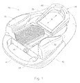
- FIG. 1 depicts an embodiment of a footswitch assembly 10.
- the surgical footswitch assembly 10 includes a body or housing that further includes bottom housing 12 and top housing 14, a foot pedal or treadle 16. All of which can be made from any suitable material, such as stainless steel, titanium or plastic. Other more embodiments may include additional a separate heel cup assembly 18 and a handle 4 positioned in the front. Side 10 or wing switches 20 may be placed on the top of housing 14 on either side of the foot pedal 16.
- Encoder assembly 22 translates the angular or pitch position of the foot pedal or treadle 16, which is tillable with respect to a horizontal plane or to a neutral or home plane, from a mechanical input based on the movement of the operator's foot into an electrical signal.
- the control input is preferably a linear control input.
- the neutral or home plane may provide the constant low input, and depression of the foot pedal may be used for the variable high input.
- FIG. 3 provides a functional diagram that illustrates how the footswitch 10 wirelessly couples to a surgical system 26.
- Footswitch 10 contains a mechanical input device such as pedal 16 that couples to encoder assembly 22 in order to produce a control signal that is provided to wireless interface 24.
- Wireless interface 24 is operable to establish a wireless communication pathway between footswitch 10 and surgical system 26.
- wireless interface 24 communicatively couples to wireless interface 30 of surgical console 28.
- the control signal(s) produced by encoder assembly 22 are able to be communicated to surgical console 28 via the wireless pathway.
- Surgical console 28 is operable to direct surgical equipment 30 based on the control signal(s) that are wirelessly relayed from the footswitch to the surgical console.
- FIG. 4 illustrates an additional embodiment of footswitch 10.
- footswitch 10 includes a mechanical input device such as pedal 16 that couples to encoder assembly 22 in order to provide a control signal to a surgical console via a wireless communication pathway established by wireless interface 24.
- This embodiment includes an internal power generator 34 operable to translate movement of footswitch 10 into stored energy operable to be used to power and operate the encoder assembly 22, wireless interface 24, and other components within footswitch 10.
- Internal power generator 34 may both generate and store energy with which to operate footswitch 10. This may eliminate potential failure of the footswitch during a procedure and overcome the need to replace batteries within the footswitch.
- the piezo electric effect is used to generate and store electrical energy
- the mechanical energy provided by the operator to depress the pedal may compress a piezo electric material that generates a voltage based on the mechanical energy exerted on the piezo electric material.
- This electrical energy may then be stored within a capacitor or rechargeable battery in order to provide a power reserve within the footswitch.
- the internal power generator may use inductive power generation wherein movement of the footswitch produces results in relative motion between an internal magnet and series of coils in order to charge a capacitor or rechargeable battery.
- Energy may also be stored in the form of mechanical energy wherein the pedal is used to spin a flywheel, which in essence is a mechanical battery. Flywheels store energy mechanically in the form of kinetic energy.
- air or other fluids can be compressed and stored and then this compressed air may be used to generate energy to power footswitch 10.
- a microprocessor or control circuit within the footswitch may prompt the operator to charge the footswitch should the stored energy within internal power generator 34 falls below a pre-determined level.
- the surgical console may direct the operator to charge the footswitch should the stored energy fall below a pre-determined level.
- An indicator such as a green LED on the footswitch, could indicate that the footswitch is powered and ready for use.
- the microprocessor or control circuit may be a single processing device or a plurality of processing devices.
- a processing device may be a microprocessor, micro-controller, digital signal processor, microcomputer, central processing unit, field programmable gate array, programmable logic device, state machine, logic circuitry, analog circuitry, digital circuitry, and/or any device that manipulates signals (analog and/or digital) based on operational instructions.
- the memory coupled to the microprocessor or control circuit may be a single memory device or a plurality of memory devices.
- Such a memory device may be a read-only memory, random access memory, volatile memory, non-volatile memory, static memory, dynamic memory, flash memory, cache memory, and/or any device that stores digital information.
- the memory storing the corresponding operational instructions may be embedded within, or external to, the circuitry comprising the state machine, analog circuitry, digital circuitry, and/or logic circuitry.
- the memory stores, and the microprocessor or control circuit executes, operational instructions corresponding to at least some of the steps and/or functions illustrated and described in association with FIG. 7.
- the ability to power the footswitch based on motion of the footswitch or the mechanical motion provided by the operator eliminates the need for batteries but more importantly it prompts the operator to recharge the footswitch prior to the power falling below a pre-determined level. This helps to ensure conditions where communications between the footswitch and a surgical console are interrupted by power failures in the footswitch that can result in improper control signals that have the potential to injure the patient. Additionally, guidelines or processes may be established and implemented by the microprocessor or control circuit such that should the wireless communications between the footswitch 10 and surgical console fail, the surgical equipment returns to a pre-determined position or mode of operation in order to prevent potential injury of a patient.
- footswitch assembly 10 may provide additional proportional control inputs utilizing heel cup assembly 18 which enables an arcuate movement.
- the heel cup assembly 18 is positioned at the rear portion of the footswitch 10 to engage the heel of the operator.
- the heel cup assembly 18 allows the operator to rotate the heel cup assembly 18 through an arcuate path while the operator's heel effectively remains in the same spot with respect to the footswitch assembly 10.
- This angular position mechanical input to a potentiometer produces an electrical signal received by encoder assembly 22.
- This electrical signal may be an additional control signal from the footswitch to the surgical system.
- This control signal may be either linear or non-linear.
- a simple on/off switch may be included in the heel cup assembly 18 to activate the signal output from the potentiometer 38.
- on/off switches could also be used to prevent inadvertent activation of the side switches 20.
- Such on/off switch may be a slide switch moving along a linear path within the heel cup assembly 18, as is designated by the arrow marked A' illustrated in FIG. 1.
- FIG. 5 illustrates another embodiment of footswitch 10 that extends the capability of footswitch 10.
- motion detector assembly 36 that may be powered by a cable or internal battery or self-powered as discussed previously with respect to internal power generator 34 within footswitch 10 may be worn by an operator.
- Motion detector assembly 36 transmits motion information to the surgical footswitch.
- the surgical footswitch receiving the motion information may produce additional control signal(s) based on the received information.
- the motion detector assembly may be tethered and physically connected to footswitch 10 or wirelessly coupled to footswitch 10.
- Motion detection assembly 36 transmits position information, which may take the form of relative position information with respect to footswitch 10, to the surgical footswitch. This information may then be passed to a system counsel and may be used as a one, two, or three dimensional linear switches. This motion detection assembly in combination with footswitch 10 enhances the control capability up to four independent dimensions.
- the localization of the motion detection assembly may be performed through many distinct methods.
- acceleration sensors may be incorporated within the motion detector assembly wherein the acceleration of the motion detector may be integrated over time to provide motion information.
- Another example may use radio triangulation through multiple received signals omitted within the surgical theater. This is a passive means of determining the motion information associated with the motion detector assembly.
- a radio frequency emitter within the motion detector assembly may produce signals that are received by various receivers coupled to either the surgical footswitch or surgical console wherein the footswitch or console is operable to process this information to produce both motion information associated with the motion detector assembly and a control signal resulting from the processing of the motion information.
- FIG. 6 provides a functional diagram of another embodiment of a surgical footswitch.
- surgical footswitch 10 includes a mechanical input device, such as pedal 16, an encoder assembly 22 and a wireless interface 24.
- This embodiment adds two switches that mechanically couple to the mechanical input device, first switch 38 and second switch 40.
- First switch activates a first control signal as pedal 16 orients passed a first determined point.
- switch 38 When switch 38 is activated a first control signal is produced that is operable to initialize surgical laser 40 within the surgical system.
- This first switch may be activated when the pedal 16 is initially depressed.
- the second switch produces a second control signal offset in time from the first control signal produced by the activation of switch 38.
- second switch 40 may be activated as pedal 16 nears the end of its angular motion, i.e. when the pedal is fully depressed. This second control signal may direct the firing of surgical laser 42.
- the trigger time between the activation of switch 38 and switch 40 allows the stress on the laser to be reduced as laser 42 may not be ramped to power.
- the trigger time between the activation of the first switch and second switch allows the laser to "slowly" warm up before firing.
- the trigger time between the activation of the two switches is between about 100 milliseconds and 300 milliseconds. The actual time may depend on the foot speed of the operator. This allows laser 42 to be slowly ramped to power over a span of about 100 milliseconds to about 300 milliseconds. This is particularly useful as certain lasers known to those having the skill in the art that cannot be turned on in less than 50 milliseconds.
- the reduced stress associated with firing the laser will result in an improved laser performance and reliability.
- footswitch 10 is illustrated in this environment as establishing a wireless communication pathway between the footswitch and surgical laser 42, footswitch 10 may physically couple to the control circuits associated with initializing and firing laser 42.
- FIG. 7 provides a logic flow diagram illustrating the method of controlling surgical equipment in accordance with embodiments of the present invention.
- This method involves repositioning a mechanical devise within a footswitch in step 700.
- This footswitch may be powered by an internal power generator operable to translate footswitch movement into stored energy. This allows the footswitch to be self powered and eliminates the need to physically couple the footswitch to surgical console or power supply. Additionally, this may eliminate the potential hazards associated with power failures within the footswitch during a medical procedure.
- the repositioning of the pedal within the surgical footswitch may serve two purposes. First, it may provide mechanical energy which may be translated and stored as energy to operate the footswitch. Additionally, control signals may be generated based on the motion and positioning of the pedal. Additional switches or mechanical assemblies within the footswitch may also receive mechanical input that can be translated into control signals.
- the pedal or mechanical device couples to an encoder in step 702. This allows the encoder to generate control signal(s) based on the repositioning of the mechanical device or pedal in step 704.
- the footswitch wirelessly couples to the surgical console in step 706. This wireless coupling facilitates the transfer of data and other information between the footswitch and surgical console.
- the control signal from the footswitch is passed wirelessly to the surgical console.
- the surgical console in step 710 is operable to direct surgical equipment coupled to the console based on the received control signals.
- the internal power generator translates footswitch movement into stored energy using processes such as an inductive power generator, piezo electric power generator, or other like processes known to those skilled in the art. This eliminates potential hazards associated with power failures within the footswitch that can result in unexpected control signals that produce potentially hazardous situations during surgery that could endanger a patient.
- a wireless coupling between the footswitch and surgical console may be monitored wherein a communication failure may result in a processor or control circuit within the surgical console directing the surgical equipment to a safe condition in order to avoid potential harm to a patient.
- the present invention provides a surgical footswitch that includes a base, a pedal, an encoder assembly, a wireless interface, and an internal power generator.
- the pedal mounts upon the base and pivots.
- the encoder assembly couples to the pedal. As the pedal pivots, the encoder assembly translates the mechanical signal of the pedal into a control signal based on the pedals position and/or orientation.
- the wireless interface couples the encoder assembly to receive the control signal.
- the wireless interface also couples the surgical footswitch to a surgical console operable to control and direct surgical equipment. The wireless interface passes the control signal from the encoder to the surgical console, which then directs the surgical equipment based on the control signal.
- This wireless interface eliminates the tangle of wires or tethers, which may be a hazard in the surgical theater.
- the internal power generator translates footswitch movement into stored energy to eliminate potential failures of the footswitch during a procedure and overcome the need to replace batteries within the footswitch.
- Other embodiments may extend the capability of the surgical footswitches with motion detector assembly that may be worn by a user. These motion detectors transmit motion information to the surgical footswitch. The encoder assembly may then generate additional control signals based on the received motion information.
- a dual switch surgical footswitch operable to ramp and fire a surgical laser.
- the first switch couples to the pedal and is activated as the pedal orients past the first predetermined point when the pedal is initially depressed.
- a first control signal initializes the laser within the surgical system.
- the second switch also operably couples to the pedal and is activated when the pedal orients past a second predetermined point. This second control signal directs the firing of the ramped laser.
- the trigger time between the activation of the first switch and the second switch allows stress on the laser to be relieved by allowing the laser to be ramped to power.
- the term “substantially” or “approximately”, as may be used herein, provides an industry-accepted tolerance to its corresponding term. Such an industry-accepted tolerance ranges from less than one percent to twenty percent and corresponds to, but is not limited to, component values, integrated circuit process variations, temperature variations, rise and fall times, and/or thermal noise.
- the term “operably coupled”, as may be used herein, includes direct coupling and indirect coupling via another component, element, circuit, or module where, for indirect coupling, the intervening component, element, circuit, or module does not modify the information of a signal but may adjust its current level, voltage level, and/or power level.
- inferred coupling includes direct and indirect coupling between two elements in the same manner as “operably coupled”.
- the term "compares favorably”, as may be used herein indicates that a comparison between two or more elements, items, signals, etc., provides a desired relationship. For example, when the desired relationship is that signal 1 has a greater magnitude than signal 2, a favorable comparison may be achieved when the magnitude of signal 1 is greater than that of signal 2 or when the magnitude of signal 2 is less than that of signal 1.
Abstract
Description
- The present invention relates generally to surgical footswitches, and more particularly, a secure reliable system and method operable to wirelessly control complex surgical systems.
- During the use of a complex patient treatment apparatus or surgical system, for example, surgical equipment used when performing ophthalmic surgery, the control of a variety of different subsystems such as pneumatic and electronically driven subsystems may be required. Typically, the operation of the subsystems is controlled by a microprocessor-driven console. The microprocessor controls within a surgical console receive mechanical inputs from either the operator of the surgical system or from an assistant. A control input device, such as a footswitch, is often used to accept mechanical inputs. These mechanical inputs originate from the movement of the foot of an operator to govern the operation of a subsystem within the patient treatment apparatus. The mechanical inputs from the movement of the foot of the operator are translated into electrical signals which are fed to the microprocessor controls. The electrical signals are then used to control the operational characteristics of a subsystem in a complex patient treatment apparatus.
- Examples of footswitches that are designed for receiving mechanical inputs from the movement of the foot of an operator of a complex patient treatment apparatus may be found in several U.S. patents, including
U.S. Patent Nos. 4,837,857 (Scheller, et al. ),4,965,417 (Massie ),4,983,901 (Lehmer ),5,091,656 (Gahn ),5,268,624 (Zanger ),5,554,894 (Sepielli ),5,580,347 5 (Reimels 5,635,777 (Telymonde, et al ),5,787,760 (Thorlakson ),5,983,749 (Holtorf ),and6,179,829 B1 (Bisch, et al ), and inInternational Patent Application Publication Nos. WO 98/08442 (Bisch, et al. WO 00/12037 (Chen WO 02/01310 (Chen - In more complex footswitch assemblies, side or wing switches may be added to housings on either side of the foot pedal in order to provide additional capabilities to the footswitch. The condition of these side or wing switches is changed by the application of pressure from the front portion of the operator's foot or from the rear portion of the operator's foot.
- As these footswitches become more complex, the need to establish secure reliable communications between the footswitch and the surgical console has resulted in a number of wired pathways that connect the footswitch and surgical console. As the footswitches are moved about the operating room, these tethers, wires and cables can become tangled with other equipment. Accidentally disconnecting these cables can result in improper control inputs that have the potential to injure a patient. Therefore a need exists for a reliable footswitch operable to communicate with the surgical system while avoiding the potential hazardous or restrictive environment created by entangled cables.
- The present invention provides a surgical footswitch used to control surgical equipment that substantial addresses the above-identified needs as well as others.
- One embodiment provides a surgical footswitch having a base, a pedal, an encoder assembly, and a wireless interface. The pedal mounts upon the base and pivots. The encoder assembly couples to the pedal. As the pedal pivots, the encoder assembly translates the mechanical signal of the pedal into a control signal based on the pedals position and/or orientation. The wireless interface couples the encoder assembly to receive the control signal. The wireless interface also couples the surgical footswitch to a surgical console operable to control and direct surgical equipment. The wireless interface passes the control signal from the encoder to the surgical console, which then directs the surgical equipment based on the control signal. This wireless interface eliminates the tangle of wires or tethers, which may be a hazard in the surgical theater.
- Another embodiment further includes an internal power generator operable to translate footswitch movement into stored energy. This may eliminate a potential failure of the footswitch during a procedure and overcome the need to replace batteries within the footswitch as the surgical footswitch can generate its own power. There are many different ways to derive power from the movement of the surgical footswitch. These include but should not be limited to the piezo electric effect, inductive power generation, compressing and storing air, mechanical flywheels or other like means known to those having skill in the art.
- Another embodiment provides a surgical footswitch having a base, a pedal, an encoder, a motion detector, and a wireless interface. This embodiment extends the capability of existing surgical footswitches wherein the motion detector assembly may be worn by a user and transmit motion information to the surgical footswitch. The encoder assembly may generate additional control signals based on the received motion information. The motion detector may generate motion information based on relative positioning information, acceleration sensor used to determine the motion detector assembly's position through integration, radio triangulation or other like methods known to those having skill in the art.
- Yet another embodiment provides a dual switch surgical footswitch operable to ramp and fire a surgical laser. This dual switch surgical footswitch includes a base, pedal, first switch, second switch, encoder assembly, and interface. The pedal is mounted to the base and operable to pivot about a plane associated with the base. The first switch couples to the pedal and is activated as the pedal orients past the first predetermined point when the pedal is initially depressed. When the first switch is activated a first control signal initializes the laser within the surgical system. The second switch also operably couples to the pedal and is activated when the pedal orients past a second predetermined point such as reaching the bottom of the range of motion. This second control signal directs the firing of the ramped laser. The trigger time between the activation of the first switch and the second switch allows stress on the laser to be relieved by allowing the laser to be ramped to power.
- An encoder assembly coupled to the pedal may be operable to produce a third control signal based on the pedal's position and for orientation. The interface couples to the encoder and establishes a communication path between the surgical footswitch and the surgical console. This surgical consol is operable to control or direct the surgical equipment based on the control signals.
- For a more complete understanding of the present invention and the advantages thereof, reference is now made to the following description taken in conjunction with the accompanying drawings in which like reference numerals indicate like features and wherein:
- FIG. 1 depicts an embodiment of a footswitch assembly in accordance with an embodiment of the present invention;
- FIG. 2 provides a cross sectional view of an embodiment of a footswitch assembly in accordance with an embodiment of the present invention;
- FIG. 3 provides a functional diagram that illustrates how the footswitch wirelessly couples to a surgical system in accordance with an embodiment of the present invention;
- FIG. 4 depicts an embodiment of a footswitch assembly in accordance with an embodiment of the present invention;
- FIG. 5 illustrates another embodiment of footswitch that extends the capability of footswitch in accordance with an embodiment of the present invention;
- FIG. 6 provides a functional diagram of another embodiment of a surgical footswitch in accordance with an embodiment of the present invention; and
- FIG. 7 provides a logic flow diagram illustrating the method of controlling surgical equipment in accordance with embodiments of the present invention.
- Preferred embodiments of the present invention are illustrated in the FIGs., like numerals being used to refer to like and corresponding parts of the various drawings.
- FIG. 1 depicts an embodiment of a
footswitch assembly 10. Thesurgical footswitch assembly 10 includes a body or housing that further includesbottom housing 12 andtop housing 14, a foot pedal ortreadle 16. All of which can be made from any suitable material, such as stainless steel, titanium or plastic. Other more embodiments may include additional a separateheel cup assembly 18 and ahandle 4 positioned in the front.Side 10 or wing switches 20 may be placed on the top ofhousing 14 on either side of thefoot pedal 16. - Attached to the foot pedal or
tillable treadle 16 is anencoder assembly 22 as illustrated in the cross section provided by FIG. 2.Encoder assembly 22 translates the angular or pitch position of the foot pedal ortreadle 16, which is tillable with respect to a horizontal plane or to a neutral or home plane, from a mechanical input based on the movement of the operator's foot into an electrical signal. Thus, thepitch 15 movement of the foot pedal ortillable treadle 16, typically in a downward direction, provides a control input. The control input is preferably a linear control input. However, when a variable high input and a constant low input is satisfactory, the neutral or home plane may provide the constant low input, and depression of the foot pedal may be used for the variable high input. - FIG. 3 provides a functional diagram that illustrates how the
footswitch 10 wirelessly couples to asurgical system 26.Footswitch 10 contains a mechanical input device such aspedal 16 that couples toencoder assembly 22 in order to produce a control signal that is provided towireless interface 24.Wireless interface 24 is operable to establish a wireless communication pathway betweenfootswitch 10 andsurgical system 26. Specifically,wireless interface 24 communicatively couples towireless interface 30 ofsurgical console 28. Thus, the control signal(s) produced byencoder assembly 22 are able to be communicated tosurgical console 28 via the wireless pathway.Surgical console 28 is operable to directsurgical equipment 30 based on the control signal(s) that are wirelessly relayed from the footswitch to the surgical console. - FIG. 4 illustrates an additional embodiment of
footswitch 10. As previously stated,footswitch 10 includes a mechanical input device such aspedal 16 that couples toencoder assembly 22 in order to provide a control signal to a surgical console via a wireless communication pathway established bywireless interface 24. This embodiment includes aninternal power generator 34 operable to translate movement offootswitch 10 into stored energy operable to be used to power and operate theencoder assembly 22,wireless interface 24, and other components withinfootswitch 10. -
Internal power generator 34 may both generate and store energy with which to operatefootswitch 10. This may eliminate potential failure of the footswitch during a procedure and overcome the need to replace batteries within the footswitch. There are many different ways to derive power from the movement of the surgical footswitch. These include but should not be limited to the piezo electric effect, inductive power generation, the compression storage of compressed fluids such as air, mechanical flywheels, or other like means known to those having skill in the art. For example, when the piezo electric effect is used to generate and store electrical energy, the mechanical energy provided by the operator to depress the pedal may compress a piezo electric material that generates a voltage based on the mechanical energy exerted on the piezo electric material. This electrical energy may then be stored within a capacitor or rechargeable battery in order to provide a power reserve within the footswitch. In another embodiment, the internal power generator may use inductive power generation wherein movement of the footswitch produces results in relative motion between an internal magnet and series of coils in order to charge a capacitor or rechargeable battery. Energy may also be stored in the form of mechanical energy wherein the pedal is used to spin a flywheel, which in essence is a mechanical battery. Flywheels store energy mechanically in the form of kinetic energy. Alternatively, air or other fluids can be compressed and stored and then this compressed air may be used to generate energy topower footswitch 10. These are just examples of howinternal power generator 34 may generate and store energy within the footswitch. - A microprocessor or control circuit within the footswitch may prompt the operator to charge the footswitch should the stored energy within
internal power generator 34 falls below a pre-determined level. Alternatively, the surgical console may direct the operator to charge the footswitch should the stored energy fall below a pre-determined level. An indicator, such as a green LED on the footswitch, could indicate that the footswitch is powered and ready for use. - The microprocessor or control circuit may be a single processing device or a plurality of processing devices. Such a processing device may be a microprocessor, micro-controller, digital signal processor, microcomputer, central processing unit, field programmable gate array, programmable logic device, state machine, logic circuitry, analog circuitry, digital circuitry, and/or any device that manipulates signals (analog and/or digital) based on operational instructions. The memory coupled to the microprocessor or control circuit may be a single memory device or a plurality of memory devices. Such a memory device may be a read-only memory, random access memory, volatile memory, non-volatile memory, static memory, dynamic memory, flash memory, cache memory, and/or any device that stores digital information. Note that when the microprocessor or control circuit implements one or more of its functions via a state machine, analog circuitry, digital circuitry, and/or logic circuitry, the memory storing the corresponding operational instructions may be embedded within, or external to, the circuitry comprising the state machine, analog circuitry, digital circuitry, and/or logic circuitry. The memory stores, and the microprocessor or control circuit executes, operational instructions corresponding to at least some of the steps and/or functions illustrated and described in association with FIG. 7.
- The ability to power the footswitch based on motion of the footswitch or the mechanical motion provided by the operator eliminates the need for batteries but more importantly it prompts the operator to recharge the footswitch prior to the power falling below a pre-determined level. This helps to ensure conditions where communications between the footswitch and a surgical console are interrupted by power failures in the footswitch that can result in improper control signals that have the potential to injure the patient. Additionally, guidelines or processes may be established and implemented by the microprocessor or control circuit such that should the wireless communications between the footswitch 10 and surgical console fail, the surgical equipment returns to a pre-determined position or mode of operation in order to prevent potential injury of a patient.
- Returning to FIG. 1,
footswitch assembly 10 may provide additional proportional control inputs utilizingheel cup assembly 18 which enables an arcuate movement. As shown in the drawing FIGs., theheel cup assembly 18 is positioned at the rear portion of thefootswitch 10 to engage the heel of the operator. Theheel cup assembly 18 allows the operator to rotate theheel cup assembly 18 through an arcuate path while the operator's heel effectively remains in the same spot with respect to thefootswitch assembly 10. This angular position mechanical input to a potentiometer produces an electrical signal received byencoder assembly 22. This electrical signal may be an additional control signal from the footswitch to the surgical system. This control signal may be either linear or non-linear. - To further enhance operator control, a simple on/off switch, well known to those of ordinary skill in the art, may be included in the
heel cup assembly 18 to activate the signal output from thepotentiometer 38. Alternatively, such on/off switches could also be used to prevent inadvertent activation of the side switches 20. Such on/off switch may be a slide switch moving along a linear path within theheel cup assembly 18, as is designated by the arrow marked A' illustrated in FIG. 1. - FIG. 5 illustrates another embodiment of
footswitch 10 that extends the capability offootswitch 10. Specifically,motion detector assembly 36 that may be powered by a cable or internal battery or self-powered as discussed previously with respect tointernal power generator 34 withinfootswitch 10 may be worn by an operator.Motion detector assembly 36 transmits motion information to the surgical footswitch. The surgical footswitch receiving the motion information may produce additional control signal(s) based on the received information. The motion detector assembly may be tethered and physically connected to footswitch 10 or wirelessly coupled tofootswitch 10. - The operator may wear
motion detector assembly 36 on any desired body part such as the knee, foot, arm, waist, head, fingers, shoulder. Specific embodiments may prefer to wear the motion detection assembly on the knee.Motion detection assembly 36 transmits position information, which may take the form of relative position information with respect tofootswitch 10, to the surgical footswitch. This information may then be passed to a system counsel and may be used as a one, two, or three dimensional linear switches. This motion detection assembly in combination withfootswitch 10 enhances the control capability up to four independent dimensions. - The localization of the motion detection assembly may be performed through many distinct methods. For example, acceleration sensors may be incorporated within the motion detector assembly wherein the acceleration of the motion detector may be integrated over time to provide motion information. Another example may use radio triangulation through multiple received signals omitted within the surgical theater. This is a passive means of determining the motion information associated with the motion detector assembly. Alternatively, a radio frequency emitter within the motion detector assembly may produce signals that are received by various receivers coupled to either the surgical footswitch or surgical console wherein the footswitch or console is operable to process this information to produce both motion information associated with the motion detector assembly and a control signal resulting from the processing of the motion information.
- FIG. 6 provides a functional diagram of another embodiment of a surgical footswitch. Here
surgical footswitch 10 includes a mechanical input device, such aspedal 16, anencoder assembly 22 and awireless interface 24. This embodiment adds two switches that mechanically couple to the mechanical input device,first switch 38 andsecond switch 40. First switch activates a first control signal aspedal 16 orients passed a first determined point. Whenswitch 38 is activated a first control signal is produced that is operable to initializesurgical laser 40 within the surgical system. This first switch may be activated when thepedal 16 is initially depressed. The second switch produces a second control signal offset in time from the first control signal produced by the activation ofswitch 38. For example,second switch 40 may be activated aspedal 16 nears the end of its angular motion, i.e. when the pedal is fully depressed. This second control signal may direct the firing of surgical laser 42. - The trigger time between the activation of
switch 38 andswitch 40 allows the stress on the laser to be reduced as laser 42 may not be ramped to power. The trigger time between the activation of the first switch and second switch allows the laser to "slowly" warm up before firing. In one embodiment the trigger time between the activation of the two switches is between about 100 milliseconds and 300 milliseconds. The actual time may depend on the foot speed of the operator. This allows laser 42 to be slowly ramped to power over a span of about 100 milliseconds to about 300 milliseconds. This is particularly useful as certain lasers known to those having the skill in the art that cannot be turned on in less than 50 milliseconds. The reduced stress associated with firing the laser will result in an improved laser performance and reliability. Althoughfootswitch 10 is illustrated in this environment as establishing a wireless communication pathway between the footswitch and surgical laser 42,footswitch 10 may physically couple to the control circuits associated with initializing and firing laser 42. - FIG. 7 provides a logic flow diagram illustrating the method of controlling surgical equipment in accordance with embodiments of the present invention. This method involves repositioning a mechanical devise within a footswitch in
step 700. This footswitch may be powered by an internal power generator operable to translate footswitch movement into stored energy. This allows the footswitch to be self powered and eliminates the need to physically couple the footswitch to surgical console or power supply. Additionally, this may eliminate the potential hazards associated with power failures within the footswitch during a medical procedure. The repositioning of the pedal within the surgical footswitch may serve two purposes. First, it may provide mechanical energy which may be translated and stored as energy to operate the footswitch. Additionally, control signals may be generated based on the motion and positioning of the pedal. Additional switches or mechanical assemblies within the footswitch may also receive mechanical input that can be translated into control signals. - The pedal or mechanical device couples to an encoder in
step 702. This allows the encoder to generate control signal(s) based on the repositioning of the mechanical device or pedal instep 704. The footswitch wirelessly couples to the surgical console instep 706. This wireless coupling facilitates the transfer of data and other information between the footswitch and surgical console. Instep 708, the control signal from the footswitch is passed wirelessly to the surgical console. The surgical console instep 710 is operable to direct surgical equipment coupled to the console based on the received control signals. - In the embodiments where the footswitch has an internal power generator, the internal power generator translates footswitch movement into stored energy using processes such as an inductive power generator, piezo electric power generator, or other like processes known to those skilled in the art. This eliminates potential hazards associated with power failures within the footswitch that can result in unexpected control signals that produce potentially hazardous situations during surgery that could endanger a patient. A wireless coupling between the footswitch and surgical console may be monitored wherein a communication failure may result in a processor or control circuit within the surgical console directing the surgical equipment to a safe condition in order to avoid potential harm to a patient.
- In summary, the present invention provides a surgical footswitch that includes a base, a pedal, an encoder assembly, a wireless interface, and an internal power generator. The pedal mounts upon the base and pivots. The encoder assembly couples to the pedal. As the pedal pivots, the encoder assembly translates the mechanical signal of the pedal into a control signal based on the pedals position and/or orientation. The wireless interface couples the encoder assembly to receive the control signal. The wireless interface also couples the surgical footswitch to a surgical console operable to control and direct surgical equipment. The wireless interface passes the control signal from the encoder to the surgical console, which then directs the surgical equipment based on the control signal. This wireless interface eliminates the tangle of wires or tethers, which may be a hazard in the surgical theater. The internal power generator translates footswitch movement into stored energy to eliminate potential failures of the footswitch during a procedure and overcome the need to replace batteries within the footswitch.
- Other embodiments may extend the capability of the surgical footswitches with motion detector assembly that may be worn by a user. These motion detectors transmit motion information to the surgical footswitch. The encoder assembly may then generate additional control signals based on the received motion information.
- Finally, other embodiments provide a dual switch surgical footswitch operable to ramp and fire a surgical laser. The first switch couples to the pedal and is activated as the pedal orients past the first predetermined point when the pedal is initially depressed. When the first switch is activated a first control signal initializes the laser within the surgical system. The second switch also operably couples to the pedal and is activated when the pedal orients past a second predetermined point. This second control signal directs the firing of the ramped laser. The trigger time between the activation of the first switch and the second switch allows stress on the laser to be relieved by allowing the laser to be ramped to power.
- As one of average skill in the art will appreciate, the term "substantially" or "approximately", as may be used herein, provides an industry-accepted tolerance to its corresponding term. Such an industry-accepted tolerance ranges from less than one percent to twenty percent and corresponds to, but is not limited to, component values, integrated circuit process variations, temperature variations, rise and fall times, and/or thermal noise. As one of average skill in the art will further appreciate, the term "operably coupled", as may be used herein, includes direct coupling and indirect coupling via another component, element, circuit, or module where, for indirect coupling, the intervening component, element, circuit, or module does not modify the information of a signal but may adjust its current level, voltage level, and/or power level. As one of average skill in the art will also appreciate, inferred coupling (i.e., where one element is coupled to another element by inference) includes direct and indirect coupling between two elements in the same manner as "operably coupled". As one of average skill in the art will further appreciate, the term "compares favorably", as may be used herein, indicates that a comparison between two or more elements, items, signals, etc., provides a desired relationship. For example, when the desired relationship is that signal 1 has a greater magnitude than signal 2, a favorable comparison may be achieved when the magnitude of signal 1 is greater than that of signal 2 or when the magnitude of signal 2 is less than that of signal 1.
- Although the present invention is described in detail, it should be understood that various changes, substitutions and alterations can be made hereto without departing from the spirit and scope of the invention as described by the appended claims.
Claims (30)
- A surgical footswitch (10) comprising:a base;a pedal (16) mounted to the base;an encoder assembly (22) coupled to the pedal, wherein the encoder assembly is operable to produce a control signal based on the pedals position and/or orientation; anda wireless interface (24) communicatively coupled to the encoder assembly, wherein the wireless interface is operable to communicatively couple the surgical footswitch to a surgical console (28), and wherein the surgical console is operable to control surgical equipment (32) based on the control signal.
- The surgical footswitch of Claim 1, further comprising an internal power generator (34) operable to translate footswitch movement into stored energy, and wherein the internal power generator is operable to power the surgical footswitch (10).
- The surgical footswitch of Claim 2, wherein the internal power generator (34) comprises an inductive power generator.
- The surgical footswitch of Claim 2, wherein the internal power generator (34) comprises a piezo electrical power generator.
- The surgical footswitch of Claim 2, wherein the stored energy is stored within a device selected from the group consisting of a capacitor, a rechargeable battery, a flywheel, and a compressed fluid reservoir.
- The surgical footswitch of Claim 2, wherein the surgical console (28) directs the surgical equipment (32) to a predetermined state when wireless communications between the surgical footswitch and the surgical console are interrupted.
- The surgical footswitch of Claim 2, further comprising a ready indicator, wherein the ready indicator provides a ready indication when the stored energy exceeds a predetermined level.
- The surgical footswitch of Claim 7, wherein the surgical console (28) only accepts the control signal when the stored energy exceeds a predetermined level.
- The surgical footswitch of any one of Claims 1 to 7, further comprising;a motion detector assembly (36) operable to be worn by a user and to transmit motion information to the surgical console (28) via the surgical footswitch (10), wherein the surgical console is operable to produce an additional control signal based on the received motion information.
- The surgical footswitch of Claim 9, wherein the encoder assembly (22) is operable to produce the additional control signal.
- The surgical footswitch of Claim 9, wherein the motion detector (36) receives at least one radio frequency (RF) signal from at least one transmitter located at a predetermined location.
- The surgical footswitch of Claim 11, wherein the at least one transmitter is coupled to the surgical console (28).
- The surgical footswitch of Claim 9, wherein the motion detector (36) further comprises acceleration sensors operable to produce motion information.
- The surgical footswitch of Claim 13, wherein the outputs of the acceleration sensors may be integrated over time to produce motion information.
- The surgical footswitch of any one of Claims 9 to 14, wherein the motion detector (36) wirelessly couples to the surgical footswitch.
- The surgical footswitch of any one of Claims 9 to 14, wherein the motion detector (36) couples to the surgical footswitch via a tether.
- The surgical footswitch of any one of Claims 9 to 16, wherein the motion detector (36) further comprises an internal power generator operable to translate stored motion into stored energy operable to power the motion detector.
- The surgical footswitch of any one of Claims 1 to 17, adapted as a dual switch footswitch operable to fire a laser (42), comprising:a first switch (3 8) operably coupled to the pedal, wherein the first switch activates a first control signal as the pedal orients past a first predetermined point, and wherein the first control signal is operable to initialise a laser within a surgical system; anda second switch (40) operably coupled to the pedal, wherein the second switch activates a second control signal as the pedal orients past a second predetermined point, and wherein the second control signal is operable to fire the laser.
- The surgical footswitch of Claim 18, wherein the trigger time between activation of the first switch (38) and the second switch (40) is between 100ms and 300 ms.
- The surgical footswitch of Claim 19, wherein the trigger time relieves stress on the laser (42).
- The surgical footswitch of Claim 19, wherein the trigger time allows the laser (42) to be ramped to power.
- A method of controlling surgical equipment, comprising:repositioning (700) a pedal (16) within a surgical footswitch;coupling (702) the pedal to an encoder (22), wherein the encoder is operable to generate (704) a control signal based on repositioning of the pedal;wirelessly coupling (706) the surgical footswitch to a surgical console;wirelessly providing (708) control signals to the surgical console; anddirecting (710) the surgical equipment with the surgical console and based on the control signal.
- The method of Claim 22, further comprising powering the surgical footswitch with an internal power generator operable to translate footswitch movement into stored energy.
- The method of Claim 23, comprising powering the surgical footswitch with an inductive power generator or a piezo electrical power generator.
- The method of Claim 22, wherein the surgical console directs the surgical equipment to a predetermined state when wireless communications between the surgical footswitch and the surgical console are interrupted.
- The method of any of Claims 22 to 25, further comprising;mounting a motion detector on a user;communicatively coupling the motion detector to the surgical footswitch;transmitting motion information from the motion detector to the surgical footswitch, wherein the encoder is operable to generate a second control signal based on motion information; anddirecting the surgical equipment with the surgical console and based on the second control signal.
- The method of Claim 26, further comprising wirelessly coupling the motion detector assembly and the surgical footswitch.
- The method of any of Claims 22 to 27, adapted for firing a laser (42) with a dual switch surgical footswitch, comprising;pivoting a pedal about a plane associated with a base of the surgical footswitch;activating a first switch to generate a first control signal as the pedal orients past a first predetermined point;initialising the surgical laser when the first switch is activated;activating a second switch to generate a second control signal as the pedal orients past a second predetermined point; andfiring the surgical laser when the second switch is activated.
- The method of Claim 28, wherein a trigger time between activation of the first switch and the second switch is set between 100ms and 300ms.
- The method of Claim 28, wherein initialising the surgical laser comprises ramping the laser to power.
Priority Applications (1)
| Application Number | Priority Date | Filing Date | Title |
|---|---|---|---|
| EP20080163207 EP1994888A1 (en) | 2005-03-31 | 2006-03-20 | Wireless footswitch with internal power generator |
Applications Claiming Priority (1)
| Application Number | Priority Date | Filing Date | Title |
|---|---|---|---|
| US66729005P | 2005-03-31 | 2005-03-31 |
Related Child Applications (1)
| Application Number | Title | Priority Date | Filing Date |
|---|---|---|---|
| EP20080163207 Division EP1994888A1 (en) | 2005-03-31 | 2006-03-20 | Wireless footswitch with internal power generator |
Publications (2)
| Publication Number | Publication Date |
|---|---|
| EP1714617A1 true EP1714617A1 (en) | 2006-10-25 |
| EP1714617B1 EP1714617B1 (en) | 2009-09-02 |
Family
ID=36593692
Family Applications (2)
| Application Number | Title | Priority Date | Filing Date |
|---|---|---|---|
| EP20080163207 Withdrawn EP1994888A1 (en) | 2005-03-31 | 2006-03-20 | Wireless footswitch with internal power generator |
| EP20060111409 Active EP1714617B1 (en) | 2005-03-31 | 2006-03-20 | Footswitch operable to control a surgical system |
Family Applications Before (1)
| Application Number | Title | Priority Date | Filing Date |
|---|---|---|---|
| EP20080163207 Withdrawn EP1994888A1 (en) | 2005-03-31 | 2006-03-20 | Wireless footswitch with internal power generator |
Country Status (9)
| Country | Link |
|---|---|
| US (2) | US7781941B2 (en) |
| EP (2) | EP1994888A1 (en) |
| JP (4) | JP5073958B2 (en) |
| AT (1) | ATE441362T1 (en) |
| AU (1) | AU2006201371B2 (en) |
| BR (1) | BRPI0601901B1 (en) |
| CA (2) | CA2539271C (en) |
| DE (1) | DE602006008853D1 (en) |
| ES (1) | ES2330780T3 (en) |
Cited By (21)
| Publication number | Priority date | Publication date | Assignee | Title |
|---|---|---|---|---|
| EP1897105A2 (en) * | 2005-06-30 | 2008-03-12 | Alcon Inc. | Multifunction surgical footswitch |
| EP2346432A1 (en) * | 2008-10-24 | 2011-07-27 | Discus Dental, LLC | Hand-held portable laser surgical device |
| US8357175B2 (en) | 2008-12-16 | 2013-01-22 | Nico Corporation | Positioning system for tissue removal device |
| US8430825B2 (en) | 2008-12-16 | 2013-04-30 | Nico Corporation | Tissue removal device for neurosurgical and spinal surgery applications |
| US8460327B2 (en) | 2008-12-16 | 2013-06-11 | Nico Corporation | Tissue removal device for neurosurgical and spinal surgery applications |
| US8496599B2 (en) | 2008-12-16 | 2013-07-30 | Nico Corporation | Tissue removal device for neurosurgical and spinal surgery applications |
| US8657841B2 (en) | 2008-12-16 | 2014-02-25 | Nico Corporation | Tissue removal device for neurosurgical and spinal surgery applications |
| US8702738B2 (en) | 2008-12-16 | 2014-04-22 | Nico Corporation | Tissue removal device for neurosurgical and spinal surgery applications |
| US9216031B2 (en) | 2008-12-16 | 2015-12-22 | Nico Corporation | Tissue removal device with adjustable fluid supply sleeve for neurosurgical and spinal surgery applications |
| US9279751B2 (en) | 2008-12-16 | 2016-03-08 | Nico Corporation | System and method of taking and collecting tissue cores for treatment |
| US9504247B2 (en) | 2008-12-16 | 2016-11-29 | Nico Corporation | System for collecting and preserving tissue cores |
| US9655639B2 (en) | 2008-12-16 | 2017-05-23 | Nico Corporation | Tissue removal device for use with imaging devices in neurosurgical and spinal surgery applications |
| US9820480B2 (en) | 2008-12-16 | 2017-11-21 | Nico Corporation | System for collecting and preserving tissue cores |
| US9931105B2 (en) | 2008-12-16 | 2018-04-03 | Nico Corporation | System and method of taking and collecting tissue cores for treatment |
| US10080578B2 (en) | 2008-12-16 | 2018-09-25 | Nico Corporation | Tissue removal device with adjustable delivery sleeve for neurosurgical and spinal surgery applications |
| EP2134286B1 (en) * | 2007-03-20 | 2018-11-21 | Kaltenbach & Voigt GmbH | Arrangement for controlling medicinal devices, in particular of a dental work station |
| EP3311765A4 (en) * | 2015-06-17 | 2019-02-20 | Olympus Corporation | Energy treatment tool |
| US10368890B2 (en) | 2008-12-16 | 2019-08-06 | Nico Corporation | Multi-functional surgical device for neurosurgical and spinal surgery applications |
| WO2020039349A1 (en) * | 2018-08-21 | 2020-02-27 | Alcon Inc. | Multi-functional surgical foot controller with integrated shroud |
| IT201800009786A1 (en) * | 2018-10-25 | 2020-04-25 | Comepi Srl | STRUCTURE OF MODULAR MICROSWITCH |
| US10895920B2 (en) | 2013-11-15 | 2021-01-19 | Eric K-Laflamme | Pneumatically actuated computer input device |
Families Citing this family (90)
| Publication number | Priority date | Publication date | Assignee | Title |
|---|---|---|---|---|
| CA2539271C (en) | 2005-03-31 | 2014-10-28 | Alcon, Inc. | Footswitch operable to control a surgical system |
| US8380126B1 (en) | 2005-10-13 | 2013-02-19 | Abbott Medical Optics Inc. | Reliable communications for wireless devices |
| US8565839B2 (en) | 2005-10-13 | 2013-10-22 | Abbott Medical Optics Inc. | Power management for wireless devices |
| US7636549B2 (en) | 2006-04-21 | 2009-12-22 | Abbott Medical Optics Inc. | Automated bonding for wireless devices |
| US8414534B2 (en) | 2006-11-09 | 2013-04-09 | Abbott Medical Optics Inc. | Holding tank devices, systems, and methods for surgical fluidics cassette |
| US8491528B2 (en) | 2006-11-09 | 2013-07-23 | Abbott Medical Optics Inc. | Critical alignment of fluidics cassettes |
| US9522221B2 (en) | 2006-11-09 | 2016-12-20 | Abbott Medical Optics Inc. | Fluidics cassette for ocular surgical system |
| US9295765B2 (en) | 2006-11-09 | 2016-03-29 | Abbott Medical Optics Inc. | Surgical fluidics cassette supporting multiple pumps |
| US10959881B2 (en) | 2006-11-09 | 2021-03-30 | Johnson & Johnson Surgical Vision, Inc. | Fluidics cassette for ocular surgical system |
| US8465473B2 (en) | 2007-03-28 | 2013-06-18 | Novartis Ag | Surgical footswitch with movable shroud |
| US20110088151A1 (en) * | 2007-04-17 | 2011-04-21 | Semra Peksoz | Firefighter's turnout coat with seamless collar |
| DE102007018811B4 (en) * | 2007-04-20 | 2009-07-09 | Siemens Ag | Device with a movable patient table and / or ceiling stand and method for enabling the movement of a movable patient table and / or ceiling stand only by an authorized operator |
| US10596032B2 (en) | 2007-05-24 | 2020-03-24 | Johnson & Johnson Surgical Vision, Inc. | System and method for controlling a transverse phacoemulsification system with a footpedal |
| US10485699B2 (en) * | 2007-05-24 | 2019-11-26 | Johnson & Johnson Surgical Vision, Inc. | Systems and methods for transverse phacoemulsification |
| US10363166B2 (en) | 2007-05-24 | 2019-07-30 | Johnson & Johnson Surgical Vision, Inc. | System and method for controlling a transverse phacoemulsification system using sensed data |
| US20080306472A1 (en) * | 2007-06-05 | 2008-12-11 | Bwt Property, Inc. | Laser apparatus with integrated footswitch control |
| US20090005789A1 (en) * | 2007-06-26 | 2009-01-01 | Charles Steven T | Force Sensitive Foot Controller |
| US8162633B2 (en) | 2007-08-02 | 2012-04-24 | Abbott Medical Optics Inc. | Volumetric fluidics pump with translating shaft path |
| US10342701B2 (en) | 2007-08-13 | 2019-07-09 | Johnson & Johnson Surgical Vision, Inc. | Systems and methods for phacoemulsification with vacuum based pumps |
| DE102007042389A1 (en) | 2007-09-04 | 2009-03-05 | Carl Zeiss Surgical Gmbh | A method of registering wireless electrical control devices on a medical device |
| EP2219533A4 (en) | 2007-12-07 | 2013-12-18 | Zevex Inc | Method of inducing transverse motion in langevin type transducers using split electroding of ceramic elements |
| WO2010022329A1 (en) * | 2008-08-22 | 2010-02-25 | Zevex, Inc. | Removable adapter for phacoemulsification handpiece having irrigation and aspiration fluid paths |
| US9795507B2 (en) | 2008-11-07 | 2017-10-24 | Abbott Medical Optics Inc. | Multifunction foot pedal |
| WO2010054150A1 (en) | 2008-11-07 | 2010-05-14 | Abbott Medical Optics Inc. | Semi-automatic device calibraton |
| AU2009313411B2 (en) | 2008-11-07 | 2015-03-12 | Johnson & Johnson Surgical Vision, Inc. | Adjustable foot pedal control for ophthalmic surgery |
| US10219940B2 (en) | 2008-11-07 | 2019-03-05 | Johnson & Johnson Surgical Vision, Inc. | Automatically pulsing different aspiration levels to an ocular probe |
| WO2010054146A1 (en) | 2008-11-07 | 2010-05-14 | Abbott Medical Optics Inc. | Method for programming foot pedal settings and controlling performance through foot pedal variation |
| US8409155B2 (en) | 2008-11-07 | 2013-04-02 | Abbott Medical Optics Inc. | Controlling of multiple pumps |
| US9005157B2 (en) | 2008-11-07 | 2015-04-14 | Abbott Medical Optics Inc. | Surgical cassette apparatus |
| CA2941766A1 (en) | 2008-11-07 | 2010-05-14 | Abbott Medical Optics Inc. | Automatically switching different aspiration levels and/or pumps to an ocular probe |
| US20100198200A1 (en) * | 2009-01-30 | 2010-08-05 | Christopher Horvath | Smart Illumination for Surgical Devices |
| US9492317B2 (en) | 2009-03-31 | 2016-11-15 | Abbott Medical Optics Inc. | Cassette capture mechanism |
| US8876757B2 (en) * | 2009-11-12 | 2014-11-04 | Abbott Medical Optics Inc. | Fluid level detection system |
| US10226167B2 (en) | 2010-05-13 | 2019-03-12 | Beaver-Visitec International, Inc. | Laser video endoscope |
| US20160095507A1 (en) | 2010-05-13 | 2016-04-07 | Beaver-Visitec International, Inc. | Laser video endoscope |
| US8654074B1 (en) * | 2010-07-02 | 2014-02-18 | Alpha and Omega, Inc. | Remote control systems and methods for providing page commands to digital electronic display devices |
| FR2963511B1 (en) * | 2010-07-30 | 2013-05-10 | Sarl Dentalhitec | WIRELESS CONTROL DEVICE FOR CONTROLLING A SURGICAL DEVICE |
| US20120083800A1 (en) * | 2010-10-04 | 2012-04-05 | Lutz Andersohn | Systems and methods for defining a transition point of a foot pedal of an ophthalmic surgery system |
| EP3666209A3 (en) * | 2010-11-04 | 2020-09-02 | Biolase, Inc. | Initiation sequences for ramping-up pulse power in a medical laser having high-intensity leading subpulses |
| JP2012147827A (en) * | 2011-01-17 | 2012-08-09 | Osada Res Inst Ltd | Foot controller utilizing solar cell and device using the same |
| WO2012135074A2 (en) | 2011-03-25 | 2012-10-04 | Eos Holdings, Llc | Medical laser with electronic shutter |
| JP5751997B2 (en) * | 2011-09-09 | 2015-07-22 | 株式会社東芝 | Foot switch and X-ray diagnostic device |
| US9240110B2 (en) | 2011-10-20 | 2016-01-19 | Alcon Research, Ltd. | Haptic footswitch treadle |
| WO2013123119A1 (en) | 2012-02-15 | 2013-08-22 | Stryker Corporation | Patient support apparatus and controls therefor |
| US9700457B2 (en) | 2012-03-17 | 2017-07-11 | Abbott Medical Optics Inc. | Surgical cassette |
| US9889568B2 (en) | 2013-03-14 | 2018-02-13 | Sri International | Compact robotic wrist |
| EP2967521B1 (en) | 2013-03-15 | 2019-12-25 | SRI International | Electromechanical surgical system |
| US9498194B2 (en) | 2013-04-17 | 2016-11-22 | University Of Washington | Surgical instrument input device organization systems and associated methods |
| US9778675B2 (en) * | 2014-02-17 | 2017-10-03 | Ormco Corporation | Foot pedal for a medical device having a self-leveling mechanism |
| US9999468B2 (en) * | 2014-05-29 | 2018-06-19 | The Spectranetics Corporation | Remote control switch for a laser system |
| US9697701B2 (en) * | 2014-10-02 | 2017-07-04 | Tony Gomez | Foot actuated doorbell button assembly |
| USD813760S1 (en) * | 2014-12-22 | 2018-03-27 | Johnson Technologies Corporation | Ergonomic pedal |
| EP3325233A1 (en) | 2015-07-23 | 2018-05-30 | SRI International Inc. | Robotic arm and robotic surgical system |
| US10434024B2 (en) | 2016-08-15 | 2019-10-08 | Kavo Dental Technologies, Llc | Modular dental tool and docking station |
| US10243557B2 (en) * | 2016-09-22 | 2019-03-26 | Novartis Ag | Wireless ophthalmic surgical footswitch |
| WO2018092005A2 (en) | 2016-11-17 | 2018-05-24 | Novartis Ag | Ergonomic foot-operated joystick |
| WO2018092006A2 (en) | 2016-11-17 | 2018-05-24 | Novartis Ag | Tri-axial ergonomic footswitch |
| JP6847218B2 (en) | 2016-11-28 | 2021-03-24 | バーブ サージカル インコーポレイテッドVerb Surgical Inc. | Robotic surgical system to reduce unwanted vibrations |
| CN106725740A (en) * | 2017-02-28 | 2017-05-31 | 重庆西山科技股份有限公司 | Ultrasonic surgical systems |
| US10368955B2 (en) * | 2017-03-31 | 2019-08-06 | Johnson & Johnson Innovation-Jjdc, Inc. | Multi-functional foot pedal assembly for controlling a robotic surgical system |
| US10646394B2 (en) * | 2017-04-21 | 2020-05-12 | Johnson & Johnson Surgical Vision, Inc. | Apparatus, system and method of providing a foot pedal platform for ophthalmic surgery |
| AU2018258674A1 (en) | 2017-04-28 | 2019-11-14 | Stryker Corporation | System and method for indicating mapping of console-based surgical systems |
| US10792119B2 (en) | 2017-05-22 | 2020-10-06 | Ethicon Llc | Robotic arm cart and uses therefor |
| EP3629974A4 (en) * | 2017-05-24 | 2021-04-21 | Covidien LP | Pedal control for robotic surgical systems |
| US10856948B2 (en) | 2017-05-31 | 2020-12-08 | Verb Surgical Inc. | Cart for robotic arms and method and apparatus for registering cart to surgical table |
| US10485623B2 (en) | 2017-06-01 | 2019-11-26 | Verb Surgical Inc. | Robotic arm cart with fine position adjustment features and uses therefor |
| US10913145B2 (en) | 2017-06-20 | 2021-02-09 | Verb Surgical Inc. | Cart for robotic arms and method and apparatus for cartridge or magazine loading of arms |
| NL2019147B1 (en) | 2017-06-29 | 2019-01-14 | D O R C Dutch Ophthalmic Res Center International B V | A foot pedal control unit |
| EP3678574A4 (en) * | 2017-09-08 | 2021-10-06 | Covidien LP | High precision instrument control mode for robotic surgical systems |
| CN107993859A (en) * | 2017-11-21 | 2018-05-04 | 深海精密科技(深圳)有限公司 | A kind of wirelessly foot-operated equipment |
| CN107808784B (en) * | 2017-11-30 | 2019-02-26 | 上海品瑞医疗器械设备有限公司 | Multifunctional pedal switch |
| CN110115631B (en) * | 2018-02-05 | 2022-01-14 | 韩商未来股份有限公司 | Main control console of surgical robot |
| KR102102386B1 (en) * | 2018-02-05 | 2020-04-21 | (주)미래컴퍼니 | Master console for surgical robot |
| EP3761885A1 (en) | 2018-03-09 | 2021-01-13 | Stryker Corporation | Systems and methods for remotely controlling a surgical instrument of console-based surgical systems |
| US10983604B2 (en) | 2018-05-16 | 2021-04-20 | Alcon Inc. | Foot controlled cursor |
| US11617682B2 (en) | 2018-05-18 | 2023-04-04 | Alcon Inc. | Surgical foot pedal device having force feedback |
| CN108614614B (en) * | 2018-06-22 | 2024-01-19 | 广州市普东医疗设备股份有限公司 | Pedal control apparatus and control system |
| IT201800006961A1 (en) * | 2018-07-05 | 2020-01-05 | SWITCH UNIT FOR THE MANAGEMENT OF SIGNALS IN WELDING AND / OR CUTTING PLANTS, SYSTEM PROVIDED WITH THIS SWITCH UNIT AND MANAGEMENT METHOD OF SAID SIGNALS. | |
| IT201800006962A1 (en) * | 2018-07-05 | 2020-01-05 | CONTROL UNIT FOR WELDING AND / OR CUTTING PLANTS AND PLANT EQUIPPED WITH THIS CONTROL. | |
| US10503199B1 (en) | 2018-07-17 | 2019-12-10 | Verb Surgical Inc. | Pedal with sliding and locking mechanisms for surgical robots |
| US10888383B2 (en) | 2018-07-17 | 2021-01-12 | Verb Surgical Inc. | Robotic surgical pedal with integrated foot sensor |
| US10925680B2 (en) * | 2018-09-18 | 2021-02-23 | Alcon Inc. | Foot controller with adjustable treadle |
| DE102018128848A1 (en) * | 2018-11-16 | 2020-05-20 | Olympus Winter & Ibe Gmbh | Method and device for performing various functions in connection with surgical devices |
| JP2020103333A (en) * | 2018-12-26 | 2020-07-09 | 長田電機工業株式会社 | Dental treatment unit |
| US11740648B2 (en) | 2019-08-01 | 2023-08-29 | Alcon Inc. | Surgical footswitch having elevated auxiliary buttons |
| US11464565B2 (en) | 2019-11-13 | 2022-10-11 | Alcon Inc. | Electronic shroud for laser emission control |
| GB2594509B (en) * | 2020-04-30 | 2024-04-10 | Gyrus Medical Ltd | Electrosurgical system with customised control |
| US20210386412A1 (en) * | 2020-06-11 | 2021-12-16 | Johnson & Johnson Surgical Vision, Inc. | System and apparatus for enhancing the ergonomics of a surgical foot pedal |
| USD954004S1 (en) | 2020-06-11 | 2022-06-07 | Johnson & Johnson Surgical Vision, Inc. | Heel insert for a foot pedal |
| DE102021124421A1 (en) | 2021-09-21 | 2023-03-23 | Carl Zeiss Meditec Ag | Console and foot control unit for a medical treatment system and medical treatment system therefor |
Citations (11)
| Publication number | Priority date | Publication date | Assignee | Title |
|---|---|---|---|---|
| FR2646545A1 (en) * | 1989-04-28 | 1990-11-02 | Blanc Jean Philippe | Wireless remote control using the foot |
| EP0656612A1 (en) * | 1993-12-03 | 1995-06-07 | Oy Helvar | Method and apparatus for wireless remote control |
| DE19509680A1 (en) * | 1995-03-07 | 1996-09-12 | Frank Hofmann | Hand-movement detector for three=dimensional data-glove input to computer and robotics |
| US6030290A (en) * | 1997-06-24 | 2000-02-29 | Powell; Donald E | Momentary contact motion switch for video games |
| DE10033680A1 (en) * | 2000-07-11 | 2002-01-24 | Daniela Mayer | Command input for minimal invasive surgery using robotic device with surgeon input from arm based unit and joystick |
| DE10104162A1 (en) * | 2001-01-30 | 2002-08-01 | Volkswagen Ag | Operating/control arrangement for electronic device(s) has device for detecting body relative positions and/or movements feeding processing device for producing operating/control signals |
| US6506050B1 (en) * | 1999-10-08 | 2003-01-14 | Kaltenbach & Voigt Gmbh | Dental device and method for controlling same |
| WO2004019751A2 (en) * | 2002-08-06 | 2004-03-11 | steute Schaltgeräte GmbH & Co. KG | Assembly and method for the wireless transmission of actuating signals to medical equipment |
| DE10245591A1 (en) * | 2002-09-26 | 2004-04-15 | Carl Zeiss | Wireless surgical or optical instrument remote control unit has piezoelectric or induction power supply with hand or foot actuation |
| US20040115591A1 (en) * | 2002-06-17 | 2004-06-17 | Warner Thomas P. | System and method for remotely controlling devices |
| EP1498082A1 (en) * | 2002-10-02 | 2005-01-19 | Olympus Corporation | Surgery system |
Family Cites Families (203)
| Publication number | Priority date | Publication date | Assignee | Title |
|---|---|---|---|---|
| GB1051785A (en) | 1900-01-01 | |||
| US2986953A (en) * | 1958-09-29 | 1961-06-06 | Horace N Rowe | Foot pedal |
| ES311348A2 (en) | 1965-04-02 | 1965-07-16 | Frontera Pascual Antonio | A combined accelerator and brake pedal |
| US3761598A (en) | 1971-08-03 | 1973-09-25 | E Haile | Foot-operated chord xylophone |
| DE2231120C3 (en) | 1972-06-26 | 1979-07-05 | Siemens Ag, 1000 Berlin Und 8000 Muenchen | Foot control device, in particular for dental devices |
| US3789836A (en) * | 1972-12-07 | 1974-02-05 | Scott J | Apparatus for the stimulation of blood circulation in feet and legs |
| US3841172A (en) | 1973-11-08 | 1974-10-15 | Ware Machine Works Inc | Foot pedal valve control for earth-moving equipment |
| US3930431A (en) * | 1974-11-05 | 1976-01-06 | Magadini Peter C | Mechanism for operating a bass drum |
| US4202037A (en) * | 1977-04-22 | 1980-05-06 | Der Loos Hendrik Van | Computer microscope apparatus and method for superimposing an electronically-produced image from the computer memory upon the image in the microscope's field of view |
| US4168707A (en) | 1977-06-13 | 1979-09-25 | Douvas Nicholas G | Control apparatus for microsurgical instruments |
| US4172217A (en) | 1978-04-04 | 1979-10-23 | Mercury Electric Products Mfg. Corp. | Foot pedal for a motor control device |
| US4274411A (en) * | 1979-03-30 | 1981-06-23 | Dotson Robert S Jun | Fluid operated ophthalmic irrigation and aspiration device |
| DE2916081C2 (en) * | 1979-04-20 | 1982-07-01 | Kaltenbach & Voigt Gmbh & Co, 7950 Biberach | Circuit arrangement for controlling the drive of dental treatment instruments |
| JPS5612464U (en) * | 1979-07-06 | 1981-02-02 | ||
| US4267414A (en) * | 1979-08-02 | 1981-05-12 | Michael B. Brueggeman | Foot control for snow plows |
| US4337939A (en) | 1980-02-20 | 1982-07-06 | Hoyle David C | Ankle exercise device |
| US4652215A (en) * | 1984-04-12 | 1987-03-24 | Nippondenso Co., Ltd. | Variable capacity radial piston pump |
| US4544243A (en) | 1984-05-24 | 1985-10-01 | Cooper Lasersonics, Inc. | Heads up display for microscope using remotely controlled instrument |
| JPS635701Y2 (en) * | 1985-06-20 | 1988-02-17 | ||
| US5157603A (en) | 1986-11-06 | 1992-10-20 | Storz Instrument Company | Control system for ophthalmic surgical instruments |
| US4837857A (en) | 1986-11-06 | 1989-06-06 | Storz Instrument Company | Foot pedal assembly for ophthalmic surgical instrument |
| US4759734A (en) | 1986-12-23 | 1988-07-26 | Robert S. Scheurer | Water ski binder |
| CH672976A5 (en) * | 1987-09-18 | 1990-01-31 | Raichle Sportschuh Ag | |
| US4844259A (en) | 1987-12-22 | 1989-07-04 | Osteotech, Inc. | Medical and surgical procedure pack |
| US4907589A (en) * | 1988-04-29 | 1990-03-13 | Cosman Eric R | Automatic over-temperature control apparatus for a therapeutic heating device |
| US4833306A (en) * | 1988-05-18 | 1989-05-23 | Fluoroware, Inc. | Bar code remote recognition system for process carriers of wafer disks |
| US4977811A (en) * | 1988-05-18 | 1990-12-18 | Yamaha Corporation | Angle sensor for musical tone control |
| US4870964A (en) | 1988-06-16 | 1989-10-03 | Paul F. Bailey, Jr. | Opthalmic surgical device and method with image data reflected off of the eye |
| JPH02193658A (en) * | 1989-01-21 | 1990-07-31 | Kokusai Dengiyou Kk | Operating surgical knife switching device |
| DE3903401A1 (en) | 1989-02-05 | 1990-08-09 | Joerg Marris | Binding set for a snowboard, and arrangement of a binding set on a snowboard |
| US4965417A (en) | 1989-03-27 | 1990-10-23 | Massie Philip E | Foot-operated control |
| US4983901A (en) | 1989-04-21 | 1991-01-08 | Allergan, Inc. | Digital electronic foot control for medical apparatus and the like |
| DE3917876A1 (en) | 1989-06-01 | 1990-12-06 | Aesculap Ag | System for loading surgical instrument sets - has control unit connected to reader of bar codes on instruments and holder |
| US5048870A (en) | 1989-06-01 | 1991-09-17 | Pharmedix | Multipart flag label for pharmaceutical products |
| US5091656A (en) | 1989-10-27 | 1992-02-25 | Storz Instrument Company | Footswitch assembly with electrically engaged detents |
| US5028802A (en) | 1990-01-11 | 1991-07-02 | Eye Research Institute Of Retina Foundation | Imaging apparatus and methods utilizing scannable microlaser source |
| JPH0430563A (en) * | 1990-05-28 | 1992-02-03 | Hitachi Ltd | Semiconductor integrated circuit device |
| US5545160A (en) | 1990-08-14 | 1996-08-13 | O'rourke; Daniel K. | Computer oriented stereotactic microneurological surgery |
| US5206672A (en) | 1990-09-05 | 1993-04-27 | Nestle S.A. | Surgical optometer |
| US5094226A (en) * | 1990-10-31 | 1992-03-10 | Mark T. Medcalf | Continuous passive motion device for the first metatarsal phalangeal joint |
| US5237891A (en) | 1991-01-15 | 1993-08-24 | Williams Controls, Inc. | Electronic foot pedal having improved biasing arrangement |
| US5180925A (en) * | 1991-02-22 | 1993-01-19 | Outboard Marine Corporation | Remote switching system for an electric trolling motor |
| US6485413B1 (en) | 1991-04-29 | 2002-11-26 | The General Hospital Corporation | Methods and apparatus for forward-directed optical scanning instruments |
| US5408276A (en) * | 1991-05-15 | 1995-04-18 | Morales; Nicholas S. | Safe viewing distance for a television by means of an antenna interrupt device |
| EP0596967A4 (en) | 1991-07-31 | 1994-10-19 | Mentor O & O Inc | Controlling operation of handpieces during ophthalmic surgery. |
| NO172974C (en) | 1991-08-16 | 1993-10-06 | Rune Angeltun | BICYCLE PEDAL |
| US5303085A (en) * | 1992-02-07 | 1994-04-12 | Rallison Richard D | Optically corrected helmet mounted display |
| IT1254650B (en) * | 1992-02-28 | 1995-09-28 | Rimoldi Srl | METHOD AND WORKSHEET FOR THE SETTING OF OPERATING CYCLES OF ELECTRONIC UNITS OF GOVERNMENT OF SEWING MACHINES |
| US5214360A (en) * | 1992-03-13 | 1993-05-25 | Den-Tal-Ez, Inc. | Programmable adjustable chair for medical and dental applications |
| US5423231A (en) * | 1992-05-18 | 1995-06-13 | Siemens Aktiengesellschaft | Foot control mechanism for a dental apparatus |
| US5283943A (en) * | 1992-08-31 | 1994-02-08 | Kermit Aguayo | Automated assembly apparatus |
| US5268624A (en) | 1992-10-14 | 1993-12-07 | Allergan, Inc. | Foot pedal control with user-selectable operational ranges |
| US5308355A (en) * | 1992-11-06 | 1994-05-03 | Alexander Dybbs | Ophthalmic surgical instrument and method |
| US5403276A (en) * | 1993-02-16 | 1995-04-04 | Danek Medical, Inc. | Apparatus for minimally invasive tissue removal |
| US5549597A (en) | 1993-05-07 | 1996-08-27 | Visx Incorporated | In situ astigmatism axis alignment |
| CZ144294A3 (en) | 1993-06-14 | 1994-12-15 | Stiefenhofer Gmbh C | Method of controlling movement of material during its treatment by sterilization and apparatus for making the same |
| US5342293A (en) | 1993-06-22 | 1994-08-30 | Allergan, Inc. | Variable vacuum/variable flow phacoemulsification method |
| JPH07103130A (en) * | 1993-10-07 | 1995-04-18 | Nobuyasu Nagasaki | Generating set |
| US5991087A (en) | 1993-11-12 | 1999-11-23 | I-O Display System Llc | Non-orthogonal plate in a virtual reality or heads up display |
| US5422521A (en) * | 1993-11-18 | 1995-06-06 | Liebel-Flarsheim Co. | Foot operated control system for a multi-function device |
| US5787760A (en) | 1993-11-24 | 1998-08-04 | Thorlakson; Richard G. | Method and foot pedal apparatus for operating a microscope |
| JP3679143B2 (en) | 1994-06-30 | 2005-08-03 | 株式会社ニデック | Perfusion suction device |
| US5710195A (en) | 1994-08-05 | 1998-01-20 | Subbaraman; Ramesh B. | Non-pigmented opaque jet ink compositions and methods of creating opaque indicia |
| US5488223A (en) * | 1994-09-13 | 1996-01-30 | Intermec Corporation | System and method for automatic selection of printer control parameters |
| US5842173A (en) | 1994-10-14 | 1998-11-24 | Strum; David P. | Computer-based surgical services management system |
| US5554894A (en) | 1994-10-28 | 1996-09-10 | Iolab Corporation | Electronic footswitch for ophthalmic surgery |
| JPH08291914A (en) * | 1995-04-20 | 1996-11-05 | Fujitsu Ltd | Heating control system for microwave oven |
| US5910110A (en) * | 1995-06-07 | 1999-06-08 | Mentor Ophthalmics, Inc. | Controlling pressure in the eye during surgery |
| US5535642A (en) | 1995-06-19 | 1996-07-16 | Moll; James E. | Foot operated variable resistance electrical control with switch |
| US5825982A (en) | 1995-09-15 | 1998-10-20 | Wright; James | Head cursor control interface for an automated endoscope system for optimal positioning |
| US6059544A (en) * | 1995-12-01 | 2000-05-09 | Alcon Laboratories, Inc. | Identification system for a surgical cassette |
| US5899674A (en) * | 1995-12-01 | 1999-05-04 | Alcon Laboratories, Inc. | Indentification system for a surgical cassette |
| US5635777A (en) | 1995-12-28 | 1997-06-03 | Andrew Telymonde | Foot operated control apparatus |
| US5990400A (en) | 1996-02-22 | 1999-11-23 | Hoshino Gakki Kabushiki Kaisha | Connection between the pedal and heel plates of a foot pedal |
| US5845264A (en) | 1996-03-07 | 1998-12-01 | Nellhaus; Gerhard | Bar code identification of drugs |
| US6078681A (en) * | 1996-03-18 | 2000-06-20 | Marine Biological Laboratory | Analytical imaging system and process |
| DE19614719C2 (en) | 1996-04-15 | 1998-02-19 | Aesculap Ag & Co Kg | Method and device for monitoring and controlling the material flow in a hospital |
| US6251113B1 (en) * | 1996-08-29 | 2001-06-26 | Bausch & Lomb Surgical, Inc. | Ophthalmic microsurgical system employing surgical module employing flash EEPROM and reprogrammable modules |
| US5910139A (en) | 1996-08-29 | 1999-06-08 | Storz Instrument Co. | Numeric keypad simulated on touchscreen |
| US6010496A (en) * | 1996-08-29 | 2000-01-04 | Bausch & Lomb Surgical, Inc. | Vitrectomy timing device with microcontroller with programmable timers |
| US6117126A (en) | 1996-08-29 | 2000-09-12 | Bausch & Lomb Surgical, Inc. | Surgical module with independent microprocessor-based communication |
| US5997528A (en) | 1996-08-29 | 1999-12-07 | Bausch & Lomb Surgical, Inc. | Surgical system providing automatic reconfiguration |
| AU724661B2 (en) | 1996-08-29 | 2000-09-28 | Bausch & Lomb Surgical, Inc. | Dual loop frequency and power control |
| JP3636851B2 (en) | 1996-11-29 | 2005-04-06 | 株式会社ニデック | Perfusion suction device |
| US6039565A (en) * | 1997-01-14 | 2000-03-21 | Chou; Marilyn M. | Combined ultrasonic and laser device and method of use |
| IT1290489B1 (en) * | 1997-03-27 | 1998-12-04 | Paideia S R L | AUTOMATIC POPCORN DISTRIBUTOR WITH MICROWAVE OVEN |
| US6238623B1 (en) | 1997-05-21 | 2001-05-29 | 3M Innovative Properties Company | Labels and tracking systems for sterilization procedures |
| US6098892A (en) | 1998-05-27 | 2000-08-08 | Peoples, Jr.; Max J. | Device for conversion from a pharmaceutical identification number to a standardized number and method for doing the same |
| DE19730456A1 (en) * | 1997-07-16 | 1999-01-21 | Berchtold Gmbh & Co Geb | Electrically powered medical device |
| US6055458A (en) * | 1997-08-28 | 2000-04-25 | Bausch & Lomb Surgical, Inc. | Modes/surgical functions |
| US6179829B1 (en) | 1997-08-28 | 2001-01-30 | Bausch & Lomb Surgical, Inc. | Foot controller for microsurgical system |
| US5983749A (en) * | 1997-09-12 | 1999-11-16 | Allergan Sales, Inc. | Dual position foot pedal for ophthalmic surgery apparatus |
| US6036458A (en) * | 1997-10-03 | 2000-03-14 | Allergan Sales, Inc. | Automated phaco pack bar code reader identification |
| US6066129A (en) * | 1998-01-29 | 2000-05-23 | Larson; Dean W. | Medical laser control system |
| US6192257B1 (en) * | 1998-03-31 | 2001-02-20 | Lucent Technologies Inc. | Wireless communication terminal having video image capability |
| US6099521A (en) | 1998-05-26 | 2000-08-08 | Shadduck; John H. | Semiconductor contact lens cooling system and technique for light-mediated eye therapies |
| US6193710B1 (en) | 1998-07-16 | 2001-02-27 | Visx, Incorporated | Method for scanning non-overlapping patterns of laser energy with diffractive optics |
| AUPP528498A0 (en) * | 1998-08-14 | 1998-09-10 | Lions Eye Institute Of Western Australia Incorporated, The | Surgical visual feedback and eye fixation method and apparatus |
| US6150623A (en) | 1998-08-27 | 2000-11-21 | Allergan | Back-flip medical footpedal |
| US6087941A (en) | 1998-09-01 | 2000-07-11 | Ferraz; Mark | Warning device for alerting a person falling asleep |
| US6149643A (en) | 1998-09-04 | 2000-11-21 | Sunrise Technologies International, Inc. | Method and apparatus for exposing a human eye to a controlled pattern of radiation |
| US6005482A (en) | 1998-09-17 | 1999-12-21 | Xerox Corporation | Surface mounted information collage |
| US5969791A (en) | 1998-09-23 | 1999-10-19 | Alcon Laboratories, Inc. | Intraocular data display device |
| JP4136118B2 (en) * | 1998-09-30 | 2008-08-20 | オリンパス株式会社 | Electrosurgical equipment |
| US6155975A (en) | 1998-11-06 | 2000-12-05 | Urich; Alex | Phacoemulsification apparatus with personal computer |
| JP2000217836A (en) | 1999-01-28 | 2000-08-08 | Olympus Optical Co Ltd | Condition setting apparatus for surgical equipment |
| US6602185B1 (en) | 1999-02-18 | 2003-08-05 | Olympus Optical Co., Ltd. | Remote surgery support system |
| US6341726B1 (en) * | 1999-06-23 | 2002-01-29 | International Business Machines Corporation | Apparatus for inspecting elements on transport device |
| US6514268B2 (en) * | 1999-08-30 | 2003-02-04 | Alcon Universal Ltd. | Method of operating microsurgical instruments |
| CA2384025A1 (en) | 1999-09-08 | 2001-03-15 | Curon Medical, Inc. | System for controlling a family of treatment devices |
| US6542767B1 (en) | 1999-11-09 | 2003-04-01 | Biotex, Inc. | Method and system for controlling heat delivery to a target |
| US6743245B2 (en) * | 1999-12-20 | 2004-06-01 | Alcon Universal Ltd. | Asynchronous method of operating microsurgical instruments |
| US6512530B1 (en) * | 2000-01-19 | 2003-01-28 | Xerox Corporation | Systems and methods for mimicking an image forming or capture device control panel control element |
| US6394999B1 (en) * | 2000-03-13 | 2002-05-28 | Memphis Eye & Cataract Associates Ambulatory Surgery Center | Laser eye surgery system using wavefront sensor analysis to control digital micromirror device (DMD) mirror patterns |
| DE20105851U1 (en) | 2000-04-12 | 2001-10-11 | Nakoinz Baerbel | Footswitch |
| US6452120B1 (en) * | 2000-05-11 | 2002-09-17 | Advanced Medical Optics | Dual dimensional shoe sensor and foot pedal operated switch for surgical control |
| US6452123B1 (en) | 2000-06-27 | 2002-09-17 | Advanced Medical Optics | Surgical foot pedal control including ribbon switch arrangement |
| US6554428B2 (en) * | 2000-09-07 | 2003-04-29 | I-O Display Systems Llc | Method and apparatus for adjusting optical device to correspond to eye positions |
| CA2416555C (en) * | 2000-10-17 | 2008-05-20 | Alcon, Inc. | Mappable foot controller for microsurgical system |
| WO2003041609A2 (en) * | 2001-11-09 | 2003-05-22 | Wavefront Sciences, Inc. | System and method for perfoming optical corrective procedure with real-time feedback |
| US6784388B1 (en) | 2000-11-11 | 2004-08-31 | Ronald J. Braaten | Foot operated electrical control |
| US6583796B2 (en) * | 2000-12-14 | 2003-06-24 | Medtronic, Inc. | Method and apparatus for displaying information retrieved from an implanted medical device |
| DE20100591U1 (en) | 2001-01-13 | 2001-05-03 | Aesculap Ag & Co Kg | Surgical system |
| US6742286B2 (en) * | 2001-01-23 | 2004-06-01 | Kahtoola, Inc. | Flexible traction system for common shoes |
| US6962094B2 (en) | 2001-01-24 | 2005-11-08 | Orscheln Products Llc | Adjustable pedal assembly |
| JP2002238919A (en) | 2001-02-20 | 2002-08-27 | Olympus Optical Co Ltd | Control apparatus for medical care system and medical care system |
| IL143503A0 (en) | 2001-05-31 | 2002-04-21 | Visionix Ltd | Aberration correction spectacle lens |
| JP2003010203A (en) * | 2001-06-29 | 2003-01-14 | Olympus Optical Co Ltd | Thermotherapy instrument |
| JP4194771B2 (en) * | 2001-06-29 | 2008-12-10 | オリンパス株式会社 | Heat treatment device |
| US6536300B1 (en) * | 2001-07-18 | 2003-03-25 | Brunswick Corporation | Adjustable foot pedal apparatus |
| US6947472B2 (en) * | 2001-07-26 | 2005-09-20 | Qualcomm Incorporated | Noise gain control |
| US6893261B1 (en) * | 2001-08-29 | 2005-05-17 | James Feine | Miniature ultrasonic footswitch generator for dental scaling and method |
| US7012203B2 (en) * | 2001-09-07 | 2006-03-14 | Carl Zeiss Surgical Gmbh | Foot switch pedal controller for a surgical instrument |
| US6674030B2 (en) * | 2001-09-19 | 2004-01-06 | Advanced Medical Optics | Intelligent surgical footpedal with low noise, low resistance vibration feedback |
| US7470277B2 (en) * | 2001-10-16 | 2008-12-30 | Alcon, Inc. | Simultaneous proportional control of surgical parameters in a microsurgical system |
| US6749302B2 (en) * | 2001-11-06 | 2004-06-15 | Reichert, Inc. | Afocal position detection system and ophthalmic instrument employing said system |
| US6623429B2 (en) | 2001-11-06 | 2003-09-23 | Reichert, Inc. | Hand-held non-contact tonometer |
| US6669340B2 (en) | 2001-11-06 | 2003-12-30 | Reichert, Inc. | Alignment system for an ophthalmic instrument |
| US6945650B2 (en) | 2001-11-06 | 2005-09-20 | Reichert, Inc. | Alignment system for hand-held ophthalmic device |
| US6639332B2 (en) * | 2001-12-19 | 2003-10-28 | Bausch & Lomb Incorporated | Foot controller with ophthalmic surgery interlock circuit and method |
| US6689975B2 (en) * | 2001-12-19 | 2004-02-10 | Bausch & Lomb Incorporated | Foot controller including multiple switch arrangement with heel operated, door-type switch actuator |
| WO2003068052A2 (en) | 2002-02-12 | 2003-08-21 | Visx, Inc. | Smoothing laser beam integration using optical element motion |
| US7400752B2 (en) | 2002-02-21 | 2008-07-15 | Alcon Manufacturing, Ltd. | Video overlay system for surgical apparatus |
| US20030166434A1 (en) * | 2002-03-01 | 2003-09-04 | Illinois Tool Works, Inc. | Self-powered fitness equipment |
| US6641039B2 (en) | 2002-03-21 | 2003-11-04 | Alcon, Inc. | Surgical procedure identification system |
| US6726625B2 (en) * | 2002-04-05 | 2004-04-27 | Reichert, Inc. | Non-contact tonometer having improved air pump |
| US6886427B2 (en) | 2002-05-17 | 2005-05-03 | Logitech Europe S.A. | Floor lock for foot-operated device |
| JP4391414B2 (en) | 2002-06-11 | 2009-12-24 | コヴィディエン アクチェンゲゼルシャフト | Illuminated foot switch |
| DE10226382B4 (en) * | 2002-06-13 | 2004-05-19 | Carl Zeiss | Cataract surgery microscopy system and method therefor |
| US6824539B2 (en) * | 2002-08-02 | 2004-11-30 | Storz Endoskop Produktions Gmbh | Touchscreen controlling medical equipment from multiple manufacturers |
| US20040030367A1 (en) * | 2002-08-09 | 2004-02-12 | Olympus Optical Co., Ltd. | Medical control device, control method for medical control device, medical system device and control system |
| US6862951B2 (en) * | 2002-08-26 | 2005-03-08 | Alcon, Inc. | Footswitch |
| USD478323S1 (en) | 2002-08-26 | 2003-08-12 | Alcon, Inc. | Footswitch |
| US6962581B2 (en) * | 2002-12-03 | 2005-11-08 | Alcon, Inc. | Foot controller for microsurgical system |
| US9035741B2 (en) * | 2003-06-27 | 2015-05-19 | Stryker Corporation | Foot-operated control console for wirelessly controlling medical devices |
| JP4217134B2 (en) * | 2003-08-28 | 2009-01-28 | オリンパス株式会社 | Switch control device |
| JP4391788B2 (en) * | 2003-10-03 | 2009-12-24 | オリンパス株式会社 | Medical system control device |
| US7193169B2 (en) * | 2003-10-29 | 2007-03-20 | Alcon, Inc. | Ergonomic footswitch |
| US7019234B1 (en) * | 2003-11-13 | 2006-03-28 | Alcon, Inc. | Footswitch |
| US7084364B2 (en) | 2003-11-13 | 2006-08-01 | Alcon, Inc. | Dual control footswitch assembly |
| CA2460119A1 (en) | 2004-03-04 | 2005-09-04 | Orthosoft Inc. | Graphical user interface for computer-assisted surgery |
| JP4605152B2 (en) * | 2004-03-12 | 2011-01-05 | 株式会社ニコン | Image display optical system and image display apparatus |
| JP4328254B2 (en) * | 2004-03-31 | 2009-09-09 | オリンパス株式会社 | Surgery system |
| US20050277913A1 (en) | 2004-06-09 | 2005-12-15 | Mccary Brian D | Heads-up display for displaying surgical parameters in a surgical microscope |
| US7476799B2 (en) * | 2004-07-07 | 2009-01-13 | Jeffrey Howard Purchon | Sound-effect foot pedal for electric/electronic musical instruments |
| US7979157B2 (en) | 2004-07-23 | 2011-07-12 | Mcmaster University | Multi-purpose robotic operating system and method |
| JP2006061375A (en) * | 2004-08-26 | 2006-03-09 | Olympus Corp | Output system and foot switch |
| US7118029B2 (en) | 2004-08-27 | 2006-10-10 | Sdgi Holdings, Inc. | Smart instrument tray RFID reader |
| JP4286198B2 (en) * | 2004-09-01 | 2009-06-24 | オリンパス株式会社 | Foot switch and output system |
| US20080086117A1 (en) * | 2004-09-22 | 2008-04-10 | Cao Group, Inc. | Modular Surgical Laser Systems |
| US8337097B2 (en) * | 2004-09-22 | 2012-12-25 | Densen Cao | Modular surgical laser systems |
| US7422582B2 (en) | 2004-09-29 | 2008-09-09 | Stryker Corporation | Control console to which powered surgical handpieces are connected, the console configured to simultaneously energize more than one and less than all of the handpieces |
| DE102004055683B4 (en) | 2004-10-26 | 2006-09-07 | Carl Zeiss Surgical Gmbh | Eye Surgery Microscopy System and Method Therefor |
| KR101215233B1 (en) * | 2004-11-01 | 2012-12-24 | 스트리커 코포레이션 | Secure transmission of wireless control to central unit |
| US20060145540A1 (en) | 2004-11-12 | 2006-07-06 | Mezhinsky Victor B | Dual linear control footswitch |
| US9119700B2 (en) * | 2004-11-30 | 2015-09-01 | Novartis Ag | Graphical user interface system and method for representing and controlling surgical parameters |
| US7945341B2 (en) | 2004-11-30 | 2011-05-17 | Alcon, Inc. | Graphical user interface for selecting pulse parameters in a phacoemulsification surgical system |
| US7568619B2 (en) * | 2004-12-15 | 2009-08-04 | Alcon, Inc. | System and method for identifying and controlling ophthalmic surgical devices and components |
| DE102005010094A1 (en) | 2005-03-04 | 2006-09-07 | Siemens Ag | Medical plant e.g. for examinations measurements with mobile medical instruments, has medical instrument mobile execution of medical measurement between mobile medical instrument receiving station data is electronically exchanged |
| US7674261B2 (en) * | 2005-03-28 | 2010-03-09 | Elliquence, Llc | Electrosurgical instrument with enhanced capability |
| CA2539271C (en) | 2005-03-31 | 2014-10-28 | Alcon, Inc. | Footswitch operable to control a surgical system |
| US7323646B2 (en) * | 2005-04-14 | 2008-01-29 | Conntrol International, Inc. | Hand and foot switch |
| US20060270913A1 (en) | 2005-05-31 | 2006-11-30 | Todd Kirk W | Surgical console operable to record and playback a surgical procedure |
| US7619171B2 (en) * | 2005-06-30 | 2009-11-17 | Alcon, Inc. | Multifunction surgical footswitch |
| US20070081078A1 (en) * | 2005-09-27 | 2007-04-12 | Eric Cummings | Synchronized video microscope |
| US7626132B2 (en) | 2005-10-13 | 2009-12-01 | Alcon, Inc. | Foot controller |
| WO2007070855A2 (en) | 2005-12-14 | 2007-06-21 | Welch Allyn, Inc. | Medical device wireless adapter |
| DE102005062579A1 (en) * | 2005-12-27 | 2007-07-05 | Siemens Ag | Device for wireless data exchange and method for establishing a wireless connection between a particular medical sensor unit and a computer unit |
| US7439463B2 (en) | 2006-01-17 | 2008-10-21 | Dentsply International Inc. | Foot switch for activating a dental or medical treatment apparatus |
| WO2007096619A2 (en) | 2006-02-23 | 2007-08-30 | Stereonics Limited | Binocular device |
| DE102006033054A1 (en) * | 2006-07-14 | 2008-01-17 | Carl Zeiss Surgical Gmbh | Ophthalmic surgical workstation |
| US20080060662A1 (en) * | 2006-08-03 | 2008-03-13 | Warsaw Orthopedic Inc. | Protected Information Management Device and Method |
| US7381917B2 (en) * | 2006-09-20 | 2008-06-03 | Alcon, Inc. | Footswitch assembly with position memory |
| US20080085499A1 (en) * | 2006-10-05 | 2008-04-10 | Christopher Horvath | Surgical console operable to simulate surgical procedures |
| WO2008048933A2 (en) * | 2006-10-16 | 2008-04-24 | Assa Abloy Hospitality, Inc. | Centralized wireless network for multi-room large properties |
| US20080243142A1 (en) | 2007-02-20 | 2008-10-02 | Gildenberg Philip L | Videotactic and audiotactic assisted surgical methods and procedures |
| US8465473B2 (en) * | 2007-03-28 | 2013-06-18 | Novartis Ag | Surgical footswitch with movable shroud |
| WO2008131362A2 (en) | 2007-04-20 | 2008-10-30 | Doheny Eye Institute | Personal surgical center |
| US7981109B2 (en) | 2007-08-15 | 2011-07-19 | Novartis Ag | System and method for a user interface |
| US20090049397A1 (en) * | 2007-08-15 | 2009-02-19 | Mikhail Boukhny | System And Method For A Simple Graphical Interface |
| EP2060986B1 (en) * | 2007-11-13 | 2019-01-02 | Karl Storz SE & Co. KG | System and method for management of processes in a hospital and/or in an operating room |
| US8149108B2 (en) * | 2007-11-14 | 2012-04-03 | Stryker Corporation | System and method for automatically powering on and synchronizing a wireless remote console to a central control unit so as to allow remote control of a medical device |
| EP2793154B1 (en) | 2008-05-27 | 2021-03-31 | Stryker Corporation | Wireless medical room control arrangement for control of a plurality of medical devices |
-
2006
- 2006-03-10 CA CA2539271A patent/CA2539271C/en active Active
- 2006-03-10 CA CA2803828A patent/CA2803828C/en active Active
- 2006-03-20 EP EP20080163207 patent/EP1994888A1/en not_active Withdrawn
- 2006-03-20 DE DE200660008853 patent/DE602006008853D1/en active Active
- 2006-03-20 ES ES06111409T patent/ES2330780T3/en active Active
- 2006-03-20 EP EP20060111409 patent/EP1714617B1/en active Active
- 2006-03-20 AT AT06111409T patent/ATE441362T1/en not_active IP Right Cessation
- 2006-03-27 US US11/389,808 patent/US7781941B2/en active Active
- 2006-03-31 AU AU2006201371A patent/AU2006201371B2/en active Active
- 2006-03-31 JP JP2006098265A patent/JP5073958B2/en not_active Expired - Fee Related
- 2006-03-31 BR BRPI0601901-3A patent/BRPI0601901B1/en not_active IP Right Cessation
-
2010
- 2010-07-15 US US12/836,961 patent/US8680412B2/en not_active Expired - Fee Related
-
2011
- 2011-12-07 JP JP2011268063A patent/JP5603315B2/en not_active Expired - Fee Related
-
2012
- 2012-05-28 JP JP2012121275A patent/JP5385426B2/en active Active
- 2012-05-28 JP JP2012121280A patent/JP2012183346A/en active Pending
Patent Citations (11)
| Publication number | Priority date | Publication date | Assignee | Title |
|---|---|---|---|---|
| FR2646545A1 (en) * | 1989-04-28 | 1990-11-02 | Blanc Jean Philippe | Wireless remote control using the foot |
| EP0656612A1 (en) * | 1993-12-03 | 1995-06-07 | Oy Helvar | Method and apparatus for wireless remote control |
| DE19509680A1 (en) * | 1995-03-07 | 1996-09-12 | Frank Hofmann | Hand-movement detector for three=dimensional data-glove input to computer and robotics |
| US6030290A (en) * | 1997-06-24 | 2000-02-29 | Powell; Donald E | Momentary contact motion switch for video games |
| US6506050B1 (en) * | 1999-10-08 | 2003-01-14 | Kaltenbach & Voigt Gmbh | Dental device and method for controlling same |
| DE10033680A1 (en) * | 2000-07-11 | 2002-01-24 | Daniela Mayer | Command input for minimal invasive surgery using robotic device with surgeon input from arm based unit and joystick |
| DE10104162A1 (en) * | 2001-01-30 | 2002-08-01 | Volkswagen Ag | Operating/control arrangement for electronic device(s) has device for detecting body relative positions and/or movements feeding processing device for producing operating/control signals |
| US20040115591A1 (en) * | 2002-06-17 | 2004-06-17 | Warner Thomas P. | System and method for remotely controlling devices |
| WO2004019751A2 (en) * | 2002-08-06 | 2004-03-11 | steute Schaltgeräte GmbH & Co. KG | Assembly and method for the wireless transmission of actuating signals to medical equipment |
| DE10245591A1 (en) * | 2002-09-26 | 2004-04-15 | Carl Zeiss | Wireless surgical or optical instrument remote control unit has piezoelectric or induction power supply with hand or foot actuation |
| EP1498082A1 (en) * | 2002-10-02 | 2005-01-19 | Olympus Corporation | Surgery system |
Cited By (31)
| Publication number | Priority date | Publication date | Assignee | Title |
|---|---|---|---|---|
| EP1897105A2 (en) * | 2005-06-30 | 2008-03-12 | Alcon Inc. | Multifunction surgical footswitch |
| EP1897105A4 (en) * | 2005-06-30 | 2009-07-29 | Alcon Inc | Multifunction surgical footswitch |
| EP2134286B1 (en) * | 2007-03-20 | 2018-11-21 | Kaltenbach & Voigt GmbH | Arrangement for controlling medicinal devices, in particular of a dental work station |
| EP2346432A1 (en) * | 2008-10-24 | 2011-07-27 | Discus Dental, LLC | Hand-held portable laser surgical device |
| EP2346432A4 (en) * | 2008-10-24 | 2012-07-11 | Discus Dental Llc | Hand-held portable laser surgical device |
| US9504247B2 (en) | 2008-12-16 | 2016-11-29 | Nico Corporation | System for collecting and preserving tissue cores |
| US10048176B2 (en) | 2008-12-16 | 2018-08-14 | Nico Corporation | System and method of taking and collecting tissue cores for treatment |
| US8496599B2 (en) | 2008-12-16 | 2013-07-30 | Nico Corporation | Tissue removal device for neurosurgical and spinal surgery applications |
| US8657841B2 (en) | 2008-12-16 | 2014-02-25 | Nico Corporation | Tissue removal device for neurosurgical and spinal surgery applications |
| US8702738B2 (en) | 2008-12-16 | 2014-04-22 | Nico Corporation | Tissue removal device for neurosurgical and spinal surgery applications |
| US8888803B2 (en) | 2008-12-16 | 2014-11-18 | Nico Corporation | Tissue removal device for neurosurgical and spinal surgery applications |
| US9028518B2 (en) | 2008-12-16 | 2015-05-12 | Nico Corporation | Tissue removal device for neurosurgical and spinal surgery applications |
| US9216031B2 (en) | 2008-12-16 | 2015-12-22 | Nico Corporation | Tissue removal device with adjustable fluid supply sleeve for neurosurgical and spinal surgery applications |
| US9279751B2 (en) | 2008-12-16 | 2016-03-08 | Nico Corporation | System and method of taking and collecting tissue cores for treatment |
| US8430825B2 (en) | 2008-12-16 | 2013-04-30 | Nico Corporation | Tissue removal device for neurosurgical and spinal surgery applications |
| US9655639B2 (en) | 2008-12-16 | 2017-05-23 | Nico Corporation | Tissue removal device for use with imaging devices in neurosurgical and spinal surgery applications |
| US9820480B2 (en) | 2008-12-16 | 2017-11-21 | Nico Corporation | System for collecting and preserving tissue cores |
| US9931105B2 (en) | 2008-12-16 | 2018-04-03 | Nico Corporation | System and method of taking and collecting tissue cores for treatment |
| US8460327B2 (en) | 2008-12-16 | 2013-06-11 | Nico Corporation | Tissue removal device for neurosurgical and spinal surgery applications |
| US10080578B2 (en) | 2008-12-16 | 2018-09-25 | Nico Corporation | Tissue removal device with adjustable delivery sleeve for neurosurgical and spinal surgery applications |
| US8357175B2 (en) | 2008-12-16 | 2013-01-22 | Nico Corporation | Positioning system for tissue removal device |
| US11759259B2 (en) | 2008-12-16 | 2023-09-19 | Nico Corporation | Tissue removal device with adjustable delivery sleeve for neurosurgical and spinal surgery applications |
| US10368890B2 (en) | 2008-12-16 | 2019-08-06 | Nico Corporation | Multi-functional surgical device for neurosurgical and spinal surgery applications |
| US10398462B2 (en) | 2008-12-16 | 2019-09-03 | Nico Corporation | Tissue removal device with adjustable sleeve for neurosurgical and spinal surgery applications |
| US11609160B2 (en) | 2008-12-16 | 2023-03-21 | Nico Corporation | System and method of taking and collecting tissue cores for treatment |
| US10959424B2 (en) | 2008-12-16 | 2021-03-30 | Nico Corporation | System for collecting and preserving tissue cores |
| US10895920B2 (en) | 2013-11-15 | 2021-01-19 | Eric K-Laflamme | Pneumatically actuated computer input device |
| EP3311765A4 (en) * | 2015-06-17 | 2019-02-20 | Olympus Corporation | Energy treatment tool |
| US10901450B2 (en) | 2018-08-21 | 2021-01-26 | Alcon Inc. | Multi-functional surgical foot controller with integrated shroud |
| WO2020039349A1 (en) * | 2018-08-21 | 2020-02-27 | Alcon Inc. | Multi-functional surgical foot controller with integrated shroud |
| IT201800009786A1 (en) * | 2018-10-25 | 2020-04-25 | Comepi Srl | STRUCTURE OF MODULAR MICROSWITCH |
Also Published As
| Publication number | Publication date |
|---|---|
| JP2012183345A (en) | 2012-09-27 |
| CA2539271C (en) | 2014-10-28 |
| EP1994888A1 (en) | 2008-11-26 |
| JP5385426B2 (en) | 2014-01-08 |
| AU2006201371B2 (en) | 2011-09-01 |
| CA2803828A1 (en) | 2006-09-30 |
| US7781941B2 (en) | 2010-08-24 |
| US8680412B2 (en) | 2014-03-25 |
| JP5073958B2 (en) | 2012-11-14 |
| AU2006201371A1 (en) | 2006-10-19 |
| US20060219049A1 (en) | 2006-10-05 |
| BRPI0601901B1 (en) | 2017-12-19 |
| CA2539271A1 (en) | 2006-09-30 |
| JP2006280958A (en) | 2006-10-19 |
| JP5603315B2 (en) | 2014-10-08 |
| US20110106068A1 (en) | 2011-05-05 |
| ATE441362T1 (en) | 2009-09-15 |
| JP2012183346A (en) | 2012-09-27 |
| JP2012071167A (en) | 2012-04-12 |
| CA2803828C (en) | 2015-11-24 |
| ES2330780T3 (en) | 2009-12-15 |
| BRPI0601901A (en) | 2006-12-05 |
| EP1714617B1 (en) | 2009-09-02 |
| DE602006008853D1 (en) | 2009-10-15 |
Similar Documents
| Publication | Publication Date | Title |
|---|---|---|
| CA2539271C (en) | Footswitch operable to control a surgical system | |
| JP2006280958A5 (en) | ||
| US20100198200A1 (en) | Smart Illumination for Surgical Devices | |
| JP6339114B2 (en) | Rotary powered surgical instrument with multiple degrees of freedom | |
| CN103349558B (en) | Powered surgical stapling device | |
| CA2612139C (en) | Multifunction surgical footswitch | |
| EP1872753A1 (en) | Multifunction surgical probe | |
| KR101828452B1 (en) | Servo control apparatus and method for controlling the same | |
| JP2014171879A (en) | Powered surgical stapling device | |
| JP2016512990A (en) | Articulatable surgical instrument with a conductive path for signal communication | |
| AU2011205181B2 (en) | Footswitch operable to control a surgical system | |
| JP2016513993A (en) | Rotating electric joint joint for surgical instruments | |
| JP6444897B2 (en) | Thumbwheel switch configuration for surgical instruments | |
| JP6316853B2 (en) | End effector straightened by sensor during removal through trocar | |
| JP6461826B2 (en) | Multiple processor motor control for modular surgical instruments | |
| JP2016512052A (en) | Electromechanical surgical device with signal relay configuration | |
| JP6325007B2 (en) | Joystick switch assembly for surgical instruments | |
| JP2016512056A (en) | Method for controlling a surgical instrument with a removable tool part |
Legal Events
| Date | Code | Title | Description |
|---|---|---|---|
| PUAI | Public reference made under article 153(3) epc to a published international application that has entered the european phase |
Free format text: ORIGINAL CODE: 0009012 |
|
| AK | Designated contracting states |
Kind code of ref document: A1 Designated state(s): AT BE BG CH CY CZ DE DK EE ES FI FR GB GR HU IE IS IT LI LT LU LV MC NL PL PT RO SE SI SK TR |
|
| AX | Request for extension of the european patent |
Extension state: AL BA HR MK YU |
|
| 17P | Request for examination filed |
Effective date: 20070112 |
|
| 17Q | First examination report despatched |
Effective date: 20070215 |
|
| AKX | Designation fees paid |
Designated state(s): AT BE BG CH CY CZ DE DK EE ES FI FR GB GR HU IE IS IT LI LT LU LV MC NL PL PT RO SE SI SK TR |
|
| GRAP | Despatch of communication of intention to grant a patent |
Free format text: ORIGINAL CODE: EPIDOSNIGR1 |
|
| RIC1 | Information provided on ipc code assigned before grant |
Ipc: A61F 9/008 20060101ALI20090330BHEP Ipc: A61B 17/00 20060101AFI20090330BHEP Ipc: H01H 21/26 20060101ALI20090330BHEP |
|
| GRAS | Grant fee paid |
Free format text: ORIGINAL CODE: EPIDOSNIGR3 |
|
| GRAA | (expected) grant |
Free format text: ORIGINAL CODE: 0009210 |
|
| RAP1 | Party data changed (applicant data changed or rights of an application transferred) |
Owner name: ALCON, INC. |
|
| AK | Designated contracting states |
Kind code of ref document: B1 Designated state(s): AT BE BG CH CY CZ DE DK EE ES FI FR GB GR HU IE IS IT LI LT LU LV MC NL PL PT RO SE SI SK TR |
|
| REG | Reference to a national code |
Ref country code: CH Ref legal event code: EP |
|
| REG | Reference to a national code |
Ref country code: IE Ref legal event code: FG4D |
|
| REF | Corresponds to: |
Ref document number: 602006008853 Country of ref document: DE Date of ref document: 20091015 Kind code of ref document: P |
|
| REG | Reference to a national code |
Ref country code: ES Ref legal event code: FG2A Ref document number: 2330780 Country of ref document: ES Kind code of ref document: T3 |
|
| PG25 | Lapsed in a contracting state [announced via postgrant information from national office to epo] |
Ref country code: SE Free format text: LAPSE BECAUSE OF FAILURE TO SUBMIT A TRANSLATION OF THE DESCRIPTION OR TO PAY THE FEE WITHIN THE PRESCRIBED TIME-LIMIT Effective date: 20090902 Ref country code: LT Free format text: LAPSE BECAUSE OF FAILURE TO SUBMIT A TRANSLATION OF THE DESCRIPTION OR TO PAY THE FEE WITHIN THE PRESCRIBED TIME-LIMIT Effective date: 20090902 Ref country code: FI Free format text: LAPSE BECAUSE OF FAILURE TO SUBMIT A TRANSLATION OF THE DESCRIPTION OR TO PAY THE FEE WITHIN THE PRESCRIBED TIME-LIMIT Effective date: 20090902 |
|
| NLV1 | Nl: lapsed or annulled due to failure to fulfill the requirements of art. 29p and 29m of the patents act | ||
| LTIE | Lt: invalidation of european patent or patent extension |
Effective date: 20090902 |
|
| PG25 | Lapsed in a contracting state [announced via postgrant information from national office to epo] |
Ref country code: SI Free format text: LAPSE BECAUSE OF FAILURE TO SUBMIT A TRANSLATION OF THE DESCRIPTION OR TO PAY THE FEE WITHIN THE PRESCRIBED TIME-LIMIT Effective date: 20090902 Ref country code: PL Free format text: LAPSE BECAUSE OF FAILURE TO SUBMIT A TRANSLATION OF THE DESCRIPTION OR TO PAY THE FEE WITHIN THE PRESCRIBED TIME-LIMIT Effective date: 20090902 Ref country code: NL Free format text: LAPSE BECAUSE OF FAILURE TO SUBMIT A TRANSLATION OF THE DESCRIPTION OR TO PAY THE FEE WITHIN THE PRESCRIBED TIME-LIMIT Effective date: 20090902 Ref country code: LV Free format text: LAPSE BECAUSE OF FAILURE TO SUBMIT A TRANSLATION OF THE DESCRIPTION OR TO PAY THE FEE WITHIN THE PRESCRIBED TIME-LIMIT Effective date: 20090902 |
|
| PG25 | Lapsed in a contracting state [announced via postgrant information from national office to epo] |
Ref country code: CY Free format text: LAPSE BECAUSE OF FAILURE TO SUBMIT A TRANSLATION OF THE DESCRIPTION OR TO PAY THE FEE WITHIN THE PRESCRIBED TIME-LIMIT Effective date: 20090902 |
|
| PG25 | Lapsed in a contracting state [announced via postgrant information from national office to epo] |
Ref country code: RO Free format text: LAPSE BECAUSE OF FAILURE TO SUBMIT A TRANSLATION OF THE DESCRIPTION OR TO PAY THE FEE WITHIN THE PRESCRIBED TIME-LIMIT Effective date: 20090902 Ref country code: CZ Free format text: LAPSE BECAUSE OF FAILURE TO SUBMIT A TRANSLATION OF THE DESCRIPTION OR TO PAY THE FEE WITHIN THE PRESCRIBED TIME-LIMIT Effective date: 20090902 Ref country code: PT Free format text: LAPSE BECAUSE OF FAILURE TO SUBMIT A TRANSLATION OF THE DESCRIPTION OR TO PAY THE FEE WITHIN THE PRESCRIBED TIME-LIMIT Effective date: 20100104 Ref country code: EE Free format text: LAPSE BECAUSE OF FAILURE TO SUBMIT A TRANSLATION OF THE DESCRIPTION OR TO PAY THE FEE WITHIN THE PRESCRIBED TIME-LIMIT Effective date: 20090902 Ref country code: IS Free format text: LAPSE BECAUSE OF FAILURE TO SUBMIT A TRANSLATION OF THE DESCRIPTION OR TO PAY THE FEE WITHIN THE PRESCRIBED TIME-LIMIT Effective date: 20100102 |
|
| PG25 | Lapsed in a contracting state [announced via postgrant information from national office to epo] |
Ref country code: SK Free format text: LAPSE BECAUSE OF FAILURE TO SUBMIT A TRANSLATION OF THE DESCRIPTION OR TO PAY THE FEE WITHIN THE PRESCRIBED TIME-LIMIT Effective date: 20090902 |
|
| PG25 | Lapsed in a contracting state [announced via postgrant information from national office to epo] |
Ref country code: BE Free format text: LAPSE BECAUSE OF FAILURE TO SUBMIT A TRANSLATION OF THE DESCRIPTION OR TO PAY THE FEE WITHIN THE PRESCRIBED TIME-LIMIT Effective date: 20090902 Ref country code: AT Free format text: LAPSE BECAUSE OF FAILURE TO SUBMIT A TRANSLATION OF THE DESCRIPTION OR TO PAY THE FEE WITHIN THE PRESCRIBED TIME-LIMIT Effective date: 20090902 |
|
| PLBE | No opposition filed within time limit |
Free format text: ORIGINAL CODE: 0009261 |
|
| STAA | Information on the status of an ep patent application or granted ep patent |
Free format text: STATUS: NO OPPOSITION FILED WITHIN TIME LIMIT |
|
| PG25 | Lapsed in a contracting state [announced via postgrant information from national office to epo] |
Ref country code: DK Free format text: LAPSE BECAUSE OF FAILURE TO SUBMIT A TRANSLATION OF THE DESCRIPTION OR TO PAY THE FEE WITHIN THE PRESCRIBED TIME-LIMIT Effective date: 20090902 |
|
| 26N | No opposition filed |
Effective date: 20100603 |
|
| PG25 | Lapsed in a contracting state [announced via postgrant information from national office to epo] |
Ref country code: GR Free format text: LAPSE BECAUSE OF FAILURE TO SUBMIT A TRANSLATION OF THE DESCRIPTION OR TO PAY THE FEE WITHIN THE PRESCRIBED TIME-LIMIT Effective date: 20091203 Ref country code: MC Free format text: LAPSE BECAUSE OF NON-PAYMENT OF DUE FEES Effective date: 20100331 |
|
| REG | Reference to a national code |
Ref country code: CH Ref legal event code: PL |
|
| PG25 | Lapsed in a contracting state [announced via postgrant information from national office to epo] |
Ref country code: IE Free format text: LAPSE BECAUSE OF NON-PAYMENT OF DUE FEES Effective date: 20100320 |
|
| PG25 | Lapsed in a contracting state [announced via postgrant information from national office to epo] |
Ref country code: LI Free format text: LAPSE BECAUSE OF NON-PAYMENT OF DUE FEES Effective date: 20100331 Ref country code: CH Free format text: LAPSE BECAUSE OF NON-PAYMENT OF DUE FEES Effective date: 20100331 |
|
| PG25 | Lapsed in a contracting state [announced via postgrant information from national office to epo] |
Ref country code: BG Free format text: LAPSE BECAUSE OF FAILURE TO SUBMIT A TRANSLATION OF THE DESCRIPTION OR TO PAY THE FEE WITHIN THE PRESCRIBED TIME-LIMIT Effective date: 20090902 Ref country code: HU Free format text: LAPSE BECAUSE OF FAILURE TO SUBMIT A TRANSLATION OF THE DESCRIPTION OR TO PAY THE FEE WITHIN THE PRESCRIBED TIME-LIMIT Effective date: 20100303 Ref country code: LU Free format text: LAPSE BECAUSE OF NON-PAYMENT OF DUE FEES Effective date: 20100320 |
|
| PG25 | Lapsed in a contracting state [announced via postgrant information from national office to epo] |
Ref country code: TR Free format text: LAPSE BECAUSE OF FAILURE TO SUBMIT A TRANSLATION OF THE DESCRIPTION OR TO PAY THE FEE WITHIN THE PRESCRIBED TIME-LIMIT Effective date: 20090902 |
|
| REG | Reference to a national code |
Ref country code: FR Ref legal event code: PLFP Year of fee payment: 11 |
|
| REG | Reference to a national code |
Ref country code: FR Ref legal event code: PLFP Year of fee payment: 12 |
|
| REG | Reference to a national code |
Ref country code: FR Ref legal event code: PLFP Year of fee payment: 13 |
|
| REG | Reference to a national code |
Ref country code: GB Ref legal event code: 732E Free format text: REGISTERED BETWEEN 20200109 AND 20200115 |
|
| REG | Reference to a national code |
Ref country code: GB Ref legal event code: 732E Free format text: REGISTERED BETWEEN 20200116 AND 20200122 |
|
| REG | Reference to a national code |
Ref country code: DE Ref legal event code: R082 Ref document number: 602006008853 Country of ref document: DE Representative=s name: MEISSNER BOLTE PATENTANWAELTE RECHTSANWAELTE P, DE Ref country code: DE Ref legal event code: R081 Ref document number: 602006008853 Country of ref document: DE Owner name: ALCON INC., CH Free format text: FORMER OWNER: ALCON INC., HUENENBERG, CH |
|
| REG | Reference to a national code |
Ref country code: ES Ref legal event code: PC2A Owner name: ALCON INC. Effective date: 20200331 |
|
| PGFP | Annual fee paid to national office [announced via postgrant information from national office to epo] |
Ref country code: FR Payment date: 20230221 Year of fee payment: 18 |
|
| PGFP | Annual fee paid to national office [announced via postgrant information from national office to epo] |
Ref country code: IT Payment date: 20230228 Year of fee payment: 18 Ref country code: GB Payment date: 20230216 Year of fee payment: 18 Ref country code: DE Payment date: 20230222 Year of fee payment: 18 |
|
| P01 | Opt-out of the competence of the unified patent court (upc) registered |
Effective date: 20230504 |
|
| PGFP | Annual fee paid to national office [announced via postgrant information from national office to epo] |
Ref country code: ES Payment date: 20230405 Year of fee payment: 18 |