EP1709918A1 - Introducer seal assembly with low profile gimbal seal - Google Patents
Introducer seal assembly with low profile gimbal seal Download PDFInfo
- Publication number
- EP1709918A1 EP1709918A1 EP06006537A EP06006537A EP1709918A1 EP 1709918 A1 EP1709918 A1 EP 1709918A1 EP 06006537 A EP06006537 A EP 06006537A EP 06006537 A EP06006537 A EP 06006537A EP 1709918 A1 EP1709918 A1 EP 1709918A1
- Authority
- EP
- European Patent Office
- Prior art keywords
- seal
- surgical
- interface
- housing
- gimbal
- Prior art date
- Legal status (The legal status is an assumption and is not a legal conclusion. Google has not performed a legal analysis and makes no representation as to the accuracy of the status listed.)
- Granted
Links
- 238000007789 sealing Methods 0.000 claims abstract description 19
- 239000004744 fabric Substances 0.000 claims description 11
- 239000000463 material Substances 0.000 claims description 9
- 239000011241 protective layer Substances 0.000 claims description 6
- 239000007789 gas Substances 0.000 description 8
- 238000003780 insertion Methods 0.000 description 7
- 230000037431 insertion Effects 0.000 description 7
- 239000012530 fluid Substances 0.000 description 6
- 239000010410 layer Substances 0.000 description 6
- 238000001356 surgical procedure Methods 0.000 description 6
- 230000000712 assembly Effects 0.000 description 5
- 238000000429 assembly Methods 0.000 description 5
- 239000012858 resilient material Substances 0.000 description 5
- 238000000034 method Methods 0.000 description 4
- 210000000683 abdominal cavity Anatomy 0.000 description 3
- 239000013536 elastomeric material Substances 0.000 description 3
- 238000000465 moulding Methods 0.000 description 3
- 210000003200 peritoneal cavity Anatomy 0.000 description 3
- 229920002334 Spandex Polymers 0.000 description 2
- 239000000853 adhesive Substances 0.000 description 2
- 230000001070 adhesive effect Effects 0.000 description 2
- 238000012423 maintenance Methods 0.000 description 2
- 238000012986 modification Methods 0.000 description 2
- 230000004048 modification Effects 0.000 description 2
- 239000004759 spandex Substances 0.000 description 2
- 239000010935 stainless steel Substances 0.000 description 2
- 229910001220 stainless steel Inorganic materials 0.000 description 2
- 244000043261 Hevea brasiliensis Species 0.000 description 1
- 239000004677 Nylon Substances 0.000 description 1
- 241000405070 Percophidae Species 0.000 description 1
- 210000001015 abdomen Anatomy 0.000 description 1
- 210000003815 abdominal wall Anatomy 0.000 description 1
- 230000015572 biosynthetic process Effects 0.000 description 1
- 238000004891 communication Methods 0.000 description 1
- 230000008878 coupling Effects 0.000 description 1
- 238000010168 coupling process Methods 0.000 description 1
- 238000005859 coupling reaction Methods 0.000 description 1
- 238000002674 endoscopic surgery Methods 0.000 description 1
- 238000005304 joining Methods 0.000 description 1
- 238000002357 laparoscopic surgery Methods 0.000 description 1
- 239000000314 lubricant Substances 0.000 description 1
- 238000004519 manufacturing process Methods 0.000 description 1
- 229920003052 natural elastomer Polymers 0.000 description 1
- 229920001194 natural rubber Polymers 0.000 description 1
- 229920001778 nylon Polymers 0.000 description 1
- 230000000149 penetrating effect Effects 0.000 description 1
- 229920001195 polyisoprene Polymers 0.000 description 1
- 230000008569 process Effects 0.000 description 1
- 239000000523 sample Substances 0.000 description 1
- 210000001835 viscera Anatomy 0.000 description 1
- 238000003466 welding Methods 0.000 description 1
Images


Classifications
-
- A—HUMAN NECESSITIES
- A61—MEDICAL OR VETERINARY SCIENCE; HYGIENE
- A61M—DEVICES FOR INTRODUCING MEDIA INTO, OR ONTO, THE BODY; DEVICES FOR TRANSDUCING BODY MEDIA OR FOR TAKING MEDIA FROM THE BODY; DEVICES FOR PRODUCING OR ENDING SLEEP OR STUPOR
- A61M39/00—Tubes, tube connectors, tube couplings, valves, access sites or the like, specially adapted for medical use
- A61M39/02—Access sites
- A61M39/06—Haemostasis valves, i.e. gaskets sealing around a needle, catheter or the like, closing on removal thereof
- A61M39/0606—Haemostasis valves, i.e. gaskets sealing around a needle, catheter or the like, closing on removal thereof without means for adjusting the seal opening or pressure
-
- A—HUMAN NECESSITIES
- A61—MEDICAL OR VETERINARY SCIENCE; HYGIENE
- A61B—DIAGNOSIS; SURGERY; IDENTIFICATION
- A61B1/00—Instruments for performing medical examinations of the interior of cavities or tubes of the body by visual or photographical inspection, e.g. endoscopes; Illuminating arrangements therefor
- A61B1/00147—Holding or positioning arrangements
- A61B1/00154—Holding or positioning arrangements using guiding arrangements for insertion
-
- A—HUMAN NECESSITIES
- A61—MEDICAL OR VETERINARY SCIENCE; HYGIENE
- A61B—DIAGNOSIS; SURGERY; IDENTIFICATION
- A61B17/00—Surgical instruments, devices or methods, e.g. tourniquets
- A61B17/34—Trocars; Puncturing needles
- A61B17/3462—Trocars; Puncturing needles with means for changing the diameter or the orientation of the entrance port of the cannula, e.g. for use with different-sized instruments, reduction ports, adapter seals
-
- F—MECHANICAL ENGINEERING; LIGHTING; HEATING; WEAPONS; BLASTING
- F16—ENGINEERING ELEMENTS AND UNITS; GENERAL MEASURES FOR PRODUCING AND MAINTAINING EFFECTIVE FUNCTIONING OF MACHINES OR INSTALLATIONS; THERMAL INSULATION IN GENERAL
- F16K—VALVES; TAPS; COCKS; ACTUATING-FLOATS; DEVICES FOR VENTING OR AERATING
- F16K15/00—Check valves
- F16K15/14—Check valves with flexible valve members
- F16K15/144—Check valves with flexible valve members the closure elements being fixed along all or a part of their periphery
- F16K15/147—Check valves with flexible valve members the closure elements being fixed along all or a part of their periphery the closure elements having specially formed slits or being of an elongated easily collapsible form
-
- A—HUMAN NECESSITIES
- A61—MEDICAL OR VETERINARY SCIENCE; HYGIENE
- A61M—DEVICES FOR INTRODUCING MEDIA INTO, OR ONTO, THE BODY; DEVICES FOR TRANSDUCING BODY MEDIA OR FOR TAKING MEDIA FROM THE BODY; DEVICES FOR PRODUCING OR ENDING SLEEP OR STUPOR
- A61M39/00—Tubes, tube connectors, tube couplings, valves, access sites or the like, specially adapted for medical use
- A61M39/02—Access sites
- A61M39/06—Haemostasis valves, i.e. gaskets sealing around a needle, catheter or the like, closing on removal thereof
- A61M2039/0633—Haemostasis valves, i.e. gaskets sealing around a needle, catheter or the like, closing on removal thereof the seal being a passive seal made of a resilient material with or without an opening
- A61M2039/0646—Duckbill-valve
-
- A—HUMAN NECESSITIES
- A61—MEDICAL OR VETERINARY SCIENCE; HYGIENE
- A61M—DEVICES FOR INTRODUCING MEDIA INTO, OR ONTO, THE BODY; DEVICES FOR TRANSDUCING BODY MEDIA OR FOR TAKING MEDIA FROM THE BODY; DEVICES FOR PRODUCING OR ENDING SLEEP OR STUPOR
- A61M39/00—Tubes, tube connectors, tube couplings, valves, access sites or the like, specially adapted for medical use
- A61M39/02—Access sites
- A61M39/06—Haemostasis valves, i.e. gaskets sealing around a needle, catheter or the like, closing on removal thereof
- A61M2039/0633—Haemostasis valves, i.e. gaskets sealing around a needle, catheter or the like, closing on removal thereof the seal being a passive seal made of a resilient material with or without an opening
- A61M2039/0653—Perforated disc
-
- A—HUMAN NECESSITIES
- A61—MEDICAL OR VETERINARY SCIENCE; HYGIENE
- A61M—DEVICES FOR INTRODUCING MEDIA INTO, OR ONTO, THE BODY; DEVICES FOR TRANSDUCING BODY MEDIA OR FOR TAKING MEDIA FROM THE BODY; DEVICES FOR PRODUCING OR ENDING SLEEP OR STUPOR
- A61M39/00—Tubes, tube connectors, tube couplings, valves, access sites or the like, specially adapted for medical use
- A61M39/02—Access sites
- A61M39/06—Haemostasis valves, i.e. gaskets sealing around a needle, catheter or the like, closing on removal thereof
- A61M2039/0686—Haemostasis valves, i.e. gaskets sealing around a needle, catheter or the like, closing on removal thereof comprising more than one seal
Definitions
- the present disclosure relates to a seal system adapted to permit the introduction of surgical instrumentation into a patient's body.
- the present disclosure relates to a seal system for use with an introducer or access device which is intended for insertion into a patient's body, and to receive an instrument in sealing engagement therewith.
- Minimally invasive and laparoscopic procedures generally require that any instrumentation inserted into the body is sealed, i.e., provisions must be made to ensure that gases and/or fluids do not enter or exit the body through an endoscopic incision, such as, for example in surgical procedures where the surgical region is insufflated.
- an endoscopic incision such as, for example in surgical procedures where the surgical region is insufflated.
- the introduction of a tube into anatomical cavities, such as the peritoneal cavity is usually accomplished by use of a system incorporating a trocar and cannula assembly. Since the cannula is in direct communication with the interior of the peritoneal cavity, insertion of the cannula into an opening in the patient's body to reach the inner abdominal cavity should be adapted to maintain a fluid tight interface between the abdominal cavity and the outside atmosphere.
- a seal assembly for a cannula which permits introduction of a wide range of surgical instrumentation and maintains the atmospheric integrity of the inner area of the cavity, is desirable.
- a difficulty encountered with conventional seal assemblies is the inability of accommodating the wide range of sizes of instrumentation.
- angulation and/or manipulation of instrumentation within the cannula often present difficulties with respect to maintaining seal integrity.
- a surgical seal assembly for use with a surgical access device, includes a seal housing defining a central longitudinal axis and having a longitudinal passage dimensioned to permit passage of a surgical instrument through the seal housing, a gimbal mount disposed within the seal housing and having a gimbal seal member defining an aperture for substantial sealed reception of the surgical instrument, and an interface seal disposed within the seal housing.
- the gimbal mount is adapted for angular movement relative to the central longitudinal axis upon angulation of the surgical instrument whereby the gimbal seal member substantially maintains the sealed reception of the surgical instrument.
- the interface seal includes a resilient interface seal member extending at least along the longitudinal axis and being in substantial contacting sealing relation with the gimbal mount. The interface seal member is adapted to maintain the sealing relation with the gimbal mount upon angular movement thereof.
- One preferred interface seal includes a relatively rigid interface mount whereby the interface seal member is mounted to the interface mount.
- the interface seal may include an annular gasket seal member mounted to the interface mount and positioned to contact an internal surface of the seal housing in substantial sealing relation therewith to form a substantial seal within the seal housing.
- the interface seal member and the gasket seal member may be monolithically formed.
- the gasket seal member is mounted adjacent a proximal side of the interface mount and the interface seal member is mounted adjacent a distal side of the interface mount.
- the seal housing includes an interior wall portion at least partially defining the longitudinal passage.
- the interior wall portion is disposed in oblique relation relative to the longitudinal axis to taper radially inwardly along the longitudinal axis to facilitate reception of the surgical instrument.
- the interior wall portion is adjacent a proximal end of the seal housing. The interior wall portion permits the surgeon to introduce an instrument without concern that the instrument be in substantial alignment with the longitudinal axis of the seal housing.
- the preferred seal housing defines a reduced profile having a height ranging from about 0.25 inches to about 1.0 inches, preferably, 0.65 inches.
- the gimbal seal member may include a resilient member and a protective layer juxtaposed relative to the resilient member.
- the protective layer of the gimbal seal member extends at least partially within the aperture to protect portions of the seal member defining the aperture during passage of the surgical instrument.
- the protective layer may include a fabric material.
- the surgical seal assembly for use with a surgical access device includes a low profile seal housing defining a central longitudinal axis and having an internal wall defining a longitudinal passage dimensioned to permit passage of a surgical instrument through the seal housing, a gimbal mount disposed within the seal housing and having a gimbal seal member defining an aperture for substantial sealed reception of the surgical instrument, and an interface seal disposed within the seal housing.
- the internal wall of the seal housing defines a tapered internal wall portion dimensioned to receive the surgical instrument when inserted within the longitudinal passage in angulated relation thereto.
- the interface seal includes an annular interface seal mount and an interface seal member mounted to the interface seal mount.
- the interface seal member extends at least radially inwardly relative to the longitudinal axis to contact the gimbal mount and form a substantial seal therewith.
- the interface seal member is adapted to maintain the sealing relation with the gimbal mount upon angular movement thereof.
- the gimbal mount is adapted for angular movement relative to the central longitudinal axis upon angulation of the surgical instrument whereby the gimbal seal member substantially maintains the sealed reception of the surgical instrument.
- the preferred seal housing defines a height ranging from about 0.25 inches to about 1.0 inches.
- the preferred seal housing defines an arcuate channel portion for at least partially accommodating the gimbal mount.
- the gimbal mount is adapted to traverse the arcuate channel portion.
- the interface seal member may be dimensioned to extend along the central longitudinal axis of the seal housing.
- the interface seal may include an annular gasket seal member mounted to the interface mount and positioned to contact an internal surface of the seal housing in substantial sealing relation therewith to form a substantial seal within the seal housing.
- the seal housing is adapted to be detachably mounted to a cannula assembly.
- the movement of the gimbal mount relative to the housing which is accommodated by the gimbal-like structure also facilitates seal maintenance once an instrument is being used within the body cavity.
- the gimbal seal member repositions itself through movement of the gimbal mount relative to the seal housing, thereby ensuring that the gimbal seal member maintains a fluid-tight seal around the instrument shaft.
- the seal assembly of the present disclosure provides a substantial seal between a body cavity of a patient and the outside atmosphere before, during and after insertion of an instrument through the cannula assembly.
- the seal assembly of the present invention is capable of accommodating instruments of varying diameters, e.g., from 5 mm to 15 mm, by providing a gas tight seal with each instrument when inserted.
- the flexibility of the present seal assembly greatly facilitates endoscopic surgery where a variety of instruments having differing diameters are often needed during a single surgical procedure.
- the seal assembly contemplates the introduction and manipulation of various types of instrumentation adapted for insertion through a trocar and/or cannula assembly while maintaining a fluid tight interface about the instrumentation to preserve the atmospheric integrity of a surgical procedure from gas and/or fluid leakage.
- the seal assembly accommodates angular manipulation of the surgical instrument relative to the seal housing axis. This feature of the present disclosure desirably minimizes the entry and exit of gases and/or fluids to/from the body cavity.
- instrumentation include clip appliers, graspers, dissectors, retractors, staplers, laser probes, photographic devices, endoscopes and laparoscopes, tubes, and the like. Such instruments will be collectively referred to herein as "instruments or instrumentation”.
- the seal assembly further defines a substantially reduced profile when assembled together and mounted to a cannula assembly.
- This reduced profile advantageously increases the working length of instruments introduced into the body cavity through the cannula assembly.
- the reduced profile permits enhanced angulation of a surgical instrument relative to the seal housing axis.
- proximal refers to the portion of the instrument closest to the operator while the term “distal” refers to the portion of the instrument remote from the operator.
- FIGS. 1-2 illustrate the seal assembly 100 of the present disclosure mounted to cannula assembly 200.
- Cannula assembly 200 may be any conventional cannula suitable for the intended purpose of accessing a body cavity and permit introduction of instruments therethrough.
- Cannula assembly 200 is particularly adapted for use in laparoscopic surgery where the peritoneal cavity is insufflated with a suitable gas, e.g., CO 2 , to raise the cavity wall from the internal organs therein.
- Cannula assembly 200 is typically used with an obturator assembly (not shown) which is a sharp pointed instrument positionable within the passageway of the cannula assembly 200. The obturator assembly is utilized to penetrate the abdominal wall and then subseauently removed from the cannula assembly 200 to permit introduction of the surgical instrumentation utilized to perform the procedure.
- cannula assembly 200 includes cannula sleeve 202 and cannula housing 204 mounted to an end of the sleeve 202. Any means for mounting cannula sleeve 202 to cannula housing 204 are envisioned including threaded arrangements, bayonet coupling, snap-fit arrangements, adhesives, etc. Cannula sleeve 2-2 and cannula housing 204 may be integrally formed.
- Cannula sleeve 202 defines a longitudinal axis "a" extending along the length of sleeve 202.
- Sleeve 202 further defines an internal longitudinal passage 206 dimensioned to permit passage of surgical instrumentation.
- Sleeve 202 defines collar 208 which is mounted to cannula housing 202 and an inner tapered wall 210 adjacent the collar 208.
- the sloped configuration of tapered wall 210 may assist in guiding the inserted instrument into longitudinal passage 206.
- Adjacent the distal end of cannula sleeve 202 is aperture 212 which extends through the wall of the sleeve 202.
- Aperture 212 permits passage of insufflation gases through cannula sleeve 202 during the surgical procedure.
- Sleeve 202 may be formed of stainless steel or other rigid materials such as a polymeric material or the like.
- Sleeve 202 may be clear or opaque.
- the diameter of sleeve 202 may vary, but, typically ranges from about 10mm to about 15 mm for use with the seal assembly 100 of the present disclosure.
- Cannula housing 204 includes port opening 214 and luer fitting 216 positioned within the port opening 214. Luer fitting 216 is adapted for connection to a supply of insufflation gaseous is conventional in the art and incorporates valve 218 to selectively open and close the passage of the luer fitting 216.
- Cannula housing 204 further includes duckbill or zero closure valve 220 which tapers distally and inwardly to a sealed configuration.
- Closure valve 220 defines slit 222 which opens to permit passage of the surgical instrumentation and closes in the absence of the instrumentation.
- Closure valve 220 is preferably adapted to close upon exposure to the forces exerted by the insufflation gases in the internal cavity. Other zero closure valves are also contemplated including single or multiple slit valve arrangements, trumpet valves, flapper valves, etc. Closure valve 220 rests upon internal shelf 224 of cannula housing 204 when assembled.
- Cannula housing 204 includes at least one locking recess 226 preferably two recesses arranged in diametrical opposed relation. Locking recesses 226 serve to releasably secure seal assembly 100 to cannula assembly 200.
- Seal assembly 100 may be a separate component from cannula assembly 200 and, accordingly, adapted for releasable connection to the cannula assembly 200. Alternatively, seal assembly 100 may be incorporated as part of cannula assembly 200.
- Seal assembly 100 includes a seal housing, generally identified as reference numeral 102, and gimbal mount 104 which is disposed within the seal housing 102. Seal housing 102 houses the sealing components of the assembly and defines the outer valve or seal body of the seal assembly 100.
- Seal housing 102 defines central seal housing axis "b" which is preferably parallel to the axis "a" of cannula sleeve 202 and, more specifically, coincident with the axis "a” of the cannula sleeve 202.
- Seal housing 102 incorporates three housing components, namely, first, second and third housing components 106, 108, 110, respectively, which, when assembled together, form the seal housing 102. Assembly of housing components 106, 108, 110 may be affected by any of the aforementioned connection means discussed with respect to cannula housing 204.
- First housing component 106 defines inner guide wall 112 and outer wall 114 disposed radially outwardly of the inner guide wall 112.
- Inner guide wall 112 defines central passage 116 which is dimensioned to receive a surgical instrument and laterally confine the instrument within seal housing 102.
- inner guide wall 112 defines sloped or tapered portion 118 adjacent its proximal end. Sloped portion 118 is obliquely arranged relative to seal housing axis "b" and extends radially inwardly relative to the seal housing axis "b” in the distal direction.
- Sloped portion 118 assists in guiding the inserted instrument into central passage 116, particularly, when the instrument is non-aligned or off-axis relative to the seal housing axis "b", or introduced at an angle relative to the seal housing axis "b". Sloped portion 118 provides more flexibility to the surgeon by removing the necessity that the instrument be substantially aligned with the seal housing axis "b" upon insertion.
- Inner guide wall 112 is generally cylindrical in configuration and terminates in a distal arcuate or rounded surface 120.
- Second housing component 108 includes transverse wall 122, inner cylindrical wall 124 depending in a proximal direction outwardly from the transverse wall 120 and outer wall 126 depending in a distal direction outwardly from the transverse wall 120.
- Inner cylindrical wall 124 is dimensioned to mate with outer wall 114 of first housing component 106, i.e., in a manner to be positioned within the interior of the outer wall 114 in frictional relation therewith.
- outer wall 114 of first housing component 106 may be adhered to inner cylindrical wall 124 of second housing component 108.
- Outer wall 126 defines sealloped outer surface 126a which is dimensioned for gripping engagement by the user.
- Transverse wall 120 Extending contiguously from inner cylindrical wall 124 in the distal direction is an arcuate or cup shaped gimbal wall support 124s which supports gimbal mount 104.
- Transverse wall 120 further includes intermediate wall 128 of cylindrical configuration, which is disposed between outer wall 126 and gimbal wall support 124s.
- seal assembly 100 further includes interface seal 130 mounted adjacent gimbal mount 104.
- Interface seal 130 functions in minimizing the loss of insufflation gases through seal assembly 100.
- Interface seal 130 includes interface seal mount 132 and flexible interface seal member 134 secured to the seal mount 132.
- Seal mount 132 is preferably annular in configuration and is fabricated from a relatively rigid material such as a polymeric material or stainless steel.
- Interface seal member 134 is preferably fabricated from an elastomeric material having qualities to engage seal mount 104 in substantial sealed relation therewith.
- Interface seal member 134 defines central aperture 136 which receives the forward or distal surface of gimbal mount 104.
- Interface seal member 134 preferably extends radially inwardly and longitudinally relative to seal housing axis "b" when assembled within seal housing 102. This configuration increases the amount of surface area of interface seal member 134 engaging the outer surface of gimbal mount 104 thereby facilitating the formation and maintenance of a seal about the gimbal mount during manipulation of the instrument.
- Interface seal 130 further includes gasket seal 136 mounted adjacent the proximal side of interface seal mount 132. Gasket seal 136 is in contact with the forward or distal end of intermediate wall 128 of second housing component 108 and serves to form a seal with the intermediate wall to substantially minimize passage of fluids through seal housing 102.
- Interface seal member 134 and gasket seal 136 are preferably monolithically formed of the desired elastomeric material.
- interface seal 130 is manufactured via a molding process.
- interface seal mount 132 may include a plurality of apertures 138.
- apertures 138 permit the elastomeric material to communicate between the proximal and distal sides of interface seal mount 132 to monolithically form interface seal member 134 and gasket seal 136.
- gasket seal 136 may be a separate component from interface seal member 134 and may be secured to the seal mount 132 by conventional means.
- gimbal mount 104 is accommodated within an annular space 140 defined between inner and outer walls 112, 114 of first housing component 106.
- Gimbal mount 104 is mounted in a manner which permits angulation and/or rotational movement of the gimbal mount 104 relative to, or about, seal housing axis "b".
- gimbal mount 104 is free to angulate relative to seal housing axis "b" through a range of motion defined within the confines of annular space 140. The range of movement of gimbal mount 104 will be discussed in greater detail hereinbelow.
- Interface seal 130 is adapted to maintain a sealing relation with gimbal mount 104 upon angular movement thereof.
- Gimbal mount 104 includes first and second gimbal housings 142, 144 and resilient seal member 146 which is mounted between the housings 142, 144. in a preferred arrangement, first and second gimbal housings 142, 144 and seal member 146 each define a general hemispherical configuration as shown.
- First gimbal housing 142 is preferably seated within second gimbal housing 144 and secured to the second gimbal housing 144 through a snap fit connection, welding, adhesives, or the like.
- first gimbal housing 142 includes a plurality of mounting legs 148 radially spaced about the outer periphery of the housing component 134. Legs 148 define locking surfaces 150 which extend in general transverse relation to the axis "b" of seal assembly 200.
- second gimbal housing 144 includes a plurality of corresponding locking detents 152 spaced about the interior of the housing 144.
- first gimbal housing 142 Upon insertion of first gimbal housing 142 within second gimbal housing 144, mounting legs 148 slide along locking detents 152 whereby upon clearing the detents 152, locking surfaces 150 of the mounting legs 148 securely engage the locking detents 152 to fix first gimbal housing 142 within second gimbal housing 144 and secure resilient seal member 146 between the components in sandwiched relation.
- first gimbal housing 142 is desirably sufficiently resilient to deflect upon insertion to permit mounting legs 148 to clear locking detents 152 and return to their initial position to engage the detents 152.
- seal member 146 of gimbal mount 104 is interposed between first and second gimbal housings 142, 144.
- Seal member 146 preferably comprises a resilient center material (e.g., polyisoprene or natural rubber) with first and second layers of fabric 154,156 at the respective proximal and distal surfaces of the resilient material.and impregnated with the resilient material.
- the fabric may be of any suitable fabric for example, a SPANDEX material containing about 20% LYCRA and about 80% NYLON available from Milliken.
- a suitable seal member or seal type is disclosed in commonly assigned U.S. Patent Appln. Serial No. 09/449,368, filed November 24, 1999 , the contents of which are hereby incorporated herein by reference.
- Seal member 146 defines central aperture 158 for sealed reception of a surgical instrument.
- first layer 154 is arranged to extend or overlap into aperture 158.
- the fabric is positioned to engage the surgical instrument upon passage through aperture 158 of seal member 146 thereby protecting the resilient material defining the aperture. This advantageously minimizes the potential of piercing, penetrating or tearing of the resilient material by the instrument.
- an additional layer of fabric on the proximal surface of seal member 146 may be superposed and arranged to drape within aperture 158.
- Seal member 146 preferably includes an annular depression 160 on its distal surface, i.e., within second layer 156 of fabric. Depression 160 receives ledge 162 of second gimbal housing 144 to facilitate fixation of seal member 146 between first and second gimbal housings 142, 144.
- FIG. 8 illustrates annular depressions 164, 166 which have been pressed by a molding tool into layer 160. One or more similar depressions may be pressed into layer 160 to assist positioning of fabric during manufacture of seal member 146.
- Seal assembly 100 defines a profile or height which is substantially reduced when compared to conventional cannula seal assemblies.
- the overall height of seal assembly 100 ranges from about 0.25 inches to about 1.0 inches, preferably, about 0.65 inches.
- the reduced height provides more operating space above the patient, which is significant, i.e., positioned in the abdomen to access the underlying cavity.
- gimbal mount 104 moves within the annular space 140 defined between inner and outer walls 112,114 to permit angulation of the instrument relative to the seal housing axis "b" and/or rotation about the axis "b" (shown by directional arrow “d") while still maintaining a seal thereabout.
- the axis "c" of the aperture 158 of seal member 146 intersects the axis "b" of the seal assembly 100.
- gimbal mount 104 is supported between inner wall 112 and gimbal wall support 124s of seal housing 102.
- first gimbal housing 142 rides along distal arcuate surface 120 of inner wall 112 in contacting relation therewith to permit gimbal mount 104 to swivel within seal housing 102.
- Interface seal member 134 of interface seal 130 permits angular movement of gimbal mount 104 while maintaining the substantial sealing relation with the outer surface of second gimbal housing 144.
- Lubricant may be provided on the appropriate surfaces to facilitate angulation.
- gimbal mount 104 may angulate through an angle inclusive of about 30°, more preferably about 22.5° relative to seal housing axis "b".
- Seal assembly 100 may be associated with, or joined to, cannula assembly 200 in a variety of ways.
- seal housing 102 of seal assembly 100 and cannula housing 204 of cannula assembly 200 are adapted to detachably engage each other, e.g., through a bayonet lock, threaded connection, or like mechanical means.
- second housing component 108 of seal housing 102 includes a plurality of ribs 170 depending radially inwardly from outer wall 24 (FIG. 3). Ribs 170 are received within locking recesses 224 of cannula housing 204, and seal assembly 100 is rotated to secure the ribs 170 beneath the outer wall 226 of cannula housing 204.
- Other means of joining seal assembly 100 to cannula assembly 200 will be readily apparent to one of ordinary skill in the art.
- Seal assembly 100 is mounted to cannula assembly 200 which may or may not be previously introduced into an insufflated abdominal cavity.
- An instrument "i" is inserted into seal assembly 100 through passage 116 of inner cylindrical guide wall 112 in seal housing 102. If the axis of the instrument is not perfectly aligned with the axis "a" of cannula assembly 200 or axis "b" of seal assembly 100, then the surgical instrument will contact sloped portion 118 of inner guide wall 112 and/or the inner surface of the seal member 146. Sloped portion 118 guides the instrument into seal housing 102.
- the instrument “i” slides along the surface of the gimbal mount 104 and/or the seal member 142 to the aperture 154.
- the inner seal portions d'eflning aperture 154 stretch to accommodate the instrument diameter, as necessary.
- the instrument “i” is advanced through aperture 158 of seal member 146 whereby portions of the seal member 146 defining the aperture 158 engage the instrument "i" in sealed relation therewith.
- the instrument “i” passes further distally into the cannula housing 204 passing through duckbill valve 216 and cannula sleeve 202 into the body cavity.
- the instrument “i” may be manipulated within seal housing 102 and cannula housing 204.
- the seal member 142 includes resilient material and fabric material which resists deformation of the aperture 154, as well as tearing of the seal member 142.
- the instrument "i” may be rotated about seal housing axis “b” or pivoted relative to the axis "b” as desired via gimbal mount 104 to perform the surgical procedure. During these manipulations, interface seal member 134 of interface seal 130 maintains a sealing relation with gimbal mount 104.
Abstract
Description
- The present disclosure relates to a seal system adapted to permit the introduction of surgical instrumentation into a patient's body. In particular, the present disclosure relates to a seal system for use with an introducer or access device which is intended for insertion into a patient's body, and to receive an instrument in sealing engagement therewith.
- Minimally invasive and laparoscopic procedures generally require that any instrumentation inserted into the body is sealed, i.e., provisions must be made to ensure that gases and/or fluids do not enter or exit the body through an endoscopic incision, such as, for example in surgical procedures where the surgical region is insufflated. For such procedures, the introduction of a tube into anatomical cavities, such as the peritoneal cavity, is usually accomplished by use of a system incorporating a trocar and cannula assembly. Since the cannula is in direct communication with the interior of the peritoneal cavity, insertion of the cannula into an opening in the patient's body to reach the inner abdominal cavity should be adapted to maintain a fluid tight interface between the abdominal cavity and the outside atmosphere. In view of the need to maintain the atmospheric integrity of the inner area of the cavity, a seal assembly for a cannula, which permits introduction of a wide range of surgical instrumentation and maintains the atmospheric integrity of the inner area of the cavity, is desirable. In this regard, there have been a number of attempts in the prior art to achieve such sealing requirements. A difficulty encountered with conventional seal assemblies, however, is the inability of accommodating the wide range of sizes of instrumentation. In addition, angulation and/or manipulation of instrumentation within the cannula often present difficulties with respect to maintaining seal integrity.
- Accordingly, the present disclosure provides a seal assembly which will allow a surgeon to efficaciously utilize instruments of varying diameter in a surgical procedure. This seal assembly obviates the need for multiple adapters to accommodate instruments of varying diameter by providing an apertured resilient seal member which is mounted in a gimbal-like assembly. In one preferred embodiment, a surgical seal assembly for use with a surgical access device, includes a seal housing defining a central longitudinal axis and having a longitudinal passage dimensioned to permit passage of a surgical instrument through the seal housing, a gimbal mount disposed within the seal housing and having a gimbal seal member defining an aperture for substantial sealed reception of the surgical instrument, and an interface seal disposed within the seal housing. The gimbal mount is adapted for angular movement relative to the central longitudinal axis upon angulation of the surgical instrument whereby the gimbal seal member substantially maintains the sealed reception of the surgical instrument. The interface seal includes a resilient interface seal member extending at least along the longitudinal axis and being in substantial contacting sealing relation with the gimbal mount. The interface seal member is adapted to maintain the sealing relation with the gimbal mount upon angular movement thereof.
- One preferred interface seal includes a relatively rigid interface mount whereby the interface seal member is mounted to the interface mount. The interface seal may include an annular gasket seal member mounted to the interface mount and positioned to contact an internal surface of the seal housing in substantial sealing relation therewith to form a substantial seal within the seal housing. The interface seal member and the gasket seal member may be monolithically formed. The gasket seal member is mounted adjacent a proximal side of the interface mount and the interface seal member is mounted adjacent a distal side of the interface mount.
- The seal housing includes an interior wall portion at least partially defining the longitudinal passage. The interior wall portion is disposed in oblique relation relative to the longitudinal axis to taper radially inwardly along the longitudinal axis to facilitate reception of the surgical instrument. The interior wall portion is adjacent a proximal end of the seal housing. The interior wall portion permits the surgeon to introduce an instrument without concern that the instrument be in substantial alignment with the longitudinal axis of the seal housing.
- The preferred seal housing defines a reduced profile having a height ranging from about 0.25 inches to about 1.0 inches, preferably, 0.65 inches.
- The gimbal seal member may include a resilient member and a protective layer juxtaposed relative to the resilient member. The protective layer of the gimbal seal member extends at least partially within the aperture to protect portions of the seal member defining the aperture during passage of the surgical instrument. The protective layer may include a fabric material.
- In another preferred embodiment, the surgical seal assembly for use with a surgical access device includes a low profile seal housing defining a central longitudinal axis and having an internal wall defining a longitudinal passage dimensioned to permit passage of a surgical instrument through the seal housing, a gimbal mount disposed within the seal housing and having a gimbal seal member defining an aperture for substantial sealed reception of the surgical instrument, and an interface seal disposed within the seal housing. The internal wall of the seal housing defines a tapered internal wall portion dimensioned to receive the surgical instrument when inserted within the longitudinal passage in angulated relation thereto. The interface seal includes an annular interface seal mount and an interface seal member mounted to the interface seal mount. The interface seal member extends at least radially inwardly relative to the longitudinal axis to contact the gimbal mount and form a substantial seal therewith. The interface seal member is adapted to maintain the sealing relation with the gimbal mount upon angular movement thereof. The gimbal mount is adapted for angular movement relative to the central longitudinal axis upon angulation of the surgical instrument whereby the gimbal seal member substantially maintains the sealed reception of the surgical instrument. The preferred seal housing defines a height ranging from about 0.25 inches to about 1.0 inches.
- The preferred seal housing defines an arcuate channel portion for at least partially accommodating the gimbal mount. The gimbal mount is adapted to traverse the arcuate channel portion. The interface seal member may be dimensioned to extend along the central longitudinal axis of the seal housing. The interface seal may include an annular gasket seal member mounted to the interface mount and positioned to contact an internal surface of the seal housing in substantial sealing relation therewith to form a substantial seal within the seal housing. The seal housing is adapted to be detachably mounted to a cannula assembly.
- The movement of the gimbal mount relative to the housing which is accommodated by the gimbal-like structure also facilitates seal maintenance once an instrument is being used within the body cavity. In particular, as an instrument is manipulated, the gimbal seal member repositions itself through movement of the gimbal mount relative to the seal housing, thereby ensuring that the gimbal seal member maintains a fluid-tight seal around the instrument shaft.
- Other features and advantages of the present disclosure will become apparent from the following detailed description, taken in conjunction with the accompanying drawings, which illustrate, by way of example, the principals of the invention.
- The foregoing features of the present disclosure will become more readily apparent and will be better understood by referring to the following detailed description of preferred embodiments, which are described hereinbelow with reference to the drawings wherein:
- FIGS. 1 - 2 are perspective views of a cannula assembly and a seal assembly in accordance with the principles of the present disclosure;
- FIG. 3 is a perspective view with parts separated of the cannula and seal assemblies of FIG. 1 in accordance with the embodiment of FIGS. 1-2;
- FIG. 4 is a side cross-sectional view of the cannula and seal assemblies in accordance with the embodiment of FIGS. 1-3;
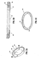
- FIG. 5A is a perspective view of the interface seal of the seal assembly in accordance with the embodiment of FIGS. 1-4;
- FIG. 5B is a cross-sectional view of the interface seal taken along
section lines 5B-5B of FIG. 5A illustrating the interface seal mount and the interface seal member of the seal assembly in accordance with the embodiment of FIGS. 1-5A; - FIG. 5C is a perspective view of the interface seal mount of the interface seal in accordance with the embodiment of FIGS. 1-5B;
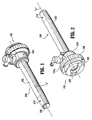
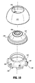
- FIGS. 6 - 7 are top and bottom perspective views of the gimbal mount of the seal assembly in accordance with the embodiment of FIGS. 1-5C;
- FIGS. 8 - 9 are cross-sectional views of the gimbal mount in accordance with the embodiment of FIGS. 1 - 7;
- FIG. 10 is a perspective view illustrating the components of the gimbal mount in accordance with the embodiment of FIGS. 1-9;
- FIGS. 11 - 13 are perspective views illustrating the range of movement of the gimbal mount within the seal housing in accordance with the embodiment of FIGS. 1-10;
- FIG. 14 is a view illustrating the cannula assembly and seal assembly accessing an internal cavity with an instrument introduced therein in accordance with the embodiment of FIGS. 1-13; and
- FIG. 15 is a side cross-sectional view of the cannula and seal assemblies illustrating a range of movement of the surgical instrument in accordance with the embodiment of FIGS. 1-14.
- The seal assembly of the present disclosure, either alone or in combination with a seal system internal to a cannula assembly, provides a substantial seal between a body cavity of a patient and the outside atmosphere before, during and after insertion of an instrument through the cannula assembly. Moreover, the seal assembly of the present invention is capable of accommodating instruments of varying diameters, e.g., from 5 mm to 15 mm, by providing a gas tight seal with each instrument when inserted. The flexibility of the present seal assembly greatly facilitates endoscopic surgery where a variety of instruments having differing diameters are often needed during a single surgical procedure.
- The seal assembly contemplates the introduction and manipulation of various types of instrumentation adapted for insertion through a trocar and/or cannula assembly while maintaining a fluid tight interface about the instrumentation to preserve the atmospheric integrity of a surgical procedure from gas and/or fluid leakage. Specifically, the seal assembly accommodates angular manipulation of the surgical instrument relative to the seal housing axis. This feature of the present disclosure desirably minimizes the entry and exit of gases and/or fluids to/from the body cavity. Examples of instrumentation include clip appliers, graspers, dissectors, retractors, staplers, laser probes, photographic devices, endoscopes and laparoscopes, tubes, and the like. Such instruments will be collectively referred to herein as "instruments or instrumentation".
- By virtue of its features, the seal assembly further defines a substantially reduced profile when assembled together and mounted to a cannula assembly. This reduced profile advantageously increases the working length of instruments introduced into the body cavity through the cannula assembly. In addition, the reduced profile permits enhanced angulation of a surgical instrument relative to the seal housing axis.
- In the following description, as is traditional the term "proximal" refers to the portion of the instrument closest to the operator while the term "distal" refers to the portion of the instrument remote from the operator.
- Referring now to the drawings, in which like reference numerals identify identical or substantially similar parts throughout the several views, FIGS. 1-2 illustrate the
seal assembly 100 of the present disclosure mounted tocannula assembly 200.Cannula assembly 200 may be any conventional cannula suitable for the intended purpose of accessing a body cavity and permit introduction of instruments therethrough.Cannula assembly 200 is particularly adapted for use in laparoscopic surgery where the peritoneal cavity is insufflated with a suitable gas, e.g., CO2, to raise the cavity wall from the internal organs therein.Cannula assembly 200 is typically used with an obturator assembly (not shown) which is a sharp pointed instrument positionable within the passageway of thecannula assembly 200. The obturator assembly is utilized to penetrate the abdominal wall and then subseauently removed from thecannula assembly 200 to permit introduction of the surgical instrumentation utilized to perform the procedure. - With reference to FIGS. 1-4,
cannula assembly 200 includescannula sleeve 202 andcannula housing 204 mounted to an end of thesleeve 202. Any means for mountingcannula sleeve 202 tocannula housing 204 are envisioned including threaded arrangements, bayonet coupling, snap-fit arrangements, adhesives, etc. Cannula sleeve 2-2 andcannula housing 204 may be integrally formed.Cannula sleeve 202 defines a longitudinal axis "a" extending along the length ofsleeve 202.Sleeve 202 further defines an internallongitudinal passage 206 dimensioned to permit passage of surgical instrumentation.Sleeve 202 definescollar 208 which is mounted tocannula housing 202 and an innertapered wall 210 adjacent thecollar 208. The sloped configuration of taperedwall 210 may assist in guiding the inserted instrument intolongitudinal passage 206. Adjacent the distal end ofcannula sleeve 202 isaperture 212 which extends through the wall of thesleeve 202.Aperture 212 permits passage of insufflation gases throughcannula sleeve 202 during the surgical procedure.Sleeve 202 may be formed of stainless steel or other rigid materials such as a polymeric material or the like.Sleeve 202 may be clear or opaque. The diameter ofsleeve 202 may vary, but, typically ranges from about 10mm to about 15 mm for use with theseal assembly 100 of the present disclosure. -
Cannula housing 204 includesport opening 214 and luer fitting 216 positioned within theport opening 214. Luer fitting 216 is adapted for connection to a supply of insufflation gaseous is conventional in the art and incorporatesvalve 218 to selectively open and close the passage of theluer fitting 216.Cannula housing 204 further includes duckbill or zeroclosure valve 220 which tapers distally and inwardly to a sealed configuration.Closure valve 220 defines slit 222 which opens to permit passage of the surgical instrumentation and closes in the absence of the instrumentation.Closure valve 220 is preferably adapted to close upon exposure to the forces exerted by the insufflation gases in the internal cavity. Other zero closure valves are also contemplated including single or multiple slit valve arrangements, trumpet valves, flapper valves, etc.Closure valve 220 rests uponinternal shelf 224 ofcannula housing 204 when assembled. -
Cannula housing 204 includes at least onelocking recess 226 preferably two recesses arranged in diametrical opposed relation. Lockingrecesses 226 serve to releasablysecure seal assembly 100 tocannula assembly 200. - With continued reference to FIGS. 1-4,
seal assembly 100 will be discussed in detail.Seal assembly 100 may be a separate component fromcannula assembly 200 and, accordingly, adapted for releasable connection to thecannula assembly 200. Alternatively,seal assembly 100 may be incorporated as part ofcannula assembly 200.Seal assembly 100 includes a seal housing, generally identified asreference numeral 102, andgimbal mount 104 which is disposed within theseal housing 102.Seal housing 102 houses the sealing components of the assembly and defines the outer valve or seal body of theseal assembly 100.Seal housing 102 defines central seal housing axis "b" which is preferably parallel to the axis "a" ofcannula sleeve 202 and, more specifically, coincident with the axis "a" of thecannula sleeve 202.Seal housing 102 incorporates three housing components, namely, first, second andthird housing components seal housing 102. Assembly ofhousing components cannula housing 204. -
First housing component 106 definesinner guide wall 112 andouter wall 114 disposed radially outwardly of theinner guide wall 112.Inner guide wall 112 definescentral passage 116 which is dimensioned to receive a surgical instrument and laterally confine the instrument withinseal housing 102. As best shown in FIG. 4,inner guide wall 112 defines sloped or taperedportion 118 adjacent its proximal end.Sloped portion 118 is obliquely arranged relative to seal housing axis "b" and extends radially inwardly relative to the seal housing axis "b" in the distal direction.Sloped portion 118 assists in guiding the inserted instrument intocentral passage 116, particularly, when the instrument is non-aligned or off-axis relative to the seal housing axis "b", or introduced at an angle relative to the seal housing axis "b".Sloped portion 118 provides more flexibility to the surgeon by removing the necessity that the instrument be substantially aligned with the seal housing axis "b" upon insertion.Inner guide wall 112 is generally cylindrical in configuration and terminates in a distal arcuate orrounded surface 120. -
Second housing component 108 includestransverse wall 122, innercylindrical wall 124 depending in a proximal direction outwardly from thetransverse wall 120 andouter wall 126 depending in a distal direction outwardly from thetransverse wall 120. Innercylindrical wall 124 is dimensioned to mate withouter wall 114 offirst housing component 106, i.e., in a manner to be positioned within the interior of theouter wall 114 in frictional relation therewith. In the alternative,outer wall 114 offirst housing component 106 may be adhered to innercylindrical wall 124 ofsecond housing component 108.Outer wall 126 defines seallopedouter surface 126a which is dimensioned for gripping engagement by the user. Extending contiguously from innercylindrical wall 124 in the distal direction is an arcuate or cup shapedgimbal wall support 124s which supportsgimbal mount 104.Transverse wall 120 further includesintermediate wall 128 of cylindrical configuration, which is disposed betweenouter wall 126 andgimbal wall support 124s. - Referring now to FIGS. 3-4, in conjunction with FIGS. 5A-5C,
seal assembly 100 further includesinterface seal 130 mountedadjacent gimbal mount 104.Interface seal 130 functions in minimizing the loss of insufflation gases throughseal assembly 100.Interface seal 130 includesinterface seal mount 132 and flexibleinterface seal member 134 secured to theseal mount 132.Seal mount 132 is preferably annular in configuration and is fabricated from a relatively rigid material such as a polymeric material or stainless steel.Interface seal member 134 is preferably fabricated from an elastomeric material having qualities to engageseal mount 104 in substantial sealed relation therewith.Interface seal member 134 definescentral aperture 136 which receives the forward or distal surface ofgimbal mount 104.Interface seal member 134 preferably extends radially inwardly and longitudinally relative to seal housing axis "b" when assembled withinseal housing 102. This configuration increases the amount of surface area ofinterface seal member 134 engaging the outer surface ofgimbal mount 104 thereby facilitating the formation and maintenance of a seal about the gimbal mount during manipulation of the instrument.Interface seal 130 further includesgasket seal 136 mounted adjacent the proximal side ofinterface seal mount 132.Gasket seal 136 is in contact with the forward or distal end ofintermediate wall 128 ofsecond housing component 108 and serves to form a seal with the intermediate wall to substantially minimize passage of fluids throughseal housing 102. -
Interface seal member 134 andgasket seal 136 are preferably monolithically formed of the desired elastomeric material. In one preferred arrangement,interface seal 130 is manufactured via a molding process. In this arrangement,interface seal mount 132 may include a plurality ofapertures 138. During molding ofinterface seal 130,apertures 138 permit the elastomeric material to communicate between the proximal and distal sides ofinterface seal mount 132 to monolithically forminterface seal member 134 andgasket seal 136. Alternatively,gasket seal 136 may be a separate component frominterface seal member 134 and may be secured to theseal mount 132 by conventional means. - With particular reference to FIG. 4,
gimbal mount 104 is accommodated within anannular space 140 defined between inner andouter walls first housing component 106.Gimbal mount 104 is mounted in a manner which permits angulation and/or rotational movement of thegimbal mount 104 relative to, or about, seal housing axis "b". Specifically,gimbal mount 104 is free to angulate relative to seal housing axis "b" through a range of motion defined within the confines ofannular space 140. The range of movement ofgimbal mount 104 will be discussed in greater detail hereinbelow.Interface seal 130 is adapted to maintain a sealing relation withgimbal mount 104 upon angular movement thereof. - Referring now to FIGS. 6-10, in conjunction with FIG. 4, the components of
gimbal mount 104 will be discussed in further detail.Gimbal mount 104 includes first andsecond gimbal housings resilient seal member 146 which is mounted between thehousings second gimbal housings seal member 146 each define a general hemispherical configuration as shown.First gimbal housing 142 is preferably seated withinsecond gimbal housing 144 and secured to thesecond gimbal housing 144 through a snap fit connection, welding, adhesives, or the like. Preferably,first gimbal housing 142 includes a plurality of mountinglegs 148 radially spaced about the outer periphery of thehousing component 134.Legs 148 define lockingsurfaces 150 which extend in general transverse relation to the axis "b" ofseal assembly 200. Similarly,second gimbal housing 144 includes a plurality of corresponding lockingdetents 152 spaced about the interior of thehousing 144. Upon insertion offirst gimbal housing 142 withinsecond gimbal housing 144, mountinglegs 148 slide along lockingdetents 152 whereby upon clearing thedetents 152, lockingsurfaces 150 of the mountinglegs 148 securely engage the lockingdetents 152 to fixfirst gimbal housing 142 withinsecond gimbal housing 144 and secureresilient seal member 146 between the components in sandwiched relation. As appreciated,first gimbal housing 142 is desirably sufficiently resilient to deflect upon insertion to permit mountinglegs 148 to clear lockingdetents 152 and return to their initial position to engage thedetents 152. - As mentioned hereinabove,
seal member 146 ofgimbal mount 104 is interposed between first andsecond gimbal housings Seal member 146 preferably comprises a resilient center material (e.g., polyisoprene or natural rubber) with first and second layers of fabric 154,156 at the respective proximal and distal surfaces of the resilient material.and impregnated with the resilient material. The fabric may be of any suitable fabric for example, a SPANDEX material containing about 20% LYCRA and about 80% NYLON available from Milliken. A suitable seal member or seal type is disclosed in commonly assignedU.S. Patent Appln. Serial No. 09/449,368, filed November 24, 1999 Seal member 146 definescentral aperture 158 for sealed reception of a surgical instrument. In a preferred arrangement,first layer 154 is arranged to extend or overlap intoaperture 158. In this manner, the fabric is positioned to engage the surgical instrument upon passage throughaperture 158 ofseal member 146 thereby protecting the resilient material defining the aperture. This advantageously minimizes the potential of piercing, penetrating or tearing of the resilient material by the instrument. Alternatively, an additional layer of fabric on the proximal surface ofseal member 146 may be superposed and arranged to drape withinaperture 158.Seal member 146 preferably includes anannular depression 160 on its distal surface, i.e., withinsecond layer 156 of fabric.Depression 160 receivesledge 162 ofsecond gimbal housing 144 to facilitate fixation ofseal member 146 between first andsecond gimbal housings - Although
seal member 146 is disclosed as an impregnated fabric arrangement, it is appreciated that other seal types may be used and still achieve the objectives of the present disclosure. Further, FIG. 8 illustratesannular depressions layer 160. One or more similar depressions may be pressed intolayer 160 to assist positioning of fabric during manufacture ofseal member 146. -
Seal assembly 100 defines a profile or height which is substantially reduced when compared to conventional cannula seal assemblies. In one preferred embodiment, the overall height ofseal assembly 100 ranges from about 0.25 inches to about 1.0 inches, preferably, about 0.65 inches. The reduced height provides more operating space above the patient, which is significant, i.e., positioned in the abdomen to access the underlying cavity. - With reference now to FIGS. 11-13, in conjunction with FIG. 4,
gimbal mount 104 moves within theannular space 140 defined between inner and outer walls 112,114 to permit angulation of the instrument relative to the seal housing axis "b" and/or rotation about the axis "b" (shown by directional arrow "d") while still maintaining a seal thereabout. During angulation of the instrument, the axis "c" of theaperture 158 ofseal member 146 intersects the axis "b" of theseal assembly 100. During angulation,gimbal mount 104 is supported betweeninner wall 112 andgimbal wall support 124s ofseal housing 102. The arcuate inner surface offirst gimbal housing 142 rides along distalarcuate surface 120 ofinner wall 112 in contacting relation therewith to permitgimbal mount 104 to swivel withinseal housing 102.Interface seal member 134 ofinterface seal 130 permits angular movement ofgimbal mount 104 while maintaining the substantial sealing relation with the outer surface ofsecond gimbal housing 144. Lubricant may be provided on the appropriate surfaces to facilitate angulation. In a preferred arrangement,gimbal mount 104 may angulate through an angle inclusive of about 30°, more preferably about 22.5° relative to seal housing axis "b". -
Seal assembly 100 may be associated with, or joined to,cannula assembly 200 in a variety of ways. In a preferred embodiment, sealhousing 102 ofseal assembly 100 andcannula housing 204 ofcannula assembly 200 are adapted to detachably engage each other, e.g., through a bayonet lock, threaded connection, or like mechanical means. In one preferred embodiment,second housing component 108 ofseal housing 102 includes a plurality ofribs 170 depending radially inwardly from outer wall 24 (FIG. 3).Ribs 170 are received within lockingrecesses 224 ofcannula housing 204, and sealassembly 100 is rotated to secure theribs 170 beneath theouter wall 226 ofcannula housing 204. Other means of joiningseal assembly 100 tocannula assembly 200 will be readily apparent to one of ordinary skill in the art. - Referring now to FIG. 15, use of the
seal assembly 100 andcannula assembly 200 in connection with introduction of a surgical instrument will be discussed.Seal assembly 100 is mounted tocannula assembly 200 which may or may not be previously introduced into an insufflated abdominal cavity. An instrument "i" is inserted intoseal assembly 100 throughpassage 116 of innercylindrical guide wall 112 inseal housing 102. If the axis of the instrument is not perfectly aligned with the axis "a" ofcannula assembly 200 or axis "b" ofseal assembly 100, then the surgical instrument will contact slopedportion 118 ofinner guide wall 112 and/or the inner surface of theseal member 146.Sloped portion 118 guides the instrument intoseal housing 102. Contact withseal member 142 can cause some deformation of theseal member 142. The instrument "i" slides along the surface of thegimbal mount 104 and/or theseal member 142 to theaperture 154. The inner sealportions d'eflning aperture 154 stretch to accommodate the instrument diameter, as necessary. The instrument "i" is advanced throughaperture 158 ofseal member 146 whereby portions of theseal member 146 defining theaperture 158 engage the instrument "i" in sealed relation therewith. The instrument "i" passes further distally into thecannula housing 204 passing throughduckbill valve 216 andcannula sleeve 202 into the body cavity. The instrument "i" may be manipulated withinseal housing 102 andcannula housing 204. Once the instrument "i" is disposed within theaperture 154, and the friction at theinterface seal member 134,gimbal mount 104 and slopedportion 118 is overcome,gimbal mount 104, swivels with respect to sealhousing 102 as the instrument is manipulated.Gimbal mount 104 is free to swivel relative tohousing 102, while allowingseal member 142 to maintain sealing engagement with the instrument "i" passed therethrough, as well as maintaining the seal around thegimbal mount 104. Preferably, theseal member 142 includes resilient material and fabric material which resists deformation of theaperture 154, as well as tearing of theseal member 142. As discussed, the instrument "i" may be rotated about seal housing axis "b" or pivoted relative to the axis "b" as desired viagimbal mount 104 to perform the surgical procedure. During these manipulations,interface seal member 134 ofinterface seal 130 maintains a sealing relation withgimbal mount 104. - While the invention has been particularly shown, and described with reference to the preferred embodiments, it will be understood by those skilled in the art that various modifications and changes in form and detail may be made therein without departing from the scope and spirit of the invention. Accordingly, modifications such as those suggested above, but not limited thereto, are to be considered within the scope of the invention.
Claims (20)
- A surgical seal assembly for use with a surgical access device, which comprises:a seal housing defining a central longitudinal axis and having a longitudinal passage dimensioned to permit passage of a surgical instrument through the seal housing;a gimbal mount disposed within the seal housing, the gimbal mount including a gimbal seal member defining an aperture for substantial sealed reception of the surgical instrument, the gimbal mount adapted for angular movement relative to the central longitudinal axis upon angulation of the surgical instrument whereby the gimbal seal member substantially maintains the seal with the surgical instrument; andan interface seal disposed within the seal housing, the interface seal a resilient interface seal member extending at least along the longitudinal axis and being in substantial contacting sealing relation with the gimbal mount, the interface seal member adapted to maintain the sealing relation with the gimbal mount upon angular movement thereof.
- The surgical seal assembly according to claim 1 wherein the interface seal includes a relatively rigid interface mount, the interface seal being mounted to the interface mount.
- The surgical seal assembly according to claim 1 or 2, wherein the interface seal includes an annular gasket seal member mounted to the mounting portion and positioned to contact an internal surface of the seal housing in substantial sealing relation therewith to form a substantial seal within the seal housing.
- The surgical seal assembly according to claim 3 wherein the interface seal member and the gasket seal member are monolithically formed.
- The surgical seal assembly according to claim 3 or 4, wherein the gasket seal member is mounted adjacent a proximal side of the mounting portion and the interface seal member is mounted adjacent a distal side of the mounting portion.
- The surgical seal assembly according to any one of the preceding claims, wherein the seal housing includes an interior wall portion at least partially defining the longitudinal passage, the interior wall portion being disposed in oblique relation relative to the longitudinal axis to taper radially inwardly along the longitudinal axis to facilitate reception of the surgical instrument.
- The surgical seal assembly according to claim 6 wherein the interior wall portion is adjacent a proximal end of the seal housing.
- The surgical seal assembly according to any one of the preceding claims, wherein the seal housing defines a height ranging from about 6 mm (0.25 inches) to about 25 mm (1.0 inches).
- The surgical seal assembly according to any one of the preceding claims, wherein the interface seal member is positioned about the gimbal mount in sliding contact relation therewith.
- The surgical seal assembly according to any one of the preceding claims, wherein the gimbal seal member includes a resilient member and a protective layer juxtaposed relative to the resilient member.
- The surgical seal assembly according to claim 10 wherein the protective layer of the gimbal seal member extends at least partially within the aperture to protect portions of the seal member defining the aperture during passage of the surgical instrument.
- The surgical seal assembly according to claim 10 or 11, wherein the protective layer includes a fabric material.
- The surgical seal assembly according to any one of the preceding claims, wherein the seal housing is adapted to be detachably mounted to a cannula assembly.
- The surgical seal assembly according to any one of the preceding claims, wherein the gimbal mount is adapted to rotate about the longitudinal axis.
- A surgical seal assembly for use with a surgical access device, which comprises:a low profile seal housing defining a central longitudinal axis and having an internal wall defining a longitudinal passage dimensioned to permit passage of a surgical instrument through the seal housing, the internal wall defining a tapered internal wall portion dimensioned to receive the surgical instrument when inserted within the longitudinal passage in angulated relation thereto;a gimbal mount disposed within the seal housing, the gimbal mount including a gimbal seal member defining an aperture for substantial sealed reception of the surgical instrument, the gimbal mount adapted for angular movement relative to the central longitudinal axis upon angulation of the surgical instrument whereby the gimbal seal member substantially maintains the sealed reception of the surgical instrument; andan interface seal disposed within the seal housing, the interface seal including an annular interface seal mount and an interface seal member mounted to the interface seal mount, the interface seal member extending at least radially inwardly relative to the longitudinal axis to contact the gimbal mount and form a substantial seal therewith, the interface seal member adapted to maintain the sealing relation with the gimbal mount upon angular movement thereof.
- The surgical seal assembly according to claim 15 wherein the seal housing defines a height ranging from about 0.25 inches to about 1.0 inches.
- The surgical seal assembly according to claim 15 or 16, wherein the seal housing defines an arcuate channel portion for at least partially accommodating the gimbal mount, the gimbal mount adapted to traverse the arcuate channel portion
- The surgical seal assembly according to claim 15, 16 or 17, wherein the seal housing is adapted to be detachably mounted to a cannula assembly.
- The surgical seal assembly according to any one of claims 15 to 18, wherein the interface seal member is dimensioned to extend along the central longitudinal axis of the seal housing.
- The surgical seal assembly according to any one of claims 15 to 19, wherein the interface seal includes an annular gasket seal member mounted to the interface mount and positioned to contact an internal surface of the seal housing in substantial sealing relation therewith to form a substantial seal within the seal housing.
Applications Claiming Priority (1)
| Application Number | Priority Date | Filing Date | Title |
|---|---|---|---|
| US11/098,966 US7931624B2 (en) | 2005-04-05 | 2005-04-05 | Introducer seal assembly with low profile gimbal seal |
Publications (2)
| Publication Number | Publication Date |
|---|---|
| EP1709918A1 true EP1709918A1 (en) | 2006-10-11 |
| EP1709918B1 EP1709918B1 (en) | 2008-10-29 |
Family
ID=36424623
Family Applications (1)
| Application Number | Title | Priority Date | Filing Date |
|---|---|---|---|
| EP06006537A Expired - Fee Related EP1709918B1 (en) | 2005-04-05 | 2006-03-29 | Introducer seal assembly with low profile gimbal seal |
Country Status (7)
| Country | Link |
|---|---|
| US (2) | US7931624B2 (en) |
| EP (1) | EP1709918B1 (en) |
| JP (2) | JP5132072B2 (en) |
| AU (1) | AU2006201289B2 (en) |
| CA (1) | CA2541556C (en) |
| DE (1) | DE602006003364D1 (en) |
| ES (1) | ES2314774T3 (en) |
Cited By (16)
| Publication number | Priority date | Publication date | Assignee | Title |
|---|---|---|---|---|
| EP1716813B1 (en) * | 2005-04-25 | 2009-12-02 | Tyco Healthcare Group Lp | Surgical portal with seal system |
| WO2010009070A1 (en) * | 2008-07-14 | 2010-01-21 | Ethicon Endo-Surgery, Inc. | Endoscopic translumenal articulatable and steerable flexible overtube |
| EP2087846A3 (en) * | 2008-01-30 | 2010-08-04 | Tyco Healthcare Group LP | Access assembly with spherical valve |
| EP2238922A1 (en) * | 2009-03-30 | 2010-10-13 | Tyco Healthcare Group LP | Surgical access apparatus with seal and closure valve assembly |
| US7918826B2 (en) | 2007-09-14 | 2011-04-05 | Ethicon Endo-Surgery, Inc. | Trocar assembly |
| US8002750B2 (en) | 2007-05-31 | 2011-08-23 | Tyco Healthcare Group Lp | Access apparatus with shallow zero closure valve |
| US8206357B2 (en) | 2009-03-26 | 2012-06-26 | Tyco Healthcare Group Lp | Articulating surgical portal apparatus with spring |
| US8551048B2 (en) | 2000-11-06 | 2013-10-08 | Covidien Lp | Surgical sealing apparatus |
| US8562520B2 (en) | 2010-10-01 | 2013-10-22 | Covidien Lp | Access port |
| US9033929B2 (en) | 2008-04-28 | 2015-05-19 | Ethicon Endo-Surgery, Inc. | Fluid removal in a surgical access device |
| USD735852S1 (en) | 2008-04-28 | 2015-08-04 | Ethicon Endo-Surgery, Inc. | Fluid remover |
| USD736926S1 (en) | 2008-04-28 | 2015-08-18 | Ethicon Endo-Sugery, Inc. | Trocar housing |
| EP3188784A4 (en) * | 2014-09-01 | 2018-05-09 | Aust Development, LLC | Catheter hubs and valves for minimizing embolic potential |
| CN108294809A (en) * | 2016-07-05 | 2018-07-20 | 江苏风和医疗器材股份有限公司 | Gasket and seal assembly and puncture outfit with it |
| US10342598B2 (en) | 2012-08-15 | 2019-07-09 | Ethicon Llc | Electrosurgical system for delivering a biphasic waveform |
| US11235111B2 (en) | 2008-04-28 | 2022-02-01 | Ethicon Llc | Surgical access device |
Families Citing this family (98)
| Publication number | Priority date | Publication date | Assignee | Title |
|---|---|---|---|---|
| US7632250B2 (en) | 2002-05-10 | 2009-12-15 | Tyco Healthcare Group Lp | Introducer seal assembly |
| CA2522766C (en) * | 2003-04-25 | 2011-07-05 | Tyco Healthcare Group Lp | Surgical hand access apparatus |
| US8241251B2 (en) | 2004-08-25 | 2012-08-14 | Tyco Healthcare Group Lp | Gel seal for a surgical trocar apparatus |
| US7582071B2 (en) * | 2005-03-28 | 2009-09-01 | Tyco Healthcare Group Lp | Introducer seal assembly |
| US8690831B2 (en) | 2008-04-25 | 2014-04-08 | Ethicon Endo-Surgery, Inc. | Gas jet fluid removal in a trocar |
| US8579807B2 (en) | 2008-04-28 | 2013-11-12 | Ethicon Endo-Surgery, Inc. | Absorbing fluids in a surgical access device |
| US8257315B2 (en) | 2006-10-11 | 2012-09-04 | Ethicon Endo-Surgery, Inc. | Trocar seal with retraction induced hinge |
| US7655004B2 (en) | 2007-02-15 | 2010-02-02 | Ethicon Endo-Surgery, Inc. | Electroporation ablation apparatus, system, and method |
| US8075572B2 (en) | 2007-04-26 | 2011-12-13 | Ethicon Endo-Surgery, Inc. | Surgical suturing apparatus |
| US8100922B2 (en) | 2007-04-27 | 2012-01-24 | Ethicon Endo-Surgery, Inc. | Curved needle suturing tool |
| US8100929B2 (en) | 2007-06-29 | 2012-01-24 | Ethicon Endo-Surgery, Inc. | Duckbill seal with fluid drainage feature |
| US8568410B2 (en) | 2007-08-31 | 2013-10-29 | Ethicon Endo-Surgery, Inc. | Electrical ablation surgical instruments |
| US8262655B2 (en) | 2007-11-21 | 2012-09-11 | Ethicon Endo-Surgery, Inc. | Bipolar forceps |
| US8579897B2 (en) | 2007-11-21 | 2013-11-12 | Ethicon Endo-Surgery, Inc. | Bipolar forceps |
| US8357123B2 (en) | 2007-09-17 | 2013-01-22 | Covidien Lp | Surgical portal with gel and fabric seal assembly |
| US20090076465A1 (en) * | 2007-09-17 | 2009-03-19 | Tyco Healthcare Group Lp | Composite seal and method for manufacturing |
| US7918827B2 (en) * | 2007-09-25 | 2011-04-05 | Tyco Healthcare Group Lp | Seal assembly for surgical access device |
| US20090112059A1 (en) | 2007-10-31 | 2009-04-30 | Nobis Rudolph H | Apparatus and methods for closing a gastrotomy |
| US8480657B2 (en) | 2007-10-31 | 2013-07-09 | Ethicon Endo-Surgery, Inc. | Detachable distal overtube section and methods for forming a sealable opening in the wall of an organ |
| US7976501B2 (en) | 2007-12-07 | 2011-07-12 | Ethicon Endo-Surgery, Inc. | Trocar seal with reduced contact area |
| US8092430B2 (en) * | 2008-03-03 | 2012-01-10 | Tyco Healthcare Group Lp | Single port device with multi-lumen cap |
| US8262680B2 (en) | 2008-03-10 | 2012-09-11 | Ethicon Endo-Surgery, Inc. | Anastomotic device |
| US8568362B2 (en) | 2008-04-28 | 2013-10-29 | Ethicon Endo-Surgery, Inc. | Surgical access device with sorbents |
| US8870747B2 (en) | 2008-04-28 | 2014-10-28 | Ethicon Endo-Surgery, Inc. | Scraping fluid removal in a surgical access device |
| US9358041B2 (en) | 2008-04-28 | 2016-06-07 | Ethicon Endo-Surgery, Llc | Wicking fluid management in a surgical access device |
| US7981092B2 (en) | 2008-05-08 | 2011-07-19 | Ethicon Endo-Surgery, Inc. | Vibratory trocar |
| US8652150B2 (en) | 2008-05-30 | 2014-02-18 | Ethicon Endo-Surgery, Inc. | Multifunction surgical device |
| US8679003B2 (en) | 2008-05-30 | 2014-03-25 | Ethicon Endo-Surgery, Inc. | Surgical device and endoscope including same |
| US8317806B2 (en) | 2008-05-30 | 2012-11-27 | Ethicon Endo-Surgery, Inc. | Endoscopic suturing tension controlling and indication devices |
| US8114072B2 (en) | 2008-05-30 | 2012-02-14 | Ethicon Endo-Surgery, Inc. | Electrical ablation device |
| US8771260B2 (en) | 2008-05-30 | 2014-07-08 | Ethicon Endo-Surgery, Inc. | Actuating and articulating surgical device |
| US8070759B2 (en) | 2008-05-30 | 2011-12-06 | Ethicon Endo-Surgery, Inc. | Surgical fastening device |
| US8906035B2 (en) | 2008-06-04 | 2014-12-09 | Ethicon Endo-Surgery, Inc. | Endoscopic drop off bag |
| US8403926B2 (en) | 2008-06-05 | 2013-03-26 | Ethicon Endo-Surgery, Inc. | Manually articulating devices |
| US8361112B2 (en) | 2008-06-27 | 2013-01-29 | Ethicon Endo-Surgery, Inc. | Surgical suture arrangement |
| US8888792B2 (en) | 2008-07-14 | 2014-11-18 | Ethicon Endo-Surgery, Inc. | Tissue apposition clip application devices and methods |
| US8262563B2 (en) | 2008-07-14 | 2012-09-11 | Ethicon Endo-Surgery, Inc. | Endoscopic translumenal articulatable steerable overtube |
| US8211125B2 (en) * | 2008-08-15 | 2012-07-03 | Ethicon Endo-Surgery, Inc. | Sterile appliance delivery device for endoscopic procedures |
| US8529563B2 (en) | 2008-08-25 | 2013-09-10 | Ethicon Endo-Surgery, Inc. | Electrical ablation devices |
| US8241204B2 (en) | 2008-08-29 | 2012-08-14 | Ethicon Endo-Surgery, Inc. | Articulating end cap |
| US8480689B2 (en) | 2008-09-02 | 2013-07-09 | Ethicon Endo-Surgery, Inc. | Suturing device |
| US8409200B2 (en) | 2008-09-03 | 2013-04-02 | Ethicon Endo-Surgery, Inc. | Surgical grasping device |
| US8114119B2 (en) | 2008-09-09 | 2012-02-14 | Ethicon Endo-Surgery, Inc. | Surgical grasping device |
| US8337394B2 (en) | 2008-10-01 | 2012-12-25 | Ethicon Endo-Surgery, Inc. | Overtube with expandable tip |
| US20100114033A1 (en) * | 2008-11-06 | 2010-05-06 | Tyco Healthcare Group Lp | Surgical access device |
| US8157834B2 (en) | 2008-11-25 | 2012-04-17 | Ethicon Endo-Surgery, Inc. | Rotational coupling device for surgical instrument with flexible actuators |
| US8172772B2 (en) | 2008-12-11 | 2012-05-08 | Ethicon Endo-Surgery, Inc. | Specimen retrieval device |
| US8828031B2 (en) | 2009-01-12 | 2014-09-09 | Ethicon Endo-Surgery, Inc. | Apparatus for forming an anastomosis |
| US8361066B2 (en) | 2009-01-12 | 2013-01-29 | Ethicon Endo-Surgery, Inc. | Electrical ablation devices |
| US8252057B2 (en) | 2009-01-30 | 2012-08-28 | Ethicon Endo-Surgery, Inc. | Surgical access device |
| US9226772B2 (en) | 2009-01-30 | 2016-01-05 | Ethicon Endo-Surgery, Inc. | Surgical device |
| US8037591B2 (en) | 2009-02-02 | 2011-10-18 | Ethicon Endo-Surgery, Inc. | Surgical scissors |
| US8070730B2 (en) * | 2009-03-27 | 2011-12-06 | Tyco Healthcare Group Lp | Integral insufflation valve |
| US8206358B2 (en) | 2009-05-06 | 2012-06-26 | Tyco Healthcare Group Lp | Ring and seal for trocar |
| US8721536B2 (en) * | 2009-07-28 | 2014-05-13 | Trinity Orthopedics, Llc | Arcuate surgical guidance system and methods |
| US20110098704A1 (en) | 2009-10-28 | 2011-04-28 | Ethicon Endo-Surgery, Inc. | Electrical ablation devices |
| US8608652B2 (en) | 2009-11-05 | 2013-12-17 | Ethicon Endo-Surgery, Inc. | Vaginal entry surgical devices, kit, system, and method |
| US8496574B2 (en) | 2009-12-17 | 2013-07-30 | Ethicon Endo-Surgery, Inc. | Selectively positionable camera for surgical guide tube assembly |
| US8926508B2 (en) * | 2009-12-17 | 2015-01-06 | Covidien Lp | Access assembly with dual anchor and seal capabilities |
| US8353487B2 (en) | 2009-12-17 | 2013-01-15 | Ethicon Endo-Surgery, Inc. | User interface support devices for endoscopic surgical instruments |
| US9028483B2 (en) | 2009-12-18 | 2015-05-12 | Ethicon Endo-Surgery, Inc. | Surgical instrument comprising an electrode |
| US8506564B2 (en) | 2009-12-18 | 2013-08-13 | Ethicon Endo-Surgery, Inc. | Surgical instrument comprising an electrode |
| US9005198B2 (en) | 2010-01-29 | 2015-04-14 | Ethicon Endo-Surgery, Inc. | Surgical instrument comprising an electrode |
| US8864659B2 (en) | 2010-11-23 | 2014-10-21 | Covidien Lp | Seal anchor for use in surgical procedures |
| US10092291B2 (en) | 2011-01-25 | 2018-10-09 | Ethicon Endo-Surgery, Inc. | Surgical instrument with selectively rigidizable features |
| US9254169B2 (en) | 2011-02-28 | 2016-02-09 | Ethicon Endo-Surgery, Inc. | Electrical ablation devices and methods |
| US9233241B2 (en) | 2011-02-28 | 2016-01-12 | Ethicon Endo-Surgery, Inc. | Electrical ablation devices and methods |
| US9314620B2 (en) | 2011-02-28 | 2016-04-19 | Ethicon Endo-Surgery, Inc. | Electrical ablation devices and methods |
| US9049987B2 (en) | 2011-03-17 | 2015-06-09 | Ethicon Endo-Surgery, Inc. | Hand held surgical device for manipulating an internal magnet assembly within a patient |
| AU2012356750B2 (en) * | 2011-12-23 | 2016-06-30 | EON Surgical Ltd. | Laparoscopic seal bridge |
| US9146576B2 (en) * | 2012-02-06 | 2015-09-29 | Arthrex, Inc. | Arthroscope rotation mechanisms and methods of endoscopic rotation |
| US8986199B2 (en) | 2012-02-17 | 2015-03-24 | Ethicon Endo-Surgery, Inc. | Apparatus and methods for cleaning the lens of an endoscope |
| WO2013167717A1 (en) * | 2012-05-09 | 2013-11-14 | EON Surgical Ltd. | Laparoscopic port |
| US9427255B2 (en) | 2012-05-14 | 2016-08-30 | Ethicon Endo-Surgery, Inc. | Apparatus for introducing a steerable camera assembly into a patient |
| US9486242B2 (en) | 2012-05-15 | 2016-11-08 | Covidien Lp | Surgical access device including gimbal seal with self-centering mechanism |
| US10299778B2 (en) | 2012-05-15 | 2019-05-28 | Covidien Lp | Surgical access device including gimbal mount cooperating with bellows |
| US9078662B2 (en) | 2012-07-03 | 2015-07-14 | Ethicon Endo-Surgery, Inc. | Endoscopic cap electrode and method for using the same |
| US9247956B2 (en) * | 2012-07-19 | 2016-02-02 | Covidien Lp | Method and structure for selectively locking portions of a seal assembly |
| US9545290B2 (en) | 2012-07-30 | 2017-01-17 | Ethicon Endo-Surgery, Inc. | Needle probe guide |
| US9572623B2 (en) | 2012-08-02 | 2017-02-21 | Ethicon Endo-Surgery, Inc. | Reusable electrode and disposable sheath |
| US10314649B2 (en) | 2012-08-02 | 2019-06-11 | Ethicon Endo-Surgery, Inc. | Flexible expandable electrode and method of intraluminal delivery of pulsed power |
| CA2879636C (en) * | 2012-09-28 | 2020-06-09 | Covidien Lp | Optical trocar visualization system and apparatus |
| US9901372B2 (en) | 2013-02-21 | 2018-02-27 | Covidien Lp | Surgical access device including gimbal mount cooperating with bellows attached to proximal wall of seal housing |
| US10098527B2 (en) | 2013-02-27 | 2018-10-16 | Ethidcon Endo-Surgery, Inc. | System for performing a minimally invasive surgical procedure |
| EP3166515B1 (en) | 2014-07-08 | 2018-09-12 | Applied Medical Resources Corporation | Highly responsive instrument seal |
| US10086164B2 (en) * | 2015-09-08 | 2018-10-02 | Jeng-Yu Chou | Medical joint and check valve module thereof |
| CN106037896B (en) * | 2016-07-05 | 2020-02-04 | 江苏风和医疗器材股份有限公司 | Sealing gasket, sealing assembly with same and puncture outfit |
| US10874426B2 (en) | 2017-02-10 | 2020-12-29 | Covidien Lp | Seal assembly with integral filter and evacuation port |
| DE102017103545A1 (en) | 2017-02-21 | 2018-08-23 | Karl Storz Se & Co. Kg | Probe setup for a resectoscope or other micro-invasive instrument |
| US11576560B2 (en) * | 2017-10-19 | 2023-02-14 | Ottek Ltd. | Hollow probe with sleeve |
| US11357542B2 (en) | 2019-06-21 | 2022-06-14 | Covidien Lp | Valve assembly and retainer for surgical access assembly |
| US11259840B2 (en) * | 2019-06-21 | 2022-03-01 | Covidien Lp | Valve assemblies for surgical access assemblies |
| US11812991B2 (en) | 2019-10-18 | 2023-11-14 | Covidien Lp | Seal assemblies for surgical access assemblies |
| US20210275223A1 (en) * | 2020-03-06 | 2021-09-09 | Covidien Lp | Snap-fit transvaginal occluder |
| US11642153B2 (en) | 2020-03-19 | 2023-05-09 | Covidien Lp | Instrument seal for surgical access assembly |
| US11541218B2 (en) | 2020-03-20 | 2023-01-03 | Covidien Lp | Seal assembly for a surgical access assembly and method of manufacturing the same |
| US11446058B2 (en) | 2020-03-27 | 2022-09-20 | Covidien Lp | Fixture device for folding a seal member |
| US11717321B2 (en) | 2020-04-24 | 2023-08-08 | Covidien Lp | Access assembly with retention mechanism |
Citations (7)
| Publication number | Priority date | Publication date | Assignee | Title |
|---|---|---|---|---|
| DE1893771U (en) * | 1963-10-07 | 1964-05-27 | Bernhard Gollenbeck | COUPLING FOR HYDRAULIC RIVETING DEVICE |
| US5209737A (en) * | 1991-07-18 | 1993-05-11 | Applied Medical Resources, Inc. | Lever actuated septum seal |
| US5211370A (en) * | 1992-01-06 | 1993-05-18 | Powers Ronald J | Variable orifice sealing valve |
| US5385553A (en) * | 1991-07-18 | 1995-01-31 | Applied Medical Resources Corporation | Trocar with floating septum seal |
| US5779697A (en) * | 1997-05-28 | 1998-07-14 | Linvatec Corporation | Arthroscopic cannula with fluid seals |
| WO2003094760A2 (en) * | 2002-05-10 | 2003-11-20 | Tyco Healthcare Group Lp | Introducer seal assembly |
| US20040204682A1 (en) * | 2000-11-06 | 2004-10-14 | Smith Robert C. | Surgical sealing apparatus |
Family Cites Families (98)
| Publication number | Priority date | Publication date | Assignee | Title |
|---|---|---|---|---|
| US538553A (en) * | 1895-04-30 | Schmidt | ||
| US3421509A (en) | 1965-12-17 | 1969-01-14 | John M Fiore | Urethral catheter |
| US3565078A (en) | 1969-04-25 | 1971-02-23 | Bard Inc C R | Quick disconnect catheter coupling |
| US3907310A (en) | 1971-02-25 | 1975-09-23 | Gas Dev Corp | Floating seal construction |
| US3853127A (en) | 1973-04-03 | 1974-12-10 | R Spademan | Elastic sealing member |
| US3994287A (en) | 1974-07-01 | 1976-11-30 | Centre De Recherche Industrielle Du Quebec | Trocar |
| GB1482857A (en) | 1974-09-10 | 1977-08-17 | Wolf Gmbh Richard | Trocar guides |
| US4000739A (en) | 1975-07-09 | 1977-01-04 | Cordis Corporation | Hemostasis cannula |
| US4112932A (en) | 1977-02-24 | 1978-09-12 | Chiulli Robert D | Laparoscopic cannula |
| JPS6034241Y2 (en) | 1977-04-25 | 1985-10-12 | オリンパス光学工業株式会社 | Endoscope passage sealing device |
| US4177814A (en) | 1978-01-18 | 1979-12-11 | KLI, Incorporated | Self-sealing cannula |
| DE2817102C2 (en) | 1978-04-19 | 1985-01-24 | Dr. Eduard Fresenius, Chemisch-pharmazeutische Industrie KG, 6380 Bad Homburg | Connector for plastic cannulas or venous catheters |
| US4173350A (en) | 1978-08-07 | 1979-11-06 | Roy E. Roth Company | Floating seals |
| US4177997A (en) | 1978-12-08 | 1979-12-11 | General Motors Corporation | Floating seal |
| CA1136665A (en) | 1979-11-27 | 1982-11-30 | Ernst A. Kronenberg | Shaft seal of the type incorporating a sealing flange |
| ATE3242T1 (en) | 1979-12-01 | 1983-05-15 | Intermedicat Gmbh | CATHETER CONNECTION HEAD WITH AT LEAST ONE CHANNEL IN A BASIC BODY. |
| US4240335A (en) | 1979-12-13 | 1980-12-23 | Honeywell Inc. | Floating seal for fluidic devices |
| US4386756A (en) | 1980-03-27 | 1983-06-07 | Valve Concepts International | Self centering floating metal seal for a ball valve |
| US4334688A (en) | 1980-05-08 | 1982-06-15 | The United States Of America As Represented By The Secretary Of The Navy | Fluid lubricated floating bushing seal |
| DE3042229C2 (en) | 1980-11-08 | 1983-10-27 | B. Braun Melsungen Ag, 3508 Melsungen | Insertion device for inserting elongated objects into blood vessels |
| US4338689A (en) | 1980-12-05 | 1982-07-13 | Kaiser Aerospace & Electronics Corporation | Self-aligning valve assembly |
| US4430081A (en) | 1981-01-06 | 1984-02-07 | Cook, Inc. | Hemostasis sheath |
| US4448449A (en) | 1981-05-04 | 1984-05-15 | Halling Horace P | Flexible piping joint and method of forming same |
| US4383692A (en) | 1981-06-02 | 1983-05-17 | Murray Corporation | Grommet seal |
| US4464178A (en) | 1981-11-25 | 1984-08-07 | Dalton Michael J | Method and apparatus for administration of fluids |
| US4447237A (en) | 1982-05-07 | 1984-05-08 | Dow Corning Corporation | Valving slit construction and cooperating assembly for penetrating the same |
| DE3217118C1 (en) | 1982-05-07 | 1983-08-25 | Busak + Luyken GmbH & Co, 7000 Stuttgart | Seal arrangement for shafts |
| EP0113520A2 (en) | 1982-12-06 | 1984-07-18 | Vance Products Incorporated | Nephroscopy cannula |
| US4601710B1 (en) | 1983-08-24 | 1998-05-05 | United States Surgical Corp | Trocar assembly |
| US4655752A (en) | 1983-10-24 | 1987-04-07 | Acufex Microsurgical, Inc. | Surgical cannula |
| US4653477A (en) | 1984-09-13 | 1987-03-31 | Olympus Optical Co., Ltd. | Endoscope forceps stopcock |
| US4553760A (en) | 1984-11-19 | 1985-11-19 | Caterpillar Tractor Co. | Flexible seal for a spherical joint |
| JPS61154679A (en) | 1984-12-28 | 1986-07-14 | テルモ株式会社 | Medical instrument |
| JPH0211655Y2 (en) | 1985-03-29 | 1990-03-27 | ||
| US4705511A (en) | 1985-05-13 | 1987-11-10 | Bipore, Inc. | Introducer sheath assembly |
| US4626245A (en) | 1985-08-30 | 1986-12-02 | Cordis Corporation | Hemostatis valve comprising an elastomeric partition having opposed intersecting slits |
| GB8527646D0 (en) | 1985-11-08 | 1985-12-11 | Cox J A | Devices for sampling drainage |
| US4588195A (en) | 1985-11-22 | 1986-05-13 | Dana Corporation | Floating lip seal assembly with convoluted flexible section |
| US4654030A (en) | 1986-02-24 | 1987-03-31 | Endotherapeutics | Trocar |
| DE3616689C1 (en) | 1986-05-16 | 1987-11-19 | Mueller Heinz Konrad Prof Dr I | poetry |
| US4795439A (en) * | 1986-06-06 | 1989-01-03 | Edward Weck Incorporated | Spiral multi-lumen catheter |
| GB8618253D0 (en) | 1986-07-25 | 1986-09-03 | Wallace Ltd H G | Intermittent administration of therapeutic substance |
| US4723550A (en) | 1986-11-10 | 1988-02-09 | Cordis Corporation | Leakproof hemostasis valve with single valve member |
| EP0312219B1 (en) | 1987-10-13 | 1994-12-14 | United States Surgical Corporation | Trocar assembly |
| US4909798A (en) | 1987-11-12 | 1990-03-20 | Daig Corporation | Universal hemostasis cannula |
| JPH0198368U (en) | 1987-12-23 | 1989-06-30 | ||
| US5053016A (en) | 1987-12-31 | 1991-10-01 | United States Surgical Corporation | Valve seat for an insufflation cannula assembly |
| US4943280A (en) | 1987-12-31 | 1990-07-24 | United States Surgical Corporaiton | Self-seating flapper valve for an insufflation cannula assembly |
| US4842591A (en) | 1988-01-21 | 1989-06-27 | Luther Ronald B | Connector with one-way septum valve, and assembly |
| US4857062A (en) | 1988-03-09 | 1989-08-15 | Medical Parameters, Inc. | Catheter introducer valve |
| US4869717A (en) | 1988-04-25 | 1989-09-26 | Adair Edwin Lloyd | Gas insufflation needle with instrument port |
| US4844484A (en) | 1988-06-28 | 1989-07-04 | Dana Corporation | Floating lip seal with reinforced flexible portion |
| JPH0266816A (en) | 1988-08-31 | 1990-03-06 | Yazaki Corp | Grommet |
| US5000745A (en) | 1988-11-18 | 1991-03-19 | Edward Weck Incorporated | Hemostatis valve |
| US4932633A (en) | 1988-11-21 | 1990-06-12 | Schneider-Shiley (U.S.A.) Inc. | Hemostasis valve |
| DE3909609A1 (en) | 1989-03-23 | 1990-10-04 | Freudenberg Carl Fa | SLEEVE RUBBER SPRING |
| US5002557A (en) | 1989-04-06 | 1991-03-26 | Hasson Harrith M | Laparoscopic cannula |
| US4998740A (en) | 1989-09-29 | 1991-03-12 | Rockwell International Corporation | Face seal assembly |
| US5104383A (en) | 1989-10-17 | 1992-04-14 | United States Surgical Corporation | Trocar adapter seal and method of use |
| US5038756A (en) | 1989-10-30 | 1991-08-13 | Storz Instrument Company | Needle interface boot for ultrasonic surgical instrument |
| US5041095A (en) | 1989-12-22 | 1991-08-20 | Cordis Corporation | Hemostasis valve |
| US5053014A (en) | 1990-02-01 | 1991-10-01 | Critikon, Inc. | Catheter with controlled valve |
| US5015000A (en) | 1990-06-28 | 1991-05-14 | Moog Controls, Inc. | Floating seal arrangement |
| US5073169A (en) | 1990-10-02 | 1991-12-17 | Steve Raiken | Trocar support |
| US5137520A (en) | 1991-04-24 | 1992-08-11 | Wayne Maxson | Cannula skirt |
| US5290304A (en) | 1991-05-14 | 1994-03-01 | Ingram S. Chodorow | Trocar system |
| US5180373A (en) | 1991-06-07 | 1993-01-19 | United States Surgical Corporation | Valve system for introducing objects into anatomical body portions |
| EP0600895B1 (en) | 1991-08-30 | 1999-08-04 | Origin Medsystems, Inc. | Trocar with multiple converters and detachable obturator |
| US5273545A (en) | 1991-10-15 | 1993-12-28 | Apple Medical Corporation | Endoscopic cannula with tricuspid leaf valve |
| US5167636A (en) | 1991-10-24 | 1992-12-01 | Mectra Labs, Inc. | Cannula sealing mechanism |
| US5299813A (en) | 1991-12-20 | 1994-04-05 | Ingersoll-Dresser Pump Company | Floating seal ring |
| US5334164A (en) | 1992-01-03 | 1994-08-02 | United States Surgical Corporation | Variable interior dimension cannula assembly |
| US5226891A (en) | 1992-04-07 | 1993-07-13 | Applied Medical Resources | Seal protection apparatus |
| US5375588A (en) | 1992-08-17 | 1994-12-27 | Yoon; Inbae | Method and apparatus for use in endoscopic procedures |
| US5342315A (en) | 1993-04-12 | 1994-08-30 | Ethicon, Inc. | Trocar seal/protector assemblies |
| CA2126150C (en) * | 1993-07-14 | 2005-02-22 | David T. Green | Seal assembly for accommodating introduction of surgical instruments |
| JPH07228208A (en) | 1994-02-17 | 1995-08-29 | Sumitomo Wiring Syst Ltd | Grommet |
| US5603702A (en) | 1994-08-08 | 1997-02-18 | United States Surgical Corporation | Valve system for cannula assembly |
| US5614136A (en) * | 1995-03-02 | 1997-03-25 | Scimed Life Systems, Inc. | Process to form dimensionally variable tubular members for use in catheter procedures |
| GB2298905A (en) | 1995-03-11 | 1996-09-18 | Microsurgical Equipment Ltd | Displaceable seal system for trocars |
| US5839639A (en) | 1995-08-17 | 1998-11-24 | Lasersurge, Inc. | Collapsible anvil assembly and applicator instrument |
| US5820600A (en) * | 1996-05-14 | 1998-10-13 | Innerdyne, Inc. | Adjustable introducer valve |
| US5792113A (en) | 1996-12-12 | 1998-08-11 | Ethicon Endo-Surgerym Inc. | Universal seal for a trocar |
| US5865817A (en) | 1997-04-29 | 1999-02-02 | Moenning; Stephen P. | Apparatus and method for securing a medical instrument to a cannula of a trocar assembly |
| US6440063B1 (en) * | 1997-04-30 | 2002-08-27 | University Of Massachusetts | Surgical access port and laparoscopic surgical method |
| EP1015049B1 (en) | 1997-05-28 | 2004-08-18 | United States Surgical Corporation | Trocar seal system |
| US6231565B1 (en) | 1997-06-18 | 2001-05-15 | United States Surgical Corporation | Robotic arm DLUs for performing surgical tasks |
| US6113106A (en) | 1997-11-03 | 2000-09-05 | Freudenberg-Nok General Partnership | Gimballed mechanical face seal |
| JP3047232B1 (en) * | 1999-04-05 | 2000-05-29 | 株式会社三輝 | Hose connector |
| JP2001137253A (en) * | 1999-11-12 | 2001-05-22 | Olympus Optical Co Ltd | Trocar |
| US6551270B1 (en) | 2000-08-30 | 2003-04-22 | Snowden Pencer, Inc. | Dual lumen access port |
| US6663614B1 (en) * | 2000-11-06 | 2003-12-16 | Advanced Cardiovascular Systems, Inc. | Catheter shaft having variable thickness layers and method of making |
| US20040066008A1 (en) | 2002-10-04 | 2004-04-08 | Smith Robert C. | Introducer seal assembly |
| JP2004195037A (en) * | 2002-12-20 | 2004-07-15 | Hakko Co Ltd | Insertion port of medical treatment instrument |
| US7582071B2 (en) | 2005-03-28 | 2009-09-01 | Tyco Healthcare Group Lp | Introducer seal assembly |
| US20060247586A1 (en) | 2005-04-08 | 2006-11-02 | Voegele James W | Intra-abdominal storage device |
| EP3245941B1 (en) | 2007-03-30 | 2019-05-01 | Covidien LP | Laparoscopic port assembly |
| US8187178B2 (en) | 2007-06-05 | 2012-05-29 | Atropos Limited | Instrument access device |
-
2005
- 2005-04-05 US US11/098,966 patent/US7931624B2/en active Active
-
2006
- 2006-03-28 AU AU2006201289A patent/AU2006201289B2/en not_active Ceased
- 2006-03-29 DE DE602006003364T patent/DE602006003364D1/en active Active
- 2006-03-29 EP EP06006537A patent/EP1709918B1/en not_active Expired - Fee Related
- 2006-03-29 ES ES06006537T patent/ES2314774T3/en active Active
- 2006-03-31 JP JP2006100841A patent/JP5132072B2/en not_active Expired - Fee Related
- 2006-03-31 CA CA2541556A patent/CA2541556C/en not_active Expired - Fee Related
-
2011
- 2011-03-18 US US13/050,987 patent/US8696635B2/en active Active
- 2011-12-15 JP JP2011274967A patent/JP2012075929A/en not_active Withdrawn
Patent Citations (7)
| Publication number | Priority date | Publication date | Assignee | Title |
|---|---|---|---|---|
| DE1893771U (en) * | 1963-10-07 | 1964-05-27 | Bernhard Gollenbeck | COUPLING FOR HYDRAULIC RIVETING DEVICE |
| US5209737A (en) * | 1991-07-18 | 1993-05-11 | Applied Medical Resources, Inc. | Lever actuated septum seal |
| US5385553A (en) * | 1991-07-18 | 1995-01-31 | Applied Medical Resources Corporation | Trocar with floating septum seal |
| US5211370A (en) * | 1992-01-06 | 1993-05-18 | Powers Ronald J | Variable orifice sealing valve |
| US5779697A (en) * | 1997-05-28 | 1998-07-14 | Linvatec Corporation | Arthroscopic cannula with fluid seals |
| US20040204682A1 (en) * | 2000-11-06 | 2004-10-14 | Smith Robert C. | Surgical sealing apparatus |
| WO2003094760A2 (en) * | 2002-05-10 | 2003-11-20 | Tyco Healthcare Group Lp | Introducer seal assembly |
Cited By (22)
| Publication number | Priority date | Publication date | Assignee | Title |
|---|---|---|---|---|
| US8551048B2 (en) | 2000-11-06 | 2013-10-08 | Covidien Lp | Surgical sealing apparatus |
| EP1716813B1 (en) * | 2005-04-25 | 2009-12-02 | Tyco Healthcare Group Lp | Surgical portal with seal system |
| US8353875B2 (en) | 2007-05-31 | 2013-01-15 | Covidien Lp | Access apparatus with shallow zero closure valve |
| US8002750B2 (en) | 2007-05-31 | 2011-08-23 | Tyco Healthcare Group Lp | Access apparatus with shallow zero closure valve |
| US7918826B2 (en) | 2007-09-14 | 2011-04-05 | Ethicon Endo-Surgery, Inc. | Trocar assembly |
| EP2087846A3 (en) * | 2008-01-30 | 2010-08-04 | Tyco Healthcare Group LP | Access assembly with spherical valve |
| AU2009200106B2 (en) * | 2008-01-30 | 2014-02-20 | Covidien Lp | Access assembly with spherical valve |
| US8579860B2 (en) | 2008-01-30 | 2013-11-12 | Covidien Lp | Access assembly with spherical valve |
| US8118783B2 (en) | 2008-01-30 | 2012-02-21 | Tyco Healthcare Group Lp | Access assembly with spherical valve |
| USD735852S1 (en) | 2008-04-28 | 2015-08-04 | Ethicon Endo-Surgery, Inc. | Fluid remover |
| US9033929B2 (en) | 2008-04-28 | 2015-05-19 | Ethicon Endo-Surgery, Inc. | Fluid removal in a surgical access device |
| USD736926S1 (en) | 2008-04-28 | 2015-08-18 | Ethicon Endo-Sugery, Inc. | Trocar housing |
| US9827383B2 (en) | 2008-04-28 | 2017-11-28 | Ethicon Llc | Surgical access device |
| US11235111B2 (en) | 2008-04-28 | 2022-02-01 | Ethicon Llc | Surgical access device |
| WO2010009070A1 (en) * | 2008-07-14 | 2010-01-21 | Ethicon Endo-Surgery, Inc. | Endoscopic translumenal articulatable and steerable flexible overtube |
| US8206357B2 (en) | 2009-03-26 | 2012-06-26 | Tyco Healthcare Group Lp | Articulating surgical portal apparatus with spring |
| US7938804B2 (en) | 2009-03-30 | 2011-05-10 | Tyco Healthcare Group Lp | Surgical access apparatus with seal and closure valve assembly |
| EP2238922A1 (en) * | 2009-03-30 | 2010-10-13 | Tyco Healthcare Group LP | Surgical access apparatus with seal and closure valve assembly |
| US8562520B2 (en) | 2010-10-01 | 2013-10-22 | Covidien Lp | Access port |
| US10342598B2 (en) | 2012-08-15 | 2019-07-09 | Ethicon Llc | Electrosurgical system for delivering a biphasic waveform |
| EP3188784A4 (en) * | 2014-09-01 | 2018-05-09 | Aust Development, LLC | Catheter hubs and valves for minimizing embolic potential |
| CN108294809A (en) * | 2016-07-05 | 2018-07-20 | 江苏风和医疗器材股份有限公司 | Gasket and seal assembly and puncture outfit with it |
Also Published As
| Publication number | Publication date |
|---|---|
| US7931624B2 (en) | 2011-04-26 |
| CA2541556C (en) | 2014-07-22 |
| JP2006289082A (en) | 2006-10-26 |
| AU2006201289B2 (en) | 2011-11-24 |
| ES2314774T3 (en) | 2009-03-16 |
| DE602006003364D1 (en) | 2008-12-11 |
| CA2541556A1 (en) | 2006-10-05 |
| US20060224120A1 (en) | 2006-10-05 |
| JP5132072B2 (en) | 2013-01-30 |
| US8696635B2 (en) | 2014-04-15 |
| AU2006201289A1 (en) | 2006-10-19 |
| JP2012075929A (en) | 2012-04-19 |
| US20110201891A1 (en) | 2011-08-18 |
| EP1709918B1 (en) | 2008-10-29 |
Similar Documents
| Publication | Publication Date | Title |
|---|---|---|
| EP1709918B1 (en) | Introducer seal assembly with low profile gimbal seal | |
| US7632250B2 (en) | Introducer seal assembly | |
| EP1997446B1 (en) | Access apparatus with shallow zero closure valve | |
| US11540821B2 (en) | Surgical access device including gimbal mount cooperating with bellows | |
| EP2042114B1 (en) | Seal assembly for surgical access device | |
| EP2263575B1 (en) | Introducer seal assembly | |
| AU2008261180B2 (en) | Introducer seal assembly | |
| AU2011205165A1 (en) | Introducer seal assembly |
Legal Events
| Date | Code | Title | Description |
|---|---|---|---|
| PUAI | Public reference made under article 153(3) epc to a published international application that has entered the european phase |
Free format text: ORIGINAL CODE: 0009012 |
|
| AK | Designated contracting states |
Kind code of ref document: A1 Designated state(s): AT BE BG CH CY CZ DE DK EE ES FI FR GB GR HU IE IS IT LI LT LU LV MC NL PL PT RO SE SI SK TR |
|
| AX | Request for extension of the european patent |
Extension state: AL BA HR MK YU |
|
| 17P | Request for examination filed |
Effective date: 20070315 |
|
| 17Q | First examination report despatched |
Effective date: 20070413 |
|
| AKX | Designation fees paid |
Designated state(s): DE ES FR GB IE IT |
|
| GRAP | Despatch of communication of intention to grant a patent |
Free format text: ORIGINAL CODE: EPIDOSNIGR1 |
|
| GRAS | Grant fee paid |
Free format text: ORIGINAL CODE: EPIDOSNIGR3 |
|
| GRAA | (expected) grant |
Free format text: ORIGINAL CODE: 0009210 |
|
| AK | Designated contracting states |
Kind code of ref document: B1 Designated state(s): DE ES FR GB IE IT |
|
| REG | Reference to a national code |
Ref country code: GB Ref legal event code: FG4D |
|
| RAP2 | Party data changed (patent owner data changed or rights of a patent transferred) |
Owner name: TYCO HEALTHCARE GROUP LP |
|
| REG | Reference to a national code |
Ref country code: IE Ref legal event code: FG4D |
|
| REF | Corresponds to: |
Ref document number: 602006003364 Country of ref document: DE Date of ref document: 20081211 Kind code of ref document: P |
|
| REG | Reference to a national code |
Ref country code: ES Ref legal event code: FG2A Ref document number: 2314774 Country of ref document: ES Kind code of ref document: T3 |
|
| PLBE | No opposition filed within time limit |
Free format text: ORIGINAL CODE: 0009261 |
|
| STAA | Information on the status of an ep patent application or granted ep patent |
Free format text: STATUS: NO OPPOSITION FILED WITHIN TIME LIMIT |
|
| 26N | No opposition filed |
Effective date: 20090730 |
|
| PGFP | Annual fee paid to national office [announced via postgrant information from national office to epo] |
Ref country code: IT Payment date: 20120323 Year of fee payment: 7 |
|
| PGFP | Annual fee paid to national office [announced via postgrant information from national office to epo] |
Ref country code: ES Payment date: 20130326 Year of fee payment: 8 |
|
| PG25 | Lapsed in a contracting state [announced via postgrant information from national office to epo] |
Ref country code: IT Free format text: LAPSE BECAUSE OF NON-PAYMENT OF DUE FEES Effective date: 20140329 |
|
| REG | Reference to a national code |
Ref country code: ES Ref legal event code: FD2A Effective date: 20150828 |
|
| PG25 | Lapsed in a contracting state [announced via postgrant information from national office to epo] |
Ref country code: ES Free format text: LAPSE BECAUSE OF NON-PAYMENT OF DUE FEES Effective date: 20140330 |
|
| REG | Reference to a national code |
Ref country code: FR Ref legal event code: PLFP Year of fee payment: 11 |
|
| REG | Reference to a national code |
Ref country code: FR Ref legal event code: PLFP Year of fee payment: 12 |
|
| REG | Reference to a national code |
Ref country code: FR Ref legal event code: PLFP Year of fee payment: 13 |
|
| PGFP | Annual fee paid to national office [announced via postgrant information from national office to epo] |
Ref country code: IE Payment date: 20200227 Year of fee payment: 15 |
|
| PGFP | Annual fee paid to national office [announced via postgrant information from national office to epo] |
Ref country code: GB Payment date: 20210219 Year of fee payment: 16 |
|
| PG25 | Lapsed in a contracting state [announced via postgrant information from national office to epo] |
Ref country code: IE Free format text: LAPSE BECAUSE OF NON-PAYMENT OF DUE FEES Effective date: 20210329 |
|
| PGFP | Annual fee paid to national office [announced via postgrant information from national office to epo] |
Ref country code: DE Payment date: 20220217 Year of fee payment: 17 |
|
| PGFP | Annual fee paid to national office [announced via postgrant information from national office to epo] |
Ref country code: FR Payment date: 20220221 Year of fee payment: 17 |
|
| GBPC | Gb: european patent ceased through non-payment of renewal fee |
Effective date: 20220329 |
|
| PG25 | Lapsed in a contracting state [announced via postgrant information from national office to epo] |
Ref country code: GB Free format text: LAPSE BECAUSE OF NON-PAYMENT OF DUE FEES Effective date: 20220329 |
|
| REG | Reference to a national code |
Ref country code: DE Ref legal event code: R119 Ref document number: 602006003364 Country of ref document: DE |
|
| PG25 | Lapsed in a contracting state [announced via postgrant information from national office to epo] |
Ref country code: FR Free format text: LAPSE BECAUSE OF NON-PAYMENT OF DUE FEES Effective date: 20230331 Ref country code: DE Free format text: LAPSE BECAUSE OF NON-PAYMENT OF DUE FEES Effective date: 20231003 |