EP1706178B1 - System for routing electrical current to bodily tissues via implanted passive conductors - Google Patents
System for routing electrical current to bodily tissues via implanted passive conductors Download PDFInfo
- Publication number
- EP1706178B1 EP1706178B1 EP05700290.9A EP05700290A EP1706178B1 EP 1706178 B1 EP1706178 B1 EP 1706178B1 EP 05700290 A EP05700290 A EP 05700290A EP 1706178 B1 EP1706178 B1 EP 1706178B1
- Authority
- EP
- European Patent Office
- Prior art keywords
- electrical
- conductor
- body tissue
- target body
- tissue
- Prior art date
- Legal status (The legal status is an assumption and is not a legal conclusion. Google has not performed a legal analysis and makes no representation as to the accuracy of the status listed.)
- Active
Links
Images


Classifications
-
- A—HUMAN NECESSITIES
- A61—MEDICAL OR VETERINARY SCIENCE; HYGIENE
- A61N—ELECTROTHERAPY; MAGNETOTHERAPY; RADIATION THERAPY; ULTRASOUND THERAPY
- A61N1/00—Electrotherapy; Circuits therefor
- A61N1/02—Details
- A61N1/04—Electrodes
- A61N1/05—Electrodes for implantation or insertion into the body, e.g. heart electrode
-
- A—HUMAN NECESSITIES
- A61—MEDICAL OR VETERINARY SCIENCE; HYGIENE
- A61B—DIAGNOSIS; SURGERY; IDENTIFICATION
- A61B5/00—Measuring for diagnostic purposes; Identification of persons
- A61B5/0002—Remote monitoring of patients using telemetry, e.g. transmission of vital signals via a communication network
- A61B5/0026—Remote monitoring of patients using telemetry, e.g. transmission of vital signals via a communication network characterised by the transmission medium
- A61B5/0028—Body tissue as transmission medium, i.e. transmission systems where the medium is the human body
-
- A—HUMAN NECESSITIES
- A61—MEDICAL OR VETERINARY SCIENCE; HYGIENE
- A61B—DIAGNOSIS; SURGERY; IDENTIFICATION
- A61B5/00—Measuring for diagnostic purposes; Identification of persons
- A61B5/40—Detecting, measuring or recording for evaluating the nervous system
- A61B5/4029—Detecting, measuring or recording for evaluating the nervous system for evaluating the peripheral nervous systems
-
- A—HUMAN NECESSITIES
- A61—MEDICAL OR VETERINARY SCIENCE; HYGIENE
- A61N—ELECTROTHERAPY; MAGNETOTHERAPY; RADIATION THERAPY; ULTRASOUND THERAPY
- A61N1/00—Electrotherapy; Circuits therefor
- A61N1/02—Details
- A61N1/04—Electrodes
- A61N1/0404—Electrodes for external use
- A61N1/0472—Structure-related aspects
-
- A—HUMAN NECESSITIES
- A61—MEDICAL OR VETERINARY SCIENCE; HYGIENE
- A61N—ELECTROTHERAPY; MAGNETOTHERAPY; RADIATION THERAPY; ULTRASOUND THERAPY
- A61N1/00—Electrotherapy; Circuits therefor
- A61N1/02—Details
- A61N1/04—Electrodes
- A61N1/05—Electrodes for implantation or insertion into the body, e.g. heart electrode
- A61N1/0504—Subcutaneous electrodes
-
- A—HUMAN NECESSITIES
- A61—MEDICAL OR VETERINARY SCIENCE; HYGIENE
- A61N—ELECTROTHERAPY; MAGNETOTHERAPY; RADIATION THERAPY; ULTRASOUND THERAPY
- A61N1/00—Electrotherapy; Circuits therefor
- A61N1/02—Details
- A61N1/04—Electrodes
- A61N1/05—Electrodes for implantation or insertion into the body, e.g. heart electrode
- A61N1/0551—Spinal or peripheral nerve electrodes
- A61N1/0556—Cuff electrodes
-
- A—HUMAN NECESSITIES
- A61—MEDICAL OR VETERINARY SCIENCE; HYGIENE
- A61N—ELECTROTHERAPY; MAGNETOTHERAPY; RADIATION THERAPY; ULTRASOUND THERAPY
- A61N1/00—Electrotherapy; Circuits therefor
- A61N1/18—Applying electric currents by contact electrodes
- A61N1/32—Applying electric currents by contact electrodes alternating or intermittent currents
- A61N1/36—Applying electric currents by contact electrodes alternating or intermittent currents for stimulation
- A61N1/36014—External stimulators, e.g. with patch electrodes
- A61N1/36021—External stimulators, e.g. with patch electrodes for treatment of pain
-
- A—HUMAN NECESSITIES
- A61—MEDICAL OR VETERINARY SCIENCE; HYGIENE
- A61N—ELECTROTHERAPY; MAGNETOTHERAPY; RADIATION THERAPY; ULTRASOUND THERAPY
- A61N1/00—Electrotherapy; Circuits therefor
- A61N1/18—Applying electric currents by contact electrodes
- A61N1/32—Applying electric currents by contact electrodes alternating or intermittent currents
- A61N1/36—Applying electric currents by contact electrodes alternating or intermittent currents for stimulation
- A61N1/3605—Implantable neurostimulators for stimulating central or peripheral nerve system
- A61N1/3606—Implantable neurostimulators for stimulating central or peripheral nerve system adapted for a particular treatment
- A61N1/36071—Pain
-
- A—HUMAN NECESSITIES
- A61—MEDICAL OR VETERINARY SCIENCE; HYGIENE
- A61B—DIAGNOSIS; SURGERY; IDENTIFICATION
- A61B5/00—Measuring for diagnostic purposes; Identification of persons
- A61B5/40—Detecting, measuring or recording for evaluating the nervous system
- A61B5/4076—Diagnosing or monitoring particular conditions of the nervous system
- A61B5/4082—Diagnosing or monitoring movement diseases, e.g. Parkinson, Huntington or Tourette
-
- A—HUMAN NECESSITIES
- A61—MEDICAL OR VETERINARY SCIENCE; HYGIENE
- A61N—ELECTROTHERAPY; MAGNETOTHERAPY; RADIATION THERAPY; ULTRASOUND THERAPY
- A61N1/00—Electrotherapy; Circuits therefor
- A61N1/18—Applying electric currents by contact electrodes
- A61N1/32—Applying electric currents by contact electrodes alternating or intermittent currents
- A61N1/36—Applying electric currents by contact electrodes alternating or intermittent currents for stimulation
- A61N1/36014—External stimulators, e.g. with patch electrodes
- A61N1/36017—External stimulators, e.g. with patch electrodes with leads or electrodes penetrating the skin
Definitions
- the present invention relates to an implant, system and method for electrically stimulating a target body tissue in a subject.
- Electrically-excitable bodily tissues such as nerves and muscles may be activated by an electrical field applied between electrodes applied externally to the skin. Electric current flows through the skin between a cathode electrode and an anode electrode, eliciting action potentials in the nerves and muscles underlying the electrodes.
- This method has been used for many years in different types of stimulators, including transcutaneous electrical nerve stimulators (TENS) which relieve pain, therapeutic electrical stimulators which activate muscles for exercise purposes (Vodovnik, 1981), functional electrical stimulators which activate muscles for tasks of daily life (Kralj et al. (1989); United States Patent No. 5,330,516 to Nathan ; United States Patent No. 5,562,707 to Prochazka et al. ) and stimulators that promote regeneration of damaged bones.
- TENS transcutaneous electrical nerve stimulators
- a disadvantage of stimulation through electrodes attached to the body surface is that many non-targeted tissues may be co-activated along with the targeted tissues. This lack of selectivity often causes unwanted sensations and/or unwanted movements. Furthermore, tissues that lie deep within the body are difficult or impossible to stimulate adequately, because most of the electrical current flowing between the electrodes flows through tissues closer to the electrodes than the targeted tissues. Selectivity may be improved by implanting wires within the body that route electrical current from a stimulator to the vicinity of the targeted tissues. This method is used in cardiac pacemakers (Horch et al., 2004), dorsal column stimulators (Waltz, 1997), deep brain stimulators (Benabid et al., (1987) and sacral root stimulators (Brindley et al. (1982).
- Cuffs containing the uninsulated ends of the wires may be placed around peripheral nerves to restrict most of the current to the vicinity of the nerve and limiting the spread of current to surrounding tissues, thereby improving selectivity (Haugland et al., (1999).
- the stimulators complete with an energy source, are also implanted (Strojnik et al., 1987). Implanted stimulators are expensive and often require a controller and/or power source external to the body. Batteries within the implanted stimulators need periodic replacement, entailing surgery.
- stimulating wires are implanted in bodily tissues and led through the skin (percutaneously) to a connector attached to the surface of the body, to which an external stimulator is attached (Peckham et al., (1980).
- External stimulators are much less expensive than implanted stimulators, but the percutaneous wires provide a conduit for infection and therefore require daily cleaning and maintenance. This has generally limited the use of percutaneous electrodes to short-term applications.
- US 3,204,637 discloses a method and apparatus for stimulating nerves and muscles, wherein an implanted transducer is adapted to couple through the skin using capacitive or inductive coupling mechanisms to an external transducer.
- US 3,995,644 discloses a percutaneous device to facilitate passing electrical signals from an external stimulator to muscles and nerves.
- a shell is implanted below the skin, and has an electrically conductive post adapted to protrude from the skin.
- the post is adapted to receive a plug, which in turn is connected to the external stimulator.
- the plug can be readily connected and disconnected from the post.
- US 6,076,016 provides a system in which an external communication device is galvanically coupled through the skin to an implanted communication device in order to provide communication signals between the two devices.
- the implanted communication device can be connected to a further implanted measuring and/or controlling medical device such as a blood pressure sensor.
- the implanted device might be used as a recharging circuit.
- the present invention provides a system according to claim 1 for electrically stimulating a target body tissue in a subject, the system comprising:
- system further comprises:
- the system comprises a plurality of implants, the implants being configured to electrically stimulate more than one target body tissue independently or in unison, each implant being configured to be implanted entirely under the subject's skin and being of a sufficient length to extend to a different target body tissue, and the system comprising a plurality of surface cathodic electrodes and one or more surface anodic electrodes, the electrodes being configured to be positioned relative to the implants to stimulate the different target body tissues independently or in unison.
- one or both of the conductor and the return conductor is formed from a metal wire, carbon fibers, a conductive rubber or other conductive polymer, or a conductive salt solution in rubber.
- the terminations on one or both of the conductor and the return conductor provides an enlarged surface in the form of a coil, a spiral, a cuff, a rod, or a plate or sheet in the form of an oval or polygon.
- the surface cathodic and anodic electrodes comprise a conductive plate or sheet, a conductive gel electrode, a conductive rubber or polymer electrode that may be partially coated with an electrode paste or gel, or a moistened absorbent pad electrode.
- the terminations are formed from uninsulated ends of the conductor or the return conductor, or from other conductive or capacitive materials.
- system further comprises a conductive or capacitive coating, or oxide layer on one or both of the terminations.
- the system further comprises a coating on one or both of the terminations for providing an anti-inflammatory, an anti-bacterial or a tissue ingrowth effect, the coating being a substance selected from the group consisting of an anti-inflammatory agent, an antibacterial agent, an antibiotic, and a tissue ingrowth promoter.
- Body tissue is meant to refer to a neural tissue (in the peripheral or central nervous system), a nerve, a muscle (skeletal, respiratory, or cardiac muscle) or an organ, for example, the brain, cochlea, optic nerve, heart, bladder, urethra, kidneys and bones.
- Electrode current is meant to refer to resistive, capacitive, or inductive current.
- Subject means an animal including a human.
- the subject can be an animal including a human.
- the body tissue can be a neural tissue (in the peripheral or central nervous system), a nerve, a muscle (skeletal, respiratory, or cardiac muscle) or an organ, for example, the brain, cochlea, optic nerve, heart, bladder, urethra, kidneys and bones.
- the invention can be applied to treat various conditions in which stimulation of any of these body tissues is required.
- Such conditions can include movement disorders (e.g., Parkinson's disease, tremor, cerebral palsy), muscular disorders (e.g., muscular dystrophy), incontinence (e.g., urinary bladder disorders), urinary retention, pain (e.g., migraine headaches, neck and back pain, pain resulting from other medical conditions), epilepsy (e.g., generalized and partial seizure disorder), cerebrovascular disorders (e.g., strokes, aneurysms), sleep disorders (e.g., sleep apnea), autonomic disorders (e.g., gastrointestinal disorders, cardiovascular disorders), disorders of vision, hearing and balance, and neuropsychiatric disorders (e.g., depression).
- the invention may also be used for promoting bone growth (as required, for example, in the healing of a fracture), wound healing or tissue regeneration.
- Figure 1 schematically illustrates portions of a subject's body tissues, including skin 10, a nerve 12 with its overlying nerve sheath 14, and a muscle 16.
- Figure 1 also illustrates an implant indicated generally at 18, a surface cathodic electrode 20 and a surface anodic electrode 22.
- the implant 18 is provided for electrically stimulating a target body tissue, such as a nerve 12, in a subject. Once implanted, the implant 18 provides a conductive pathway for at least a portion of the electrical current flowing between the surface cathodic and anodic electrodes 20, 22.
- the surface cathodic and anodic electrodes 20, 22 When positioned in spaced relationship on the subject's skin 10, the surface cathodic and anodic electrodes 20, 22 make electrical contact with the skin 10 and transmit electrical current to the target body tissue.
- Surface cathodic and anodic electrodes 20, 22 can be selected from a conductive plate or sheet, a conductive gel electrode, a conductive rubber or polymer electrode that may be partially coated with an electrode paste or gel, or a moistened absorbent pad electrode.
- Self-adhesive hydrogel electrodes of the type used to stimulate muscles, with surface areas of 1 square centimeter or more are particularly effective.
- the positions of the surface cathodic and anodic electrodes 20, 22 on the skin 10 may vary, depending upon the location and nature of the target body tissue.
- the implant 18 comprises an electrical conductor 24 of sufficient length to extend, once implanted, from subcutaneous tissue located below the surface cathodic electrode 20 to the target body tissue, for example nerve 12.
- the electrical conductor 24 can be formed from a metal wire, carbon fibers, a conductive rubber or other conductive polymer, or a conductive salt solution in rubber. Multistranded, Teflon ® -insulated, stainless-steel wire conductors of the type used in cardiac pacemaker leads have been found to be particularly effective.
- the electrical conductor has a pick-up end 26 and a stimulating end 28, and is insulated between its ends 26, 28.
- the electrical impedance of the interface between the ends 26, 28 of the conductor 24 (when implanted) and the surrounding body tissue may be reduced by enlarging the surface area of the ends 26, 28.
- one or both of the pick-up and stimulating ends 26, 28 form electrical terminations 30 having sufficient surface areas for reducing the electrical impedance of the interface between the pick-up and stimulating ends 26, 28 of the electrical conductor 24 and the surrounding body tissues.
- the pick-up end 26 forms a termination 30.
- the pick-up end 26 forms an electrical termination 30 which has a sufficient surface area to allow a sufficient portion of the electrical current to flow through the electrical conductor 24, in preference to flowing through body tissue between the surface cathodic and anodic electrodes 20, 22, such that the target body tissue is stimulated.
- the stimulating end 28 also forms an electrical termination 30 for delivering the portion of electrical current to the target body tissue (i.e., nerve 12).
- Terminations 30 should have sufficient surface area for providing high conductivity contact with body tissues, and lowering the electrical impedance between the body tissue and the conductor. If the surface area is minimal, the amount of current flowing through a conductor to the termination is reduced to an ineffective amount.
- the surface area required may thus be determined by a knowledge of the electrical impedance of the interface between the tissue and the terminations 30 at the receiving and stimulating ends 26, 28. Beneficial results have been obtained by making the surface area of metal terminations 30 at the ends 26, 28 about 0.5 square centimeters. The electrical impedance of each interface between tissue and terminations 30 at ends 26, 28 was then about 5 times the electrical impedance of all the subcutaneous tissue between surface electrodes 20, 22. A typical value of tissue impedance is 200 ohms.
- the impedance of the conductor itself is chosen to be very small, for example 5 ohms.
- the sum of the two interface impedances of the terminations 30 plus the conductor impedance was about 2000 ohms, that is to say about ten times the tissue impedance.
- the amount of current between surface electrodes 20, 22 flows through conductor 24 to the target tissue.
- the target tissue being a nerve 12 supplying a muscle 16
- the amount of current between surface electrodes 20, 22 required to produce a useful muscle contraction of the target muscle 16 then remains below the threshold level of activation of nerve endings in the subcutaneous tissue immediately between surface electrodes 20, 22. This is a beneficial relationship, because it means that target muscles 16 can be activated with little or no local sensation under the surface electrodes 20, 22.
- Terminations 30 of various shapes, materials and spatial arrangements can be used; for example, terminations 30 can provide an enlarged surface in the form of a coil, spiral, cuff, rod, or a plate or sheet in the form of an oval or polygon.
- Figure 1 illustrates a termination 30 as a plate or sheet in the form of an oval at the pick-up end 26 of the electrical conductor 24, and in the form of a cuff at the stimulating end 28.
- the cuff or a portion thereof can encircle or partially encircle the entirety or part of the nerve sheath 14 of the nerve 12.
- the cuff or a portion thereof can be positioned proximate to the nerve sheath 14, or the inner surface of the cuff or a portion thereof can directly contact the nerve sheath 14.
- Terminations 30 can be formed from uninsulated ends 26, 28 of the electrical conductor 24, or from other conductive or capacitive materials. Terminations 30 can be formed by coiling, spiraling or weaving long, uninsulated lengths of the pick-up or stimulating ends 26, 28 to provide a sufficient surface. The surface area of the termination is thus "enlarged" relative to the surface area of a shorter length of the electrical conductor 24. This raises the effective surface area of the terminations 30 within a small space to provide higher conductivity contact with body tissues, and to lower the electrical impedance between the body tissue and the conductor 24 to allow current flow in the conductor in preference to in the body tissue. Sufficient current flow is thereby provided in the conductor 24 to stimulate the target tissue.
- terminations 30 can be attached directly to the pick-up and stimulating ends 26, 28. Further, terminations 30 can be coated or modified with conductive materials to maximize the flow of electrical current through the target body tissue.
- the spatial arrangement of the terminations 30 can be varied; for example, multiple terminations 30 can also be applied to different parts of a body tissue (Grill et al., 1996).
- the terminations 30 themselves can be in the form of closely-spaced contacts enclosed within an embracing cuff 32 placed around the nerve 12.
- the embracing cuff 32 can be formed from conductive silicone rubber.
- Electrical impedance may be further reduced by providing conductive or capacitive coatings, or an oxide layer on the terminations 30.
- the coating can be selected from a material whose structural or electrical properties improve the electrical conductance between the tissue and the conductor, for example, by providing a complex surface into which tissue can grow (for example, a polymer such as poly-diethoxy-thiophene, or suitable oxide layers including tantalum and sintered iridium).
- the terminations 30 can have coatings which provide an anti-inflammatory, anti-bacterial or tissue ingrowth effect.
- the coating can be a substance selected from an anti-inflammatory agent, antibacterial agent, antibiotic, or a tissue ingrowth promoter.
- performance of the invention can be improved by implanting an electrical return conductor 34 of sufficient length to extend from the target body tissue to subcutaneous tissue located below the surface anodic electrode 22.
- the electrical return conductor 34 provides a low-impedance conductive pathway from the target body tissue to the surface anodic electrode 22, thereby concentrating the electric field through the target tissue.
- the electrical return conductor 34 can be formed from a metal wire, carbon fibers, a conductive rubber or other conductive polymer, or a conductive salt solution in rubber.
- the electrical return conductor 34 has a collecting end 36 and a returning end 38, and is insulated between its ends 36, 38.
- Both the collecting end 36 and the returning end 38 form electrical terminations 30 (as described above) for reducing the electrical impedance of the interface between the collecting end 36 and returning end 38 of the electrical return conductor 34 and the surrounding body tissues.
- the collecting end 36 forms an electrical termination 30 (shown in Figure 1 in the form of a cuff), which has a sufficient surface area to allow a portion of the electrical current delivered to the target body tissue to return through the electrical return conductor 34 in preference to returning through body tissue.
- the returning end 38 forms an electrical termination 30 (shown in Figure 1 as a plate or sheet in the form of an oval) which returns the electrical current to the surface anodic electrode 22 via the subcutaneous tissue and skin underlying the surface anodic electrode 22.
- a power source 40 (shown in Figures 2-4 ) provides operating power to a stimulator (not illustrated) which is external to the subject's body.
- the stimulator is electrically connected to the surface cathodic and anodic electrodes 20, 22 to supply electrical current to the surface cathodic and anodic electrodes 20, 22.
- the current can be resistive, capacitive, or inductive current, depending on the net impedance encountered between the electrodes 20, 22.
- the stimulator can supply direct, pulsatile or alternating current between the surface cathodic and anodic electrodes 20, 22 to cause the portion of the electrical current to flow through the implant 18 sufficient to stimulate the target body tissue.
- Exemplary pulse parameters of electrical current flowing between the surface cathodic and anodic electrodes 20, 22 are as follows: biphasic current pulses, 30 pulses per second, each phase 200 microseconds in duration, and a peak current per pulse ranging from 0.7 to 2 milliampere.
- Beneficial results can be obtained with rectangular, feedback-controlled current pulse waveforms, although other waveforms and modes of control of current or voltage have also been found to give satisfactory results.
- the inventor has discovered that between 10% and 20% of the current flowing between the surface electrodes 20, 22 is propagated through an implanted conductor 24, even when there is no electrical return conductor 34.
- the type of current may be dependent upon the application for which the invention is intended; for example, continuous current would be applied, rather than pulsatile current, when the target body tissue is bone and promotion of bone growth is desired.
- the surface cathodic electrode 20 is positioned over the pick-up end 26 of the electrical conductor 24, so that a portion of the current is transmitted through the conductor 24 to the target body tissue, and current flows through the target body tissue and returns to the anodic surface electrode 22 through body tissues. This can also be achieved through the implanted electrical return conductor 34 extending between the target body tissue and subcutaneous tissue located below the surface anodic electrode 22.
- the complete electrical path of the portion of the electrical current is as follows: cathodic wire 42, surface cathodic electrode 20, skin 10, termination 30 (as a plate or sheet), pick-up end 26, electrical conductor 24, stimulating end 28, termination 30 (in the form of a cuff), nerve sheath 14, nerve 12, termination 30, collecting end 36, electrical return conductor 34, returning end 38, termination 30, skin 10, surface anodic electrode 22 and anodic wire 44.
- the pulses of electrical current elicit action potentials are conducted along nerve 12 to muscle 16, causing it to contract.
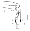
- Figure 2 illustrates the invention for use in the treatment of a movement disorder requiring stimulation of the median nerve 46.
- the median nerve 46 innervates most of the flexor muscles in front of the forearm, most of the short muscles of the thumb, and the short muscles of the hand.
- a subject's arm 48 is illustrated with the implant 18 implanted in the forearm.
- the electrical conductor 24 is illustrated with its pick-up end 26 forming a termination 30 (as a plate or sheet in the form of an oval) for receiving the electrical current from the surface cathodic electrode 20.
- the stimulating end 28 forms a termination 30 (in the form of a cuff) for delivering the electrical current to the median nerve 46.
- a surface anodic electrode 22 is positioned on the skin 10.
- a flow of electrical current from the power source 40 is supplied via cathodic wire 42 into the skin 10 at the surface cathodic electrode 20 and the surface anodic electrode 22 via anodic wire 44.
- the electrical current flows through the termination 30, the pick-up end 26, the electrical conductor 24, the stimulating end 28, a portion of the median nerve 46, the tissue between stimulating end 28 and surface anodic electrode 22 including the skin underlying electrode 22, the surface anodic electrode 22, anodic wire 44 and the power source 40, thus completing the electrical circuit.
- Some of the current flowing between the stimulating end 28 and the surface anodic electrode 22 passes through the target body tissue (in this example, median nerve 46), thereby causing the muscle 16 of the arm 48 to be stimulated.
- Figure 3 again illustrates the invention for use in the treatment of a movement disorder requiring stimulation of the median nerve 46.
- Figure 3 illustrates an electrical return conductor 34.
- the electrical circuit is essentially the same as that described for Figure 2 , with the exception that after flowing through the stimulating end 28 and the median nerve 46, the electrical current flows through termination 30, the collecting end 36, the electrical return conductor 34, the returning end 38, termination 30, the surface anodic electrode 22, anodic wire 44 and the power source 40, thus completing the electrical circuit.
- the electrical return conductor 34 acts to collect electrical current flowing through the target body tissue (i.e., median nerve 46) from the electrical conductor 24 and provides a low impedance pathway back to the surface anodic electrode 22, thereby concentrating the electric field through the target body tissue (i.e., median nerve 46).
- target body tissue i.e., median nerve 46
- Figure 4 illustrates a plurality of implants 18 for electrically stimulating more than one target body tissue independently or in unison.
- Each implant 18 is implanted entirely under the subject's skin 10 and is of a sufficient length to extend to a different target body tissue.
- the presence of multiple implants 18 necessitates positioning of a plurality of surface cathodic electrodes 20, and one or more surface anodic electrodes 22 appropriately relative to the implants 18 to stimulate the different target body tissues independently or in unison.
- Figure 4 illustrates the invention for use in the treatment of a movement disorder requiring stimulation of the median nerve 46 and the radial nerve 50.
- the radial nerve 50 innervates extensor muscles on the back of the arm and forearm, the short muscles of the thumb, and the extensor muscles of the index finger.
- Two separate surface cathodic electrodes 20 are each electrically connected via two separate cathodic wires 42 to a stimulator (not illustrated) operated by the power source 40. Electrical current is transmitted to the two separate electrical conductors 24, one of which extends to the median nerve 46, and the other to the radial nerve 50.
- An electrical return conductor 34 extends from the target tissue (i.e., below the median nerve 46) to subcutaneous tissue located below one surface anodic electrode 22.
- the electrical path of the current is as follows: cathodic wire 42, the surface cathodic electrodes 20, the skin 10, termination 30, the pick-up end 26, the electrical conductor 24, the stimulating end 28, termination 30, the median nerve 46 and/or radial nerve 50, termination 30, collecting end 36, electrical return conductor 34, returning end 38, termination 30, surface anodic electrode 22, anodic wire 44, and power source 40.
- the median nerve 46 and radial nerve 50 can be stimulated either independently by pulsatile electrical current to provide firstly, a flexion or upward position of the wrist and finger closing (via the median nerve 46), then secondly, extension or downward position of the wrist and finger extension (via the radial nerve 50).
- the median nerve 46 and radial nerve 50 can be stimulated simultaneously for example, to straighten the hand (i.e., position the wrist horizontally).
- the invention thus provides several advantages including a means of "remote” stimulation, that is the surface cathodic and anodic electrodes 20, 22 do not have to be positioned over target body tissues.
- Remote target body tissues such as nerves 12, can be stimulated from closely spaced surface cathodic and anodic electrodes 20, 22, by routing current through separate electrical conductors 24 simultaneously to several remote target body tissues.
- the electrical conductor 24 extends to a specific target body tissue, or multiple electrical conductors 24 can extend to multiple target body tissues. Stimulation is thus specific to the target body tissues, and stimulation of non-target body tissues is avoided. As an electrical conductor 24 of sufficient length is used to reach target body tissues, stimulation of target body tissues which are positioned deep within the body or organs such as the muscles, brain, cochlea, optic nerve, heart, bladder, urethra, kidneys and bones, can be achieved.
- the electrical conductor 24 is passive and can remain permanently implanted with the pick-up end 26 under the skin 10 beneath the site at which the surface cathodic electrode 20 would be placed, and the stimulating end 28 positioned proximate to the target body tissue.
- difficulty has been encountered in positioning surface electrodes accurately to obtain acceptable selectivity of stimulation of body tissues.
- the invention requires far less accuracy in positioning of the surface cathodic and anodic electrodes 20, 22; consequently, stimulation of body tissues is more accurately reproducible.
- the conductors i.e., electrical conductor 24, electrical return conductor 34
- the conductors do not emerge through the skin, thus reducing the risk of infection which may arise with percutaneous devices. There is no need to construct an implant housing its own stimulator, signal generator or power source, or to provide radio-frequency or other telemetric command signals through the skin.
- the electric currents delivered by a pulse generator to a plurality of electrodes 20, 22 may be independently controlled with the use of an interleaved pulse train.
- This comprises a sequence of stimulus pulses of different amplitudes, the pulses separated in time by a few milliseconds and delivered to each electrode in turn, the sequence as a whole being repeated at a rate such as 30 times per second.
- the amplitudes of the pulses flowing through each electrode may thereby be controlled independently.
- a plurality of surface electrodes 20, 22 may be fabricated on a single non-conductive substrate to form an electrode array that may be conveniently attached to the skin 10 in one manoeuvre.
- the plurality of terminations 30 of implanted conductors 24 may be fabricated on a substrate to form an array.
- a good spatial correspondence of surface and implanted conductors may be achieved in a convenient and reproducible manner.
- Surface electrode arrays in which the conductivity of each element of the array may be independently controlled could also be used to adjust the conductivity between the surface electrodes and the terminations in an implanted array.
Description
- The present invention relates to an implant, system and method for electrically stimulating a target body tissue in a subject.
- Electrically-excitable bodily tissues such as nerves and muscles may be activated by an electrical field applied between electrodes applied externally to the skin. Electric current flows through the skin between a cathode electrode and an anode electrode, eliciting action potentials in the nerves and muscles underlying the electrodes. This method has been used for many years in different types of stimulators, including transcutaneous electrical nerve stimulators (TENS) which relieve pain, therapeutic electrical stimulators which activate muscles for exercise purposes (Vodovnik, 1981), functional electrical stimulators which activate muscles for tasks of daily life (Kralj et al. (1989); United States Patent No.
5,330,516 to Nathan ; United States Patent No.5,562,707 to Prochazka et al. ) and stimulators that promote regeneration of damaged bones. - A disadvantage of stimulation through electrodes attached to the body surface is that many non-targeted tissues may be co-activated along with the targeted tissues. This lack of selectivity often causes unwanted sensations and/or unwanted movements. Furthermore, tissues that lie deep within the body are difficult or impossible to stimulate adequately, because most of the electrical current flowing between the electrodes flows through tissues closer to the electrodes than the targeted tissues. Selectivity may be improved by implanting wires within the body that route electrical current from a stimulator to the vicinity of the targeted tissues. This method is used in cardiac pacemakers (Horch et al., 2004), dorsal column stimulators (Waltz, 1997), deep brain stimulators (Benabid et al., (1987) and sacral root stimulators (Brindley et al. (1982). Cuffs containing the uninsulated ends of the wires may be placed around peripheral nerves to restrict most of the current to the vicinity of the nerve and limiting the spread of current to surrounding tissues, thereby improving selectivity (Haugland et al., (1999). Generally when wires are implanted, the stimulators, complete with an energy source, are also implanted (Strojnik et al., 1987). Implanted stimulators are expensive and often require a controller and/or power source external to the body. Batteries within the implanted stimulators need periodic replacement, entailing surgery.
- In a minority of cases, stimulating wires are implanted in bodily tissues and led through the skin (percutaneously) to a connector attached to the surface of the body, to which an external stimulator is attached (Peckham et al., (1980). External stimulators are much less expensive than implanted stimulators, but the percutaneous wires provide a conduit for infection and therefore require daily cleaning and maintenance. This has generally limited the use of percutaneous electrodes to short-term applications.
-
US 3,204,637 discloses a method and apparatus for stimulating nerves and muscles, wherein an implanted transducer is adapted to couple through the skin using capacitive or inductive coupling mechanisms to an external transducer. -
US 3,995,644 discloses a percutaneous device to facilitate passing electrical signals from an external stimulator to muscles and nerves. A shell is implanted below the skin, and has an electrically conductive post adapted to protrude from the skin. The post is adapted to receive a plug, which in turn is connected to the external stimulator. The plug can be readily connected and disconnected from the post. -
US 6,076,016 provides a system in which an external communication device is galvanically coupled through the skin to an implanted communication device in order to provide communication signals between the two devices. The implanted communication device can be connected to a further implanted measuring and/or controlling medical device such as a blood pressure sensor. Alternatively the implanted device might be used as a recharging circuit. - The present invention provides a system according to claim 1 for electrically stimulating a target body tissue in a subject, the system comprising:
- i) surface cathodic and anodic electrodes for making electrical contact with the subject's skin, and which, when positioned in spaced relationship on the subject's skin, for transmitting electrical current to the target body tissue;
- ii) a stimulator adapted to be provided external to the subject's body, and being electrically connected to the surface cathodic and anodic electrodes, the stimulator supplying direct, pulsatile, or alternating current to the surface cathodic and anodic electrodes; and
- iii) an implant for picking up a portion of the electrical current flowing between the surface cathodic and anodic electrodes and transmitting the portion of the electrical current to the target body tissue, the implant comprising a passive electrical conductor of sufficient length to extend, once implanted, from subcutaneous tissue located below the surface cathodic electrode to the target body tissue, the electrical conductor having a pick-up end and a stimulating end and being insulated between its ends, the pick-up end forming an electrical termination having a sufficient surface area to allow a portion of the electrical current being applied to flow through the conductor, in preference to the electrical current flowing through body tissue between the surface cathodic and anodic electrodes, such that the target body tissue is stimulated, and the stimulating end forming an electrical termination for delivering the portion of the electrical current to the target body tissue.
- In an embodiment, the system further comprises:
- an electrical return conductor of sufficient length to extend, once implanted, from the target tissue to subcutaneous tissue located below the surface anodic electrode, the return conductor having a collecting end and a returning end and being insulated between its ends, the collecting end forming an electrical termination having a sufficient surface area to allow a portion of the electrical current delivered to the target body tissue to return through the return conductor in preference to returning through body tissue, and the returning end forming an electrical termination to return the electrical current to the surface anodic electrode via the subcutaneous tissue and skin underlying the surface anodic electrode.
- In an embodiment, the system comprises a plurality of implants, the implants being configured to electrically stimulate more than one target body tissue independently or in unison, each implant being configured to be implanted entirely under the subject's skin and being of a sufficient length to extend to a different target body tissue, and the system comprising a plurality of surface cathodic electrodes and one or more surface anodic electrodes, the electrodes being configured to be positioned relative to the implants to stimulate the different target body tissues independently or in unison.
- In an embodiment, one or both of the conductor and the return conductor is formed from a metal wire, carbon fibers, a conductive rubber or other conductive polymer, or a conductive salt solution in rubber.
- In an embodiment, the terminations on one or both of the conductor and the return conductor provides an enlarged surface in the form of a coil, a spiral, a cuff, a rod, or a plate or sheet in the form of an oval or polygon.
- In an embodiment, the surface cathodic and anodic electrodes comprise a conductive plate or sheet, a conductive gel electrode, a conductive rubber or polymer electrode that may be partially coated with an electrode paste or gel, or a moistened absorbent pad electrode.
- In an embodiment, the terminations are formed from uninsulated ends of the conductor or the return conductor, or from other conductive or capacitive materials.
- In an embodiment, the system further comprises a conductive or capacitive coating, or oxide layer on one or both of the terminations.
- In an embodiment, the system further comprises a coating on one or both of the terminations for providing an anti-inflammatory, an anti-bacterial or a tissue ingrowth effect, the coating being a substance selected from the group consisting of an anti-inflammatory agent, an antibacterial agent, an antibiotic, and a tissue ingrowth promoter.
- As used herein and in the claims, the terms and phrases set out below have the following definitions.
- "Body tissue" is meant to refer to a neural tissue (in the peripheral or central nervous system), a nerve, a muscle (skeletal, respiratory, or cardiac muscle) or an organ, for example, the brain, cochlea, optic nerve, heart, bladder, urethra, kidneys and bones.
- "Electrical current" is meant to refer to resistive, capacitive, or inductive current.
- "Subject" means an animal including a human.
-
-
Figure 1 is a schematic three-dimensional view of an embodiment of the invention having an implanted electrical conductor, surface cathodic and anodic electrodes, and an implanted electrical return conductor. -
Figure 2 is a side elevation view, in section, of an embodiment of the invention having an implanted electrical conductor and surface cathodic and anodic electrodes. -
Figure 3 is a side elevation view, in section, of an alternate embodiment of the invention having an implanted electrical conductor, surface cathodic and anodic electrodes, and an electrical return conductor. -
Figure 4 is a side elevation view, in section, of an alternate embodiment of the invention having two implanted electrical conductors, two surface cathodic electrodes, an anodic electrode, and an electrical return conductor. - The subject can be an animal including a human. The body tissue can be a neural tissue (in the peripheral or central nervous system), a nerve, a muscle (skeletal, respiratory, or cardiac muscle) or an organ, for example, the brain, cochlea, optic nerve, heart, bladder, urethra, kidneys and bones. The invention can be applied to treat various conditions in which stimulation of any of these body tissues is required. Such conditions can include movement disorders (e.g., Parkinson's disease, tremor, cerebral palsy), muscular disorders (e.g., muscular dystrophy), incontinence (e.g., urinary bladder disorders), urinary retention, pain (e.g., migraine headaches, neck and back pain, pain resulting from other medical conditions), epilepsy (e.g., generalized and partial seizure disorder), cerebrovascular disorders (e.g., strokes, aneurysms), sleep disorders (e.g., sleep apnea), autonomic disorders (e.g., gastrointestinal disorders, cardiovascular disorders), disorders of vision, hearing and balance, and neuropsychiatric disorders (e.g., depression). The invention may also be used for promoting bone growth (as required, for example, in the healing of a fracture), wound healing or tissue regeneration.
- The invention is described with reference to the drawings in which like parts are labeled with the same numbers in
Figures 1 to 4 . The invention is shown generally inFigure 1 which schematically illustrates portions of a subject's body tissues, includingskin 10, anerve 12 with itsoverlying nerve sheath 14, and amuscle 16.Figure 1 also illustrates an implant indicated generally at 18, a surfacecathodic electrode 20 and a surfaceanodic electrode 22. Theimplant 18 is provided for electrically stimulating a target body tissue, such as anerve 12, in a subject. Once implanted, theimplant 18 provides a conductive pathway for at least a portion of the electrical current flowing between the surface cathodic andanodic electrodes - When positioned in spaced relationship on the subject's
skin 10, the surface cathodic andanodic electrodes skin 10 and transmit electrical current to the target body tissue. Surface cathodic andanodic electrodes anodic electrodes skin 10 may vary, depending upon the location and nature of the target body tissue. - The
implant 18 comprises anelectrical conductor 24 of sufficient length to extend, once implanted, from subcutaneous tissue located below the surfacecathodic electrode 20 to the target body tissue, forexample nerve 12. Theelectrical conductor 24 can be formed from a metal wire, carbon fibers, a conductive rubber or other conductive polymer, or a conductive salt solution in rubber. Multistranded, Teflon®-insulated, stainless-steel wire conductors of the type used in cardiac pacemaker leads have been found to be particularly effective. The electrical conductor has a pick-upend 26 and astimulating end 28, and is insulated between itsends ends ends electrical terminations 30 having sufficient surface areas for reducing the electrical impedance of the interface between the pick-up and stimulating ends 26, 28 of theelectrical conductor 24 and the surrounding body tissues. Preferably, the pick-upend 26 forms atermination 30. The pick-upend 26 forms anelectrical termination 30 which has a sufficient surface area to allow a sufficient portion of the electrical current to flow through theelectrical conductor 24, in preference to flowing through body tissue between the surface cathodic andanodic electrodes stimulating end 28 also forms anelectrical termination 30 for delivering the portion of electrical current to the target body tissue (i.e., nerve 12). -
Terminations 30 should have sufficient surface area for providing high conductivity contact with body tissues, and lowering the electrical impedance between the body tissue and the conductor. If the surface area is minimal, the amount of current flowing through a conductor to the termination is reduced to an ineffective amount. The surface area required may thus be determined by a knowledge of the electrical impedance of the interface between the tissue and theterminations 30 at the receiving and stimulating ends 26, 28. Beneficial results have been obtained by making the surface area ofmetal terminations 30 at theends terminations 30 at ends 26, 28 was then about 5 times the electrical impedance of all the subcutaneous tissue betweensurface electrodes terminations 30 plus the conductor impedance was about 2000 ohms, that is to say about ten times the tissue impedance. Thus about 10% of the current applied betweensurface electrodes conductor 24 to the target tissue. In the case of the target tissue being anerve 12 supplying amuscle 16, the amount of current betweensurface electrodes target muscle 16 then remains below the threshold level of activation of nerve endings in the subcutaneous tissue immediately betweensurface electrodes target muscles 16 can be activated with little or no local sensation under thesurface electrodes -
Terminations 30 of various shapes, materials and spatial arrangements can be used; for example,terminations 30 can provide an enlarged surface in the form of a coil, spiral, cuff, rod, or a plate or sheet in the form of an oval or polygon. As an example,Figure 1 illustrates atermination 30 as a plate or sheet in the form of an oval at the pick-upend 26 of theelectrical conductor 24, and in the form of a cuff at thestimulating end 28. The cuff or a portion thereof can encircle or partially encircle the entirety or part of thenerve sheath 14 of thenerve 12. The cuff or a portion thereof can be positioned proximate to thenerve sheath 14, or the inner surface of the cuff or a portion thereof can directly contact thenerve sheath 14. - Beneficial results are obtained with stainless-steel plates or sheets in the form of an oval which is about 0.5 square centimeter in area and 1 mm thick, or made of metal foil and stainless-steel mesh and being about 0.5 square centimeter in surface area and 0.3 mm thick. For
terminations 30 of conductors with nerve cuffs, nerve cuffs made of metal foil or stainless-steel mesh and being 0.5 to 1 square centimeter in surface area and 0.3 mm thick are suitable. Further, silastic elastomer cuffs ranging from 5mm to 15mm in length, 4 mm to 6mm inside diameter, and 1mm thick are suitable. -
Terminations 30 can be formed from uninsulated ends 26, 28 of theelectrical conductor 24, or from other conductive or capacitive materials.Terminations 30 can be formed by coiling, spiraling or weaving long, uninsulated lengths of the pick-up or stimulating ends 26, 28 to provide a sufficient surface. The surface area of the termination is thus "enlarged" relative to the surface area of a shorter length of theelectrical conductor 24. This raises the effective surface area of theterminations 30 within a small space to provide higher conductivity contact with body tissues, and to lower the electrical impedance between the body tissue and theconductor 24 to allow current flow in the conductor in preference to in the body tissue. Sufficient current flow is thereby provided in theconductor 24 to stimulate the target tissue. Alternatively, prefabricated terminations 30 (for example, plates or sheets in the form of ovals or polygons) can be attached directly to the pick-up and stimulating ends 26, 28. Further,terminations 30 can be coated or modified with conductive materials to maximize the flow of electrical current through the target body tissue. - The spatial arrangement of the
terminations 30 can be varied; for example,multiple terminations 30 can also be applied to different parts of a body tissue (Grill et al., 1996). Advantageously, theterminations 30 themselves can be in the form of closely-spaced contacts enclosed within an embracingcuff 32 placed around thenerve 12. The embracingcuff 32 can be formed from conductive silicone rubber. - Electrical impedance may be further reduced by providing conductive or capacitive coatings, or an oxide layer on the
terminations 30. The coating can be selected from a material whose structural or electrical properties improve the electrical conductance between the tissue and the conductor, for example, by providing a complex surface into which tissue can grow (for example, a polymer such as poly-diethoxy-thiophene, or suitable oxide layers including tantalum and sintered iridium). In addition, theterminations 30 can have coatings which provide an anti-inflammatory, anti-bacterial or tissue ingrowth effect. The coating can be a substance selected from an anti-inflammatory agent, antibacterial agent, antibiotic, or a tissue ingrowth promoter. - Optionally, performance of the invention can be improved by implanting an
electrical return conductor 34 of sufficient length to extend from the target body tissue to subcutaneous tissue located below the surfaceanodic electrode 22. Theelectrical return conductor 34 provides a low-impedance conductive pathway from the target body tissue to the surfaceanodic electrode 22, thereby concentrating the electric field through the target tissue. Theelectrical return conductor 34 can be formed from a metal wire, carbon fibers, a conductive rubber or other conductive polymer, or a conductive salt solution in rubber. Theelectrical return conductor 34 has a collectingend 36 and a returningend 38, and is insulated between itsends end 36 and the returningend 38 form electrical terminations 30 (as described above) for reducing the electrical impedance of the interface between the collectingend 36 and returningend 38 of theelectrical return conductor 34 and the surrounding body tissues. The collectingend 36 forms an electrical termination 30 (shown inFigure 1 in the form of a cuff), which has a sufficient surface area to allow a portion of the electrical current delivered to the target body tissue to return through theelectrical return conductor 34 in preference to returning through body tissue. The returningend 38 forms an electrical termination 30 (shown inFigure 1 as a plate or sheet in the form of an oval) which returns the electrical current to the surfaceanodic electrode 22 via the subcutaneous tissue and skin underlying the surfaceanodic electrode 22. - A power source 40 (shown in
Figures 2-4 ) provides operating power to a stimulator (not illustrated) which is external to the subject's body. The stimulator is electrically connected to the surface cathodic andanodic electrodes anodic electrodes electrodes anodic electrodes implant 18 sufficient to stimulate the target body tissue. - Exemplary pulse parameters of electrical current flowing between the surface cathodic and
anodic electrodes surface electrodes conductor 24, even when there is noelectrical return conductor 34. The type of current may be dependent upon the application for which the invention is intended; for example, continuous current would be applied, rather than pulsatile current, when the target body tissue is bone and promotion of bone growth is desired. - Although most of the electrical current flows through the body tissues in proximity to the surface cathodic and
anodic electrodes electrical conductor 24,nerve 12, andelectrical return conductor 34. As shown inFigure 1 , thesurface cathodic electrode 20 is positioned over the pick-upend 26 of theelectrical conductor 24, so that a portion of the current is transmitted through theconductor 24 to the target body tissue, and current flows through the target body tissue and returns to theanodic surface electrode 22 through body tissues. This can also be achieved through the implantedelectrical return conductor 34 extending between the target body tissue and subcutaneous tissue located below the surfaceanodic electrode 22. - The complete electrical path of the portion of the electrical current is as follows:
cathodic wire 42,surface cathodic electrode 20,skin 10, termination 30 (as a plate or sheet), pick-upend 26,electrical conductor 24, stimulatingend 28, termination 30 (in the form of a cuff),nerve sheath 14,nerve 12,termination 30, collectingend 36,electrical return conductor 34, returningend 38,termination 30,skin 10, surfaceanodic electrode 22 andanodic wire 44. The pulses of electrical current elicit action potentials are conducted alongnerve 12 tomuscle 16, causing it to contract. - As an example,
Figure 2 illustrates the invention for use in the treatment of a movement disorder requiring stimulation of themedian nerve 46. Themedian nerve 46 innervates most of the flexor muscles in front of the forearm, most of the short muscles of the thumb, and the short muscles of the hand. A subject'sarm 48 is illustrated with theimplant 18 implanted in the forearm. Theelectrical conductor 24 is illustrated with its pick-upend 26 forming a termination 30 (as a plate or sheet in the form of an oval) for receiving the electrical current from thesurface cathodic electrode 20. Thestimulating end 28 forms a termination 30 (in the form of a cuff) for delivering the electrical current to themedian nerve 46. Asurface anodic electrode 22 is positioned on theskin 10. A flow of electrical current from thepower source 40 is supplied viacathodic wire 42 into theskin 10 at thesurface cathodic electrode 20 and the surfaceanodic electrode 22 viaanodic wire 44. The electrical current flows through thetermination 30, the pick-upend 26, theelectrical conductor 24, thestimulating end 28, a portion of themedian nerve 46, the tissue between stimulatingend 28 and surfaceanodic electrode 22 including theskin underlying electrode 22, the surfaceanodic electrode 22,anodic wire 44 and thepower source 40, thus completing the electrical circuit. Some of the current flowing between thestimulating end 28 and the surfaceanodic electrode 22 passes through the target body tissue (in this example, median nerve 46), thereby causing themuscle 16 of thearm 48 to be stimulated. - As a further example,
Figure 3 again illustrates the invention for use in the treatment of a movement disorder requiring stimulation of themedian nerve 46. However, in addition to the components shown inFigure 2 ,Figure 3 illustrates anelectrical return conductor 34. The electrical circuit is essentially the same as that described forFigure 2 , with the exception that after flowing through thestimulating end 28 and themedian nerve 46, the electrical current flows throughtermination 30, the collectingend 36, theelectrical return conductor 34, the returningend 38,termination 30, the surfaceanodic electrode 22,anodic wire 44 and thepower source 40, thus completing the electrical circuit. Advantageously, theelectrical return conductor 34 acts to collect electrical current flowing through the target body tissue (i.e., median nerve 46) from theelectrical conductor 24 and provides a low impedance pathway back to the surfaceanodic electrode 22, thereby concentrating the electric field through the target body tissue (i.e., median nerve 46). - As yet a further example,
Figure 4 illustrates a plurality ofimplants 18 for electrically stimulating more than one target body tissue independently or in unison. Eachimplant 18 is implanted entirely under the subject'sskin 10 and is of a sufficient length to extend to a different target body tissue. The presence ofmultiple implants 18 necessitates positioning of a plurality of surfacecathodic electrodes 20, and one or more surfaceanodic electrodes 22 appropriately relative to theimplants 18 to stimulate the different target body tissues independently or in unison.Figure 4 illustrates the invention for use in the treatment of a movement disorder requiring stimulation of themedian nerve 46 and theradial nerve 50. Theradial nerve 50 innervates extensor muscles on the back of the arm and forearm, the short muscles of the thumb, and the extensor muscles of the index finger. Two separate surfacecathodic electrodes 20 are each electrically connected via two separatecathodic wires 42 to a stimulator (not illustrated) operated by thepower source 40. Electrical current is transmitted to the two separateelectrical conductors 24, one of which extends to themedian nerve 46, and the other to theradial nerve 50. Anelectrical return conductor 34 extends from the target tissue (i.e., below the median nerve 46) to subcutaneous tissue located below onesurface anodic electrode 22. - The electrical path of the current is as follows:
cathodic wire 42, the surfacecathodic electrodes 20, theskin 10,termination 30, the pick-upend 26, theelectrical conductor 24, thestimulating end 28,termination 30, themedian nerve 46 and/orradial nerve 50,termination 30, collectingend 36,electrical return conductor 34, returningend 38,termination 30, surfaceanodic electrode 22,anodic wire 44, andpower source 40. Themedian nerve 46 andradial nerve 50 can be stimulated either independently by pulsatile electrical current to provide firstly, a flexion or upward position of the wrist and finger closing (via the median nerve 46), then secondly, extension or downward position of the wrist and finger extension (via the radial nerve 50). Alternatively, themedian nerve 46 andradial nerve 50 can be stimulated simultaneously for example, to straighten the hand (i.e., position the wrist horizontally). - The invention thus provides several advantages including a means of "remote" stimulation, that is the surface cathodic and
anodic electrodes nerves 12, can be stimulated from closely spaced surface cathodic andanodic electrodes electrical conductors 24 simultaneously to several remote target body tissues. - Further, greater selectivity is provided in stimulating target body tissues. The
electrical conductor 24 extends to a specific target body tissue, or multipleelectrical conductors 24 can extend to multiple target body tissues. Stimulation is thus specific to the target body tissues, and stimulation of non-target body tissues is avoided. As anelectrical conductor 24 of sufficient length is used to reach target body tissues, stimulation of target body tissues which are positioned deep within the body or organs such as the muscles, brain, cochlea, optic nerve, heart, bladder, urethra, kidneys and bones, can be achieved. - Stimulation is reproducible at will. The
electrical conductor 24 is passive and can remain permanently implanted with the pick-upend 26 under theskin 10 beneath the site at which thesurface cathodic electrode 20 would be placed, and thestimulating end 28 positioned proximate to the target body tissue. To the inventor's knowledge, difficulty has been encountered in positioning surface electrodes accurately to obtain acceptable selectivity of stimulation of body tissues. The inventor has discovered that surprisingly, the invention requires far less accuracy in positioning of the surface cathodic andanodic electrodes - Further, the invention avoids problems inherent in other forms of stimulation. The conductors (i.e.,
electrical conductor 24, electrical return conductor 34) do not emerge through the skin, thus reducing the risk of infection which may arise with percutaneous devices. There is no need to construct an implant housing its own stimulator, signal generator or power source, or to provide radio-frequency or other telemetric command signals through the skin. - As is known to those skilled in the art, the electric currents delivered by a pulse generator to a plurality of
electrodes - A plurality of
surface electrodes skin 10 in one manoeuvre. Similarly, the plurality ofterminations 30 of implantedconductors 24 may be fabricated on a substrate to form an array. By matching the physical layout of the surface electrode array to that of the implanted terminations array, a good spatial correspondence of surface and implanted conductors may be achieved in a convenient and reproducible manner. Surface electrode arrays in which the conductivity of each element of the array may be independently controlled could also be used to adjust the conductivity between the surface electrodes and the terminations in an implanted array. - It will be apparent to one skilled in the art that modifications may be made to the illustrated embodiment without departing from the scope of the invention as hereinafter defined in the claims.
-
- Benabid, A. L., Pollak, P., Louveau, A., Henry, S. and De Rougemont, J. (1987) Combined (thalamotomy and stimulation) stereotactic surgery of the VIM thalamic nucleus for bilateral Parkinson disease. Applied Neurophysiology 50:344-346.
- Brindley, G. S., Polkey, C. E. & Rushton, D. N. (1982) Sacral anterior root stimulators for bladder control in paraplegia. Paraplegia 20:365-381.
- Grill, W.M., Jr. and Mortimer, J.T. (1996) Quantification of recruitment properties of multiple contact cuff electrodes. IEEE Trans. Rehabil. Eng. (4(2):49-62.
- Haugland, M. & Sinkjaer, T. (1999) Interfacing the body's own sensing receptors into neural prosthesis devices. Technology & Health Care 7:393-399.
- Horch, K.W. and Dhillon, G. S., ed. (2004) Neuroprosthetics. Theory and Practice. Vol. 2. World Scientific, New Jersey.
- Kralj, A. R. & Bajd, T. (1989) Functional Electrical Stimulation: Standing and Walking after Spinal Cord Injury. CRC Press, Boca Raton, FL.
- Peckham, P. H., Marsolais, E. B. and Mortimer, J. T. (1980) Restoration of key grip and release in the C6 tetraplegic patient through functional electrical stimulation. J. Hand Surg. 5:462-469.
- Prochazka, A., Gauthier, M., Wieler, M. and Kenwell, Z. (1997) The bionic glove: an electrical stimulator garment that provides controlled grasp and hand opening in quadriplegia. Arch. Phys. Med. Rehabil. 78:608-614.
- Strojnik, P., Acimovic, R., Vavken, E., Simic, V. and Stanic, U. (1987) Treatment of drop foot using an implantable peroneal underknee stimulator. Scandinavian J. of Rehabil. Med. 19:37-43.
- Vodovnik, L. (1981) Therapeutic effects of functional electrical stimulation of extremities. Medical and Biological Engineering & Computing 19:470-478.
- Waltz, J. M. (1997) Spinal cord stimulation: a quarter century of development and investigation. A review of its development and effectiveness in 1,336 cases. Stereotactic & Functional Neurosurgery 69:288-299.
-
- Nathan, R. H. (1994) Device for generating hand function. United States Patent No.
5,330,516, issued July 19, 1994 . - Prochazka, A., Wieler, M., Kenwell, Z.R., Gauthier, M.J.A. (1996) Garment for applying controlled electrical stimulation to restore motor function. United States Patent No.
5,562,707, issued October 8, 1996 . - Prochazka, A. (2003) Method and apparatus for controlling a device or process with vibrations generated by tooth clicks. International Patent Application Publication No.
WO 2004/034937, published October 16, 2003 . - All publications mentioned in this specification are indicative of the level of skill in the art to which this invention pertains. Although the foregoing invention has been described in some detail by way of illustration and example, for purposes of clarity and understanding it will be understood that certain changes and modifications may be made without departing from the scope of the invention as defined by the following claims.
Claims (9)
- A system for electrically stimulating a target body tissue in a subject, the system comprising:i) surface cathodic and anodic electrodes (20, 22) for making electrical contact with the subject's skin and which, when positioned in spaced relationship on the subject's skin, for transmitting electrical current to the target body tissue;ii) a stimulator (40) adapted to be provided external to the subject's body and being electrically connected to the surface cathodic and anodic electrodes (20, 22), the stimulator (40) supplying direct, pulsatile, or alternating current to the surface cathodic and anodic electrodes (20, 22); andiii) an implant (18) for picking up a portion of the electrical current flowing between the surface cathodic and anodic electrodes (20, 22) and transmitting the portion of the electrical current to the target body tissue, the implant comprising a passive electrical conductor (24) of sufficient length to extend, once implanted, from subcutaneous tissue located below the surface cathodic electrode (20) to the target body tissue, the electrical conductor (24) having a pick-up end (26) and a stimulating end (28) and being insulated between its ends (26, 28), the pick-up end (26) forming an electrical termination (30) having a sufficient surface area to allow a portion of the electrical current being applied to flow through the conductor (24), in preference to the electrical current flowing through body tissue between the surface cathodic and anodic electrodes (20, 22), such that the target body tissue is stimulated, and the stimulating end (28) forming an electrical termination (30) for delivering the portion of the electrical current to the target body tissue.
- The system according to claim 1, further comprising:an electrical return conductor (34) of sufficient length to extend, once implanted, from the target tissue to subcutaneous tissue located below the surface anodic electrode (22), the return conductor having a collecting end (36) and a returning end (38) and being insulated between its ends (36, 38), the collecting end (36) forming an electrical termination (30) having a sufficient surface area to allow a portion of the electrical current delivered to the target body tissue to return through the return conductor (34) in preference to returning through body tissue, and the returning end (38) forming an electrical termination (30) to return the electrical current to the surface anodic electrode (22) via the subcutaneous tissue and skin underlying the surface anodic electrode (22).
- The system according to claim 1 or 2, wherein the system comprises a plurality of implants (18), the implants (18) being configured to electrically stimulate more than one target body tissue independently or in unison, each implant (18) being configured to be implanted entirely under the subject's skin and being of a sufficient length to extend to a different target body tissue, and the system comprising a plurality of surface cathodic electrodes (20) and one or more surface anodic electrodes (22), the electrodes (20, 22) being configured to be positioned relative to the implants (18) to stimulate the different target body tissues independently or in unison.
- The system according to claim 1, 2 or 3, wherein one or both of the conductor (24) and the return conductor (34) is formed from a metal wire, carbon fibers, a conductive rubber or other conductive polymer, or a conductive salt solution in rubber.
- The system according to claim 4, wherein the terminations (30) on one or both of the conductor (24) and the return conductor (34) provides an enlarged surface in the form of a coil, a spiral, a cuff, a rod, or a plate or sheet in the form of an oval or polygon.
- The system according to any of claims 1 to 5, wherein the surface cathodic and anodic electrodes (20, 22) comprise a conductive plate or sheet, a conductive gel electrode, a conductive rubber or polymer electrode that may be partially coated with an electrode paste or gel, or a moistened absorbent pad electrode.
- The system according to claim 5, wherein the terminations (30) are formed from uninsulated ends (26, 28, 36, 38) of the conductor (24) or the return conductor (34), or from other conductive or capacitive materials.
- The system according to claim 5, further comprising a conductive or capacitive coating, or oxide layer on one or both of the terminations (30).
- The system according to claim 5, further comprising a coating on one or both of the terminations (30) for providing an anti-inflammatory, an anti-bacterial or a tissue ingrowth effect, the coating being a substance selected from the group consisting of an anti-inflammatory agent, an antibacterial agent, an antibiotic, and a tissue ingrowth promoter.
Applications Claiming Priority (2)
| Application Number | Priority Date | Filing Date | Title |
|---|---|---|---|
| US53861804P | 2004-01-22 | 2004-01-22 | |
| PCT/CA2005/000074 WO2005070494A1 (en) | 2004-01-22 | 2005-01-24 | Method of routing electrical current to bodily tissues via implanted passive conductors |
Publications (3)
| Publication Number | Publication Date |
|---|---|
| EP1706178A1 EP1706178A1 (en) | 2006-10-04 |
| EP1706178A4 EP1706178A4 (en) | 2009-02-25 |
| EP1706178B1 true EP1706178B1 (en) | 2013-04-24 |
Family
ID=34807198
Family Applications (1)
| Application Number | Title | Priority Date | Filing Date |
|---|---|---|---|
| EP05700290.9A Active EP1706178B1 (en) | 2004-01-22 | 2005-01-24 | System for routing electrical current to bodily tissues via implanted passive conductors |
Country Status (6)
| Country | Link |
|---|---|
| US (4) | US7502652B2 (en) |
| EP (1) | EP1706178B1 (en) |
| JP (1) | JP4879754B2 (en) |
| AU (1) | AU2005205853B2 (en) |
| CA (1) | CA2553901C (en) |
| WO (1) | WO2005070494A1 (en) |
Cited By (8)
| Publication number | Priority date | Publication date | Assignee | Title |
|---|---|---|---|---|
| US9643022B2 (en) | 2013-06-17 | 2017-05-09 | Nyxoah SA | Flexible control housing for disposable patch |
| US9849289B2 (en) | 2009-10-20 | 2017-12-26 | Nyxoah SA | Device and method for snoring detection and control |
| US9855032B2 (en) | 2012-07-26 | 2018-01-02 | Nyxoah SA | Transcutaneous power conveyance device |
| US10052097B2 (en) | 2012-07-26 | 2018-08-21 | Nyxoah SA | Implant unit delivery tool |
| US10751537B2 (en) | 2009-10-20 | 2020-08-25 | Nyxoah SA | Arced implant unit for modulation of nerves |
| US10814137B2 (en) | 2012-07-26 | 2020-10-27 | Nyxoah SA | Transcutaneous power conveyance device |
| US11253712B2 (en) | 2012-07-26 | 2022-02-22 | Nyxoah SA | Sleep disordered breathing treatment apparatus |
| US11273307B2 (en) | 2009-10-20 | 2022-03-15 | Nyxoah SA | Method and device for treating sleep apnea |
Families Citing this family (277)
| Publication number | Priority date | Publication date | Assignee | Title |
|---|---|---|---|---|
| US7258690B2 (en) | 2003-03-28 | 2007-08-21 | Relievant Medsystems, Inc. | Windowed thermal ablation probe |
| US8613744B2 (en) | 2002-09-30 | 2013-12-24 | Relievant Medsystems, Inc. | Systems and methods for navigating an instrument through bone |
| US8808284B2 (en) | 2008-09-26 | 2014-08-19 | Relievant Medsystems, Inc. | Systems for navigating an instrument through bone |
| US8361067B2 (en) | 2002-09-30 | 2013-01-29 | Relievant Medsystems, Inc. | Methods of therapeutically heating a vertebral body to treat back pain |
| US6907884B2 (en) | 2002-09-30 | 2005-06-21 | Depay Acromed, Inc. | Method of straddling an intraosseous nerve |
| JP4879754B2 (en) | 2004-01-22 | 2012-02-22 | リハブトロニクス インコーポレーテッド | Method for carrying electrical current to body tissue via implanted non-active conductor |
| US20100016929A1 (en) * | 2004-01-22 | 2010-01-21 | Arthur Prochazka | Method and system for controlled nerve ablation |
| US8751003B2 (en) | 2004-02-11 | 2014-06-10 | Ethicon, Inc. | Conductive mesh for neurostimulation |
| US7979137B2 (en) | 2004-02-11 | 2011-07-12 | Ethicon, Inc. | System and method for nerve stimulation |
| US8788044B2 (en) | 2005-01-21 | 2014-07-22 | Michael Sasha John | Systems and methods for tissue stimulation in medical treatment |
| US8391990B2 (en) | 2005-05-18 | 2013-03-05 | Cardiac Pacemakers, Inc. | Modular antitachyarrhythmia therapy system |
| US8588930B2 (en) * | 2005-06-07 | 2013-11-19 | Ethicon, Inc. | Piezoelectric stimulation device |
| CA2608397A1 (en) | 2005-06-28 | 2007-01-04 | Bioness Development, Llc | Improvements to an implant, system and method using implanted passive conductors for routing electrical current |
| US20070073354A1 (en) * | 2005-09-26 | 2007-03-29 | Knudson Mark B | Neural blocking therapy |
| US9126050B2 (en) * | 2009-03-20 | 2015-09-08 | ElectroCore, LLC | Non-invasive vagus nerve stimulation devices and methods to treat or avert atrial fibrillation |
| US9339641B2 (en) | 2006-01-17 | 2016-05-17 | Emkinetics, Inc. | Method and apparatus for transdermal stimulation over the palmar and plantar surfaces |
| US9610459B2 (en) | 2009-07-24 | 2017-04-04 | Emkinetics, Inc. | Cooling systems and methods for conductive coils |
| EP1981589B1 (en) * | 2006-01-23 | 2016-04-13 | Rehabtronics Inc. | System for routing electrical current to bodily tissues via implanted passive conductors |
| US8027718B2 (en) * | 2006-03-07 | 2011-09-27 | Mayo Foundation For Medical Education And Research | Regional anesthetic |
| US8180462B2 (en) | 2006-04-18 | 2012-05-15 | Cyberonics, Inc. | Heat dissipation for a lead assembly |
| US8478420B2 (en) | 2006-07-12 | 2013-07-02 | Cyberonics, Inc. | Implantable medical device charge balance assessment |
| US20080027524A1 (en) | 2006-07-26 | 2008-01-31 | Maschino Steven E | Multi-electrode assembly for an implantable medical device |
| US10786669B2 (en) | 2006-10-02 | 2020-09-29 | Emkinetics, Inc. | Method and apparatus for transdermal stimulation over the palmar and plantar surfaces |
| EP2069013A2 (en) * | 2006-10-02 | 2009-06-17 | Emkinetics, Inc. | Method and apparatus for magnetic induction therapy |
| US11224742B2 (en) | 2006-10-02 | 2022-01-18 | Emkinetics, Inc. | Methods and devices for performing electrical stimulation to treat various conditions |
| US8483820B2 (en) * | 2006-10-05 | 2013-07-09 | Bioness Inc. | System and method for percutaneous delivery of electrical stimulation to a target body tissue |
| US7783363B2 (en) * | 2006-10-23 | 2010-08-24 | Artis Nanomedica, Inc. | Neural bridge gateway and calibrator |
| US7783360B2 (en) * | 2006-10-23 | 2010-08-24 | Bojan Zdravkovic | Sensory system |
| US7974707B2 (en) | 2007-01-26 | 2011-07-05 | Cyberonics, Inc. | Electrode assembly with fibers for a medical device |
| US20090012590A1 (en) * | 2007-07-03 | 2009-01-08 | Cyberonics, Inc. | Neural Conductor |
| US9757554B2 (en) | 2007-08-23 | 2017-09-12 | Bioness Inc. | System for transmitting electrical current to a bodily tissue |
| US8467880B2 (en) | 2007-08-23 | 2013-06-18 | Bioness Inc. | System for transmitting electrical current to a bodily tissue |
| US8738137B2 (en) | 2007-08-23 | 2014-05-27 | Bioness Inc. | System for transmitting electrical current to a bodily tissue |
| US8868203B2 (en) | 2007-10-26 | 2014-10-21 | Cyberonics, Inc. | Dynamic lead condition detection for an implantable medical device |
| US8942798B2 (en) | 2007-10-26 | 2015-01-27 | Cyberonics, Inc. | Alternative operation mode for an implantable medical device based upon lead condition |
| PL2209518T3 (en) * | 2007-10-29 | 2018-08-31 | Case Western Reserve University | Onset-mitigating high-frequency nerve block |
| US20090204173A1 (en) * | 2007-11-05 | 2009-08-13 | Zi-Ping Fang | Multi-Frequency Neural Treatments and Associated Systems and Methods |
| WO2009100531A1 (en) | 2008-02-15 | 2009-08-20 | Angeltear Solutions Inc. | Adjustable tissue or nerve cuff and method of use |
| JP4475343B2 (en) * | 2008-04-04 | 2010-06-09 | 村田機械株式会社 | E-mail gateway device |
| US8473062B2 (en) | 2008-05-01 | 2013-06-25 | Autonomic Technologies, Inc. | Method and device for the treatment of headache |
| US20090326602A1 (en) * | 2008-06-27 | 2009-12-31 | Arkady Glukhovsky | Treatment of indications using electrical stimulation |
| EP3406210A1 (en) | 2008-09-26 | 2018-11-28 | Relievant Medsystems, Inc. | Systems and for navigating an instrument through bone |
| US10028753B2 (en) | 2008-09-26 | 2018-07-24 | Relievant Medsystems, Inc. | Spine treatment kits |
| US8630711B1 (en) * | 2008-10-02 | 2014-01-14 | University Of Utah Research Foundation | Systems and methods for treating disorders by selectively activating and/or blocking muscles through intrafasicular stimulation of the pudendal nerve |
| US8335570B2 (en) | 2008-10-09 | 2012-12-18 | Boston Scientific Neuromodulation Corporation | Electrical stimulation leads having RF compatibility and methods of use and manufacture |
| US8255057B2 (en) | 2009-01-29 | 2012-08-28 | Nevro Corporation | Systems and methods for producing asynchronous neural responses to treat pain and/or other patient conditions |
| US9327121B2 (en) | 2011-09-08 | 2016-05-03 | Nevro Corporation | Selective high frequency spinal cord modulation for inhibiting pain, including cephalic and/or total body pain with reduced side effects, and associated systems and methods |
| GB2465581B (en) * | 2008-11-20 | 2013-03-20 | Synapse Microcurrent Ltd | Method and device for verifying the electrical output of a microcurrent therapy device |
| US8412336B2 (en) | 2008-12-29 | 2013-04-02 | Autonomic Technologies, Inc. | Integrated delivery and visualization tool for a neuromodulation system |
| US9320908B2 (en) | 2009-01-15 | 2016-04-26 | Autonomic Technologies, Inc. | Approval per use implanted neurostimulator |
| US8494641B2 (en) | 2009-04-22 | 2013-07-23 | Autonomic Technologies, Inc. | Implantable neurostimulator with integral hermetic electronic enclosure, circuit substrate, monolithic feed-through, lead assembly and anchoring mechanism |
| EP2243510B1 (en) | 2009-04-22 | 2014-04-09 | Nevro Corporation | Sytems for selective high frequency spinal cord modulation for inhibiting pain with reduced side effects |
| ES2942684T3 (en) | 2009-04-22 | 2023-06-05 | Nevro Corp | Spinal cord modulation systems to induce paresthetic and anesthetic effects |
| US8498710B2 (en) | 2009-07-28 | 2013-07-30 | Nevro Corporation | Linked area parameter adjustment for spinal cord stimulation and associated systems and methods |
| US8380324B2 (en) | 2009-08-20 | 2013-02-19 | Boston Scientific Neuromodulation Corporation | Systems and methods for altering one or more RF-response properties of electrical stimulation systems |
| ES2552308T3 (en) * | 2009-09-03 | 2015-11-27 | Murdoch Childrens Research Institute | Transcutaneous stimulation system |
| WO2011041203A2 (en) | 2009-09-30 | 2011-04-07 | Mayo Foundation For Medical Education And Research | Percutaneous placement of electrodes |
| KR20120101648A (en) | 2009-10-05 | 2012-09-14 | 뉴로시그마, 아이엔씨. | Extracranial implantable devices, systems and methods for the treatment of neurological disorders |
| AU2010313487A1 (en) | 2009-10-26 | 2012-05-24 | Emkinetics, Inc. | Method and apparatus for electromagnetic stimulation of nerve, muscle, and body tissues |
| US8843188B2 (en) | 2009-11-23 | 2014-09-23 | Case Western Reserve University | Adjustable nerve electrode |
| US8478428B2 (en) | 2010-04-23 | 2013-07-02 | Cyberonics, Inc. | Helical electrode for nerve stimulation |
| EP2394693A1 (en) * | 2010-06-10 | 2011-12-14 | Golsen Limited | Electrical impulse stimulation device for the healing of wounds |
| US8805519B2 (en) | 2010-09-30 | 2014-08-12 | Nevro Corporation | Systems and methods for detecting intrathecal penetration |
| US8965482B2 (en) | 2010-09-30 | 2015-02-24 | Nevro Corporation | Systems and methods for positioning implanted devices in a patient |
| US9457186B2 (en) | 2010-11-15 | 2016-10-04 | Bluewind Medical Ltd. | Bilateral feedback |
| CN103313754B (en) | 2010-11-16 | 2015-09-30 | 小利兰·斯坦福大学理事会 | Be used for the treatment of the system and method for xerophthalmia |
| US9821159B2 (en) | 2010-11-16 | 2017-11-21 | The Board Of Trustees Of The Leland Stanford Junior University | Stimulation devices and methods |
| WO2012075192A2 (en) | 2010-11-30 | 2012-06-07 | The Regents Of The University Of California | Pulse generator for cranial nerve stimulation |
| WO2012075198A2 (en) | 2010-11-30 | 2012-06-07 | Nevro Corporation | Extended pain relief via high frequency spinal cord modulation, and associated systems and methods |
| CA2821721A1 (en) | 2010-12-14 | 2012-06-21 | The Regents Of The University Of California | Extracranial implantable devices, systems and methods for the treatment of medical disorders |
| US20140135886A1 (en) | 2010-12-14 | 2014-05-15 | United States Government Department Of Veterans Affairs | Devices, systems and methods for the treatment of medical disorders |
| AU2012204526B2 (en) | 2011-01-03 | 2016-05-19 | California Institute Of Technology | High density epidural stimulation for facilitation of locomotion, posture, voluntary movement, and recovery of autonomic, sexual, vasomotor, and cognitive function after neurological injury |
| EP2665514B1 (en) | 2011-01-21 | 2017-07-26 | California Institute of Technology | A parylene-based microelectrode array implant for spinal cord stimulation |
| CN103492024B (en) | 2011-03-02 | 2016-02-10 | 默多克儿童研究所 | Percutaneous stimulation method and system |
| BR112013024491A2 (en) | 2011-03-24 | 2017-03-21 | California Inst Of Techn | neurostimulator. |
| US8868217B2 (en) | 2011-06-27 | 2014-10-21 | Bioness Neuromodulation Ltd. | Electrode for muscle stimulation |
| AU2012318586B2 (en) | 2011-10-04 | 2017-06-08 | Nevro Corporation | Modeling positions of implanted devices in a patient |
| US8712534B2 (en) * | 2011-10-28 | 2014-04-29 | Medtronic, Inc. | Combined high and low frequency stimulation therapy |
| CA2864473C (en) | 2011-11-11 | 2021-10-19 | The Regents Of The University Of California | Transcutaneous spinal cord stimulation: noninvasive tool for activation of locomotor circuitry |
| US10092750B2 (en) | 2011-11-11 | 2018-10-09 | Neuroenabling Technologies, Inc. | Transcutaneous neuromodulation system and methods of using same |
| MX341649B (en) | 2011-11-11 | 2016-08-29 | Neuroenabling Tech Inc | Non invasive neuromodulation device for enabling recovery of motor, sensory, autonomic, sexual, vasomotor and cognitive function. |
| US10390877B2 (en) | 2011-12-30 | 2019-08-27 | Relievant Medsystems, Inc. | Systems and methods for treating back pain |
| WO2013111137A2 (en) | 2012-01-26 | 2013-08-01 | Rainbow Medical Ltd. | Wireless neurqstimulatqrs |
| US8676331B2 (en) | 2012-04-02 | 2014-03-18 | Nevro Corporation | Devices for controlling spinal cord modulation for inhibiting pain, and associated systems and methods, including controllers for automated parameter selection |
| US9694181B2 (en) * | 2012-06-15 | 2017-07-04 | Case Western Reserve University | Methods of treatment of a neurological disorder using electrical nerve conduction block |
| US10195434B2 (en) * | 2012-06-15 | 2019-02-05 | Case Western Reserve University | Treatment of pain using electrical nerve conduction block |
| WO2013188753A1 (en) | 2012-06-15 | 2013-12-19 | Case Western Reserve University | Therapy delivery devices and methods for non-damaging neural tissue conduction block |
| US9833614B1 (en) | 2012-06-22 | 2017-12-05 | Nevro Corp. | Autonomic nervous system control via high frequency spinal cord modulation, and associated systems and methods |
| US10588691B2 (en) | 2012-09-12 | 2020-03-17 | Relievant Medsystems, Inc. | Radiofrequency ablation of tissue within a vertebral body |
| WO2014071161A1 (en) | 2012-11-05 | 2014-05-08 | Relievant Medsystems, Inc. | System and methods for creating curved paths through bone and modulating nerves within the bone |
| WO2014087337A1 (en) | 2012-12-06 | 2014-06-12 | Bluewind Medical Ltd. | Delivery of implantable neurostimulators |
| US10838406B2 (en) | 2013-02-11 | 2020-11-17 | The Aerospace Corporation | Systems and methods for the patterning of material substrates |
| US8679189B1 (en) * | 2013-02-11 | 2014-03-25 | Amendia Inc. | Bone growth enhancing implant |
| WO2014138709A1 (en) | 2013-03-08 | 2014-09-12 | Oculeve, Inc. | Devices and methods for treating dry eye in animals |
| US9717627B2 (en) | 2013-03-12 | 2017-08-01 | Oculeve, Inc. | Implant delivery devices, systems, and methods |
| US9993642B2 (en) | 2013-03-15 | 2018-06-12 | The Regents Of The University Of California | Multi-site transcutaneous electrical stimulation of the spinal cord for facilitation of locomotion |
| WO2014165745A1 (en) | 2013-04-04 | 2014-10-09 | Drexel University | Treatment for cardiac conductance abnormalities |
| US10155108B2 (en) | 2013-04-19 | 2018-12-18 | Oculeve, Inc. | Nasal stimulation devices and methods |
| US20150238764A1 (en) | 2013-05-10 | 2015-08-27 | Case Western Reserve University | Systems and methods for preventing noise in an electric waveform for neural stimulation, block, or sensing |
| EP3441109A1 (en) | 2013-05-30 | 2019-02-13 | Graham H. Creasey | Flexible dermal patch for a topical nerve stimulator system |
| US11229789B2 (en) | 2013-05-30 | 2022-01-25 | Neurostim Oab, Inc. | Neuro activator with controller |
| US9895539B1 (en) | 2013-06-10 | 2018-02-20 | Nevro Corp. | Methods and systems for disease treatment using electrical stimulation |
| US9724151B2 (en) | 2013-08-08 | 2017-08-08 | Relievant Medsystems, Inc. | Modulating nerves within bone using bone fasteners |
| EP3782698A1 (en) | 2013-09-27 | 2021-02-24 | The Regents Of The University Of California | Engaging the cervical spinal cord circuitry to re- enable volitional control of hand function in tetraplegic subjects |
| AU2014334499A1 (en) | 2013-10-11 | 2016-03-17 | Gi Therapies Pty Ltd | System, device and garment for delivering transcutaneous electrical stimulation |
| US10149978B1 (en) | 2013-11-07 | 2018-12-11 | Nevro Corp. | Spinal cord modulation for inhibiting pain via short pulse width waveforms, and associated systems and methods |
| US20160263376A1 (en) | 2013-11-27 | 2016-09-15 | The Governing Council Of The University Of Toronto | Systems and methods for improved treatment of overactive bladder |
| US10556107B2 (en) | 2013-11-27 | 2020-02-11 | Ebt Medical, Inc. | Systems, methods and kits for peripheral nerve stimulation |
| EP3950048A1 (en) * | 2013-11-27 | 2022-02-09 | EBT Medical, Inc. | System for treating patient's incontinence dysfunction |
| US11633593B2 (en) | 2013-11-27 | 2023-04-25 | Ebt Medical, Inc. | Treatment of pelvic floor disorders using targeted lower limb nerve stimulation |
| JP6781044B2 (en) | 2014-01-10 | 2020-11-04 | カーディアック ペースメイカーズ, インコーポレイテッド | System to detect cardiac arrhythmia |
| US20150196769A1 (en) | 2014-01-10 | 2015-07-16 | Cardiac Pacemakers, Inc. | Methods and systems for improved communication between medical devices |
| WO2015106286A1 (en) | 2014-01-13 | 2015-07-16 | California Institute Of Technology | Neuromodulation systems and methods of using same |
| JP6604963B2 (en) | 2014-02-25 | 2019-11-20 | オキュリーブ, インコーポレイテッド | Polymer formulations for nasolacrimal gland stimulation |
| US10668282B2 (en) * | 2014-07-10 | 2020-06-02 | Eric Ye Chen | Wireless electrical stimulation system |
| JP7018313B2 (en) * | 2014-07-24 | 2022-02-10 | シナプスティム リミテッド | Devices and methods for delivering stimuli to living tissue |
| DK3171928T3 (en) | 2014-07-25 | 2020-05-18 | Oculeve Inc | STIMULATION PATTERNS FOR TREATMENT OF DRY EYES |
| US9694189B2 (en) | 2014-08-06 | 2017-07-04 | Cardiac Pacemakers, Inc. | Method and apparatus for communicating between medical devices |
| US9757570B2 (en) | 2014-08-06 | 2017-09-12 | Cardiac Pacemakers, Inc. | Communications in a medical device system |
| US9808631B2 (en) | 2014-08-06 | 2017-11-07 | Cardiac Pacemakers, Inc. | Communication between a plurality of medical devices using time delays between communication pulses to distinguish between symbols |
| EP3183028A4 (en) | 2014-08-21 | 2018-05-02 | The Regents of the University of California | Regulation of autonomic control of bladder voiding after a complete spinal cord injury |
| WO2016032929A2 (en) | 2014-08-26 | 2016-03-03 | Avent, Inc. | Selective nerve fiber block method and system |
| US10773074B2 (en) | 2014-08-27 | 2020-09-15 | The Regents Of The University Of California | Multi-electrode array for spinal cord epidural stimulation |
| CN107073275B (en) | 2014-08-28 | 2020-09-01 | 心脏起搏器股份公司 | Medical device with triggered blanking period |
| US9764150B2 (en) | 2014-10-22 | 2017-09-19 | Oculeve, Inc. | Contact lens for increasing tear production |
| EP3721938A1 (en) | 2014-10-22 | 2020-10-14 | Oculeve, Inc. | Stimulation devices and methods for treating dry eye |
| EP3209371A4 (en) | 2014-10-22 | 2018-10-24 | Oculeve, Inc. | Implantable nasal stimulator systems and methods |
| CN107073262B (en) * | 2014-10-31 | 2021-01-05 | 阿文特公司 | Non-invasive neurostimulation system |
| US9956404B2 (en) | 2014-11-19 | 2018-05-01 | Medtronic, Inc. | Electrical stimulation to inhibit bladder and/or bowel contraction |
| US10004896B2 (en) | 2015-01-21 | 2018-06-26 | Bluewind Medical Ltd. | Anchors and implant devices |
| US9597521B2 (en) | 2015-01-21 | 2017-03-21 | Bluewind Medical Ltd. | Transmitting coils for neurostimulation |
| US9764146B2 (en) | 2015-01-21 | 2017-09-19 | Bluewind Medical Ltd. | Extracorporeal implant controllers |
| WO2016126968A1 (en) | 2015-02-06 | 2016-08-11 | Cardiac Pacemakers, Inc. | Systems and methods for safe delivery of electrical stimulation therapy |
| WO2016126613A1 (en) | 2015-02-06 | 2016-08-11 | Cardiac Pacemakers, Inc. | Systems and methods for treating cardiac arrhythmias |
| WO2016130477A2 (en) | 2015-02-09 | 2016-08-18 | Cardiac Pacemakers, Inc. | Implantable medical device with radiopaque id tag |
| US11077301B2 (en) | 2015-02-21 | 2021-08-03 | NeurostimOAB, Inc. | Topical nerve stimulator and sensor for bladder control |
| US11285326B2 (en) | 2015-03-04 | 2022-03-29 | Cardiac Pacemakers, Inc. | Systems and methods for treating cardiac arrhythmias |
| US10050700B2 (en) | 2015-03-18 | 2018-08-14 | Cardiac Pacemakers, Inc. | Communications in a medical device system with temporal optimization |
| US10213610B2 (en) | 2015-03-18 | 2019-02-26 | Cardiac Pacemakers, Inc. | Communications in a medical device system with link quality assessment |
| EP3291878A4 (en) | 2015-03-20 | 2019-02-27 | Ricardo Vallejo | Method and apparatus for multimodal electrical modulation of pain |
| US11167139B2 (en) | 2015-03-20 | 2021-11-09 | Medtronic Sg, Llc | Method and apparatus for multi modal electrical modulation of pain using composite electromagnetic fields |
| US10850102B2 (en) | 2015-03-20 | 2020-12-01 | Medtronic Sg, Llc | Method and apparatus for multimodal electrical modulation of pain |
| CN113368375B (en) | 2015-05-12 | 2022-11-04 | 因库博实验室有限责任公司 | Device for measuring urinary tract pressure |
| WO2016183689A1 (en) | 2015-05-21 | 2016-11-24 | The Governing Council Of The University Of Toronto | Systems and methods for treatment of urinary dysfunction |
| US11291847B2 (en) * | 2015-06-16 | 2022-04-05 | The Regents Of The University Of Colorado, A Body Corporate | Systems and methods for preventing, diagnosing, and/or treating one or more medical conditions via neuromodulation |
| EP3337559B1 (en) | 2015-08-20 | 2019-10-16 | Cardiac Pacemakers, Inc. | Systems and methods for communication between medical devices |
| WO2017031221A1 (en) | 2015-08-20 | 2017-02-23 | Cardiac Pacemakers, Inc. | Systems and methods for communication between medical devices |
| WO2017035512A1 (en) | 2015-08-26 | 2017-03-02 | The Regents Of The University Of California | Concerted use of noninvasive neuromodulation device with exoskeleton to enable voluntary movement and greater muscle activation when stepping in a chronically paralyzed subject |
| US9968787B2 (en) | 2015-08-27 | 2018-05-15 | Cardiac Pacemakers, Inc. | Spatial configuration of a motion sensor in an implantable medical device |
| US9956414B2 (en) | 2015-08-27 | 2018-05-01 | Cardiac Pacemakers, Inc. | Temporal configuration of a motion sensor in an implantable medical device |
| WO2017040153A1 (en) | 2015-08-28 | 2017-03-09 | Cardiac Pacemakers, Inc. | Systems and methods for behaviorally responsive signal detection and therapy delivery |
| US10226631B2 (en) | 2015-08-28 | 2019-03-12 | Cardiac Pacemakers, Inc. | Systems and methods for infarct detection |
| US10159842B2 (en) | 2015-08-28 | 2018-12-25 | Cardiac Pacemakers, Inc. | System and method for detecting tamponade |
| WO2017044389A1 (en) | 2015-09-11 | 2017-03-16 | Cardiac Pacemakers, Inc. | Arrhythmia detection and confirmation |
| US10603482B2 (en) * | 2015-09-23 | 2020-03-31 | Cala Health, Inc. | Systems and methods for peripheral nerve stimulation in the finger or hand to treat hand tremors |
| JP6962909B2 (en) | 2015-10-06 | 2021-11-05 | ケース ウェスタン リザーブ ユニバーシティCase Western Reserve University | High charge capacitance electrode for transmitting DC current nerve conduction block |
| EP3359251B1 (en) | 2015-10-08 | 2019-08-07 | Cardiac Pacemakers, Inc. | Adjusting pacing rates in an implantable medical device |
| US11318310B1 (en) | 2015-10-26 | 2022-05-03 | Nevro Corp. | Neuromodulation for altering autonomic functions, and associated systems and methods |
| US11097122B2 (en) | 2015-11-04 | 2021-08-24 | The Regents Of The University Of California | Magnetic stimulation of the spinal cord to restore control of bladder and/or bowel |
| US10105540B2 (en) | 2015-11-09 | 2018-10-23 | Bluewind Medical Ltd. | Optimization of application of current |
| US9713707B2 (en) | 2015-11-12 | 2017-07-25 | Bluewind Medical Ltd. | Inhibition of implant migration |
| US10426958B2 (en) | 2015-12-04 | 2019-10-01 | Oculeve, Inc. | Intranasal stimulation for enhanced release of ocular mucins and other tear proteins |
| US10864373B2 (en) * | 2015-12-15 | 2020-12-15 | Case Western Reserve University | Systems for treatment of a neurological disorder using electrical nerve conduction block |
| EP3389769A1 (en) * | 2015-12-15 | 2018-10-24 | Case Western Reserve University | Systems for treatment of a neurological disorder using electrical nerve conduction block |
| EP3389775B1 (en) | 2015-12-17 | 2019-09-25 | Cardiac Pacemakers, Inc. | Conducted communication in a medical device system |
| WO2017106539A1 (en) | 2015-12-18 | 2017-06-22 | Medtronic, Inc. | High duty cycle electrical stimulation therapy |
| US10905886B2 (en) | 2015-12-28 | 2021-02-02 | Cardiac Pacemakers, Inc. | Implantable medical device for deployment across the atrioventricular septum |
| US10583303B2 (en) | 2016-01-19 | 2020-03-10 | Cardiac Pacemakers, Inc. | Devices and methods for wirelessly recharging a rechargeable battery of an implantable medical device |
| JP6952699B2 (en) | 2016-01-21 | 2021-10-20 | カラ ヘルス, インコーポレイテッドCala Health, Inc. | Systems, methods and devices for peripheral nerve regulation to treat diseases associated with overactive bladder |
| CN109310865B (en) | 2016-01-25 | 2022-09-13 | 内弗洛公司 | Electrostimulation treatment of congestive heart failure, and associated systems and methods |
| WO2017136548A1 (en) | 2016-02-04 | 2017-08-10 | Cardiac Pacemakers, Inc. | Delivery system with force sensor for leadless cardiac device |
| FR3047669B1 (en) * | 2016-02-12 | 2021-10-01 | Chu De Rennes Centre Hospitalier Univ De Rennes | SYSTEM AND METHOD FOR APPLYING SIGNALS TO VAGUE NERVES FOR THE PREVENTION OF CERTAIN CONSEQUENCES OF EPILEPSY |
| US20170231547A1 (en) * | 2016-02-12 | 2017-08-17 | Incube Labs, Llc | Apparatus and methods for screening patients for bladder control via pudendal nerve stimulation |
| US10252048B2 (en) | 2016-02-19 | 2019-04-09 | Oculeve, Inc. | Nasal stimulation for rhinitis, nasal congestion, and ocular allergies |
| US10799701B2 (en) | 2016-03-30 | 2020-10-13 | Nevro Corp. | Systems and methods for identifying and treating patients with high-frequency electrical signals |
| JP2017184091A (en) * | 2016-03-31 | 2017-10-05 | ソニー株式会社 | Communication device and communication system |
| CN108883286B (en) | 2016-03-31 | 2021-12-07 | 心脏起搏器股份公司 | Implantable medical device with rechargeable battery |
| EP3452166A4 (en) | 2016-05-02 | 2019-12-18 | Oculeve, Inc. | Intranasal stimulation for treatment of meibomian gland disease and blepharitis |
| US10328272B2 (en) | 2016-05-10 | 2019-06-25 | Cardiac Pacemakers, Inc. | Retrievability for implantable medical devices |
| US10668294B2 (en) | 2016-05-10 | 2020-06-02 | Cardiac Pacemakers, Inc. | Leadless cardiac pacemaker configured for over the wire delivery |
| US11446504B1 (en) | 2016-05-27 | 2022-09-20 | Nevro Corp. | High frequency electromagnetic stimulation for modulating cells, including spontaneously active and quiescent cells, and associated systems and methods |
| JP6764956B2 (en) | 2016-06-27 | 2020-10-07 | カーディアック ペースメイカーズ, インコーポレイテッド | Cardiac therapy system that uses subcutaneously sensed P-waves for resynchronization pacing management |
| US11207527B2 (en) | 2016-07-06 | 2021-12-28 | Cardiac Pacemakers, Inc. | Method and system for determining an atrial contraction timing fiducial in a leadless cardiac pacemaker system |
| US10426962B2 (en) | 2016-07-07 | 2019-10-01 | Cardiac Pacemakers, Inc. | Leadless pacemaker using pressure measurements for pacing capture verification |
| CN109475743B (en) | 2016-07-20 | 2022-09-02 | 心脏起搏器股份公司 | System for utilizing atrial contraction timing references in a leadless cardiac pacemaker system |
| US10391319B2 (en) | 2016-08-19 | 2019-08-27 | Cardiac Pacemakers, Inc. | Trans septal implantable medical device |
| US10525268B2 (en) | 2016-08-23 | 2020-01-07 | Medtronic, Inc. | Delivery of independent interleaved programs to produce higher-frequency electrical stimulation therapy |
| EP3503970B1 (en) | 2016-08-24 | 2023-01-04 | Cardiac Pacemakers, Inc. | Cardiac resynchronization using fusion promotion for timing management |
| WO2018039335A1 (en) | 2016-08-24 | 2018-03-01 | Cardiac Pacemakers, Inc. | Integrated multi-device cardiac resynchronization therapy using p-wave to pace timing |
| US10758737B2 (en) | 2016-09-21 | 2020-09-01 | Cardiac Pacemakers, Inc. | Using sensor data from an intracardially implanted medical device to influence operation of an extracardially implantable cardioverter |
| CN109803720B (en) | 2016-09-21 | 2023-08-15 | 心脏起搏器股份公司 | Leadless stimulation device having a housing containing its internal components and functioning as a terminal for a battery case and an internal battery |
| US10994145B2 (en) | 2016-09-21 | 2021-05-04 | Cardiac Pacemakers, Inc. | Implantable cardiac monitor |
| US10413733B2 (en) | 2016-10-27 | 2019-09-17 | Cardiac Pacemakers, Inc. | Implantable medical device with gyroscope |
| WO2018081275A1 (en) | 2016-10-27 | 2018-05-03 | Cardiac Pacemakers, Inc. | Multi-device cardiac resynchronization therapy with timing enhancements |
| US10765871B2 (en) | 2016-10-27 | 2020-09-08 | Cardiac Pacemakers, Inc. | Implantable medical device with pressure sensor |
| EP3532159B1 (en) | 2016-10-27 | 2021-12-22 | Cardiac Pacemakers, Inc. | Implantable medical device delivery system with integrated sensor |
| US10561330B2 (en) | 2016-10-27 | 2020-02-18 | Cardiac Pacemakers, Inc. | Implantable medical device having a sense channel with performance adjustment |
| US10434314B2 (en) | 2016-10-27 | 2019-10-08 | Cardiac Pacemakers, Inc. | Use of a separate device in managing the pace pulse energy of a cardiac pacemaker |
| EP3532152B1 (en) | 2016-10-28 | 2020-11-25 | Medtronic, Inc. | High frequency stimulation based on low frequency titration gauge |
| US11123565B1 (en) | 2016-10-31 | 2021-09-21 | Nevro Corp. | Treatment of neurodegenerative disease with high frequency stimulation, and associated systems and methods |
| JP6843235B2 (en) | 2016-10-31 | 2021-03-17 | カーディアック ペースメイカーズ, インコーポレイテッド | Systems and methods for activity level pacing |
| US10617874B2 (en) | 2016-10-31 | 2020-04-14 | Cardiac Pacemakers, Inc. | Systems and methods for activity level pacing |
| US10583301B2 (en) | 2016-11-08 | 2020-03-10 | Cardiac Pacemakers, Inc. | Implantable medical device for atrial deployment |
| WO2018089308A1 (en) | 2016-11-09 | 2018-05-17 | Cardiac Pacemakers, Inc. | Systems, devices, and methods for setting cardiac pacing pulse parameters for a cardiac pacing device |
| EP3541473B1 (en) | 2016-11-21 | 2020-11-11 | Cardiac Pacemakers, Inc. | Leadless cardiac pacemaker with multimode communication |
| CN109996585B (en) | 2016-11-21 | 2023-06-13 | 心脏起搏器股份公司 | Implantable medical device with magnetically permeable housing and induction coil disposed around the housing |
| US10881869B2 (en) | 2016-11-21 | 2021-01-05 | Cardiac Pacemakers, Inc. | Wireless re-charge of an implantable medical device |
| EP3541471B1 (en) | 2016-11-21 | 2021-01-20 | Cardiac Pacemakers, Inc. | Leadless cardiac pacemaker providing cardiac resynchronization therapy |
| US10639486B2 (en) | 2016-11-21 | 2020-05-05 | Cardiac Pacemakers, Inc. | Implantable medical device with recharge coil |
| US10124178B2 (en) | 2016-11-23 | 2018-11-13 | Bluewind Medical Ltd. | Implant and delivery tool therefor |
| RU2019118600A (en) | 2016-12-02 | 2021-01-11 | Окулив, Инк. | APPARATUS AND METHOD FOR MAKING DRY EYE SYNDROME PREDICTION AND TREATMENT RECOMMENDATIONS |
| US11045650B2 (en) | 2016-12-06 | 2021-06-29 | Medtronic, Inc. | High frequency neurostimulation for pelvic symptom control |
| US11207532B2 (en) | 2017-01-04 | 2021-12-28 | Cardiac Pacemakers, Inc. | Dynamic sensing updates using postural input in a multiple device cardiac rhythm management system |
| US10029107B1 (en) | 2017-01-26 | 2018-07-24 | Cardiac Pacemakers, Inc. | Leadless device with overmolded components |
| JP7000438B2 (en) | 2017-01-26 | 2022-01-19 | カーディアック ペースメイカーズ, インコーポレイテッド | Human device communication with redundant message transmission |
| EP3573708B1 (en) | 2017-01-26 | 2021-03-10 | Cardiac Pacemakers, Inc. | Leadless implantable device with detachable fixation |
| US10980999B2 (en) | 2017-03-09 | 2021-04-20 | Nevro Corp. | Paddle leads and delivery tools, and associated systems and methods |
| CN110740779B (en) | 2017-04-03 | 2024-03-08 | 心脏起搏器股份公司 | Cardiac pacemaker with pacing pulse energy modulation based on sensed heart rate |
| US10905872B2 (en) | 2017-04-03 | 2021-02-02 | Cardiac Pacemakers, Inc. | Implantable medical device with a movable electrode biased toward an extended position |
| EP3606599A4 (en) | 2017-04-03 | 2021-01-13 | Presidio Medical, Inc. | Systems and methods for direct current nerve conduction block |
| US11116980B2 (en) | 2017-04-07 | 2021-09-14 | Medtronic, Inc. | Complex variation of electrical stimulation therapy parameters |
| US10751535B2 (en) * | 2017-04-18 | 2020-08-25 | Ebt Medical, Inc. | Systems and methods for assessing pelvic floor disorder therapy |
| US11285318B2 (en) | 2017-05-04 | 2022-03-29 | University of Pittsburgh—of the Commonwealth System of Higher Education | Peripheral neuromodulation to treat bladder and bowel dysfunction |
| US20180353764A1 (en) | 2017-06-13 | 2018-12-13 | Bluewind Medical Ltd. | Antenna configuration |
| EP3695880B8 (en) | 2017-06-30 | 2021-08-18 | ONWARD Medical B.V. | System for neuromodulation |
| EP3668592B1 (en) | 2017-08-18 | 2021-11-17 | Cardiac Pacemakers, Inc. | Implantable medical device with pressure sensor |
| WO2019036568A1 (en) | 2017-08-18 | 2019-02-21 | Cardiac Pacemakers, Inc. | Implantable medical device with a flux concentrator and a receiving coil disposed about the flux concentrator |
| US11123549B1 (en) * | 2017-09-08 | 2021-09-21 | Nevro Corp. | Electrical therapy applied to the brain with increased efficacy and/or decreased undesirable side effects, and associated systems and methods |
| WO2019060302A1 (en) | 2017-09-20 | 2019-03-28 | Cardiac Pacemakers, Inc. | Implantable medical device with multiple modes of operation |
| WO2019074949A1 (en) | 2017-10-10 | 2019-04-18 | Medtronic, Inc. | Management of electrical stimulation therapy |
| KR102562469B1 (en) | 2017-11-07 | 2023-08-01 | 뉴로스팀 오에이비, 인크. | Non-invasive nerve activator with adaptive circuitry |
| US11185703B2 (en) | 2017-11-07 | 2021-11-30 | Cardiac Pacemakers, Inc. | Leadless cardiac pacemaker for bundle of his pacing |
| US11260216B2 (en) | 2017-12-01 | 2022-03-01 | Cardiac Pacemakers, Inc. | Methods and systems for detecting atrial contraction timing fiducials during ventricular filling from a ventricularly implanted leadless cardiac pacemaker |
| EP3717060B1 (en) | 2017-12-01 | 2022-10-05 | Cardiac Pacemakers, Inc. | Leadless cardiac pacemaker with reversionary behavior |
| EP3717059A1 (en) | 2017-12-01 | 2020-10-07 | Cardiac Pacemakers, Inc. | Methods and systems for detecting atrial contraction timing fiducials within a search window from a ventricularly implanted leadless cardiac pacemaker |
| US11071870B2 (en) | 2017-12-01 | 2021-07-27 | Cardiac Pacemakers, Inc. | Methods and systems for detecting atrial contraction timing fiducials and determining a cardiac interval from a ventricularly implanted leadless cardiac pacemaker |
| CA3085452A1 (en) | 2017-12-13 | 2019-06-20 | Neuros Medical, Inc. | Nerve cuff deployment devices |
| US11529523B2 (en) | 2018-01-04 | 2022-12-20 | Cardiac Pacemakers, Inc. | Handheld bridge device for providing a communication bridge between an implanted medical device and a smartphone |
| EP3735293B1 (en) | 2018-01-04 | 2022-03-09 | Cardiac Pacemakers, Inc. | Dual chamber pacing without beat-to-beat communication |
| WO2019143790A1 (en) | 2018-01-17 | 2019-07-25 | Cala Health, Inc. | Systems and methods for treating inflammatory bowel disease through peripheral nerve stimulation |
| CN111936200A (en) | 2018-02-20 | 2020-11-13 | 普雷西迪奥医学有限公司 | Methods and systems for nerve conduction block |
| US20190282799A1 (en) * | 2018-03-15 | 2019-09-19 | Avent, Inc. | Percutaneous lead |
| JP2021519117A (en) | 2018-03-23 | 2021-08-10 | メドトロニック,インコーポレイテッド | VfA Cardiac Treatment for Tachycardia |
| US11400296B2 (en) | 2018-03-23 | 2022-08-02 | Medtronic, Inc. | AV synchronous VfA cardiac therapy |
| JP2021518192A (en) | 2018-03-23 | 2021-08-02 | メドトロニック,インコーポレイテッド | VfA cardiac resynchronization therapy |
| WO2019191423A1 (en) | 2018-03-29 | 2019-10-03 | Nevro Corp. | Leads having sidewall openings, and associated systems and methods |
| WO2019213181A1 (en) | 2018-05-01 | 2019-11-07 | Sandhu Prabdeep | A 2.4 ghz radio antenna for implanted medical devices, and associated systems and methods |
| EP3813925A4 (en) | 2018-07-01 | 2022-04-13 | Presidio Medical, Inc. | Systems and methods for nerve conduction block |
| AU2019301128A1 (en) | 2018-07-11 | 2021-02-18 | Dignify Therapeutics, Llc | Method of treating voiding dysfunction |
| TWI672611B (en) * | 2018-07-23 | 2019-09-21 | 宏碁股份有限公司 | Tactile feedback system using bionic tendons |
| CN112770807A (en) | 2018-09-26 | 2021-05-07 | 美敦力公司 | Capture in atrial-to-ventricular cardiac therapy |
| EP3653260A1 (en) | 2018-11-13 | 2020-05-20 | GTX medical B.V. | Sensor in clothing of limbs or footwear |
| ES2911465T3 (en) | 2018-11-13 | 2022-05-19 | Onward Medical N V | Control system for the reconstruction and/or restoration of a patient's movement |
| US11951313B2 (en) | 2018-11-17 | 2024-04-09 | Medtronic, Inc. | VFA delivery systems and methods |
| AU2020207940A1 (en) | 2019-01-17 | 2021-08-12 | Nevro Corp. | Sensory threshold and/or adaptation for neurological therapy screening and/or parameter selection, and associated systems and methods |
| US11590352B2 (en) | 2019-01-29 | 2023-02-28 | Nevro Corp. | Ramped therapeutic signals for modulating inhibitory interneurons, and associated systems and methods |
| EP3695878B1 (en) | 2019-02-12 | 2023-04-19 | ONWARD Medical N.V. | A system for neuromodulation |
| US11679265B2 (en) | 2019-02-14 | 2023-06-20 | Medtronic, Inc. | Lead-in-lead systems and methods for cardiac therapy |
| JP2022522936A (en) | 2019-02-27 | 2022-04-21 | ノボキュア ゲーエムベーハー | Delivery of Tumor Treatment Electric Field (TTFIELDS) Using Implantable Transducer Array |
| US11697025B2 (en) | 2019-03-29 | 2023-07-11 | Medtronic, Inc. | Cardiac conduction system capture |
| US11213676B2 (en) | 2019-04-01 | 2022-01-04 | Medtronic, Inc. | Delivery systems for VfA cardiac therapy |
| US11918811B2 (en) | 2019-05-06 | 2024-03-05 | Medtronic Sg, Llc | Method and apparatus for multi modal or multiplexed electrical modulation of pain using composite electromagnetic fields |
| US11712188B2 (en) | 2019-05-07 | 2023-08-01 | Medtronic, Inc. | Posterior left bundle branch engagement |
| EP3990100A4 (en) | 2019-06-26 | 2023-07-19 | Neurostim Technologies LLC | Non-invasive nerve activator with adaptive circuit |
| US11065461B2 (en) | 2019-07-08 | 2021-07-20 | Bioness Inc. | Implantable power adapter |
| US11446497B2 (en) * | 2019-08-20 | 2022-09-20 | Case Western Reserve University | Fatiguing a muscle to reduce onset response |
| US11305127B2 (en) | 2019-08-26 | 2022-04-19 | Medtronic Inc. | VfA delivery and implant region detection |
| WO2021050767A1 (en) | 2019-09-12 | 2021-03-18 | Relievant Medsystems, Inc. | Systems and methods for tissue modulation |
| US11890468B1 (en) | 2019-10-03 | 2024-02-06 | Cala Health, Inc. | Neurostimulation systems with event pattern detection and classification |
| EP4061476A4 (en) | 2019-11-24 | 2023-12-13 | Presidio Medical, Inc. | Pulse generation and stimulation engine systems |
| DE19211698T1 (en) | 2019-11-27 | 2021-09-02 | Onward Medical B.V. | Neuromodulation system |
| KR20220115802A (en) | 2019-12-16 | 2022-08-18 | 뉴로스팀 테크놀로지스 엘엘씨 | Non-invasive neural activator with boost charge transfer function |
| US11813466B2 (en) | 2020-01-27 | 2023-11-14 | Medtronic, Inc. | Atrioventricular nodal stimulation |
| AU2021219722A1 (en) | 2020-02-11 | 2022-09-08 | Neuros Medical, Inc. | System and method for quantifying qualitative patient-reported data sets |
| US11911168B2 (en) | 2020-04-03 | 2024-02-27 | Medtronic, Inc. | Cardiac conduction system therapy benefit determination |
| US11813464B2 (en) | 2020-07-31 | 2023-11-14 | Medtronic, Inc. | Cardiac conduction system evaluation |
| US11400299B1 (en) | 2021-09-14 | 2022-08-02 | Rainbow Medical Ltd. | Flexible antenna for stimulator |
Family Cites Families (146)
| Publication number | Priority date | Publication date | Assignee | Title |
|---|---|---|---|---|
| US3204637A (en) * | 1963-02-07 | 1965-09-07 | Erich J Frank | Stimulating apparatus |
| US3426748A (en) * | 1965-11-23 | 1969-02-11 | Gen Electric | Stimulator analyzer and locater |
| US3835864A (en) * | 1970-09-21 | 1974-09-17 | Rasor Ass Inc | Intra-cardiac stimulator |
| US3774618A (en) * | 1972-07-03 | 1973-11-27 | Avery Labor Inc | Implantable nerve stimulation electrode |
| US3964470A (en) * | 1974-07-25 | 1976-06-22 | Medtronic, Inc. | Percutaneous intradermal electrical connection system and implant device |
| US3995644A (en) * | 1975-09-16 | 1976-12-07 | The United States Of America As Represented By The Administrator Of The National Aeronautics And Space Administration | Percutaneous connector device |
| US4141359A (en) * | 1976-08-16 | 1979-02-27 | University Of Utah | Epidermal iontophoresis device |
| US4102344A (en) | 1976-11-15 | 1978-07-25 | Mentor Corporation | Stimulator apparatus for internal body organ |
| JPS56122245A (en) * | 1980-02-29 | 1981-09-25 | Pilot Pen Co Ltd:The | Automatic control system for transmission or recording and transmission and reception |
| US4793353A (en) * | 1981-06-30 | 1988-12-27 | Borkan William N | Non-invasive multiprogrammable tissue stimulator and method |
| US4419995A (en) | 1981-09-18 | 1983-12-13 | Hochmair Ingeborg | Single channel auditory stimulation system |
| US4417888A (en) * | 1982-03-15 | 1983-11-29 | Renal Systems, Inc. | Percutaneous implant |
| JPH0661366B2 (en) | 1986-06-03 | 1994-08-17 | ザ・リ−ジエンツ・オブ・ザ・ユニバ−シテイ・オブ・カリフオルニア | Organ coordination and synchronous function controller in anatomical system |
| JPH01288273A (en) * | 1987-12-30 | 1989-11-20 | Intermedics Inc | Intravenous catheter type lead wire |
| US4922927A (en) | 1987-12-30 | 1990-05-08 | Intermedics, Inc. | Transvenous defibrillating and pacing lead |
| EP0398960B1 (en) * | 1988-01-21 | 1995-12-06 | Massachusetts Institute Of Technology | Transport of molecules across tissue using electroporation |
| SE465910B (en) * | 1988-01-28 | 1991-11-18 | Jan Axel Svensson | DEVICE FOR CONNECTING CATHETRES IN A SKIN REVIEW |
| US5080099A (en) * | 1988-08-26 | 1992-01-14 | Cardiotronics, Inc. | Multi-pad, multi-function electrode |
| US4987897A (en) * | 1989-09-18 | 1991-01-29 | Medtronic, Inc. | Body bus medical device communication system |
| GB8922836D0 (en) | 1989-10-11 | 1989-11-29 | Mcadams Eric T | Biosignal electrode |
| US5056518A (en) | 1990-07-02 | 1991-10-15 | Electro-Biology, Inc. | Optimization of bone formation at cathodes |
| IL97701A (en) | 1991-03-28 | 1995-06-29 | Univ Ben Gurion | Device for generating hand function |
| US5443065A (en) * | 1991-09-24 | 1995-08-22 | Angeion Corporation | Connector for medical device |
| JP2570823Y2 (en) | 1991-12-06 | 1998-05-13 | 久光製薬株式会社 | Plaster-shaped low frequency treatment device |
| US5565005A (en) | 1992-02-20 | 1996-10-15 | Amei Technologies Inc. | Implantable growth tissue stimulator and method operation |
| EP0561068B1 (en) | 1992-02-20 | 1999-03-03 | Neomedics, Inc. | Implantable bone growth stimulator |
| US5356428A (en) * | 1992-03-31 | 1994-10-18 | Cardiotronics, Inc. | Non-invasive, radiolucent electrode |
| GB9211085D0 (en) | 1992-05-23 | 1992-07-08 | Tippey Keith E | Electrical stimulation |
| US5441518A (en) | 1993-07-22 | 1995-08-15 | Angeion Corporation | Implantable cardioverter defibrillator system having independently controllable electrode discharge pathway |
| US5325870A (en) | 1992-12-16 | 1994-07-05 | Angeion Corporation | Multiplexed defibrillation electrode apparatus |
| US5465715A (en) | 1993-08-13 | 1995-11-14 | Ludlow Corporation | Positive locking biomedical electrode and connector system |
| GB9321086D0 (en) | 1993-10-13 | 1993-12-01 | Univ Alberta | Hand stimulator |
| JPH07308392A (en) * | 1994-03-25 | 1995-11-28 | Japan Steel Works Ltd:The | Treating apparatus for tinnitus aurium by electric stimulation |
| US5545191A (en) | 1994-05-06 | 1996-08-13 | Alfred E. Mann Foundation For Scientific Research | Method for optimally positioning and securing the external unit of a transcutaneous transducer of the skin of a living body |
| US5571148A (en) | 1994-08-10 | 1996-11-05 | Loeb; Gerald E. | Implantable multichannel stimulator |
| JP2845758B2 (en) * | 1994-08-10 | 1999-01-13 | 日本電気株式会社 | Motor function support system by electrical stimulation |
| US5604976A (en) | 1994-10-18 | 1997-02-25 | Pi Medical Corporation | Method of making percutaneous connector for multi-conductor electrical cables |
| US5591217A (en) | 1995-01-04 | 1997-01-07 | Plexus, Inc. | Implantable stimulator with replenishable, high value capacitive power source and method therefor |
| DE69623115T2 (en) * | 1995-05-08 | 2003-05-08 | Massachusetts Inst Technology | CONTACTLESS SENSING AND SIGNALING SYSTEM WITH A HUMAN BODY AS A SIGNAL TRANSMISSION MEDIUM |
| JP3493078B2 (en) * | 1995-06-07 | 2004-02-03 | 山本ビニター株式会社 | Ultra-high frequency heating treatment equipment |
| US6076016A (en) * | 1995-10-19 | 2000-06-13 | Feierbach; Gary F. | Galvanic transdermal conduction communication system and method |
| JPH09276418A (en) | 1996-02-15 | 1997-10-28 | Nippon Koden Corp | Urine incontinence treating device |
| US6051017A (en) * | 1996-02-20 | 2000-04-18 | Advanced Bionics Corporation | Implantable microstimulator and systems employing the same |
| US5776178A (en) | 1996-02-21 | 1998-07-07 | Medtronic, Inc. | Medical electrical lead with surface treatment for enhanced fixation |
| CA2171067A1 (en) * | 1996-03-05 | 1997-09-06 | Brian J. Andrews | Neural prosthesis |
| US5772688A (en) * | 1996-06-20 | 1998-06-30 | Polytronics, Ltd. | Skin-contact type medical treatment apparatus |
| US5983141A (en) * | 1996-06-27 | 1999-11-09 | Radionics, Inc. | Method and apparatus for altering neural tissue function |
| US6726684B1 (en) * | 1996-07-16 | 2004-04-27 | Arthrocare Corporation | Methods for electrosurgical spine surgery |
| US5674253A (en) * | 1996-09-06 | 1997-10-07 | Incontrol, Inc. | Cardioversion system with cardioverting energy attenuator |
| US5843132A (en) * | 1996-10-07 | 1998-12-01 | Ilvento; Joseph P. | Self-contained, self-powered temporary intravenous pacing catheter assembly |
| US5796827A (en) * | 1996-11-14 | 1998-08-18 | International Business Machines Corporation | System and method for near-field human-body coupling for encrypted communication with identification cards |
| US5957965A (en) | 1997-03-03 | 1999-09-28 | Medtronic, Inc. | Sacral medical electrical lead |
| US6006122A (en) * | 1997-09-25 | 1999-12-21 | Medtronic, Inc. | Medical electrical lead |
| US6212434B1 (en) * | 1998-07-22 | 2001-04-03 | Cardiac Pacemakers, Inc. | Single pass lead system |
| SE513670C2 (en) * | 1997-12-18 | 2000-10-16 | Grogrunden Ab Nr 444 | Percutaneous bone anchored transducer |
| US5916244A (en) * | 1998-02-20 | 1999-06-29 | Katecho, Inc. | External heart stimulation electrode having reduced edge effect |
| US6002965A (en) | 1998-06-10 | 1999-12-14 | Katz; Amiram | Self applied device and method for prevention of deep vein thrombosis |
| US6735474B1 (en) | 1998-07-06 | 2004-05-11 | Advanced Bionics Corporation | Implantable stimulator system and method for treatment of incontinence and pain |
| US8489200B2 (en) | 1998-07-06 | 2013-07-16 | Abiomed, Inc. | Transcutaneous energy transfer module with integrated conversion circuitry |
| US6941171B2 (en) | 1998-07-06 | 2005-09-06 | Advanced Bionics Corporation | Implantable stimulator methods for treatment of incontinence and pain |
| US5948006A (en) | 1998-10-14 | 1999-09-07 | Advanced Bionics Corporation | Transcutaneous transmission patch |
| US6366814B1 (en) * | 1998-10-26 | 2002-04-02 | Birinder R. Boveja | External stimulator for adjunct (add-on) treatment for neurological, neuropsychiatric, and urological disorders |
| US6668191B1 (en) | 1998-10-26 | 2003-12-23 | Birinder R. Boveja | Apparatus and method for electrical stimulation adjunct (add-on) therapy of atrial fibrillation, inappropriate sinus tachycardia, and refractory hypertension with an external stimulator |
| US6505074B2 (en) * | 1998-10-26 | 2003-01-07 | Birinder R. Boveja | Method and apparatus for electrical stimulation adjunct (add-on) treatment of urinary incontinence and urological disorders using an external stimulator |
| US6564102B1 (en) | 1998-10-26 | 2003-05-13 | Birinder R. Boveja | Apparatus and method for adjunct (add-on) treatment of coma and traumatic brain injury with neuromodulation using an external stimulator |
| US20030212440A1 (en) * | 2002-05-09 | 2003-11-13 | Boveja Birinder R. | Method and system for modulating the vagus nerve (10th cranial nerve) using modulated electrical pulses with an inductively coupled stimulation system |
| US6351674B2 (en) * | 1998-11-23 | 2002-02-26 | Synaptic Corporation | Method for inducing electroanesthesia using high frequency, high intensity transcutaneous electrical nerve stimulation |
| AU2492000A (en) | 1999-01-06 | 2000-07-24 | Ball Semiconductor Inc. | Implantable neuro-stimulator |
| US6292699B1 (en) * | 1999-01-29 | 2001-09-18 | Electro-Biology, Inc. | Direct current stimulation of spinal interbody fixation device |
| AU4062200A (en) * | 1999-03-30 | 2000-10-16 | Uab Research Foundation | Method and apparatus for passive cardiac stimulation |
| US6266567B1 (en) | 1999-06-01 | 2001-07-24 | Ball Semiconductor, Inc. | Implantable epicardial electrode |
| JP4205337B2 (en) | 1999-06-11 | 2009-01-07 | コックレア リミティド | Stimulation output monitoring device and control circuit for electrical tissue stimulator |
| US6233488B1 (en) | 1999-06-25 | 2001-05-15 | Carl A. Hess | Spinal cord stimulation as a treatment for addiction to nicotine and other chemical substances |
| US20020193844A1 (en) | 1999-07-08 | 2002-12-19 | Michelson Steve A. | Combination electrode-battery assembly for a miniature wireless transcutaneous electrical neuro or muscular-stimulation unit |
| US6445955B1 (en) | 1999-07-08 | 2002-09-03 | Stephen A. Michelson | Miniature wireless transcutaneous electrical neuro or muscular-stimulation unit |
| US6607500B2 (en) | 1999-07-08 | 2003-08-19 | Cyclotec Advanced Medical Technologies, Inc. | Integrated cast and muscle stimulation system |
| US20070060975A1 (en) | 1999-07-08 | 2007-03-15 | Mannheimer Jeffrey S | Combination electrode-battery and programming assembly for a miniature wireless transcutaneous electrical neuro or muscular-stimulation unit |
| US7113821B1 (en) * | 1999-08-25 | 2006-09-26 | Johnson & Johnson Consumer Companies, Inc. | Tissue electroperforation for enhanced drug delivery |
| US6438428B1 (en) * | 1999-10-27 | 2002-08-20 | Axelgaard Manufacturing Co., Ltd. | Electrical stimulation compress |
| US6788979B1 (en) | 1999-10-27 | 2004-09-07 | Axelgaard Manufacturing Co., Ltd. | Electrical stimulation compress kit |
| US6377853B1 (en) * | 1999-12-09 | 2002-04-23 | Urosurge, Inc. | Implantable electro-acupuncture device |
| US7013179B2 (en) * | 2000-01-07 | 2006-03-14 | Biowave Corporation | Percutaneous electrode array |
| US20030028232A1 (en) * | 2000-01-20 | 2003-02-06 | Medtronic, Inc. | Method of lmplanting a medical electrical lead |
| US6393323B1 (en) * | 2000-01-31 | 2002-05-21 | Mcgill University | Electronic stimulator implant for modulating and synchronizing bladder and sphincter function |
| US6699242B2 (en) * | 2000-02-03 | 2004-03-02 | Baylor College Of Medicine | Methods and devices for intraosseous nerve ablation |
| US7146210B2 (en) * | 2000-02-17 | 2006-12-05 | Standen Ltd. | Apparatus and method for optimizing tumor treatment efficiency by electric fields |
| US6754472B1 (en) * | 2000-04-27 | 2004-06-22 | Microsoft Corporation | Method and apparatus for transmitting power and data using the human body |
| US6725096B2 (en) | 2000-05-05 | 2004-04-20 | Advanced Bionics Corporation | Multiple in-line contact connector |
| US6629968B1 (en) | 2000-06-30 | 2003-10-07 | Vyteris, Inc. | Shelf storage stable iontophoresis reservoir-electrode and iontophoretic system incorporating the reservoir-electrode |
| JP3525889B2 (en) * | 2000-11-28 | 2004-05-10 | 日本電気株式会社 | Notification method and processing system operated without being perceived by others around |
| WO2002053225A2 (en) * | 2000-12-29 | 2002-07-11 | Medtronic, Inc. | Electrode system for stimulating the left heart chamber |
| US6735475B1 (en) | 2001-01-30 | 2004-05-11 | Advanced Bionics Corporation | Fully implantable miniature neurostimulator for stimulation as a therapy for headache and/or facial pain |
| US7004948B1 (en) | 2001-01-31 | 2006-02-28 | Advanced Bionics Corporation | Cranial sealing plug |
| CA2438541A1 (en) * | 2001-02-20 | 2002-08-29 | Case Western Reserve University | Systems and methods for reversibly blocking nerve activity |
| US6892098B2 (en) * | 2001-04-26 | 2005-05-10 | Biocontrol Medical Ltd. | Nerve stimulation for treating spasticity, tremor, muscle weakness, and other motor disorders |
| US6928320B2 (en) * | 2001-05-17 | 2005-08-09 | Medtronic, Inc. | Apparatus for blocking activation of tissue or conduction of action potentials while other tissue is being therapeutically activated |
| US6796828B2 (en) | 2001-06-01 | 2004-09-28 | Sherwood Services Ag | Return pad cable connector |
| US7096064B2 (en) | 2001-08-28 | 2006-08-22 | Medtronic, Inc. | Implantable medical device for treating cardiac mechanical dysfunction by electrical stimulation |
| ATE536907T1 (en) * | 2001-10-18 | 2011-12-15 | Uroplasty Inc | ELECTRICAL NERVOUS STIMULATION SYSTEM AND METHOD |
| US6829508B2 (en) * | 2001-10-19 | 2004-12-07 | Alfred E. Mann Foundation For Scientific Research | Electrically sensing and stimulating system for placement of a nerve stimulator or sensor |
| ATE347917T1 (en) | 2001-12-20 | 2007-01-15 | Alza Corp | ELECTRIC TRANSPORT DEVICE WITH DIRECTLY MOLDED CONTAINER HOUSING |
| US6999821B2 (en) * | 2002-01-18 | 2006-02-14 | Pacesetter, Inc. | Body implantable lead including one or more conductive polymer electrodes and methods for fabricating same |
| US6896675B2 (en) * | 2002-03-05 | 2005-05-24 | Baylis Medical Company Inc. | Intradiscal lesioning device |
| US7162303B2 (en) * | 2002-04-08 | 2007-01-09 | Ardian, Inc. | Renal nerve stimulation method and apparatus for treatment of patients |
| US20050038474A1 (en) | 2002-04-30 | 2005-02-17 | Wool Thomas J. | Implantable automatic defibrillator with subcutaneous electrodes |
| JP3731881B2 (en) | 2002-05-23 | 2006-01-05 | 有限会社ティーエム | Non-invasive charging system for artificial organs, power storage device used in this system, and power supply device |
| US6847844B2 (en) * | 2002-06-06 | 2005-01-25 | University Of Pittsburgh Of The Commonwealth System Of Higher Education | Method of data communication with implanted device and associated apparatus |
| US7203548B2 (en) * | 2002-06-20 | 2007-04-10 | Advanced Bionics Corporation | Cavernous nerve stimulation via unidirectional propagation of action potentials |
| FR2842456B1 (en) | 2002-07-22 | 2004-12-24 | Bourgogne Grasset | METHOD FOR TAMPOGRAPHY AND SUBLIMATION MARKING AND SUBLIMABLE TAMPOGRAPHY INKS |
| AU2003278018B2 (en) | 2002-10-17 | 2008-09-04 | 2249020 Alberta Ltd. | Method and apparatus for controlling a device or process with vibrations generated by tooth clicks |
| TR200202651A2 (en) | 2002-12-12 | 2004-07-21 | Met�N�Tulgar | the vücutádışındanádirekátedaviásinyaliátransferliáábeyinápil |
| US7047071B2 (en) * | 2003-04-11 | 2006-05-16 | Cardiac Pacemakers, Inc. | Patient stratification for implantable subcutaneous cardiac monitoring and therapy |
| CA2520252C (en) * | 2003-04-12 | 2012-06-19 | Medical Research Products-B, Inc. | Percutaneously implantable medical device configured to promote tissue ingrowth |
| AU2004253501B2 (en) | 2003-06-24 | 2011-10-20 | Healthonics, Inc. | Apparatus and method for bioelectric stimulation, healing acceleration, pain relief, or pathogen devitalization |
| US10322284B2 (en) | 2003-07-18 | 2019-06-18 | The John Hopkins University | Method for treating nausea and vomiting by vagus nerve stimulation with selectable stimulation modes |
| AU2003904032A0 (en) | 2003-08-04 | 2003-08-14 | Ventracor Limited | Improved Transcutaneous Power and Data Transceiver System |
| US20050070970A1 (en) * | 2003-09-29 | 2005-03-31 | Knudson Mark B. | Movement disorder stimulation with neural block |
| US8428717B2 (en) | 2003-10-14 | 2013-04-23 | Medtronic, Inc. | Method and apparatus for monitoring tissue fluid content for use in an implantable cardiac device |
| EP1711222A4 (en) | 2003-12-19 | 2011-02-09 | Savacor Inc | Digital electrode for cardiac rhythm management |
| JP4879754B2 (en) | 2004-01-22 | 2012-02-22 | リハブトロニクス インコーポレーテッド | Method for carrying electrical current to body tissue via implanted non-active conductor |
| US20100016929A1 (en) | 2004-01-22 | 2010-01-21 | Arthur Prochazka | Method and system for controlled nerve ablation |
| JP4606773B2 (en) | 2004-01-30 | 2011-01-05 | ヤーマン株式会社 | Treatment equipment |
| US20050277841A1 (en) | 2004-06-10 | 2005-12-15 | Adnan Shennib | Disposable fetal monitor patch |
| ES2342180T3 (en) | 2004-09-10 | 2010-07-02 | Barry Douglas Armour | LOAD ANCHORAGE |
| US20080306571A1 (en) | 2005-03-16 | 2008-12-11 | Borgens Richard B | Devices For Treatment of Central Nervous System Injuries |
| US8473049B2 (en) | 2005-05-25 | 2013-06-25 | Cardiac Pacemakers, Inc. | Implantable neural stimulator with mode switching |
| WO2006113654A1 (en) | 2005-04-18 | 2006-10-26 | Bioness Development, Llc | System and related method for determining a measurement between locations on a body |
| EP1874404B1 (en) | 2005-04-19 | 2015-11-04 | Compex Technologies, Inc. | Electrical stimulation device |
| CA2608397A1 (en) | 2005-06-28 | 2007-01-04 | Bioness Development, Llc | Improvements to an implant, system and method using implanted passive conductors for routing electrical current |
| US7415309B2 (en) | 2005-07-11 | 2008-08-19 | Boston Scientific Scimed, Inc. | Percutaneous access for neuromodulation procedures |
| US20070088419A1 (en) | 2005-10-13 | 2007-04-19 | Fiorina Mark A | Conductive pad assembly for electrical therapy device |
| US8209022B2 (en) | 2005-11-16 | 2012-06-26 | Bioness Neuromodulation Ltd. | Gait modulation system and method |
| US20080288026A1 (en) * | 2005-11-30 | 2008-11-20 | Koninklijke Philips Electronics N. V. | Electro-Mechanical Connector for Thin Medical Monitoring Patch |
| EP1981589B1 (en) | 2006-01-23 | 2016-04-13 | Rehabtronics Inc. | System for routing electrical current to bodily tissues via implanted passive conductors |
| US7837599B2 (en) | 2006-05-11 | 2010-11-23 | Rehabtronics Inc. | Method and apparatus for automated delivery of therapeutic exercises of the upper extremity |
| US7668598B2 (en) | 2006-05-18 | 2010-02-23 | Uroplasty, Inc. | Method and apparatus for stimulating a nerve of a patient |
| US8116875B2 (en) * | 2006-06-16 | 2012-02-14 | Neuropoint Medical, Inc. | Implantable neurostimulation systems |
| AU2007261108A1 (en) | 2006-06-19 | 2007-12-27 | Highland Instruments, Inc. | Apparatus and method for stimulation of biological tissue |
| US8483820B2 (en) | 2006-10-05 | 2013-07-09 | Bioness Inc. | System and method for percutaneous delivery of electrical stimulation to a target body tissue |
| KR100911240B1 (en) | 2007-05-14 | 2009-08-06 | 가천의과학대학교 산학협력단 | Deep brain stimulation device having wireless power transmission mechanism |
| US8738137B2 (en) * | 2007-08-23 | 2014-05-27 | Bioness Inc. | System for transmitting electrical current to a bodily tissue |
| US8467880B2 (en) | 2007-08-23 | 2013-06-18 | Bioness Inc. | System for transmitting electrical current to a bodily tissue |
| PL2209518T3 (en) | 2007-10-29 | 2018-08-31 | Case Western Reserve University | Onset-mitigating high-frequency nerve block |
| US7731466B2 (en) * | 2007-11-02 | 2010-06-08 | Gm Global Technology Operations, Inc. | Thread profile modification for controlled stiffness |
| US9452288B2 (en) | 2007-12-06 | 2016-09-27 | Boston Scientific Neuromodulation Corporation | Multimodal neurostimulation systems and methods |
| US20090326602A1 (en) * | 2008-06-27 | 2009-12-31 | Arkady Glukhovsky | Treatment of indications using electrical stimulation |
-
2005
- 2005-01-24 JP JP2006549810A patent/JP4879754B2/en active Active
- 2005-01-24 EP EP05700290.9A patent/EP1706178B1/en active Active
- 2005-01-24 CA CA2553901A patent/CA2553901C/en active Active
- 2005-01-24 WO PCT/CA2005/000074 patent/WO2005070494A1/en active Application Filing
- 2005-01-24 AU AU2005205853A patent/AU2005205853B2/en active Active
-
2006
- 2006-01-23 US US11/337,824 patent/US7502652B2/en active Active
-
2009
- 2009-03-09 US US12/400,202 patent/US8406886B2/en active Active
-
2013
- 2013-03-26 US US13/850,760 patent/US20130274842A1/en not_active Abandoned
-
2014
- 2014-02-14 US US14/180,972 patent/US9072886B2/en active Active
Cited By (18)
| Publication number | Priority date | Publication date | Assignee | Title |
|---|---|---|---|---|
| US10751537B2 (en) | 2009-10-20 | 2020-08-25 | Nyxoah SA | Arced implant unit for modulation of nerves |
| US9849289B2 (en) | 2009-10-20 | 2017-12-26 | Nyxoah SA | Device and method for snoring detection and control |
| US11857791B2 (en) | 2009-10-20 | 2024-01-02 | Nyxoah SA | Arced implant unit for modulation of nerves |
| US9950166B2 (en) | 2009-10-20 | 2018-04-24 | Nyxoah SA | Acred implant unit for modulation of nerves |
| US11273307B2 (en) | 2009-10-20 | 2022-03-15 | Nyxoah SA | Method and device for treating sleep apnea |
| US10898717B2 (en) | 2009-10-20 | 2021-01-26 | Nyxoah SA | Device and method for snoring detection and control |
| US10716940B2 (en) | 2009-10-20 | 2020-07-21 | Nyxoah SA | Implant unit for modulation of small diameter nerves |
| US10052097B2 (en) | 2012-07-26 | 2018-08-21 | Nyxoah SA | Implant unit delivery tool |
| US10716560B2 (en) | 2012-07-26 | 2020-07-21 | Nyxoah SA | Implant unit delivery tool |
| US10814137B2 (en) | 2012-07-26 | 2020-10-27 | Nyxoah SA | Transcutaneous power conveyance device |
| US10918376B2 (en) | 2012-07-26 | 2021-02-16 | Nyxoah SA | Therapy protocol activation triggered based on initial coupling |
| US11253712B2 (en) | 2012-07-26 | 2022-02-22 | Nyxoah SA | Sleep disordered breathing treatment apparatus |
| US11730469B2 (en) | 2012-07-26 | 2023-08-22 | Nyxoah SA | Implant unit delivery tool |
| US9855032B2 (en) | 2012-07-26 | 2018-01-02 | Nyxoah SA | Transcutaneous power conveyance device |
| US10512782B2 (en) | 2013-06-17 | 2019-12-24 | Nyxoah SA | Remote monitoring and updating of a medical device control unit |
| US9643022B2 (en) | 2013-06-17 | 2017-05-09 | Nyxoah SA | Flexible control housing for disposable patch |
| US11298549B2 (en) | 2013-06-17 | 2022-04-12 | Nyxoah SA | Control housing for disposable patch |
| US11642534B2 (en) | 2013-06-17 | 2023-05-09 | Nyxoah SA | Programmable external control unit |
Also Published As
| Publication number | Publication date |
|---|---|
| EP1706178A4 (en) | 2009-02-25 |
| US20090222053A1 (en) | 2009-09-03 |
| CA2553901C (en) | 2015-01-20 |
| AU2005205853B2 (en) | 2011-01-27 |
| EP1706178A1 (en) | 2006-10-04 |
| CA2553901A1 (en) | 2005-08-04 |
| US20060184211A1 (en) | 2006-08-17 |
| WO2005070494A1 (en) | 2005-08-04 |
| US20140316497A1 (en) | 2014-10-23 |
| JP4879754B2 (en) | 2012-02-22 |
| US7502652B2 (en) | 2009-03-10 |
| US20130274842A1 (en) | 2013-10-17 |
| AU2005205853A1 (en) | 2005-08-04 |
| US9072886B2 (en) | 2015-07-07 |
| JP2007518498A (en) | 2007-07-12 |
| US8406886B2 (en) | 2013-03-26 |
Similar Documents
| Publication | Publication Date | Title |
|---|---|---|
| EP1706178B1 (en) | System for routing electrical current to bodily tissues via implanted passive conductors | |
| EP1981589B1 (en) | System for routing electrical current to bodily tissues via implanted passive conductors | |
| US20100016929A1 (en) | Method and system for controlled nerve ablation | |
| AU2006261666B2 (en) | Improvements to an implant, system and method using implanted passive conductors for routing electrical current | |
| Prodanov et al. | Functional electric stimulation for sensory and motor functions: progress and problems | |
| Zheng et al. | Longitudinally implanted intrafascicular electrodes for stimulating and recording fascicular physioelectrical signals in the sciatic nerve of rabbits | |
| KR20080101931A (en) | Method of routing electrical current to bodily tissues via implanted passive conductors | |
| AU2011213849B2 (en) | Improvements to an implant, system and method using implanted passive conductors for routing electrical current | |
| Becerra Fajardo | Microcontrolled injectable stimulators based on electronic rectification of high frequency current bursts | |
| Gan | The stimulus router system: A novel neural prosthesis | |
| Guo et al. | Functional Electrical Stimulation | |
| Prochazka et al. | Spinal cord and rootlets |
Legal Events
| Date | Code | Title | Description |
|---|---|---|---|
| PUAI | Public reference made under article 153(3) epc to a published international application that has entered the european phase |
Free format text: ORIGINAL CODE: 0009012 |
|
| 17P | Request for examination filed |
Effective date: 20060727 |
|
| AK | Designated contracting states |
Kind code of ref document: A1 Designated state(s): DE FR GB |
|
| DAX | Request for extension of the european patent (deleted) | ||
| RBV | Designated contracting states (corrected) |
Designated state(s): DE FR GB |
|
| A4 | Supplementary search report drawn up and despatched |
Effective date: 20090127 |
|
| RIC1 | Information provided on ipc code assigned before grant |
Ipc: A61N 1/05 20060101ALI20090121BHEP Ipc: A61N 1/36 20060101AFI20050809BHEP |
|
| 17Q | First examination report despatched |
Effective date: 20090616 |
|
| GRAP | Despatch of communication of intention to grant a patent |
Free format text: ORIGINAL CODE: EPIDOSNIGR1 |
|
| GRAS | Grant fee paid |
Free format text: ORIGINAL CODE: EPIDOSNIGR3 |
|
| GRAA | (expected) grant |
Free format text: ORIGINAL CODE: 0009210 |
|
| AK | Designated contracting states |
Kind code of ref document: B1 Designated state(s): DE FR GB |
|
| REG | Reference to a national code |
Ref country code: GB Ref legal event code: FG4D |
|
| REG | Reference to a national code |
Ref country code: DE Ref legal event code: R096 Ref document number: 602005039229 Country of ref document: DE Effective date: 20130620 |
|
| PLBE | No opposition filed within time limit |
Free format text: ORIGINAL CODE: 0009261 |
|
| STAA | Information on the status of an ep patent application or granted ep patent |
Free format text: STATUS: NO OPPOSITION FILED WITHIN TIME LIMIT |
|
| 26N | No opposition filed |
Effective date: 20140127 |
|
| REG | Reference to a national code |
Ref country code: DE Ref legal event code: R097 Ref document number: 602005039229 Country of ref document: DE Effective date: 20140127 |
|
| REG | Reference to a national code |
Ref country code: FR Ref legal event code: PLFP Year of fee payment: 12 |
|
| REG | Reference to a national code |
Ref country code: FR Ref legal event code: PLFP Year of fee payment: 13 |
|
| REG | Reference to a national code |
Ref country code: DE Ref legal event code: R082 Ref document number: 602005039229 Country of ref document: DE Representative=s name: MURGITROYD & COMPANY, DE Ref country code: DE Ref legal event code: R082 Ref document number: 602005039229 Country of ref document: DE Representative=s name: PRUEFER & PARTNER MBB PATENTANWAELTE RECHTSANW, DE |
|
| REG | Reference to a national code |
Ref country code: FR Ref legal event code: PLFP Year of fee payment: 14 |
|
| REG | Reference to a national code |
Ref country code: GB Ref legal event code: 732E Free format text: REGISTERED BETWEEN 20220106 AND 20220112 |
|
| REG | Reference to a national code |
Ref country code: DE Ref legal event code: R082 Ref document number: 602005039229 Country of ref document: DE Representative=s name: MURGITROYD GERMANY PATENTANWALTSGESELLSCHAFT M, DE Ref country code: DE Ref legal event code: R081 Ref document number: 602005039229 Country of ref document: DE Owner name: 2249020 ALBERTA LTD., EDMONTON, CA Free format text: FORMER OWNER: REHABTRONICS INC., EDMONTON, ALBERTA, CA Ref country code: DE Ref legal event code: R082 Ref document number: 602005039229 Country of ref document: DE Representative=s name: MURGITROYD & COMPANY, DE |
|
| PGFP | Annual fee paid to national office [announced via postgrant information from national office to epo] |
Ref country code: FR Payment date: 20230123 Year of fee payment: 19 |
|
| PGFP | Annual fee paid to national office [announced via postgrant information from national office to epo] |
Ref country code: GB Payment date: 20230127 Year of fee payment: 19 Ref country code: DE Payment date: 20230127 Year of fee payment: 19 |