EP1703599A1 - A connection detecting connector and a connection detecting connector assembly - Google Patents
A connection detecting connector and a connection detecting connector assembly Download PDFInfo
- Publication number
- EP1703599A1 EP1703599A1 EP06003270A EP06003270A EP1703599A1 EP 1703599 A1 EP1703599 A1 EP 1703599A1 EP 06003270 A EP06003270 A EP 06003270A EP 06003270 A EP06003270 A EP 06003270A EP 1703599 A1 EP1703599 A1 EP 1703599A1
- Authority
- EP
- European Patent Office
- Prior art keywords
- lock arm
- movable member
- slider
- connector
- stopper portion
- Prior art date
- Legal status (The legal status is an assumption and is not a legal conclusion. Google has not performed a legal analysis and makes no representation as to the accuracy of the status listed.)
- Granted
Links
Images


Classifications
-
- H—ELECTRICITY
- H01—ELECTRIC ELEMENTS
- H01R—ELECTRICALLY-CONDUCTIVE CONNECTIONS; STRUCTURAL ASSOCIATIONS OF A PLURALITY OF MUTUALLY-INSULATED ELECTRICAL CONNECTING ELEMENTS; COUPLING DEVICES; CURRENT COLLECTORS
- H01R13/00—Details of coupling devices of the kinds covered by groups H01R12/70 or H01R24/00 - H01R33/00
- H01R13/62—Means for facilitating engagement or disengagement of coupling parts or for holding them in engagement
- H01R13/629—Additional means for facilitating engagement or disengagement of coupling parts, e.g. aligning or guiding means, levers, gas pressure electrical locking indicators, manufacturing tolerances
- H01R13/633—Additional means for facilitating engagement or disengagement of coupling parts, e.g. aligning or guiding means, levers, gas pressure electrical locking indicators, manufacturing tolerances for disengagement only
- H01R13/635—Additional means for facilitating engagement or disengagement of coupling parts, e.g. aligning or guiding means, levers, gas pressure electrical locking indicators, manufacturing tolerances for disengagement only by mechanical pressure, e.g. spring force
-
- H—ELECTRICITY
- H01—ELECTRIC ELEMENTS
- H01R—ELECTRICALLY-CONDUCTIVE CONNECTIONS; STRUCTURAL ASSOCIATIONS OF A PLURALITY OF MUTUALLY-INSULATED ELECTRICAL CONNECTING ELEMENTS; COUPLING DEVICES; CURRENT COLLECTORS
- H01R13/00—Details of coupling devices of the kinds covered by groups H01R12/70 or H01R24/00 - H01R33/00
- H01R13/62—Means for facilitating engagement or disengagement of coupling parts or for holding them in engagement
- H01R13/627—Snap or like fastening
- H01R13/6271—Latching means integral with the housing
- H01R13/6272—Latching means integral with the housing comprising a single latching arm
-
- H—ELECTRICITY
- H01—ELECTRIC ELEMENTS
- H01R—ELECTRICALLY-CONDUCTIVE CONNECTIONS; STRUCTURAL ASSOCIATIONS OF A PLURALITY OF MUTUALLY-INSULATED ELECTRICAL CONNECTING ELEMENTS; COUPLING DEVICES; CURRENT COLLECTORS
- H01R13/00—Details of coupling devices of the kinds covered by groups H01R12/70 or H01R24/00 - H01R33/00
- H01R13/64—Means for preventing incorrect coupling
- H01R13/641—Means for preventing incorrect coupling by indicating incorrect coupling; by indicating correct or full engagement
Definitions
- the present invention relates to a connection detecting connector and to a connection detecting connector assembly.
- connection detecting connector capable of detecting that two connector housings have reached a properly connected state is known from Japanese Unexamined Patent Publication No. 2000-82541 .
- a resiliently deformable lock arm provided on one connector housing moves onto a locking projection provided on the other connector housing as the two connector housings are connected, it is engaged with a slider provided in the one connector housing to prevent a backward movement of the slider and compress a spring.
- the lock arm returns after moving over the locking projection, it is disengaged from the slider and the slider moves backward by a resilient restoring force of the spring, thereby making it recognizable that the properly connected state was reached.
- This connector is constructed to disengage the lock arm and the slider utilizing only a resilient reactive force of the lock arm.
- a frictional force between the lock arm and the slider is set to be smaller than the resilient reactive force of the lock arm.
- either one of two locking surfaces is formed into a slanted surface to permit the lock arm to smoothly return.
- the locking surfaces are likely to slip along each other by forming the locking surface into the slanted surface, wherefore the lock arm and the slider may be disengaged regardless of an ongoing connecting process to let the slider start moving.
- the start of the movement of the slider before the two connector housings reach the properly connected state leads to a misunderstanding that the properly connected state was reached regardless of the ongoing connecting process.
- a primary role of the connection detecting connector is lacking.
- the present invention was developed in view of the above problem, and an object thereof is to guarantee a substantially properly connected state by preventing a movable member from starting moving during a connecting process.
- connection detecting connector comprising:
- the biasing member is pushed or urged by the connector housing to accumulate a force.
- the locking surface(s) of the stopper portion and the lock arm strongly abut on each other.
- these locking surfaces abut on each other in such a state where almost no components of force are created in the deforming direction of the lock arm, there is no likelihood that the movable member starts moving by being disengaged.
- a receiving portion formed to project from the movable member toward the locking projection is located at the side toward which the lock arm is resiliently deformed and forcibly displaces the movable member in such a direction as to disengage the stopper portion and the lock arm from each other by being urged by the locking projection.
- the movable member comprises a slider movable substantially along connecting and separating directions of the two connector housings.
- the biasing member comprises at least one spring extendible and compressible substantially along the connecting direction of the two connector housings.
- connection detecting connector comprising:
- the spring is pushed by the one connector housing to accumulate a force.
- the locking surfaces of the stopper portion and the lock arm strongly abut on each other.
- these locking surfaces abut on each other in such a state where almost no components of force are created in the deforming direction of the lock arm, there is no likelihood that the slider starts moving by being disengaged.
- the receiving portion is pushed up by the locking projection to forcibly displace the slider in such a direction as to disengage the stopper portion and the lock arm from each other.
- an accommodating portion for the lock arm and the slider is provided in the other connector housing and formed with an escaping opening extending in a displacing direction of the slider, and the lock arm is resiliently deformed and the slider is displaced through the opening.
- the lock arm and the slider are let to escape outward through the opening formed in the accommodating portion.
- the height of the entire connector can be reduced by as much as the escaping space.
- the movable member includes at least one protrusion and engageable with at least one groove portion provided in the mating connector housing to prevent a displacement of the movable member and to permit a movement of the movable member.
- either one of the slider and the other connector housing includes a protrusion and the other thereof is formed with a groove portion engageable with the protrusion to prevent a displacement of the slider and to permit a movement of the slider.
- the connector can be constructed such that the movable member or slider is unlikely to come off if the protrusion and the groove portion engageable with each other are provided between the slider and the connector housing.
- the movable member is formed with at least one auxiliary stopper portion to be engaged with the lock arm to prevent a movement of the movable member together with the stopper portion as the lock arm moves onto the locking projection during the connecting operation and to be disengaged from the lock arm as the lock arm at least partly returns when the substantially properly connected state is reached.
- the auxiliary stopper portion preferably comes to be at least partly located in a deformation space for the lock arm to prevent the resilient deformation of the lock arm as the movable member moves after the substantially properly connected state is reached.
- the slider is formed with an auxiliary stopper portion to be engaged with the lock arm to prevent a movement of the slider together with the stopper portion as the lock arm moves onto the locking projection during the connecting operation and to be disengaged from the lock arm as the lock arm returns when the properly connected state is reached, and the auxiliary stopper portion comes to be located in a deformation space for the lock arm to prevent the resilient deformation of the lock arm as the slider moves after the properly connected state is reached.
- either one of the movable member and the mating connector housing includes at least one protrusion and the other thereof is formed with at least one groove portion engageable with the protrusion to prevent a displacement of the movable member and to permit a movement of the movable member.
- FIGS. 1 to 21 One preferred embodiment of the present invention is described with reference to FIGS. 1 to 21.
- a connection detecting connector is comprised of at least one female connector F and at least one male connector M connectable with each other along a connecting direction CD as shown in FIG. 1. It should be noted that sides of the two connectors 1, 10 to be connected are referred to as front sides in this embodiment.
- the male connector M has a male connector housing 1 made e.g. of a synthetic resin and provided with at least one receptacle 11 having an open front end.
- the receptacle 11 has a stepped portion at least partly circumferentially formed substantially in an intermediate position (preferably substantially in the middles) of its inner surfaces with respect to forward and backward directions FBD, wherein a front part (preferably substantially half) of the receptacle 11 before the stepped portion is a receptacle front part 11A whose wall is thinner than a rear part (preferably substantially the rear half) of the receptacle 11.
- One or more, preferably two male tabs 12 project substantially forward (or substantially along the connecting direction CD) preferably substantially side by side along width direction from or at the back wall of the receptacle 11.
- the leading ends of the male tabs 12 are located slightly behind the stepped portion, and a locking projection 13 is formed in an widthwise intermediate position (preferably substantially in the widthwise center) of the lateral (upper) surface preferably substantially above or corresponding to the stepped portion.
- the front surface of the locking projection 13 preferably is formed into a guiding surface 13A steeply sloped up or outward toward the back, the upper surface thereof is formed into a sliding contact surface 13B moderately sloped down (or inwardly or towards the connector housing 1) toward the back, and the rear surface thereof is formed into a flat connector locking surface 13C being substantially upright (or normal to the forward and backward directions FBD and/or to the connecting direction CD).
- the female connector F is, as shown in FIG. 13, provided with a female connector housing 10, a slider 20 (as a preferred movable member), preferably a sealing ring 30 and a retainer 40.
- the female connector housing 10 is made e.g. of a synthetic resin and in the form of a block preferably having a substantially rectangular cross section, and includes a (preferably substantially rectangular) tube portion 16 in the form of a receptacle having an open front end and a main body 15 preferably substantially in the form of a block long in forward and backward directions FBD, having a substantially rectangular cross section and at least partly arranged inside the (rectangular) tube portion 16 in such a manner as to penetrate the back wall of the (rectangular) tube portion 16.
- One or more, preferably two cavities 14 extending substantially in forward and backward directions FBD are formed (preferably substantially side by side along width direction) inside the main body 15.
- One or more female terminal fittings 2 can be at least partly accommodated into the respective cavities 14.
- Each female terminal fitting 2 is comprised of a terminal connecting portion 27 and a wire connecting portion 28, wherein the male tab 12 is connected with the terminal connecting portion 27 preferably by being resiliently squeezed laterally (from below and above) by one or more contact pieces 29 provided in the terminal connecting portion 27 and the wire connecting portion 28 is connected (preferably is crimped or bent or folded into connection) with a wire W and preferably a waterproof rubber plug 26 to establish an electrical connection.
- An arched or bent or bridge-like portion 17 bulging out upward or outward to define a space communicating with the connection space 18 is formed on or at the lateral (upper) surface of the (rectangular) tube portion 16, and a lock arm 24 and the slider 20 are at least partly accommodated inside or below or radially inwardly from the arched portion 17 (see e.g. FIG. 13).
- This arched portion 17 preferably is formed over a length range extending from the front end of the main body 15 (or close thereto) towards or to the rear end thereof, and an opening portion 19 is formed in the ceiling surface of the arched portion 17 while leaving an front-upper end portion of the (rectangular) tube portion 16.
- the upper or outer or distal edges of the opposite side walls of the arched portion 17 are set to be higher (or more outward) than the upper or outer end of the slider 20 when the slider 20 is in a substantially parallel posture while being lower or more inward than the upper or outer end of the slider 20 when the slider 20 is in a protected state where it is resiliently deformed by moving onto the lock arm 24.
- one or more jig insertion holes are so formed in one or more (preferably both) side walls of the arched portion 17 as to extend along the substantially same axis as the groove portions 22 and to penetrate from the forward-movement preventing surfaces 21 to the front wall of the arched portion 17.
- a disengaging jig is or can be at least partly inserted into the jig insertion holes to detach the slider 20.
- An abutting portion 43 is formed in each groove portion 22 to prevent the slider 20 from coming out backward when the slider 20 is at the retreated position RP.
- the lock arm 24 for locking the two connector housings 1, 10 in a properly connected state is provided on the lateral (upper) surface of the main body 15.
- the lock arm 24 preferably is long substantially in forward and backward directions FBD substantially in the widthwise center of the main body 15 and/or preferably extends over a length range from the rear end of the arched portion 17 (or close thereto) towards or to the rear end of the main body 15 (or close thereto).
- the lock arm 24 can be held in the parallel posture with a base end 24A located near the rear end of the (rectangular) tube portion 16 on the lateral (upper) surface of the main body 15 and the front and rear parts thereof can undergo a seesaw-like resilient deformation.
- the front end of the lock arm 24 slides on the sliding contact surface 13B and then the lock arm 24 resiliently at least partly returns upon the engagement of the locking projection 13 into the locking hole 32, whereby the two connector housings 1, 10 can be locked in their substantially properly connected state by the engagement of the front surface of the locking hole 32 and the connector locking surface 13C.
- the front end of the lock arm 24 is resiliently deformable through the opening portion 19.
- the slider 20 can be so assembled at least partly into the arched portion 17 (corresponding to a preferred accommodating portion) as to at least partly cover the lock arm 24 from above or from outside.
- This slider 20 waits on standby at the advanced position AP during the connecting operation of the two connector housings 1, 10 while moving towards or to the retreated position RP located behind when the two connector housings 1, 10 reach the substantially properly connected state, thereby fulfilling a role of letting it recognized that the properly connected state was reached.
- the slider 20 is formed into a unit by having a biasing member (preferably comprising one or more springs) at least partly incorporated therein, and can be assembled into the arched portion 17 as this unit.
- the slider 20 is an integral or unitary assembly of a base plate 34 preferably having a substantially rectangular shape long in forward and backward directions FBD and one or more, preferably a pair of spring accommodating portions 23 formed in the lower or inner surface of a rear portion (preferably a substantially rear half) of the base plate 34 preferably at the substantially opposite widthwise ends.
- One or more protrusions 42 are formed on the outer one(s) of the widthwise end surfaces of the respective spring accommodating portions 23, and are slidably at least partly fittable into the groove portions 22 when the slider 20 is assembled into the female connector housing 10.
- each protrusion 42 is formed into a slanted surface moderately sloped down or inwardly toward the front, and the rear surface thereof is formed into a substantially upright or normal flat surface.
- the one or more protrusions 42 prevent the slider 20 from coming out backward by coming into engagement with the one or more abutting portions 43 provided in the aforementioned one or more groove portions 22.
- FIG. 18 is a plan view of the slider 20.
- Identified by 35 are one or more protection walls extending substantially in forward and backward directions FBD and downward direction at or close to the substantially opposite widthwise edges of the base plate 34, and a (preferably substantially rectangular) opening is formed in the outer or upper surface of the base plate 34.
- a framed edge preferably is formed to project at the peripheral edge of this opening except the front edge.
- a stopper piece 38 (corresponding to a preferred stopper portion) extends substantially forward from the rear edge of the opening in such a manner as to be resiliently deformable upward and downward or laterally or in a direction intersecting the forward and backward directions FBD and/or the connecting direction CD.
- a main stopper portion 41 is formed to project from the inner surface of the leading end of the stopper piece 38.
- An auxiliary stopper portion 37 is formed to couple or bridge or span between the two protection walls 35 at or close to the front side of the opening in the base plate 34.
- the auxiliary stopper portion 37 preferably is located before the leading end of the lock arm 24 to permit the resilient deformation of the lock arm 24 when the slider 20 is at the advanced position AP.
- the lock arm 24 comes substantially into engagement with the rear and/or inner surface of the auxiliary stopper portion 37, thereby being (preferably doubly) prevented from moving in cooperation with the main stopper portion 41.
- the auxiliary stopper portion 37 is located below (or radially inwardly of) the lower surface of the arched portion 17 to permit the resilient deformation of the lock arm 24 when the slider 20 is at the advanced position AP.
- An operable portion 39 used to separate the two connector housings 1, 10 extends substantially backward in such a manner as to be resiliently deformable upward and downward or towards and away from the connector housing 1 at a position of (or close to) the rear surface of the base plate 34 preferably substantially between the two spring accommodating portions 23.
- One or more contact portions 36 to be held substantially in contact with the upper or outer surface of the rear end of the lock arm 24 when the lock arm 24 is substantially in the parallel posture are provided at a front and/or a rear positions of the lower surface of the operable portion 39 near the rear end.
- the rear contact portion 36 preferably is distanced backward from the lock arm 24, but the front contact portion 36 is or can be kept substantially in contact with the lock arm 24.
- the spring accommodating portions 23 are formed such that the springs 50 (as preferred biasing members) can be assembled preferably substantially from front and at least partly accommodated to elongate and compress substantially in forward and backward directions FBD and/or substantially along the connecting direction CD.
- One or more pressing portions 60 are fitted into the front ends of the springs 50. With the springs 50 at least partly accommodated in the spring accommodating portions 23 together with the pressing portions 60, the pressing portions 60 prevent the springs 50 from coming out by coming into contact with the inner surfaces of the front walls of the spring accommodating portions 23.
- one or more cuts are made (preferably substantially up to the substantial centers of the spring accommodating portions 23) with respect to forward and backward directions FBD in the lower parts of front portions (preferably substantially front halves) of the spring accommodating portions 23.
- substantially front lower parts of the springs 50 are located in the entrance space of the receptacle front part 11 A of the receptacle 11 and at least partly exposed.
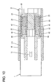
- a leading side for the receptacle front part 11A of the receptacle 11 at least partly enters the spring accommodating portions 23 to be able to build up a biasing force, preferably compress the springs 50 (see FIG. 11), upon coming substantially into contact with the pressing portions 60 preferably after passing the sealing ring 30 as shown in FIG. 10.
- the stopper piece 38 starts returning while being united with the lock arm 24 when the two connector housings 1, 10 reach the substantially properly connected state.
- the main stopper portion 41 is displaced, preferably pushed up or outwardly, by the locking projection 13, whereby the stopper piece 38 is forcibly displaced in such a direction DD (disengaging direction) as to disengage the main stopper portion 41 from the locking hole 32.
- DD disengaging direction
- the auxiliary stopper portion 37 located at or close to the front end of the slider 20 moves onto the upper or outer surface of the front end of the lock arm 24 as shown in FIG. 5, thereby preventing the resilient deformation of the lock arm 24.
- the stopper piece 38 resiliently at least partly returns to at least partly accommodate the main stopper portion 41 into the escaping hole 33 and to engage the protrusions 42 with the abutting portions 43, whereby the backward movement of the slider 20 is prevented.
- the springs 50 return to their states before the start of the connection of the two connector housings 1, 10.
- the operable portion 39 is first operated, preferably pushed to push the slider 20 toward the advanced position AP.
- the slider 20 is pushed until the front ends of the spring accommodating portions 23 come substantially into contact with the forward-movement preventing surfaces 21 in the arched or bridging portion 17.
- a slanted surface is formed at a lower or inner part of the front surface of the main stopper portion 41, and the front surface of the escaping hole 33 substantially corresponding to this slanted surface is also formed into a slanted surface.
- the main stopper portion 41 can smoothly move onto.
- connection detecting connector for preventing a slider from starting moving during a connecting operation, thereby guaranteeing a proper connection, while forces are accumulated in one or more springs 50 (as a preferred biasing member) during a connecting operation
- upright or normal surfaces of a main stopper portion 41 and a locking hole 32 of a lock arm 24, i.e. the surfaces thereof extending in a direction preferably substantially normal to a retreating direction of a slider 20 (or a connecting direction CD of the connector housings 1, 10) are at least partly opposed to each other.
- the locked state of two connector housings 1, 10 preferably is reinforced, whereas the main stopper portion 41 is forcibly displaced as being pushed up by a locking projection 13 in such a direction as to be disengaged from the locking projection 13. Therefore, the locked state of the two connector housings 1,10 can be securely canceled.
- this embodiment preferably has one or more of the following functions and effects.
- the engagement of the main stopper portion 41 and the locking hole 31 preferably is reinforced, whereas the main stopper portion 41 is forcibly displaced such a direction as to be disengaged from the locking hole 31 as being pushed up by the locking projection 13.
- the main stopper portion 41 and the locking hole 31 can be securely disengaged.
- the opening portion 19 is formed in the upper or outer surface of the arched or bridging portion 17, and the lock arm 24 and the stopper piece 38 are made resiliently deformable in the deforming direction DD or outward at least partly through or into the opening portion 19.
- the lock arm 24 and the stopper piece 38 are resiliently deformed substantially in an accommodating portion, the height of the entire connector can be reduced. Further, since the locked state by the lock arm 24 can be more easily seen, the properly connected state can be better guaranteed.
- the slider 20 comes or may come out of the female connector housing 10.
- one or more, preferably a pair of protrusions 42 are provided on the opposite side surfaces of the slider 20, and one or more, preferably a pair of abutting portions 43 engageable with the respective protrusions 42 are provided on the opposite side walls of the groove portions 22. This can make it difficult for the slider 20 to come out of the female connector housing 10.
- the auxiliary stopper portion 37 located at or close to the front end of the slider 20 prevents the resilient deformation of the lock arm 24 when the two connector housings 1, 10 are properly connected, the locking function by the lock arm 24 can be reinforced.
- the auxiliary stopper portion 37 preferably also reinforces the function of (1) in addition to the locking function. In other words, since the auxiliary stopper portion 37 is engageable with the front end of the lock arm 24 as the lock arm 24 moves onto the locking projection 13 during the connecting operation of the two connector housings 1, 10, the backward movement of the slider 20 can be more strongly prevented.
- the lock arm 24 cannot be disengaged unless the slider 20 is returned to the advanced position AP at the time of separating the two connector housings 1, 10. If the operable portion 39 should be pushed without returning the slider 20, the auxiliary stopper portion 37 is located on the upper surface of the front end of the lock arm 24 and the lock arm 24 cannot be resiliently deformed, wherefore the lock arm 24 cannot be disengaged from the locking projection 13.
Abstract
Description
- The present invention relates to a connection detecting connector and to a connection detecting connector assembly.
- A so-called connection detecting connector capable of detecting that two connector housings have reached a properly connected state is known from
Japanese Unexamined Patent Publication No. 2000-82541 - However, in this connector, the locking surfaces are likely to slip along each other by forming the locking surface into the slanted surface, wherefore the lock arm and the slider may be disengaged regardless of an ongoing connecting process to let the slider start moving. The start of the movement of the slider before the two connector housings reach the properly connected state leads to a misunderstanding that the properly connected state was reached regardless of the ongoing connecting process. Thus, a primary role of the connection detecting connector is lacking.
- The present invention was developed in view of the above problem, and an object thereof is to guarantee a substantially properly connected state by preventing a movable member from starting moving during a connecting process.
- This object is solved according to the invention by the features of the independent claims. Preferred embodiments of the invention are subject of the dependent claims.
- According to the invention, there is provided a connection detecting connector, comprising:
- a connector housing connectable with a mating connector housing,
- the connector housing including:
- a lock arm resiliently deformable to move substantially onto a locking projection of the mating connector housing during a connecting operation of the connector housing with the mating connector housing and returnable towards or to an initial state upon moving over the locking projection when the two connector housings reach a substantially properly connected state, thereby locking the two connector housings in the substantially properly connected state,
- a movable member arranged at a side toward which the lock arm is resiliently deformed, and
- a biasing member provided between the movable member and the connector housing to accumulate a biasing force,
- at least one stopper portion provided in the movable member to be engaged with the resiliently deformed lock arm during the connecting operation to substantially prevent a movement of the lock arm, whereby the biasing member can be operated by the connector housing to accumulate a force, and the lock arm returns to be disengaged from the stopper portion when the substantially properly connected state is reached, whereby the movable member is moved by a restoring force of the biasing member, making it recognizable that the substantially properly connected state was reached, and
- one or more locking surfaces of the stopper portion and the lock arm abut on each other in a state where almost no components of force are created in such a direction as to resiliently deform the lock arm during the connecting operation.
- Accordingly, since the stopper portion provided in the movable member is engaged with the lock arm to prevent a movement of the movable member during the connecting operation, the biasing member is pushed or urged by the connector housing to accumulate a force. During this time, the locking surface(s) of the stopper portion and the lock arm strongly abut on each other. However, since these locking surfaces abut on each other in such a state where almost no components of force are created in the deforming direction of the lock arm, there is no likelihood that the movable member starts moving by being disengaged.
- According to a preferred embodiment of the invention, with the two connector housings substantially properly connected, a receiving portion formed to project from the movable member toward the locking projection is located at the side toward which the lock arm is resiliently deformed and forcibly displaces the movable member in such a direction as to disengage the stopper portion and the lock arm from each other by being urged by the locking projection.
- In the properly connected state, the receiving portion is pushed up by the locking projection to forcibly displace the movable member in such a direction as to disengage the stopper portion and the lock arm from each other. Thus, after the engaged state of the lock arm and the stopper portion is securely canceled and the lock arm resiliently at least partly returns and is engaged with the locking projection to lock the two connector housings in the substantially properly connected state, the movable member moves backward, making it recognizable that the substantially properly connected state was reached.
- Preferably, the movable member comprises a slider movable substantially along connecting and separating directions of the two connector housings.
- Most preferably, the biasing member comprises at least one spring extendible and compressible substantially along the connecting direction of the two connector housings.
- According to a further preferred embodiment of the invention, there is provided a connection detecting connector, comprising:
- two connector housings connectable with each other,
- one connector housing including a locking projection,
- the other connector housing including:
- a lock arm resiliently deformable to move onto the locking projection during a connecting operation of the two connector housings and returnable to an initial state upon moving over the locking projection when the two connector housings reach a properly connected state, thereby locking the two connector housings in the properly connected state,
- a slider movable along connecting and separating directions of the two connector housings and arranged at a side toward which the lock arm is resiliently deformed, and
- a spring provided between the slider and the one connector housing and extendible and compressible along the connecting direction of the two connector housings,
- a stopper portion provided in the slider is engaged with the resiliently deformed lock arm during the connecting operation to prevent a movement of the lock arm, whereby the spring can be pushed by the one connector housing to accumulate a force, and the lock arm returns to be disengaged from the stopper portion when the properly connected state is reached, whereby the slider is moved by a restoring force of the spring, making it recognizable that the properly connected state was reached, and
- locking surfaces of the stopper portion and the lock arm abut on each other in a state where almost no components of force are created in such a direction as to resiliently deform the lock arm during the connecting operation and, with the two connector housings properly connected, a receiving portion formed to project from the slider toward the locking projection is located at the side toward which the lock arm is resiliently deformed and forcibly displaces the slider in such a direction as to disengage the stopper portion and the lock arm from each other by being pushed up by the locking projection.
- Accordingly, since the stopper portion provided in the slider is engaged with the lock arm to prevent a movement of the slider during the connecting operation, the spring is pushed by the one connector housing to accumulate a force. During this time, the locking surfaces of the stopper portion and the lock arm strongly abut on each other. However, since these locking surfaces abut on each other in such a state where almost no components of force are created in the deforming direction of the lock arm, there is no likelihood that the slider starts moving by being disengaged. In the properly connected state, the receiving portion is pushed up by the locking projection to forcibly displace the slider in such a direction as to disengage the stopper portion and the lock arm from each other. Thus, after the engaged state of the lock arm and the stopper portion is securely canceled and the lock arm resiliently returns and is engaged with the locking projection to lock the two connector housings in the properly connected state, the slider moves backward, making it recognizable that the properly connected state was reached.
- Preferably, an accommodating portion for the lock arm and the slider is provided in the other connector housing and formed with an escaping opening extending in a displacing direction of the slider, and the lock arm is resiliently deformed and the slider is displaced through the opening.
- Accordingly, the lock arm and the slider are let to escape outward through the opening formed in the accommodating portion. Thus, as compared to a case where an escaping space is defined in the accommodating portion instead of the opening, the height of the entire connector can be reduced by as much as the escaping space.
- Further preferably, the movable member includes at least one protrusion and engageable with at least one groove portion provided in the mating connector housing to prevent a displacement of the movable member and to permit a movement of the movable member.
- Still further preferably, either one of the slider and the other connector housing includes a protrusion and the other thereof is formed with a groove portion engageable with the protrusion to prevent a displacement of the slider and to permit a movement of the slider.
- Accordingly, since the movable member or slider preferably is exposed to the outside as a result of forming the opening in the accommodating portion, the connector can be constructed such that the movable member or slider is unlikely to come off if the protrusion and the groove portion engageable with each other are provided between the slider and the connector housing.
- Further preferably, the movable member is formed with at least one auxiliary stopper portion to be engaged with the lock arm to prevent a movement of the movable member together with the stopper portion as the lock arm moves onto the locking projection during the connecting operation and to be disengaged from the lock arm as the lock arm at least partly returns when the substantially properly connected state is reached.
- Still further preferably, the auxiliary stopper portion preferably comes to be at least partly located in a deformation space for the lock arm to prevent the resilient deformation of the lock arm as the movable member moves after the substantially properly connected state is reached.
- Most preferably, the slider is formed with an auxiliary stopper portion to be engaged with the lock arm to prevent a movement of the slider together with the stopper portion as the lock arm moves onto the locking projection during the connecting operation and to be disengaged from the lock arm as the lock arm returns when the properly connected state is reached, and the auxiliary stopper portion comes to be located in a deformation space for the lock arm to prevent the resilient deformation of the lock arm as the slider moves after the properly connected state is reached.
- Accordingly, since the movable member (preferably slider) is formed with the auxiliary stopper portion engageable with the lock arm as the lock arm moves onto the locking projection, the lock arm can be (preferably doubly) locked by the stopper portion and the auxiliary stopper portion, thereby more securely avoiding such a situation where the movable member (slider) inadvertently moves during the connecting operation. In the substantially properly connected state, the auxiliary stopper portion is located in the deformation space for the lock arm to prevent the resilient deformation of the lock arm. Therefore, a function of locking the two connector housings in the substantially properly connected state can be more strengthened.
- According to teh invention, there is further provided a connection detecting connector assembly comprising a connection detecting connector according to the invention or a preferred embodiment thereof and a mating connector connectable therewith.
- According to a preferred embodiment of the invention, either one of the movable member and the mating connector housing includes at least one protrusion and the other thereof is formed with at least one groove portion engageable with the protrusion to prevent a displacement of the movable member and to permit a movement of the movable member.
- Preferably, either one of the movable member and the mating connector housing includes at least one protrusion and the other thereof is formed with at least one groove portion engageable with the protrusion to prevent a displacement of the movable member and to permit a movement of the movable member.
- These and other objects, features and advantages of the present invention will become more apparent upon reading of the following detailed description of preferred embodiments and accompanying drawings. It should be understood that even though embodiments are separately described, single features thereof may be combined to additional embodiments.
- FIG. 1 is a section showing a state before a connecting operation of two connector housings is started,
- FIG. 2 is a section showing an intermediate state of the front end of a lock arm moving onto a locking projection during the connecting operation,
- FIG. 3 is a section showing a state where the front end of the lock arm is on the locking projection during the connecting operation,
- FIG. 4 is a section showing a state where a stopper piece is disengaged from the lock arm by being pushed up by the locking projection and the lock arm has at least partly returned with the two connector housings substantially properly connected,
- FIG. 5 is a section showing an intermediate state when a slider moves from an advanced position to a retreated position (RP) with the two connector housings properly connected,
- FIG. 6 is a section showing a state where the slider has moved to the retreated position (RP) with the two connector housings properly connected,
- FIG. 7 is a section showing a state where an operable portion is pushed in the process of separating the two connector housings,
- FIG. 8 is a section showing a state where the two connector housings are separated,
- FIG. 9 is a plan view partly in section showing a state before the connecting operation of the two connector housings is started,
- FIG. 10 is a plan view partly in section showing a state when it is started to push springs during the connecting operation,
- FIG. 11 is a plan view partly in section showing a state where it is completed to push the springs with the two connector housings properly connected,
- FIG. 12 is a plan view partly in section showing a state where the slider is pushed towards or to the retreated position (RP) by reactive forces of the springs with the two connector housings properly connected,
- FIG. 13 is an exploded perspective view of a female connector,
- FIG. 14 is a front view showing a state where the slider is assembled into the female connector housing,
- FIG. 15 is a rear view showing the state of FIG. 14,
- FIG. 16 is a plan view showing the state of FIG. 14,
- FIG. 17 is a plan view of the female connector housing,
- FIG. 18 is a plan view of the slider,
- FIG. 19 is a bottom view of the slider,
- FIG. 20 is a front view of the slider, and
- FIG. 21 is a rear view of the slider.
- One preferred embodiment of the present invention is described with reference to FIGS. 1 to 21.
- A connection detecting connector according to this embodiment is comprised of at least one female connector F and at least one male connector M connectable with each other along a connecting direction CD as shown in FIG. 1. It should be noted that sides of the two
connectors - The male connector M has a
male connector housing 1 made e.g. of a synthetic resin and provided with at least onereceptacle 11 having an open front end. Thereceptacle 11 has a stepped portion at least partly circumferentially formed substantially in an intermediate position (preferably substantially in the middles) of its inner surfaces with respect to forward and backward directions FBD, wherein a front part (preferably substantially half) of thereceptacle 11 before the stepped portion is a receptaclefront part 11A whose wall is thinner than a rear part (preferably substantially the rear half) of thereceptacle 11. One or more, preferably twomale tabs 12 project substantially forward (or substantially along the connecting direction CD) preferably substantially side by side along width direction from or at the back wall of thereceptacle 11. The leading ends of themale tabs 12 are located slightly behind the stepped portion, and a lockingprojection 13 is formed in an widthwise intermediate position (preferably substantially in the widthwise center) of the lateral (upper) surface preferably substantially above or corresponding to the stepped portion. The front surface of the lockingprojection 13 preferably is formed into a guidingsurface 13A steeply sloped up or outward toward the back, the upper surface thereof is formed into a slidingcontact surface 13B moderately sloped down (or inwardly or towards the connector housing 1) toward the back, and the rear surface thereof is formed into a flatconnector locking surface 13C being substantially upright (or normal to the forward and backward directions FBD and/or to the connecting direction CD). - The female connector F is, as shown in FIG. 13, provided with a
female connector housing 10, a slider 20 (as a preferred movable member), preferably a sealingring 30 and aretainer 40. Thefemale connector housing 10 is made e.g. of a synthetic resin and in the form of a block preferably having a substantially rectangular cross section, and includes a (preferably substantially rectangular)tube portion 16 in the form of a receptacle having an open front end and amain body 15 preferably substantially in the form of a block long in forward and backward directions FBD, having a substantially rectangular cross section and at least partly arranged inside the (rectangular)tube portion 16 in such a manner as to penetrate the back wall of the (rectangular)tube portion 16. Aconnection space 18 for at least partly accommodating thereceptacle 11 is defined between the (rectangular)tube portion 16 and themain body 15. When the twoconnector housings front part 11A of thereceptacle 11 can enter preferably up to the back wall of the (rectangular)tube portion 16. - One or more, preferably two
cavities 14 extending substantially in forward and backward directions FBD are formed (preferably substantially side by side along width direction) inside themain body 15. One or more femaleterminal fittings 2 can be at least partly accommodated into therespective cavities 14. Each female terminal fitting 2 is comprised of aterminal connecting portion 27 and awire connecting portion 28, wherein themale tab 12 is connected with theterminal connecting portion 27 preferably by being resiliently squeezed laterally (from below and above) by one ormore contact pieces 29 provided in theterminal connecting portion 27 and thewire connecting portion 28 is connected (preferably is crimped or bent or folded into connection) with a wire W and preferably awaterproof rubber plug 26 to establish an electrical connection. Upon being at least partly inserted into thecavity 14 in an insertion direction, preferably substantially from behind, the female terminal fitting 2 is stopped by afront wall 31 of thecavity 14 so as not to move any further forward and is so retained as not to move backward by a lockingportion 25 resiliently deformably provided at (preferably a front side of) the lateral (bottom) surface of thecavity 14. Theretainer 40 preferably of the front-type is mountable on (preferably the front surface of) themain body 15. When theretainer 40 is mounted on themain body 15, the lateral (bottom) wall of theretainer 40 preferably at least partly enters a deformation space for the lockingportions 25 to prevent the resilient deformation of the lockingportions 25, with the result that the femaleterminal fittings 2 are (preferably doubly) locked. - The sealing
ring 30 for preferably providing hermetic or waterproof sealing between the twoconnector housings main body 15 from front. The sealingring 30 is fittable substantially along the outer circumferential surface in an intermediate position (preferably substantially in the center) of themain body 15 along forward and backward directions FBD. One or more sealing lips of the sealingring 30 are to be held substantially in close contact with the inner surfaces of the receptaclefront part 11A. When theretainer 40 is mounted, the rear end surface of theretainer 40 preferably comes substantially into contact with the front end of the sealingring 30, whereby the sealingring 30 is so retained as not to come out forward. - An arched or bent or bridge-
like portion 17 bulging out upward or outward to define a space communicating with theconnection space 18 is formed on or at the lateral (upper) surface of the (rectangular)tube portion 16, and alock arm 24 and theslider 20 are at least partly accommodated inside or below or radially inwardly from the arched portion 17 (see e.g. FIG. 13). Thisarched portion 17 preferably is formed over a length range extending from the front end of the main body 15 (or close thereto) towards or to the rear end thereof, and anopening portion 19 is formed in the ceiling surface of thearched portion 17 while leaving an front-upper end portion of the (rectangular)tube portion 16. The upper or outer or distal edges of the opposite side walls of thearched portion 17 are set to be higher (or more outward) than the upper or outer end of theslider 20 when theslider 20 is in a substantially parallel posture while being lower or more inward than the upper or outer end of theslider 20 when theslider 20 is in a protected state where it is resiliently deformed by moving onto thelock arm 24. - On the other hand, as shown in FIG. 13, the inner surface of each side wall of the
arched portion 17 has a rear portion (preferably substantially a rear half) thereof cut off or recessed, thereby forming agroove portion 22 extending substantially along forward and backward directions FBD. Thegroove portions 22 can guide the movement of theslider 20 between an advanced position AP (position shown in FIG. 1) and a retracted or retreated position RP (position shown in FIG. 6). Stepped or inwardly projecting surfaces are formed at boundaries between both inner side surfaces of thearched portion 17 and thegroove portions 22 and serve as forward-movement preventing surfaces 21 for preventing a forward movement of theslider 20. In this embodiment, one or more jig insertion holes are so formed in one or more (preferably both) side walls of thearched portion 17 as to extend along the substantially same axis as thegroove portions 22 and to penetrate from the forward-movement preventing surfaces 21 to the front wall of thearched portion 17. A disengaging jig is or can be at least partly inserted into the jig insertion holes to detach theslider 20. An abuttingportion 43 is formed in eachgroove portion 22 to prevent theslider 20 from coming out backward when theslider 20 is at the retreated position RP. - The
lock arm 24 for locking the twoconnector housings main body 15. Thelock arm 24 preferably is long substantially in forward and backward directions FBD substantially in the widthwise center of themain body 15 and/or preferably extends over a length range from the rear end of the arched portion 17 (or close thereto) towards or to the rear end of the main body 15 (or close thereto). Thelock arm 24 can be held in the parallel posture with abase end 24A located near the rear end of the (rectangular)tube portion 16 on the lateral (upper) surface of themain body 15 and the front and rear parts thereof can undergo a seesaw-like resilient deformation. - A locking
hole 32 is formed at a position of thelock arm 24 preferably slightly behind the front end. The front and rear surfaces of the lockinghole 32 are upright flat surfaces (or arranged at an angle different from 0° or 180°, preferably substantially normal to the connecting direction CD). A slanted surface sloped down toward the back is formed at the front end of thelock arm 24, so that the front end of thelock arm 24 can smoothly move onto the lockingprojection 13 during a connecting operation of the twoconnector housings projection 13, the front end of thelock arm 24 slides on the slidingcontact surface 13B and then thelock arm 24 resiliently at least partly returns upon the engagement of the lockingprojection 13 into the lockinghole 32, whereby the twoconnector housings hole 32 and theconnector locking surface 13C. The front end of thelock arm 24 is resiliently deformable through the openingportion 19. - The
slider 20 can be so assembled at least partly into the arched portion 17 (corresponding to a preferred accommodating portion) as to at least partly cover thelock arm 24 from above or from outside. Thisslider 20 waits on standby at the advanced position AP during the connecting operation of the twoconnector housings connector housings slider 20 is formed into a unit by having a biasing member (preferably comprising one or more springs) at least partly incorporated therein, and can be assembled into thearched portion 17 as this unit. - Specifically, as shown in FIGS. 18 and 20, the
slider 20 is an integral or unitary assembly of abase plate 34 preferably having a substantially rectangular shape long in forward and backward directions FBD and one or more, preferably a pair ofspring accommodating portions 23 formed in the lower or inner surface of a rear portion (preferably a substantially rear half) of thebase plate 34 preferably at the substantially opposite widthwise ends. One ormore protrusions 42 are formed on the outer one(s) of the widthwise end surfaces of the respectivespring accommodating portions 23, and are slidably at least partly fittable into thegroove portions 22 when theslider 20 is assembled into thefemale connector housing 10. The front surface of eachprotrusion 42 is formed into a slanted surface moderately sloped down or inwardly toward the front, and the rear surface thereof is formed into a substantially upright or normal flat surface. The one ormore protrusions 42 prevent theslider 20 from coming out backward by coming into engagement with the one or more abuttingportions 43 provided in the aforementioned one ormore groove portions 22. - FIG. 18 is a plan view of the
slider 20. Identified by 35 are one or more protection walls extending substantially in forward and backward directions FBD and downward direction at or close to the substantially opposite widthwise edges of thebase plate 34, and a (preferably substantially rectangular) opening is formed in the outer or upper surface of thebase plate 34. A framed edge preferably is formed to project at the peripheral edge of this opening except the front edge. A stopper piece 38 (corresponding to a preferred stopper portion) extends substantially forward from the rear edge of the opening in such a manner as to be resiliently deformable upward and downward or laterally or in a direction intersecting the forward and backward directions FBD and/or the connecting direction CD. Amain stopper portion 41 is formed to project from the inner surface of the leading end of thestopper piece 38. Themain stopper portion 41 is to be engaged with the rear surface of the lockinghole 32 of thelock arm 24 when theslider 20 is at the advanced position AP, thereby preventing theslider 20 from moving backward. During the connecting operation of the twoconnector housings lock arm 24 is resiliently deformed upon moving onto the lockingprojection 13. However, since thestopper piece 38 is resiliently deformable by moving onto the upper surface of thelock arm 24 while themain stopper portion 41 is held engaged with the lockinghole 32 of thelock arm 24, theslider 20 is prevented from moving from the advanced position AP to the retreated position RP (see FIGS. 2 and 3). The front surface of themain stopper portion 41 preferably is formed into a slanted surface sloped down or inward toward the back, whereas the rear surface thereof is formed into a substantially upright or normal flat surface. The movement of theslider 20 is securely prevented by the abutment of the upright or normal rear surface of themain stopper portion 41 and the upright or normal rear surface of the lockinghole 32 of thelock arm 24. Themain stopper portion 41 is located above the lockingprojection 13 with the twoconnector housings lock arm 24 at least partly returns, themain stopper portion 41 is pushed in a disengaging direction DD (up or outward) by the lockingprojection 13 to forcibly disengage thestopper piece 38 and the lockinghole 32 of thelock arm 24 from each other (see FIG. 4). When themain stopper portion 41 and the lockinghole 32 of thelock arm 24 are disengaged, theslider 20 moves from the advanced position AP towards or to the retreated position RP, whereby themain stopper portion 41 is at least partly accommodated into an escapinghole 33 located slightly behind the lockinghole 32 of thelock arm 24 and thestopper piece 38 resiliently at least partly returns (see FIG. 6) in a direction substantially opposite to the disengaging direction DD. - An
auxiliary stopper portion 37 is formed to couple or bridge or span between the twoprotection walls 35 at or close to the front side of the opening in thebase plate 34. Theauxiliary stopper portion 37 preferably is located before the leading end of thelock arm 24 to permit the resilient deformation of thelock arm 24 when theslider 20 is at the advanced position AP. When being resiliently deformed during the connecting operation, thelock arm 24 comes substantially into engagement with the rear and/or inner surface of theauxiliary stopper portion 37, thereby being (preferably doubly) prevented from moving in cooperation with themain stopper portion 41. Theauxiliary stopper portion 37 is located below (or radially inwardly of) the lower surface of thearched portion 17 to permit the resilient deformation of thelock arm 24 when theslider 20 is at the advanced position AP. When theslider 20 is at the retreated position RP, theauxiliary stopper portion 37 is located above (or radially outward of) the upper or outer surface of the front end of thelock arm 24 to prevent or limit the resilient deformation of thelock arm 24, thereby reinforcing a locking function (see FIG. 6). - An
operable portion 39 used to separate the twoconnector housings connector housing 1 at a position of (or close to) the rear surface of thebase plate 34 preferably substantially between the twospring accommodating portions 23. One ormore contact portions 36 to be held substantially in contact with the upper or outer surface of the rear end of thelock arm 24 when thelock arm 24 is substantially in the parallel posture are provided at a front and/or a rear positions of the lower surface of theoperable portion 39 near the rear end. Therear contact portion 36 preferably is distanced backward from thelock arm 24, but thefront contact portion 36 is or can be kept substantially in contact with thelock arm 24. Upon separating the twoconnector housings slider 20 is operated, preferably substantially pushed forward. In order to plainly show or indicate a pushing direction to an operator, an arrow-shaped projection whose front end is faced forward preferably is formed on the upper surface of theoperable portion 39. It should be noted that this projection preferably also functions as an antislip e.g. when being operated or pushed by the finger. - One or more, preferably a pair of
spring accommodating portions 23 are disposed at a specified (predetermined or predeterminable) distance from each other so that thelock arm 24 preferably can be at least partly arranged close thereto or therebetween upon assembling thespring accommodating portions 23 into thefemale connector housing 10. When thespring accommodating portions 23 are assembled into thefemale connector housing 10, front portions (preferably substantially front halves) thereof at least partly enter the (rectangular)tube portion 16 to be located in an entrance space for thereceptacle front part 11 A of thereceptacle 11. - The spring
accommodating portions 23 are formed such that the springs 50 (as preferred biasing members) can be assembled preferably substantially from front and at least partly accommodated to elongate and compress substantially in forward and backward directions FBD and/or substantially along the connecting direction CD. One or morepressing portions 60 are fitted into the front ends of thesprings 50. With thesprings 50 at least partly accommodated in thespring accommodating portions 23 together with thepressing portions 60, thepressing portions 60 prevent thesprings 50 from coming out by coming into contact with the inner surfaces of the front walls of thespring accommodating portions 23. On the other hand, one or more cuts are made (preferably substantially up to the substantial centers of the spring accommodating portions 23) with respect to forward and backward directions FBD in the lower parts of front portions (preferably substantially front halves) of thespring accommodating portions 23. Specifically, substantially front lower parts of thesprings 50 are located in the entrance space of thereceptacle front part 11 A of thereceptacle 11 and at least partly exposed. During the connecting operation of the twoconnector housings front part 11A of thereceptacle 11 at least partly enters thespring accommodating portions 23 to be able to build up a biasing force, preferably compress the springs 50 (see FIG. 11), upon coming substantially into contact with thepressing portions 60 preferably after passing the sealingring 30 as shown in FIG. 10. - Next, functions of this embodiment constructed as above are described.
- First, when the
female connector housing 10 is at least partly inserted substantially along the connecting direction CD into themale connector housing 1 to connect the twoconnector housings lock arm 24 moves onto the slidingcontact surface 13B after coming substantially into contact with the guidingsurface 13A of the lockingprojection 13. On the other hand, the leading end of the receptaclefront part 11A of thereceptacle 11 starts touching thepressing portions 60. At this time, since theslider 20 and thelock arm 24 are united or coupled by the engagement of both themain stopper portion 41 and theauxiliary stopper portion 37 of theslider 20 with thelock arm 24, one or more, preferably bothsprings 50 can be pushed to accumulate forces as the twoconnector housings springs 50 are compressed to a certain extent at this time, thefemale connector housing 1 is pushed out of thefemale connector housing 10 by spring forces e.g. if the connecting operation should be interrupted at this point of time. This can prevent the male and female terminal fittings from being left incompletely electrically connected. - As shown in FIG. 7, the
stopper piece 38 starts returning while being united with thelock arm 24 when the twoconnector housings main stopper portion 41 is displaced, preferably pushed up or outwardly, by the lockingprojection 13, whereby thestopper piece 38 is forcibly displaced in such a direction DD (disengaging direction) as to disengage themain stopper portion 41 from the lockinghole 32. If themain stopper portion 41 and the lockinghole 32 are disengaged in this way, thelock arm 24 is separated from thestopper piece 38 and returns towards or to its initial posture to be substantially engaged with the lockingprojection 13, with the result that twoconnector housings more springs 50 are maximally compressed between the front end of thereceptacle front part 11 A and the rear surfaces of thespring accommodating portions 23 to accumulate forces as shown in FIG. 11 when or immediately after thelock arm 24 and thestopper piece 38 start returning. When the twoconnector housings main stopper portion 41 and the lockinghole 32 are disengaged from each other, wherefore theslider 20 retreats substantially at a stroke. As a result, an operator can notice that the twoconnector housings - When the
slider 20 moves from the advanced position AP towards or to the retreated position RP by the biasing force of the biasing member, preferably by the reactive forces of thesprings 50, theauxiliary stopper portion 37 located at or close to the front end of theslider 20 moves onto the upper or outer surface of the front end of thelock arm 24 as shown in FIG. 5, thereby preventing the resilient deformation of thelock arm 24. When theslider 20 reaches the retreated position RP in this way, thestopper piece 38 resiliently at least partly returns to at least partly accommodate themain stopper portion 41 into the escapinghole 33 and to engage theprotrusions 42 with the abuttingportions 43, whereby the backward movement of theslider 20 is prevented. On the other hand, as shown in FIG. 12, thesprings 50 return to their states before the start of the connection of the twoconnector housings - Next, the case of separating the two
connector housings connector housings operable portion 39 is first operated, preferably pushed to push theslider 20 toward the advanced position AP. At this time, theslider 20 is pushed until the front ends of thespring accommodating portions 23 come substantially into contact with the forward-movement preventing surfaces 21 in the arched or bridgingportion 17. A slanted surface is formed at a lower or inner part of the front surface of themain stopper portion 41, and the front surface of the escapinghole 33 substantially corresponding to this slanted surface is also formed into a slanted surface. Thus, themain stopper portion 41 can smoothly move onto. When theslider 20 reaches the advanced position AP, thestopper piece 38 is resiliently deformed again in the disengaging direction DD, as shown in FIG. 4, and themain stopper portion 41 moves onto the lockingprojection 13. Simultaneously, bothcontact portions 36 at the rear side of the lower surface of theoperable portion 39 move onto thelock arm 24. As described above, theoperable portion 39 is pushed down or inwardly while theslider 20 is pushed towards or to the advanced position AP. Then, the rear end of thelock arm 24 is pushed down or inwardly by thecontact portions 36, wherefore the front end of thelock arm 24 is conversely lifted up or deformed in the deforming direction DD to be disengaged from the lockingprojection 13. As a result, themale connector housing 1 is pushed out of thefemale connector housing 10 by the biasing or spring forces, thereby separating the twoconnector housings - Accordingly, to provide a connection detecting connector for preventing a slider from starting moving during a connecting operation, thereby guaranteeing a proper connection, while forces are accumulated in one or more springs 50 (as a preferred biasing member) during a connecting operation, upright or normal surfaces of a
main stopper portion 41 and alocking hole 32 of alock arm 24, i.e. the surfaces thereof extending in a direction preferably substantially normal to a retreating direction of a slider 20 (or a connecting direction CD of theconnector housings 1, 10), are at least partly opposed to each other. Thus, even if spring forces act, substantially no components of force are created in such a direction DD as to disengage theslider 20. Therefore, there is no likelihood that a locked state of twoconnector housings slider 20 move backward or towards the retreated position RP during the connecting operation of the twoconnector housings connector housings main stopper portion 41 is forcibly displaced as being pushed up by a lockingprojection 13 in such a direction as to be disengaged from the lockingprojection 13. Therefore, the locked state of the twoconnector housings - As described above, this embodiment preferably has one or more of the following functions and effects.
- While forces are accumulated in the biasing member, preferably in the
springs 50, during the connecting operation, upright surfaces of the main stopper portion 41 (or surfaces substantially perpendicular to the connecting direction CD) and the lockinghole 32 of thelock arm 24, i.e. the surfaces thereof extending in a direction substantially normal to the retreating direction of theslider 20, are substantially opposed to each other. Thus, even if the spring forces act, no components of force are created in such a direction as to disengage theslider 20 from thelock arm 24. Accordingly, there is no likelihood that theslider 20 moves backward or towards the retreated position RP upon disengaging themain stopper portion 41 and the lockinghole 32 from each other during the connecting operation of the twoconnector housings main stopper portion 41 and the lockinghole 31 preferably is reinforced, whereas themain stopper portion 41 is forcibly displaced such a direction as to be disengaged from the lockinghole 31 as being pushed up by the lockingprojection 13. Thus, themain stopper portion 41 and the lockinghole 31 can be securely disengaged. - The opening
portion 19 is formed in the upper or outer surface of the arched or bridgingportion 17, and thelock arm 24 and thestopper piece 38 are made resiliently deformable in the deforming direction DD or outward at least partly through or into the openingportion 19. Thus, as compared to a construction in which thelock arm 24 and thestopper piece 38 are resiliently deformed substantially in an accommodating portion, the height of the entire connector can be reduced. Further, since the locked state by thelock arm 24 can be more easily seen, the properly connected state can be better guaranteed. - As a result of forming the opening
portion 19 in order to reduce the height of the connector, there is a possibility that theslider 20 comes or may come out of thefemale connector housing 10. However, one or more, preferably a pair ofprotrusions 42 are provided on the opposite side surfaces of theslider 20, and one or more, preferably a pair of abuttingportions 43 engageable with therespective protrusions 42 are provided on the opposite side walls of thegroove portions 22. This can make it difficult for theslider 20 to come out of thefemale connector housing 10. - Since the
auxiliary stopper portion 37 located at or close to the front end of theslider 20 prevents the resilient deformation of thelock arm 24 when the twoconnector housings lock arm 24 can be reinforced. Theauxiliary stopper portion 37 preferably also reinforces the function of (1) in addition to the locking function. In other words, since theauxiliary stopper portion 37 is engageable with the front end of thelock arm 24 as thelock arm 24 moves onto the lockingprojection 13 during the connecting operation of the twoconnector housings slider 20 can be more strongly prevented. - The
lock arm 24 cannot be disengaged unless theslider 20 is returned to the advanced position AP at the time of separating the twoconnector housings operable portion 39 should be pushed without returning theslider 20, theauxiliary stopper portion 37 is located on the upper surface of the front end of thelock arm 24 and thelock arm 24 cannot be resiliently deformed, wherefore thelock arm 24 cannot be disengaged from the lockingprojection 13. - The present invention is not limited to the above described and illustrated embodiment. For example, the following embodiments are also embraced by the technical scope of the present invention as defined by the claims. Beside the following embodiments, various changes can be made without departing from the scope and spirit of the present invention as defined by the claims.
- (1) Although the main stopper portion functions both to prevent the retreating movement of the slider and to be disengaged from the lock arm by being pushed in the foregoing embodiment, a spot or portion different from the main stopper portion may be set to be pushed up.
- (2) Although the compression spring(s) is/are used as the preferred biasing member in the foregoing embodiment, tension spring(s), resilient rod(s), leaf spring(s) or the like may be used as such.
-
- 1
- male connector housing
- 10
- female connector housing
- 13
- locking projection
- 17
- arched portion (its interior is an accommodating portion)
- 19
- opening portion (opening)
- 20
- slider
- 22
- groove portion
- 24
- lock arm
- 37
- auxiliary stopper portion
- 38
- stopper piece (stopper portion)
- 41
- main stopper portion (receiving portion)
- 42
- protrusion
- 50
- spring
Claims (10)
- A connection detecting connector, comprising:a connector housing (10) connectable with a mating connector housing (1), the connector housing (10) including:wherein:a lock arm (24) resiliently deformable to move substantially onto a locking projection (13) of the mating connector housing (1) during a connecting operation of the connector housing (10) with the mating connector housing (1) and returnable towards or to an initial state upon moving over the locking projection (13) when the two connector housings (10, 1) reach a substantially properly connected state, thereby locking the two connector housings (10, 1) in the substantially properly connected state,a movable member (20) arranged at a side toward which the lock arm (24) is resiliently deformed, anda biasing member (50) provided between the movable member (20) and the connector housing (10) to accumulate a biasing force,at least one stopper portion (38) provided in the movable member (20) to be engaged with the resiliently deformed lock arm (24) during the connecting operation to substantially prevent a movement of the lock arm (24), whereby the biasing member (50) can be operated by the connector housing (10) to accumulate a force, and the lock arm (24) returns to be disengaged from the stopper portion (38) when the substantially properly connected state is reached, whereby the movable member (20) is moved by a restoring force of the biasing member (50), making it recognizable that the substantially properly connected state was reached, andone or more locking surfaces of the stopper portion (38) and the lock arm (24) abut on each other in a state where almost no components of force are created in such a direction as to resiliently deform the lock arm (24) during the connecting operation.
- A connection detecting connector according to claim 1, wherein with the two connector housings (10, 1) substantially properly connected, a receiving portion (41) formed to project from the movable member (20) toward the locking projection (13) is located at the side toward which the lock arm (24) is resiliently deformed and forcibly displaces the movable member (50) in such a direction (DD) as to disengage the stopper portion (38) and the lock arm (24) from each other by being urged by the locking projection (13).
- A connection detecting connector according to one or more of the preceding claims, wherein the movable member (20) comprises a slider (20) movable substantially along connecting and separating directions (CD) of the two connector housings (10, 1).
- A connection detecting connector according to one or more of the preceding claims, wherein the biasing member (50) comprises at least one spring (50) extendible and compressible substantially along the connecting direction (CD) of the two connector housings (10, 1).
- A connection detecting connector according to one or more of the preceding claims, wherein the movable member (20) includes at least one protrusion (42) and engageable with at least one groove portion (22) provided in the mating connector housing (1) to prevent a displacement of the movable member (20) and to permit a movement of the movable member (20).
- A connection detecting connector according to one or more of the preceding claims, wherein the movable member (20) is formed with at least one auxiliary stopper portion (37) to be engaged with the lock arm (24) to prevent a movement of the movable member (24) together with the stopper portion (38) as the lock arm (24) moves onto the locking projection (13) during the connecting operation and to be disengaged from the lock arm (24) as the lock arm (24) at least partly returns when the substantially properly connected state is reached.
- A connection detecting connector according to claim 6, wherein the auxiliary stopper portion (37) preferably comes to be at least partly located in a deformation space for the lock arm (24) to prevent the resilient deformation of the lock arm (24) as the movable member (50) moves after the substantially properly connected state is reached.
- A connection detecting connector assembly comprising a connection detecting connector according to one or more of the preceding claims and a mating connector connectable therewith.
- A connection detecting connector assembly according to claim 8, wherein either one of the movable member (20) and the mating connector housing (1) includes at least one protrusion (42) and the other thereof is formed with at least one groove portion (22) engageable with the protrusion (42) to prevent a displacement of the movable member (20) and to permit a movement of the movable member (20).
- A connection detecting connector assembly according to claim 9, wherein either one of the movable member (20) and the mating connector housing (1) includes at least one protrusion (42) and the other thereof is formed with at least one groove portion (22) engageable with the protrusion (42) to prevent a displacement of the movable member (20) and to permit a movement of the movable member (20).
Applications Claiming Priority (1)
| Application Number | Priority Date | Filing Date | Title |
|---|---|---|---|
| JP2005071259A JP4419875B2 (en) | 2005-03-14 | 2005-03-14 | Mating detection connector |
Publications (2)
| Publication Number | Publication Date |
|---|---|
| EP1703599A1 true EP1703599A1 (en) | 2006-09-20 |
| EP1703599B1 EP1703599B1 (en) | 2009-08-12 |
Family
ID=36011117
Family Applications (1)
| Application Number | Title | Priority Date | Filing Date |
|---|---|---|---|
| EP06003270A Expired - Fee Related EP1703599B1 (en) | 2005-03-14 | 2006-02-17 | A connection detecting connector and a connection detecting connector assembly |
Country Status (3)
| Country | Link |
|---|---|
| EP (1) | EP1703599B1 (en) |
| JP (1) | JP4419875B2 (en) |
| DE (1) | DE602006008371D1 (en) |
Cited By (13)
| Publication number | Priority date | Publication date | Assignee | Title |
|---|---|---|---|---|
| WO2010032088A1 (en) * | 2008-09-16 | 2010-03-25 | Fci | Electrical connector assembly |
| US7901235B2 (en) | 2007-03-22 | 2011-03-08 | Edwards Lifesciences Corporation | Releasably locking auto-aligning fiber optic connector |
| EP2426790A1 (en) * | 2010-09-03 | 2012-03-07 | Sumitomo Wiring Systems, Ltd. | Connector and connector assembly |
| ITTO20120904A1 (en) * | 2012-10-16 | 2014-04-17 | Tyco Electronics Amp Italia Srl | ELECTRIC CONNECTOR WITH CONNECTOR POSITION INSURANCE ELEMENT |
| WO2015154747A1 (en) | 2014-04-10 | 2015-10-15 | HARTING Electronics GmbH | Air-tight plug connector and method for the use thereof |
| CN105191010A (en) * | 2013-05-08 | 2015-12-23 | 住友电装株式会社 | Connector |
| WO2016012006A1 (en) | 2014-07-24 | 2016-01-28 | HARTING Electronics GmbH | Plug-in connector having a low-wear sealing function |
| CN105406283A (en) * | 2014-09-04 | 2016-03-16 | 德尔福技术有限公司 | Connector With Connector Position Assurance Device |
| FR3034575A1 (en) * | 2015-04-03 | 2016-10-07 | Yazaki Corp | CONNECTOR WITH SLIDE AND CONNECTOR ASSEMBLY STRUCTURE |
| US9515410B2 (en) | 2013-05-08 | 2016-12-06 | Sumitomo Wiring Systems, Ltd. | Connector with a slider releasably locked to a housing by a resilient stopper having two points of support for resilient deflection |
| WO2017220073A1 (en) * | 2016-06-22 | 2017-12-28 | HARTING Electronics GmbH | Plug connector |
| CN110350362A (en) * | 2018-04-05 | 2019-10-18 | 德尔福技术有限责任公司 | Electric connector with connector lock |
| CN111448720A (en) * | 2017-12-26 | 2020-07-24 | 住友电装株式会社 | Connector with a locking member |
Families Citing this family (17)
| Publication number | Priority date | Publication date | Assignee | Title |
|---|---|---|---|---|
| JP4826501B2 (en) * | 2007-02-23 | 2011-11-30 | 住友電装株式会社 | connector |
| EP2020706B1 (en) | 2007-08-01 | 2011-10-26 | Sumitomo Wiring Systems, Ltd. | A connector, connector assembly and connection method |
| JP5653150B2 (en) | 2010-09-16 | 2015-01-14 | 矢崎総業株式会社 | Half-mating prevention connector |
| KR101723327B1 (en) * | 2013-05-08 | 2017-04-04 | 스미토모 덴소 가부시키가이샤 | Connector |
| JP5999535B2 (en) * | 2013-05-08 | 2016-10-05 | 住友電装株式会社 | connector |
| JP2016062793A (en) | 2014-09-19 | 2016-04-25 | 住友電装株式会社 | connector |
| JP6344204B2 (en) * | 2014-11-05 | 2018-06-20 | 住友電装株式会社 | connector |
| JP2016091819A (en) * | 2014-11-05 | 2016-05-23 | 住友電装株式会社 | connector |
| JP6311573B2 (en) * | 2014-11-05 | 2018-04-18 | 住友電装株式会社 | connector |
| JP6435849B2 (en) | 2014-12-22 | 2018-12-12 | 住友電装株式会社 | connector |
| JP6447100B2 (en) * | 2014-12-22 | 2019-01-09 | 住友電装株式会社 | connector |
| JP6432335B2 (en) * | 2014-12-22 | 2018-12-05 | 住友電装株式会社 | connector |
| JP6327521B2 (en) | 2014-12-22 | 2018-05-23 | 住友電装株式会社 | connector |
| KR101636502B1 (en) * | 2015-05-08 | 2016-07-06 | 케이유엠 유한회사 | Anti vibration type connector |
| JP6287987B2 (en) * | 2015-07-22 | 2018-03-07 | 住友電装株式会社 | connector |
| KR101800275B1 (en) * | 2016-11-11 | 2017-12-21 | 케이유엠 유한회사 | High frequency connector assembly |
| JP7386523B2 (en) | 2020-02-06 | 2023-11-27 | 日本圧着端子製造株式会社 | connector lock mechanism |
Citations (7)
| Publication number | Priority date | Publication date | Assignee | Title |
|---|---|---|---|---|
| US5820399A (en) * | 1996-08-06 | 1998-10-13 | Yazaki Corporation | Connector fitting construction |
| US6027364A (en) * | 1997-04-11 | 2000-02-22 | Yazaki Corporation | Connector fitting construction with side ribs and corresponding side rib-receiving portions |
| EP0981185A2 (en) * | 1998-08-20 | 2000-02-23 | Sumitomo Wiring Systems, Ltd. | Fitting detecting connector |
| JP2000082541A (en) | 1998-09-07 | 2000-03-21 | Sumitomo Wiring Syst Ltd | Fitting detecting connector |
| US6095843A (en) * | 1997-09-09 | 2000-08-01 | Yazaki Corporation | Connector fitting construction |
| US6386898B1 (en) * | 1998-08-03 | 2002-05-14 | Yazaki Corporation | Connector fitting construction |
| US20020132510A1 (en) * | 1999-04-28 | 2002-09-19 | Yazaki Corporation | Connector fitting structure |
-
2005
- 2005-03-14 JP JP2005071259A patent/JP4419875B2/en not_active Expired - Fee Related
-
2006
- 2006-02-17 DE DE602006008371T patent/DE602006008371D1/en active Active
- 2006-02-17 EP EP06003270A patent/EP1703599B1/en not_active Expired - Fee Related
Patent Citations (7)
| Publication number | Priority date | Publication date | Assignee | Title |
|---|---|---|---|---|
| US5820399A (en) * | 1996-08-06 | 1998-10-13 | Yazaki Corporation | Connector fitting construction |
| US6027364A (en) * | 1997-04-11 | 2000-02-22 | Yazaki Corporation | Connector fitting construction with side ribs and corresponding side rib-receiving portions |
| US6095843A (en) * | 1997-09-09 | 2000-08-01 | Yazaki Corporation | Connector fitting construction |
| US6386898B1 (en) * | 1998-08-03 | 2002-05-14 | Yazaki Corporation | Connector fitting construction |
| EP0981185A2 (en) * | 1998-08-20 | 2000-02-23 | Sumitomo Wiring Systems, Ltd. | Fitting detecting connector |
| JP2000082541A (en) | 1998-09-07 | 2000-03-21 | Sumitomo Wiring Syst Ltd | Fitting detecting connector |
| US20020132510A1 (en) * | 1999-04-28 | 2002-09-19 | Yazaki Corporation | Connector fitting structure |
Cited By (31)
| Publication number | Priority date | Publication date | Assignee | Title |
|---|---|---|---|---|
| US7901235B2 (en) | 2007-03-22 | 2011-03-08 | Edwards Lifesciences Corporation | Releasably locking auto-aligning fiber optic connector |
| CN102187529A (en) * | 2008-09-16 | 2011-09-14 | Fci公司 | Electrical connector assembly |
| CN102187529B (en) * | 2008-09-16 | 2013-07-31 | 富加宜汽车控股公司 | Electrical connector assembly |
| WO2010032088A1 (en) * | 2008-09-16 | 2010-03-25 | Fci | Electrical connector assembly |
| CN102437475B (en) * | 2010-09-03 | 2015-10-21 | 住友电装株式会社 | Connector and connector assembly |
| EP2426790A1 (en) * | 2010-09-03 | 2012-03-07 | Sumitomo Wiring Systems, Ltd. | Connector and connector assembly |
| CN102437475A (en) * | 2010-09-03 | 2012-05-02 | 住友电装株式会社 | Connector and connector assembly |
| US8449313B2 (en) | 2010-09-03 | 2013-05-28 | Sumitomo Wiring Systems, Ltd. | Connector and connector assembly |
| CN104798263B (en) * | 2012-10-16 | 2017-03-29 | 泰科电子(Amp)意大利公司 | The electric connector of element is guaranteed with connector positioning |
| WO2014060229A1 (en) * | 2012-10-16 | 2014-04-24 | Tyco Electronics Amp Italia S.R.L | Electrical connector with connector position assurance element |
| CN104798263A (en) * | 2012-10-16 | 2015-07-22 | 泰科电子(Amp)意大利公司 | Electrical connector with connector position assurance element |
| ITTO20120904A1 (en) * | 2012-10-16 | 2014-04-17 | Tyco Electronics Amp Italia Srl | ELECTRIC CONNECTOR WITH CONNECTOR POSITION INSURANCE ELEMENT |
| US9490576B2 (en) | 2012-10-16 | 2016-11-08 | Tyco Electronics Amp Italia S.R.L. | Electrical connector with connector position assurance element |
| US9515410B2 (en) | 2013-05-08 | 2016-12-06 | Sumitomo Wiring Systems, Ltd. | Connector with a slider releasably locked to a housing by a resilient stopper having two points of support for resilient deflection |
| CN105191010A (en) * | 2013-05-08 | 2015-12-23 | 住友电装株式会社 | Connector |
| CN105191010B (en) * | 2013-05-08 | 2017-08-25 | 住友电装株式会社 | Connector |
| US9543697B2 (en) | 2013-05-08 | 2017-01-10 | Sumitomo Wiring Systems, Ltd. | Connector having a housing with a fitting tube with guide walls with a lock arm inbettween |
| WO2015154747A1 (en) | 2014-04-10 | 2015-10-15 | HARTING Electronics GmbH | Air-tight plug connector and method for the use thereof |
| DE102014105144A1 (en) | 2014-04-10 | 2015-10-15 | HARTING Electronics GmbH | Airtight connector and method of use |
| WO2016012006A1 (en) | 2014-07-24 | 2016-01-28 | HARTING Electronics GmbH | Plug-in connector having a low-wear sealing function |
| DE102014110466A1 (en) | 2014-07-24 | 2016-01-28 | HARTING Electronics GmbH | Connector with low-wear sealing function |
| DE102014110466B4 (en) | 2014-07-24 | 2023-02-02 | HARTING Electronics GmbH | Connector with a low-wear sealing function and a device consisting of a connector and a mating connector |
| CN105406283A (en) * | 2014-09-04 | 2016-03-16 | 德尔福技术有限公司 | Connector With Connector Position Assurance Device |
| FR3034575A1 (en) * | 2015-04-03 | 2016-10-07 | Yazaki Corp | CONNECTOR WITH SLIDE AND CONNECTOR ASSEMBLY STRUCTURE |
| WO2017220073A1 (en) * | 2016-06-22 | 2017-12-28 | HARTING Electronics GmbH | Plug connector |
| CN109417247A (en) * | 2016-06-22 | 2019-03-01 | 浩亭电子有限公司 | Connectors |
| US10587078B2 (en) | 2016-06-22 | 2020-03-10 | HARTING Electronics GmbH | Plug connector |
| CN111448720A (en) * | 2017-12-26 | 2020-07-24 | 住友电装株式会社 | Connector with a locking member |
| CN111448720B (en) * | 2017-12-26 | 2021-12-07 | 住友电装株式会社 | Connector with a locking member |
| CN110350362A (en) * | 2018-04-05 | 2019-10-18 | 德尔福技术有限责任公司 | Electric connector with connector lock |
| CN110350362B (en) * | 2018-04-05 | 2020-10-20 | 德尔福技术有限责任公司 | Electrical connector with connector lock |
Also Published As
| Publication number | Publication date |
|---|---|
| JP4419875B2 (en) | 2010-02-24 |
| EP1703599B1 (en) | 2009-08-12 |
| DE602006008371D1 (en) | 2009-09-24 |
| JP2006253073A (en) | 2006-09-21 |
Similar Documents
| Publication | Publication Date | Title |
|---|---|---|
| EP1703599B1 (en) | A connection detecting connector and a connection detecting connector assembly | |
| US6688907B2 (en) | Connector and a connector assembly | |
| EP1764879B1 (en) | A connector, a connector assembly and an assembling method thereof | |
| EP2637261B1 (en) | Connector, connector assembly and assembling method therefor | |
| EP2362498B1 (en) | Male and female connectors and electrical connector including the same | |
| EP1571734B1 (en) | Connector apparatus with a mating detecting member called connector position assurance | |
| EP1638175A2 (en) | A connector and a connector assembly | |
| EP2637262A1 (en) | Connector, connector assembly and assembling/disassembling method therefor | |
| EP1054481A1 (en) | A connector | |
| US20040203287A1 (en) | Connector and a method of assembling such connector | |
| US8231401B2 (en) | Connector | |
| JP2007305541A (en) | Connector | |
| KR20080046566A (en) | Electronic connector | |
| US6811437B2 (en) | Connector and method of mounting it | |
| JP2002056933A (en) | Connector | |
| EP1986288B1 (en) | A shorting terminal, a connector and an assembling method therefor | |
| JP2001085111A (en) | Connector | |
| US6786754B2 (en) | Connector and a connector assembly | |
| JP2002246110A (en) | Connector | |
| US6641437B2 (en) | Connector | |
| JP4304474B2 (en) | connector | |
| US6685506B1 (en) | Connector and a method for connecting such connector with a mating connector | |
| US7431596B2 (en) | Connector assembly with mold removal hole | |
| US20030186579A1 (en) | Connector and a connector assembly | |
| EP1801926B1 (en) | A connetor and connector assembly |
Legal Events
| Date | Code | Title | Description |
|---|---|---|---|
| PUAI | Public reference made under article 153(3) epc to a published international application that has entered the european phase |
Free format text: ORIGINAL CODE: 0009012 |
|
| 17P | Request for examination filed |
Effective date: 20060223 |
|
| AK | Designated contracting states |
Kind code of ref document: A1 Designated state(s): AT BE BG CH CY CZ DE DK EE ES FI FR GB GR HU IE IS IT LI LT LU LV MC NL PL PT RO SE SI SK TR |
|
| AX | Request for extension of the european patent |
Extension state: AL BA HR MK YU |
|
| AKX | Designation fees paid |
Designated state(s): DE FR |
|
| 17Q | First examination report despatched |
Effective date: 20070726 |
|
| GRAP | Despatch of communication of intention to grant a patent |
Free format text: ORIGINAL CODE: EPIDOSNIGR1 |
|
| GRAS | Grant fee paid |
Free format text: ORIGINAL CODE: EPIDOSNIGR3 |
|
| GRAA | (expected) grant |
Free format text: ORIGINAL CODE: 0009210 |
|
| AK | Designated contracting states |
Kind code of ref document: B1 Designated state(s): DE FR |
|
| REF | Corresponds to: |
Ref document number: 602006008371 Country of ref document: DE Date of ref document: 20090924 Kind code of ref document: P |
|
| PLBE | No opposition filed within time limit |
Free format text: ORIGINAL CODE: 0009261 |
|
| STAA | Information on the status of an ep patent application or granted ep patent |
Free format text: STATUS: NO OPPOSITION FILED WITHIN TIME LIMIT |
|
| 26N | No opposition filed |
Effective date: 20100517 |
|
| REG | Reference to a national code |
Ref country code: FR Ref legal event code: PLFP Year of fee payment: 11 |
|
| REG | Reference to a national code |
Ref country code: FR Ref legal event code: PLFP Year of fee payment: 12 |
|
| PGFP | Annual fee paid to national office [announced via postgrant information from national office to epo] |
Ref country code: FR Payment date: 20170112 Year of fee payment: 12 Ref country code: DE Payment date: 20170214 Year of fee payment: 12 |
|
| REG | Reference to a national code |
Ref country code: DE Ref legal event code: R119 Ref document number: 602006008371 Country of ref document: DE |
|
| REG | Reference to a national code |
Ref country code: FR Ref legal event code: ST Effective date: 20181031 |
|
| PG25 | Lapsed in a contracting state [announced via postgrant information from national office to epo] |
Ref country code: DE Free format text: LAPSE BECAUSE OF NON-PAYMENT OF DUE FEES Effective date: 20180901 |
|
| PG25 | Lapsed in a contracting state [announced via postgrant information from national office to epo] |
Ref country code: FR Free format text: LAPSE BECAUSE OF NON-PAYMENT OF DUE FEES Effective date: 20180228 |