EP1702736A2 - Apparatus for making concrete articles - Google Patents
Apparatus for making concrete articles Download PDFInfo
- Publication number
- EP1702736A2 EP1702736A2 EP06005057A EP06005057A EP1702736A2 EP 1702736 A2 EP1702736 A2 EP 1702736A2 EP 06005057 A EP06005057 A EP 06005057A EP 06005057 A EP06005057 A EP 06005057A EP 1702736 A2 EP1702736 A2 EP 1702736A2
- Authority
- EP
- European Patent Office
- Prior art keywords
- mold
- mold cavity
- organs
- concrete
- walls
- Prior art date
- Legal status (The legal status is an assumption and is not a legal conclusion. Google has not performed a legal analysis and makes no representation as to the accuracy of the status listed.)
- Withdrawn
Links
Images


Classifications
-
- B—PERFORMING OPERATIONS; TRANSPORTING
- B28—WORKING CEMENT, CLAY, OR STONE
- B28B—SHAPING CLAY OR OTHER CERAMIC COMPOSITIONS; SHAPING SLAG; SHAPING MIXTURES CONTAINING CEMENTITIOUS MATERIAL, e.g. PLASTER
- B28B7/00—Moulds; Cores; Mandrels
- B28B7/0061—Moulds, cores or mandrels specially adapted for mechanically working moulding surfaces during moulding or demoulding, e.g. smoothing by means of mould walls driven during moulding or of parts acting during demoulding
-
- B—PERFORMING OPERATIONS; TRANSPORTING
- B28—WORKING CEMENT, CLAY, OR STONE
- B28B—SHAPING CLAY OR OTHER CERAMIC COMPOSITIONS; SHAPING SLAG; SHAPING MIXTURES CONTAINING CEMENTITIOUS MATERIAL, e.g. PLASTER
- B28B3/00—Producing shaped articles from the material by using presses; Presses specially adapted therefor
- B28B3/02—Producing shaped articles from the material by using presses; Presses specially adapted therefor wherein a ram exerts pressure on the material in a moulding space; Ram heads of special form
- B28B3/028—Centering the press head, e.g. using guiding pins or chamfered mould edges
-
- B—PERFORMING OPERATIONS; TRANSPORTING
- B28—WORKING CEMENT, CLAY, OR STONE
- B28B—SHAPING CLAY OR OTHER CERAMIC COMPOSITIONS; SHAPING SLAG; SHAPING MIXTURES CONTAINING CEMENTITIOUS MATERIAL, e.g. PLASTER
- B28B7/00—Moulds; Cores; Mandrels
- B28B7/24—Unitary mould structures with a plurality of moulding spaces, e.g. moulds divided into multiple moulding spaces by integratable partitions, mould part structures providing a number of moulding spaces in mutual co-operation
Definitions
- the invention relates to a device for producing moldings made of concrete, in particular concrete blocks, wherein a mold frame is provided which has at least one mold cavity into which concrete can be filled and which is at least partially limited by upright mold walls of the mold frame and wherein the upright mold walls to the inside of the mold cavity projecting members are arranged, at least some of which enter the filled concrete and at least partially take it on an upward movement of the mold frame for demolding the moldings, to form a roughened surface on at least one outer side of the molding and wherein the mold cavity an upper Has opening through which a stamp plate having a stamp can be lowered into the mold cavity.
- Such devices are used in the production of moldings made of concrete in the soft-split process.
- concrete is poured into the mold cavity of the mold and pulled off after at least partial setting of the concrete of the mold frame up from the molding.
- the projecting to the interior of the mold cavity objects or projections ensure that a concrete layer is lifted from the molding and moved up out of the mold cavity. In this way, the corresponding side surface of the molding receives a fractured surface.
- a method is for example from the US 5,078,940 and the one coming from the applicant's house DE 102 47 259 A1 known.
- the invention has the object to further develop known devices of the type mentioned, in particular with regard to dimensional accuracy of the products produced in these devices.
- An apparatus for achieving this object has the features of claim 1. It is therefore provided that the opening is at least partially limited by the projecting to the interior of the mold cavity organs that the punch or the stamp plate is centered at least on lowering into the mold cavity by the institutions.
- the stamp plate or the stamp is centered during lowering and preferably also during subsequent lifting in or out of the mold cavity. A mispositioning of the stamp within the mold, which can otherwise lead to dimensional inaccuracies or incorrectly formed moldings, is thus avoided.
- some - arranged in particular in an upper region of the mold walls - organs further protrude to the interior of the mold cavity as - in particular arranged in a lower region of the mold walls - organs, wherein the further to the interior of the mold cavity projecting organs, the upper opening of the mold cavity at least partially limit such that this substantially corresponds to the ground plan dimensions of the insertable from above into the mold cavity stamp plate of the punch.
- the top opening of the mold cavity has a larger dimension than the corresponding surface of the die plate, which can lead to inaccurate positioning of the stamp and or tilting of the stamp when lowered into the mold or during demoulding of the moldings ,
- an upwardly facing opening of the mold cavity by a punch with a stamp plate in the mold cavity movable and can be brought to rest on an upper side of the molding, is bounded laterally by the interior of the mold cavity projecting organs , wherein the dimensions of the opening substantially correspond to the dimensions of the stamp plate and disposed in the lower region of the mold cavity organs protrude a lesser degree to the interior of the mold cavity.
- the organs are arranged one above the other in several, preferably parallel rows, the organs of a series are arranged spaced apart, in particular with uniform or regular intervals with each other. It has been found that in this way a comparatively natural roughening of the side surface of the molding can be achieved.
- the members of adjacent rows are arranged offset from one another, in particular offset to one another in a gap. This measure also helps to improve the appearance of the machined side surface.
- the organs have a cubic shape.
- the arranged below the maximum level of the mold organs protrude substantially equal to the interior of the mold cavity.
- the organs are arranged on all mold walls of the mold cavity. In this way, all side walls of the molding can be processed in one operation.
- the organs above the maximum level of the mold are at least partially arranged continuously.
- the organs can be designed in extreme cases as a circumferential centering aid.
- At least one wiper member is provided, with which at least one outer side of the molding concrete is strippable, to form a roughened surface during an upward movement of the mold frame during demoulding of the moldings.
- the design and arrangement of the wiper member is the subject of dependent claims. It is preferably provided that the wiper member projects further toward the interior of the mold cavity than the organs arranged below the maximum filling height of the mold.
- the concrete molds 10, 11 shown schematically and substantially in the working examples serve to produce concrete moldings, e.g. Concrete blocks, concrete hollow bodies or the like. These have at least one side surfaces with a roughened structure or surface formed by stripping off a thin concrete layer. For clarity, a representation of the concrete blocks or moldings has been omitted.
- the moldings or concrete blocks are manufactured in the concrete molds 10, 11, which consists of a single chamber or a single mold cavity 12 in the embodiment according to FIG. 8 and of six mold cavities 13 in the exemplary embodiment according to FIG. 13 is laterally enclosed by upright mold walls 14, 15.
- the mold walls 14, 15 are formed closed. At least they have in the areas that serve to form side surfaces of the molding, no openings, openings or the like.
- the concrete form 10, 11 rests on a separate base, in the present case on a base board 16. This in turn is usually on a vibrating table for compacting the filled in the concrete molds 10, 11 concrete.
- the fresh concrete is from top through an opening 17 in the concrete form 10, 11 and the mold nests 12, 13 filled while the concrete form 10, 11 rests on the base board 16.
- a partially illustrated punch 18 is then inserted or lowered through the opening 17 in the or each mold cavity 12, 13, wherein a punch plate 19 of the punch 18 is pressed against the top of the filled concrete, to form a top or bottom of the molding.
- the molding is removed from the mold. This is done by lifting the concrete form 10, 11. During the upward movement of the concrete form 10, 11 of the molding is fixed on the base board 16 by the punch 18 and the stamp plate 19. Since the mold cavities 12, 13 also have an opening on the underside, the concrete mold 10, 11 can be pulled upwards from the molding, so that the molding rests on the base board 16 and can be carried away with it (FIGS. 5 - 7 or 9 - 11 ).
- the roughened surface or side surface of the molding is produced during the removal of the concrete form 10, 11 of the molding, so during the upward movement of the concrete mold 10, 11.
- two means are provided in a special way, namely on the one hand a wiper member 20 which on the Outside of the molding is moved along, while a concrete layer stripped from the molding.
- the mold walls 14, 15 formed organs 21 which project to the interior of the mold cavity 12, 13 and enter the filled concrete.
- these organs 21 ensure that the concrete layer is lifted.
- the thickness of the lifted concrete layer corresponds approximately to the depth of the organs 21.
- the particular structure of the side surface of the molding results from the fact that the stripped concrete or the stripped concrete layer along the side surface of the molding by the stripping member 20 and the interior of the mold cavity 12, 13 projecting members 21 is moved.
- the wiper member 20 is arranged in each case at the lower free end of the mold walls 14, 15 and projects relative to the latter into the interior of the mold cavity 14, 15.
- the wiper 20 thus forms a lower end of the mold walls 15, 16.
- the wiper 20 may be disposed on one or more mold walls 14, 15.
- the wiper member is disposed on all four upright mold walls 14, 15.
- the wiper member 20 is associated with respective opposite mold walls 14 of the mold cavity 13.
- the bodies are essentially round nubs 22 which are square or rectangular in cross-section.
- the nubs 22 are arranged at a distance from one another in a row, with a plurality of rows being arranged one above the other and running parallel to one another.
- the distances between the individual knobs 22 of a row with each other are preferably about the same size, the knobs 22 of adjacent rows are arranged offset from one another, so that on the mold walls 14, 15 a uniform, formed by the knobs 22, a checkered structure arises.
- the knobs 22 are also arranged above the wiper 20.
- the dimples 22 are less protruding toward the interior of the mold cavities 12, 13 than the stripping member 20.
- the studs 22 may have a depth of 5 mm and the stripping member 20 a depth of 6 mm. Furthermore, it is provided that the studs 22 of two adjacent horizontal rows do not overlap in the vertical pulling direction, but that a "free area" is formed, which may amount to approximately 8 mm, for example, according to FIG.
- the cuboid nubs 22 have a planar end face directed towards the inside of the mold cavity 12, 13, which plane runs parallel to the mold walls 14, 15.
- the end faces 23 of the knobs 22 are all in the same plane, this plane being set back from the plane of the front edge of the wiper member 20.
- the end faces 23 of the knobs 22 can optionally be roughened or, for example, grooved in order to improve the optical quality of the roughened side surfaces of the concrete block.
- the ground plan dimensions of the end face 23 may be, for example 16 x 16 mm.
- the shape of the studs 22 may vary, particularly to produce different effects. Conceivable, for example, web-like structures or projecting organs with a triangular side view, the top of which is directed in stripping the concrete form 10, 11.
- a special feature is that individual organs 24 project further to the inner of the mold nests 12, 13 than the above-described organs 21 and studs 22. These organs 24 serve the punch 18 on the stamp plate 19 when lowering into the mold nests 12, 13th to center.
- the jump Organ 24 for centering the punch 18 so to the interior of the mold cavity 12, 13 before that the opening 17 at the top of the concrete mold 10, 11 is reduced by the organs 24 and corresponds approximately to the dimensions of the stamp plate 19.
- the organs 24 thus serve to adapt the inside width of the opening 17 to the ground plan dimensions of the stamp plate 19. In the illustrated embodiment, the depth is about 22 mm.
- the opening 17 may be limited only on one or more mold walls 14, 15 by the organs 24, whereas other mold walls 14, 15 without Projections are formed. It may also be that individual mold walls have no organs 21 in the lower region of the mold wall 14, 15, but are provided with a centering member 24 in the region of the opening 17.
- the centering organs 24 are arranged in the embodiments shown at the upper free end of the mold walls 14, 15.
- the organs 24 are also provided in cross section with a top and bottom chamfer 25.
- the chamfer 25 facilitates the insertion of the stamp plate 19 into the opening 17 and corrects minor misalignments of the stamp plate 19. If the stamp plate 19 is lowered below the level of the organs 24, supports the underside bevel 25 in the same way, the extraction of the punch 18 from the mold cavity 12, 13.
- the position of the centering members 24 at the upper free edge of the mold walls 14, 15 is not mandatory. Of course, the mold walls 14, 15 may extend further upwards. However, the centering members 24 should be arranged with respect to a maximum level of the mold 10, 11 such that the resting on the top of the moldings or the filled concrete stamp plate 19 when lowering into the mold cavity 12, 13 previously in contact with the centering Organs 24 is coming.
- the moldings are manufactured as follows: The concrete mold 10, 11 is set down on the base board 16 so that the mold cavities 12, 13 are closed on the underside.
- the punch 18 with the punch plate 19 is in a raised position outside the mold cavity 12, 13, so that the upper opening 17 is free for filling concrete (FIG. 5).
- the punch 18 is lowered through the opening 17 in the mold nests 12, 13, wherein it comes into contact with the centering members 24 and thereby aligned in exact relative position on the molding (Fig. 6).
- the concrete form 10, 11 after peeled off from the moldings above.
- the top of the molding lies against the underside of the stamp plate 19, so that the moldings can not be raised together with the concrete mold 10, 11.
- a concrete layer is lifted or peeled off at the side surfaces of the molding, which are facing the mold walls 14, 15 provided with organs 21, 24.
- the thickness of the concrete layer corresponds approximately to the horizontal dimension from the inside of the mold walls 14, 15 to the front edge of the wiper member 20 (FIG. 7).
- the concrete form of the second embodiment shown in FIG. 8 - 11 is characterized on the one hand by a polygonal floor plan.
- this concrete form 11 only a single mold is produced.
- the molded article has a roughened outer side on two opposite side surfaces, so that only the correspondingly facing mold walls 14 have the organs 21, 24 and the wiper element 20.
- Another difference is that the centering member 24 extends continuously along the mold walls 14, whereas the mold walls 15 have neither organs 21 or studs 22 nor a centering member 24.
- the organs 24 extend over a correspondingly greater height along the mold walls 14, namely from the upper free edge thereof to just below the maximum level of the concrete mold 11, So until just below a lower end position of the stamp plate 19th
Abstract
Description
Die Erfindung betrifft eine Vorrichtung zur Herstellung von Formlingen aus Beton, insbesondere von Betonsteinen, wobei ein Formrahmen vorgesehen ist, der mindestens ein Formnest aufweist, in das Beton einfüllbar ist und das durch aufrechte Formwände des Formrahmens wenigstens teilweise begrenzt ist und wobei an den aufrechten Formwänden zum Inneren des Formnests vorstehende Organe angeordnet sind, von denen wenigstens einige in den eingefüllten Beton eintreten und diesen wenigstens teilweise bei einer Aufwärtsbewegung des Formrahmens zum Entformen der Formlinge mitnehmen, zur Bildung einer aufgerauten Oberfläche an wenigstens einer Außenseite des Formlings und wobei das Formnest eine obere Öffnung aufweist, durch die ein eine Stempelplatte aufweisender Stempel in das Formnest absenkbar ist.The invention relates to a device for producing moldings made of concrete, in particular concrete blocks, wherein a mold frame is provided which has at least one mold cavity into which concrete can be filled and which is at least partially limited by upright mold walls of the mold frame and wherein the upright mold walls to the inside of the mold cavity projecting members are arranged, at least some of which enter the filled concrete and at least partially take it on an upward movement of the mold frame for demolding the moldings, to form a roughened surface on at least one outer side of the molding and wherein the mold cavity an upper Has opening through which a stamp plate having a stamp can be lowered into the mold cavity.
Derartige Vorrichtungen werden bei der Herstellung von Formlingen aus Beton im Soft-Split-Verfahren eingesetzt. Dabei wird Beton in das Formnest der Form eingefüllt und nach wenigstens teilweisem Abbinden des Betons der Formrahmen nach oben von dem Formling abgezogen. Die zum Inneren des Formnests vorstehenden Objekte bzw. Vorsprünge sorgen dabei dafür, dass eine Betonschicht vom Formling abgehoben und nach oben aus dem Formnest herausbewegt wird. Auf diese Weise erhält die entsprechende Seitenfläche des Formlings eine bruchraue Oberfläche. Ein derartiges Verfahren ist beispielsweise aus der
Hiervon ausgehend liegt der Erfindung die Aufgabe zugrunde, bekannte Vorrichtungen der eingangs genannten Art weiterzuentwickeln, insbesondere im Hinblick auf Maßgenauigkeit der in diesen Vorrichtungen hergestellten Produkte.On this basis, the invention has the object to further develop known devices of the type mentioned, in particular with regard to dimensional accuracy of the products produced in these devices.
Eine Vorrichtung zur Lösung dieser Aufgabe weist die Merkmale des Anspruchs 1 auf. Es ist demnach vorgesehen, dass die Öffnung wenigstens teilweise derart durch die zum Inneren des Formnests vorspringenden Organe begrenzt wird, dass der Stempel bzw. die Stempelplatte wenigstens beim Absenken in das Formnest durch die Organe zentrierbar ist.An apparatus for achieving this object has the features of claim 1. It is therefore provided that the opening is at least partially limited by the projecting to the interior of the mold cavity organs that the punch or the stamp plate is centered at least on lowering into the mold cavity by the institutions.
Auf diese Weise wird erreicht, dass die Stempelplatte bzw. der Stempel beim Absenken und vorzugsweise auch beim späteren Anheben in das bzw. aus dem Formnest zentriert wird. Eine Fehlpositionierung des Stempels innerhalb der Form, was sonst zu Maßungenauigkeiten oder fehlerhaft ausgebildeten Formlingen führen kann, wird somit vermieden.In this way it is achieved that the stamp plate or the stamp is centered during lowering and preferably also during subsequent lifting in or out of the mold cavity. A mispositioning of the stamp within the mold, which can otherwise lead to dimensional inaccuracies or incorrectly formed moldings, is thus avoided.
Vorzugsweise ist vorgesehen, dass einige - insbesondere in einem oberen Bereich der Formwände angeordnete - Organe weiter zum Inneren des Formnests vorstehen als - insbesondere in einem unteren Bereich der Formwände angeordnete - Organe, wobei die weiter zum Inneren des Formnests vorstehenden Organe die obere Öffnung des Formnests wenigstens teilweise derart begrenzen, dass diese im Wesentlichen den Grundrissabmessungen der von oben in das Formnest einführbaren Stempelplatte des Stempels entspricht. Bei herkömmlichen Soft-Split-Formen weist die oberseitige Öffnung des Formnests hingegen eine größere Abmessung auf als die entsprechende Fläche der Stempelplatte, was zu einer ungenauen Positionierung des Stempels und oder einer Verkantung des Stempels beim Absenken in die Form oder beim Entformen der Formlinge führen kann.Preferably, it is provided that some - arranged in particular in an upper region of the mold walls - organs further protrude to the interior of the mold cavity as - in particular arranged in a lower region of the mold walls - organs, wherein the further to the interior of the mold cavity projecting organs, the upper opening of the mold cavity at least partially limit such that this substantially corresponds to the ground plan dimensions of the insertable from above into the mold cavity stamp plate of the punch. In conventional soft-split molds, however, the top opening of the mold cavity has a larger dimension than the corresponding surface of the die plate, which can lead to inaccurate positioning of the stamp and or tilting of the stamp when lowered into the mold or during demoulding of the moldings ,
Mit anderen Worten wird demnach erfindungsgemäß vorgeschlagen, dass eine nach oben weisende Öffnung des Formnestes, durch die ein Stempel mit einer Stempelplatte in das Formnest bewegbar und zur Anlage an einer Oberseite des Formlings bringbar ist, seitlich durch die zum Inneren des Formnests vorstehenden Organe begrenzt wird, wobei die Abmessungen der Öffnung im Wesentlichen den Abmessungen der Stempelplatte entsprechen und im unteren Bereich des Formnests angeordnete Organe ein geringeres Maß zum Inneren des Formnests vorstehen.In other words, according to the invention is therefore proposed that an upwardly facing opening of the mold cavity, by a punch with a stamp plate in the mold cavity movable and can be brought to rest on an upper side of the molding, is bounded laterally by the interior of the mold cavity projecting organs , wherein the dimensions of the opening substantially correspond to the dimensions of the stamp plate and disposed in the lower region of the mold cavity organs protrude a lesser degree to the interior of the mold cavity.
Gemäß einer Weiterbildung der Erfindung ist vorgesehen, dass die Organe in mehreren, vorzugsweise parallelen Reihen übereinander angeordnet sind, wobei die Organe einer Reihe voneinander beabstandet angeordnet sind, insbesondere mit gleichmäßigen oder regelmäßigen Abständen untereinander. Es hat sich gezeigt, dass auf diese Weise eine vergleichsweise natürliche Aufrauung der Seitenfläche des Formlings erzielt werden kann.According to one embodiment of the invention it is provided that the organs are arranged one above the other in several, preferably parallel rows, the organs of a series are arranged spaced apart, in particular with uniform or regular intervals with each other. It has been found that in this way a comparatively natural roughening of the side surface of the molding can be achieved.
Vorzugsweise ist vorgesehen, dass die Organe benachbarter Reihen versetzt zueinander angeordnet sind, insbesondere auf Lücke versetzt zueinander. Auch diese Maßnahme trägt dazu bei das Erscheinungsbild der bearbeiteten Seitenfläche zu verbessern.It is preferably provided that the members of adjacent rows are arranged offset from one another, in particular offset to one another in a gap. This measure also helps to improve the appearance of the machined side surface.
In einer bevorzugten Ausführungsform der Erfindung ist vorgesehen, dass die Organe eine würfelförmige Gestalt aufweisen.In a preferred embodiment of the invention it is provided that the organs have a cubic shape.
Gemäß einer bevorzugten Weiterbildung der Erfindung ist vorgesehen, dass die unterhalb des maximalen Füllstandes der Form angeordneten Organe im Wesentlichen gleich weit zum Inneren des Formnests vorstehen.According to a preferred embodiment of the invention it is provided that the arranged below the maximum level of the mold organs protrude substantially equal to the interior of the mold cavity.
Vorzugsweise ist vorgehen, dass die Organe an allen Formwänden des Formnests angeordnet sind. Auf diese Weise können alle Seitenwände des Formlings in einem Arbeitsgang bearbeitet werden.It is preferable that the organs are arranged on all mold walls of the mold cavity. In this way, all side walls of the molding can be processed in one operation.
Gemäß einer bevorzugten Weiterbildung der Erfindung ist vorgesehen, dass die Organe oberhalb des maximalen Füllstandes der Form wenigstens bereichsweise durchgehend angeordnet sind. Auf diese Weise können die Organe im Extremfall als umlaufende Zentrierhilfe ausgebildet sein.According to a preferred embodiment of the invention, it is provided that the organs above the maximum level of the mold are at least partially arranged continuously. In this way, the organs can be designed in extreme cases as a circumferential centering aid.
Eine weitere Besonderheit besteht darin, dass im Formnest wenigstens ein Abstreiforgan vorgesehen ist, mit dem an wenigstens einer Außenseite des Formlings Beton abstreifbar ist, zur Bildung einer aufgerauten Oberfläche bei einer Aufwärtsbewegung des Formrahmens während des Entformens der Formlinge. Die Ausgestaltung und Anordnung des Abstreiforgans ist Gegenstand von Unteransprüchen. Vorzugsweise ist vorgesehen, dass das Abstreiforgan weiter zum Inneren des Formnests vorsteht als die unterhalb der maximalen Einfüllhöhe der Form angeordneten Organe.Another special feature is that in the mold cavity at least one wiper member is provided, with which at least one outer side of the molding concrete is strippable, to form a roughened surface during an upward movement of the mold frame during demoulding of the moldings. The design and arrangement of the wiper member is the subject of dependent claims. It is preferably provided that the wiper member projects further toward the interior of the mold cavity than the organs arranged below the maximum filling height of the mold.
Weitere vorteilhafte Ausgestaltungen der Erfindung sind Gegenstand von Unteransprüchen oder ergeben sich aus der Beschreibung im Übrigen.Further advantageous embodiments of the invention are the subject of dependent claims or will become apparent from the description, moreover.
Zwei bevorzugte Ausführungsbeispiele der Erfindung werden nachfolgend anhand der Zeichnung erläutert. In dieser zeigen:
- Fig. 1
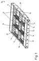
- eine erfindungsgemäße Form in räumlicher Darstellung,
- Fig. 2
- eine Draufsicht auf die Form gemäß Fig. 1,
- Fig. 3
- einen Vertikalschnitt durch die Form gemäß Fig. 1,
- Fig. 4
- ein Formnest der Form gemäß Fig. 1 in teilweiser räumlicher Darstellung,
- Fig. 5 bis Fig. 7
- einen Vertikalschnitt durch die Form gemäß Fig. 1 während unterschiedlicher Phasen des Herstellens von Formlingen aus Beton,
- Fig. 8
- eine Form in räumlicher Darstellung gemäß eines zweiten Ausführungsbeispiels, und
- Fig. 9 bis Fig. 11
- eine Darstellung analog Fig. 5 bis Fig. 7 für das zweite Ausführungsbeispiel gemäß Fig. 8.
- Fig. 1
- a form according to the invention in spatial representation,
- Fig. 2
- a plan view of the mold of FIG. 1,
- Fig. 3
- a vertical section through the mold of FIG. 1,
- Fig. 4
- a mold cavity of the mold according to FIG. 1 in partial spatial representation,
- Fig. 5 to Fig. 7
- 1 shows a vertical section through the mold according to FIG. 1 during different phases of the production of molded articles made of concrete, FIG.
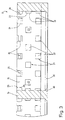
- Fig. 8
- a form in a spatial representation according to a second embodiment, and
- Fig. 9 to Fig. 11
- a representation analogous to FIG. 5 to FIG. 7 for the second exemplary embodiment according to FIG. 8.
Die in den Ausführungsbeispielen schematisch und in wesentlichen Teilen dargestellten Betonformen 10, 11 dienen zur Herstellung von Formlingen aus Beton, z.B. Betonsteinen, Betonhohlkörpern oder dergleichen. Diese weisen mindestens eine durch Abstreifen einer dünnen Betonschicht gebildete Seitenflächen mit aufgerauter Struktur bzw. Oberfläche auf. Aus Gründen der Übersichtlichkeit wurde auf eine Darstellung der Betonsteine bzw. Formlinge verzichtet.The
Die Formlinge bzw. Betonsteine werden in den Betonformen 10, 11 gefertigt, die in der Ausführung gemäß Fig. 8 aus einer einzelnen Kammer bzw. einem einzelnen Formnest 12 besteht und in dem Ausführungsbeispiel gemäß Fig. 1 aus sechs Formnestern 13. Jedes Formnest 12, 13 wird seitlich durch aufrechte Formwände 14, 15 umschlossen. In den gezeigten Ausführungsbeispielen sind die Formwände 14, 15 geschlossen ausgebildet. Zumindest weisen sie in den Bereichen, die zur Formung von Seitenflächen des Formlings dienen, keine Durchbrüche, Öffnungen oder dergleichen auf.The moldings or concrete blocks are manufactured in the
Die Betonform 10, 11 ruht auf einer separaten Unterlage, im vorliegenden Fall auf einem Unterlagsbrett 16. Dieses wiederum liegt üblicherweise auf einem Rütteltisch zum Verdichten des in die Betonformen 10, 11 eingefüllten Betons. Der frische Beton wird von oben durch eine Öffnung 17 in die Betonform 10, 11 bzw. die Formnester 12, 13 eingefüllt, während die Betonform 10, 11 auf dem Unterlagsbrett 16 ruht. Von oben wird dann ein teilweise dargestellter Stempel 18 durch die Öffnung 17 in das oder jedes Formnest 12, 13 eingeführt bzw. abgesenkt, wobei eine Stempelplatte 19 des Stempels 18 gegen die Oberseite des eingefüllten Betons gedrückt wird, zur Formung einer Ober- bzw. Unterseite des Formlings.The
Nach dem Verdichten des Betons wird der Formling entformt. Dies erfolgt durch Anheben der Betonform 10, 11. Während der Aufwärtsbewegung der Betonform 10, 11 wird der Formling auf dem Unterlagsbrett 16 durch den Stempel 18 bzw. die Stempelplatte 19 fixiert. Da die Formnester 12, 13 auch unterseitig eine Öffnung aufweisen, kann die Betonform 10, 11 nach oben vom Formling abgezogen werden, sodass der Formling auf dem Unterlagsbrett 16 ruht und mit diesem abtransportiert werden kann (Fig. 5 - 7 bzw. 9 - 11).After compacting the concrete, the molding is removed from the mold. This is done by lifting the
Die aufgeraute Oberfläche bzw. Seitenfläche des Formlings wird während des Abziehens der Betonform 10, 11 vom Formling herstellt, also während der Aufwärtsbewegung der Betonform 10, 11. Hierzu sind zwei in besonderer Weise ausgebildete Mittel vorgesehen, nämlich einerseits ein Abstreiforgan 20, das an der Außenseite des Formlings entlangbewegt wird und dabei eine Betonschicht vom Formling abstreift. Andererseits dienen hierzu an den Formwänden 14, 15 ausgebildete Organe 21, die zum Inneren des Formnests 12, 13 vorspringen und die in den eingefüllten Beton eintreten. Beim Aufwärtsbewegen der Betonform 10, 11 sorgen auch diese Organe 21 dafür, dass die Betonschicht abgehoben wird. Die Dicke der abgehobenen Betonschicht entspricht dabei etwa der Tiefe der Organe 21. Die besondere Struktur der Seitenfläche des Formlings ergibt sich dadurch, dass der abgestreifte Beton bzw. die abgestreifte Betonschicht entlang der Seitenfläche des Formlings durch das Abstreiforgan 20 bzw. die zum Inneren des Formnests 12, 13 vorspringenden Organe 21 bewegt wird.The roughened surface or side surface of the molding is produced during the removal of the
Das Abstreiforgan 20 ist in den gezeigten Ausführungsbeispielen jeweils am unteren freien Ende der Formwände 14, 15 angeordnet und springt gegenüber diesem zum Inneren des Formnests 14, 15 vor. Das Abstreiforgan 20 bildet damit einen unteren Abschluss der Formwände 15, 16. Das Abstreiforgan 20 kann an einer oder an mehreren Formwänden 14, 15 angeordnet sein. Im Ausführungsbeispiel gemäß Fig. 1 - 7 ist das Abstreiforgan an allen vier aufrechten Formwänden 14, 15 angeordnet. Im zweiten Ausführungsbeispiel gemäß Fig. 8 - 11 ist das Abstreiforgan 20 jeweils gegenüberliegenden Formwänden 14 des Formnests 13 zugeordnet.In the exemplary embodiments shown, the
Die an den Formwänden 14, 15 angeordneten Organe 21, die zum Inneren des Formnests 12, 13 vorspringen, dienen dazu, die abgestreifte Betonschicht beim Abziehen der Betonform 10, 11 an den Formwänden 14, 15 zu halten. Auf diese Weise wird verhindert, dass der abgestreifte Beton auf das Unterlagsbrett 16 oder den Formling fällt.The arranged on the
Bei den gezeigten Ausführungsbeispielen handelt es sich bei den Organen im Wesentlichen um im Querschnitt quadratische bzw. rechteckige Noppen 22. Die Noppen 22 sind mit Abstand zueinander in einer Reihe angeordnet, wobei mehrere Reihen übereinander vorgesehen sind, die parallel zueinander verlaufen. Die Abstände der einzelnen Noppen 22 einer Reihe untereinander sind vorzugsweise etwa gleich groß, wobei die Noppen 22 benachbarter Reihen versetzt zueinander angeordnet sind, sodass an den Formwänden 14, 15 eine gleichmäßige, durch die Noppen 22 gebildete, schachbrettartige Struktur entsteht. Die Noppen 22 sind zudem oberhalb des Abstreiforgans 20 angeordnet. Vorzugsweise stehen die Noppen 22 geringer zum Inneren der Formnester 12, 13 vor als das Abstreiforgan 20. Beispielsweise können die Noppen 22 eine Tiefe von 5 mm aufweisen und das Abstreiforgan 20 eine Tiefe von 6 mm. Weiterhin ist vorgesehen, dass die Noppen 22 zweier benachbarter horizontaler Reihen sich in vertikaler Ziehrichtung nicht überlappen, sondern dass ein "freier Bereich" gebildet ist, der beispielsweise gemäß Fig. 3 etwa 8 mm betragen kann.In the exemplary embodiments shown, the bodies are essentially
Die quaderförmigen Noppen 22 weisen im gezeigten Ausführungsbeispiel eine plane, zur Innenseite des Formnests 12, 13 gerichtete Stimfläche auf, die parallel zu den Formwänden 14, 15 verläuft. Die Stirnflächen 23 der Noppen 22 befinden sich alle in der gleichen Ebene, wobei diese Ebene gegenüber der Ebene der Vorderkante des Abstreiforgans 20 zurückgesetzt ist. Die Stirnflächen 23 der Noppen 22 können optional angeraut oder beispielsweise gerillt ausgebildet sein, um die optische Qualität der aufgerauten Seitenflächen des Betonsteins zu verbessern. Die Grundrissabmessungen der Stirnfläche 23 können beispielsweise 16 x 16 mm betragen. Die Gestalt der Noppen 22 kann natürlich variieren, insbesondere um unterschiedliche Effekte zu erzeugen. Denkbar sind beispielsweise stegartige Gebilde oder vorspringende Organe mit einer dreieckigen Sichtseite, deren Spitze in Abziehrichtung der Betonform 10, 11 gerichtet ist.In the exemplary embodiment shown, the
Eine Besonderheit besteht darin, dass einzelne Organe 24 weiter zum inneren der Formnester 12, 13 vorspringen als die vorstehend beschriebenen Organe 21 bzw. Noppen 22. Diese Organe 24 dienen dazu, den Stempel 18 über die Stempelplatte 19 beim Absenken in die Formnester 12, 13 zu zentrieren. Zu diesem Zweck springen die Organe 24 zur Zentrierung des Stempels 18 derart zum Inneren des Formnests 12, 13 vor, dass die Öffnung 17 an der Oberseite der Betonform 10, 11 durch die Organe 24 verkleinert wird und in etwa den Abmessungen der Stempelplatte 19 entspricht. Die Organe 24 dienen demnach dazu, die lichte Weite der Öffnung 17 an die Grundrissabmessungen der Stempelplatte 19 anzupassen. Im gezeigten Ausführungsbeispiel beträgt die Tiefe etwa 22 mm.A special feature is that
Da nicht an allen Formwänden 14, 15 der Betonform 10, 11 Organe 21, 24 angeordnet sein müssen, kann die Öffnung 17 auch nur an einer oder mehreren Formwänden 14, 15 durch die Organe 24 begrenzt sein, wohingegen andere Formwände 14, 15. ohne Vorsprünge ausgebildet sind. Es kann auch sein, dass einzelne Formwände keine Organe 21 im unteren Bereich der Formwand 14, 15 aufweisen, jedoch mit einem zentrierenden Organ 24 im Bereich der Öffnung 17 versehen sind.Since not all the
Die zentrierend wirkenden Organe 24 sind in den gezeigten Ausführungsbeispielen am oberen freien Ende der Formwände 14, 15 angeordnet. Die Organe 24 sind zudem im Querschnitt mit einer oberseitigen und unterseitigen Fase 25 versehen. Die Fase 25 erleichtert das Einführen der Stempelplatte 19 in die Öffnung 17 und korrigiert geringfügige Fehlstellungen der Stempelplatte 19. Sofern die Stempelplatte 19 unterhalb des Niveaus der Organe 24 abgesenkt wird, unterstützt die unterseitige Fase 25 in gleicher Weise das Herausziehen des Stempels 18 aus dem Formnest 12, 13.The centering
Die Lage der zentrierenden Organe 24 am oberen freien Rand der Formwände 14, 15 ist nicht zwingend. Selbstverständlich können sich die Formwände 14, 15 auch weiter nach oben erstrecken. Die zentrierenden Organe 24 sollten aber im Bezug auf einen maximalen Füllstand der Form 10, 11 derart angeordnet sein, dass die auf der Oberseite der Formlinge bzw. des eingefüllten Betons aufliegende Stempelplatte 19 beim Absenken in das Formnest 12, 13 vorher in Kontakt mit den zentrierenden Organen 24 kommt.The position of the centering
Unter Bezugnahme auf Fig. 5 - 7 erfolgt das Herstellen der Formlinge wie folgt: Die Betonform 10, 11 wird auf dem Unterlagsbrett 16 abgesetzt, sodass die Formnester 12, 13 unterseitig verschlossen sind. Der Stempel 18 mit Stempelplatte 19 befindet sich in einer angehobenen Stellung außerhalb des Formnests 12, 13, sodass die obere Öffnung 17 frei ist zum Einfüllen von Beton (Fig. 5). Nach dem Einfüllen des Betons wird der Stempel 18 durch die Öffnung 17 in die Formnester 12, 13 herabgesenkt, wobei er in Kontakt mit den zentrierenden Organen 24 gelangt und dabei in exakter Relativposition über dem Formling ausgerichtet wird (Fig. 6). Danach wird die Betonform 10, 11 nach oben von den Formlingen abgezogen. Die Oberseite des Formlings liegt dabei an der Unterseite der Stempelplatte 19 an, sodass die Formlinge nicht zusammen mit der Betonform 10, 11 angehoben werden können. Bei diesem Abziehen der Betonform 10, 11 von den Formlingen wird an den Seitenflächen des Formlings, die den mit Organen 21, 24 versehenen Formwänden 14, 15 zugewandt sind, eine Betonschicht abgehoben bzw. abgeschält. Die Dicke der Betonschicht entspricht dabei etwa dem horizontalen Maß von der Innenseite der Formwände 14, 15 bis zur Vorderkante des Abstreiforgans 20(Fig. 7).With reference to FIGS. 5-7, the moldings are manufactured as follows: The
Die Betonform des zweiten Ausführungsbeispiels gemäß Fig. 8 - 11 zeichnet sich zum einen durch einen polygonalen Grundriss aus. Zudem wird in dieser Betonform 11 nur ein einzelner Formling hergestellt. Der Formling weist an zwei gegenüberliegenden Seitenflächen eine aufgeraute Außenseite auf, sodass auch nur die entsprechend zugewandten Formwände 14 die Organe 21, 24 und das Abstreiforgan 20 aufweisen. Ein weiterer Unterschied besteht zudem darin, dass das zentrierende Organ 24 sich durchgehend entlang der Formwände 14 erstreckt, wohingegen die Formwände 15 weder Organe 21 bzw. Noppen 22 noch ein zentrierendes Organ 24 aufweisen. Da die Formlinge, die in dieser Betonform 11 hergestellt werden sollen nur eine geringe Höhe aufweisen, erstrecken sich die Organe 24 auch über eine entsprechend größere Höhe entlang der Formwände 14, nämlich vom oberen freien Rand derselben bis kurz unter den maximalen Füllstand der Betonform 11, also bis kurz unterhalb einer unteren Endposition der Stempelplatte 19.The concrete form of the second embodiment shown in FIG. 8 - 11 is characterized on the one hand by a polygonal floor plan. In addition, in this
- 1010
- Betonformconcrete form
- 1111
- Betonformconcrete form
- 1212
- Formnestcavity
- 1313
- Formnestcavity
- 1414
- Formwandmold wall
- 1515
- Formwandmold wall
- 1616
- Unterlagsbrettsupport board
- 1717
- Öffnungopening
- 1818
- Stempelstamp
- 1919
- Stempelplattestamp plate
- 2020
- Abstreiforganwringing
- 2121
- Organorgan
- 2222
- Noppenburl
- 2323
- Stirnflächeface
- 2424
- Organorgan
- 2525
- Fasechamfer
Claims (17)
Applications Claiming Priority (1)
| Application Number | Priority Date | Filing Date | Title |
|---|---|---|---|
| DE200510012199 DE102005012199A1 (en) | 2005-03-15 | 2005-03-15 | Device for the production of molded articles from concrete |
Publications (2)
| Publication Number | Publication Date |
|---|---|
| EP1702736A2 true EP1702736A2 (en) | 2006-09-20 |
| EP1702736A3 EP1702736A3 (en) | 2007-05-30 |
Family
ID=36579640
Family Applications (1)
| Application Number | Title | Priority Date | Filing Date |
|---|---|---|---|
| EP06005057A Withdrawn EP1702736A3 (en) | 2005-03-15 | 2006-03-13 | Apparatus for making concrete articles |
Country Status (2)
| Country | Link |
|---|---|
| EP (1) | EP1702736A3 (en) |
| DE (1) | DE102005012199A1 (en) |
Citations (2)
| Publication number | Priority date | Publication date | Assignee | Title |
|---|---|---|---|---|
| US5078940A (en) | 1990-05-31 | 1992-01-07 | Sayles Jerome D | Method for forming an irregular surface block |
| DE10247259A1 (en) | 2002-10-10 | 2004-04-22 | Sf-Kooperation Gmbh Beton-Konzepte | The appliance for producing concrete blanks incorporates scraper . at least one outer surface with scraper for roughening blank |
Family Cites Families (7)
| Publication number | Priority date | Publication date | Assignee | Title |
|---|---|---|---|---|
| US3940229A (en) * | 1974-02-22 | 1976-02-24 | Columbia Machine, Inc. | Apparatus for manufacturing rough faced bricks |
| US5217630A (en) * | 1990-05-31 | 1993-06-08 | Sayles Jerome D | Apparatus for forming an irregular surface block |
| DE4447062A1 (en) * | 1994-12-29 | 1996-07-04 | Rampf Formen Gmbh | Multi-chamber mold for the mechanical production of shaped bodies made of concrete |
| US5879603A (en) * | 1996-11-08 | 1999-03-09 | Anchor Wall Systems, Inc. | Process for producing masonry block with roughened surface |
| DE10110651A1 (en) * | 2001-03-06 | 2002-09-12 | Kobra Formen Gmbh | Mold for the production of moldings |
| CA2462889C (en) * | 2001-10-09 | 2010-05-25 | Dean Jurik | Textured masonry block mold and method |
| US7021919B2 (en) * | 2002-12-02 | 2006-04-04 | Tom Griffith | Apparatus for forming concrete blocks or stones with a rough surface |
-
2005
- 2005-03-15 DE DE200510012199 patent/DE102005012199A1/en not_active Withdrawn
-
2006
- 2006-03-13 EP EP06005057A patent/EP1702736A3/en not_active Withdrawn
Patent Citations (2)
| Publication number | Priority date | Publication date | Assignee | Title |
|---|---|---|---|---|
| US5078940A (en) | 1990-05-31 | 1992-01-07 | Sayles Jerome D | Method for forming an irregular surface block |
| DE10247259A1 (en) | 2002-10-10 | 2004-04-22 | Sf-Kooperation Gmbh Beton-Konzepte | The appliance for producing concrete blanks incorporates scraper . at least one outer surface with scraper for roughening blank |
Also Published As
| Publication number | Publication date |
|---|---|
| DE102005012199A1 (en) | 2006-09-21 |
| EP1702736A3 (en) | 2007-05-30 |
Similar Documents
| Publication | Publication Date | Title |
|---|---|---|
| DE4402281A1 (en) | Method of manufacturing Concrete paving blocks | |
| DE4333942A1 (en) | Construction set of shaped concrete blocks and device for producing the same | |
| DE4200602A1 (en) | METHOD AND DEVICE FOR PRODUCING HOLE STONES | |
| EP1568455B1 (en) | Process and apparatus for producing concrete paving stones and paving stone | |
| WO2002051603A2 (en) | Method for producing purpose-made blocks, a device therefor and a row of purpose-made blocks | |
| DE3740682C2 (en) | ||
| WO1988007920A1 (en) | Device for manufacture of an artificial stone | |
| EP1702736A2 (en) | Apparatus for making concrete articles | |
| EP1551606B1 (en) | Device for the production of formed concrete pieces having a rough surface and formed concrete piece | |
| EP0316653A2 (en) | Concrete palisade and process and apparatus for its manufacture | |
| AT524345B1 (en) | Semi-brick and method of producing a semi-brick | |
| AT500460B1 (en) | DEVICE FOR PRODUCING A CAVITY UNIT FROM A HYDRAULICALLY HARDENING, HUMIDITY COMPONENT | |
| WO2005030455A1 (en) | Method for the production of molded concrete pieces | |
| DE19704771C2 (en) | Method and device for inserting a reinforcement mat into a mold | |
| DE2521602A1 (en) | Ceramic tiles with raised decorative pattern - obtd. by using network of grooves on lower punch in tile press | |
| DE2551476C3 (en) | Process for the standing casting of building boards, e.g. made of plaster | |
| EP0778112B1 (en) | Process for making wall elements | |
| DE19747770A1 (en) | Method and device for the production of concrete blocks, and concrete blocks produced therefrom or therewith | |
| DE441159C (en) | Forming device for cement and concrete blocks | |
| DE2703677A1 (en) | Mould box for making plaster panels - has partition linings imparting surface pattern to moulded material, and ejected with panel | |
| DE6610213U (en) | FORM FOR THE MANUFACTURING OF STRUCTURES, IN PARTICULAR PANELS MADE OF CONCRETE OR SIMILAR MATERIAL. | |
| DE4243333C2 (en) | Form and method of manufacturing concrete bodies | |
| EP0609825A1 (en) | Process and apparatus for pressing in particular an article of largely quadratic form | |
| DE10006711A1 (en) | Method and appliance for producing concrete blocks involve mold, base part, cavity, wiper plate, shaker sieve, and casing | |
| DE10004254A1 (en) | Curved concrete molding shell is composed of a number of shell blocks with curved molding surfaces assembled together to give the required shape and dimensions to the cast concrete |
Legal Events
| Date | Code | Title | Description |
|---|---|---|---|
| PUAI | Public reference made under article 153(3) epc to a published international application that has entered the european phase |
Free format text: ORIGINAL CODE: 0009012 |
|
| AK | Designated contracting states |
Kind code of ref document: A2 Designated state(s): AT BE BG CH CY CZ DE DK EE ES FI FR GB GR HU IE IS IT LI LT LU LV MC NL PL PT RO SE SI SK TR |
|
| AX | Request for extension of the european patent |
Extension state: AL BA HR MK YU |
|
| PUAL | Search report despatched |
Free format text: ORIGINAL CODE: 0009013 |
|
| AK | Designated contracting states |
Kind code of ref document: A3 Designated state(s): AT BE BG CH CY CZ DE DK EE ES FI FR GB GR HU IE IS IT LI LT LU LV MC NL PL PT RO SE SI SK TR |
|
| AX | Request for extension of the european patent |
Extension state: AL BA HR MK YU |
|
| AKX | Designation fees paid | ||
| STAA | Information on the status of an ep patent application or granted ep patent |
Free format text: STATUS: THE APPLICATION IS DEEMED TO BE WITHDRAWN |
|
| 18D | Application deemed to be withdrawn |
Effective date: 20071101 |
|
| REG | Reference to a national code |
Ref country code: DE Ref legal event code: 8566 |