EP1697140B1 - Striping and clipping correction - Google Patents
Striping and clipping correction Download PDFInfo
- Publication number
- EP1697140B1 EP1697140B1 EP04814917A EP04814917A EP1697140B1 EP 1697140 B1 EP1697140 B1 EP 1697140B1 EP 04814917 A EP04814917 A EP 04814917A EP 04814917 A EP04814917 A EP 04814917A EP 1697140 B1 EP1697140 B1 EP 1697140B1
- Authority
- EP
- European Patent Office
- Prior art keywords
- stripe
- printing
- moving object
- stripes
- Prior art date
- Legal status (The legal status is an assumption and is not a legal conclusion. Google has not performed a legal analysis and makes no representation as to the accuracy of the status listed.)
- Active
Links
Images


Classifications
-
- G—PHYSICS
- G06—COMPUTING; CALCULATING OR COUNTING
- G06K—GRAPHICAL DATA READING; PRESENTATION OF DATA; RECORD CARRIERS; HANDLING RECORD CARRIERS
- G06K1/00—Methods or arrangements for marking the record carrier in digital fashion
- G06K1/12—Methods or arrangements for marking the record carrier in digital fashion otherwise than by punching
- G06K1/126—Methods or arrangements for marking the record carrier in digital fashion otherwise than by punching by photographic or thermographic registration
-
- B—PERFORMING OPERATIONS; TRANSPORTING
- B41—PRINTING; LINING MACHINES; TYPEWRITERS; STAMPS
- B41J—TYPEWRITERS; SELECTIVE PRINTING MECHANISMS, i.e. MECHANISMS PRINTING OTHERWISE THAN FROM A FORME; CORRECTION OF TYPOGRAPHICAL ERRORS
- B41J2/00—Typewriters or selective printing mechanisms characterised by the printing or marking process for which they are designed
- B41J2/435—Typewriters or selective printing mechanisms characterised by the printing or marking process for which they are designed characterised by selective application of radiation to a printing material or impression-transfer material
- B41J2/47—Typewriters or selective printing mechanisms characterised by the printing or marking process for which they are designed characterised by selective application of radiation to a printing material or impression-transfer material using the combination of scanning and modulation of light
-
- B—PERFORMING OPERATIONS; TRANSPORTING
- B41—PRINTING; LINING MACHINES; TYPEWRITERS; STAMPS
- B41J—TYPEWRITERS; SELECTIVE PRINTING MECHANISMS, i.e. MECHANISMS PRINTING OTHERWISE THAN FROM A FORME; CORRECTION OF TYPOGRAPHICAL ERRORS
- B41J3/00—Typewriters or selective printing or marking mechanisms characterised by the purpose for which they are constructed
- B41J3/407—Typewriters or selective printing or marking mechanisms characterised by the purpose for which they are constructed for marking on special material
- B41J3/4073—Printing on three-dimensional objects not being in sheet or web form, e.g. spherical or cubic objects
-
- B—PERFORMING OPERATIONS; TRANSPORTING
- B65—CONVEYING; PACKING; STORING; HANDLING THIN OR FILAMENTARY MATERIAL
- B65B—MACHINES, APPARATUS OR DEVICES FOR, OR METHODS OF, PACKAGING ARTICLES OR MATERIALS; UNPACKING
- B65B61/00—Auxiliary devices, not otherwise provided for, for operating on sheets, blanks, webs, binding material, containers or packages
- B65B61/26—Auxiliary devices, not otherwise provided for, for operating on sheets, blanks, webs, binding material, containers or packages for marking or coding completed packages
Landscapes
- Engineering & Computer Science (AREA)
- Physics & Mathematics (AREA)
- General Physics & Mathematics (AREA)
- Theoretical Computer Science (AREA)
- Manufacturing & Machinery (AREA)
- Mechanical Engineering (AREA)
- Electronic Switches (AREA)
- Laser Beam Printer (AREA)
- Printers Characterized By Their Purpose (AREA)
- Control Of Exposure In Printing And Copying (AREA)
Description
- Modem production practices often involve printing an identification code on commercial products. These codes are easily observed on common products such as soda cans, cosmetics, pet food containers, etc. Some govemment regulatory agencies, such as the Food and Drug Administration, may require certain products to have such codes.
- These codes often include information that is unique to the time and place at which the product is manufactured. For instance, many codes communicate a batch number associated with a product. Many codes go further and indicate the actual time and date of manufacture. Because some codes relate to unique manufacturing parameters (e.g., time and date), some codes cannot be pre-printed on a label for a product. Hence, a code is often printed on the label after the product is manufactured. Current code printing technology includes the use of ink jets, which spray ink onto the label.
US 6,061,081 describes a laser marking device according to the preamble ofclaim 1 used to form a mark on the surface of a moving object, in which the scanning speed is set so that a marking operation is started when a reference point reaches the irradiation start point, and is ended when the reference point reaches the irradiation end point. - According to the invention, there is provided a system comprising: a laser source to print an image on a moving object; an input module to receive information identifying a velocity of the moving object and an initial position of the moving object relative to the laser source; and a processor to perform operations including: separating an image to be printed on the moving object into a plurality of stripes that collectively represent the image to be printed: based on one or more of (a) the velocity of the moving object, (b) the initial position of the moving object relative to the laser source, and (c) a parameter of a stripe to be printed, determining at least one of a time to print the stripe and a location on the moving object at which to print the stripe: and controlling the laser source to print the stripe on the moving object according to at least one of the time and location values; characterised in that the processor is further arranged to perform the operations of: calculating a clipping correction value in the form of either an interstripe distance, to ensure printing of the entire image is completed, or an interstripe time delay, to ensure stripes of the image are printed at proper locations; and using the clipping correction value to control printing by the laser source on the moving object.
According to the invention, there is also provided a method comprising: organizing an image to be printed into a plurality of stripes that collectively represent the image; based on one or more of (a) a velocity of a moving object, (b) an initial position of the moving object relative to a laser beam, and (c) a parameter of a stripe to be printed, determining at least one of a time to print the stripe and a location on the moving object at which to print the stripe; and printing the stripe with the laser beam on the moving object based on at least the determined time to print and the location; and characterised in that the method further comprises: calculating a clipping correction value in the form of either an interstripe distance, to ensure all stripes of the image are printed, or an interstripe time delay, to ensure stripes of the image are printed at desired stripe locations; and using the clipping correction value to control printing by the laser beam on the moving object.
Preferable features are defined in the dependent claims. - The present application relates to a printing system that uses a laser to print an image (e.g., code/sequence of symbols and characters) on a moving product. Specifically, the application relates to software or firmware in the printing system that organizes an image to a sequence of "stripes" and prints the stripes on the moving product. The software uses the stripes to provide an efficient print order of characters and symbols, which may speed up printing. The software may optimize use of the laser's exposure window (aperture) and minimize an amount of laser deflection motion between marking operations.
- image clipping occurs when a full image cannot be printed because a product is moving too fast or too slow, and the aperture limits the laser beam path. The software may select in real time an optimum position on the product to print one or more symbols. The software may use the stripes to provide real-time "leading edge" image clipping correction to print stripes on products moving at high speeds. The software may use the stripes to provide real-time "trailing edge" clipping correction to print stripes on products moving at slow speeds or to print long codes. The software may also provide real-time clipping correction updates. Thus, the software may ensure that an entire code will be printed on the product and attempts to maintain legibility of the printed code.
- Clipping correction enables the printing system to successfully print desired images on slow products, fast products, and products with changing velocities without controlling the product's speed.
- Striping and clipping correction allows the printing system to print more complex images (codes) and longer images on products, such as images that are longer than the aperture. Clipping correction may enable printing very long sequences of symbols.
- Clipping correction may enable a laser to be mostly centered in an aperture during printing. Optical power loss may be at a minimum in the center of the aperture. Remaining mostly centered may lead to more consistent laser marking.
- The software may be CIJ (character ink jet) compatible.
- An aspect of the application relates to a system comprising a laser source, an input module, and a processor. The laser source prints an image on a moving object. The input module receives information identifying a velocity of the moving object and a location of the moving object. The processor performs operations including: separating an image to be printed on the moving object into a plurality of stripes that collectively represent the image to be printed; based on one or more of (a) the velocity of the moving object, (b) the location of the moving object, and (c) a parameter of a stripe to be printed, determining at least one of a time to print the stripe and a location on the moving object at which to print the stripe; and controlling the laser source to print the stripe on the moving object according to the time and location values.
- Another aspect relates to a system comprising: a first module to organize an image to a plurality of stripes; a second module to receive the stripes, a trigger input and a velocity input to determine at least one of (a) locations on a moving object to print the stripes, and (b) a time at which to print at least one stripe on the moving object; and a laser source to print the stripes on the moving object.
- Another aspect relates to a method comprising: organizing an image to be printed into a plurality of stripes that collectively represent the image; based on one or more of (a) a velocity of a moving object, (b) a location of the moving object, and (c) a parameter of a stripe to be printed, determining at least one of a time to print the stripe and a location on the moving object at which to print the stripe; and printing the stripe with a laser beam on the moving object based on the determined time to print and the location.
- Details one or more implementations are set forth in the accompanying drawings and the description below. Other features and advantages may be apparent from the description, drawings and/or claims.
-
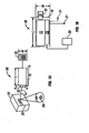
Fig. 1A is a side view of a printing system. -
Fig. 1B is a cross-section of the printing system ofFig. 1A looking down on to the printing system. -
Fig. 2 illustrates the printing system ofFig. 1A forming a print zone upon a product. -
Fig. 3A is a side view of a printing system used in conjunction with a product line which temporarily stops a product in front of the printing system. -
Fig. 3B is a side view of a printing system used in conjunction with a product line which continuously moves a product in front of the printing system. -
Fig. 3C is a top view of the printing system ofFig. 3B used in conjunction with a product line which continuously moves the product in front of the printing system. -
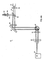
Fig. 4A illustrates an optical assembly for use in the printing system ofFig. 1A . -
Fig. 4B is a side view of a plurality of mirrors ofFig. 4A configured to steer a printing beam produced by the printing system from one location to another on a product where a code is to be formed. -
Fig. 4C illustrates the relationship between an optics assembly and a housing of the printing system ofFig. 4A . -
Fig. 4D illustrates the non-linear nature of a lens used in the optics assembly ofFig. 4A . -
Fig. 4E illustrates a bearing ofFig. 4B which allows a printing beam exit member of the printing system to be rotated relative to a housing of the printing system. -
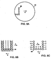
Fig. 5A is a side view of a printing beam being incident on a material at a location where a spot is to be formed on the material. -
Fig. 5B is a perspective view of a printing beam being incident on a material at a location where a spot is to be formed on the material. -
Fig. 5C is a side view of a material after the printing beam has formed a spot in the material. -
Fig. 5D is a perspective view of a material after the printing beam has formed a spot in the material. -
Figs. 6A-6D illustrate formation of pixels having different sizes. -
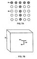
Fig. 7A illustrates an array of possible pixels which are selected to form a symbol within the array. -
Fig. 7B illustrates the symbol ofFig. 7A printed on a product. -
Fig. 8A illustrates an aperture which limits the area within which the printing system is able to print. -
Fig. 8B illustrates a symbol to be printed on a product continuously moving in front of the printing system. -
Fig. 8C illustrates a symbol to be printed on a product continuously moving in front of the printing system. -
Fig. 9A illustrates conversion of a code to a corrected code. -
Fig. 9B illustrates a code being organized to a corrected code. -
Fig. 9C illustrates the corrected code ofFig. 9C . -
Fig. 9D illustrates the code formed on the product after the corrected code ofFig. 9C is printed on the product while the product is continuously moved past the printing system. -
Fig. 10A illustrates conversion of a pixel to a corrected pixel. -
Fig. 10B illustrates the corrected pixel ofFig. 10A . -
Fig. 10C illustrates the pixel formed on the product after the corrected pixel ofFig. 10B is printed on the product while the product is continuously moved past the printing system. -
Fig. 10D illustrates a spot formed on a stationary product. -
Fig. 10E illustrates the spot ofFig. 10D formed on a product as the product is moving. -
Fig. 11A illustrates a relationship between the product, the print trigger, the printing system ofFig. 1A and the print area. -
Fig. 11B illustrates the leading edge of a print area. -
Fig. 12 illustrates a plurality of software modules in the electronics ofFig. 1B . -
Figs. 13A-13C illustrate examples of stripes created by the image processing module ofFig. 12 . -
Fig. 14A illustrates an example of an desired image to be printed. -
Fig. 14B illustrates an example of a clipped printed image affected by "leading edge" clipping. -
Figs. 14C-14E illustrate examples of clipping correction. -
Fig. 15A illustrates an example of leading edge clipping. -
Fig. 15B illustrates a desired code "1 2 3 4" to be printed in a desired print zone according to the distance scale inFig. 15A . -
Fig. 15C illustrates an example of leading edge clipping correction. -
Fig. 15D illustrates the corrected code "1 2 3 4" printed in the desired print zone according to the distance scale inFig. 15C . -
Fig. 15E illustrates clipping correction configured to enable a laser to be mostly centered in an aperture while printing four stripes "1 2 3 4." -
Fig. 16A illustrates an example of trailing edge clipping. -
Fig. 16B illustrates a desired code "1 2 3 4" to be printed in the desired print zone according to the distance scale inFig. 16A . -
Fig. 16C illustrates an example of trailing edge clipping correction and adding delays. -
Fig. 17 illustrates a method of using the software modules ofFig. 12 . -
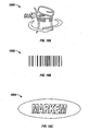
Figs. 18A-18C illustrate examples of a sign, a bar code and a company logo, respectively, which may be marked with the software modules and electronics inFig. 12 . - The application relates to a printing system for printing a code on a product positioned adjacent to the printing system. In particular, the application relates to an optics assembly, such as low angle optics and reversed optics, in the printing system. The printing system includes a laser for producing a printing beam. The optics assembly steers the printing beam from one location to another location on the product. The printing system includes electronics for adjusting the time that the printing beam dwells at each location. This "dwell time" is adjusted such that the printing beam causes a spot to be formed at each location.
- The locations can be arranged such that the spots form a pixel on the product. The pixels in turn can be arranged to form the symbols of a code. The symbols of the code can be the symbols which are available in word processing programs such as alphanumeric symbols and any other symbols used to identify a product batch, date, etc. The code can be readable text such as product names or identifiers. The code need not be alphanumeric and can include symbols which are not produced by typical word processing programs. For instance, the code can be a bar code.
- The products for use with the printing system can be products to be sold retail or packaging of retail products. Further, the products can be products which are sold to other businesses. Examples of products include pharmaceuticals, pharmaceutical packaging, food packaging, cosmetics, food such as eggs, dairy products, ice cream, computer components, automotive components, medical devices, detergents and beverages such as soft drinks and wines.
- The code can be formed in multiple locations on a product. For instance, plastic medicine bottles can have one code printed directly on the plastic bottle and another code formed on the label attached to the plastic bottle.
- As described above, the code is constructed from a plurality of spots. The spot is formed on the product by altering an optical characteristic of the material at the location where the printing beam is incident on the product. The printing beam can alter a variety of optical characteristics of a product. For instance, the printing beam can cause one or more layers of material to be ablated so the underlying layers are visible. Since upper layers of a material often have an ink layer on paper, removal of the ink layer leaves a spot where the paper is visible against the surrounding ink layer. The refractive characteristics of a material can also be altered. For instance, the printing beam can be used to print a code on a plastic such as a soft drink bottle. The printing beam alters the refractive characteristics of the plastic. The code is easily visible since the eye can pick up the sections having contrasting refractive properties. In addition, the printing beam can etch certain materials.
- Since the printing system employs a laser in order to print on the product, there is no need for consumables such as inks and solvents. Accordingly, the printing system can reduce the costs and complexity associated with printing a code on a product
- Traditional printing systems which employ a laser for printing a code on a product typically employ high powered lasers which often require liquid cooling and large amounts of space. However, in the printing system described below, the time that a laser dwells at each location can be increased to compensate for reductions in the power of the laser. As a result, a low powered laser can be employed in the printing system. For instance, in one embodiment, the laser is a CO2 air cooled laser. In some instances the laser is at most a 25 Watt laser, in other instances the laser is at most a 20 Watt laser, in other instances the laser is at most a 15 Watt laser and in still other instances the laser is at most a 13 Watt laser.
- Because the laser can be a low power laser, the laser, optics assembly and associated electronics can be mounted in a housing having a size on the order of an ink jet printer. As a result, the ability to adjust the dwell time means that the printing system according to the present overcomes the size and space challenges associated with traditional printing systems which employ a laser. Hence, the printing system described below is an improved substitute for ink jets used to print codes on products.
- The printing system may be suitable for printing on products that are moving such as the products in a production line. Because these products are moving relative to the system, there is a limited amount of time available for printing on each product. The printing system includes electronics for varying the amount of time to print the code on the product. For instance, the printing system includes electronics for changing the density of pixels that define the code. Codes having a reduced pixel density can be printed more quickly than codes with an increased pixel density. Further, the printing system includes electronics for changing the size of the pixels that define the code. Smaller pixels need less printing time. In addition, the dwell time of the printing system can be changed as noted above. The ability to change the time needed to print a code allows the printing system to be used in conjunction with more production lines.
-
Figs. 1A and 1B illustrate aprinting system 10 for printing on aproduct 22 positioned adjacent to theprinting system 10.Fig. 1A is a side view of theprinting system 10, whileFig. 1B is a cross sectional top view of theprinting system 10. Theprinting system 10 includes alaser 12 for producing aprinting beam 14. Anylaser 12 can be used in the printing system. Since the dwell time can be increased in order to compensate for the reduced laser power, a low powered laser can be employed in the printing system. For instance, thelaser 12 can be a CO2 air-cooled laser. In some instances, the laser may be a 25-Watt laser, a 20-Watt laser, a 15-Watt laser or a 13-Watt laser. - The
printing beam 14 from the laser/energy source 12 passes through anoptics assembly 18 and is incident on amaterial 20, such as the material used in product packaging. As will be described in more detail below, the time that thebeam 14 is incident on thematerial 20 can be adjusted such that thebeam 14 causes a spot to be formed on thematerial 20. - The
optics assembly 18 includes components for altering the direction of theprinting beam 14. These components can be controlled to steer theprinting beam 14 from one location to another location so as to create a spot at each of the locations. As will be described in more detail below, the spots can be arranged to form one ormore pixels 88 on thematerial 20. In addition, thesepixels 88 can be arranged to form one or more symbols on thematerial 20. These symbols can be an alphanumeric code printed on aproduct 22 or on the label of aproduct 22. - The
printing system 10 also includeselectronics 26 in communication with the laser/energy source 12 and theoptics assembly 18. Theelectronics 26 can include one or more processors for providing the functionality to theprinting system 10. Suitable processors include, but are not limited to, microprocessors, digital signal processors (DSP), integrated circuits, application specific integrated circuits (ASICs), logic gate arrays and switching arrays. Theelectronics 26 can also include one or more memories for storing instructions to be carried out by the one or more processors and/or for storing data developed during operation of theprinting system 10. Suitable memories include, but are not limited to, RAM and electronic read-only memories (e.g., ROM, EPROM, or EEPROM). - The
electronics 26 control the operation of thelaser 12 and theoptics assembly 18. For instance, theelectronics 26 can control theoptics assembly 18 to adjust the direction of theprinting beam 14, the length of time that theprinting beam 14 dwells at a location on thematerial 20 where a spot is to be formed, the speed that theprinting beam 14 moves between each location where the beam dwells, the size ofpixels 88 used to create visually recognizable symbols, the selection of symbols created, etc. - The
electronics 26 can optionally be in communication with auser interface 30. Theuser interface 30 can be remote from thehousing 16, attached to thehousing 16 and/or detachable from thehousing 16. Theuser interface 30 may be a handheld device. Asuitable user interface 30 can include an alphanumeric keyboard and a display. Theuser interface 30 can be used to program theelectronics 26 and/or set printing parameters. For instance, theuser interface 30 can be used to manually control the time that theprinting beam 14 dwells at a single location on thematerial 20, the size of thepixels 88 used to form a visually observable symbol, the type and/sequence of symbol which are formed, etc. Theuser interface 30 can also be used to manually activate theprinting system 10. For instance, theuser interface 30 can include a print key which causes theprinting system 10 to print on thematerial 20. - The
electronics 26 can also be in communication with one ormore sensors 31. Thesesensors 31 can provide theelectronics 26 with information about the products on which theprinting system 10 is to print. For instance, thesensors 31 can indicate the location of aproduct 22 relative to theprinting system 10, the direction that aproduct 22 is moving, when a movingproduct 22 has been stopped, and when aproduct 22 is in the correct position to be printed upon. Suitable sensors 31 (described below) may include, but are not limited to, a speed sensor for detecting the speed and/or direction that aproduct 22 is moving and a location sensor for indicating when aproduct 22 is positioned in front of thesensor 31. - The
printing system 10 includes a printingbeam exit member 32 through which theprinting beam 14 exits thehousing 16. The printingbeam exit member 32 can be as simple as an opening in thehousing 16 or an immobile window mounted in thehousing 16. In another embodiment, the printingbeam exit member 32 can be moved relative to thehousing 16 as illustrated by the arrow labeled A. In this embodiment, theprinting beam 14 can be manually aimed toward a particular position on thematerial 20 by manipulating the printingbeam exit member 32. - Because the laser can be a low power laser, the
housing 16 can also be compact. For instance, thehousing 16 can have a volume of less than 1200 cubic inches. In some instances, thehousing 16 has a volume less than 900 cubic inches In other instances, thehousing 16 has a volume less than 1200 inches. In one embodiment, thehousing 16 has a length, L, less than 25 inches, a width, W, less than 10 inches and a height, H, less than 5 inches. In another embodiment, thehousing 16 has a length, L, less than 23.5 inches, a width, W, less than 7.5 inches and a height, H, less than 4 inches. For purposes of these dimensions, thehousing 16 may include the printbeam exit member 32. - The small size is also associated with a low weight. For instances, in one embodiment, the
housing 16 and the enclosed components weighs less than 30 pounds. In some instances, thehousing 16 and the enclosed components weigh less than 25 pounds and in other instances, thehousing 16 and the enclosed components weigh less than 22 pounds. This weight does not include the weight of components which are remote from thehousing 16. For instance, this weight does not includeuser interfaces 30 which are not integral to thehousing 16. In addition, this weight does not include the weight of any sensors with which theprinting system 10 is in communication but which are not integral with thehousing 16. -
Fig. 2 illustrates an example of theprinting system 10 forming aprint zone 34 upon aproduct 22. Theprinting system 10 can include components for defining theprint zone 34 on thematerial 20. For instance, theprinting system 10 can project a rectangle onto the material 20 as illustrated inFig. 2 . Theprinting system 10 forms the symbol of the code within theprint zone 34. - During operation of the
printing system 10, theprint zone 34 may be printed automatically or be controlled by an operator. The operator may adjust thebeam outlet member 32 so that theprint zone 34 is formed at a desired location on thematerial 20. Theuser interface 30 is then used to activate print within theprint zone 34. As a result, the operator of theprinting system 10 can select where theprinting system 10 prints a code on thematerial 20 by ensuring that theprint zone 34 appears in the desired print location. Suitable print zone marks may include, but are not limited to, marks at the four corners of aprint zone 34, a mark positioned in the center of theprint zone 34, and a dashed line around theprint zone 34. - In one embodiment of the
printing system 10, theelectronics 26 control the size and geometry of theprint zone 34. As a result, theelectronics 26 can match the size and shape of the symbols to be printed on thematerial 20. For example, when an unusually large code is to be printed on thematerial 20, theelectronics 26 can enlarge theprint zone 34 so the code will be formed entirely within theprint zone 34. As a result, an increase in the size of the code will not result in erroneous positioning of the code on thematerial 20. -
Fig. 3A illustrates a side view of theprinting system 10 in operation with aproduct line 36 which temporarily stops theproduct 22 in front of theprinting system 10. Theprinting system 10 can print on astationary product 22 or on packaging located on aproduct line 36 which moves theproduct 22 relative to theprinting system 10. Theprinting system 10 inFig. 3A is in communication with aprint trigger 38 which detects when one of theproducts 22 is positioned in front of theprint trigger 38. Asuitable print trigger 38 includes a device which produces a light beam. The device can be set up next to theproduct line 36 so that theproduct 22 disrupts the beam as theproduct 22 travels along theproduct line 36. Theprinting system 10 can monitor the device to determine when aproduct 22 has disrupted the beam. Theprint trigger 38 can be positioned such that when it has been triggered, theproduct 22 is correctly positioned for printing on theproduct 22. Alternatively, theprint trigger 38 can be positioned such that when it has been triggered, a time delay will pass before theproduct 22 is correctly positioned for printing upon theproduct 22. - The
printing system 10 is also in communication with astop mechanism 40 which stops eachproduct 22 in front of theprinting system 10. During operation of theproduct line 36, thestop mechanism 40 is withdrawn to allow theproducts 22 to move along theproduct line 36. The movement can result from one or more mechanical forces or one or more natural forces such as gravity. Once theproduct 22 has moved past thestop mechanism 40, thestop mechanism 40 is moved back into place to block thenext product 22. - During operation of the
printing system 10 illustrated inFig. 3A , theproducts 22 pass before theprinting system 10 on theproduct line 36. Theprinting system 10 monitors theprint trigger 38 to determine when aproduct 22 has moved in front of theprint trigger 38. Theprinting system 10 waits a pre-set delay to let theproduct 22 be pressed against thestop mechanism 40 and then prints the symbols on the packaging. As a result, theproduct 22 remains stationary while theprinting system 10 prints the code on the packaging. - Once the code has been printed, the
printing system 10 activates thestop mechanism 40 so theproduct 22 is again able to move. The printing mechanism monitors theprint trigger 38 to find a gap betweenproducts 22. Once a gap is found, theprinting system 10 activates thestop mechanism 40 to stop thenext product 22 and again monitors theprint trigger 38 to detect when thenext product 22 has moved in front of theprint trigger 38. -
Figs. 3B and 3C illustrate theprinting system 10 in use with aproduct line 36 which continuously moves theproduct 22 past theprinting system 10. Theproducts 22 can be evenly or sporadically spaced on the line. Theprinting system 10 is in communication with aprint trigger 38 and aspeed sensor 42. The electronics 26 (Fig. 1B ) can use signals from thespeed sensor 42 to determine the speed and direction of theproducts 22 on theproduct line 36. Suitable speed sensors include, but are not limited to, encoders and resolvers. - While setting up the
printing system 10, the distance between theprinting system 10 and theprint trigger 38 is administratively entered into theelectronics 26. In an alternative embodiment, theprint trigger 38 is attached to thehousing 16 so as to provide a fixed and known distance between theprint trigger 38 and theprinting beam 14. In this embodiment, the distance is known to theelectronics 26 and does not need to be administratively entered. - During operation, the
printing system 10 monitors theprint trigger 38 to determine when aproduct 22 has moved in front of theprint trigger 38. When it determines that aproduct 22 has moved in front of theprint trigger 38, theprinting system 10 determines the speed of theproduct 22 on theline 36 and uses this speed to determine a code position time delay. The code position time delay is determined such that the code is printed at a desired position on theproduct 22. A suitable method for determining this code position time delay is discussed below. Once the determined code position time delay has passed, the symbols are printed as theproduct 22 moves past theprinting system 10. - Once the code is printed, the
print trigger 38 may determine when theproduct 22 has moved past theprint trigger 38. In one embodiment, theprint trigger 38 is always monitoring to identify when anew product 22 has moved in front of theprint trigger 38. As shown inFig. 3B , theprint trigger 38 can be triggered by oneproduct 22 while theprinting system 10 is printing on anotherproduct 22. Hence, theprinting system 10 may track the time delay for one of theproducts 22 while printing on anotherproduct 22. These situations can be handled with standard multi-task programming. - The
printing system 10 can be used withother product lines 36. For instance, someproduct lines 36 include a labeling station for applying a label to aproduct 22. A labeling station typically includes electronics for determining when eachproduct 22 has the label applied. Theprinting system 10 can be in communication with the labeling station and can print the code on each label after it has been applied to theproduct 22. The printing of the code can be triggered by the electronics within the label station. For instance, when the electronics of the label station detect that a label has been applied, these electronics can provide theprinting system 10 with a signal indicating that the code should be printed. -
Fig. 4A illustrates a top view of anoptics assembly 18 in theprinting system 10. Theoptics assembly 18 includes thelaser source 12 for producing theprinting beam 14. Theprinting beam 14 passes through a firstnegative lens 50, which expands theprinting beam 14. Theoptics assembly 18 also includes a printzone light source 52 for producing aprint zone beam 53, which passes through a secondnegative lens 54, which expands theprint zone beam 53. Although theprinting beam 14 and theprint zone beam 53 are illustrated as being concurrently produced, the electronics 26 (Fig. 1B ) can cause them to be produced independent of one another. Further, theprint zone beam 53 is optional and need not be included in theoptics assembly 18. - The
printing beam 14 and theprint zone beam 53 are combined at abeam combiner 56. The combined beams pass through apositive lens 58, which collimates the beams before they are turned at areflector 60. The combined beams then pass to a plurality ofmirrors 62 which reflect the combined beams toward a secondpositive lens 63, which focuses the combined beams. The combined beams then pass through aprotective window 64 before passing to theproduct 22. - Because
Fig. 4A is a top view of theoptics assembly 18, and themirrors 62 are positioned on top of one another, the arrangement of themirrors 62 is not apparent fromFig. 4A . In order to clarify the arrangement of the mirrors,Fig. 4B provides a side view of theoptics assembly 18 looking through theprotective window 64. The combined beams 14, 53 approach themirrors 62 from the left as illustrated by the arrow labeled A. Thebeams first mirror 66 down towardsecond mirror 68. The combined beams 14, 53 are reflected from thesecond mirror 68 out of the page. - As illustrated in
Fig. 4C , one or both of themirrors 62 can be coupled with a one ormore actuators 70 for moving themirrors 62.Suitable actuators 70 include, but are not limited to, micromotors. Theactuators 70 are controlled by the electronics 26 (Fig. 1B ) to steer thebeams print zone 34 on the packaging. For instance, when theprint zone 34 has a rectangular shape, theprint zone beam 53 can trace a rectangle around theprint zone 34 at a speed which causes the rectangle to appear solid to the human eye or at about 100 cycles/second. - The second
positive lens 63 ofFig. 4A can be a non-linear lens.Fig. 4D illustrates thesecond mirror 68 in a first position and a second position. In the first position, the angle between theprinting beam 14 and a lens axis is α, while in the second position this angle is doubled to 2α. Due to the non-linear nature of thelens 63, theprinting beam 14 is incident on theproduct 22 at a distance, C, from the lens axis when thesecond mirror 68 in the first position. However, when thesecond mirror 68 is in the second position, theprinting beam 14 is not incident on theproduct 22 at a distance, 2C, from the lens axis despite the angle being increased to 2α. The lack of proportionality between the movement of themirror 68 and the movement of theprinting beam 14 results from the non-linear nature of thelens 63. - The electronics 26 (
Fig. 1B ) can include logic which corrects for the effects of non-linearity of the secondpositive lens 63. Accordingly, this logic would cause thesecond mirror 68 to increase the angle by more than 2α in order to move theprinting beam 14 by 2C. The correction logic can be developed from theoretical optical equations providing a relationship between α an C for the secondpositive lens 63. Alternatively, the correction logic can be developed from experiments performed to determine the relationship between α and C. This correction logic eliminates the need for an expensive and large F-θ lens which is typically used to correct for non-linearity. Accordingly, this correction allows the size and cost of theprinting system 10 to be reduced. - The effects of spherical aberration can be corrected with the variable dwell time. For instance, the dwell time may be increased when the effects of aberration are apparent on the
product 22. - During operation of an
optics assembly 18 including a printingzone light source 52, the printzone light source 52 is activated and thelaser 12 is deactivated. Themirrors 62 are moved such that theprint zone 34 is formed on theproduct 22. When the symbols are to be formed on the packaging, the printzone light source 52 is disengaged, and the laser/energy source 12 engaged until the symbols are formed. Once the symbols are formed, the laser/energy source 12 can be disengaged and the printzone light source 52 engaged in order to continue with formation of theprint zone 34. - As discussed above with reference to
Fig. 1B , theprinting system 10 can include a printingbeam exit member 32 which can be moved relative to theapparatus housing 16.Figs. 4C and4E illustrate the mechanical arrangement which permits this movement of the printingbeam exit member 32. Aframe 76 inFig. 4C supports the printingbeam exit member 32 within thehousing 16. A bearing 78 positioned between theframe 76 and the printingbeam exit member 32 allows the printingbeam exit member 32 to move relative to theframe 76.Fig. 4E provides a cross-sectional side view of thebearing 78 looking along theprinting beam 14. Theprinting beam 14 passes through the bearing 78 (Figs. 4C and4E ) along the axis ofrotation 80 permitted by the bearing 78 (Fig. 4E ), is reflected by the mirrors 62 (Fig. 4C ) and passes through the end of the exit member 32 (Figs. 4C and4E ). Hence, movement of the printingbeam exit member 32 relative to theframe 76 does not change the position of theprinting beam 14 relative to thebearing 78. - As illustrated in
Fig. 4C and4E , themirrors 62 and theactuators 70 are coupled with the printingbeam exit member 32. As a result, themirrors 62 and theactuators 70 move with the printingbeam exit member 32 as the printingbeam exit member 32 is moved relative to thehousing 16. Further, a portion of the first mirror 66 (Fig. 4B ) is positioned along the bearing's axis of rotation 80 (Fig. 4E ). Hence, movement of the printingbeam exit member 32 does not alter the angle of incidence between theprinting beam 14 and thefirst mirror 66. Accordingly, when the printingbeam exit member 32 is moved relative to thehousing 16, thefirst mirror 66 still directs theprinting beam 14 toward the same portion of thesecond mirror 68, and theprinting beam 14 still exits thehousing 16 through the same portion of theprotective window 64. The rotatability of the printingbeam exit member 32 relative to thehousing 16 allows theprinting beam 14 transmitted through the printingbeam exit member 32 to be aimed at various positions on theproduct 22. - As described above, the
printing beam 14 forms a plurality of spots at a variety of locations on theproduct 22 by remaining at the location until an optical characteristic of the location is altered. For illustrative purposes,Figs. 5A-5D illustrate formation of a spot on aproduct 22 by removing a layer of ink from theproduct 22.Figs. 5A and 5B illustrate theprinting beam 14 incident on thematerial 20 at a particular location before a spot 83 (Fig. 5C ) is formed on thematerial 20. Thematerial 20 includes asubstrate 82 such as paper. Anink layer 84 is formed on thesubstrate 82. Theink layer 84 can include several different ink types as well as several different colors as is apparent from the labels of many commerciallyavailable products 22. The material 20 illustrated inFig. 5A includes anadditional layer 86. Theadditional layer 86 represents the one or more layers which are often present over theink layer 84 on product packaging. For instance,many materials 20, such as dog food bags, include a wax layer over thesubstrate 82 and ink layers 84. -
Figs. 5C-5D illustrate thematerial 20 after thespot 83 has been formed at the particular location on thematerial 20. The time that theprinting beam 14 dwells at the particular location is adjusted such that theprinting beam 14 has ablated theink layer 84 and theadditional layer 86 from thematerial 20 without burning thesubstrate 82. As a result, thesubstrate 82 is seen at the particular location on thematerial 20. The time to ablate anink layer 84 is typically 100-500 µs. - The time to form the
spot 83 is often a function of thematerials 20 in the layers. For instance, theadditional layer 86 can be a wax layer which protects the packaging and gives it an attractive appearance. Forming aspot 83 through such layers often requires more time than is required by theink layer 84 alone. - The present application includes adjusting the time that the
printing beam 14 dwells at a location such that a spot is formed at the location. In some instances, the dwell time is greater than 50 µs, such as 100 µs, 200 µs, 50-50,000 µs, 100-500 µs or 200-500 µs. In some instances, the diameter of the spot is less than 400 µm, less than 250 µm or less than 170 µm. -
Fig. 6A illustrates a plurality ofspots 83 arranged on the material 20 (Fig. 5A ) so as to define apixel 88 on thematerial 20. Moving theprinting beam 14 from one location to another location as illustrated by the arrow labeled A creates thepixel 88. Aspot 83 is created at each location. Theprinting beam 14 is preferably incident on thematerial 20 throughout the formation of thepixel 88. Theprinting beam 14 is preferably moved from between locations wherespots 83 are to be formed at a speed which prevents ablation of any of the layers on thematerial 20 betweenspots 83. This is possible due to the relatively low power of thelaser 12. As a result, marks are not formed on thematerial 20 between thespots 83. Alternatively, theprinting beam 14 can be moved from one location to another slow enough to provide some ablation between thespots 83. The additional ablation can help create the appearance of continuity between thespots 83. - The size of the
pixels 88 formed by theprinting system 10 can be selected as illustrated inFig. 6B-6D . Increasing the number ofspots 83 used to create thepixel 88 can increase the size of apixel 88. For a given energy source power and spot size, there is a tradeoff between the time needed to create apixel 88 and the pixel size. Hence, when an increased printing time is needed, the pixel size can be reduced. Further, thepixels 88 illustrated above have a hexagonal shape, thespots 83 can be arranged in apixel 88 having a shape other than hexagonal. For instance, thepixels 88 can be square, triangular, circular, etc. In one embodiment, the operator of theprinting system 10 can use the user interface 30 (Fig. 1A ) to select the size and shape of thepixel 88. -
Fig. 7A illustrates an array ofpossible pixels 88 arranged in 5 columns and 5 rows. Symbols can be formed in the array by selecting certain of thepossible pixels 88 to become apixel 88 of a symbol while not selecting other of thepixels 88. For instance, a "T" is formed by selecting thepossible pixels 88 which are darkened inFig. 7A . The printing system 10 (Fig. 1A ) creates the symbol on theproduct 22 by directing theprinting beam 14 so as to createpixels 88 on theproduct 22 in the pattern selected from among thepossible pixels 88 in the array. Accordingly, the symbol appears on theproduct 22 as illustrated inFig. 7B . The creation of symbols from a limited number ofpossible pixels 88 is well known as is illustrated by generation of characters on the LCD display of a calculator or traditional scoreboards. - Although the array of
Fig. 7A is illustrated as havingcircular pixels 88, the array can includepixels 88 of different shapes such as squares. The distance between thepixels 88 can also be adjusted to increase or decrease the size of the code. In some instances, the distance between thepixels 88 is reduced to the point that the perimeter of onepixel 88 abuts the perimeter of anotherpixel 88. When thepixel 88 perimeters abut one another and thepixels 88 have a square shape, the symbols of the code can have a solid and continuous appearance. - Although the illustrated array is a 5 x 5 array, other array dimensions are possible. For instance, 5 x 5, 7 x 5 and 16 x 10 are preferred array dimensions. Further, the array need not be arranged in rows and columns. In addition, the
possible pixels 88 in an array can overlap. Further, somepixels 88 can have a different size thanother pixels 88. In addition, the array size can be changed to meet printing time requirements. For instance, when a code to be printed is so large that the system 10 (Fig. 1A ) is not able to print the code on a movingproduct 22 within the time that theproduct 22 occupies a position in which the code can be printed, the array size may be reduced in order to reduce the number of pixels that are printed by thesystem 10. Because thesystem 10 has to print fewer pixels, the time needed to print the code is reduced. Accordingly, an embodiment of the application includes electronics for changing the pixel density in an alphanumeric code to be printed on a moving product. - The
electronics 26 ofFig. 1B can include a database which associates each symbol with a particular pixel pattern. As a result, the operator can enter a symbol or symbol sequence into theuser interface 30 and theprinting system 10 consults the database to determine the pixel pattern associated with each symbol. Theelectronics 26 can use the pixel pattern of each symbol to form a first data set which indicates the position of eachpixel 88 in a code. For instance, eachpixel 88 can be associated with a Cartesian coordinate which indicates where thepixels 88 are to be printed relative to one another. Other coordinate systems and methods can also be used to control the relative positioning of thepixels 88 in a symbol. - Because the
laser 12 used is preferably a low power laser, thelaser 12 can be moved betweenpixels 88 without making any marks on thematerial 20 between thepixels 88. Hence, thelaser 12 can also be moved between the symbols without marking portions ofmaterial 20 between the symbols. As a result, there is no need to disrupt theprinting beam 14 while moving theprinting beam 14 betweenpixels 88 and/or symbols. Typical methods for disrupting theprinting beam 14 include turning off thelaser 12 or positioning an opaque object in theprinting beam 14. The disrupting methods may require synchronizing the printing beam disruption with both the motion of theprinting beam 14 and any motion of theproduct 22. Aprinting system 10 according to the present application may overcome these difficulties. -
Fig. 8A illustrates anaperture 90 which is the area within which thelaser 12 can effectively print. Although thisaperture 90 can be a physical window, thisaperture 90 is typically a result of the limitations of the optics assembly 18 (Fig. 4A ). For instance, theaperture 90 typically defines the area within which theoptics assembly 18 will allow theprinting system 10 to print without an undesirable loss of print quality. As theproduct 22 moves past theprinting system 10, theprinting system 10 prints the code through thisaperture 90. In order to increase printing efficiency when printing on a movingproduct 22, theprinting system 10 can employ a pixel prioritization method. The pixel prioritization method increases the effective size of thisaperture 90. Hence, the pixel prioritization method allows theproduct 22 to be moved past theprinting system 10 faster than what could be achieved without the pixel prioritization method. - Pixel prioritization determines the order that the
pixels 88 will be formed on theproduct 22. Thepixels 88 having higher priorities are printed beforepixels 88 having lower priorities. Thepixels 88 are prioritized such that the sequence/order that they are printed causes them to be printed in a direction opposite of the product's direction of motion. For instance,Fig. 8B illustrates a U shaped symbol formed in an array ofpixels 88 having 5 columns and 5 rows. The order that the columns are printed is prioritized in a direction opposite of the direction which the product moves. The U shaped symbol is to be printed on aproduct 22 moving in the direction of the arrow labeled A. The order of pixel formation is prioritized in the direction illustrated by the arrow labeled B. Specifically, thepixels 88 in the column labeled 1 are printed first while thepixels 88 in the column labeled 5 are printed last. -
Fig. 8A illustrates a portion of the U shaped symbol ofFig. 8B as it is being printed. Since thepixels 88 are printed in a direction which is opposite to the direction of motion, the portion of theproduct 22 where the remainder of the symbol is to be printed has not yet entered theaperture 90 inFig. 8A . As a result, there is still time available for printing thepixels 88 remaining in the symbol. However, if thepixels 88 were prioritized in the opposite direction, the portion of theproduct 22, thepixels 88 to be printed last might pass out of theaperture 90 before theprinting system 10 has the opportunity to print them. Hence, theproduct 22 would need to be moved more slowly in order to be able to print the symbols. As a result, prioritizing thepixel 88 formation in a direction opposite to the product's direction of motion allows theproduct 22 to be moved past theprinting system 10 at an increased rate of speed. -
Fig. 8B illustrates thepixels 88 being prioritized by column in that there is no particular print priority assigned to thepixels 88 within a column. However, the order of thepixels 88 can be individually prioritized, as shown inFig. 8C . In some instance, thepixels 88 in one or more columns are prioritized such that thepixels 88 which would enter theaperture 90 first if they were already present onproduct 22 are given the highest priority. For instance, if the U shaped symbol ofFig. 8C is on aproduct 22 traveling in the direction illustrated by the arrow labeled A, thepixel 88 labeled 1 will be thefirst pixel 88 to enter theaperture 90. Accordingly, thispixel 88 is provided the highest print priority incolumn 1. - Although the above discussion relates primarily to the prioritization of
pixels 88, the prioritization can be at the level of thespots 83 which form thepixels 88. For instance, thespots 83 can be given a priority so they are printed in a direction opposite to the product's direction of motion. In addition, thespots 83 can be prioritized based upon the order that thespots 83 would enter the aperture if thespots 83 were already printed on theproduct 22. -
Figs. 9A-9D illustrates the formation and use of a corrected data set, i.e., a corrected code. In order to print on a movingproduct 22, theprinting system 10 converts a first data set (Fig. 9A ) to a corrected data set (Fig. 9B ). Theprinting system 10 then prints the corrected data set and treats theproduct 22 as if it were stationary relative to theprinting system 10. The corrected data set is an image of the original data set which illustrates where the pixels of the code/data set should be printed on a movingproduct 22. The corrected data set is generated using the product's speed and direction provided by a speed sensor 42 (Figs. 3B-3C ) and the average time required to form apixel 88. The corrected data set is also generated using a pixel printing order. Thepixel 88 printing order can be generated according to the pixel priority scheme discussed above or according to any other pixel printing order scheme. The position of eachpixel 88 in the corrected data set, Pn, is determined by presuming that thepixel 88 in the original symbol moves with the velocity of theproduct 22 until thepixel 88 is formed as indicated by the vectors illustrated inFig. 9B . - The position of each
pixel 88 in the corrected data set, Pn, can be expressed in a number of coordinate systems including Cartesian coordinates. Pn can be determined according toequation 1 where n is the -

- priority assigned to a
pixel 88, Pn,o is the original position of pixel 88 n, t is the approximate time required to form apixel 88 and v is the velocity vector constructed from the speed and direction of the product's movement. - An embodiment of the corrected data set is illustrated in
Fig. 9C . It includes only the correctedpixels 88 illustrated inFig. 9B . Theprinting system 10 prints the code using the pixel positions specified in the corrected data set as if theproduct 22 were stationary relative to theprinting system 10. Hence, the printing beam 14 (Fig. 1A ) is held stationary relative to theprinting system 10 as eachspot 83 of thepixel 88 is formed. However, the motion of theproduct 22 causes the code set to visually appear as the original code shown inFig. 9D . Although the above symbol correction discussion is limited to the formation of a single symbol, each of the symbols in a code is corrected before printing. - Although the above discussion regarding corrected data sets is limited to the pixel level, in some instances the correction occurs at the spot level. More specifically, corrected positions are determined for each
spot 83 making up thepixels 88 of a symbol, and the symbols are printed according to the corrected positions of thespots 83 as if theproduct 22 were stationary relative to theprinting system 10. -
Figs. 10A-10C illustrate a method of creating and using a corrected data set at the spot level.Figs. 10A-10C are for a code including asingle pixel 88 in order to simplify the illustrative process, and the method can be easily extended to include images havingmultiple pixels 88. The corrected pixel/data set is an image of the pixel which illustrates where spots of a pixel should be printed on a moving product. The corrected data set is generated using the velocity of theproduct 22 generated using aspeed sensor 42 and the average time required to form aspot 83 of thepixel 88. The corrected data set is also generated using a spot printing order. The spot printing order can be generated according to the spot priority scheme discussed with respect to thepixel 88 prioritization scheme. However, thespot 83 printing order can also be generated using other schemes . The position of aspot 83 in the corrected data set, Sm, is determined by presuming that thespots 83 in thepixel 88 moves at the speed and direction of theproduct 22 until thespot 83 is formed as indicated by the vectors illustrated inFig. 10A . - The position of each
spot 83 in the corrected data set, Sm, can be expressed in a number of coordinate systems including Cartesian coordinates. Sm can be determined according toequation 2 where m is the -

- print order assigned to a
spot 83, Sm,o is the original position of spot 83 m, t' is the approximate time required to form aspot 83, and v is a velocity vector constructed from the speed and direction of the product's movement. - The corrected data set is illustrated in
Fig. 10B . It includes only the correctedspots 83 illustrated inFig. 10A . Theprinting system 10 prints the corrected data set as if theproduct 22 were stationary relative to theprinting system 10. Hence, the printing beam 14 (Fig. 1A ) is held stationary relative to theprinting system 10 as eachspot 83 of thepixel 88 is formed. As a result, aspot 83 which would appear on astationary product 22 as illustrated inFig. 10D actually is actually "smeared" by the motion of theproduct 22 as illustrated inFig. 10E . Due to the speed which thespots 83 forming thepixels 88 are generated on theproduct 22, the smear generally does not affect the appearance of the image. Hence, the motion of theproduct 22 causes the corrected data set to appear on theproduct 22 as thepixel 88 illustrated inFig. 10C . - In order for the printing system 10 (
Fig. 1A ) to print according to the corrected data sets described above, thesystem 10 should be able to print a two dimensional trace ofspots 83. Previous laser based systems for printing on a product have been limited to printing traces of spots or traces of pixels in a single dimension. Theprinting system 10 may form a two dimensional trace of spots or a two dimensional trace of pixels. - In order for the
printing system 10 to print the code at a specific position on theproduct 22, theprinting system 10 may determine a code position delay.Figs. 11A and 11B illustrate the relationship between theproduct 22, theprint trigger 38 and theprinting system 10. As described above, the distance between theprint trigger 38 and theprinting system 10 is entered during the set up of theprinting system 10. This distance is illustrated as distance d1 inFig. 11A . This distance is measured relative to someconstant measuring point 92 such as a mark on thehousing 16. Although themeasuring point 92 is illustrated as a mark on thehousing 16, the measuringpoint 92 can also be a physical characteristic of theprinting system 10. For instance, the measuringpoint 92 can be one side of thehousing 16. - The
printing system 10 knows the distance between the measuringpoint 92 and the edge of the aperture which is closest to theprint trigger 38. This distance is illustrated as distance d2 inFig. 11A . When aproduct 22 trips theprint trigger 38, the distance between the edge of the aperture and the leading edge of theproduct 22 is d1 + d2. - The operator of the
printing system 10 administratively uses theuser interface 30 to enter into theprinting system 10 the distance from the front edge of theproduct 22 to where he would like the center of the code to appear on theproduct 22. This distance is illustrated as d3. Theprinting system 10 determines the length of the code from the pixel positions specified in the first data set and divides this length in half. This distance is illustrated as d4 inFig. 11A . Theprinting system 10 determines the distance between the edge of the aperture and the leading edge of the print area, d5, according toEquation 3. -

- During operation of the
printing system 10, theprinting system 10 divides d5 by the speed of theproduct 22 to determine the code position time delay. When theprint trigger 38 indicates that the leading edge of theproduct 22 has reached theprint trigger 38, theprinting system 10 waits for the code position time delay to pass before beginning to print the code. - Striping
- Software (or firmware) in the printing system 10 (
Fig. 1A ) may provide striping, leading edge clipping correction, trailing edge clipping correction and update clipping correction in real-time. The software may be implemented in theelectronics 26 and/or theuser interface 30 of theprinting system 10 inFigs. 1A-1B . In the description below, the software is implemented in theelectronics 26, which may include a processor, memory and other components. -
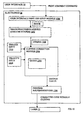
Fig. 12 illustrates a plurality of software modules in theelectronics 26 ofFig. 1B . The software modules receive commands from theuser interface 30 and control thelaser 12. The software modules include a user interface print job setup module 1200 (hereinafter "print job setup module 1200"), an image processing module 1202, aclipping correction module 1204, and real-time printing routines/drivers 1206. -
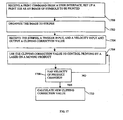
Fig. 17 illustrates a method of using the software modules inFig. 12 . In general, the print job setup module 1200 receives a print command from theuser interface 30, sets up a print job as an image (e.g., list of points with an order of the points to be marked) inblock 1700, and sends the image to be printed to the image processing module 1202. The image may be a code or sequence of symbols, such as one or two dimensional barcodes, corporate logos and product signs, or characters, such as Roman-language-based alphanumeric characters, Asian characters and Arabic characters. - The image processing module 1202 organizes the image to stripes (described below) in
block 1702 and sends thestripes 1208 to theclipping correction module 1204. Alternatively, the image processing module 1202 sends thestripes 1208 to a first-in-first-out queue, which is accessed by theclipping correction module 1204. Theclipping correction 1204 receives thestripes 1208, atrigger input 1210, and avelocity input 1212 and outputs a Clipping Correction Value (described below) to the real-time printing routines/drivers 1206 inblock 1704. The real-time printing routines/drivers 1206 uses the value to control printing by thelaser 12 on a moving product inblock 1706. - In
block 1708, theclipping correction module 1204 or the printing routines/drivers 1206 determines whether a velocity of the product has changed. If the velocity has changed, theclipping correction module 1204 determines a new Clipping Correction Value inblock 1710. - In another embodiment, the images may be stored in the
laser electronics 26. Theuser interface 30 may retrieve the images to display to a user to select, confirm or edit. -
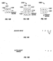
Figs. 13A-13C illustrate examples of stripes created by the image processing module 1202 ofFig. 12 . "Striping" refers to organizing an image (e.g., a list of points with an order of the points to be marked) of symbols or characters, such as "A B C," to a plurality of stripes or segments of data sets, as shown inFigs. 13A-13C . The image processing module 1202 organizes an image to stripes in a direction perpendicular to the motion of the product 22 (Fig. 11A ). In the description above, theproduct 22 travels horizontally with respect to the printing system 10 (Figs. 3A-3C ). Thus, the image processing module 1202 organizes an image into vertical stripes.Figs. 13A and 13B show vertical stripes created for aproduct 22 that travels horizontally with respect to theprinting system 10.Fig. 13A shows a top line of characters "A B C" and a bottom line of characters "1 2 3," which are organized to threevertical stripes Fig. 13B shows a top line of characters "1 2 3 4," a middle line of characters "A B," and a bottom line of characters "5 6 7 8," which are organized to six vertical stripes 1312-1322. -
Fig. 13C shows a top line of characters "A B C" and a bottom line of characters "1 2 3," which are organized to twohorizontal stripes printing system 10. - The image processing module 1202 places each symbol or character in one stripe, and does not divide a symbol into multiple stripes. For example, the symbol "3" in
Fig. 13B is properly placed in onestripe 1314 and should not be divided into multiple stripes, such asstripes Fig. 13B is divided intomultiple stripes Fig. 14C . - Also, the image processing module 1202 avoids placing more than one symbol (along a horizontal line of symbols) into a single vertical stripe. For example, if "3" and "4" in
Fig. 13B are put in one stripe, and "1" and "2" are put in another stripe, then the clipping correction "spreading" (described below) would result in an image of: - "1 2 3 4"
- If each symbol of a horizontal line of symbols (e.g., " 1 2 3 4" in
Fig. 13B ) are properly placed into its own vertical stripe, as shown inFigs. 13A and 13B , then the clipping correction spreading described below would result in a properly corrected image, such as the image inFig. 14C . - Each stripe may be assigned parameters, such as a print order and a "weigh" based on size/width, location, number of pixels, and time to print the stripe. Weight may represent the time it takes to print a stripe. In one configuration, weight of a stripe is expressed as follows in units of time:
-

- Thus, the image processing module 1202 in
Fig. 12 may output (a) a plurality ofstripes 1208 for a particular image to be printed, (b) a print order of thestripes 1208, and (c) a weight of each stripe to theclipping correction module 1204. - In one configuration, the image processing module 1202 in
Fig. 12 may sendstripes 1208 for a particular print job to theclipping correction module 1204 at any time before the print job actually begins (i.e., "off-line" time, not real-time). In another configuration, the image processing module 1202 may sendstripes 1208 for a particular print job to theclipping correction module 1204 in real-time. - Leading Edge Clipping Correction
-
Fig. 14A illustrates an example of a desired image to be printed.Fig. 14B illustrates an example of a printed image that is affected by "leading edge" clipping. "Leading edge" clipping may occur when (a) aproduct 22 is moving too fast past the laser print window or aperture 1502 (Fig. 15A ), and thelaser 12 cannot complete its printing, and/or (b) theprinting system 10 needs a high laser dwell time (explained above) to print each pixel on a product's material, and thelaser 12 cannot complete its printing. The left end of an image is "clipped" (Fig. 14B ) by the leading edge 1506 (Fig. 15A ) of the laser'saperture 1502, which limits the print beam 14 (Fig. 1A ) from reaching a desired location on the movingproduct 22. In other words, theprinting system 10 "runs out" of aperture when trying to print on a fast-movingproduct 22 or when a high dwell time is needed. -
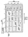
Fig. 15A illustrates an example of leading edge clipping. InFig. 15A , the location of a desired print zone 1504 on a product moves from left to right past aprinting aperture 1502 as time transpires (vertical axis). The time axis (vertical axis) inFig. 15A may be in seconds, microseconds or any other desired units. Distance is measured on the horizontal axis in microns, DAC (digital-to-analog converter) steps or any other desired units.Fig. 15B illustrates the intended code "1 2 3 4" to be printed in the desired print zone 1504 according to the distance scale inFig. 15A . Theprint zones 1504A-1504E inFig. 15A may be considered snapshots in time. - At time 2.5 in
Fig. 15A , a portion of theprint zone 1504A has entered theaperture 1502, and theprinting system 10 begins to print the fourth stripe "4" (process block 1508). Theblock 1508 represents a total time (vertically) and a total linear distance (horizontally) needed to print the fourth stripe "4" in real time. At time 4.5, thefull print zone 1504B is within theaperture 1502, and theprinting system 10 begins to print the third stripe "3" (process block 1510). At time 6.5, thefull print zone 1504C is still within theaperture 1502, and theprinting system 10 begins to print the second stripe "2" (process block 1512). But before theprinting system 10 can finish printing the second stripe "2," theprint zone 1504D has moved past aleading edge 1506 of theaperture 1502. Thus, the second stripe "2" is clipped. This is known as "leading edge clipping." Theprinting system 10 cannot print the first stripe "1" in the desiredprint zone 1504E because theprint zone 1504E has moved past theaperture 1506. - The
clipping correction module 1204 ofFig. 12 prevents "leading edge" clipping and ensures that an entire image (Fig. 14C ) is printed. Thetrigger input 1210 comes from the print trigger (sensor) 38 (described above with reference toFigs. 3A-3C and11A ), which senses a leading edge of aproduct 22. When theclipping correction module 1204 receives atrigger input 1210 to print a new job, this job is put into a clippingcorrection processing queue 1205. Theclipping correction module 1204 continually polls thequeue 1205 and runs clipping correction on the next job ready to print. In one embodiment, theclipping correction module 1204 only uses thestripes 1208 andvelocity 1212, and does not calculate time. Thequeue 1205 allows a trigger to be received while theclipping correction module 1204 is running clipping correction for a previously triggered print job. Theclipping correction module 1204 calculates a Clipping Correction Value (described below) for a code (sequence of symbols) to be printed in "real-time." Once theclipping correction module 1204 finishes the print job from the last trigger, it will start running clipping correction for the next print job in thequeue 1205. - The printing routines/
drivers 1206 andlaser 12 know when to start printing by tracking the distance of a product using an "encoder" 41 inFig. 11A . The encoder 41 may include a cylinder (with mechanical and electrical parts) and a wheel attached or in contact with the movingproduct line 36 inFig. 11A . The encoder 41 may be coupled to thelaser 12 and/orelectronics 26 via a cable and send signals to thelaser 12 and/or theelectronics 26. The encoder 41 may track speed and distance, which includes the distance d1 + d2 between the trigger eye/sensor 38 and the center of theaperture 14 inFig. 11A . The user sets the trigger distance while taking into account the desired location of theprint zone 34 on theproduct 22. Given the desiredprint zone 34 on theproduct 22 inFig. 11A , left of thelaser unit 10, the trigger distance plus distance to the print zone may be expressed as d1+d2+d3. Thelaser 12 will start to print when the product's position has traveled the "Trigger Distance" (set by the user) minus the "Start Offset" set by theclipping correction module 1204 from the trigger location. The user may input the "Trigger Distance" (e.g., d1 + d2 inFig. 11A between theprint trigger 38 and a center of theaperture 1502 inFig. 15A of the printing system 10) into the electronics 26 (Figs. 1B and12 ). - A user or technician may input a length of the
product 22 into theelectronics 26, or alternatively, theprinting system 10 may sense the length of theproduct 22 and store the length in theelectronics 26. In another configuration, neither the user nor the electronics enters the length of the product. Theelectronics 26 does not know the length of theproduct 22, and theclipping correction module 1204 does not know if the clipping correction value pushes/spreads the stripes past the length of the product. If this happens then some of the stripes will simply miss the product. - The
clipping correction module 1204 also receives avelocity input 1212 from the speed sensor 42 (e.g., encoder 41) inFigs. 3B-3C . As described above, thespeed sensor 42 senses the speed of theproduct 22 on theproduct line 36. Theclipping correction module 1204 ofFig. 12 uses the known distance of the product 22 (d1 + d2 inFig. 11A ) when thetrigger input 1210 is received and thevelocity input 1212 in the following equation to calculate the time when theproduct 22 will be in front of the aperture 1502:
- for a Stripe n:

- "Stripe Print Time" may be used to find "Stripe Travel Distance":

- "Stripe Travel Distance" may be used to find "Trailing Edge Clipping Position" and "Lead Edge Clipping Position" of the stripe:

- "Stripe Static TEC Position" is the trailing edge of the stripe if the entire code was printed in the aperture with zero velocity. This means every stripe had zero "Stripe Travel Distance." For example, if the
print zone 1504A inFig. 15A was centered in theaperture 1502, then the left side of each stripe is the "static TEC," and the right side of each stripe is the "static LEC." - An example of Σ(from i=0 up to i=(n-1)) [ Stripe Travel Distancei ] where n = 2 and n = 3 is now described. For TEC2 (TEC value of stripe 2 (n = 2) in
Fig. 15B ), theclipping correction module 1204 takes the "static TEC" ofstripe 2 and adds the travel distance of all previous stripes, which is the stripe travel distance ofstripe 1. For TEC3 (TEC value of stripe 3 (n = 3) inFig. 15B ) ), theclipping correction module 1204 takes the "static TEC" forstripe 3 and adds the travel distance of all previous stripes, which is the stripe travel distances ofstripes 
- "LEC" may be used to find "Start Offset" (described below):

- The "Clipping Correction Value" (described below) may be calculated as follows:

Where Σ represents a summation with j, and k as integer variables in the formula. The equation adds the result of (LECj - TECk - Aperture Size) / (j-k) when k = 0 and j = (Total Number of Stripes -1) with the result of(LECj - TECk - Aperture Size) / (j-k) when k = 0 and j = ((Total Number of Stripes -1 ) -1 ), and so on until j = k = 0. The equation takes that value and adds it to the result of the same process with k = 1. The equation repeats this until k reaches (Total Number of Stripes - 2). - The
clipping correction module 1204 uses (a) the weight of the stripes (time) and (b) the velocity input 1212 (V = distance/time) from the speed sensor 42 (e.g., the encoder 41) to calculate a minimal amount of "spreading" between printing consecutive/adjacent stripes to fit every stripe in a desired print zone on the product. The result of Time x (Distance/Time) is distance. "Spreading" allows each stripe to be printed on the product 22 (Fig. 14C ) as theproduct 22 passes through the aperture 1502 (Fig. 15A ). Spreading adds equal visual spaces S1 (Fig. 14C ) between adjacent stripes such that adjacent stripes are equidistant across an entire printed image. The reason for spreading is to push all stripe print zones back into the aperture by an equal amount while they are printing. This prevents the stripes from running into the aperture wall and clipping (Fig. 14B ). Pushing the print zones of the stripes back in the aperture results in visual spaces between the stripes seen on the product. The added spaces S1, S2, S3 shown inFigs. 14C-14E may appear exaggerated compared to actual added spaces to better illustrate clipping correction spreading. -
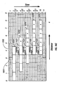
Fig. 15C illustrates an example of leading edge clipping correction and spreading. Theclipping correction module 1204 takes the final locations of all stripe print zones (with clipping correction), centers them in theaperture 1502, and determines the "Start Offset." The "Start Offset" is the distance between the original start location of the leading stripe in the aperture (generated by the image processing module 1202) and the position of the leading stripe's final start location after clipping correction. The leading stripe is the first stripe (e.g., "4" inFig. 15C ) that would enter theaperture 1502 as if the first stripe was a target on a moving product. - All the stripes are moved back into the
aperture 1502 by an equal amount equal to the Clipping Correction Value (described above) in units of distance or length. For example, theprinting system 10 moves the desired location on theproduct 22 where the third stripe "3" will be printed to the left by the Clipping Correction Value. As a result, theclipping correction module 1204 moves locations where stripes "2" and "1" will be printed back into theaperture 1502. The length of theaperture 1502 is accessible or programmed into theclipping correction module 1204. - At time 2.5 in
Fig. 15C , a sufficient portion of theprint zone 1520A enters theaperture 1502 for theprinting system 10 to begin printing the fourth stripe "4" (process block 1522).Block 1522 represents a total time (vertically) and a total linear distance (horizontally) to print the fourth stripe "4" in real time. At time 4.5, a larger portion of theprint zone 1520B is within theaperture 1502, and theprinting system 10 begins to print the third stripe "3" (process block 1524). At time 6.5, thefull print zone 1520C is within theaperture 1502, and theprinting system 10 begins to print the second stripe "2" (process block 1526). At time 8.5, thefull print zone 1520D is still within theaperture 1502, and theprinting system 10 begins to print the first stripe "1" (process block 1528). At time 9.5, all four stripes "1 2 3 4" have been printed in theprint zone 1520E, which has moved partially outside theaperture 1502. -
Fig. 15D illustrates the corrected (spread) code "1 2 3 4" printed in the desiredprint zone 1520E according to the distance scale inFig. 15C . The corrected (spread) code "1 2 3 4" ofFig. 15D is longer than the initial intended code inFig. 15B due to the added spaces, but each stripe is legible inFig. 15D with no clipping. - Even if the weight of each stripe is different, the space S1 (
Figs. 14C and15D ) between each symbol may be the same. - The
clipping correction module 1204 may calculate the minimum space S1 to fit all the stripes in the desired print zone 1520 and use as little space on the product as possible. Minimizing the space S1 improves legibility of the sequence of symbols and limits distortion. - The
clipping correction module 1204 outputs the Start Offset value to the printing routines/drivers 1206. The printing routines/drivers 1206 are tracking the encoder 41 (Fig. 11A ) to know when to start printing. The start offset value will cause the printing routines/drivers 1206 to start printing sooner than the "Trigger Distance" (set by the user) by an amount equal to the "start offset." Theclipping correction module 1204 also outputs another value to the real-time printing routines/drivers 1206: the Clipping Correction Value, which indicates the offset for in-between stripes (Figs. 14C ,15C and15D )) to adjust for clipping while printing. The printed image ofFig. 14C may be spread horizontally, but it is still readable. -
Fig. 15E illustrates clipping correction (process blocks 1540-1546) configured to enable a laser to be mostly centered in anaperture 1502 while printing four stripes "1 2 3 4." - Trailing Edge Clipping Correction
- "Trailing edge clipping" may occur when the
printing system 10 tries to (a) print an image on aproduct 22 that is moving too slow, and/or (b) print a long horizontal image on aproduct 22, e.g., total length of image is longer than theaperture 1502, The desired print location on theproduct 22 to print a symbol of the image does not enter the aperture 1502 (Fig. 16A ) on time as expected, and the "trailing edge" 1600 of theaperture 1502 limits theprint beam 14 from reaching the desired location on theproduct 22. As a result, one or more symbols of the image are printed in the wrong location on theproduct 22 or symbols are printed on top of each other (overlapping symbols), as shown inFig. 16A . -
Fig. 16A illustrates an example of trailing edge clipping. InFig. 16A , the location of a desired print zone 1602 on a product moves from left to right past aprinting aperture 1502 as time transpires (vertical axis). The time axis (vertical axis) inFig. 16A may be in seconds, microseconds or any other desired units. Distance is measured on the horizontal axis in microns, DAC (digital-to-analog converter) steps or any other desired units.Fig. 16B illustrates the intended code "1 2 3 4" to be printed in the desired print zone according to the distance scale inFig. 16A . - At time 2.5 in
Fig. 16A , a sufficient portion of theprint zone 1602A has entered theaperture 1502 for theprinting system 10 to print the fourth stripe "4" (process block 1604). Theblock 1604 represents a total time (vertically) and a total linear distance (horizontally) needed to print the fourth stripe "4" in real time. At time 4.5, theprint zone 1602B has only moved slightly more within theaperture 1502 compared to theprint zone 1602A at time 2.5. The desired location to print the third stripe "3" has not fully entered theaperture 1502. Theprinting system 10 begins to print the third stripe "3" (process block 1606). The third printed stripe "3" may overlap the fourth printed stripe "4." This is known as "trailing edge clipping." At time 6.5, theprint zone 1602C has only moved slightly more within theaperture 1502 compared to theprint zone 1602B at time 4.5. Theprinting system 10 begins to print the second stripe "2" (process block 1608). The second printed stripe "2" may overlap the third printed stripe "3" At time 8.5, theprint zone 1602D has only moved slightly more within theaperture 1502 compared to theprint zone 1602C at time 6.5. Theprinting system 10 begins to print the first stripe "1" (process block 1610). The first printed stripe "1" may overlap the second printed stripe "2." -
Fig. 16C illustrates an example of trailing edge clipping correction, which adds time delays between printing stripes. Theclipping correction module 1204 provides real-time trailing edge clipping correction to print stripes on aproduct 22 moving at a slow speed or to print stripes of codes that are longer than theaperture 1502. Trailing edge clipping correction turns off thelaser 12 and delays printing until a proper location (print zone for a stripe) on theproduct 22 has entered theaperture 1502. Theclipping correction module 1204 uses the following equation to derive a time delay when a desired print zone will enter the aperture 1502: -

- In one configuration, the
clipping correction module 1204 adds time delays to start printing a stripe when the desired stripe location is substantially centered in theaperture 1502. - At time 2.5 in
Fig. 16C , a sufficient portion of theprint zone 1620A enters theaperture 1502 for theprinting system 10 to begin printing the fourth stripe "4" (process block 1622).Block 1622 represents a total time (vertically) and a total linear distance (horizontally) to print the fourth stripe "4" in real time. At time 4.5, a sufficient portion of theprint zone 1620B is within theaperture 1502 for theprinting system 10 to begin printing the third stripe "3" (process block 1624). At time 6.5, a sufficient portion of theprint zone 1620C is within theaperture 1502 for theprinting system 10 to begin printing the second stripe "2" (process block 1626). At time 8.5, a sufficient portion of theprint zone 1620D is within theaperture 1502 for theprinting system 10 to begin printing the first stripe "1" (process block 1628). At time 9.5, all four stripes "1 2 3 4" have been printed in theprint zone 1620E, which has moved partially outside theaperture 1502. - The result of the trailing edge clipping correction in
Fig. 16C is the same as the desired image to be printed inFig. 16B . There are no added spaces. - The distance that the
product 22 travels while printing a stripe is equal to the stripe width with clipping correction. - Update Clipping Correction
- After the leading edge of the
product 22 has moved past the trigger 38 (Fig. 11A ), theclipping correction module 1204 or the real-time printing routines/drivers 1206 may reevaluate thevelocity input 1212 between every printed stripe. If the velocity of the product has changed, theclipping correction module 1204 updates the Clipping Correction Value in real-time. For example, if theclipping correction module 1204 senses that the velocity of theproduct 22 has increased while or after thelaser 12 prints the "4" inFig. 14C , theclipping correction module 1204 may update, i.e., increase, the Clipping Correction Value to increase spreading.Fig. 14D shows increased spreading due to updated clipping correction. Each printed symbol inFig. 14D is now separated by an equal space S2, which is larger than space S1. The time to print the image inFig. 14C is the same as the time to print the image inFig. 14D , since the velocity of the product and the distance of the image have changed inFig. 14D . - If the
clipping correction module 1204 senses that the velocity of theproduct 22 has increased again while or after thelaser 12 prints the "3" inFig. 14D , theclipping correction module 1204 may further update, i.e., further increase, the Clipping Correction Value to increase spreading.Fig. 14E shows increased spreading due to update clipping correction. Space S3 between "2" and "3" is larger than space S2 between "4" and "3" to accommodate the increased velocity sensed during or after printing of "3." Thus, theclipping correction module 1204 attempts to insert equal spaces (S1 inFig. 14C or S2 in - In one configuration, the
clipping correction module 1204 does not reduce spreading if the sensed velocity of theproduct 22 decreases. For example, if theclipping correction module 1204 senses that the velocity of theproduct 22 is decreasing while or after thelaser 12 prints the "3" inFig. 14D , theclipping correction module 1204 does not decrease the Clipping Correction Value sent to the printing routines/drivers 1206. Theprinting system 10 will still print the image inFig. 14D with equal spaces S2 between characters. Thus, spacing between characters may increase but not decrease to preserve the highest quality image, in this configuration of theprinting system 10. - If the velocity of the product decreases, the
clipping correction module 1204 adds a time delay to wait for a desired print zone to enter theaperture 1502 before printing the next symbol. -
Figs. 18A-18C illustrate examples of asign 1800, abar code 1802 and acompany logo 1804, respectively, which may be marked with the software modules and electronics inFig. 12 . The software modules and electronics inFig. 12 may print other signs, bar codes, logos and images using the striping methods described above. - Although the present application has been described in detail, it should be understood that various changes, combinations, substitutions and alterations can be made hereto without departing from the scope of the application as described by the appended claims.
Claims (41)
- A system (10) comprising:a laser source (12) to print an image (1800;1802;1804) on a moving object (22);an input module to receive information identifying a velocity of the moving object (22) and an initial position of the moving object (22) relative to the laser source; anda processor to perform operations including:characterised in that the processor is further arranged to perform the operations of:separating an image to be printed on the moving object (22) into a plurality of stripes (1302-1306;1312-1322;1332-1334) that collectively represent the image to be printed;based on one or more of (a) the velocity of the moving object (22), (b) the initial position of the moving object (22) relative to the laser source, and (c) a parameter of a stripe to be printed, determining at least one of a time to print the stripe and a location on the moving object at which to print the stripe; andcontrolling the laser source (12) to print the stripe on the moving object (22) according to at least one of the time and location values;calculating a clipping correction value in the form of either an interstripe distance, to ensure printing of the entire image is completed, or an interstripe time delay, to ensure stripes of the image are printed at proper locations; andusing the clipping correction value to control printing by the laser source (12) on the moving object (22).
- The system (10) of claim 1, further comprising a sensor (31;42;38) adapted to sense an object moving past the sensor, the sensor providing said information identifying the initial position of the moving object.
- The system (10) of claim 1 or claim 2, wherein the initial position of the moving object comprises a pre-determined distance away from a measuring point (92) on the system (10).
- The system (10) of any one of the preceding claims, wherein the time to print comprises a print start time.
- The system (10) of any one of the preceding claims, wherein the location at which to print comprises a print start location.
- The system (10) of any one of the preceding claims, wherein the parameter of the stripe to be printed comprises one or more of a print order, a stripe size, a stripe location, and a number of pixels.
- The system (10) of any one of the preceding claims, wherein the processor is arranged to repeat the determining and print controlling for each of the stripes collectively representing the image (1800;1802;1804).
- The system (10) of any one of the preceding claims, wherein the processor is arranged to vary at least one of time and location to print between printing of successive stripes.
- The system (10) of any one of the preceding claims, further comprising a sensor to detect a velocity of the moving object (22).
- The system (10) of any one of the preceding claims, wherein a trigger input indicates a time when the moving object (22) is at a pre-determined distance from a measuring point (92) on the system (10).
- The system (10) of any one of the preceding claims, wherein the laser source (12) is less than 30 Watts.
- Software or firmware for implementing in the system of any of claims 1 to 11, comprising:a first module arranged to organize the image to be printed on the moving object by the laser source into the plurality of stripes that collectively represent the image; anda second module arranged to receive the stripes, a trigger input indicating the initial position of the moving object relative to the laser source and a velocity input indicating the velocity of the moving object todetermine at least one of (a) locations on the moving object (22) to print the stripes, and (b) a time at which to print at least one stripe on the moving object (22); andcalculate the clipping correction value in the form of either an interstripe distance, to ensure printing of the entire image is completed, or an interstripe time delay to ensure stripes of the image are printed at proper locations.
- The software or firmware of claim 12, wherein the system further comprises a storage medium and the first module and the second module are stored in the medium and executable, by the processor.
- The software or firmware of claim 12 or claim 13, wherein the image comprises a sequence of symbols and the first module is arranged to separate symbols of the image into the plurality of stripes, each stripe comprising at least one whole symbol.
- The software or firmware of any one of claims 12 to 14, wherein the first module is arranged to separate symbols of the image into the plurality of stripes, each stripe comprising a plurality of whole symbols with substantially a same position in a direction orthogonal to a direction of motion of the moving object (22).
- The software or firmware of any one of claims 12 to 15, further comprising a third module to receive an output from the second module to control the laser source (12).
- The software or firmware of claim 16, wherein the second module is arranged to send the clipping correction value to the third module, the second module being adapted to output an updated clipping correction value to the third module when the velocity input changes.
- The software or firmware of any one of claims 12 to 17, wherein the second module is arranged to calculate a start offset distance on the object (22) to print a first stripe.
- The software or firmware of any one of claims 12 to 18, wherein the second module is arranged to calculate a distance on the object (22) between printing consecutive stripes.
- The software or firmware of any one of claims 12 to 19, wherein the second module is arranged to calculate a time delay between printing consecutive stripes.
- A method comprising:organizing an image (1800;1802;1804) to be printed on a moving object by a laser beam into a plurality of stripes (1302-1306;1312-1322:1332-1334) that collectively represent the image;based on one or more of (a) a velocity of the moving object (22), (b) an initial position of the moving object (22) relative to the laser beam and (c) a parameter of a stripe to be printed, determining at least one of a time to print the stripe and a location on the moving object at which to print the stripe; andprinting the stripe with the laser beam (14) on the moving object (22) based on at least the determined time to print and the location;characterised in that the method further comprises:calculating a clipping correction value in the form of either an interstripe distance, to ensure all stripes of the image are printed, or an interstripe time delay, to ensure stripes of the image are printed at desired stripe locations; andusing the clipping correction value to control printing by the laser beam (14) on the moving object (22).
- The method of claim 21, further comprising receiving an input relating to at least one of the velocity of the moving object (22) and the initial position of the moving object (22).
- The method of claim 21 or claim 22, further comprising receiving an input indicating the initial position of the moving object (22).
- The method of any one of claims 21 to 23, wherein the determined location comprises a starting location for printing.
- The method of any one of claims 21 to 24, wherein the determined time comprises a starting time for printing.
- The method of any one of claims 21 to 25, wherein the parameter of the stripe to be printed comprises one or more of a print order, a stripe size, a stripe location, and a number of pixels.
- The method of any one of claims 21 to 26, further comprising repeating the determining and printing for each of the stripes collectively representing the image (1800,1802;1804).
- The method of any one of claims 21 to 27, wherein print location and/or time are varied between printing of successive stripes.
- The method of any one of claims 21 to 28, wherein the image (1800;1802;1804) to be printed is a list of points with an order of the points to be marked.
- The method of any one of claims 21 to 29, further comprising receiving a print command from a user interface (30) and setting up a print job as an image.
- The method of any one of claims 21 to 30, further comprising determining whether a velocity of the object (22) has changed, and if the velocity has changed, further modifying at least one of (a) a location on the moving object (22) to print at least one stripe, and (b) a time to print at least one stripe on the moving object (22).
- The method of any one of claims 21 to 31, wherein the image comprises a sequence of symbols.
- The method of any one of claims 21 to 32, further comprising separating symbols of the image into a plurality of stripes, each stripe comprising at least one whole symbol.
- The method of any one of claims 21 to 33, further comprising separating symbols of the image into a plurality of stripes, each stripe comprising a plurality of whole symbols with substantially a same position in a direction orthogonal to a direction of motion of the moving object (22).
- The method of any one of claims 21 to 34, further comprising detecting a velocity of the moving object (22).
- The method of any one of claims 21 to 35, further comprising steering a beam (14) from the laser (12).
- The method of any one of claims 21 to 36, further comprising generating an updated clipping correction value when the velocity input changes.
- The method of any one of claims 21 to 37, further comprising calculating a start offset distance on the object (22) to print a first stripe.
- The method of any one of claims 21 to 38, further comprising calculating a time delay between printing consecutive stripes.
- The method of any one of claims 21 to 39, further comprising calculating a leading edge correction value.
- The method of any one of claims 21 to 40, further comprising calculating a trailing edge correction value.
Applications Claiming Priority (2)
| Application Number | Priority Date | Filing Date | Title |
|---|---|---|---|
| US10/741,930 US7046267B2 (en) | 2003-12-19 | 2003-12-19 | Striping and clipping correction |
| PCT/US2004/042785 WO2005062833A2 (en) | 2003-12-19 | 2004-12-17 | Striping and clipping correction |
Publications (3)
| Publication Number | Publication Date |
|---|---|
| EP1697140A2 EP1697140A2 (en) | 2006-09-06 |
| EP1697140A4 EP1697140A4 (en) | 2007-06-13 |
| EP1697140B1 true EP1697140B1 (en) | 2010-02-24 |
Family
ID=34678308
Family Applications (1)
| Application Number | Title | Priority Date | Filing Date |
|---|---|---|---|
| EP04814917A Active EP1697140B1 (en) | 2003-12-19 | 2004-12-17 | Striping and clipping correction |
Country Status (6)
| Country | Link |
|---|---|
| US (1) | US7046267B2 (en) |
| EP (1) | EP1697140B1 (en) |
| JP (1) | JP5066696B2 (en) |
| DE (1) | DE602004025737D1 (en) |
| ES (1) | ES2339669T3 (en) |
| WO (1) | WO2005062833A2 (en) |
Families Citing this family (16)
| Publication number | Priority date | Publication date | Assignee | Title |
|---|---|---|---|---|
| US9299196B2 (en) * | 2004-12-22 | 2016-03-29 | Pitney Bowes Inc. | Method and system for high speed printing using drop-on demand technology that compensates for droplet satellites |
| IT1391351B1 (en) * | 2008-10-06 | 2011-12-13 | Gd Spa | PACKAGE LASER MARKING UNIT. |
| US8571077B2 (en) | 2010-08-31 | 2013-10-29 | First Solar, Inc. | System and method for laser modulation |
| EP2565994B1 (en) | 2011-09-05 | 2014-02-12 | ALLTEC Angewandte Laserlicht Technologie Gesellschaft mit beschränkter Haftung | Laser device and method for marking an object |
| DK2564973T3 (en) * | 2011-09-05 | 2015-01-12 | Alltec Angewandte Laserlicht Technologie Ges Mit Beschränkter Haftung | Marking apparatus having a plurality of lasers and a kombineringsafbøjningsindretning |
| EP2564972B1 (en) * | 2011-09-05 | 2015-08-26 | ALLTEC Angewandte Laserlicht Technologie Gesellschaft mit beschränkter Haftung | Marking apparatus with a plurality of lasers, deflection means and telescopic means for each laser beam |
| ES2530070T3 (en) * | 2011-09-05 | 2015-02-26 | ALLTEC Angewandte Laserlicht Technologie Gesellschaft mit beschränkter Haftung | Marking apparatus with a plurality of individually adjustable lasers and sets of deflection means |
| DK2565996T3 (en) | 2011-09-05 | 2014-01-13 | Alltec Angewandte Laserlicht Technologie Gmbh | Laser device with a laser unit and a fluid container for a cooling device of the laser unit |
| ES2438751T3 (en) | 2011-09-05 | 2014-01-20 | ALLTEC Angewandte Laserlicht Technologie Gesellschaft mit beschränkter Haftung | Device and procedure for marking an object by means of a laser beam |
| EP2564974B1 (en) * | 2011-09-05 | 2015-06-17 | ALLTEC Angewandte Laserlicht Technologie Gesellschaft mit beschränkter Haftung | Marking apparatus with a plurality of gas lasers with resonator tubes and individually adjustable deflection means |
| EP2564976B1 (en) | 2011-09-05 | 2015-06-10 | ALLTEC Angewandte Laserlicht Technologie Gesellschaft mit beschränkter Haftung | Marking apparatus with at least one gas laser and heat dissipator |
| CN104245332B (en) * | 2012-04-20 | 2016-12-28 | 芬欧汇川集团 | For the method and apparatus manufacturing the marking in mobile web |
| US9073360B2 (en) * | 2012-08-29 | 2015-07-07 | Xerox Corporation | Systems and methods for printing differential gloss image on packaging |
| US10583668B2 (en) | 2018-08-07 | 2020-03-10 | Markem-Imaje Corporation | Symbol grouping and striping for wide field matrix laser marking |
| JP2020082171A (en) * | 2018-11-30 | 2020-06-04 | ブラザー工業株式会社 | Laser marker |
| JP6885388B2 (en) * | 2018-11-30 | 2021-06-16 | ブラザー工業株式会社 | Laser marker |
Family Cites Families (133)
| Publication number | Priority date | Publication date | Assignee | Title |
|---|---|---|---|---|
| US4675498A (en) | 1967-09-05 | 1987-06-23 | Lemelson Jerome H | Apparatus and method for coding objects |
| US4965829A (en) | 1967-09-05 | 1990-10-23 | Lemelson Jerome H | Apparatus and method for coding and reading codes |
| FR1561258A (en) | 1968-01-15 | 1969-03-28 | ||
| US3648601A (en) | 1969-06-02 | 1972-03-14 | Roger F Weidman | Code-marking mechanism |
| US3898417A (en) | 1969-12-22 | 1975-08-05 | Nat Steel Corp | Continuous strip encoding |
| US3725655A (en) | 1971-06-24 | 1973-04-03 | Ibm | Media transport performance measurements |
| US3714393A (en) | 1971-07-20 | 1973-01-30 | Gen Electric | System for producing a constant number of pulses per unit length of traveling strip |
| BE790341A (en) | 1971-10-29 | 1973-04-20 | Siderurgie Fse Inst Rech | |
| US3761675A (en) | 1972-01-19 | 1973-09-25 | Hughes Aircraft Co | Material cutting and printing system |
| US3803637A (en) | 1972-11-17 | 1974-04-09 | Ibm | Laser printer |
| US3885873A (en) | 1972-12-12 | 1975-05-27 | Stiftelsen Inst Mikrovags | Device for measuring the relative movement between two objects |
| US3848104A (en) | 1973-04-09 | 1974-11-12 | Avco Everett Res Lab Inc | Apparatus for heat treating a surface |
| US4049945A (en) | 1973-10-10 | 1977-09-20 | Winkler & Dunnebier Maschinenfabrik Und Eisengiesserei Kg | Method of and apparatus for cutting material to shape from a moving web by burning |
| US3863565A (en) | 1973-12-10 | 1975-02-04 | Corning Glass Works | Aratus for imprinting on moving articles without smearing the imprint |
| US3975261A (en) | 1974-01-02 | 1976-08-17 | Tac Technical Instrument Corporation | Sequential event memory circuit for process and quality control |
| US4024545A (en) | 1974-04-22 | 1977-05-17 | Mb Associates | Laser-excited marking system |
| GB1478759A (en) | 1974-11-18 | 1977-07-06 | Alza Corp | Process for forming outlet passageways in pills using a laser |
| JPS5726389B2 (en) | 1975-03-19 | 1982-06-04 | ||
| US4160894A (en) | 1975-05-14 | 1979-07-10 | Winkler & Dunnebier Maschinenfabrik Und Eisengiesserei Kg | Method and apparatus for the focal form cutting of a moving web of material by a laser beam |
| US4065212A (en) | 1975-06-30 | 1977-12-27 | International Business Machines Corporation | Inspection tool |
| US4011437A (en) | 1975-09-12 | 1977-03-08 | Cincinnati Milacron, Inc. | Method and apparatus for compensating for unprogrammed changes in relative position between a machine and workpiece |
| US4063064A (en) | 1976-02-23 | 1977-12-13 | Coherent Radiation | Apparatus for tracking moving workpiece by a laser beam |
| US4025752A (en) | 1976-05-25 | 1977-05-24 | Olin Corporation | Apparatus for electrically perforating dielectric webs |
| US4086522A (en) | 1976-09-08 | 1978-04-25 | Unimation, Inc. | Computer assisted teaching arrangement for conveyor line operation |
| US4099830A (en) | 1976-12-15 | 1978-07-11 | A. J. Bingley Limited | Optical systems including polygonal mirrors rotatable about two axes |
| US4100599A (en) | 1976-12-22 | 1978-07-11 | Ncr Canada Ltd. - Ncr Canada Ltee | Method and apparatus for determining velocity of a moving member |
| US4240017A (en) | 1977-07-21 | 1980-12-16 | Yoshino Kogyosho Co., Ltd. | Control method in an intermittently moving mechanism and a shift register for carrying out the method |
| US4106965A (en) | 1977-09-12 | 1978-08-15 | The Goodyear Tire & Rubber Company | Tire tread line stripping |
| US4154530A (en) | 1977-12-22 | 1979-05-15 | National Semiconductor Corporation | Laser beam error correcting process |
| US4271968A (en) | 1978-05-05 | 1981-06-09 | Geosource Inc. | Ejector dwell controller for a sorting apparatus |
| US4207985A (en) | 1978-05-05 | 1980-06-17 | Geosource, Inc. | Sorting apparatus |
| NO790519L (en) | 1978-06-21 | 1979-12-27 | Ahlstroem Oy | SPIRAL WRAPPED SLEEVE, METHOD FOR MANUFACTURING THE SLEEVE, PROCEDURE FOR USING THE SLEEVE IN A WRAPPING APPLIANCE AND DEVICE FOR USING THE SLEEVE |
| JPS5526563A (en) | 1978-08-16 | 1980-02-26 | Fuji Photo Film Co Ltd | Light beam scanner |
| US4404454A (en) | 1978-09-20 | 1983-09-13 | Philip Morris Incorporated | Light energy perforation apparatus and system |
| US4218606A (en) | 1978-10-03 | 1980-08-19 | Olin Corporation | Apparatus for perforating webs with high intensity, coherent radiation |
| DE2853258A1 (en) | 1978-12-09 | 1980-06-12 | Hoesch Werke Ag | METHOD AND ARRANGEMENT FOR APPLYING A MARKING ON THE SURFACE OF MOVING TABLES AND TAPES |
| US4283145A (en) | 1979-02-13 | 1981-08-11 | Kirin Beer Kabushiki Kaisha | Optical system for the detection of flaws in bottles or the like |
| US4297559A (en) | 1979-05-10 | 1981-10-27 | Olin Corporation | Apparatus for controlled perforation of moving webs with fixed focus laser beam |
| US4354196A (en) | 1979-05-24 | 1982-10-12 | Eocom Corporation | Laser engraving system with massive base table and synchronization controls |
| US4323755A (en) | 1979-09-24 | 1982-04-06 | Rca Corporation | Method of making a machine-readable marking in a workpiece |
| US4371782A (en) | 1979-12-31 | 1983-02-01 | Frans Brouwer | Optical pattern tracing system with remotely controlled kerf and forward offsets |
| GB2073639A (en) | 1980-02-20 | 1981-10-21 | Duracell Int | Apparatus and method for spot heat treating workpieces |
| US4375025A (en) | 1980-06-19 | 1983-02-22 | Automated Industrial Systems, Inc. | Laser strip marker |
| US4334471A (en) | 1980-08-18 | 1982-06-15 | Markem Corporation | Reference printing on moving surface |
| US4338114A (en) | 1980-08-21 | 1982-07-06 | Liberty Glass Company | Laser treatment method for imparting increased mechanical strength to glass objects |
| US4497995A (en) | 1982-04-15 | 1985-02-05 | Sws Incorporated | Apparatus for continuously advancing and welding metal can bodies and the like |
| US4590859A (en) | 1982-06-30 | 1986-05-27 | Monarch Marking Systems, Inc. | Method of printing by sensing variable indicia tag format length |
| US4468551A (en) | 1982-07-30 | 1984-08-28 | Armco Inc. | Laser treatment of electrical steel and optical scanning assembly therefor |
| JPS5935892A (en) | 1982-08-20 | 1984-02-27 | Nec Corp | Laser working device |
| US4560856A (en) | 1982-09-01 | 1985-12-24 | Westinghouse Electric Corp. | Pulsed laser machining apparatus |
| IL66817A0 (en) | 1982-09-16 | 1982-12-31 | Gaz Moshe | Special visual and sound effects in cinematography using beam lasers on positive and negative copies |
| US4480169A (en) | 1982-09-13 | 1984-10-30 | Macken John A | Non contact laser engraving apparatus |
| US4517436A (en) | 1982-09-20 | 1985-05-14 | Automated Industrial Systems | Laser marker for articles of manufacture |
| NL8204604A (en) | 1982-11-26 | 1984-06-18 | Wavin Bv | PLASTIC MATERIAL. |
| IL67599A (en) | 1982-12-31 | 1986-09-30 | Laser Ind Ltd | Control apparatus particularly useful for controlling a laser |
| US4734558A (en) | 1983-05-16 | 1988-03-29 | Nec Corporation | Laser machining apparatus with controllable mask |
| US4576286A (en) | 1983-06-27 | 1986-03-18 | Cochlea Corporation | Parts sorting systems |
| US4557386A (en) | 1983-06-27 | 1985-12-10 | Cochlea Corporation | System to measure geometric and electromagnetic characteristics of objects |
| US4870623A (en) | 1983-06-27 | 1989-09-26 | Cochlea Corporation | System to recognize a geometry parameter of unknown object with continuous wave acoustic energy |
| DE3333386A1 (en) | 1983-09-15 | 1985-04-11 | Siemens AG, 1000 Berlin und 8000 München | METHOD AND DEVICE FOR LABELING PARTS, ESPECIALLY ELECTRONIC COMPONENTS |
| FR2553910B1 (en) | 1983-10-24 | 1986-03-21 | Commissariat Energie Atomique | THERMOELECTRIC SENSOR FOR LASER BEAM ALIGNMENT AND SERVO DEVICE USING THE SAME, FOR AUTOMATIC ALIGNMENT OF A LASER BEAM |
| DE3406677A1 (en) | 1984-02-24 | 1985-09-05 | Fa. Carl Zeiss, 7920 Heidenheim | DEVICE FOR COMPENSATING THE EMISSION OF A LASER BEAM |
| US4636043A (en) | 1984-03-01 | 1987-01-13 | Laser Photonics, Inc. | Laser beam scanning device and marking system |
| DE3411797A1 (en) | 1984-03-30 | 1985-10-10 | Bayer Ag, 5090 Leverkusen | METHOD FOR LABELING PLASTIC PARTS |
| US4652722A (en) | 1984-04-05 | 1987-03-24 | Videojet Systems International, Inc. | Laser marking apparatus |
| WO1986000427A1 (en) | 1984-06-21 | 1986-01-16 | American Telephone & Telegraph Company | Deep-uv lithography |
| US4695698A (en) | 1984-07-10 | 1987-09-22 | Larassay Holding Ag | Method of, and apparatus for, generating a predetermined pattern using laser radiation |
| JPS6129029A (en) | 1984-07-19 | 1986-02-08 | 三菱電機株式会社 | Method of indicating terminal number or like in solenoid relay or like |
| US4725709A (en) | 1984-09-25 | 1988-02-16 | Siemens Aktiengesellschaft | Apparatus having a sweep arrangement for non-contacting modification of an article |
| AT382558B (en) | 1985-02-12 | 1987-03-10 | Kufstein Schablonentech Gmbh | METHOD AND DEVICE FOR PRODUCING A SCREEN PRINT TEMPLATE |
| US4638144A (en) | 1985-04-24 | 1987-01-20 | Automated Industrial Systems | Indexing laser marker |
| US4796038A (en) | 1985-07-24 | 1989-01-03 | Ateq Corporation | Laser pattern generation apparatus |
| DE3530189A1 (en) | 1985-08-23 | 1987-03-05 | Zeiss Carl Fa | DEVICE FOR CORRECTING THE POSITION OF A LASER BEAM GUIDED BY A JOINT OPTICS |
| CA1266318A (en) | 1985-10-07 | 1990-02-27 | Hiroshi Suzuki | High-speed packet-switched communications system with end-to-end flow control and retransmission |
| US4707709A (en) | 1986-01-17 | 1987-11-17 | Eastman Kodak Company | Image recording apparatus in which exposure levels are a function of image contents |
| AU584563B2 (en) | 1986-01-31 | 1989-05-25 | Ciba-Geigy Ag | Laser marking of ceramic materials, glazes, glass ceramics and glasses |
| JPS62187977A (en) | 1986-02-13 | 1987-08-17 | Dainippon Screen Mfg Co Ltd | Image data processor |
| EP0262225A4 (en) | 1986-03-26 | 1988-12-12 | Ni Ts Tekh Lazeram An | Installation for laser treatment of materials. |
| DE3614082A1 (en) | 1986-04-25 | 1987-10-29 | Elcede Gmbh | DEVICE AND METHOD FOR MAKING CUTS IN THE EXTERNAL SURFACES OF AT LEAST ONE BODY |
| US4696143A (en) | 1986-05-06 | 1987-09-29 | William P. Young Co. | Container capping apparatus |
| EP0274538B1 (en) | 1986-07-09 | 1992-12-02 | Matsushita Electric Industrial Co., Ltd. | Laser beam machining method |
| EP0316347B1 (en) | 1986-08-02 | 1990-07-18 | A. Nattermann & Cie. GmbH | Device and process for marking moulded items and tablets with laser beams |
| US4720618A (en) | 1986-08-07 | 1988-01-19 | Videojet Systems International, Inc. | Method and apparatus for equalizing power output in a laser marking system |
| US4727235A (en) | 1986-08-07 | 1988-02-23 | Videojet Systems International, Inc. | Method and apparatus for equalizing power output in a laser marking system |
| KR910000826B1 (en) | 1986-11-14 | 1991-02-09 | 미쓰비시덴기 가부시기가이샤 | Method of laser marking |
| US4736187A (en) | 1986-12-04 | 1988-04-05 | The Regents Of The University Of California | Encoder for measuring both incremental and absolute positions of moving elements |
| US4914437A (en) | 1986-12-04 | 1990-04-03 | Regents Of The University Of California | Encoder for measuring both incremental and absolute positions of moving elements |
| US4901073A (en) | 1986-12-04 | 1990-02-13 | Regent Of The University Of California | Encoder for measuring the absolute position of moving elements |
| GB8700765D0 (en) | 1987-01-14 | 1987-02-18 | Wiggins Teape Group Ltd | Laser apparatus |
| EP0276995B1 (en) | 1987-01-28 | 1994-03-30 | Mitsubishi Denki Kabushiki Kaisha | Method of forming identifying indicium on cathode ray tubes |
| US4758703A (en) | 1987-05-06 | 1988-07-19 | Estee Lauder Inc. | System and method for encoding objects |
| US5175425A (en) * | 1987-06-15 | 1992-12-29 | Leuze Electronic Gmbh & Co. | Process for marking semiconductor surfaces |
| US4803336A (en) | 1988-01-14 | 1989-02-07 | Hughes Aircraft Company | High speed laser marking system |
| JPH01245993A (en) | 1988-03-27 | 1989-10-02 | Semiconductor Energy Lab Co Ltd | Thin film working device |
| GB8809666D0 (en) | 1988-04-23 | 1988-05-25 | Amchem Co Ltd | Machining method & apparatus |
| US4941082A (en) | 1988-04-25 | 1990-07-10 | Electro Scientific Industries, Inc. | Light beam positioning system |
| US4918284A (en) | 1988-10-14 | 1990-04-17 | Teradyne Laser Systems, Inc. | Calibrating laser trimming apparatus |
| US4969134A (en) | 1988-10-24 | 1990-11-06 | Balderson R Bruce | Electro-optical signaling system |
| US4970600A (en) | 1989-04-04 | 1990-11-13 | Melco Industries, Inc. | Laser engraver with X-Y assembly and cut control |
| US4987287A (en) * | 1989-05-12 | 1991-01-22 | Prevent-A-Crime International, Inc. | Method of making a stencil for etching glass |
| US5087805A (en) * | 1990-07-06 | 1992-02-11 | Webcraft Technologies, Inc. | Printed and encoded mass distributable response piece and method of making the same |
| ES2013193A6 (en) * | 1989-06-07 | 1990-04-16 | Codilaser Sa | A system for marking moving objects by laser beams. |
| JP2937361B2 (en) * | 1989-09-29 | 1999-08-23 | 日本電気株式会社 | Laser processing machine |
| FR2652541B1 (en) * | 1989-10-04 | 1992-01-03 | Bongrain Sa | INSTALLATION FOR THE SURFACE LASER MARKING OF A CHEESE OR CHARCUTIER FOOD PRODUCT. |
| US5109149A (en) * | 1990-03-15 | 1992-04-28 | Albert Leung | Laser, direct-write integrated circuit production system |
| DE4126626C2 (en) * | 1990-08-15 | 1994-08-04 | United Distillers Plc | Marked material body and method for its production |
| US5132510A (en) * | 1990-09-04 | 1992-07-21 | Trumpf, Inc. | Laser machine assembly for flow of workpieces therethrough and method of using same |
| US5327529A (en) * | 1990-09-24 | 1994-07-05 | Geoworks | Process of designing user's interfaces for application programs |
| US5653900A (en) * | 1991-01-17 | 1997-08-05 | United Distillers Plc | Dynamic laser marking |
| US5294942A (en) * | 1991-07-22 | 1994-03-15 | Eastman Kodak Company | Non-impact printer apparatus and method for recording on a moving medium |
| US5229574A (en) * | 1991-10-15 | 1993-07-20 | Videojet Systems International, Inc. | Print quality laser marker apparatus |
| US5229573A (en) * | 1991-10-15 | 1993-07-20 | Videojet Systems International, Inc. | Print quality laser marker apparatus |
| US5283773A (en) * | 1992-06-10 | 1994-02-01 | Iomega Corporation | Steering laser beam while etching optical servo tracks for magnetic disks |
| EP0671239A4 (en) * | 1992-11-25 | 1996-08-28 | Komatsu Mfg Co Ltd | Laser marking apparatus and method. |
| DE4241663C2 (en) * | 1992-12-04 | 1997-05-28 | Borus Spezialverfahren | Procedure for marking and recognizing an object |
| US5329090A (en) * | 1993-04-09 | 1994-07-12 | A B Lasers, Inc. | Writing on silicon wafers |
| GB2281129B (en) * | 1993-08-19 | 1997-04-09 | United Distillers Plc | Method of marking a body of glass |
| US20030011672A1 (en) * | 1993-11-09 | 2003-01-16 | Markem Corporation, New Hampshire Corporation | Scanned marking of workpieces |
| DE69424852T2 (en) * | 1993-12-03 | 2000-11-09 | Keyence Corp Takatsuki | Laser scanning marking device |
| JP2565096Y2 (en) * | 1993-12-03 | 1998-03-11 | 株式会社キーエンス | Laser marking device |
| US5515480A (en) * | 1994-06-15 | 1996-05-07 | Dp-Tek, Inc. | System and method for enhancing graphic features produced by marking engines |
| JPH08179752A (en) * | 1994-12-21 | 1996-07-12 | Canon Inc | Image processing device and method |
| DE19606782C1 (en) * | 1996-02-23 | 1998-01-08 | Orga Kartensysteme Gmbh | Method for producing a chip card and chip card produced therewith |
| US5751436A (en) * | 1996-12-23 | 1998-05-12 | Rocky Mountain Instrument Company | Method and apparatus for cylindrical coordinate laser engraving |
| US5906609A (en) * | 1997-02-05 | 1999-05-25 | Sahar Technologies | Method for delivering energy within continuous outline |
| JPH1133753A (en) * | 1997-07-15 | 1999-02-09 | Fuji Electric Co Ltd | Laser marking device |
| US6424430B1 (en) * | 1998-04-06 | 2002-07-23 | Adobe Systems Incorporated | Rendering of objects on graphical rendering devices as clipped images |
| US6518540B1 (en) * | 1998-06-16 | 2003-02-11 | Data Storage Institute | Method and apparatus for providing ablation-free laser marking on hard disk media |
| JP3254430B2 (en) * | 1999-01-18 | 2002-02-04 | サンクス株式会社 | Laser marker device |
| JP3010293B1 (en) * | 1999-01-28 | 2000-02-21 | 一男 佐藤 | Method of forming two-dimensional code |
| EP2273420A3 (en) * | 2000-04-18 | 2015-06-10 | Laserink | Printing a code on a product |
| DE10146820B4 (en) * | 2001-09-19 | 2005-02-24 | Tampoprint Gmbh | Decorating device and method for decorating surfaces |
| JP2003136260A (en) * | 2001-10-31 | 2003-05-14 | Sunx Ltd | Laser marking device |
-
2003
- 2003-12-19 US US10/741,930 patent/US7046267B2/en not_active Expired - Lifetime
-
2004
- 2004-12-17 WO PCT/US2004/042785 patent/WO2005062833A2/en not_active Application Discontinuation
- 2004-12-17 JP JP2006545552A patent/JP5066696B2/en not_active Expired - Fee Related
- 2004-12-17 ES ES04814917T patent/ES2339669T3/en active Active
- 2004-12-17 DE DE602004025737T patent/DE602004025737D1/en active Active
- 2004-12-17 EP EP04814917A patent/EP1697140B1/en active Active
Also Published As
| Publication number | Publication date |
|---|---|
| US7046267B2 (en) | 2006-05-16 |
| US20050134678A1 (en) | 2005-06-23 |
| WO2005062833A3 (en) | 2005-09-15 |
| WO2005062833A2 (en) | 2005-07-14 |
| EP1697140A4 (en) | 2007-06-13 |
| EP1697140A2 (en) | 2006-09-06 |
| ES2339669T3 (en) | 2010-05-24 |
| JP5066696B2 (en) | 2012-11-07 |
| JP2007519526A (en) | 2007-07-19 |
| DE602004025737D1 (en) | 2010-04-08 |
Similar Documents
| Publication | Publication Date | Title |
|---|---|---|
| US6829000B2 (en) | Printing a code on a product | |
| EP1697140B1 (en) | Striping and clipping correction | |
| US7394479B2 (en) | Pulsed laser printing | |
| USRE35446E (en) | Laser marker system | |
| US9340037B2 (en) | Laser marking using scalable fonts | |
| EP3463739B1 (en) | System for and method of generating laser markings on metallised substrates | |
| GB2304641A (en) | System for marking articles using radiation sources | |
| EP2983106B1 (en) | Printing a code on a product | |
| EP3613598B1 (en) | Symbol grouping and striping for wide field matrix laser marking | |
| US20050088510A1 (en) | Low angle optics and reversed optics | |
| Bruton | Profiling laser coding in the packaging industry |
Legal Events
| Date | Code | Title | Description |
|---|---|---|---|
| PUAI | Public reference made under article 153(3) epc to a published international application that has entered the european phase |
Free format text: ORIGINAL CODE: 0009012 |
|
| 17P | Request for examination filed |
Effective date: 20060719 |
|
| AK | Designated contracting states |
Kind code of ref document: A2 Designated state(s): DE ES FR GB IT |
|
| RIN1 | Information on inventor provided before grant (corrected) |
Inventor name: DERKALOUSDIAN, MOSES Inventor name: MEYER, STEVEN Inventor name: FRANKLIN, KEVIN |
|
| DAX | Request for extension of the european patent (deleted) | ||
| RBV | Designated contracting states (corrected) |
Designated state(s): DE ES FR GB IT |
|
| A4 | Supplementary search report drawn up and despatched |
Effective date: 20070515 |
|
| RIC1 | Information provided on ipc code assigned before grant |
Ipc: B65B 61/26 20060101ALI20070509BHEP Ipc: B41J 2/435 20060101AFI20050921BHEP Ipc: B41J 3/407 20060101ALI20070509BHEP |
|
| 17Q | First examination report despatched |
Effective date: 20071106 |
|
| GRAP | Despatch of communication of intention to grant a patent |
Free format text: ORIGINAL CODE: EPIDOSNIGR1 |
|
| GRAS | Grant fee paid |
Free format text: ORIGINAL CODE: EPIDOSNIGR3 |
|
| RAP1 | Party data changed (applicant data changed or rights of an application transferred) |
Owner name: MARKEM-IMAJE CORPORATION |
|
| GRAA | (expected) grant |
Free format text: ORIGINAL CODE: 0009210 |
|
| AK | Designated contracting states |
Kind code of ref document: B1 Designated state(s): DE ES FR GB IT |
|
| REG | Reference to a national code |
Ref country code: GB Ref legal event code: FG4D |
|
| REF | Corresponds to: |
Ref document number: 602004025737 Country of ref document: DE Date of ref document: 20100408 Kind code of ref document: P |
|
| REG | Reference to a national code |
Ref country code: ES Ref legal event code: FG2A Ref document number: 2339669 Country of ref document: ES Kind code of ref document: T3 |
|
| PLBE | No opposition filed within time limit |
Free format text: ORIGINAL CODE: 0009261 |
|
| STAA | Information on the status of an ep patent application or granted ep patent |
Free format text: STATUS: NO OPPOSITION FILED WITHIN TIME LIMIT |
|
| 26N | No opposition filed |
Effective date: 20101125 |
|
| PGFP | Annual fee paid to national office [announced via postgrant information from national office to epo] |
Ref country code: ES Payment date: 20141226 Year of fee payment: 11 |
|
| PGFP | Annual fee paid to national office [announced via postgrant information from national office to epo] |
Ref country code: IT Payment date: 20141223 Year of fee payment: 11 |
|
| REG | Reference to a national code |
Ref country code: FR Ref legal event code: PLFP Year of fee payment: 12 |
|
| REG | Reference to a national code |
Ref country code: FR Ref legal event code: PLFP Year of fee payment: 13 |
|
| PG25 | Lapsed in a contracting state [announced via postgrant information from national office to epo] |
Ref country code: IT Free format text: LAPSE BECAUSE OF NON-PAYMENT OF DUE FEES Effective date: 20151217 |
|
| REG | Reference to a national code |
Ref country code: ES Ref legal event code: FD2A Effective date: 20170127 |
|
| PG25 | Lapsed in a contracting state [announced via postgrant information from national office to epo] |
Ref country code: ES Free format text: LAPSE BECAUSE OF NON-PAYMENT OF DUE FEES Effective date: 20151218 |
|
| REG | Reference to a national code |
Ref country code: FR Ref legal event code: PLFP Year of fee payment: 14 |
|
| PGFP | Annual fee paid to national office [announced via postgrant information from national office to epo] |
Ref country code: FR Payment date: 20171227 Year of fee payment: 14 |
|
| PGFP | Annual fee paid to national office [announced via postgrant information from national office to epo] |
Ref country code: GB Payment date: 20171227 Year of fee payment: 14 |
|
| GBPC | Gb: european patent ceased through non-payment of renewal fee |
Effective date: 20181217 |
|
| PG25 | Lapsed in a contracting state [announced via postgrant information from national office to epo] |
Ref country code: FR Free format text: LAPSE BECAUSE OF NON-PAYMENT OF DUE FEES Effective date: 20181231 |
|
| PG25 | Lapsed in a contracting state [announced via postgrant information from national office to epo] |
Ref country code: GB Free format text: LAPSE BECAUSE OF NON-PAYMENT OF DUE FEES Effective date: 20181217 |
|
| PGFP | Annual fee paid to national office [announced via postgrant information from national office to epo] |
Ref country code: DE Payment date: 20221227 Year of fee payment: 19 |
|
| P01 | Opt-out of the competence of the unified patent court (upc) registered |
Effective date: 20230530 |