EP1677178A1 - Pointing device for a computer system with automatic detection of lifting, and relative control method - Google Patents
Pointing device for a computer system with automatic detection of lifting, and relative control method Download PDFInfo
- Publication number
- EP1677178A1 EP1677178A1 EP04425959A EP04425959A EP1677178A1 EP 1677178 A1 EP1677178 A1 EP 1677178A1 EP 04425959 A EP04425959 A EP 04425959A EP 04425959 A EP04425959 A EP 04425959A EP 1677178 A1 EP1677178 A1 EP 1677178A1
- Authority
- EP
- European Patent Office
- Prior art keywords
- movement
- along
- axis
- response
- operating mode
- Prior art date
- Legal status (The legal status is an assumption and is not a legal conclusion. Google has not performed a legal analysis and makes no representation as to the accuracy of the status listed.)
- Withdrawn
Links
Images

Classifications
-
- G—PHYSICS
- G06—COMPUTING; CALCULATING OR COUNTING
- G06F—ELECTRIC DIGITAL DATA PROCESSING
- G06F3/00—Input arrangements for transferring data to be processed into a form capable of being handled by the computer; Output arrangements for transferring data from processing unit to output unit, e.g. interface arrangements
- G06F3/01—Input arrangements or combined input and output arrangements for interaction between user and computer
- G06F3/03—Arrangements for converting the position or the displacement of a member into a coded form
- G06F3/033—Pointing devices displaced or positioned by the user, e.g. mice, trackballs, pens or joysticks; Accessories therefor
Landscapes
- Engineering & Computer Science (AREA)
- General Engineering & Computer Science (AREA)
- Theoretical Computer Science (AREA)
- Human Computer Interaction (AREA)
- Physics & Mathematics (AREA)
- General Physics & Mathematics (AREA)
- Position Input By Displaying (AREA)
Abstract
Description
- The present invention relates to a pointing device for a computer system with automatic detection of lifting and to a relative control method.
- As is known, by now all computer systems and other electronic apparatuses equipped with graphic interface are provided with pointing devices, which enable the user to interact in an extremely simple and intuitive way. The most widespread pointing device, namely, the mouse, is provided with a shell, within which a motion transducer is housed. The shell is gripped and translated by the user, generally along a horizontal sliding surface, and the motion transducer sends signals indicating the path followed by the mouse to the computer system. The signals are then processed by the computer system for updating the position of a cursor displayed by the graphic interface. Normally, the mouse is also equipped with one or more pushbuttons, which the user can use for issuing further commands to the computer system.
- As regards the movement transducer, different solutions have been proposed. Amongst the most recent and most promising ones, is the use of inertial sensors, in particular two-axes accelerometers made using MEMS (micro-electro-mechanical systems) technology, which detect the accelerations impressed to the mouse by the user along a sliding surface (hereinafter, mice based upon inertial sensors will, for reasons of simplicity, be referred to as "inertial mice", just as the term "optical mice" is commonly applied to mice that use optical motion transducers). The data regarding accelerations are supplied to a processing unit and integrated in time one first time and one second time, for calculating the instantaneous velocity and the instantaneous position of the mouse, respectively.
- A drawback, which regards in particular, but not exclusively, inertial mice, occurs when the user needs to displace the mouse itself without the cursor displayed on the screen of the computer system being moved accordingly (for example, because the mouse has reached an edge of the purposely provided mouse-pad on which it is resting, or in any case the space available in one direction has been used up). Whereas, in the case of optical or electromechanical mice, the movement transducer must necessarily be in contact with or at least in the proximity of the surface of sliding and does not work when it is separated therefrom, inertial sensors continue to operate even when the mouse is lifted. It is therefore not possible, with simple operations, to recover space of manoeuvre for the user, without moving the cursor displayed by the computer system. In effect, also mice with optical or electromechanical movement transducers are not altogether immune from the problem described, even though they are less sensitive. In fact, an optical movement transducer not correctly coupled to the sliding surface of the mouse in any case receives light stimuli that could be wrongly interpreted. In an electromechanical movement transducer, sliding is possible between the mechanical parts (balls, rollers) even when the mouse is picked up from the sliding surface.
- The purpose of the present invention is to provide a pointing device for a computer system and a method for controlling said device that overcome the above described drawbacks .
- According to the present invention, a pointing device for a computer system with automatic detection of the motion state and a method for controlling said device are provided, as defined in
claims - For a better understanding of the invention, there is now described an embodiment thereof, purely by way of non-limiting example and with reference to the attached drawings, wherein:
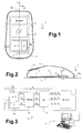
- Figure 1 is a partially sectioned schematic top plan view of a pointing device for a computer system that incorporates the present invention;
- Figure 2 is a partially sectioned side view of the device of Figure 1;
- Figure 3 is a simplified block diagram of the device of Figure 1;
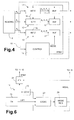
- Figure 4 is a more detailed block diagram regarding a part of the device illustrated in Figures 1-3;
- Figure 5 is a flowchart for a procedure implemented by the device according to the invention;
- Figure 6 is a block diagram of a part of the device of Figure 4, which implements the procedure of Figure 5; and
- Figure 7 shows a table regarding a detail of Figure 6.
- With reference to Figures 1-3, a pointing device of a computer system, in particular a
mouse 1, comprises ashell 2, aboard 3 housed within theshell 2, aninertial sensor 5, and amicrocontroller 6, which are in turn located on theboard 3 and form a displacement transducer of themouse 1. Themouse 1 is also equipped with aninterface 7 for connection with acomputer system 8 for communicating information and commands under the control of a user. In particular, theinterface 7 is of any standard type suitable for supporting communication with thecomputer system 8, for example, of a serial RS 232 or USB type. Alternatively, theinterface 7 enables a wireless connection through an optical (IR) or radiofrequency coupling, for example using Bluetooth technology. Themouse 1 is moreover equipped with one or more pushbuttons and/orwheels 4 for issuing commands to thecomputer system 8 under the control of a user. - The
inertial sensor 5 is connected to theboard 3 so as to be fixed with respect to theshell 2 and comprises a first, two-axes,accelerometer 5a and a second, single-axis,accelerometer 5b for detecting accelerations along three independent directions. Thefirst accelerometer 5a and thesecond accelerometer 5b are both of a micro-electro-mechanical type and are made with MEMS technology; for example, thefirst accelerometer 5a is of the type described in the European patent application No. EP-A-1365211, filed on May 21, 2002, and thesecond accelerometer 5b is of the type described in the European patent application No. EP-A-1253399, filed on April 27, 2001 or in US 5,955,668. Alternatively, theinertial sensor 5 can comprise three single-axis accelerometers, oriented in mutually perpendicular directions. - In greater detail, the
first accelerometer 5a has a first detection axis X and a second detection axis Y, which are mutually perpendicular and parallel to a sliding surface PS of the mouse 1 (generally a horizontal plane, as in Figure 2). The first detection axis X and the second detection axis Y are, moreover perpendicular and parallel, respectively, to a (vertical) longitudinal plane PL of symmetry of theshell 2. Thesecond accelerometer 5b has a third detection axis Z, which is not coplanar with and is preferably perpendicular to the plane defined by the first detection axis X and the second detection axis Y. The third axis Z is therefore substantially vertical when themouse 1 is resting on the surface of sliding PS. - The
inertial sensor 5 is connected to themicrocontroller 6 to provide a first analog acceleration signal SX, a second analog acceleration signal SY, and a third analog acceleration signal SZ (Figure 3) in response to the accelerations to which theshell 2 and theinertial sensor 5 are subjected along the first, second, and third axes of detection X, Y, Z, respectively. - The
microcontroller 6 is connected to thecomputer system 8 through the interface 7 (Figure 3) and supplies a first acceleration signal AX and a second acceleration signal AY, a first velocity signal VX and a second velocity signal VY, and a first displacement signal PX and a second displacement signal PY, all of which are of a numeric type and are calculated starting from the first and second analog acceleration signals SX, SY. In a pre-determined operating mode, which will be described in greater detail hereinafter, themicrocontroller 6 supplies also a third acceleration signal AZ, a third velocity signal VZ, and a third displacement signal PZ, which are of a numeric type and are calculated starting from the third analog acceleration signal SZ. In a way in itself known, thecomputer system 8 displays a cursor on a screen and determines its position on the basis of the signals received from themouse 1. - In greater detail, the
microcontroller 6 comprises areading unit 9 and aprocessing unit 10. Thereading unit 9 is connected to theinertial sensor 5 for receiving the first, second, and third analog acceleration signals SX, SY, SZ. In a way in itself known, moreover, thereading unit 9 supplies theinertial sensor 5 with control signals VFB and clock signals VCK necessary for reading; and theprocessing unit 10 with the first, second and third acceleration signals AX, AY, AZ, obtained from the analog-to-digital conversion of the first, second and third analog acceleration signals SX, SY, SZ, respectively. - As illustrated in the block diagram of Figure 3, the
processing unit 10 comprises afirst calculation line 11, asecond calculation line 12, athird calculation line 13, and acontrol stage 15. The first, second andthird calculation lines respective integration stage 16 and arespective buffer 17, which are cascade-connected. Theintegration stages 16 of the first, second andthird calculation lines reading unit 9, the first, second and third acceleration signals AX, AY, AZ, respectively, and integrate them a first time and a second time. In this way, theintegration stage 16 of thefirst calculation line 11 generates and supplies therespective buffer 17 with the first velocity signal VX and the first displacement signal PX. Theintegration stage 16 of thesecond calculation line 12 generates and supplies therespective buffer 17 with the second velocity signal VY and the second displacement signal PY. Finally, theintegration stage 16 of thethird calculation line 13 generates and supplies therespective buffer 17 with the third velocity signal VZ and the third displacement signal PZ. When thebuffers 17 are enabled by thecontrol stage 15, the values contained therein are made available to theinterface 7 for transmission to thecomputer system 8. - The
control stage 15 is connected to thereading unit 9 for receiving the third acceleration signal AZ, which is used for selecting one between a first operating mode, or 2D mode, and a second operating mode, or 3D mode, and, moreover, for disabling temporarily the first andsecond calculation lines mouse 1 is lifted off the sliding surface and the 2D mode is selected. For this purpose, thecontrol stage 15 generates a first control signal MODE and a second control signal STBY. The first control signal MODE has afirst value 2D, for the 2D mode, and asecond value 3D, for the 3D mode, and is supplied to thethird calculation line 13, which is selectively enabled in the 3D mode and disabled in the 2D mode. The second control signal STBY has a first value T, when themouse 1 is lifted off the sliding surface PS and the 2D mode is activated, and a second value F otherwise. The first andsecond calculation lines - In the 2D mode the
mouse 1 is configured to operate as a conventional mouse and sends only the first and second velocity signals VX, VY and the first and second displacement signals PX, PY to thecomputer system 8. Thesecond accelerometer 5b, instead, is used for monitoring lifting of themouse 1 from the sliding surface PS, but thethird calculation line 13 is disabled and does not supply information to thecomputer system 8. As soon as themouse 1 is lifted, the control stage detects a non-zero acceleration along the third detection axis Z using the third acceleration signal AZ. In this case, the second control signal STBY is set at the first value T, and the first andsecond calculation lines mouse 1 is again resting on the sliding surface PS. In this condition, which in effect represents a third operating mode, which can be selected transitorily, thecontrol stage 15 completely inhibits issuing to thecomputer system 8 of signals indicative of the motion of themouse 1 and hence prevents undesirable displacements of the cursor appearing on the display of thecomputer system 8 itself. - If the third acceleration signal AZ indicates that the
mouse 1 has remained lifted from the surface of sliding PS for longer than a pre-determined switching interval TCOM, thecontrol stage 15 selects the 3D mode, in which the first, second andthird calculation lines mouse 1 remains lifted from the surface of sliding PS. In this configuration, also the third acceleration signal AZ, coming from thesecond accelerometer 5b, is processed by thethird calculation line 13, and hence information regarding the motion of themouse 1 in three dimensions is sent to thecomputer system 8. - In practice, the
control stage 15 executes the procedure illustrated in the flowchart of Figure 5. At start-up of thecomputer system 8, themouse 1 is initialized (block 100) and set in the 2D mode (block 110). Then, in order to establish whether themouse 1 has been lifted, the absolute value of the third acceleration signal AZ is compared with a threshold TH (block 120). The threshold TH can be pre-determined and is preferably programmable in a set-up step of themouse 1. Alternatively, the threshold TH is continuously recalculated when themouse 1 is in 2D mode, to take into account the effect of the force of gravity on thesecond accelerometer 5b, which can vary according to the inclination of the sliding surface PS. In this case, the fact that the contribution of the force of gravity is substantially constant if themouse 1 moves along a plane, such as the sliding surface PS, is exploited, and such a contribution can be estimated by filtering the third acceleration signal AZ with a low-pass filter, which extracts the low-frequency spectral components. In both cases, the threshold TH is determined so as to be exceeded even when themouse 1 is subjected to minimal accelerations along the third axis Z, such as the accelerations caused by involuntary movements of the user when themouse 1 is kept lifted up. It should be noted that the effects of involuntary movements can be suppressed to prevent undesirable displacements of the cursor when themouse 1 is in the 3D mode. For this purpose, for example, it is possible to envisage appropriate algorithms of integration for theintegrators 16, which are selectively activatable when the first control signal MODE has thesecond value 3D. - If the absolute value of the third acceleration signal AZ is lower than the threshold TH (output NO from block 120), the second control signal is set at the second value F (block 130), and the test of
block 120 is carried out again. - If the absolute value of the third acceleration signal AZ is not lower than the threshold TH (output YES from block 120), the
control stage 15 checks (block 140) whether themouse 1 has remained lifted up for a time longer than the switching interval TCOM, i.e., whether, in said interval, the threshold TH has been exceeded substantially without any interruption. If the switching interval TCOM has not yet elapsed (output NO from block 140), the second control signal STBY is set at the first value T for temporary disabling of the first andsecond calculation lines 11, 12 (block 150). If themouse 1 remains lifted until the end of the switching interval TCOM without resting on the surface of sliding PS or on a different surface, herein not illustrated (output YES from block 140), thecontrol stage 15 selects the 3D mode, by setting the first control signal MODE at thesecond value 3D (block 160). - The 3D mode is maintained as long as the absolute value of the third acceleration signal AZ remains higher than the threshold TH (block 170 and output YES from block 170). Possibly, a further threshold can be used, different from the threshold TH. When the
mouse 1 is put down, the third acceleration signal AZ drops below the threshold TH (output NO from block 170). In this case, thecontrol stage 15 selects the 2D mode (block 130), and the test of theblock 120 is carried out again. - An example of the
control stage 15 is illustrated in Figure 6. In particular, thecontrol stage 15 comprises a threshold-discrimination module 20, agate 21, acounter 22, alogic module 23, and amode register 24. - The threshold-
discrimination module 20 receives the third acceleration signal AZ from thereading unit 9 and uses it to establish whether themouse 1 is resting on a surface or has been lifted (in the example described, it compares the third acceleration signal AZ with the threshold TH). If themouse 1 has been lifted, the threshold-discrimination module 20 requests deactivation of the first andsecond calculation lines gate 21 and activates thecounter 22. In particular, the threshold-discrimination module 20 assigns, to a third control signal LIFT, a pre-set value, which indicates that themouse 1 has been lifted (in this case, following upon overstepping of the threshold TH). Thegate 21, which supplies at output the second control signal STBY, is controlled by the first control signal MODE, the value of which is stored in themode register 24. In particular, thegate 21 enables the request for deactivation of the first andsecond calculation lines first value 2D of the first control signal MODE is contained in themode register 24. In this case, the first value T is assigned to the second control signal STBY. - The
logic module 23 controls themode register 24 so as to keep the value of the first control signal MODE updated and to select the 2D mode or the 3D mode in accordance with the procedure described above with reference to Figure 5. For this purpose, thelogic module 23 receives the current value of the first control signal MODE from themode register 24, the third control signal LIFT from the threshold-discrimination module 20, and a counting value contained in thecounter 22. In the example described, thelogic module 23 operates on the basis of the table of Figure 7, where the new value to be assigned and the current value of the first control signal MODE are indicated in the columns "MODEK+1" and "MODEK", respectively. Furthermore, in the column "LIFT", the values T' and F' indicate that themouse 1 has been lifted and put down, respectively; and in the column "TCOM", the values T" and F" indicate that, on the basis of the counting value contained in thecounter 22, themouse 1 has remained continuously lifted for a time longer than or shorter than, respectively, the switching interval TCOM. - Advantageously, the invention enables automatic detection of lifting of the pointing device and, consequently, selection of an appropriate operating mode. In particular, the device can be used both as a two-dimensional pointing peripheral and as a three-dimensional pointing peripheral. Furthermore, production of signals is inhibited during the brief steps of lifting that are normally necessary when the device operates in two-dimensional mode. Also the selection of the mode of operation is automatic, and the user is not required to perform any special manoeuvres.
- Finally, it is evident that modifications and variations can be made to the pointing device and to the method described herein, without departing from the scope of the present invention, as defined in the annexed claims.
- In particular, the invention could be incorporated in a device other than a mouse, such as for example a pen or a cellphone. As regards detection of the motion along the first and second axes X, Y, the pointing device can be equipped with a transducer of the type conventionally used in a mouse (for example, a transducer with a ball combined with rollers provided with angular-position sensors or an optical transducer). In this case, just one single-axis MEMS sensor is used for detection of the motion along the third axis Z.
- Also the procedure of selection of the operating mode could differ from the one described herein. In particular, different criteria could be used to decide whether the pointing device has been lifted or is resting on a surface. For example, differentiated thresholds can be used, instead of just one threshold. Furthermore, in addition to acceleration, it is also possible to consider the velocity along the third axis Z. Also the scheme of the control stage would be modified accordingly.
Claims (21)
- A pointing device for a computer system comprising:a first movement sensor (5a), for detecting movements of said device (1) along a first axis (X) and a second axis (Y), which are not aligned;a second movement sensor (5b), for detecting movements of said device (1) along a third axis (Z) not aligned to said first and second axes (X, Y); andprocessing means (6) associated to said first and second movement sensors (5a, 5b) for producing a plurality of movement signals (AX, AY, AZ, VX, VY, VZ, PX, PY, PZ) indicating the movement of said device (1) along said first, second andthird axes (X, Y, Z);characterized in that said processing means (6) comprise a control stage (15), for controlling a mode of production of said movement signals (AX, AY, AZ, VX, VY, VZ, PX, PY, PZ) on the basis of a response (SZ, AZ) of said second movement sensor (5b).
- The device according to claim 1, characterized in that said processing means (6) comprise a first calculation line (11) and a second calculation line (12), associated to said first movement sensor (5a) for producing a first set (VX, VY, PX, PY) of said movement signals (AX, AY, AZ, VX, VY, VZ, PX, PY, PZ), indicative of the movement of said device along said first and second axes (X, Y) and in that said control stage (15) comprises enabling means (20, 21) for selectively enabling and disabling said first and second calculation lines (11, 12) on the basis of said response (SZ, AZ) of said second movement sensor (5b).
- The device according to claim 2, characterized in that said enabling means (20, 21) are configured for temporarily disabling said first and second calculation lines (11, 12) in response to the detection of an acceleration of said device(1) along said third axis (Z).
- The device according to claim 2 or claim 3, characterized in that said enabling means comprise a threshold-discrimination module (20), for comparing said response (SZ, AZ) of said second movement sensor (5b) with a threshold (TH) and generating a control signal (STBY) on the basis of said response (SZ, AZ) and of said threshold (TH).
- The device according to any one of the preceding claims,
characterized in that said control stage comprises selection means (22, 23, 24) for alternatively selecting a first operating mode (2D) and a second operating mode (3D) of said device on the basis of said response (SZ, AZ), said threshold (TH), and a pre-determined time interval (TCOM). - The device according to claim 5, characterized in that, when said first operating mode (2D) is selected, said movement signals (AX, AY, AZ, VX, VY, VZ, PX, PY, PZ) are produced on the basis of a response (SX, SY, AX, AY) of said first movement sensor (5a) and, when said second operating mode (3D) is selected, said movement signals (AX, AY, AZ, VX, VY, VZ, PX, PY, PZ) are produced on the basis of said response (SX, SY, AX, AY) of said first movement sensor (5a) and of said response (SZ, AZ) of said second movement sensor (5b).
- The device according to claim 5 or claim 6, characterized in that said processing means (6) comprise a third calculation line (13), associated to said second movement sensor (5b) for producing a second set (VZ, PZ) of said movement signals (AX, AY, AZ, VX, VY, VZ, PX, PY, PZ), indicative of the movement of said device along said third axis (Z), and in that said selection means (22, 23, 24) are configured for selectively enabling said third calculation line (13), when said second operating mode (3D) is selected, and disabling said third calculation line (13), when said first operating mode (2D) is selected.
- The device according to any one of the preceding claims,
characterized in that said third axis (Z) is substantially vertical. - The device according to any one of the preceding claims,
characterized in that said first movement sensor (5a) comprises a first MEMS accelerometer. - The device according to any one of the preceding claims,
characterized in that said second movement sensor (5b) comprises a second MEMS accelerometer. - A method for controlling a pointing device (1) for a computer system, comprising the steps of:detecting movements of said device (1) along a first axis (X) and a second axis (Y);detecting movements of said device (1) along a third axis (Z) not coplanar with said first and second axes (X, Y);producing a plurality of movement signals (AX, AY, AZ, VX, VY, VZ, PX, PY, PZ) indicative of the movement of said device (1) along said first, second and third axes (X, Y, Z);characterized in that it comprises the step of controlling a mode of production of said movement signals (AX, AY, AZ, VX, VY, VZ, PX, PY, PZ) in response to movements of said device (1) along said third axis (Z).
- The device according to claim 11, characterized in that said step of controlling comprises selectively enabling (130, 150) and inhibiting (160) production of said movement signals (AX, AY, AZ, VX, VY, VZ, PX, PY, PZ) in response to movements (SZ, AZ) of said device (1) along said third axis (Z).
- The method according to claim 12, characterized in that said step of controlling comprises disabling temporarily the production of said movement signals (AX, AY, AZ, VX, VY, VZ, PX, PY, PZ) in response to the detection of an acceleration (SZ, AZ) of said device (1) along said third axis (Z).
- The method according to any one of claims 11-13,
characterized in that said step of controlling comprises detecting lifting of said device (1) in response to movements of said device (1) along said third axis (Z). - The method according to any one of the preceding claims 11-14, characterized in that said step of controlling comprises alternatively selecting a first operating mode (2D) and a second operating mode (3D) of said device in response to movements (SZ, AZ) of said device (1) along said third axis (Z) and on the basis of a pre-determined time interval (TCOM).
- The method according to claim 15, characterized in that, when said first operating mode (2D) is selected, said movement signals (AX, AY, AZ, VX, VY, VZ, PX, PY, PZ) are produced on the basis of movements of said device (1) along said first and second axes (X, Y), and, when said second operating mode (3D) is selected, said movement signals (AX, AY, AZ, VX, VY, VZ, PX, PY, PZ) are produced on the basis of movements of said device(1) along said first, second and third axes (X, Y, Z).
- The method according to claim 15 or claim 16,
characterized in that said step of controlling comprises producing said movement signals (AX, AY, AZ, VX, VY, VZ, PX, PY, PZ) on the basis of the movement of said device (1) along said first and second axes (X, Y), when said first operating mode (2D) is selected, and producing said movement signals (AX, AY, AZ, VX, VY, VZ, PX, PY, PZ) on the basis of the movement of said device (1) along said first, second and third axes (X, Y, Z), when said second operating mode (3D) is selected. - The method according to any one of claims 15-17,
characterized in that said second operating mode (3D) is selected after an acceleration along said third axis (Z) has been detected without interruption for a time longer than said pre-set time interval (TCOM). - The method according to any one of claims 11-18,
characterized in that said third axis (Z) is substantially vertical. - The method according to any one of claims 11-19,
characterized in that said step of detecting movements of said device (1) along a first axis (X) and a second axis (Y) comprises using a first MEMS accelerometer (5a). - The method according to any one of claims 11-20,
characterized in that said step of detecting movements of said device (1) along a third axis (Z) comprises using a second MEMS accelerometer (5b).
Priority Applications (4)
| Application Number | Priority Date | Filing Date | Title |
|---|---|---|---|
| EP04425959A EP1677178A1 (en) | 2004-12-29 | 2004-12-29 | Pointing device for a computer system with automatic detection of lifting, and relative control method |
| PCT/EP2005/056917 WO2006069932A1 (en) | 2004-12-29 | 2005-12-19 | Pointing device for a computer system with automatic detection of lifting, and relative control method |
| CN2005800488565A CN101142545B (en) | 2004-12-29 | 2005-12-19 | Pointing device for a computer system with automatic detection of lifting, and relative control method |
| US11/771,957 US7924267B2 (en) | 2004-12-29 | 2007-06-29 | Pointing device for a computer system with automatic detection of lifting, and relative control method |
Applications Claiming Priority (1)
| Application Number | Priority Date | Filing Date | Title |
|---|---|---|---|
| EP04425959A EP1677178A1 (en) | 2004-12-29 | 2004-12-29 | Pointing device for a computer system with automatic detection of lifting, and relative control method |
Publications (1)
| Publication Number | Publication Date |
|---|---|
| EP1677178A1 true EP1677178A1 (en) | 2006-07-05 |
Family
ID=34932967
Family Applications (1)
| Application Number | Title | Priority Date | Filing Date |
|---|---|---|---|
| EP04425959A Withdrawn EP1677178A1 (en) | 2004-12-29 | 2004-12-29 | Pointing device for a computer system with automatic detection of lifting, and relative control method |
Country Status (4)
| Country | Link |
|---|---|
| US (1) | US7924267B2 (en) |
| EP (1) | EP1677178A1 (en) |
| CN (1) | CN101142545B (en) |
| WO (1) | WO2006069932A1 (en) |
Cited By (2)
| Publication number | Priority date | Publication date | Assignee | Title |
|---|---|---|---|---|
| US7817134B2 (en) * | 2006-11-29 | 2010-10-19 | Industrial Technology Research Institute | Pointing device |
| WO2018056896A1 (en) * | 2016-09-23 | 2018-03-29 | Razer (Asia-Pacific) Pte. Ltd. | Input devices, methods for providing an input to a computing system and computer readable media |
Families Citing this family (29)
| Publication number | Priority date | Publication date | Assignee | Title |
|---|---|---|---|---|
| US20100156783A1 (en) * | 2001-07-06 | 2010-06-24 | Bajramovic Mark | Wearable data input device |
| US7688307B1 (en) * | 2006-01-24 | 2010-03-30 | Zilog, Inc. | Determining the distance an object has moved using an accelerometer |
| US7934423B2 (en) | 2007-12-10 | 2011-05-03 | Invensense, Inc. | Vertically integrated 3-axis MEMS angular accelerometer with integrated electronics |
| US8952832B2 (en) | 2008-01-18 | 2015-02-10 | Invensense, Inc. | Interfacing application programs and motion sensors of a device |
| US8250921B2 (en) * | 2007-07-06 | 2012-08-28 | Invensense, Inc. | Integrated motion processing unit (MPU) with MEMS inertial sensing and embedded digital electronics |
| US8462109B2 (en) | 2007-01-05 | 2013-06-11 | Invensense, Inc. | Controlling and accessing content using motion processing on mobile devices |
| JP2008282400A (en) * | 2007-05-08 | 2008-11-20 | Lin Ming-Yen | Three-dimensional mouse device |
| TW200907764A (en) * | 2007-08-01 | 2009-02-16 | Unique Instr Co Ltd | Three-dimensional virtual input and simulation apparatus |
| TW200923719A (en) * | 2007-11-19 | 2009-06-01 | Asustek Comp Inc | Input apparatus and optical mouse for computer and operation method thereof |
| US8130200B2 (en) * | 2008-01-14 | 2012-03-06 | Benjamin Slotznick | Combination thumb keyboard and mouse |
| TW200951762A (en) * | 2008-06-03 | 2009-12-16 | Asustek Comp Inc | Input device and operation method of computer |
| US20100060567A1 (en) * | 2008-09-05 | 2010-03-11 | Microsoft Corporation | Controlling device operation relative to a surface |
| US8552980B2 (en) * | 2009-04-30 | 2013-10-08 | Gregory A. Shaver | Computer input devices and associated computing devices, software, and methods |
| KR101830870B1 (en) * | 2011-06-22 | 2018-02-21 | 엘지전자 주식회사 | A Method for displaying a scan image, display apparatus thereof and a method for acquring a information for scan image, input apparatus thereof |
| TWI552026B (en) * | 2012-06-07 | 2016-10-01 | 原相科技股份有限公司 | Hand-held pointing device |
| US10067576B2 (en) | 2013-02-19 | 2018-09-04 | Pixart Imaging Inc. | Handheld pointer device and tilt angle adjustment method thereof |
| US9804689B2 (en) | 2013-02-19 | 2017-10-31 | Pixart Imaging Inc. | Handheld pointer device and pointer positioning method thereof |
| HRP20220503T1 (en) | 2013-03-15 | 2022-05-27 | Canary Medical Inc. | Devices, systems and methods for monitoring hip replacements |
| PT3013283T (en) | 2013-06-23 | 2021-03-11 | Canary Medical Inc | Devices, systems and methods for monitoring knee replacements |
| US11596347B2 (en) | 2014-06-25 | 2023-03-07 | Canary Medical Switzerland Ag | Devices, systems and methods for using and monitoring orthopedic hardware |
| WO2015200720A2 (en) | 2014-06-25 | 2015-12-30 | Hunter William L | Devices, systems and methods for using and monitoring spinal implants |
| US10874496B2 (en) | 2014-06-25 | 2020-12-29 | Canary Medical Inc. | Devices, systems and methods for using and monitoring implants |
| US20180125365A1 (en) | 2014-09-17 | 2018-05-10 | Canary Medical Inc. | Devices, systems and methods for using and monitoring medical devices |
| MX2018011544A (en) | 2016-03-23 | 2019-06-24 | Canary Medical Inc | Implantable reporting processor for an alert implant. |
| US11191479B2 (en) | 2016-03-23 | 2021-12-07 | Canary Medical Inc. | Implantable reporting processor for an alert implant |
| US11409375B2 (en) * | 2016-11-11 | 2022-08-09 | Pixart Imaging Inc. | Method and apparatus for adjusting optical setting of optical input device and related optical input device |
| CN107688348B (en) * | 2017-08-10 | 2020-10-20 | 中国科学院半导体研究所 | Wireless man-machine interaction equipment and method for realizing pointing control function |
| WO2022076686A1 (en) | 2020-10-07 | 2022-04-14 | Canary Medical Switzerland Ag | Providing medical devices with sensing functionality |
| WO2023278775A1 (en) | 2021-07-01 | 2023-01-05 | Canary Medical Switzerland Ag | Systems and methods for processing and analyzing kinematic data from intelligent kinematic devices |
Citations (7)
| Publication number | Priority date | Publication date | Assignee | Title |
|---|---|---|---|---|
| US4787051A (en) * | 1986-05-16 | 1988-11-22 | Tektronix, Inc. | Inertial mouse system |
| US4839838A (en) * | 1987-03-30 | 1989-06-13 | Labiche Mitchell | Spatial input apparatus |
| US5181181A (en) * | 1990-09-27 | 1993-01-19 | Triton Technologies, Inc. | Computer apparatus input device for three-dimensional information |
| JPH10171596A (en) * | 1996-12-06 | 1998-06-26 | Oki Electric Ind Co Ltd | Mouse |
| JP2001142636A (en) * | 1999-11-11 | 2001-05-25 | Seiko Epson Corp | Mouse and computer |
| JP2004151927A (en) * | 2002-10-30 | 2004-05-27 | Mitsumi Electric Co Ltd | Mouse input device |
| US20040135825A1 (en) * | 2003-01-14 | 2004-07-15 | Brosnan Michael J. | Apparatus for controlling a screen pointer that distinguishes between ambient light and light from its light source |
Family Cites Families (13)
| Publication number | Priority date | Publication date | Assignee | Title |
|---|---|---|---|---|
| US5355146A (en) * | 1990-03-05 | 1994-10-11 | Bmc Micro-Industries Ltd. | Multi-directional hand scanner and mouse |
| US5835077A (en) * | 1995-01-13 | 1998-11-10 | Remec, Inc., | Computer control device |
| NO300943B1 (en) * | 1995-04-03 | 1997-08-18 | Steinar Pedersen | Tools for positioning and controlling objects in two or three dimensions |
| US5703623A (en) * | 1996-01-24 | 1997-12-30 | Hall; Malcolm G. | Smart orientation sensing circuit for remote control |
| US5825350A (en) * | 1996-03-13 | 1998-10-20 | Gyration, Inc. | Electronic pointing apparatus and method |
| US5955668A (en) * | 1997-01-28 | 1999-09-21 | Irvine Sensors Corporation | Multi-element micro gyro |
| DE60120921T2 (en) | 2001-04-27 | 2007-02-01 | Stmicroelectronics S.R.L., Agrate Brianza | Integrated gyro made of semiconductor material |
| US6784870B2 (en) * | 2001-05-14 | 2004-08-31 | Hewlett-Packard Development Company, L.P. | Portable computer system including detachable peripheral device and combined mouse/joystick for use with same |
| US20030142065A1 (en) * | 2002-01-28 | 2003-07-31 | Kourosh Pahlavan | Ring pointer device with inertial sensors |
| US20030214484A1 (en) * | 2002-05-20 | 2003-11-20 | Haywood Chad Christian | Convertible mouse |
| DE60221103T2 (en) | 2002-05-21 | 2008-04-03 | Stmicroelectronics S.R.L., Agrate Brianza | Integrated gyroscope made of semiconductor material with at least one sensitive axis in the sensor plane |
| US20040104891A1 (en) * | 2002-11-25 | 2004-06-03 | Frank Sacca | Intertial pointer for electronic displays |
| US8842070B2 (en) * | 2004-03-17 | 2014-09-23 | Intel Corporation | Integrated tracking for on screen navigation with small hand held devices |
-
2004
- 2004-12-29 EP EP04425959A patent/EP1677178A1/en not_active Withdrawn
-
2005
- 2005-12-19 CN CN2005800488565A patent/CN101142545B/en active Active
- 2005-12-19 WO PCT/EP2005/056917 patent/WO2006069932A1/en active Application Filing
-
2007
- 2007-06-29 US US11/771,957 patent/US7924267B2/en active Active
Patent Citations (7)
| Publication number | Priority date | Publication date | Assignee | Title |
|---|---|---|---|---|
| US4787051A (en) * | 1986-05-16 | 1988-11-22 | Tektronix, Inc. | Inertial mouse system |
| US4839838A (en) * | 1987-03-30 | 1989-06-13 | Labiche Mitchell | Spatial input apparatus |
| US5181181A (en) * | 1990-09-27 | 1993-01-19 | Triton Technologies, Inc. | Computer apparatus input device for three-dimensional information |
| JPH10171596A (en) * | 1996-12-06 | 1998-06-26 | Oki Electric Ind Co Ltd | Mouse |
| JP2001142636A (en) * | 1999-11-11 | 2001-05-25 | Seiko Epson Corp | Mouse and computer |
| JP2004151927A (en) * | 2002-10-30 | 2004-05-27 | Mitsumi Electric Co Ltd | Mouse input device |
| US20040135825A1 (en) * | 2003-01-14 | 2004-07-15 | Brosnan Michael J. | Apparatus for controlling a screen pointer that distinguishes between ambient light and light from its light source |
Non-Patent Citations (3)
| Title |
|---|
| PATENT ABSTRACTS OF JAPAN vol. 1998, no. 11 30 September 1998 (1998-09-30) * |
| PATENT ABSTRACTS OF JAPAN vol. 2000, no. 22 9 March 2001 (2001-03-09) * |
| PATENT ABSTRACTS OF JAPAN vol. 2003, no. 12 5 December 2003 (2003-12-05) * |
Cited By (3)
| Publication number | Priority date | Publication date | Assignee | Title |
|---|---|---|---|---|
| US7817134B2 (en) * | 2006-11-29 | 2010-10-19 | Industrial Technology Research Institute | Pointing device |
| WO2018056896A1 (en) * | 2016-09-23 | 2018-03-29 | Razer (Asia-Pacific) Pte. Ltd. | Input devices, methods for providing an input to a computing system and computer readable media |
| US11442558B2 (en) | 2016-09-23 | 2022-09-13 | Razer (Asia-Pacific) Pte. Ltd. | Input devices, methods for providing an input to a computing system and computer readable media |
Also Published As
| Publication number | Publication date |
|---|---|
| US20080122788A1 (en) | 2008-05-29 |
| WO2006069932A8 (en) | 2007-06-07 |
| CN101142545A (en) | 2008-03-12 |
| CN101142545B (en) | 2012-11-14 |
| WO2006069932A1 (en) | 2006-07-06 |
| US7924267B2 (en) | 2011-04-12 |
Similar Documents
| Publication | Publication Date | Title |
|---|---|---|
| US7924267B2 (en) | Pointing device for a computer system with automatic detection of lifting, and relative control method | |
| US8798956B2 (en) | Method and apparatus for surface sensing input device | |
| EP2768589B1 (en) | Multi-sensored control stick for enhanced input sensitivity and functionality | |
| US10042438B2 (en) | Systems and methods for text entry | |
| JP4713540B2 (en) | Inertial sensing method and system | |
| JP5161527B2 (en) | Interactive pointing device | |
| CN101598980A (en) | Input equipment, opertaing device, control system and control method | |
| CN102033689A (en) | Mobile terminal and method for displaying information on mobile terminal | |
| US20130024065A1 (en) | Autonomous Electronic Device and Method of Controlling Motion of the Autonomous Electronic Device Thereof | |
| US20110260974A1 (en) | Manual pointing device for a computer system with inertial click event detection and corresponding click event detection method | |
| US11445058B2 (en) | Electronic device and method for controlling display operation thereof | |
| KR100528348B1 (en) | Input device for multi-layer on screen display and method for generating input signal therefor | |
| KR101714628B1 (en) | Apparatus and method for user authentication using a movement information | |
| US20100328212A1 (en) | system and method for providing roll compensation | |
| CN103425405B (en) | Body-sensing remote control unit mode switching method | |
| US20130099903A1 (en) | Remote controller | |
| KR20210018992A (en) | Control and processing unit for touch screen, system including same and method of use | |
| CN109782930B (en) | Control method of pressure speed mouse | |
| US7710392B2 (en) | Pointing device for a computer system with automatic detection of the state of motion, and a relative control method | |
| KR100953861B1 (en) | End point detection method, mouse device applying the end point detection method and operating method using the mouse device | |
| EP2631742A2 (en) | Electronic device with a remote control | |
| WO2012037565A1 (en) | Remote control functionality including information from motion sensors | |
| CN103793124A (en) | Automatic locking device and method of double-sided remote controller | |
| CN110553647B (en) | Timing method | |
| CN101539814B (en) | Multifunctional device and method therefor |
Legal Events
| Date | Code | Title | Description |
|---|---|---|---|
| PUAI | Public reference made under article 153(3) epc to a published international application that has entered the european phase |
Free format text: ORIGINAL CODE: 0009012 |
|
| AK | Designated contracting states |
Kind code of ref document: A1 Designated state(s): AT BE BG CH CY CZ DE DK EE ES FI FR GB GR HU IE IS IT LI LT LU MC NL PL PT RO SE SI SK TR |
|
| AX | Request for extension of the european patent |
Extension state: AL BA HR LV MK YU |
|
| 17P | Request for examination filed |
Effective date: 20070103 |
|
| AKX | Designation fees paid |
Designated state(s): DE FR GB IT |
|
| 17Q | First examination report despatched |
Effective date: 20070316 |
|
| RAP1 | Party data changed (applicant data changed or rights of an application transferred) |
Owner name: STMICROELECTRONICS SRL |
|
| RAP1 | Party data changed (applicant data changed or rights of an application transferred) |
Owner name: STMICROELECTRONICS SRL |
|
| STAA | Information on the status of an ep patent application or granted ep patent |
Free format text: STATUS: THE APPLICATION IS DEEMED TO BE WITHDRAWN |
|
| 18D | Application deemed to be withdrawn |
Effective date: 20141014 |