EP1670688B1 - Ergonomischer wegwerf-becher mit verbesserter formfestigkeit - Google Patents
Ergonomischer wegwerf-becher mit verbesserter formfestigkeit Download PDFInfo
- Publication number
- EP1670688B1 EP1670688B1 EP04749453A EP04749453A EP1670688B1 EP 1670688 B1 EP1670688 B1 EP 1670688B1 EP 04749453 A EP04749453 A EP 04749453A EP 04749453 A EP04749453 A EP 04749453A EP 1670688 B1 EP1670688 B1 EP 1670688B1
- Authority
- EP
- European Patent Office
- Prior art keywords
- container
- sidewall
- base
- annular shoulder
- cup
- Prior art date
- Legal status (The legal status is an assumption and is not a legal conclusion. Google has not performed a legal analysis and makes no representation as to the accuracy of the status listed.)
- Expired - Lifetime
Links
- 230000000087 stabilizing effect Effects 0.000 claims description 3
- 230000002708 enhancing effect Effects 0.000 claims 1
- 238000004519 manufacturing process Methods 0.000 description 14
- 239000000463 material Substances 0.000 description 10
- 238000010276 construction Methods 0.000 description 9
- 230000008901 benefit Effects 0.000 description 8
- 238000000034 method Methods 0.000 description 8
- 239000004033 plastic Substances 0.000 description 6
- 229920003023 plastic Polymers 0.000 description 6
- 238000012360 testing method Methods 0.000 description 6
- 238000013461 design Methods 0.000 description 5
- 230000035622 drinking Effects 0.000 description 5
- 238000003856 thermoforming Methods 0.000 description 5
- 238000004458 analytical method Methods 0.000 description 4
- 230000009286 beneficial effect Effects 0.000 description 4
- 230000008859 change Effects 0.000 description 4
- 230000006872 improvement Effects 0.000 description 4
- 230000007704 transition Effects 0.000 description 4
- 239000012530 fluid Substances 0.000 description 3
- 239000000523 sample Substances 0.000 description 3
- 235000020965 cold beverage Nutrition 0.000 description 2
- 230000006835 compression Effects 0.000 description 2
- 238000007906 compression Methods 0.000 description 2
- 230000005494 condensation Effects 0.000 description 2
- 238000009833 condensation Methods 0.000 description 2
- 230000001419 dependent effect Effects 0.000 description 2
- 239000006261 foam material Substances 0.000 description 2
- 230000000670 limiting effect Effects 0.000 description 2
- -1 polyethylene Polymers 0.000 description 2
- 230000002441 reversible effect Effects 0.000 description 2
- 239000004698 Polyethylene Substances 0.000 description 1
- 239000004743 Polypropylene Substances 0.000 description 1
- 239000004793 Polystyrene Substances 0.000 description 1
- 229920006328 Styrofoam Polymers 0.000 description 1
- 230000015572 biosynthetic process Effects 0.000 description 1
- 230000000295 complement effect Effects 0.000 description 1
- 238000005336 cracking Methods 0.000 description 1
- 230000007423 decrease Effects 0.000 description 1
- 230000003247 decreasing effect Effects 0.000 description 1
- 230000009977 dual effect Effects 0.000 description 1
- 230000000694 effects Effects 0.000 description 1
- 238000005516 engineering process Methods 0.000 description 1
- 239000006260 foam Substances 0.000 description 1
- 239000004088 foaming agent Substances 0.000 description 1
- 238000005755 formation reaction Methods 0.000 description 1
- 239000011521 glass Substances 0.000 description 1
- 238000003475 lamination Methods 0.000 description 1
- 238000012986 modification Methods 0.000 description 1
- 230000004048 modification Effects 0.000 description 1
- 230000036961 partial effect Effects 0.000 description 1
- 239000002985 plastic film Substances 0.000 description 1
- 229920000728 polyester Polymers 0.000 description 1
- 229920000573 polyethylene Polymers 0.000 description 1
- 229920000642 polymer Polymers 0.000 description 1
- 229920001155 polypropylene Polymers 0.000 description 1
- 229920002223 polystyrene Polymers 0.000 description 1
- 230000008569 process Effects 0.000 description 1
- 238000012545 processing Methods 0.000 description 1
- 230000004044 response Effects 0.000 description 1
- 230000000284 resting effect Effects 0.000 description 1
- 238000006748 scratching Methods 0.000 description 1
- 230000002393 scratching effect Effects 0.000 description 1
- 239000008261 styrofoam Substances 0.000 description 1
- 229920001169 thermoplastic Polymers 0.000 description 1
- 239000012815 thermoplastic material Substances 0.000 description 1
- 239000004416 thermosoftening plastic Substances 0.000 description 1
- 238000012546 transfer Methods 0.000 description 1
Images


Classifications
-
- B—PERFORMING OPERATIONS; TRANSPORTING
- B65—CONVEYING; PACKING; STORING; HANDLING THIN OR FILAMENTARY MATERIAL
- B65D—CONTAINERS FOR STORAGE OR TRANSPORT OF ARTICLES OR MATERIALS, e.g. BAGS, BARRELS, BOTTLES, BOXES, CANS, CARTONS, CRATES, DRUMS, JARS, TANKS, HOPPERS, FORWARDING CONTAINERS; ACCESSORIES, CLOSURES, OR FITTINGS THEREFOR; PACKAGING ELEMENTS; PACKAGES
- B65D1/00—Containers having bodies formed in one piece, e.g. by casting metallic material, by moulding plastics, by blowing vitreous material, by throwing ceramic material, by moulding pulped fibrous material, by deep-drawing operations performed on sheet material
- B65D1/22—Boxes or like containers with side walls of substantial depth for enclosing contents
- B65D1/26—Thin-walled containers, e.g. formed by deep-drawing operations
- B65D1/265—Drinking cups
-
- B—PERFORMING OPERATIONS; TRANSPORTING
- B65—CONVEYING; PACKING; STORING; HANDLING THIN OR FILAMENTARY MATERIAL
- B65D—CONTAINERS FOR STORAGE OR TRANSPORT OF ARTICLES OR MATERIALS, e.g. BAGS, BARRELS, BOTTLES, BOXES, CANS, CARTONS, CRATES, DRUMS, JARS, TANKS, HOPPERS, FORWARDING CONTAINERS; ACCESSORIES, CLOSURES, OR FITTINGS THEREFOR; PACKAGING ELEMENTS; PACKAGES
- B65D1/00—Containers having bodies formed in one piece, e.g. by casting metallic material, by moulding plastics, by blowing vitreous material, by throwing ceramic material, by moulding pulped fibrous material, by deep-drawing operations performed on sheet material
- B65D1/40—Details of walls
- B65D1/42—Reinforcing or strengthening parts or members
- B65D1/46—Local reinforcements, e.g. adjacent closures
Definitions
- the present invention relates generally to the field of thermoformed nestable containers, specifically, the construction of a container such as a cup or cup-like article that is capable of being nested with a similar article. More specifically, the present invention, in its preferred embodiment, relates to improved grippability and structural integrity in thermoformed nestable containers.
- thermoformed plastic molded containers have been a replacement to the less environmentally concerned foam articles in the industry.
- the use of nestable thermoformed containers has been on the rise.
- Thermoplastic materials are particularly advantageous for manufacturers as the materials do not require expensive foaming agents and need no surface lamination - each of which is a feature resulting in fewer stages of the manufacturing process. Moreover, for consumers, containers constructed from these materials are generally more durable than paper containers, are usually of a single-piece construction, and are inexpensive and recyclable.
- Thermoforming begins with a thin sheet or web of material such as polyethylene, polypropylene, polyester, or polystyrene having a thickness within a range of from approximately 8 mils to 100 mils, depending on the size of the container to be manufactured. Cups and similar articles are typically made from plastic sheet having a pre-thermoforming thickness from approximately 30 to 60 mils, but the finished articles may be thinner after thermoforming.
- the sheet or web is heated to a temperature suitable for thermoforming - in a range from approximately 110 °C to about 200 °C for the above-mentioned materials - and is thereafter fed into a conventional forming machine in which the process proceeds under applied positive and/or negative air pressure conditions.
- a mold cavity is used to impart a particular formational construction into the thin-walled container as the plastic material is drawn into the mold using vacuum pressure on one side of the article and/or a positive pressure on the opposite surface of the material.
- the formational construction of the container may be decorative, but generally has a particular utility - e.g., texturing for grasping and formations for nestability in addition to other utilities.
- the processing period for a normal thermoforming operation is typically between 1 and 20 seconds.
- thermoformed plastic nestable containers Another problem with thermoformed plastic nestable containers is structural integrity. Sidewalls of thin-walled thermoformed containers often bend and deflect inward easily when grasped by a user. A deflection of this sort may constrict the volume of the container causing unpleasant fluid overflows. Additionally, deflection of the sidewall can make the container more difficult to grip, as well as potentially leading to cracking.
- One solution to the identified problem is to provide thicker material constructions, but this increases production costs. Additionally, thicker constructions tend to increase the stack height among nested containers. These respective phenomena limit the number of containers that may be nested in a confined area and can prevent the nested containers from being easily separated.
- the present invention solves these two problems primarily by creating arcuately formed longitudinal recesses in the sidewall. These recesses both provide an ergonomic and effective gripping surface and increase structural integrity. However, the recesses can create problems with proper nesting of the containers, which tend to telescope because of their lack of complete rotational symmetry. Thus, a need further exists for a means to ensure proper nesting of containers having recesses in their sidewalls.
- British Patent No. 1,461,394 discloses a cup provided with vertically extending circumferential stacking means.
- the lower external section of the stacking means includes a plurality of circumferentially distributed, triangular-shaped abutment surfaces which diverge upwardly in pairs from bottom radial lines of intersection.
- the upper internal section of the stacking means includes a plurality of pairs of generally trapezoidal internal recess surfaces which converge downwardly and extend inwardly from the inner surface of the container wall. Pairs of the converging recess surfaces define recesses for interlockingly accommodating complementary pairs of the external abutment surfaces of a like container.
- the present invention provides an economical solution to the recognized problems.
- the present invention is intended to provide a suitable formational construction for thin-walled thermoformed containers.
- the present invention provides a container according to claim 1.
- Advantageous embodiments are provided in the claims dependent thereto.
- Such a container may be thermo formed having improved structural integrity in the sidewalls.
- the disclosed preferred container is generally referenced by the number "10" in the following disclosure and drawings.
- Other components are similarly and consistently numbered throughout the specification and drawings.
- the present invention is particularly designed for use in thermoformed cups, cups made from other manufacturing processes and other types of containers may also be capable of utilizing and benefitting from the disclosed invention.
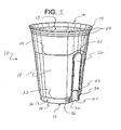
- the container is generally a thermoformed cup 10 including an open top 12 defined by an annular rim 14, a base 16, and a sidewall 18 extending between the top 12 and the base 16.
- the sidewall 18 has at least one recess 20 and an annular shoulder 22 located between the recess 20 and the base 16, and the annular shoulder 22 has at least one arched portion 23.
- the cup 10 also includes at least one annular rib 24 and a lower portion 26 extending between the annular shoulder 22 and the base 16, having at least one beveled portion 27 aligned with the recess 20.
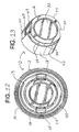
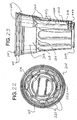
- the top 12 of the cup 10 is a generally circular opening 13 defined by an annular rim 14, as shown in Figures 1 and 4.
- the rim 14 is preferably thicker and rolled toward the outside of the cup 10, which is a common characteristic of thermoformed drinking cups.
- the rolled rim 14 forms a smooth surface for contact with the mouth of a user, as well as providing increased strength and rigidity to the top 12 of the cup 10.
- a rolled rim 14 is preferred, other known rim 14 configurations may be used in accordance with the present invention.
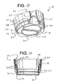
- the base 16 is connected to the lower portion 26 of the sidewall 18, and is generally a circular disk having beveled edges 30 and a circular recess 32 in the center.
- the shape of the base 16 need not be circular, as a multitude of other shapes will function effectively. Additionally, the recess 32 may not be circular, or alternatively, may not be present at all. Notably, the shape of the top 12 need not be the same as the base 16.
- the base 116 is elliptical and the top 112 is circular.
- the base 16 has beveled edges 30 corresponding to the beveled portions 27 of the lower portion 26 of the sidewall 18 (discussed below).
- the beveled edges 30 are concavely curved, as shown in Figures 1 and 8.
- the beveled edges 30 may be straight, as shown in Figures 26 and 27, or may take another shape, but their shape is generally dependent on the shape of the beveled portions 27 of the lower portion 26.
- the recess 32 in the center of the base 16 both improves the rigidity of the base 16 and provides a more stable and balanced surface for resting upon another surface.
- the base 16 is connected to the sidewall 18 around its entire perimeter, forming a base shoulder 34.
- the sidewall 18 connects the top 12 with the base 16, extending between the top 12 and the base 16 and making up the bulk of the container.
- the sidewall 18 is generally cylindrical, as shown in Figures 1-7, and, because the opening 13 is generally larger than the base 16, the sidewall 18 tapers from top 12 to the base 16. In other words, the diameter of the cylinder formed by the sidewall 18 is larger near the top 12 and decreases as the base 16 is approached, creating a frustoconical shape.
- the lower portion 26 of the sidewall 18 preferably has an opposite taper relative to the rest of the sidewall 18.
- the shape of the sidewall 18 is largely dictated by the shapes and sizes of the top 12 and the base 16, and thus, the sidewall 18 may have one of a variety of other shapes.
- the sidewall 18 has several characteristic features, including one or more recesses 20, an annular shoulder 22, a lower portion 26 connecting the annular shoulder 22 to the base 16, and one or more annular ribs 24,28.
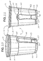
- the sidewall 18 may contain an upper shoulder 46, creating an upper portion 48 extending between the upper shoulder 46 and the container top 12.
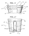
- the upper portion 48 is preferably tapered oppositely to the rest of the sidewall 18, as illustrated in Figure 24.
- the diameter of the upper portion 46 is greater at the upper shoulder 46 than at the top 12 of the cup 10.
- the reverse taper of the upper portion 48 provides a means for stacking a plurality of cups 10, as shown in Figure 24.
- the lower portion 26 need not be reverse-tapered, and can be either completely absent or present only under the arched portions 23.
- the sidewall 18 has two recesses 20.
- These recesses 20 are longitudinal, i.e. having a much larger vertical dimension (perpendicular to the base 16) than a circumferential dimension.
- the recesses 20 are preferably arcuately formed, being circumferentially wider towards the top 12 and bottom and narrower in the middle.
- the preferred recesses 20 are smooth and concave, curving inward toward the center of the cup 10.
- the concavity of the recesses 20 is deeper relative to the rest of the sidewall 18 near the top of the recesses 20, forming a swale 21 in each recess, as illustrated in Figure 7.
- the recesses 20 begin nearer to the top 12 of the cup 10 and preferably terminate at the annular shoulder 22.
- the recesses 20 can take any of a variety of different forms.
- the recesses 20 are preferably longitudinal and arcuately formed, these characteristics are not necessary.
- the degree or smoothness of the concavity of the recesses 20 may vary, and the swales 21 need not be present.
- the recesses 20 may not be concave, being deeply recessed near the edges of the recesses 20 and having a slight convex curvature.
- the surface of the recesses 20 may have ridges or projections (such as a logo) to enhance gripping, rather than being smooth.
- the recesses 20 may be located anywhere on the sidewall 18 and need not terminate at the annular shoulder 22.
- the recesses 20 may exist completely above the annular shoulder 22, or may pass through the annular shoulder 22 and extend to the base 16. Finally, the cup 10 may have any number of recesses 20. In one embodiment discussed below, the cup 10 has as many as twenty or more recesses 20. These recesses 20 serve the dual purpose of providing an ergonomic gripping surface for the user and, as discussed below, significantly increasing the strength and rigidity of the sidewall 18.
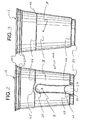
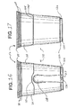
- the annular shoulder 22 exists between the recesses 20 and the base 16, as shown in Figures 2, 5, and 8.
- the annular shoulder 22 is generally circular, except for the arched portions 23 adjacent to the recesses 20.
- the annular shoulder 22 may take another shape, such as an elliptical shape in one embodiment.
- the entire recess 20 is located on the opposite side of the annular shoulder 22 as the base 16, and the recess 20 terminates at the annular shoulder 22.
- the recess 20 exists only on one side of the annular shoulder 22 and the recess 20 ends at the point of contact between the recess 20 and the annular shoulder 22.
- the recesses 20 may pass through the annular shoulder 22, so the shoulder 22 is still considered to exist between the recess 20 and the base 16 as long as a portion of the recess 20 is located on the side of the shoulder 22 opposite the base 16.
- the shoulder 22 includes two arched portions 23 aligned with the two recesses 20.
- the shoulder 22 may contain any number of arched portions 23, and preferably, the shoulder 22 has an arched portion 23 to correspond with every recess 20.
- the arched portions 23 are preferably smoothly curved with a sharp transition 36 between each arched portion 23 and the rest of the annular shoulder 22, as shown in Figures 1, 2, and 8.
- this is not an essential characteristic.
- the arched portions 23 shown in Figures 11 and 13 have a sharp transition 36 and are polygonal in shape, while the arched portions 23 shown in Figures 26 and 27 have a smooth transition 36 and a smoothly curved shape.
- the arched portions 23 may also be square, triangular, or any other shape that accomplishes the functions articulated herein. Further, the arched portions 23 need not be aligned with the recesses, and could be located elsewhere on the annular shoulder 22, for example at a position 90 degrees around the perimeter of the sidewall 18 from the recesses 20. Finally, the annular shoulder 22 is preferably separated completely from the base 16 by the lower portion 26 of the sidewall 18. However, the annular shoulder 22 may be at the bottom of the sidewall 18, directly connecting the sidewall 18 to the base 16, with the lower portion 26 either entirely absent or only intermittently present where the annular shoulder 22 rises to form the arched portions 23, as illustrated in Figure 25. In other words, the annular shoulder 22 may be contiguous, either entirely or in part, with the base shoulder 34 connecting the sidewall 18 to the base 16.
- the sidewall 18 of the cup 10 illustrated in Figures 1-9 has a lower portion 26 separating the annular shoulder 22 from the base 16, the lower portion 26 including two beveled portions 27 aligned with the recesses 20.
- the lower portion 26 is generally annular or cylindrical, and is preferably tapered or flared oppositely to the rest of the sidewall 18, generally to provide a stacking means to a plurality of nested cups 10.
- the diameter of the lower portion 26 near the annular shoulder 22 is slightly smaller than the diameter at the base 16.
- the lower portion 26 illustrated in Figures 5 and 8 is generally circular, but the lower portion 26 may take different shape. In one embodiment, the lower portion 126 is elliptical.
- the lower portion 26 is typically more rigid than the remainder of the sidewall 18 because the annular shoulder 22 and the base shoulder 34 add strength to the lower portion 26. Finally, as described above and shown in Figure 25, the lower portion 26 may be completely absent or only intermittently present beneath the arched portions 23 of the annular shoulder 22, if the annular shoulder 22 is wholly or partially contiguous with the base shoulder 34.
- the lower portion 26 preferably has two beveled portions 27 adjacent to, and aligned with, the arched portions 23 of the annular shoulder 22 and the recesses 20. Any number of beveled portions 27 may be present, or the beveled portions 27 may be entirely absent, but preferably, the lower portion 26 has a beveled portion 27 corresponding to each recess 20.
- the beveled portions 27 extend from the base to the annular shoulder 22, but the beveled portions 27 may alternately only extend a portion of the distance between the base 16 and the annular shoulder 22.
- the beveled portions 27 are concavely curved, as shown in Figures 1 and 8, but this characteristic is not essential.
- the beveled portions 27 may be flat, as shown in Figures 26 and 27, or convexly curved, or could take another form, such as a polygonal shape. Alternately, the base and lower portion could be elliptically shaped to effectively create beveled portions, without any blunt angles. Finally, if the arched portions 23 are not aligned with the recesses 20, the beveled portions 27 may be aligned with either the arched portions 23 or the recesses 20, or aligned with both.
- the cup 10 preferably has a stacking shoulder, generally to provide a stacking means to a plurality of nested cups 10.
- a stacking shoulder can provide a stacking means to a plurality of nested cups 10 in a variety of manners, by providing a point of contact at which a lower cup 10 exerts force to support an upper cup 10 nesting inside the lower cup 10. This is generally accomplished because the rapid change in diameter of the cup created by the stacking shoulder causes a point of contact between the outer surface 42 of the upper cup 10 and the inner surface 40 of the lower cup 10.
- the point of contact can be created, for example, between the stacking shoulder of one cup the top 12, base 16, or stacking shoulder of another cup, providing direct vertical support. Alternately, the point of contact may provide support by frictional force between the sidewalls 18 of two cups 10, rather than direct support.
- the annular shoulder 22 functions as a stacking shoulder. This feature is illustrated, for example, in Figure 23, where a portion of the base 216 sits upon the inner surface 240 of the annular shoulder 222 when one cup 210 is nested upon a second identical cup 210. As shown, the reverse taper of the lower portion 226 aids in providing a more effective stacking means, by allowing the base 216 to be wider in diameter than the annular shoulder 222.
- the cup 10 may have a stacking shoulder located elsewhere, as is known in the art. The stacking shoulder may be located near the top 12 of the cup 10, as illustrated in Figure 24, where the upper shoulder 46 functions as a stacking shoulder.
- cup 10 shown in Figure 24 contains a reverse-tapered upper portion 48, aiding in providing a stacking means, the upper portion 48 need not be reverse-tapered to function effectively.
- Other methods of using a stacking shoulder to provide a stacking means to a plurality of nested cups 10 are known in the art.
- the sidewall 18 has three annular ribs 24,28: two closely spaced ribs 28 near the top 12 and a single central rib 24 approximately at the top of the recess 20.
- the central rib 24 preferably contains two curved portions 25 aligned with the recesses 20. If a different number of recesses 20 are present, the rib 24 preferably contains a curved portion 25 corresponding to each recess 20. Alternately, the curved portions 25 may not be present, especially if the rib 24 is located closer to the top 12 of the cup 10, and does not have to curve around the top of the recess 20. In other embodiments, a greater or fewer number of ribs 24,28 may be present.
- the sidewall 18 has an inner surface 40 and an outer surface 42. Most of the above-mentioned components of the cup 10 are located on the outer surface 42.
- the inner surface 40 includes a raised ledge 44 that is cooperatively dimensioned with the arched portion 23 so that the raised ledge 44 fits within the arched portion 23 of a second identical container when the second container is placed inside the first container.
- the raised ledge 44 is the inverse projection created on the inner surface 40 of the sidewall 18 as the sidewall 18 bends to form the arched portion 23.
- the arched portion 23 and the raised ledge 44 are easily formed with nearly identical dimensions.
- the raised ledge 44 may be a structure separate from the arched portion 23.
- Cooperatively dimensioning the raised ledge 44 and the arched portion 23 is a means of ensuring that two cups 10 nest properly together.
- Such a means of ensuring proper nesting is of key importance in the thermoformed cup industry.
- Standard cylindrical thermoformed cups nest together easily because they are all rotationally symmetrical with each other, i.e. no matter how the cup is rotated about a central longitudinal axis, it will appear identically.
- cups having nonsymmetrical sidewall features, such as vertical ribs, recesses, or embossments will nest together easily, provided that the depth of the nonsymmetrical features is smaller than the width of the air gap that exists between two nested cups.
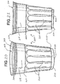
- a third means for ensuring proper nesting is the use of a greater number of recesses 220, consistently spaced on the outer surface 242 of the sidewall 218, projecting deeper into the cup 210 than the recesses 220 of the preferred embodiment, as shown in Figures 20-23.
- the projections of the recesses 220 on the inner surface 240 of the sidewall 218 form ridges 243 that will sit inside the recesses 220 as the cups 210 are stacked together, shown in Figure 23.
- Equidistantly spacing a number of recesses 220 about the circumference of the sidewall 218 creates a number of different positions which effect proper nesting. Consequently, little manipulation may be required for the cup 210 to nest properly.
- the third means Unlike the first two means for ensuring proper nesting, which "urge” the cup into one of a small number of proper nesting positions, the third means "allows” the cup 210 to nest properly by providing a number of different positions in which the cup 210 will nest properly. Still other means of ensuring proper nesting exist.
- the present invention has the additional benefit of limiting movement and wear on the cups 10 during manufacturing. As stated above, movement and rotation of the cups 10 during manufacturing may cause the cups 10 to rub together.
- the means for ensuring proper nesting also limits the rotation of the cups 10 within each other during manufacturing, just as they do when the cups 10 are stacked together in commercial or private use. Once the cups 10 are "locked” into a proper nesting position, they do not rotate within each other or rub together. Thus, the means for ensuring proper nesting provides an additional benefit in the manufacturing of thermoformed cups 10 having longitudinal recesses 20.
- the sidewall 18 increase the strength and rigidity of the sidewall 18, allowing the sidewall 18 to be made thinner, thereby potentially reducing weight and cost.
- Using a thickened, rolled rim 14, annular ribs 24,28, and annular shoulders 22 to increase strength and rigidity is known in the art.
- the present invention achieves greater strength and rigidity through the use of recesses 20 in the sidewall 18, as well as these known means. Longitudinal recesses 20 help to increase rigidity by disrupting the energy transferred to the sidewall 18 by the outside force, in this case, the user's hand.
- the recesses 20 limit the area of the sidewall 18 that "gives" in response to the force, thereby increasing strength and rigidity. It was discovered that longitudinal recesses 20, such as those used in the present invention, provide more strength enhancement if they are concave and arcuately formed. Thus, the longitudinal recesses 20 of the preferred cup 10 are concave and arcuately formed.
- the materials preferred for this standardized procedure include (1) several standard round thermoformed cups, (2) several cups identified herein as the preferred embodiment of the present invention, having longitudinal recesses 20, (3) a Chatillon® DFGS digital force gauge, (4) a Chatillon® TCD-200 tension and compression tester, (5) a container rigidity fixture and (6) Chatillon® AutoTest TM software.
- This standardized procedure involves apparatus set-up and analysis. Specifically, (1) attaching the container rigidity fixture to the compression tester in a level manner, (2) aligning the container mounting fixture to permit test deflection at two-thirds the height of a container, which is the most commonly grasped area during use, (3) zeroing the appropriate gauges, (4) setting the deflection limit at one quarter inch, and (5) setting the travel speeds of the deflection apparatus.
- analyzing sidewall 18 deflection includes (1) placing a first sample into the container mounting fixture, (2) slowly lowering the probe of the force gauge onto the samples, and (3) reading and recording the maximum force value on the gauge as the sidewall 18 of the sample deflects one quarter inch, the limit for deflection. This procedure is duplicated as necessary for analysis and study. It should be noted that the testing illustrated herein was performed on a thermoformed cup having a nominal capacity of 18 oz. While containers of different sizes might test differently, similar results are expected for containers of other common sizes.
- Table I includes the data obtained by testing the deflection at Point A, shown in Figure 3.
- Point A is located on the bare portion of the sidewall 18, at a point two-thirds the height of the cup 10 and intermediate between the two recesses 20.
- the "mean container weight” reflects the average weight of both sets of containers.
- the “mean container force” reflects the average force at which the container sidewall 18 deflected one quarter inch. These two quantities determine the “ratio” which is merely the mean container force divided by the mean container weight.
- the "ratio change” illustrates the improvement in force-to-weight ratio achieved by the present invention.
- Table I Point A on Sidewall Container Type Mean Container Weight Mean Container Force Ratio Ratio Change Standard 0.462 oz. 16.2 oz. 35.1 N/A Embodiments 0.473 oz. 17.4 oz. 36.8 1.7
- Table II includes the data obtained by testing the deflection at Point B, shown in Figure 2.
- Point B is located within one of the longitudinal recesses 20 on the sidewall 18, at a point two-thirds the height of the cup 10 and on the centerline of the recess 20.
- the structural integrity of the sidewall 18 in the recesses 20 is more critical, as the cup 10 is designed so the user's hand exerts pressure on the recesses 20 when gripping the cup 10.
- Table II Point B in Recess Container Type Mean Container Weight Mean Container Force Ratio Ratio Change Standard 0.462 oz. 16.3 oz. 35.3 N/A Embodiments 0.473 oz. 24.0 oz. 50.7 15.4
- the recesses 20 have the further benefit of providing an ergonomic gripping surface for a user to grip the cup 10, an advantage over more rounded designs.
- the contoured surface created by the recesses 20 comfortably accommodates a variety of hand positions.
- the recesses 20 promote gripping by the fingertips, creating a minimal area of contact between the fingertips and the cup 10. This may be beneficial in limiting heat transfer between the cup 10 and the user's hand when an uncomfortably cold beverage is held in the cup 10.
- the recesses 20 are smooth and arcuately formed, creating a comfortable feel when gripped.
- the recesses 20 may also incorporate ridges or other friction-enhancing structures to reduce slippage when the cup 10 is gripped.
- it is beneficial that the recesses 20 provide the most comfortable points for gripping the container, because they are the strongest portions of the sidewall 18, as discussed above.
- the arched portions 23 of the annular shoulder 22 and the beveled portions 27 of the lower portion 26 provide the additional benefit of stabilizing the cup 10 when it is in the hand of the user. Such a means for stabilizing the cup 10 when it is held by a user is desirable to increase the commercial appeal of the cup 10.
- the arched portion 23 can be used to increase stability by the user placing a fingertip underneath the arched portion 23 when holding the cup 10. When the fingertip (preferably the pinky or ring finger) is underneath the arched portion 23, the annular shoulder 22 sits on top of the fingertip, allowing the fingertip to exert both vertical force and rotational leverage on the annular shoulder 22.
- the beveled portion 27 provides a contact surface for the fingertip, further increasing the stability of the cup 10.
- the present invention may be embodied in any one of a vast number of container configurations, limited only by the scope of the Claims.
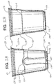
- the container shown in Figures 14-19 is generally a thermoformed drinking cup including an open top 112 defined by a circular, annular rim 114, a base 116, and a sidewall 118 extending between the top 112 and the base 116.
- the sidewall 118 has two longitudinal, arcuately formed recesses 120, an annular shoulder 122 located between the recesses 120 and the base 116, and three annular ribs 124,128.
- This embodiment includes a lower portion 126 extending between the annular shoulder 122 and the base 116 and having two beveled portions 127 aligned with the longitudinal recesses 120, with the recesses 120 terminating at the annular shoulder 122.
- a second key difference is the generally elliptical shape of the base 116, the base recess 132, the lower portion 126, and the annular shoulder 122, as opposed to the circular shape of the preferred embodiment.
- This elliptical shape has two benefits. The first is that it increases strength and rigidity in the recesses 120 by decreasing the radius of curvature near the recesses 120. The second benefit is that, as discussed above, the elliptical shape is another means of ensuring proper nesting.
- the container shown in Figures 20-23 is also generally a thermoformed drinking cup 210 including an open top 212 defined by an annular rim 214, a circular base 216 having a circular base recess 232, and a sidewall 218 extending between the top 212 and the base 216.
- the sidewall 218 of this embodiment includes a lower portion 226 extending between the annular shoulder 222 and the base 216 and three annular ribs 224,228, and the recesses 220 terminate at the annular shoulder 222.
- the sidewall 218 includes a larger number of arcuately formed longitudinal recesses 220.
- the number of longitudinal recesses 220 is generally in the range of from 2 to 12, but is preferably 12, as in Figure 22.
- the cup 10 has as many as twenty recesses 20.
- the potential number of recesses 220 is not limited by the scope of the present invention unless expressly limited, and is only limited by technology and practicality. Most importantly, the optimal number of recesses depends on the size of the container and the width of the recesses.
- the annular shoulder 222 of this embodiment has no arched portions and the lower portion 226 has no beveled portions.
- the large number of longitudinal recesses 220 is beneficial for three reasons.
- the first reason is the great degree of strength and integrity imparted on the sidewall 218 by the presence of the large number of recesses 220.
- the closely spaced recesses 220 disrupt any energy transferred to the sidewall 218 so quickly that the sidewall 218 "gives" very little to pressure at any location.
- the second reason is the ergonomic versatility created by the recesses 220, giving the user a large number of possible positions for holding the cup 210.
- the third reason, as explained above, is that using a large number of recesses 220 in a thin-walled container is an effective means for ensuring proper nesting of the containers upon each other.
- the present invention was developed primarily for use in thermoformed drinking cups. However, the principles of the present invention are beneficial when applied to a multitude of other types of containers. Drinking cups made of any type of polymer, such as clear, opaque, or colored plastics or foam materials may be used in accordance with the present invention, as may cups made of non-polymeric materials. Many types of containers other than cups may also benefit from use of the disclosed features.
Claims (19)
- Behälter (10), der ein durch einen ringförmigen Rand (14) definiertes offenes oberes Ende (12), einen Boden (16) und eine Seitenwand (18), die sich zwischen dem oberen Ende (12) und dem Boden (16) erstreckt, aufweist, wobei die Seitenwand (18) eine innere Oberfläche (40) und eine äußere Oberfläche (42) hat;
dadurch gekennzeichnet, dass die Seitenwand (18) eine Aussparung (20) und einen zwischen der Aussparung (20) und dem Boden (16) angeordneten ringförmigen Absatz (22) umfasst, wobei der ringförmige Absatz (22) einen bogenförmigen Abschnitt (23) umfasst und eine innere Stapeloberfläche auf der inneren Oberfläche (40) der Seitenwand (18) bildet, und der bogenförmige Abschnitt (23) einen erhöhten Vorsprung (44) auf der inneren Stapeloberfläche bildet, und wobei, wenn ein zweiter identischer Behälter (10) in den Behälter (10) gesteckt wird, der Boden (16) des zweiten identischen Behälters (10) auf der inneren Stapeloberfläche ruht und der erhöhte Vorsprung (44) innerhalb des bogenförmigen Abschnitts (23) des zweiten identischen Behälters (10) sitzt. - Behälter (10) nach Anspruch 1, bei dem der ringförmige Absatz (22) weiter ein Mittel zur Stabilisierung des Behälters (10), wenn der Behälter (10) von einem Benutzer gehalten wird, umfasst.
- Behälter (10) nach Anspruch 1, bei dem die Aussparung (20) an dem ringförmigen Absatz (22) aufhört.
- Behälter (10) nach Anspruch 1, bei dem die Seitenwand (18) weiter eine ringförmige Rippe (24) umfasst.
- Behälter (10) nach Anspruch 1, bei dem die Seitenwand (18) weiter mehrere ringförmige Rippen (24) umfasst, von denen zumindest eine einen gekrümmten Abschnitt (25) umfasst, der nach der Aussparung (20) ausgerichtet ist.
- Behälter (10) nach Anspruch 1, bei dem die Aussparung (20) längslaufend und bogenförmig ausgebildet ist.
- Behälter (10) nach Anspruch 1, der weiter ein messbar verbessertes Festigkeits-Gewichts-Verhältnis gegenüber einer im Wesentlichen ähnlichen Seitenwand (18), die keine Aussparungen (20) aufweist, umfasst.
- Behälter (10) nach Anspruch 1, der weiter ein verbessertes Festigkeits-Gewichts-Verhältnis von mindestens 3% gegenüber einer im Wesentlichen ähnlichen Seitenwand (18), die keine Aussparungen (20) aufweist, umfasst.
- Behälter (10) nach Anspruch 1, der weiter ein verbessertes Festigkeits-Gewichts-Verhältnis von mindestens 20% gegenüber einer im Wesentlichen ähnlichen Seitenwand (18), die keine Aussparungen (20) aufweist, umfasst.
- Behälter (10) nach Anspruch 1, der weiter ein verbessertes Festigkeits-Gewichts-Verhältnis von mindestens 40% gegenüber einer im Wesentlichen ähnlichen Seitenwand (18), die keine Aussparungen (20) aufweist, umfasst.
- Behälter (10) nach Anspruch 1, bei dem die Seitenwand (18) weiter einen unteren Abschnitt (26) umfasst, der sich zwischen dem ringförmigen Absatz (22) und dem Boden (16) erstreckt, wobei der untere Abschnitt (26) einen abgeschrägten Abschnitt (27) umfasst, der nach der Aussparung (20) ausgerichtet ist.
- Behälter (10) nach Anspruch 1, bei dem die Seitenwand (18) weiter einen unteren Abschnitt (26) umfasst, der sich zwischen dem ringförmigen Absatz (22) und dem Boden (16) erstreckt, wobei der untere Abschnitt (26) einen abgeschrägten Abschnitt (27) umfasst, der nach dem bogenförmigen Abschnitt (23) ausgerichtet ist.
- Behälter (10) nach Anspruch 1, bei dem der Boden im Wesentlichen kreisförmig ist und durch einen äußersten Rand (34) der untersten Oberfläche des Behälters (10) definiert wird, und die Seitenwand (18) weiter einen unteren Abschnitt (26) umfasst, der sich zwischen dem ringförmigen Absatz (22) und dem Boden (16) erstreckt, wobei zumindest ein Teil des unteren Abschnitts (26) von dem ringförmigen Absatz (22) zu dem Boden (16) äußerlich konisch zulaufend ist, und der untere Abschnitt (26) weiter einen abgeschrägten Abschnitt (27) umfasst, der sich von dem bogenförmigen Abschnitt (23) des ringförmigen Absatzes (22) zu dem Boden (16) erstreckt, wobei der abgeschrägte Abschnitt (27) einen abgeschrägten Randabschnitt (30) auf dem äußersten Rand, der den Boden (16) definiert, bildet.
- Behälter (10) nach Anspruch 13, bei dem die Aussparung (20) längslaufend und nicht nach dem bogenförmigen Abschnitt (23) ausgerichtet ist.
- Behälter (10) nach Anspruch 13, bei dem der abgeschrägte Randabschnitt (30) radial einwärts eines äußersten Umfangs des im Wesentlichen kreisförmigen Bodens (16) angeordnet ist.
- Behälter (10) nach Anspruch 1, bei dem die Aussparung (20) ein Mittel zur Verbesserung des Greifens des Behälters (10) durch einen Benutzer umfasst.
- Behälter (10) nach Anspruch 1, bei dem die Aussparung (20) an dem ringförmigen Absatz (22) aufhört.
- Behälter (10) nach Anspruch 1, bei dem sich der ringförmige Absatz (22) nahe bei dem Boden (16) befindet.
- Behälter (10) nach Anspruch 1, bei dem die Seitenwand (18) weiter einen unteren Abschnitt (26) umfasst, der sich zwischen dem ringförmigen Absatz (22) und dem Boden (16) erstreckt, wobei zumindest ein Teil des unteren Abschnitts (26) von dem ringförmigen Absatz (22) zu dem Boden (16) äußerlich konisch zulaufend ist.
Applications Claiming Priority (2)
| Application Number | Priority Date | Filing Date | Title |
|---|---|---|---|
| US10/676,807 US7546932B2 (en) | 2003-10-01 | 2003-10-01 | Ergonomic disposable cup having improved structural integrity |
| PCT/US2004/009357 WO2005042356A1 (en) | 2003-10-01 | 2004-03-26 | Ergonomic disposable cup having improved structural integrity |
Publications (2)
| Publication Number | Publication Date |
|---|---|
| EP1670688A1 EP1670688A1 (de) | 2006-06-21 |
| EP1670688B1 true EP1670688B1 (de) | 2008-01-02 |
Family
ID=34314040
Family Applications (1)
| Application Number | Title | Priority Date | Filing Date |
|---|---|---|---|
| EP04749453A Expired - Lifetime EP1670688B1 (de) | 2003-10-01 | 2004-03-26 | Ergonomischer wegwerf-becher mit verbesserter formfestigkeit |
Country Status (15)
| Country | Link |
|---|---|
| US (2) | US7546932B2 (de) |
| EP (1) | EP1670688B1 (de) |
| JP (1) | JP2007507400A (de) |
| CN (1) | CN1898133A (de) |
| AR (1) | AR043955A1 (de) |
| AT (1) | ATE382549T1 (de) |
| AU (1) | AU2004285842A1 (de) |
| CA (1) | CA2540919A1 (de) |
| CL (1) | CL2004000608A1 (de) |
| DE (1) | DE602004011088T2 (de) |
| HK (1) | HK1093050A1 (de) |
| MX (1) | MXPA06003637A (de) |
| PA (1) | PA8605601A1 (de) |
| TW (1) | TWI288619B (de) |
| WO (1) | WO2005042356A1 (de) |
Cited By (5)
| Publication number | Priority date | Publication date | Assignee | Title |
|---|---|---|---|---|
| US8146796B2 (en) | 2001-01-30 | 2012-04-03 | Seda S.P.A. | Cardboard container for drinks and process therefor |
| US8146797B2 (en) | 2005-11-11 | 2012-04-03 | Seda S.P.A. | Insulated cup |
| US8360263B2 (en) | 2005-04-15 | 2013-01-29 | Seda S.P.A. | Insulated container, method of fabricating same and apparatus for fabricating |
| US8393886B2 (en) | 2005-11-14 | 2013-03-12 | Seda S.P.A. | Device for producing a stacking projection and container with same |
| US8490792B2 (en) | 2006-12-05 | 2013-07-23 | Seda S.P.A. | Package |
Families Citing this family (92)
| Publication number | Priority date | Publication date | Assignee | Title |
|---|---|---|---|---|
| US9089233B2 (en) | 2003-11-05 | 2015-07-28 | Govino, Llc | Wine glass |
| US20070119726A1 (en) * | 2004-11-01 | 2007-05-31 | Willat | Wine glass |
| US7886924B2 (en) * | 2003-11-05 | 2011-02-15 | By The Glass, Llc | Wine glass |
| US20050189361A1 (en) * | 2004-02-17 | 2005-09-01 | Wincup Holdings, Inc. | Beverage cup for placement in holder |
| CN101327648B (zh) * | 2004-04-08 | 2011-05-11 | 达特食品容器公司 | 形成包装泡沫杯的设备 |
| US20060076395A1 (en) * | 2004-10-12 | 2006-04-13 | Hayes Thomas J | Container having textured grip and enhanced wall integrity |
| WO2006093952A1 (en) * | 2005-03-01 | 2006-09-08 | Pactiv Corporation | Container having textured grip and enhanced wall integrity |
| US20060249518A1 (en) * | 2005-05-09 | 2006-11-09 | Alfred Festa | Drinking glass for containing wine and for optimizing air mixed into the wine during swirling to enhance bouquet |
| DE202005014177U1 (de) | 2005-09-08 | 2005-11-17 | Seda S.P.A., Arzano | Doppelwandiger Becher |
| FR2892094B1 (fr) * | 2005-10-18 | 2008-01-25 | Sparflex Sa | Coiffe de surbouchage a dispositif anti-tassement d'emboitage, procede et manchon pour fabrication |
| DE202007002213U1 (de) * | 2007-02-12 | 2007-04-12 | Jokey Plastik Wipperfuerth | Behälter |
| DE102007007171A1 (de) * | 2007-02-09 | 2008-08-28 | Jokey-Plastik Wipperfürth Gmbh | Behälter mit Deckel und Verfahren zu seiner Herstellung |
| CA2688149A1 (en) * | 2007-05-25 | 2008-12-04 | Duane Ebesu | Balanced individual dining plate |
| GB2449721A (en) * | 2007-09-24 | 2008-12-03 | Vernacare Ltd | Receptacles, particularly of moulded paper pulp |
| USD613554S1 (en) * | 2008-03-14 | 2010-04-13 | Solo Cup Operating Corporation | Cup |
| USD608591S1 (en) * | 2008-06-18 | 2010-01-26 | Solo Cup Operating Corporation | Cup |
| US20110204069A1 (en) * | 2008-07-30 | 2011-08-25 | Jonathan Moon | Thermally insulated optical effect container and method of forming same |
| USD612202S1 (en) | 2009-05-27 | 2010-03-23 | Solo Cup Operating Corporation | Cup |
| US20110095038A1 (en) * | 2009-10-23 | 2011-04-28 | Williams Jr Donald E | Apparatus for consuming liquids |
| US20110220665A1 (en) * | 2010-03-12 | 2011-09-15 | Sean McDonnell | Drinking Game Cup or Attachment |
| DE102010015415B4 (de) * | 2010-04-19 | 2021-08-19 | Optipack Gmbh | Behälter |
| USD649397S1 (en) | 2010-04-30 | 2011-11-29 | Pactiv Corporation | Sidewall for a cup |
| USD649396S1 (en) | 2010-04-30 | 2011-11-29 | Pactiv Corporation | Sidewall for a cup |
| US8523006B2 (en) * | 2010-12-29 | 2013-09-03 | Easypak Llc | Container with integrated structural reinforcement |
| USD852583S1 (en) | 2011-06-16 | 2019-07-02 | Huhtamaki, Inc. | Disposable cup |
| US9314089B2 (en) | 2011-06-16 | 2016-04-19 | Huhtamaki, Inc. | Container having enhanced wall integrity and alignment element |
| WO2013101301A2 (en) * | 2011-06-17 | 2013-07-04 | Berry Plastics Corporation | Insulated sleeve for a cup |
| US8794440B2 (en) * | 2011-07-11 | 2014-08-05 | Kraft Foods Group Brands Llc | Tray with ribs configured for redirecting compressive loads |
| US9010759B2 (en) * | 2011-11-28 | 2015-04-21 | Sean Michael McDonnell | Drinking game cup or attachment with magnetic alignment pad |
| USD687297S1 (en) | 2012-10-26 | 2013-08-06 | Printpack Illinois, Inc. | Container with castle-shaped base |
| USD686916S1 (en) | 2012-10-26 | 2013-07-30 | Printpack Illinois, Inc. | Container with castle-shaped base |
| WO2014071002A1 (en) * | 2012-11-01 | 2014-05-08 | Mark Innovations LLC | Sanitary toilet plunger containment system |
| EP4316324A3 (de) | 2013-03-15 | 2024-03-13 | Vita-Mix Management Corporation | Elektrisch betriebener mischbehälter |
| US9657155B2 (en) | 2013-04-12 | 2017-05-23 | Printpack Illinois, Inc. | Containers and materials with improved punctureability |
| US20140312067A1 (en) * | 2013-04-22 | 2014-10-23 | C. Gary Loomis | Stackable Liquid Pitcher |
| TWD164700S (zh) * | 2013-07-01 | 2014-12-11 | 三得利食品飲料股份有限公 | 包裝用容器 |
| USD745825S1 (en) * | 2013-07-01 | 2015-12-22 | Suntory Beverage & Food Limited | Packaging container |
| USD715649S1 (en) | 2013-07-09 | 2014-10-21 | Printpack Illinois, Inc. | Container |
| USD720613S1 (en) | 2013-09-09 | 2015-01-06 | Kraft Foods Group Brands Llc | Container |
| CA3135204C (en) | 2013-09-09 | 2023-09-19 | Kraft Foods Group Brands Llc | Container and lid |
| USD753482S1 (en) * | 2013-09-13 | 2016-04-12 | Tricorbraun Inc. | Tub |
| USD734988S1 (en) | 2014-03-06 | 2015-07-28 | Euro-Pro Operating Llc | Blender container |
| USD798718S1 (en) | 2014-06-10 | 2017-10-03 | Printpack Illinois, Inc. | Container with cone-shaped base |
| JP2017522918A (ja) | 2014-06-10 | 2017-08-17 | プリントパック イリノイ インコーポレイテッド | 改善された穴開け容易性(punctureability)を有する容器 |
| USD745386S1 (en) * | 2014-12-23 | 2015-12-15 | Food & Beverage Innovations, Llc | Pod |
| US9675212B2 (en) | 2015-02-03 | 2017-06-13 | Sharkninja Operating Llc | Container for food processing system |
| JP6506607B2 (ja) * | 2015-04-27 | 2019-04-24 | 中央化学株式会社 | 包装用容器 |
| USD764231S1 (en) * | 2015-05-18 | 2016-08-23 | Ideavillage Products Corp. | Container with insert and lid |
| USD783355S1 (en) * | 2015-07-17 | 2017-04-11 | Sharkninja Operating Llc | Blender attachment |
| USD769070S1 (en) | 2015-11-20 | 2016-10-18 | Hexcup, LLC | Hexagonal cup |
| US10477998B2 (en) * | 2016-03-01 | 2019-11-19 | Berry Plastics Corporation | Drink cup |
| USD830124S1 (en) * | 2016-03-04 | 2018-10-09 | Vita-Mix Management Corporation | Container |
| USD815912S1 (en) | 2016-08-04 | 2018-04-24 | Govino, Llc | Stackable glass |
| US10889411B2 (en) * | 2017-02-03 | 2021-01-12 | Berry Plastics Corporation | Container with lid and detachable lid collar |
| US11370579B2 (en) | 2017-02-07 | 2022-06-28 | Ball Corporation | Tapered metal cup and method of forming the same |
| US10875076B2 (en) | 2017-02-07 | 2020-12-29 | Ball Corporation | Tapered metal cup and method of forming the same |
| US10716427B2 (en) | 2017-02-14 | 2020-07-21 | Portage Plastics Corporation | Single-serving beverage cartridge container |
| USD839670S1 (en) | 2017-02-16 | 2019-02-05 | Vita-Mix Management Corporation | Blending container |
| USD851998S1 (en) | 2017-02-28 | 2019-06-25 | Berry Plastics Corporation | Portion of a drink cup |
| US10577159B2 (en) | 2017-04-07 | 2020-03-03 | Berry Plastics Corporation | Drink cup lid |
| USD842566S1 (en) | 2017-06-15 | 2019-03-05 | Vita-Mix Management Corporation | Container scraper |
| CN107386014B (zh) * | 2017-07-06 | 2023-06-20 | 江苏绿森包装有限公司 | 纸浆模塑负角度容器及其加工工艺 |
| US11040499B2 (en) | 2017-08-07 | 2021-06-22 | Berry Global, Inc. | Method and apparatus for thermoforming an article |
| US10172497B1 (en) * | 2017-11-09 | 2019-01-08 | John J. Romano | Bread storage dispenser device |
| USD937631S1 (en) * | 2017-11-20 | 2021-12-07 | Reynolds Consumer Products LLC | Sidewall for a cup |
| USD856807S1 (en) * | 2017-11-29 | 2019-08-20 | Manavlar Gida Sanayi Ve Ticaret Limited Sirketi | Glass jar |
| US11089906B2 (en) | 2018-04-05 | 2021-08-17 | Vinglacé, LLC | Insulated food and beverage container |
| US11786061B2 (en) | 2018-04-05 | 2023-10-17 | Vinglace Llc | Insulated food and beverage container |
| USD950318S1 (en) | 2018-05-24 | 2022-05-03 | Ball Corporation | Tapered cup |
| USD867127S1 (en) * | 2018-05-31 | 2019-11-19 | Ipl Inc. | Ice cream container |
| USD948331S1 (en) | 2018-07-31 | 2022-04-12 | Kraft Foods Group Brands Llc | Container |
| USD871852S1 (en) | 2018-08-09 | 2020-01-07 | Vinglacé, LLC | Beverage tumbler |
| USD907997S1 (en) | 2018-08-10 | 2021-01-19 | Berry Global, Inc. | Drink cup lid |
| USD918033S1 (en) | 2018-10-02 | 2021-05-04 | Kraft Foods Group Brands Llc | Container |
| USD967702S1 (en) | 2018-10-02 | 2022-10-25 | Kraft Foods Group Brands Llc | Container |
| USD885842S1 (en) | 2018-10-25 | 2020-06-02 | Huhtamaki, Inc. | Disposable cup |
| USD906056S1 (en) | 2018-12-05 | 2020-12-29 | Ball Corporation | Tapered cup |
| PE20211718A1 (es) * | 2018-12-10 | 2021-09-03 | Ball Corp | Vaso de metal conico y metodo de conformacion del mismo |
| US11891488B2 (en) | 2019-02-06 | 2024-02-06 | Berry Global, Inc. | Polypropylene sheets and articles |
| WO2020163472A1 (en) | 2019-02-06 | 2020-08-13 | Berry Global, Inc. | Process of forming polymeric material |
| USD911168S1 (en) | 2019-03-05 | 2021-02-23 | Berry Global, Inc. | Drink cup lid |
| USD910435S1 (en) | 2019-03-13 | 2021-02-16 | Kraft Foods Group Brands Llc | Container |
| USD968893S1 (en) | 2019-06-24 | 2022-11-08 | Ball Corporation | Tapered cup |
| USD885137S1 (en) | 2020-01-10 | 2020-05-26 | Vinglacé, LLC | Beverage tumbler |
| USD885136S1 (en) | 2020-01-10 | 2020-05-26 | Vinglacé, LLC | Beverage Container |
| USD953811S1 (en) | 2020-02-14 | 2022-06-07 | Ball Corporation | Tapered cup |
| USD898522S1 (en) | 2020-03-04 | 2020-10-13 | Vinglacé, LLC | Beverage flute |
| USD974845S1 (en) | 2020-07-15 | 2023-01-10 | Ball Corporation | Tapered cup |
| GB202011070D0 (en) * | 2020-07-17 | 2020-09-02 | Innavisions Ltd | Improvements in or relating to moulded containers |
| USD1012617S1 (en) | 2021-02-22 | 2024-01-30 | Ball Corporation | Tapered cup |
| USD987379S1 (en) | 2021-06-10 | 2023-05-30 | Vinglace Llc | Drinkware |
| WO2023018702A1 (en) * | 2021-08-10 | 2023-02-16 | Silgan Containers Llc | Thin-walled metal cup |
Family Cites Families (90)
| Publication number | Priority date | Publication date | Assignee | Title |
|---|---|---|---|---|
| DE285032C (de) * | ||||
| DE328014C (de) * | 1920-10-20 | Friedrich Stendebach | Einrichtung an Handfeuerwaffen zur Verhuetung des Eindringens von Gasen in das Schloss | |
| DE223999C (de) * | ||||
| DE272794C (de) * | ||||
| DE346308C (de) * | ||||
| DE198139C (de) * | ||||
| DE187079C (de) * | ||||
| DE228125C (de) * | ||||
| US3126139A (en) | 1964-03-24 | Partially insulated plastic container | ||
| US703125A (en) | 1901-09-28 | 1902-06-24 | Henry C Emrich | Milk jar or bottle. |
| DE387619C (de) * | 1921-09-17 | 1924-01-02 | Jens Lillesoee | Vorrichtung zum Anbringen des Wagenkastens an sowohl vorn als hinten gefederten Motorradseitenwagen |
| DE368234C (de) * | 1922-02-28 | 1923-01-29 | Paul Mecke Dr | Verfahren zur Herstellung haltbarer OElemulsionen fuer Anstriche und zur Bereitung von OElfarben |
| DE410174C (de) * | 1922-03-18 | 1925-02-21 | Atlantic Akt Ges Fuer Automobi | Rahmen fuer Einspurkraftfahrzeuge |
| DE413067C (de) * | 1923-05-01 | 1925-05-06 | August Robert Mueller | Verfahren zur Befestigung eines Kontaktstueckes in Isolierkoerpern |
| DE399099C (de) * | 1923-07-29 | 1924-07-29 | Georg S Ullrich | Mahlvorrichtung mit Anwendung des Magnetismus als Druckkraft |
| DE416757C (de) * | 1924-04-08 | 1925-07-28 | Hermann Kolodzinski | Kontaktvorrichtung fuer auf Fahrzeugen anzubringende elektrische Kilometerzaehler mit Kontaktscheiben |
| US1636174A (en) | 1924-07-31 | 1927-07-19 | United Ammonia Company Inc | Bottle |
| GB395996A (en) | 1932-08-22 | 1933-07-27 | Charles Berneaud | An improved jar adapted for the packing of salted herrings |
| US2013243A (en) | 1933-06-02 | 1935-09-03 | Frank H Landon | Container |
| US2629534A (en) | 1947-10-08 | 1953-02-24 | Julian L Reynolds | Container |
| US2745586A (en) | 1953-07-06 | 1956-05-15 | Edwin L Thoma | Paper cup with a stirring spoon made unitary therewith |
| NL233410A (de) | 1957-11-29 | |||
| DE1175564B (de) | 1957-11-29 | 1964-08-06 | Illinois Tool Works | Becher |
| US2905350A (en) | 1957-11-29 | 1959-09-22 | Illinois Tool Works | Cup for hot beverages |
| US3009603A (en) | 1958-06-16 | 1961-11-21 | Illinois Tool Works | Plastic flower pot |
| US3085730A (en) | 1961-05-01 | 1963-04-16 | Illinois Tool Works | Plastic containers |
| GB1032041A (en) | 1961-06-16 | 1966-06-08 | Mono Containers Ltd | Improvements in or relating to containers |
| US3094240A (en) * | 1962-03-22 | 1963-06-18 | Illinois Tool Works | Molded nestable container having indicia protection means |
| BE636476A (de) * | 1962-12-14 | |||
| DE1216139B (de) | 1963-11-11 | 1966-05-05 | Somerville Ind Ltd | Im Spritzgussverfahren aus Kunststoff hergestellter duennwandiger Becher |
| GB1096451A (en) | 1964-03-26 | 1967-12-29 | Mono Containers Ltd | Drinking vessels and like containers |
| US3288340A (en) | 1964-05-25 | 1966-11-29 | Sweetheart Plastics | Nestable container |
| NL146761B (nl) | 1965-12-24 | 1975-08-15 | Impromex A G | Beker, in het bijzonder van kunststof. |
| US3342370A (en) | 1966-04-08 | 1967-09-19 | Borden Chemical Company | Nestable cup construction |
| US3375954A (en) | 1966-10-19 | 1968-04-02 | American Can Co | Nestable container |
| US3437253A (en) | 1968-01-12 | 1969-04-08 | Sweetheart Plastics | Disposable plastic cup with stiff gripping section |
| US3443715A (en) | 1968-01-18 | 1969-05-13 | Illinois Tool Works | Double wall container |
| US3519165A (en) * | 1969-03-17 | 1970-07-07 | American Can Co | Cup stacking means |
| US3934725A (en) * | 1972-03-13 | 1976-01-27 | Illinois Tool Works Inc. | Nestable article |
| NL176520C (nl) | 1972-05-26 | Mars Ltd | Drinkbeker. | |
| CH559137A5 (de) | 1972-11-25 | 1975-02-28 | Fernholz Fa | |
| GB1461394A (en) | 1973-03-12 | 1977-01-13 | Illinois Tool Works | Nestable articles |
| US3951266A (en) | 1974-06-21 | 1976-04-20 | Solo Cup Company | Thin walled cup |
| US4049187A (en) | 1974-10-02 | 1977-09-20 | Mobil Oil Corporation | Thermoformed hot drink cup |
| US4061782A (en) | 1975-05-27 | 1977-12-06 | Redimix Beverages Limited | Beverage package cup |
| JPS5748463Y2 (de) * | 1975-06-21 | 1982-10-23 | ||
| US4134492A (en) | 1976-10-22 | 1979-01-16 | Lucas Paul A | Coffee cup and container |
| US4102454A (en) | 1977-04-27 | 1978-07-25 | Huhtamaki Oy | Conical disposable mug |
| US4245685A (en) | 1978-08-15 | 1981-01-20 | Mallinckrodt, Inc. | Protective carrier |
| US4420081A (en) | 1981-06-22 | 1983-12-13 | Dart Container Corporation | Step-wall nestable cup |
| USD272794S (en) | 1981-06-22 | 1984-02-28 | Dart Container Corporation | Beverage cup |
| US4578296A (en) | 1983-06-28 | 1986-03-25 | Idemitsu Petrochemical Co., Ltd. | Thermoformed polyolefin cup |
| USD285032S (en) | 1983-10-31 | 1986-08-12 | Alonzo Patrick R | Beverage tumbler or the like |
| US4548348A (en) | 1984-02-27 | 1985-10-22 | Solo Cup Company | Disposable cup assembly |
| CH676352A5 (de) | 1988-11-29 | 1991-01-15 | Sandherr Packungen Ag | |
| USD328014S (en) | 1990-05-08 | 1992-07-21 | Dart Industries, Inc. | Covered container or the like |
| US5082135A (en) | 1990-05-08 | 1992-01-21 | Dart Industries Inc. | Container for storing and dispensing goods |
| USD346308S (en) | 1992-08-20 | 1994-04-26 | Dart Industries Inc. | Drinking tumbler |
| SE508747C2 (sv) | 1992-10-07 | 1998-11-02 | Tetra Laval Holdings & Finance | Sätt att framställa invändigt sterila, skål- eller bägarformiga behållare |
| US5415339A (en) | 1993-04-21 | 1995-05-16 | Howard; Jeremy C. | Drinking cup with open ribbed sidewall |
| DE4419161C2 (de) | 1994-06-01 | 1996-11-07 | Polarcup Gmbh | Dünnwandiger Behälter aus Kunststoff |
| USD368234S (en) | 1994-12-05 | 1996-03-26 | Contico International, Inc. | Flower pot |
| US5678726A (en) | 1995-07-03 | 1997-10-21 | Porteous; Don D. | Aliquot portion measuring vial with overfill control |
| US5634569A (en) | 1996-01-18 | 1997-06-03 | Dart Industries Inc. | Food container with dispensing means |
| USD387619S (en) | 1996-08-21 | 1997-12-16 | Brown Wood Products Co. | Wooden coffee tumbler |
| USD413067S (en) | 1997-03-31 | 1999-08-24 | Rubbermaid Incorporated | Bottle |
| USD399099S (en) | 1997-07-03 | 1998-10-06 | Dart Industries Inc. | Window canister |
| US6062409A (en) * | 1997-12-05 | 2000-05-16 | Crown Cork & Seal Technologies Corporation | Hot fill plastic container having spaced apart arched ribs |
| US6264068B1 (en) | 1998-01-06 | 2001-07-24 | Kellogg Company | One-handed container for dispensing a solid and a liquid |
| DE29802377U1 (de) | 1998-02-12 | 1998-05-14 | Sibec Sachsen Bvh Export Impor | Stapelfähiger Trinkbecher aus Kunststoff |
| DE19840841B4 (de) | 1998-09-07 | 2007-02-08 | Michael Hörauf Maschinenfabrik GmbH & Co. KG | Wärmeisolierender Becher |
| USD410174S (en) | 1998-09-15 | 1999-05-25 | James Sheu | Thermal cup |
| USD446687S1 (en) | 1998-10-13 | 2001-08-21 | Wincup Holdings, Inc. | Cup |
| USD436295S1 (en) | 1998-10-13 | 2001-01-16 | Wincup Holdings, Inc. | Cup |
| USD416757S (en) | 1998-11-10 | 1999-11-23 | Pacific Market, Inc. | Banded tumbler |
| GB2352612A (en) | 1999-07-28 | 2001-02-07 | Autobar Ind Ltd | Nestable drinking cups with swirl means |
| USD441252S1 (en) | 1999-09-14 | 2001-05-01 | Solo Cup Company | Sidewall for a cup |
| USD443475S1 (en) | 1999-10-07 | 2001-06-12 | San-Ai Corporation | Cup for beverages or food |
| USD444672S1 (en) | 1999-10-29 | 2001-07-10 | San-Ai Corporation | Cup for beverages or foods |
| USD448976S1 (en) | 1999-12-30 | 2001-10-09 | Johnson & Johnson Consumer Companies, Inc. | Pinched trainer cup |
| USD446684S1 (en) | 2000-01-31 | 2001-08-21 | Punch Products Usa, Inc. | Mug |
| US6554154B1 (en) | 2000-02-11 | 2003-04-29 | Solo Cup Company | Thermoformed container having improved strength to weight ratio in sidewall |
| JP3875457B2 (ja) * | 2000-06-30 | 2007-01-31 | 株式会社吉野工業所 | 減圧吸収壁を備えるボトル型容器 |
| US6528105B1 (en) | 2000-07-14 | 2003-03-04 | Kellogg Company | Single handed container for mixing foods |
| USD461369S1 (en) * | 2001-04-03 | 2002-08-13 | Berry Plastics Corporation | Cup |
| US7017773B2 (en) | 2002-09-09 | 2006-03-28 | Rehrig Pacific Company | Waste container |
| USD514380S1 (en) * | 2003-10-01 | 2006-02-07 | Solo Cup Company | Ergonomic disposable cup |
| USD514385S1 (en) * | 2003-10-01 | 2006-02-07 | Solo Cup Company | Ergonomic disposable cup |
| USD499935S1 (en) * | 2003-10-01 | 2004-12-21 | Solo Cup Company | Ergonomic disposable cup |
| USD511647S1 (en) * | 2003-10-01 | 2005-11-22 | Solo Cup Company | Shoulder of a disposable cup |
-
2003
- 2003-10-01 US US10/676,807 patent/US7546932B2/en active Active
-
2004
- 2004-03-23 CL CL200400608A patent/CL2004000608A1/es unknown
- 2004-03-26 WO PCT/US2004/009357 patent/WO2005042356A1/en active IP Right Grant
- 2004-03-26 AU AU2004285842A patent/AU2004285842A1/en not_active Abandoned
- 2004-03-26 AT AT04749453T patent/ATE382549T1/de not_active IP Right Cessation
- 2004-03-26 JP JP2006532347A patent/JP2007507400A/ja active Pending
- 2004-03-26 EP EP04749453A patent/EP1670688B1/de not_active Expired - Lifetime
- 2004-03-26 CN CNA2004800354227A patent/CN1898133A/zh active Pending
- 2004-03-26 CA CA002540919A patent/CA2540919A1/en not_active Abandoned
- 2004-03-26 DE DE602004011088T patent/DE602004011088T2/de not_active Expired - Lifetime
- 2004-03-26 MX MXPA06003637A patent/MXPA06003637A/es active IP Right Grant
- 2004-03-29 AR ARP040101043A patent/AR043955A1/es unknown
- 2004-04-02 TW TW093109263A patent/TWI288619B/zh not_active IP Right Cessation
- 2004-06-30 PA PA20048605601A patent/PA8605601A1/es unknown
-
2005
- 2005-04-08 US US11/101,932 patent/US8152018B2/en active Active
-
2006
- 2006-12-18 HK HK06113900A patent/HK1093050A1/xx not_active IP Right Cessation
Cited By (7)
| Publication number | Priority date | Publication date | Assignee | Title |
|---|---|---|---|---|
| US8146796B2 (en) | 2001-01-30 | 2012-04-03 | Seda S.P.A. | Cardboard container for drinks and process therefor |
| US8360263B2 (en) | 2005-04-15 | 2013-01-29 | Seda S.P.A. | Insulated container, method of fabricating same and apparatus for fabricating |
| US8794294B2 (en) | 2005-04-15 | 2014-08-05 | Seda S.P.A. | Insulated container, method of fabricating same and apparatus for fabricating |
| US8932428B2 (en) | 2005-04-15 | 2015-01-13 | Seda S.P.A. | Insulated container, method of fabricating same and apparatus for fabricating |
| US8146797B2 (en) | 2005-11-11 | 2012-04-03 | Seda S.P.A. | Insulated cup |
| US8393886B2 (en) | 2005-11-14 | 2013-03-12 | Seda S.P.A. | Device for producing a stacking projection and container with same |
| US8490792B2 (en) | 2006-12-05 | 2013-07-23 | Seda S.P.A. | Package |
Also Published As
| Publication number | Publication date |
|---|---|
| US8152018B2 (en) | 2012-04-10 |
| US7546932B2 (en) | 2009-06-16 |
| CL2004000608A1 (es) | 2005-03-18 |
| CN1898133A (zh) | 2007-01-17 |
| US20050173287A1 (en) | 2005-08-11 |
| AU2004285842A1 (en) | 2005-05-12 |
| EP1670688A1 (de) | 2006-06-21 |
| CA2540919A1 (en) | 2005-05-12 |
| JP2007507400A (ja) | 2007-03-29 |
| DE602004011088T2 (de) | 2009-01-02 |
| ATE382549T1 (de) | 2008-01-15 |
| DE602004011088D1 (de) | 2008-02-14 |
| AR043955A1 (es) | 2005-08-17 |
| MXPA06003637A (es) | 2006-06-20 |
| HK1093050A1 (en) | 2007-02-23 |
| US20050061821A1 (en) | 2005-03-24 |
| PA8605601A1 (es) | 2005-05-24 |
| TW200513215A (en) | 2005-04-16 |
| WO2005042356A1 (en) | 2005-05-12 |
| TWI288619B (en) | 2007-10-21 |
Similar Documents
| Publication | Publication Date | Title |
|---|---|---|
| EP1670688B1 (de) | Ergonomischer wegwerf-becher mit verbesserter formfestigkeit | |
| US20060226162A1 (en) | Container having textured grip and enhanced wall integrity | |
| US3951266A (en) | Thin walled cup | |
| US7121422B2 (en) | Disposable plate having improved ergonomics | |
| EP0250100B1 (de) | Ineinander stapelbare Behälter | |
| US20050184074A1 (en) | Containers, sleeves and lids therefor, assemblies thereof, and holding structure therefor | |
| US8920892B2 (en) | Container having a rolled rim, and method of making the same | |
| US7225927B2 (en) | Cup holder having frusto-conical cavities | |
| US4718555A (en) | Carrying tray | |
| GB2106373A (en) | Step-wall nestable cup | |
| US20110278187A1 (en) | Cup carrier with thumb holds and curved stabilizing walls | |
| US7543705B2 (en) | Container with anti-nesting ledge | |
| US7025206B2 (en) | Disposable plate with handle and method of stacking | |
| US20020179612A1 (en) | Invertible food container | |
| WO2006093952A1 (en) | Container having textured grip and enhanced wall integrity | |
| US20080011758A1 (en) | Folding combination food plate/tray and storage container | |
| JP2004538047A5 (de) | ||
| JP2004250063A (ja) | 容器 | |
| GB2367233A (en) | Device for carrying food and drink | |
| US20230067266A1 (en) | Apparatus for holding liquid containers | |
| MX2007010666A (es) | Recipiente que tiene sujecion texturizada e integridad mejorada de pared. | |
| US20050189362A1 (en) | Container assembly having coupling lugs | |
| CA3175986A1 (en) | Container having a stacking feature | |
| CN113581646A (zh) | 一种包装容器及其使用方法 |
Legal Events
| Date | Code | Title | Description |
|---|---|---|---|
| PUAI | Public reference made under article 153(3) epc to a published international application that has entered the european phase |
Free format text: ORIGINAL CODE: 0009012 |
|
| 17P | Request for examination filed |
Effective date: 20060329 |
|
| AK | Designated contracting states |
Kind code of ref document: A1 Designated state(s): AT BE BG CH CY CZ DE DK EE ES FI FR GB GR HU IE IT LI LU MC NL PL PT RO SE SI SK TR |
|
| DAX | Request for extension of the european patent (deleted) | ||
| REG | Reference to a national code |
Ref country code: HK Ref legal event code: DE Ref document number: 1093050 Country of ref document: HK |
|
| 17Q | First examination report despatched |
Effective date: 20070129 |
|
| GRAP | Despatch of communication of intention to grant a patent |
Free format text: ORIGINAL CODE: EPIDOSNIGR1 |
|
| GRAS | Grant fee paid |
Free format text: ORIGINAL CODE: EPIDOSNIGR3 |
|
| GRAA | (expected) grant |
Free format text: ORIGINAL CODE: 0009210 |
|
| AK | Designated contracting states |
Kind code of ref document: B1 Designated state(s): AT BE BG CH CY CZ DE DK EE ES FI FR GB GR HU IE IT LI LU MC NL PL PT RO SE SI SK TR |
|
| REG | Reference to a national code |
Ref country code: GB Ref legal event code: FG4D |
|
| REG | Reference to a national code |
Ref country code: IE Ref legal event code: FG4D |
|
| REG | Reference to a national code |
Ref country code: CH Ref legal event code: EP |
|
| REF | Corresponds to: |
Ref document number: 602004011088 Country of ref document: DE Date of ref document: 20080214 Kind code of ref document: P |
|
| PG25 | Lapsed in a contracting state [announced via postgrant information from national office to epo] |
Ref country code: SI Free format text: LAPSE BECAUSE OF FAILURE TO SUBMIT A TRANSLATION OF THE DESCRIPTION OR TO PAY THE FEE WITHIN THE PRESCRIBED TIME-LIMIT Effective date: 20080102 Ref country code: NL Free format text: LAPSE BECAUSE OF FAILURE TO SUBMIT A TRANSLATION OF THE DESCRIPTION OR TO PAY THE FEE WITHIN THE PRESCRIBED TIME-LIMIT Effective date: 20080102 |
|
| NLV1 | Nl: lapsed or annulled due to failure to fulfill the requirements of art. 29p and 29m of the patents act | ||
| PG25 | Lapsed in a contracting state [announced via postgrant information from national office to epo] |
Ref country code: FI Free format text: LAPSE BECAUSE OF FAILURE TO SUBMIT A TRANSLATION OF THE DESCRIPTION OR TO PAY THE FEE WITHIN THE PRESCRIBED TIME-LIMIT Effective date: 20080102 Ref country code: ES Free format text: LAPSE BECAUSE OF FAILURE TO SUBMIT A TRANSLATION OF THE DESCRIPTION OR TO PAY THE FEE WITHIN THE PRESCRIBED TIME-LIMIT Effective date: 20080413 Ref country code: LI Free format text: LAPSE BECAUSE OF FAILURE TO SUBMIT A TRANSLATION OF THE DESCRIPTION OR TO PAY THE FEE WITHIN THE PRESCRIBED TIME-LIMIT Effective date: 20080102 Ref country code: CH Free format text: LAPSE BECAUSE OF FAILURE TO SUBMIT A TRANSLATION OF THE DESCRIPTION OR TO PAY THE FEE WITHIN THE PRESCRIBED TIME-LIMIT Effective date: 20080102 |
|
| REG | Reference to a national code |
Ref country code: CH Ref legal event code: PL |
|
| REG | Reference to a national code |
Ref country code: HK Ref legal event code: GR Ref document number: 1093050 Country of ref document: HK |
|
| PG25 | Lapsed in a contracting state [announced via postgrant information from national office to epo] |
Ref country code: BG Free format text: LAPSE BECAUSE OF FAILURE TO SUBMIT A TRANSLATION OF THE DESCRIPTION OR TO PAY THE FEE WITHIN THE PRESCRIBED TIME-LIMIT Effective date: 20080402 Ref country code: AT Free format text: LAPSE BECAUSE OF FAILURE TO SUBMIT A TRANSLATION OF THE DESCRIPTION OR TO PAY THE FEE WITHIN THE PRESCRIBED TIME-LIMIT Effective date: 20080102 |
|
| PG25 | Lapsed in a contracting state [announced via postgrant information from national office to epo] |
Ref country code: PL Free format text: LAPSE BECAUSE OF FAILURE TO SUBMIT A TRANSLATION OF THE DESCRIPTION OR TO PAY THE FEE WITHIN THE PRESCRIBED TIME-LIMIT Effective date: 20080102 Ref country code: PT Free format text: LAPSE BECAUSE OF FAILURE TO SUBMIT A TRANSLATION OF THE DESCRIPTION OR TO PAY THE FEE WITHIN THE PRESCRIBED TIME-LIMIT Effective date: 20080602 Ref country code: BE Free format text: LAPSE BECAUSE OF FAILURE TO SUBMIT A TRANSLATION OF THE DESCRIPTION OR TO PAY THE FEE WITHIN THE PRESCRIBED TIME-LIMIT Effective date: 20080102 |
|
| PG25 | Lapsed in a contracting state [announced via postgrant information from national office to epo] |
Ref country code: SK Free format text: LAPSE BECAUSE OF FAILURE TO SUBMIT A TRANSLATION OF THE DESCRIPTION OR TO PAY THE FEE WITHIN THE PRESCRIBED TIME-LIMIT Effective date: 20080102 Ref country code: SE Free format text: LAPSE BECAUSE OF FAILURE TO SUBMIT A TRANSLATION OF THE DESCRIPTION OR TO PAY THE FEE WITHIN THE PRESCRIBED TIME-LIMIT Effective date: 20080402 Ref country code: MC Free format text: LAPSE BECAUSE OF NON-PAYMENT OF DUE FEES Effective date: 20080331 Ref country code: DK Free format text: LAPSE BECAUSE OF FAILURE TO SUBMIT A TRANSLATION OF THE DESCRIPTION OR TO PAY THE FEE WITHIN THE PRESCRIBED TIME-LIMIT Effective date: 20080102 Ref country code: CZ Free format text: LAPSE BECAUSE OF FAILURE TO SUBMIT A TRANSLATION OF THE DESCRIPTION OR TO PAY THE FEE WITHIN THE PRESCRIBED TIME-LIMIT Effective date: 20080102 |
|
| PLBE | No opposition filed within time limit |
Free format text: ORIGINAL CODE: 0009261 |
|
| STAA | Information on the status of an ep patent application or granted ep patent |
Free format text: STATUS: NO OPPOSITION FILED WITHIN TIME LIMIT |
|
| PG25 | Lapsed in a contracting state [announced via postgrant information from national office to epo] |
Ref country code: RO Free format text: LAPSE BECAUSE OF FAILURE TO SUBMIT A TRANSLATION OF THE DESCRIPTION OR TO PAY THE FEE WITHIN THE PRESCRIBED TIME-LIMIT Effective date: 20080102 |
|
| 26N | No opposition filed |
Effective date: 20081003 |
|
| PG25 | Lapsed in a contracting state [announced via postgrant information from national office to epo] |
Ref country code: IE Free format text: LAPSE BECAUSE OF NON-PAYMENT OF DUE FEES Effective date: 20080326 Ref country code: EE Free format text: LAPSE BECAUSE OF FAILURE TO SUBMIT A TRANSLATION OF THE DESCRIPTION OR TO PAY THE FEE WITHIN THE PRESCRIBED TIME-LIMIT Effective date: 20080102 |
|
| PG25 | Lapsed in a contracting state [announced via postgrant information from national office to epo] |
Ref country code: CY Free format text: LAPSE BECAUSE OF FAILURE TO SUBMIT A TRANSLATION OF THE DESCRIPTION OR TO PAY THE FEE WITHIN THE PRESCRIBED TIME-LIMIT Effective date: 20080102 |
|
| PG25 | Lapsed in a contracting state [announced via postgrant information from national office to epo] |
Ref country code: IT Free format text: LAPSE BECAUSE OF FAILURE TO SUBMIT A TRANSLATION OF THE DESCRIPTION OR TO PAY THE FEE WITHIN THE PRESCRIBED TIME-LIMIT Effective date: 20080102 |
|
| REG | Reference to a national code |
Ref country code: GB Ref legal event code: 732E Free format text: REGISTERED BETWEEN 20100225 AND 20100303 |
|
| PGFP | Annual fee paid to national office [announced via postgrant information from national office to epo] |
Ref country code: FR Payment date: 20091012 Year of fee payment: 6 |
|
| PG25 | Lapsed in a contracting state [announced via postgrant information from national office to epo] |
Ref country code: HU Free format text: LAPSE BECAUSE OF FAILURE TO SUBMIT A TRANSLATION OF THE DESCRIPTION OR TO PAY THE FEE WITHIN THE PRESCRIBED TIME-LIMIT Effective date: 20080703 Ref country code: LU Free format text: LAPSE BECAUSE OF NON-PAYMENT OF DUE FEES Effective date: 20080326 |
|
| PG25 | Lapsed in a contracting state [announced via postgrant information from national office to epo] |
Ref country code: TR Free format text: LAPSE BECAUSE OF FAILURE TO SUBMIT A TRANSLATION OF THE DESCRIPTION OR TO PAY THE FEE WITHIN THE PRESCRIBED TIME-LIMIT Effective date: 20080102 |
|
| PG25 | Lapsed in a contracting state [announced via postgrant information from national office to epo] |
Ref country code: GR Free format text: LAPSE BECAUSE OF FAILURE TO SUBMIT A TRANSLATION OF THE DESCRIPTION OR TO PAY THE FEE WITHIN THE PRESCRIBED TIME-LIMIT Effective date: 20080403 |
|
| REG | Reference to a national code |
Ref country code: FR Ref legal event code: ST Effective date: 20101130 |
|
| PG25 | Lapsed in a contracting state [announced via postgrant information from national office to epo] |
Ref country code: FR Free format text: LAPSE BECAUSE OF NON-PAYMENT OF DUE FEES Effective date: 20100331 |
|
| PGFP | Annual fee paid to national office [announced via postgrant information from national office to epo] |
Ref country code: GB Payment date: 20110325 Year of fee payment: 8 Ref country code: DE Payment date: 20110329 Year of fee payment: 8 |
|
| GBPC | Gb: european patent ceased through non-payment of renewal fee |
Effective date: 20120326 |
|
| REG | Reference to a national code |
Ref country code: DE Ref legal event code: R119 Ref document number: 602004011088 Country of ref document: DE Effective date: 20121002 |
|
| PG25 | Lapsed in a contracting state [announced via postgrant information from national office to epo] |
Ref country code: GB Free format text: LAPSE BECAUSE OF NON-PAYMENT OF DUE FEES Effective date: 20120326 |
|
| PG25 | Lapsed in a contracting state [announced via postgrant information from national office to epo] |
Ref country code: DE Free format text: LAPSE BECAUSE OF NON-PAYMENT OF DUE FEES Effective date: 20121002 |