EP1645888A1 - Device for assisting the steering of an all terrain vehicle - Google Patents
Device for assisting the steering of an all terrain vehicle Download PDFInfo
- Publication number
- EP1645888A1 EP1645888A1 EP04292360A EP04292360A EP1645888A1 EP 1645888 A1 EP1645888 A1 EP 1645888A1 EP 04292360 A EP04292360 A EP 04292360A EP 04292360 A EP04292360 A EP 04292360A EP 1645888 A1 EP1645888 A1 EP 1645888A1
- Authority
- EP
- European Patent Office
- Prior art keywords
- plate
- vehicle
- assistance device
- acquisition
- segment
- Prior art date
- Legal status (The legal status is an assumption and is not a legal conclusion. Google has not performed a legal analysis and makes no representation as to the accuracy of the status listed.)
- Granted
Links
Images


Classifications
-
- G—PHYSICS
- G01—MEASURING; TESTING
- G01C—MEASURING DISTANCES, LEVELS OR BEARINGS; SURVEYING; NAVIGATION; GYROSCOPIC INSTRUMENTS; PHOTOGRAMMETRY OR VIDEOGRAMMETRY
- G01C21/00—Navigation; Navigational instruments not provided for in groups G01C1/00 - G01C19/00
- G01C21/38—Electronic maps specially adapted for navigation; Updating thereof
- G01C21/3804—Creation or updating of map data
- G01C21/3807—Creation or updating of map data characterised by the type of data
- G01C21/3826—Terrain data
-
- G—PHYSICS
- G01—MEASURING; TESTING
- G01C—MEASURING DISTANCES, LEVELS OR BEARINGS; SURVEYING; NAVIGATION; GYROSCOPIC INSTRUMENTS; PHOTOGRAMMETRY OR VIDEOGRAMMETRY
- G01C21/00—Navigation; Navigational instruments not provided for in groups G01C1/00 - G01C19/00
- G01C21/38—Electronic maps specially adapted for navigation; Updating thereof
- G01C21/3804—Creation or updating of map data
- G01C21/3833—Creation or updating of map data characterised by the source of data
- G01C21/3837—Data obtained from a single source
Definitions
- the technical sector of the present invention is that of assisting the piloting of vehicles.
- Means are known to acquire a three-dimensional mapping of the terrain in front of the vehicle with a compatible resolution of the detection requirements to ensure the safety of the vehicle, equipment and personnel on board.
- An anomaly of the terrain may be ignored, and therefore be invisible from the terrain acquisition means, if its geometric extent remains below a threshold.
- This threshold is determinable depending on the vehicle, its suspensions and the capacity of the assembly, as well as the equipment and personnel on board, to withstand without damage an acceleration caused by taxiing on said anomaly at a given speed.
- These terrain acquisition means also called three-dimensional imagers, allow acquisition in a field of view and at a refresh rate comparable to that of, for example, a video camera of the type those used in telepiloting.
- three-dimensional imagers allow acquisition in a field of view and at a refresh rate comparable to that of, for example, a video camera of the type those used in telepiloting.
- the analysis is limited to a partial zone of the complete field of view, it is not possible to choose the zone on which it is interesting to concentrate the analysis. It is indeed difficult to know the future area where the vehicle will roll, while maintaining the driver's freedom of direction and choice of the route taken by his vehicle.
- the object of the invention is to provide a device for acquiring the terrain followed by a vehicle in a fast manner.
- the subject of the invention is therefore a device for assisting the piloting of a vehicle in any terrain, comprising a means for acquiring the geometry of the terrain using a beam allowing a measurement of distance in the axis of the beam, to which is imposed an angular steering along two substantially perpendicular directions, in a field of vision in front of the vehicle, characterized in that the acquisition means is connected to the vehicle and is configured to perform a partial acquisition limited to a field plate corresponding to a part of the field of vision.
- the acquisition means may be configured to make a new plate after acquiring a previous plate.
- the acquisition means can be fixed on the vehicle or on a mobile drone independently of the vehicle.
- a plate is limited on one side close to the vehicle by a first segment near, on a side remote from the vehicle by a second segment remote and laterally by two segments connecting the ends of said first and second segments and said plate comprises a middle segment.
- the first segment near a new plate is coincident with the second segment remote from a previous plate.
- the median segment of a new plate is perpendicular to the second segment remote from said new plate, and has a length equal to the product of the maximum speed of the vehicle by a processing time necessary for the acquisition. and at the treatment of the plate, said medial segment comprising a first end and a second end, the first end coincides with the middle of the first segment near the new plate and the second end coincides with the middle of the second segment remote from the new plate.
- the median segment of the new plate delimits an overall angle with the median segment of the previous plate, the overall angle being the sum of a control angle and a correction angle, the vehicle being controlled in the direction following a control circle arc passing through the position of the vehicle tangential to the axis of the vehicle and of radius equal to the radius of controlled turn.
- control angle is equal to the angle between the tangent to the control arc of the circle at the point of intersection between said control circle arc and the first segment close to the new plate, with the median segment from the previous plate.
- the control angle is temporally filtered over a horizon substantially equal to one second.
- the correction angle is equal to a correction constant multiplied by a correction distance, this correction distance being measured in a straight line between a control point and the first end of the median segment of the new plate, said point command being located on the control circle arc at a distance from the vehicle, measured along said control circle arc, said distance being equal to a distance measured between said first end (25) and a projection point, said distance being measured along a broken line according to the median segments, the projection point being the point of said broken line nearest the vehicle.
- At least one coarse grid pre-acquisition of a plate is performed to optimize the subsequent final acquisition of said plate to determine the slope and the average cant of the plate, the prior acquisition to determine a constant pitch distribution, acquisition points on the plate, said distribution being used for the final acquisition.
- the plate is analyzed to determine a maximum speed of crossing said plate.
- the maximum crossing speed is determined by a temporal method simulating the running of a simplified model of the vehicle on the plate by varying the speed of said model until a criterion of discomfort and / or instability.
- the maximum speed of crossing is determined by a frequency method determining the roughness of the terrain and making it match a maximum speed of crossing by a pre-established correspondence table.
- the maximum crossing speed is determined by a spatial method of cutting the plate into elementary relief elements which are respectively associated with maximum crossing speeds.
- the maximum crossing speed is determined by a method combining temporal, frequency and spatial methods.
- each plate is visualized by a quadrilateral, whose segments of the sides are superimposed with the segments of the plate.
- a channel is built by assembling the quadrilaterals from the plates end to end.
- a maximum crossing speed jig is built recursively according to the maximum crossing speed determined for each channel plate ensuring that a given plate can be reached at a speed below the maximum speed of the crossing. crossing this plate.
- the speed mask is such that the maximum deceleration along this jig remains at all times less than the available adhesion potential.
- the channel consisting of the succession of quadrilaterals is projected in superposition of the pilot's field of vision.
- the field of view is seen directly and the projection of the channel is effected in transparency on a semi-reflective plate intermediate.
- the field of view is viewed on a display screen and in that the channel is projected transparently on said display screen.
- the graphical representation of the quadrilaterals uses a graphic symbolism to signify that a plate is impassable.
- the graphical representation of the quadrilaterals uses symbolic N symbols, to signify that a plate is passable at a speed belonging to one of the N zones sharing the total speed range.
- An advantage of the device according to the invention is to enable an analysis of the terrain's terrain capability from its acquired geometry in real time.
- Another advantage of the device that is the subject of the present invention is that it makes it possible to acquire and analyze the terrain in real time at high vehicle progression speeds.
- Another advantage of the device that is the subject of the present invention is that it makes it possible to substantially increase the speed of progression safely, for a pilot as well. embedded only for a tele-pilot.
- Another advantage of the device according to the invention is to provide useful information to (tele-) pilot.
- Another advantage of the device according to the invention is to make it possible to display this information in superposition with the usual field of view of the (tele) pilot.
- Another advantage of the device according to the invention is to indicate to the (tele) pilot a channel in which he knows he can progress and in which he knows that his speed is limited automatically to avoid putting the vehicle, its equipment or its staff on board.
- Another advantage of the device according to the invention is that it makes it possible to use a means for acquiring the three-dimensional geometry of the terrain, of the type currently existing commercially.
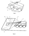
- Figure 1 shows us a vehicle 1 illustrative of a vehicle that can evolve in any terrain. It is here, for example represented while driving on a terrain element 5.
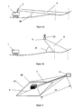
- FIG. 2 shows an overview of the device in its scope of use.
- the vehicle 1 evolves on the terrain 5.
- the acquisition means 2 of the three-dimensional geometry of the terrain 5 is mounted integral with the vehicle body, preferably on a high point, in order to increase the angle of incidence of the vehicle. acquisition.
- the geometry of the terrain 5 located in front of the vehicle 1 and that the latter will potentially travel in a moment to come, is acquired by the acquisition means 2 or three-dimensional imager.
- This acquisition means 2 of the terrain geometry 5 has a field of view 4 in the direction of the progression of the vehicle 1.
- FIG. 3b illustrates an alternative configuration, in which the acquisition means 2 is advantageously installed on a drone 21, separated from the vehicle 1
- the movement of the drone independent of that of the vehicle 1, allows advantageous positioning of the viewing point of the acquisition means, to better "see” the terrain 5 in certain situations.
- the drone 21 advantageously moves by preceding the vehicle 1 in order to collect information on the terrain 5.
- the mode of locomotion of the drone 21 can be arbitrary.
- An aerial version is advantageously retained.
- Figure 3b shows comparatively in FIG. 3a, that for the same field of view 4, the advanced position of the drone 21 makes it possible to "see” the terrain 5 with a greater angle of incidence.
- the quality of the acquisition increases with the angle of incidence 39, this is an interesting advantage.
- the acquisition means 2 comprises a beam 3.
- This beam 3 is linear, concentrated and points in a controllable direction. It allows by a principle known to those skilled in the art to measure the distance 41 between its source, here the acquisition means 2, an obstacle 40 coming, if necessary, to intervene in front of said beam 3.
- the beam 3 consists of a concentrated wave which is reflected by the terrain 5 in general and by the obstacle 40 in particular. This wave is advantageously a laser beam.
- the acquisition means is advantageously oriented slightly downwards, so that the beam 3 encounters the terrain 5. This makes it possible to know, in the direction pointed by the beam 3, the distance between the terrain 5 and the vehicle 1.
- the beam direction 3 scan an angular sweep in two directions, preferably substantially perpendicular, for example in site and in bearing, and by measuring the distance 41 to the ground 5 for each site angle and deposit angle value, an area of substantially rectangular terrain 5 is mapped.
- this zone is a spherical sector, and one considers its intersection, substantially rectangular, with the surface of the ground.
- the field of view 4 designates the total area that the acquisition means 2 can acquire, when the scanning site and field is used to the maximum of its capabilities in extent.
- a distance d is measured for each angle of site s and for each bearing angle g.
- a geometrical mapping of the terrain 5 is thus obtained in the field of view 4 in the form of a set of triplets (s, g, d).
- the terrain profile is thus obtained in spherical coordinates, in a coordinate system centered on the acquisition means 2.
- the beam 3 is too high. If the incidence 39 is negative or zero, relative to the ground level, the beam encounters no obstacle, is not reflected and no distance measurement 41 can be obtained. Similarly if the incidence 39 is too small, the beam 3 can meet the terrain 5 but do not cause sufficient reflection to allow a measurement.
- the resolution of such an acquisition is defined by the number of distance measurements 41 made in the field of view 4.
- This frequency is characteristic of the acquisition means 2. It is determined by the type of wave used and by the means making it possible to make the beam 3 perform angular scans. It can not, in the current state of technology, be increased.
- the current three-dimensional imagers make it possible to perform the order of one hundred thousand measurements of distances per second (100 kHz). It is considered that the overall acquisition time and change-point processing time of a point is less than 30 micro seconds.
- a minimum resolution is necessary to detect in the field 5 the smallest obstacle 40 whose size is sufficient to endanger the vehicle 1, the equipment it embarks or its crew. Such an obstacle 40 must be detected by the device, a smaller obstacle that can be ignored. It is assumed, as an illustration that the vehicle 1, its running gear and its suspension, allow to ignore an obstacle of 10 cm extension, regardless of the speed of evolution. This makes it possible to consider a resolution in the field comprising at least one point acquisition area of 10 X 10 cm.
- An attempt is made to reach an objective speed of evolution of the vehicle 1, set according to the operational objectives, as an indication, at a value of the order of 10 m / s. It is necessary to acquire and analyze the terrain 5 before the vehicle 1 is traveling through it.
- One of the principles of the invention is to determine certain characteristics of the terrain 5, in front of the vehicle 1, before the latter goes through it.
- the solution adopted by the invention consists in reducing the acquisition zone to a part 6 of the field of view 4, as illustrated in FIG. 2.
- This part 6 delimits a plate 15 in the field 5.
- This part 6 of the field of view 4 is determined by reducing the extent of scanning by the beam 3 in site and / or in the field.
- the plate 15 acquired by the means 2 is necessarily beyond the stopping distance 11.
- the acquisition and the analysis which follows it require a certain amount of time. 20.
- the vehicle 1 continues its movement and travels a certain distance. This additional distance is equal to the integral of the instantaneous speed of the vehicle 1 over the time interval necessary for the treatment. This distance is increased by a magnitude that is called distance margin 12.
- This margin of distance 12 plusante can, for example, be taken equal to the product of the maximum speed of the vehicle 22 by the processing time 20. This value constitutes a maximum increase.
- the optimization of this margin of distance 12, by reducing it to a minimum makes it possible to optimize the moment of the beginning of acquisition of the plate 15, by delaying it as much as possible.
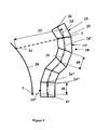
- Figure 7 supports the detailed description of the construction of a new plate 15 prior to its acquisition by means 2.
- a plate 15 is a portion of land 5. It is a three-dimensional surface. It is limited by four segments 7,8,9,10. A first segment 7 connecting a point 43 to a point 44 limits the plate 15 on the side close to the vehicle 1. A second segment 8 connecting a point 45 to a point 46 limits the plate 15 on the remote side of the vehicle 1. Two lateral segments 9 , Complete the plate 15 by respectively connecting 43 to 45 and 44 to 46.
- the previous plate 15 ' is bounded by a first near segment 7', a second remote segment 8 'and two lateral segments 9' and 10 '.
- the first near segment 7 of the new plate 15 is advantageously chosen to be merged with the remote segment 8 'of the previous plate 15' acquired and previously treated with the new plate 15.
- Such a construction guarantees that the previously mentioned constraint, related to the distance stop 11, increased by the safety margin 12, is satisfied. In fact, this distance, regardless of the weighting retained, remains smaller than the length of a plate 15, this length being equal to the product of the maximum speed 22 of the vehicle 1 by the processing time 20 of a plate 15, 15 '. The segment 7 is thus located beyond the distance 11 increased by the safety margin 12.
- the second remote segment 8 is positioned relative to the first near segment 7 in the following manner, illustrated in FIG. 7. From the middle point of the first near segment 7, and making an overall angle 27 with a middle segment 24 'of the previous plate 15 ', a medial segment 24 is drawn. This medial segment 24 has a length equal to the product of the treatment time 20 required for acquisition and treatment of the new plate 15, by the maximum speed 22 of the vehicle 1 considered. The point 25 is the first end of the middle segment 24.
- the second remote segment 8 is perpendicular to the middle segment 24 and its middle coincides with the point 26, second end of the middle segment 24.
- the determination of the overall orientation angle of the middle segment 24, which determines the orientation of the new plate 15 is achieved by algebraically adding a control angle 28 and a correction angle 29.
- FIG. 8 The determination of the control angle 28 is illustrated in FIG. 8.
- the last plate 15 'acquired and processed The segment connecting point 43 to point 44 of this figure is the second segment 8 'remote from this plate 15' and also the first segment 7 near the new plate 15 that is to be determined.
- the steering control of the vehicle 1 is given by the operator by a turning radius.
- This command by the turning radius can be represented, in the vehicle mark, by a control circle arc 30.
- This control circular arc 30 starts on the vehicle 1, is tangent to the longitudinal axis of said vehicle 1 and has a radius equal to the radius of turn commanded.
- This arc 30 intersects the first near segment 7 of the new plate 15 at a point of intersection 31.
- the tangent 32 to the control arc 30 at the point of intersection 31 is with the middle segment 24 'of the previous plate 15 'a control angle 28.
- the determination of the control angle 28 is advantageously effected by filtering the result of the calculation over a horizon substantially equal to one second in time.
- this control angle 28 it may appear, in practice, a divergence between the position of the plates 15,15 'and the actual position of the vehicle 1. To correct this divergence, we apply a global angle 27 which is the sum of the control angle 28 and a correction angle 29.
- This correction angle 29 is determined by the product of a correction constant 38 by a measured correction distance 33, as illustrated in FIG. 9, between a midpoint of the first near segment 7 of the new plate 15 (which is also the first end of the middle segment 24), and a control point 34.
- a projection point 47 is determined by projecting the position of the vehicle 1 on said broken line 35. This projection point 47 is the point of the line 35 closest to the vehicle 1. A distance 37 measured along the broken line 35 between the projection point 47 and the midpoint of the middle segment 24 of the new plate 15 is determined.
- This distance 37 is equal to a distance 48 remaining to run on the plate 15 "closest to the vehicle 1, ie the distance between the projection point 47 and the second end 26" of the median segment 24 "to which the projection point belongs. 47, accumulated with the lengths 49 of the plates 15,15 ', 15 ", ... (or lengths of the middle segments 24,24', 24", ...) encountered to reach the point 25 of the new plate 15 along the broken line 35.
- the length 49 of one plate being identical to the length of the other plates
- the distance 37 is the distance 48 plus n times the length 49 of a plate, n being the number of plates separating the plate 15 "nearest vehicle 1, the new plate 15.
- the control point 34 is located on the control circle arc 30 at a distance 36 from the vehicle 1, taken equal to the distance 37, measured along the control circle arc 30.
- the remote segment 8 of the new plate 15 is advantageously determined by using for the orientation of the plate 15 the overall angle 27 sum of the angle order 28 and correction angle 29.
- a limitation of the acquisition of the plate 15 is related to the measuring principle. Because of the need to obtain a distance measurement, to obtain a reflection of the beam 3 on the ground 5, it is necessary to direct the beam towards the ground 5 with minimal incidence.
- the incidence 39 of the beam 3 depends on the local orientation of the terrain where the beam 3 meets it.
- the incidence 39 also depends on the angle of elevation of the beam 3, which depends on the sweep angle of the beam as well as the orientation of the acquisition means 2 which can itself depend on the angle pitch and to a lesser extent the roll angle of the vehicle 1. If the incidence 39 becomes too small and therefore below a certain threshold, the distance measurement becomes impossible. This can lead to a limitation of the part 6 upwards, and thus of the plate 15 on its remote side 8.
- the plates 15 are acquired and analyzed continuously. When a previous plate 15 is acquired and analyzed, it is possible to start the acquisition and analysis of the next new plate. This is done in such a way that the assembly of the plates constitutes a continuous channel 18, the whole surface of which is the subject of analysis.
- the plate 15 is effectively limited between the segments 7 and 8.
- shadow zone 42 there appears a dead zone 42 where no analysis is possible and where continuity of the channel can not be ensured. This can be taken into account to remove unnecessary acquisition points.
- the necessary treatment of the discontinuity of the channel is ensured by a slowing down of the vehicle, giving it the margin of distance and the time to resume the acquisition and analysis of the plate 15, while hoping for a disappearance of the zone of shadow.
- the slowdown is automatically introduced by the temporary assignment of a maximum crossing speed of zero for the plate 15 considered.
- This plate 15 can not be analyzed is declared temporarily impassable in order to secure the vehicle during a re-analysis or improvement of the situation.
- FIG. 5a the vehicle 1 is far from the zone and the analysis by means 2 reveals a blind zone 42. In the absence of information, doubt is allowed and the adopted strategy remains cautious awaiting more information.
- Another difficulty lies in the fact that the driver remains free to act on the direction of the vehicle 1. This is even more amplified than the speed and therefore the stopping distance 11 which determines the distance at which the terrain must be acquired. 5, increase, and that the plate 15 on which the acquisition is made, away from the vehicle 1.
- the width of a plate 15, advantageously taken to be identical for all the plates 15, is determined by the capabilities of the three-dimensional imager 2 in terms of resolution. However, it is necessary for the width of the plate 15 to be a multiple of, or n times, the width of the vehicle 1. The larger the vehicle, the larger the vehicle is likely to be on the channel analyzed, despite the variations in control of the vehicle. direction. If the capacity of the imager makes it possible to increase n, it becomes possible to increase the maximum speed of evolution.
- Said available width for a plate 15 is distributed in two equal parts around the center determined by the point 26, second end of the middle segment 24, which determines the position of the remote segment 8 of the new plate 15.
- the acquisition of a field plate 5 provides a geometric three-dimensional model or digital model of local terrain.
- this digital terrain model corresponding to a plate 15 a shape analysis is carried out which is intended to determine a maximum crossing speed 16 at which the vehicle can roll on said plate 15.
- This maximum crossing speed 16 is the highest speed at which the field plate 5 can be traversed safely.
- This analysis can be done according to several methods.
- a first method consists in simulating the running of a possibly simplified model of the vehicle 1 on the digital terrain model of the analyzed plate.
- the speed used in this simulation is gradually increased, until a given threshold of a criterion is reached.
- This criterion incorporates, advantageously, notions of stability of the vehicle, notions of comfort limit as felt by the crew, the onboard equipment or the vehicle itself.
- An example of a quantitative comfort limit is the use of the travel of a suspension element. Beyond a certain threshold value, and in particular the attainment of a stop, a movement of a suspension element is indicative of too much acceleration to remain comfortable.
- a second method consists of identifying the roughness of the terrain 5 on the digital terrain model of the plate 15, and estimating the possibility of evolution of the vehicle 1, from a pre-established table of correspondence between roughness and speed.
- the identification of the roughness can, for example, be carried out by frequency analysis of the spectral power density type of the digital terrain model of the plate 15.
- the correspondence table can be determined by real test or in simulation by performing running of a similar vehicle on areas of given canonical roughness and determining the maximum speed not causing the exceeding of a fixed threshold, where appropriate associated with a criterion of discomfort or instability.
- a third method corresponds to an analytical treatment of the plate 15 by considering its shape.
- the principle is to break down the geometric shape of the digital terrain model of the plate 15 into a set of elementary local obstacles corresponding respectively to a step, a break of slope and a curtain of the ground. For each of these typical obstacles, it has been determined in advance the maximum local speed of crossing said obstacle.
- This method has the advantage that it is intrinsically surface in that it can give a maximum crossing speed 16 for each zone of the plate 15 analyzed.
- the plate 15 is a three-dimensional surface. For the purposes of representation, this plate 15 is visualized by a quadrilateral 19. This quadrilateral 19 is determined as it projects on the contour of the plate 15 according to the point projection centered on the point of vision located at the apex of the cone corresponding to Part 6 of the field of view 4. This quadrilateral 19 is not necessarily plane and can be veiled in space.
- a second plate 15 After acquiring a first plate 15 ', a second plate 15 can be acquired.
- the plates are, as we saw in their construction, determined contiguous.
- Each plate 15 '(respectively 15) thus successively acquired is associated with a quadrilateral 19' (respectively 19).
- This carriage channel 18 is the zone on which an acquisition of the ground 5 and an analysis have been carried out.
- Figure 10 illustrates an example of channel 18 as it can be presented to the operator.
- a maximum crossing speed 16 was determined. From the current speed of the vehicle 1, is built a template of maximum speed of crossing 17, to arrive on the plate 15 with a compatible speed of the maximum speed of crossing 16 of the same plate 15. This speed template 17 is determined along the trajectory 14 of the vehicle 1 recursively taking into account the slope of the terrain and the available grip potential. The grip potential of the terrain is assumed to be known. It is possible to determine, depending on the vehicle 1, a maximum allowable deceleration without dangerously soliciting the potential for adhesion available. The determination of the adhesion potential is not the subject of this patent.
- a maximum crossing speed 16 (respectively 16') determined intrinsically according to the geometry of the plate is provided. Starting from the furthest plate 15, its maximum crossing speed 16 is known, going up on the trajectory 14, assuming that the course is at the maximum deceleration / acceleration, a new maximum crossing speed is determined for the plate 15 'previous. This new maximum crossing speed may be different from that 16 'previously determined by the geometric analysis of this previous plate 15'. The lowest value of these two maximum crossing speeds (intrinsically determined speed for the plate, and speed determined recursively along the trajectory) is kept for integrating it with the speed gauge 17. This is done from plate to plate. going up along the channel 18. The speed gauge 17 thus obtained is a curve giving a maximum crossing speed 16 at each point, along the path of the vehicle 1, compatible with the instantaneous speed of the vehicle 1, the acceleration / braking capabilities of said vehicle 1 and the terrain encountered over the entire channel 18 analyzed.
- the information is used to assist the choices of the (tele) pilot.
- the terrain analysis information 5 is presented to the pilot in graphic form, schematized by the graphical representation of the vehicular channel 18 in superposition of the terrain 5, as shown in FIG. 10.
- the pilot is free to control the speed of the vehicle as long as this speed remains lower than that of the template 17. If it tends to become larger than the template 17, an automatic control intervenes on the control of advance and the limit so that the speed remains at any moment lower than the template 17 and that the Vehicle 1 evolves at all times in safety.
- the channel 18, as a succession of the quadrilaterals 19 is displayed to be visible from the pilot.
- said video camera is advantageously located on the vehicle near the acquisition means 2 and advantageously has a near field of view, or including the field of view 4 of the acquisition means 2. It is then possible to display the channel 18 in superposition of the image field video 5, on the same viewing screen, after applying the appropriate benchmark change.
- the representation of the channel is limited as shown in FIG. 10 to the wireline pattern of the segments / sides of the quadrilaterals 19.
- a surface index can be used to bring out information in the surface of the quadrilateral, for example a color, a gray level or hatching, but this color remains transparent. This in order not to mask the image of the ground 5.
- the information of carossability is added to the ground, which it does not replace.
- Linear or surface-based over-shine or flash effects can be used to highlight a given quadrilateral 19.
- N + 1 different graphical representations to symbolize different states. It is thus possible to vary the representation of the lines used for the contours of each quadrilateral among: continuous line, dotted line, dashed line, etc. It is also possible to vary the surface of the quadrilateral with different colors, gray levels , hatching or any other texture. In all cases we maintain a certain transparency in order to leave free the perception of the real ground.
- a particular graphic representation is used to indicate an impassable quadrilateral, corresponding to a maximum crossing speed of zero.
- the other N graphic representations may for example each be associated with a portion of N of the total range of accessible speed to the vehicle 1. This total range of speed corresponds to the range from zero speed to the maximum speed of the vehicle. This range is partitioned in N under speed ranges.
- Each sub-range is associated, for the graphical representation, a linear or areal graphic symbolization.
- a quadrilateral 19 corresponding to a delicate plate 15 can be, for example, visualized by a particular graphical representation corresponding to that associated with non-passability or another graphic representation dedicated to this temporary state, as long as its passability does not exist. is not established.
- the pilot is warned by the adapted graphic representation, the plate not yet analyzed is assigned, at least temporarily, a maximum crossing speed of 16 zero.
- the speed mask is automatically reduced. Consequently, this leads to a vehicle approach 1 at a lower speed. This provides additional time to repeat the acquisition and / or analysis of the plate. This closer analysis (see Figure 5b) is more likely to succeed.
- the pilot is warned by the display which returns to normal.
- the maximum crossing speed 16 and the jig 17 are recalculated.
- Another alternative is to allow the pilot to validate, under his control, a plate 15, for which he stops the acquisition and analysis and lifts the limitation.
- the pilot under his responsibility, resumes in this case the hand on the automatic speed limitation.
- the acquisition of a plate 15 is ideally carried out in an instant.
- the double angular sweeping of the beam 3 necessary to traverse the plate 15 and the time of each measurement of distance on each point takes a certain time. During this time the vehicle continues moving. This displacement is done off-road, the orientation of the vehicle is constantly changed. If the acquisition means 2 is directly integral with the vehicle 1, this has the effect of deflecting the beam 3, which no longer targets the point of the desired plate 15.
- These changes in orientation of the beam 3, relative to the sweeping time at high speeds that we are trying to maintain lead to plate acquisition deformations that are too great to allow exploitation. To obtain an exploitable result, it is necessary to stabilize the acquisition.
- the complete cycle time of plate acquisition and complete processing of its drivability analysis is reasonably one second, to be compatible with other system constraints.
- This complete cycle comprises, in a first step, an acquisition time followed by a time dedicated to the analysis calculations of the acquired plate.
- the acquired plate is reasonably sized to be 10 m by 10 m square. Given an indicative resolution of the order of 10 cm, this acquisition requires 10000 points.
- the acquisition time of a point being less than or equal to 30 micro seconds, the acquisition of a plate 15 requires about 0.3 seconds.
- the acquisition means 2 is not used during the treatment phase, ie for 0.7 seconds.
- the invention takes advantage of this availability to perform a rough pre-acquisition of the new plate 15.
- the characteristic elements of the plate 15 such as the slope and the average slope. Even a rough preview of the shape of the plate 15 makes it possible to estimate the incidence of the beam 3 during the distance measurement. This makes it possible to determine zones that will require a greater or lesser density of measurement points during the final definitive acquisition. It is thus possible to determine for the plate 15, before its final acquisition, an optimal distribution of acquisition points such that these acquisition points have a distance between them, measured on the ground, also called spatial pitch, constant. This spatial step is advantageously less than or equal to the resolution set to detect a potentially dangerous obstacle. This makes it possible to optimize the final acquisition of the plate 15 by controlling the scanning of the acquisition means 2 as a function of this optimum distribution of the acquisition points.
Abstract
Description
Le secteur technique de la présente invention est celui de l'assistance au pilotage des véhicules.The technical sector of the present invention is that of assisting the piloting of vehicles.
Jusqu'à ce jour, le pilotage d'un véhicule en tout terrain s'effectue sans assistance. Le pilote estime les difficultés du terrain, sa carrossabilité, sa franchissabilité en s'aidant uniquement de sa vue et de son expérience. Il dispose d'une perception du relief par l'intermédiaire de sa vision binoculaire, ainsi que d'autres indices de profondeur liés au déplacement, aux ombres, etc., tous obtenus par la vue et les traitements effectués par le cerveau. Il est aidé dans cette tâche perceptive par son expérience, son entraînement et éventuellement par sa connaissance préalable du relief ou de la nature du terrain. Malgré cela, il est rare qu'un pilote utilise une part importante des capacités intrinsèques, notamment en vitesse, de son véhicule. Cette auto-limitation, se traduisant par des vitesses faibles, est d'autant plus importante que le pilote est peu expérimenté. La vitesse peut se réduire encore davantage lorsque, dans le cas d'un véhicule télépiloté, le (télé-)pilote déporté à distance et débarqué du véhicule, ne disposant pas d'une perception directe et complète est incité à la prudence.Until now, driving a vehicle in any terrain is done without assistance. The pilot estimates the difficulties of the terrain, its carability, its passability with the help of only its view and experience. He has a perception of relief through his binocular vision, as well as other depths related to displacement, shadows, etc., all obtained by the sight and treatments performed by the brain. He is helped in this perceptual task by his experience, his training and possibly by his prior knowledge of the terrain or the nature of the terrain. Despite this, it is rare for a pilot to use a large part of the intrinsic capacities, notably in speed, of his vehicle. This self-limitation, resulting in low speeds, is even more important than the pilot is inexperienced. The speed can be further reduced when, in the case of an unmanned vehicle, the (remote) pilot remotely deported and disembarked from the vehicle, not having a direct and complete perception is urged caution.
On connaît des moyens d'acquérir une cartographie tridimensionnelle du terrain devant le véhicule avec une résolution compatible des besoins de détection permettant d'assurer la sécurité du véhicule, du matériel et des personnels embarqués. Une anomalie du terrain pourra être ignorée, et donc être invisible du moyen d'acquisition du terrain, si son étendue géométrique reste inférieure à un seuil. Ce seuil est déterminable en fonction du véhicule, de ses suspensions et de la capacité de l'ensemble, ainsi que du matériel et des personnels embarqués, à supporter sans dommage une accélération provoquée par le roulage sur ladite anomalie à une vitesse donnée.Means are known to acquire a three-dimensional mapping of the terrain in front of the vehicle with a compatible resolution of the detection requirements to ensure the safety of the vehicle, equipment and personnel on board. An anomaly of the terrain may be ignored, and therefore be invisible from the terrain acquisition means, if its geometric extent remains below a threshold. This threshold is determinable depending on the vehicle, its suspensions and the capacity of the assembly, as well as the equipment and personnel on board, to withstand without damage an acceleration caused by taxiing on said anomaly at a given speed.
Ces moyens d'acquisition du terrain encore appelés imageurs tridimensionnels permettent une acquisition dans un champ de vision et à une fréquence de rafraîchissement comparable à celui, par exemple, d'une caméra vidéo du type de celles utilisées en télépilotage. Cependant l'utilisation de tels imageurs tridimensionnels pour fournir au (télé- )pilote une information pertinente lui permettant d'apprécier les possibilités d'évolution dans la direction qu'il désire prendre ou pour déterminer automatiquement la meilleure trajectoire de cheminement pour le véhicule rencontre des limitations. Si l'on analyse la totalité du champ de vision, le temps nécessaire à l'acquisition du terrain, puis aux traitements permettant de déterminer les paramètres de la carossabilité n'est pas compatible avec les besoins d'information utile, à la vitesse d'évolution du véhicule. Si a contrario, l'analyse est limitée à une zone partielle du champ de vision complet, on ne sait pas choisir la zone sur laquelle il est intéressant de concentrer l'analyse. Il est en effet difficile de connaître la future zone où va rouler le véhicule, tout en conservant au pilote sa liberté de commande de direction et de choix du parcours emprunté par son véhicule.These terrain acquisition means, also called three-dimensional imagers, allow acquisition in a field of view and at a refresh rate comparable to that of, for example, a video camera of the type those used in telepiloting. However, the use of such three-dimensional imagers to provide the (tele-) pilot with relevant information enabling him to appreciate the possibilities of evolution in the direction he wishes to take or to automatically determine the best path for the vehicle to encounter. limitations. If the entire field of view is analyzed, the time required for acquisition of the land, and then the treatments to determine the parameters of the carossability is not compatible with the needs of useful information, at the speed of evolution of the vehicle. If on the contrary, the analysis is limited to a partial zone of the complete field of view, it is not possible to choose the zone on which it is interesting to concentrate the analysis. It is indeed difficult to know the future area where the vehicle will roll, while maintaining the driver's freedom of direction and choice of the route taken by his vehicle.
Le but de l'invention est de proposer un dispositif permettant l'acquisition du terrain suivi par un véhicule de manière rapide.The object of the invention is to provide a device for acquiring the terrain followed by a vehicle in a fast manner.
L'invention a donc pour objet un dispositif d'assistance au pilotage en tout terrain d'un véhicule comprenant un moyen d'acquisition de la géométrie du terrain utilisant un faisceau permettant une mesure de distance dans l'axe dudit faisceau, auquel est imposé un pilotage angulaire selon deux directions sensiblement perpendiculaires, dans un champ de vision situé devant le véhicule, caractérisé en ce que le moyen d'acquisition est relié au véhicule et est configuré pour effectuer une acquisition partielle limitée à une plaque de terrain correspondant à une partie du champ de vision.The subject of the invention is therefore a device for assisting the piloting of a vehicle in any terrain, comprising a means for acquiring the geometry of the terrain using a beam allowing a measurement of distance in the axis of the beam, to which is imposed an angular steering along two substantially perpendicular directions, in a field of vision in front of the vehicle, characterized in that the acquisition means is connected to the vehicle and is configured to perform a partial acquisition limited to a field plate corresponding to a part of the field of vision.
Le moyen d'acquisition peut être configuré pour effectuer une nouvelle plaque après avoir acquis une plaque précédente.The acquisition means may be configured to make a new plate after acquiring a previous plate.
Avantageusement, le moyen d'acquisition peut être fixé sur le véhicule ou sur un drone mobile indépendamment du véhicule.Advantageously, the acquisition means can be fixed on the vehicle or on a mobile drone independently of the vehicle.
Une plaque est limitée d'un côté proche du véhicule par un premier segment proche, d'un côté distant du véhicule par un second segment distant et latéralement par deux segments reliant les extrémités desdits premier et second segments et que ladite plaque comprend un segment médian.A plate is limited on one side close to the vehicle by a first segment near, on a side remote from the vehicle by a second segment remote and laterally by two segments connecting the ends of said first and second segments and said plate comprises a middle segment.
Avantageusement, le premier segment proche d'une nouvelle plaque est confondu avec le second segment distant d'une plaque précédente.Advantageously, the first segment near a new plate is coincident with the second segment remote from a previous plate.
Selon une caractéristique de l'invention, le segment médian d'une nouvelle plaque est perpendiculaire au second segment distant de ladite nouvelle plaque, et présente une longueur égale au produit de la vitesse maximale du véhicule par un temps de traitement nécessaire à l'acquisition et au traitement de la plaque, ledit segment médian comprenant une première extrémité et une seconde extrémité, la première extrémité est confondue avec le milieu du premier segment proche de la nouvelle plaque et la seconde extrémité est confondue avec le milieu du second segment distant de la nouvelle plaque.According to one characteristic of the invention, the median segment of a new plate is perpendicular to the second segment remote from said new plate, and has a length equal to the product of the maximum speed of the vehicle by a processing time necessary for the acquisition. and at the treatment of the plate, said medial segment comprising a first end and a second end, the first end coincides with the middle of the first segment near the new plate and the second end coincides with the middle of the second segment remote from the new plate.
Selon une autre caractéristique, le segment médian de la nouvelle plaque délimite un angle global avec le segment médian de la plaque précédente, l'angle global étant la somme d'un angle de commande et d'un angle de correction, le véhicule étant commandé en direction suivant un arc de cercle de commande passant par la position du véhicule tangent à l'axe du véhicule et de rayon égal au rayon de virage commandé .According to another characteristic, the median segment of the new plate delimits an overall angle with the median segment of the previous plate, the overall angle being the sum of a control angle and a correction angle, the vehicle being controlled in the direction following a control circle arc passing through the position of the vehicle tangential to the axis of the vehicle and of radius equal to the radius of controlled turn.
Avantageusement, l'angle de commande est égal à l'angle entre la tangente à l'arc de cercle de commande au point d'intersection entre ledit arc de cercle de commande et le premier segment proche de la nouvelle plaque, avec le segment médian de la plaque précédente.Advantageously, the control angle is equal to the angle between the tangent to the control arc of the circle at the point of intersection between said control circle arc and the first segment close to the new plate, with the median segment from the previous plate.
L'angle de commande est temporellement filtré sur un horizon sensiblement égal à une seconde.The control angle is temporally filtered over a horizon substantially equal to one second.
Avantageusement encore, l'angle de correction est égal à une constante de correction que multiplie une distance de correction, cette distance de correction étant mesurée en ligne droite entre un point de commande et la première extrémité du segment médian de la nouvelle plaque, ledit point de commande étant situé sur l'arc de cercle de commande à une distance du véhicule, mesurée le long dudit arc de cercle de commande, ladite distance étant égale à une distance mesurée entre ladite première extrémité (25) et un point de projection, cette distance étant mesurée le long d'une ligne brisée suivant les segments médians, le point de projection étant le point de ladite ligne brisée le plus proche du véhicule.Advantageously, the correction angle is equal to a correction constant multiplied by a correction distance, this correction distance being measured in a straight line between a control point and the first end of the median segment of the new plate, said point command being located on the control circle arc at a distance from the vehicle, measured along said control circle arc, said distance being equal to a distance measured between said first end (25) and a projection point, said distance being measured along a broken line according to the median segments, the projection point being the point of said broken line nearest the vehicle.
Au moins une pré-acquisition à maillage grossier d'une plaque est effectuée pour optimiser l'acquisition définitive ultérieure de ladite plaque pour déterminer la pente et le dévers moyen de la plaque, l'acquisition préalable permettant de déterminer une répartition à pas constant, des points d'acquisition sur la plaque, ladite répartition étant utilisée pour l'acquisition définitive.At least one coarse grid pre-acquisition of a plate is performed to optimize the subsequent final acquisition of said plate to determine the slope and the average cant of the plate, the prior acquisition to determine a constant pitch distribution, acquisition points on the plate, said distribution being used for the final acquisition.
La plaque est analysée pour déterminer une vitesse maximale de franchissement de ladite plaque.The plate is analyzed to determine a maximum speed of crossing said plate.
Selon une caractéristique, la vitesse maximale de franchissement est déterminée par une méthode temporelle simulant le roulage d'un modèle simplifié du véhicule sur la plaque en variant la vitesse dudit modèle jusqu'à dépassement d'un critère d'inconfort et/ou d'instabilité.According to one characteristic, the maximum crossing speed is determined by a temporal method simulating the running of a simplified model of the vehicle on the plate by varying the speed of said model until a criterion of discomfort and / or instability.
Selon une autre caractéristique, la vitesse maximale de franchissement est déterminée par une méthode fréquentielle déterminant la rugosité du terrain et lui faisant correspondre une vitesse maximale de franchissement par un tableau de correspondance pré-établi.According to another characteristic, the maximum speed of crossing is determined by a frequency method determining the roughness of the terrain and making it match a maximum speed of crossing by a pre-established correspondence table.
Selon encore une autre caractéristique, la vitesse maximale de franchissement est déterminée par une méthode spatiale consistant à découper la plaque en éléments de relief élémentaires auxquels sont respectivement associées des vitesses maximales de franchissement.According to yet another characteristic, the maximum crossing speed is determined by a spatial method of cutting the plate into elementary relief elements which are respectively associated with maximum crossing speeds.
Selon encore une autre caractéristique, la vitesse maximale de franchissement est déterminée par une méthode combinant les méthodes temporelle, fréquentielle, spatiale.According to yet another characteristic, the maximum crossing speed is determined by a method combining temporal, frequency and spatial methods.
Avantageusement, chaque plaque est visualisée par un quadrilatère, dont les segments des côtés se superposent avec les segments de la plaque.Advantageously, each plate is visualized by a quadrilateral, whose segments of the sides are superimposed with the segments of the plate.
Selon encore une caractéristique, un chenal est construit en assemblant bout à bout les quadrilatères issus des plaques.According to another characteristic, a channel is built by assembling the quadrilaterals from the plates end to end.
Selon encore une caractéristique, un gabarit de vitesse maximale de franchissement est construit de manière récursive en fonction de la vitesse maximale de franchissement déterminée pour chaque plaque du chenal garantissant que l'on pourra atteindre une plaque donnée à une vitesse inférieure à la vitesse maximale de franchissement de cette plaque.According to another characteristic, a maximum crossing speed jig is built recursively according to the maximum crossing speed determined for each channel plate ensuring that a given plate can be reached at a speed below the maximum speed of the crossing. crossing this plate.
Avantageusement, le gabarit de vitesse est tel que la décélération maximale, le long de ce gabarit, reste à tout instant inférieure au potentiel d'adhérence disponible.Advantageously, the speed mask is such that the maximum deceleration along this jig remains at all times less than the available adhesion potential.
Selon encore une caractéristique, le chenal constitué de la succession de quadrilatères est projeté en superposition du champ de vision du pilote.According to another characteristic, the channel consisting of the succession of quadrilaterals is projected in superposition of the pilot's field of vision.
Selon encore une caractéristique, le champ de vision est vu directement et la projection du chenal s'effectue en transparence sur une lame semi-réfléchissante intercalaire.According to another characteristic, the field of view is seen directly and the projection of the channel is effected in transparency on a semi-reflective plate intermediate.
Le champ de vision est vu sur un écran de visualisation et en ce que le chenal est projeté en transparence sur ledit écran de visualisation.The field of view is viewed on a display screen and in that the channel is projected transparently on said display screen.
Selon encore une caractéristique, la représentation graphique des quadrilatères utilise une symbolique graphique pour signifier qu'une plaque est infranchissable.According to another characteristic, the graphical representation of the quadrilaterals uses a graphic symbolism to signify that a plate is impassable.
Selon encore une caractéristique, la représentation graphique des quadrilatères utilise N symboliques graphiques, pour signifier qu'une plaque est franchissable à une vitesse appartenant à l'une des N zones partageant la plage totale de vitesse.According to another characteristic, the graphical representation of the quadrilaterals uses symbolic N symbols, to signify that a plate is passable at a speed belonging to one of the N zones sharing the total speed range.
Un avantage du dispositif selon l'invention est de permettre une analyse de la carrossabilité du terrain à partir de sa géométrie acquise en temps réel.An advantage of the device according to the invention is to enable an analysis of the terrain's terrain capability from its acquired geometry in real time.
Un autre avantage du dispositif objet de la présente invention est de permettre d'acquérir et d'analyser le terrain en temps réel à des vitesses de progression du véhicule élevées.Another advantage of the device that is the subject of the present invention is that it makes it possible to acquire and analyze the terrain in real time at high vehicle progression speeds.
Un autre avantage du dispositif objet de la présente invention est de permettre d'augmenter sensiblement la vitesse de progression en sécurité, tant pour un pilote embarqué que pour un télé-pilote.Another advantage of the device that is the subject of the present invention is that it makes it possible to substantially increase the speed of progression safely, for a pilot as well. embedded only for a tele-pilot.
Un autre avantage du dispositif selon l'invention est de fournir des informations utiles au (télé-)pilote.Another advantage of the device according to the invention is to provide useful information to (tele-) pilot.
Un autre avantage du dispositif selon l'invention est de permettre d'afficher ces informations en superposition avec le champ de vision habituel du (télé)pilote.Another advantage of the device according to the invention is to make it possible to display this information in superposition with the usual field of view of the (tele) pilot.
Un autre avantage du dispositif selon l'invention est d'indiquer au (télé)pilote un chenal dans lequel il sait qu'il peut progresser et dans lequel il sait que sa vitesse est limitée automatiquement afin d'éviter de mettre le véhicule, son matériel ou son personnel embarqués en danger.Another advantage of the device according to the invention is to indicate to the (tele) pilot a channel in which he knows he can progress and in which he knows that his speed is limited automatically to avoid putting the vehicle, its equipment or its staff on board.
Un autre avantage du dispositif selon l'invention est de permettre d'utiliser un moyen d'acquisition de la géométrie tridimensionnelle du terrain, du type de ceux existant actuellement dans le commerce.Another advantage of the device according to the invention is that it makes it possible to use a means for acquiring the three-dimensional geometry of the terrain, of the type currently existing commercially.
D'autres caractéristiques, détails et avantages de l'invention ressortiront plus clairement de la description détaillée donnée ci-après à titre indicatif en relation avec des dessins sur lesquels :
- la figure 1 présente un véhicule équipé du dispositif, en cours d'évolution sur un terrain accidenté,
- la figure 2 illustre l'utilisation du dispositif en relation avec le terrain, et l'acquisition partielle réduite à une partie du champ de vision,
- la figure 3a illustre une configuration avec le moyen d'acquisition monté sur le véhicule,
- la figure 3b illustre une configuration avec le moyen d'acquisition monté sur un drone,
- la figure 4 illustre le principe du moyen d'acquisition,
- la figure 5a illustre la notion de zone aveugle ou morte et la perte de qualité de l'acquisition à distance,
- la figure 5b illustre l'amélioration de la qualité de l'acquisition obtenue avec la diminution de la distance,
- la figure 6 introduit les distances de freinage et de sécurité,
- la figure 7 précise la construction d'une nouvelle plaque,
- la figure 8 illustre la définition de l'angle de commande,
- la figure 9 illustre la définition de l'angle de correction,
- la figure 10 illustre le chenal carrossable tel que présenté au (télé-)pilote en superposition de son champ de vision,
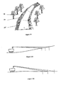
- les figures 11a et 11b illustrent l'influence de la pente sur la résolution de l'acquisition.
- FIG. 1 shows a vehicle equipped with the device, in progress on a rough terrain,
- FIG. 2 illustrates the use of the device in relation to the field, and the partial acquisition reduced to a part of the field of view,
- FIG. 3a illustrates a configuration with the acquisition means mounted on the vehicle,
- FIG. 3b illustrates a configuration with the acquisition means mounted on a drone,
- FIG. 4 illustrates the principle of the acquisition means,
- FIG. 5a illustrates the notion of blind or dead zone and the loss of quality of the remote acquisition,
- FIG. 5b illustrates the improvement of the quality of the acquisition obtained with the decrease of the distance,
- Figure 6 introduces the braking and safety distances,
- Figure 7 shows the construction of a new plate,
- FIG. 8 illustrates the definition of the control angle,
- FIG. 9 illustrates the definition of the correction angle,
- FIG. 10 illustrates the vehicular channel as presented to the (tel-) pilot superimposed on his field of vision,
- Figures 11a and 11b illustrate the influence of the slope on the resolution of the acquisition.
La figure 1 nous montre un véhicule 1 illustratif d'un véhicule pouvant évoluer en tout terrain. Il est ici, par exemple représenté en cours de roulage sur un élément du terrain 5.Figure 1 shows us a
La figure 2 présente une vue d'ensemble du dispositif dans son cadre d'utilisation. Le véhicule 1 évolue sur le terrain 5. Le moyen d'acquisition 2 de la géométrie tridimensionnelle du terrain 5 est monté solidaire de la caisse du véhicule, avantageusement sur un point haut, afin d'augmenter l'angle d'incidence de l'acquisition. La géométrie du terrain 5 situé devant le véhicule 1 et que ce dernier va potentiellement parcourir dans un instant à venir, est acquise par le moyen d'acquisition 2 ou imageur tri-dimensionnel. Ce moyen d'acquisition 2 de la géométrie du terrain 5 dispose d'un champ de vision 4 dans la direction de la progression du véhicule 1.Figure 2 shows an overview of the device in its scope of use. The
Comme illustré par la figure 3a, Le moyen d'acquisition 2 peut être installé directement sur le véhicule 1. La figure 3b illustre une configuration alternative, dans laquelle le moyen d'acquisition 2 est avantageusement installé sur un drone 21, séparé du véhicule 1. Le déplacement du drone, indépendant de celui du véhicule 1, autorise un positionnement avantageux du point de vision du moyen d'acquisition, permettant de mieux « voir » le terrain 5 dans certaines situations. Le drone 21 se déplace avantageusement en précédant le véhicule 1 afin de recueillir des informations sur le terrain 5. Le mode de locomotion du drone 21 peut être quelconque. Une version aérienne est avantageusement retenue. La figure 3b montre comparativement à la figure 3a, que pour un même champ de vision 4, la position avancée du drone 21, permet de « voir » le terrain 5 avec un angle d'incidence 39 plus important. La qualité de l'acquisition augmente avec l'angle d'incidence 39, ceci constitue un avantage intéressant.As illustrated in FIG. 3a, the acquisition means 2 can be installed directly on the
Le principe de l'acquisition est illustré par la figure 4. Le moyen d'acquisition 2 comprend un faisceau 3. Ce faisceau 3 est linéaire, concentré et pointe dans une direction commandable. Il permet par un principe connu de l'homme de l'art de mesurer la distance 41 séparant sa source, ici le moyen d'acquisition 2, d'un obstacle 40 venant, le cas échéant, s'interposer devant ledit faisceau 3. Le faisceau 3 est constitué d'une onde concentrée qui est réfléchie par le terrain 5 en général et par l'obstacle 40 en particulier. Cette onde est avantageusement un faisceau laser. Le moyen d'acquisition est avantageusement orienté légèrement vers le bas, afin que le faisceau 3 rencontre le terrain 5. Ceci permet de connaître, dans la direction pointée par le faisceau 3, la distance entre le terrain 5 et le véhicule 1.The principle of the acquisition is illustrated in FIG. 4. The acquisition means 2 comprises a
En faisant parcourir à la direction du faisceau 3 un balayage angulaire selon deux directions, avantageusement sensiblement perpendiculaires, par exemple en site et en gisement, et en mesurant la distance 41 au terrain 5 pour chaque valeur d'angle site et d'angle gisement, on cartographie une zone du terrain 5 sensiblement rectangulaire. Pour être exact, cette zone est un secteur sphérique, et l'on considère son intersection, sensiblement rectangulaire, avec la surface du terrain. Le champ de vision 4 désigne la zone totale que peut acquérir le moyen d'acquisition 2, lorsque le balayage en site et en gisement est utilisé au maximum de ses capacités en étendue. Pour chaque angle de site s et pour chaque angle de gisement g, on mesure une distance d. On obtient ainsi une cartographie géométrique du terrain 5, dans le champ de vision 4, sous forme d'un ensemble de triplets (s, g, d). Le profil du terrain est ainsi obtenu en coordonnées sphériques, dans un repère centré sur le moyen d'acquisition 2.By making the
On voit sur la figure 5a, une limitation du principe de mesure. En cas de présence d'une partie de terrain située derrière un élément de relief saillant, le faisceau 3 ne peut rencontrer une partie du terrain et cette partie 42, dénommée zone d'ombre 42, zone morte ou zone aveugle, n'apparaît pas sur la cartographie du terrain 5.We see in Figure 5a, a limitation of the measuring principle. In the event of the presence of a part of ground situated behind a protruding relief element, the
Il en est de même lorsque le faisceau 3 vise trop haut. Si l'incidence 39 est négative ou nulle, par rapport au niveau du sol, le faisceau ne rencontre aucun obstacle, n'est pas réfléchi et aucune mesure de distance 41 ne peut être obtenue. De manière similaire si l'incidence 39 est trop faible, le faisceau 3 peut rencontrer le terrain 5 mais ne pas provoquer une réflexion suffisante pour permettre une mesure.It is the same when the
La résolution d'une telle acquisition, est définie par le nombre de mesures de distance 41 effectuées dans le champ de vision 4. La durée d'une mesure de distance 41 ou, ce qui est équivalent, la fréquence maximale des mesures, limite cette résolution. Cette fréquence est caractéristique du moyen d'acquisition 2. Elle est déterminée par le type d'onde utilisée et par les moyens permettant de faire effectuer au faisceau 3 les balayages angulaires. Elle ne peut, dans l'état actuel de la technologie, pas être augmentée. Les imageurs tri-dimensionnels actuels permettent d'effectuer de l'ordre de cent mille mesures de distances par seconde (100 khertz). On considère que le temps global d'acquisition et de traitement de changement de repère d'un point est inférieur à 30 micro secondes.The resolution of such an acquisition is defined by the number of
Une résolution minimale est nécessaire pour détecter sur le terrain 5 le plus petit obstacle 40 dont la taille est suffisante pour mettre en danger le véhicule 1, le matériel qu'il embarque ou son équipage. Un tel obstacle 40 doit être détecté par le dispositif, un obstacle plus petit pouvant être ignoré. On suppose, à titre illustratif que le véhicule 1, son train de roulement et sa suspension, permettent d'ignorer un obstacle de 10 cm d'extension, quelle que soit la vitesse d'évolution. Ceci permet de considérer une résolution sur le terrain comprenant au moins un point d'acquisition par zone de 10 X 10 cm.A minimum resolution is necessary to detect in the
On tente d'atteindre une vitesse objective d'évolution du véhicule 1, fixée en fonction des objectifs opérationnels, à titre indicatif, à une valeur de l'ordre de 10 m/s. Il est nécessaire d'acquérir et d'analyser le terrain 5 avant que le véhicule 1 ne le parcourt.An attempt is made to reach an objective speed of evolution of the
Une solution pourrait consister à acquérir et analyser le terrain 5 très loin du véhicule afin de disposer de temps. Ceci est limité par plusieurs facteurs :
- la mesure de distance par le faisceau 3 a une limite de portée,
- plus la mesure s'effectue loin et plus l'incidence du faisceau 3 avec le
terrain 5 est faible et tend à rendre la mesure impossible, - plus l'acquisition s'effectue loin et plus il faudrait analyser un terrain large compte-tenu des possibilités de changement de direction du véhicule,
- plus l'acquisition s'effectue loin et plus la résolution est faible : une même variation d'angle site ou gisement correspondant à une plus grande étendue de terrain,
- plus l'acquisition s'effectue loin et plus le risque de zone d'ombre ou masquage est important. La coupure du faisceau par un obstacle saillant proche rend le moyen d'acquisition aveugle sur le terrain situé au-delà dudit obstacle saillant,
- plus l'acquisition s'effectue loin et plus l'imprécision sur la mesure des angles de balayage se rapproche de l'ordre de grandeur de la résolution angulaire.
- the distance measurement by the
beam 3 has a range limit, - the further away the measurement is, the lower the incidence of the
beam 3 with theterrain 5 is and makes the measurement impossible, - the more the acquisition takes place far and the more it would be necessary to analyze a wide field considering the possibilities of change of direction of the vehicle,
- the further the acquisition takes place, the lower the resolution: the same variation of site or deposit angle corresponding to a larger area of land,
- the further the acquisition takes place, the greater the risk of shadow zone or masking. Cutting the beam by a near projecting obstacle makes the acquisition means blind on the ground situated beyond said projecting obstacle,
- the further the acquisition takes place, the more inaccurate the measurement of the scanning angles is to the order of magnitude of the angular resolution.
L'un des principes de l'invention est de déterminer certaines caractéristiques du terrain 5, à l'avant du véhicule 1, avant que ce dernier ne le parcourt.One of the principles of the invention is to determine certain characteristics of the
Compte tenu de l'adhérence et du profil du terrain 5, une certaine accélération/décélération maximale est possible sans perte d'adhérence. Compte tenu de cette décélération maximale admissible, des possibilités de freinage du véhicule 1 et de sa vitesse instantanée, il est possible de déterminer une distance d'arrêt 11, qui est la distance minimale nécessaire au véhicule pour s'arrêter et donc se mettre en sécurité en cas de nécessité. L'acquisition et l'analyse du terrain 5 peut faire apparaître un obstacle infranchissable. Dans ce cas il doit être possible d'arrêter le véhicule 1. Il est donc nécessaire d'effectuer l'acquisition et l'analyse du terrain 5, tant que le véhicule 1 conserve sa distance d'arrêt 11. De plus, on tente de déclencher l'acquisition du terrain 5 le plus tard possible, afin d'obtenir une information la plus pertinente possible.Given the grip and the
Compte tenu de ces contraintes, il n'est pas possible, actuellement, d'acquérir la totalité du champ de vision 4 en maintenant des vitesses d'évolutions élevées.Given these constraints, it is not currently possible to acquire the entire field of
La solution, retenue par l'invention, consiste à réduire la zone d'acquisition à une partie 6 du champ de vision 4, telle qu'illustrée sur la figure 2. Cette partie 6 délimite sur le terrain 5 une plaque 15. Cette partie 6 du champ de vision 4, est déterminée en réduisant l'étendue de balayage par le faisceau 3 en site et/ou en gisement.The solution adopted by the invention consists in reducing the acquisition zone to a
Ainsi que l'illustre la figure 6, la plaque 15 acquise par le moyen 2, se situe nécessairement au-delà de la distance d'arrêt 11. De plus l'acquisition et l'analyse qui lui succède, nécessitent un certain temps de traitement 20. A titre d'ordre de grandeur, on considère un temps de cycle complet acquisition et analyse d'une plaque 15 d'environ une seconde. Durant le temps de traitement 20, le véhicule 1 continue son déplacement et parcourt une certaine distance. Cette distance supplémentaire est égale à l'intégrale de la vitesse instantanée du véhicule 1 sur l'intervalle de temps nécessaire au traitement. Cette distance est majoré par une grandeur que l'on nomme marge de distance 12. Cette marge de distance 12 majorante peut, par exemple, être prise égale au produit de la vitesse maximale du véhicule 22 par le temps de traitement 20. Cette valeur constitue une majoration maximale. L'optimisation de cette marge de distance 12, en la réduisant au minimum, permet d'optimiser l'instant du début d'acquisition de la plaque 15, en le retardant le plus possible.As illustrated in FIG. 6, the
Pour garantir la sécurité du véhicule 1, il est nécessaire d'effectuer l'acquisition de la plaque 15 de terrain 5 au-delà de la distance d'arrêt 11, augmentée de ladite marge de distance 12. Ceci est illustré sur la figure 6. Cette contrainte est garantie par le mode de détermination de la plaque 15 retenu.To guarantee the safety of the
La figure 7 supporte la description détaillée de la construction d'une nouvelle plaque 15 avant son acquisition par le moyen 2. Une plaque précédente 15' ayant été acquise et analysée.Figure 7 supports the detailed description of the construction of a
Une plaque 15 est une portion de terrain 5. C'est une surface tri-dimensionnelle. Elle est limitée par quatre segments 7,8,9,10. Un premier segment 7 reliant un point 43 à un point 44 limite la plaque 15 du côté proche du véhicule 1. Un second segment 8 reliant un point 45 à un point 46 limite la plaque 15 du côté distant du véhicule 1. Deux segments latéraux 9,10 complètent la plaque 15 en reliant respectivement 43 à 45 et 44 à 46.A
De manière analogue la plaque précédente 15' est limitée par un premier segment proche 7', un second segment distant 8' et deux segments latéraux 9' et 10'.Similarly, the previous plate 15 'is bounded by a first near segment 7', a second remote segment 8 'and two lateral segments 9' and 10 '.
Le premier segment proche 7 de la nouvelle plaque 15 est avantageusement choisi confondu avec le segment distant 8' de la plaque précédente 15' acquise et traitée précédemment à la nouvelle plaque 15. Une telle construction garantit que la contrainte précédemment évoqué, liée à la distance d'arrêt 11, augmentée de la marge de sécurité 12, est satisfaite. En effet, cette distance, quel que soit le majorant retenu, reste inférieur à la longueur d'une plaque 15, cette longueur étant égale au produit de la vitesse maximale 22 du véhicule 1 par le temps de traitement 20 d'une plaque 15,15'. Le segment 7 est donc ainsi situé au delà de la distance 11 augmentée de la marge de sécurité 12.The first near
Le second segment distant 8 est positionné relativement au premier segment proche 7 de la manière suivante, illustrée par la figure 7. Du point 25 milieu du premier segment proche 7, et faisant un angle global 27 avec un segment médian 24' de la plaque précédente 15', est tracé un segment médian 24. Ce segment médian 24 a une longueur égale au produit du temps de traitement 20 nécessaire à l'acquisition et au traitement de la nouvelle plaque 15, par la vitesse maximale 22 du véhicule 1 considéré. Le point 25 est la première extrémité du segment médian 24. Le second segment distant 8 est perpendiculaire au segment médian 24 et son milieu coïncide avec le point 26, seconde extrémité du segment médian 24.The second
La détermination de l'angle global 27 d'orientation du segment médian 24, qui détermine l'orientation de la nouvelle plaque 15 est réalisée en ajoutant algébriquement un angle de commande 28 et un angle de correction 29.The determination of the overall orientation angle of the
La détermination de l'angle de commande 28 est illustrée sur la figure 8. Sur cette figure 8 est représentée la dernière plaque 15' acquise et traitée. Le segment reliant le point 43 au point 44 de cette figure est le second segment 8' distant de cette plaque 15' et aussi le premier segment proche 7 de la nouvelle plaque 15 que l'on cherche à déterminer.The determination of the
La commande de direction du véhicule 1 est donnée par l'opérateur par un rayon de virage. Cette commande par le rayon de virage peut se représenter, dans le repère véhicule, par un arc de cercle de commande 30. Cet arc de cercle de commande 30 débute sur le véhicule 1, est tangent à l'axe longitudinal dudit véhicule 1 et a un rayon égal au rayon de virage commandé. Cet arc de cercle 30 coupe le premier segment proche 7 de la nouvelle plaque 15 en un point d'intersection 31. La tangente 32 à l'arc de cercle de commande 30 au point d'intersection 31 fait avec le segment médian 24' de la plaque précédente 15' un angle de commande 28.The steering control of the
La commande de direction de l'opérateur variant en permanence, la détermination de l'angle de commande 28 s'effectue avantageusement, en filtrant temporellement, sur un horizon sensiblement égal à une seconde, le résultat du calcul.Since the direction control of the operator varies continuously, the determination of the
Si l'on applique seul cet angle de commande 28 pour orienter la nouvelle plaque 15, il peut apparaître, dans la pratique, une divergence entre la position des plaques 15,15' et la position réelle du véhicule 1. Pour corriger cette divergence, on applique un angle global 27 qui est la somme de l'angle de commande 28 et d'un angle de correction 29.If one only applies this
Cet angle de correction 29 est déterminé, par le produit d'une constante de correction 38 par une distance de correction 33 mesurée, comme illustré par la figure 9, entre un point 25 milieu du premier segment proche 7 de la nouvelle plaque 15 (qui est aussi la première extrémité 25 du segment médian 24), et un point de commande 34.This correction angle 29 is determined by the product of a correction constant 38 by a measured
Soit une ligne brisée 35, constitué de la succession des segments médians 24 des plaques successives 15. Un point de projection 47 est déterminé en projetant la position du véhicule 1 sur ladite ligne brisée 35. Ce point de projection 47 est le point de la ligne 35 le plus proche du véhicule 1. On détermine une distance 37, mesurée en suivant le long de la ligne brisée 35 entre le point de projection 47 et le point 25 milieu du segment médian 24 de la nouvelle plaque 15.Let a
Cette distance 37 est égale à une distance 48 restant à courir sur la plaque 15" la plus proche du véhicule 1, soit la distance entre le point de projection 47 et la seconde extrémité 26" du segment médian 24" auquel appartient le point de projection 47, cumulée avec les longueurs 49 des plaques 15,15', 15",...(ou longueurs des segments médians 24,24',24",... ) rencontrées pour rejoindre le point 25 de la nouvelle plaque 15 en suivant la ligne brisée 35. La longueur 49 d'une plaque étant identique à la longueur des autres plaques, la distance 37 est la distance 48 plus n fois la longueur 49 d'une plaque, n étant le nombre de plaques séparant la plaque 15" la plus proche du véhicule 1, de la nouvelle plaque 15.This distance 37 is equal to a
Le point de commande 34 est situé sur l'arc de cercle de commande 30 à une distance 36 du véhicule 1, prise égale à la distance 37, mesurée le long de l'arc de cercle de commande 30.The
Afin d'assurer la convergence entre la position des plaques et la trajectoire 14 du véhicule, le segment 8 distant de la nouvelle plaque 15 est avantageusement déterminé en utilisant pour l'orientation de la plaque 15 l'angle global 27 somme de l'angle de commande 28 et de l'angle de correction 29.In order to ensure the convergence between the position of the plates and the trajectory 14 of the vehicle, the
Une limitation de l'acquisition de la plaque 15 est liée au principe de mesure. Du fait de la nécessité pour obtenir une mesure de distance, d'obtenir une réflexion du faisceau 3 sur le terrain 5, il est nécessaire de diriger le faisceau vers le terrain 5 avec une incidence minimale. L'incidence 39 du faisceau 3 dépend de l'orientation locale du terrain à l'endroit où le faisceau 3 le rencontre. L'incidence 39 dépend aussi de l'angle de site du faisceau 3, qui dépend de l'angle de balayage en site du faisceau ainsi que de l'orientation du moyen d'acquisition 2 qui peut dépendre elle-même de l'angle de tangage et dans une moindre mesure de l'angle de roulis du véhicule 1. Si l'incidence 39 devient trop petite et donc inférieure à un certain seuil, la mesure de distance devient impossible. Ceci peut conduire à une limitation de la partie 6 vers le haut, et donc de la plaque 15 sur son côté distant 8.A limitation of the acquisition of the
Les plaques 15 sont acquises et analysées de manière continue. Lorsqu'une plaque précédente 15 est acquise et analysée, il est possible de commencer l'acquisition et l'analyse de la nouvelle plaque 15 suivante. Ceci est réalisé de telle manière que l'assemblage des plaques constitue un chenal continu 18, dont toute la surface fait l'objet d'une analyse.The
Dans le cas favorable où il n'y a pas de zone d'ombre, la plaque 15 est effectivement limitée entre les segments 7 et 8. En cas de zone d'ombre 42, il apparaît une zone morte 42 où aucune analyse n'est possible et où la continuité du chenal ne peut être assurée. Ceci peut être pris en compte pour supprimer des points d'acquisition inutiles. Le traitement nécessaire de la discontinuité du chenal est assuré par un ralentissement du véhicule, lui redonnant de la marge de distance et du temps pour reprendre l'acquisition et l'analyse de la plaque 15, tout en espérant une disparition de la zone d'ombre. Le ralentissement est automatiquement introduit par l'affectation temporaire d'une vitesse maximale de franchissement 16 nulle pour la plaque 15 considérée. Cette plaque 15 ne pouvant être analysée est déclarée temporairement infranchissable afin de sécuriser le véhicule le temps d'une ré-analyse ou d'une amélioration de la situation.In the favorable case where there is no shadow zone, the
Les figures 5a et 5b illustrent cette amélioration. Sur la figure 5a le véhicule 1 est loin de la zone et l'analyse par le moyen 2 fait apparaître une zone 42 aveugle. En l'absence d'information, le doute est permis et la stratégie adoptée reste prudente en attente de plus d'information. Le véhicule 1 en poursuivant son cheminement, arrive dans la configuration favorable de la figure 5b. Dans cette configuration, il n'y a plus de zone aveugle. L'acquisition et l'analyse peuvent se dérouler complètement. Le doute sur la franchissabilité de la zone est levé au profit d'une analyse complète.Figures 5a and 5b illustrate this improvement. In FIG. 5a the
Une autre difficulté tient au fait que le pilote reste libre d'agir sur la direction du véhicule 1. Ceci est d'autant plus amplifié que la vitesse et donc la distance d'arrêt 11 qui détermine la distance à laquelle il faut acquérir le terrain 5, augmentent, et que la plaque 15 sur laquelle est effectuée l'acquisition, s'éloigne d'autant du véhicule 1.Another difficulty lies in the fact that the driver remains free to act on the direction of the
La largeur d'une plaque 15, avantageusement prise identique pour toutes les plaques 15, est déterminée par les capacités de l'imageur tri-dimensionnel 2 en terme de résolution. Il est cependant nécessaire que la largeur de la plaque 15 soit un multiple de, soit n fois, la largeur du véhicule 1. Plus n est grand et plus le véhicule est susceptible d'être sur le chenal analysé, malgré les variations de commande de direction. Si la capacité de l'imageur permet d'augmenter n, il devient possible d'augmenter la vitesse maximale d'évolution.The width of a
Ladite largeur disponible pour une plaque 15 est répartie en deux parties égales autour du centre déterminé par le point 26, seconde extrémité du segment médian 24, qui détermine la position du segment distant 8 de la nouvelle plaque 15.Said available width for a
Compte tenu des autres paramètres dimensionnants évoqués ci-dessus, il est possible, en pratique, de considérer des plaques 15 de terrain d'environ 10 m par 10 m.In view of the other dimensioning parameters mentioned above, it is possible, in practice, to consider 15 field plates of about 10 m by 10 m.
L'acquisition d'une plaque 15 de terrain 5 fournit un modèle tri-dimensionnel géométrique ou modèle numérique de terrain local. Sur ce modèle numérique de terrain correspondant à une plaque 15, est effectuée une analyse de la forme qui a pour but de déterminer une vitesse maximale de franchissement 16 à laquelle le véhicule peut rouler sur ladite plaque 15. Cette vitesse maximale de franchissement 16 est la vitesse la plus grande à laquelle la plaque 15 de terrain 5 peut être traversée en toute sécurité. Cette analyse peut s'effectuer selon plusieurs méthodes.The acquisition of a
Une première méthode, dite méthode temporelle, consiste à simuler le roulage d'un modèle, éventuellement simplifié, du véhicule 1 sur le modèle numérique de terrain de la plaque 15 analysée. La vitesse utilisée dans cette simulation est progressivement augmentée, jusqu'à ce qu'un seuil donné d'un critère soit atteint. Ce critère intègre, avantageusement, des notions de stabilité du véhicule, des notions de limite de confort tel que ressenti par l'équipage, le matériel embarqué ou le véhicule lui-même. Un exemple de limite de confort quantitatif est l'utilisation du débattement d'un élément de suspension. Au-delà d'une certaine valeur seuil, et notamment l'atteinte d'une butée, un débattement d'un élément de suspension est indicatif d'une accélération trop importante pour rester confortable.A first method, called the temporal method, consists in simulating the running of a possibly simplified model of the
Une seconde méthode, dite méthode fréquentielle, consiste à identifier la rugosité du terrain 5 sur le modèle numérique de terrain de la plaque 15, et à estimer la possibilité d'évolution du véhicule 1, à partir d'un tableau pré établi de correspondance entre la rugosité et la vitesse. L'identification de la rugosité, peut par exemple s'effectuer par une analyse fréquentielle, de type densité spectrale de puissance, du modèle numérique de terrain de la plaque 15. Le tableau de correspondance peut être déterminé par essai réel ou en simulation en effectuant des roulages d'un véhicule similaire sur des terrains de rugosité canonique donnée et en déterminant la vitesse maximale ne provoquant pas le dépassement d'un seuil forfaitaire, le cas échéant associé à un critère d'inconfort ou d'instabilité.A second method, known as the frequency method, consists of identifying the roughness of the
Une troisième méthode, dite méthode spatiale, correspond à un traitement analytique de la plaque 15 en considérant sa forme. Le principe est de décomposer la forme géométrique du modèle numérique de terrain de la plaque 15 en un ensemble d'obstacles locaux élémentaires correspondant respectivement à une marche, une cassure de pente et à un voilage du terrain. Pour chacun de ces obstacles types, on a déterminé au préalable la vitesse maximale locale de franchissement dudit obstacle. Cette méthode présente l'avantage d'être intrinsèquement surfacique en ce qu'elle peut donner une vitesse maximale de franchissement 16 pour chaque zone de la plaque 15 analysée.A third method, the so-called spatial method, corresponds to an analytical treatment of the
Il est aussi possible de combiner les trois méthodes et d'appliquer tantôt l'une, tantôt l'autre, en fonction de la forme de la plaque 15, ou encore, de les utiliser simultanément en considérant une vitesse maximale de franchissement 16 résultante comme étant, par exemple, la moyenne pondérée des vitesses maximales de franchissement 16 obtenues par chacune des trois méthodes ou encore le minimum des vitesses obtenues par les trois méthodes ou encore toute combinaison ou arbitrage entre les résultats de ces trois méthodes.It is also possible to combine the three methods and to apply sometimes one, sometimes the other, depending on the shape of the
La plaque 15 est une surface tri-dimensionnelle. Aux fins de représentation, cette plaque 15 est visualisée par un quadrilatère 19. Ce quadrilatère 19 est déterminé tel qu'il se projette sur le contour de la plaque 15 selon la projection ponctuelle centrée sur le point de vision situé au sommet du cône correspondant à la partie 6 du champ de vision 4. Ce quadrilatère 19 n'est pas nécessairement plan et peut être voilé dans l'espace.The
Après l'acquisition d'une première plaque 15', une seconde plaque 15 peut être acquise. Les plaques sont, comme on l'a vu dans leur construction, déterminées jointives. A chaque plaque 15' (respectivement 15) ainsi successivement acquise, est associé un quadrilatère 19' (respectivement 19).After acquiring a first plate 15 ', a
En joignant de manière continue cette succession de quadrilatères 19, on obtient un ruban continu ou chenal carrossable 18. Ce chenal carrossable 18 est la zone sur laquelle une acquisition du terrain 5 et une analyse ont été réalisées. La figure 10 illustre un exemple de chenal 18 tel qu'il peut être présenté à l'opérateur.By joining continuously this succession of
Pour chacune des plaques 15 et par extension, pour chacun des quadrilatères 19, constituant le chenal 18, une vitesse maximale de franchissement 16 a été déterminée. A partir de la vitesse actuelle du véhicule 1, est construit un gabarit de vitesse maximale de franchissement 17, permettant d'arriver sur la plaque 15 avec une vitesse compatible de la vitesse maximale de franchissement 16 de cette même plaque 15. Ce gabarit de vitesse 17 est déterminé le long de la trajectoire 14 du véhicule 1 de manière récursive en tenant compte de la pente du terrain et du potentiel d'adhérence disponible. Le potentiel d'adhérence du terrain est supposé connu. Il est possible de déterminer en fonction du véhicule 1, une décélération maximale admissible sans solliciter dangereusement le potentiel d'adhérence disponible. La détermination du potentiel d'adhérence ne fait pas l'objet du présent brevet.For each of the
On dispose pour chaque plaque 15 (respectivement 15') d'une vitesse maximale de franchissement 16 (respectivement 16') déterminée intrinsèquement en fonction de la géométrie de la plaque. En partant de la plaque 15 la plus éloignée, sa vitesse maximale de franchissement 16 est connue, en remontant sur la trajectoire 14 en supposant que le parcours s'effectue à la décélération/accélération maximale, on détermine une nouvelle vitesse maximale de franchissement pour la plaque 15' précédente. Cette nouvelle vitesse maximale de franchissement peut être différente de celle 16' déterminée précédemment par l'analyse géométrique de cette plaque précédente 15'. On conserve la valeur la plus faible de ces deux vitesses maximales de franchissement (vitesse déterminée intrinsèquement pour la plaque, et vitesse déterminée récursivement le long de la trajectoire) pour l'intégrer au gabarit de vitesse 17. On procède ainsi de plaque en plaque en remontant le long du chenal 18. Le gabarit de vitesse 17 ainsi obtenu est une courbe donnant une vitesse maximale de franchissement 16 en chaque point, le long de la trajectoire du véhicule 1, compatible de la vitesse instantanée du véhicule 1, des capacités d'accélération/freinage dudit véhicule 1 et du terrain rencontré sur la totalité du chenal 18 analysé.For each plate 15 (respectively 15 '), a maximum crossing speed 16 (respectively 16') determined intrinsically according to the geometry of the plate is provided. Starting from the
Il est possible en fonction de ce gabarit 17 de vitesse maximale de contrôler la vitesse du véhicule 1 afin qu'elle ne dépasse pas le gabarit 17. Deux approches sont possibles. Dans une première approche totalement automatique, la vitesse du véhicule 1 est automatiquement asservie à la vitesse maximale calculée, correspondant à la valeur déterminée par le gabarit de vitesse 17. Il n'est dans cette approche besoin d'aucune interface homme-machine.It is possible according to this template 17 maximum speed to control the speed of the
Dans une seconde approche semi-automatique, l'information est utilisée pour assister les choix du (télé)pilote. L'information d'analyse du terrain 5 est présentée au pilote sous forme graphique, schématisée par la représentation graphique du chenal carrossable 18 en superposition du terrain 5, tel qu'illustré par la figure 10. Le pilote est libre de commander la vitesse du véhicule tant que cette vitesse reste inférieure à celle du gabarit 17. Si elle tend à devenir supérieure au gabarit 17, un automatisme intervient sur la commande d'avancement et la limite afin que la vitesse reste à tout moment inférieure au gabarit 17 et que le véhicule 1 évolue à tout instant en sécurité.In a second semi-automatic approach, the information is used to assist the choices of the (tele) pilot. The
Afin d'indiquer au pilote quelle zone du terrain 5 est analysée et lui donner des indications sur cette portion de terrain et les résultats de l'analyse qui a été pratiquée, le chenal 18, en tant que succession des quadrilatères 19 est affiché pour être visible du pilote.In order to indicate to the pilot which zone of the
Dans le cas d'un pilote percevant le terrain 5 en direct, avec un champ de vision 4 direct, ce champ de vision 4 lui apparaît au travers d'un pare-brise, ou le cas échéant au travers d'un système de renvoi optique : épiscope, périscope ou viseur. Dans tous les cas, il est possible de projeter le chenal 18 dans le champ de vision du pilote en superposition. Il est ainsi possible d'utiliser, à titre illustratif, une lame semi-transparente permettant une visualisation du chenal 18 directement sur le pare-brise, l'épiscope, le périscope ou le viseur. Il est aussi possible d'envisager une projection sur une lame semi-transparente localisée sur la visière du casque du pilote.In the case of a pilot perceiving the
Dans le cas d'un (télé-)pilote percevant le terrain 5 par l'intermédiaire d'un écran de visualisation lui renvoyant une image, par exemple acquise par une caméra vidéo située sur le véhicule, ladite caméra vidéo est avantageusement localisé sur le véhicule à proximité du moyen d'acquisition 2 et dispose avantageusement d'un champ de vision proche, ou incluant le champ de vision 4 du moyen d'acquisition 2. Il est alors possible d'afficher le chenal 18 en superposition de l'image vidéo du terrain 5, sur le même écran de visualisation, après application du changement de repère adéquat.In the case of a (tele-) pilot perceiving the
Dans les deux cas, la représentation du chenal se limite comme montré sur la figure 10 au tracé filaire des segments/côtés des quadrilatères 19. Un indice surfacique peut être utilisé pour faire ressortir une information dans la surface du quadrilatère, par exemple une couleur, un niveau de gris ou des hachures, mais cette couleur reste transparente. Ceci afin de ne pas masquer l'image du terrain 5. L'information de carrossabilité est ajoutée au terrain, auquel elle ne se substitue pas. On est dans une approche de « réalité augmentée » par opposition à une approche de « réalité virtuelle ». Des effets de sur-brillance ou de clignotement linéaires ou surfaciques peuvent être utilisés pour mettre en exergue un quadrilatère 19 donné.In both cases, the representation of the channel is limited as shown in FIG. 10 to the wireline pattern of the segments / sides of the
Il est ainsi avantageux de considérer N+1 représentations graphiques différentes pour symboliser des états différents. Il est ainsi possible de faire varier la représentation des traits utilisés pour les contours de chaque quadrilatère parmi : trait continu, pointillé, tireté,... Il est aussi possible de faire varier la surface du quadrilatère avec des couleurs, des niveaux de gris différents, des hachures ou toute autre texture. Dans tous les cas on maintient une certaine transparence afin de laisser libre la perception du terrain réel.It is thus advantageous to consider N + 1 different graphical representations to symbolize different states. It is thus possible to vary the representation of the lines used for the contours of each quadrilateral among: continuous line, dotted line, dashed line, etc. It is also possible to vary the surface of the quadrilateral with different colors, gray levels , hatching or any other texture. In all cases we maintain a certain transparency in order to leave free the perception of the real ground.
Une représentation graphique particulière est retenue pour indiquer un quadrilatère infranchissable, correspondant à une vitesse maximale de franchissement nulle. Les N autres représentations graphiques peuvent par exemple être associées chacune à une portion parmi N de l'étendue totale de vitesse accessible au véhicule 1. Cette étendue totale de vitesse correspond à la plage depuis la vitesse nulle jusqu'à la vitesse maximale du véhicule. Cette étendue est partitionnée en N sous plages de vitesse. A chaque sous plage est associée, pour la représentation graphique, une symbolisation graphique linéaire ou surfacique. Ainsi au premier coup d'oeil l'opérateur dispose d'une indication de la carrossabilité, quantifiée en terme de vitesse de franchissement.A particular graphic representation is used to indicate an impassable quadrilateral, corresponding to a maximum crossing speed of zero. The other N graphic representations may for example each be associated with a portion of N of the total range of accessible speed to the
De manière similaire un quadrilatère 19 correspondant à une plaque 15 délicate peut être, par exemple, visualisé par une représentation graphique particulière correspondant à celle associée à la non franchissabilité ou à une autre représentation graphique dédié à cet état temporaire, tant que sa franchissabilité n'est pas établie. Ainsi si l'acquisition ou l'analyse d'une plaque 15 pose des problèmes, Il est possible d'adopter une stratégie d'attente. Le pilote est averti par la représentation graphique adaptée, la plaque non encore analysée se voit affectée, au moins temporairement, d'une vitesse maximale de franchissement 16 nulle. Le gabarit de vitesse s'en trouve automatiquement réduit. En conséquence, ceci entraîne une approche du véhicule 1 à vitesse plus réduite. Ceci permet d'obtenir du temps supplémentaire permettant de réitérer l'acquisition et/ou l'analyse de la plaque. Cette analyse effectuée de plus près, (Cf. Figure 5b) a plus de chance d'aboutir. Dès qu'un résultat est obtenu, le pilote est prévenu par l'affichage qui redevient normal. La vitesse maximale de franchissement 16 et le gabarit 17 sont recalculés.Similarly, a quadrilateral 19 corresponding to a
Une autre alternative consiste à autoriser le pilote à valider, sous son contrôle, une plaque 15, pour laquelle il arrête l'acquisition et l'analyse et lève la limitation. Le pilote, sous sa responsabilité, reprend dans ce cas la main sur l'automatisme de limitation de la vitesse.Another alternative is to allow the pilot to validate, under his control, a
L'acquisition d'une plaque 15 est idéalement réalisée en un instant. Dans la réalité le double balayage angulaire du faisceau 3 nécessaire pour parcourir la plaque 15 et le temps de chaque mesure de distance sur chaque point prend un certain temps. Pendant ce temps le véhicule continue son déplacement. Ce déplacement s'effectuant en tout-terrain, l'orientation du véhicule est en permanence modifiée. Si le moyen d'acquisition 2 est directement solidaire du véhicule 1, ceci a pour conséquence de dévier le faisceau 3, qui ne vise plus le point de la plaque 15 souhaité. Ces modifications d'orientation du faisceau 3, relativement au temps de balayage aux vitesses élevées que l'on tente de maintenir, conduisent à des déformations de l'acquisition de la plaque 15 trop importantes pour permettre une exploitation. Pour obtenir un résultat exploitable, il est nécessaire de stabiliser l'acquisition. Ceci peut être réalisé par exemple par une plate-forme gyro-stabilisée, bien connue de l'homme de l'art, et qui permet, insérée entre le moyen d'acquisition 2 et le véhicule 1, de maintenir le moyen d'acquisition 2 dans une orientation quasi constante relativement au terrain, malgré les changements d'orientation du véhicule 1. Ceci ne fait pas l'objet du présent brevet.The acquisition of a
On a vu précédemment que la résolution minimale est calculée, pour un véhicule donné, en longueur sur le terrain 5, par la dimension du plus grand obstacle, qu'il soit en relief positif (bosse) ou négatif (trou), que peut ignorer le véhicule 1. De cette longueur et à la distance d'analyse envisagée pour une plaque 15, on déduit l'angle maximal de balayage séparant deux points d'acquisition, déterminant ainsi une résolution angulaire. On conçoit aisément que pour une longueur ainsi déterminée l'angle correspondant varie en fonction de la pente du terrain au niveau de la plaque 15. Ou ce qui est équivalent, pour un même angle de balayage, la distance correspondante sur le terrain va être modifiée. Ceci est illustré par les figures 11a et 11b. Ainsi, pour un angle constant de balayage en site, une pente plus forte comme sur la figure 11a, va conduire à une distance faible. Si la pente diminue, comme illustré sur la figure 11b, la distance augmente proportionnellement.We have seen previously that the minimum resolution is calculated, for a given vehicle, in length on the
Compte-tenu du nombre de points d'acquisition limité, il est avantageux d'optimiser leur utilisation. Une approche intéressante consiste à tenir compte pour cela de la pente et du dévers du terrain au niveau de la plaque 15. Ainsi dans une zone de forte pente/dévers, il est judicieux d'augmenter le pas angulaire d'acquisition et réciproquement dans une zone de faible pente/dévers il est judicieux de le réduire. Dans une zone aveugle il n'est pas utile de perdre des points à réaliser des acquisitions. Pour cela il est nécessaire de disposer, avant l'acquisition d'une plaque 15, de sa forme, même grossière en terme de pente et de dévers.Given the limited number of acquisition points, it is advantageous to optimize their use. An interesting approach is to take into account the slope and slope of the terrain at the
Le temps de cycle complet d'acquisition d'une plaque 15 et de traitement complet de son analyse de carrossabilité est raisonnablement d'une seconde, pour être compatible des autres contraintes du système. Ce cycle complet comprend dans un premier temps un temps d'acquisition suivi ensuite d'un temps dédié aux calculs d'analyse de la plaque 15 acquise. La plaque 15 acquise a raisonnablement une taille correspondant au sol à un carré de 10 m par 10 m. Compte tenu d'une résolution indicative de l'ordre de 10 cm, cette acquisition nécessite 10000 points. Le temps d'acquisition d'un point étant inférieur ou égal à 30 micro seconde, l'acquisition d'une plaque 15 nécessite environ 0,3 seconde. Le moyen d'acquisition 2 n'est pas utilisé durant la phase de traitement, soit pendant 0,7 seconde. L'invention met à profit cette disponibilité pour effectuer une pré-acquisition grossière de la nouvelle plaque 15.The complete cycle time of plate acquisition and complete processing of its drivability analysis is reasonably one second, to be compatible with other system constraints. This complete cycle comprises, in a first step, an acquisition time followed by a time dedicated to the analysis calculations of the acquired plate. The acquired plate is reasonably sized to be 10 m by 10 m square. Given an indicative resolution of the order of 10 cm, this acquisition requires 10000 points. The acquisition time of a point being less than or equal to 30 micro seconds, the acquisition of a
Afin de préparer l'acquisition d'une nouvelle plaque 15, il est avantageux d'effectuer au moins une pré-acquisition. Afin de ne pas y consacrer trop de temps cette acquisition est effectuée avec un pas de balayage plus important. Le maillage de la pré-acquisition de ladite plaque 15 est ainsi plus grossier. On peut ainsi effectuer un sous-échantillonnage de l'ordre d'un point sur 2, sur 3 ou sur p dans chacune des deux dimensions. La pré-acquisition d'une plaque 15 complète est donc effectuée en 1/4, 1/9 ou 1/p2 fois moins de temps que l'acquisition complète définitive à la fréquence spatiale nominale d'une plaque 15, ce qui reste tout à fait compatible des temps de disponibilité du moyen d'acquisition 2. Le modèle numérique de terrain de la plaque 15, ainsi obtenu par cette acquisition préalable à maillage plus lâche, plus grossier, est moins détaillé. Il permet cependant de déterminer avec profit des éléments caractéristiques de la plaque 15 tels que la pente et le dévers moyen. Un aperçu, même grossier de la forme de la plaque 15 permet d'estimer l'incidence du faisceau 3 lors de la mesure de distance. Ceci permet de déterminer des zones qui nécessiteront une plus ou moins grande densité de points de mesure lors de l'acquisition définitive ultérieure. Il est ainsi possible de déterminer pour la plaque 15, avant son acquisition définitive, une répartition optimale des points d'acquisition telle que ces points d'acquisition présentent une distance entre eux, mesurée sur le sol, encore nommée pas spatial, constant. Ce pas spatial est avantageusement inférieur ou égal à la résolution fixée pour détecter un obstacle potentiellement dangereux. Ceci permet d'optimiser l'acquisition définitive de la plaque 15, en pilotant le balayage du moyen d'acquisition 2 en fonction de cette répartition optimale des points d'acquisition.In order to prepare the acquisition of a
Claims (26)
Priority Applications (4)
| Application Number | Priority Date | Filing Date | Title |
|---|---|---|---|
| EP04292360A EP1645888B1 (en) | 2004-10-05 | 2004-10-05 | Device for assisting the steering of an all terrain vehicle |
| AT04292360T ATE419543T1 (en) | 2004-10-05 | 2004-10-05 | DEVICE FOR HELPING TO CONTROL AN OFF-ROAD VEHICLE |
| ES04292360T ES2320448T3 (en) | 2004-10-05 | 2004-10-05 | DEVICE TO HELP THE DRIVING OF A VEHICLE IN ALL TYPES OF LAND. |
| DE602004018777T DE602004018777D1 (en) | 2004-10-05 | 2004-10-05 | Device for steering assistance of an off-road vehicle |
Applications Claiming Priority (1)
| Application Number | Priority Date | Filing Date | Title |
|---|---|---|---|
| EP04292360A EP1645888B1 (en) | 2004-10-05 | 2004-10-05 | Device for assisting the steering of an all terrain vehicle |
Publications (2)
| Publication Number | Publication Date |
|---|---|
| EP1645888A1 true EP1645888A1 (en) | 2006-04-12 |
| EP1645888B1 EP1645888B1 (en) | 2008-12-31 |
Family
ID=34931431
Family Applications (1)
| Application Number | Title | Priority Date | Filing Date |
|---|---|---|---|
| EP04292360A Not-in-force EP1645888B1 (en) | 2004-10-05 | 2004-10-05 | Device for assisting the steering of an all terrain vehicle |
Country Status (4)
| Country | Link |
|---|---|
| EP (1) | EP1645888B1 (en) |
| AT (1) | ATE419543T1 (en) |
| DE (1) | DE602004018777D1 (en) |
| ES (1) | ES2320448T3 (en) |
Cited By (5)
| Publication number | Priority date | Publication date | Assignee | Title |
|---|---|---|---|---|
| FR2986647A3 (en) * | 2012-02-07 | 2013-08-09 | Renault Sas | Observation drone and car combination for use in automobile assembly, has control unit adapted to control methods of propulsion and directional control such that sensor continuously acquires images of section of lane |
| CN105083120A (en) * | 2014-04-30 | 2015-11-25 | 比亚迪股份有限公司 | Detection system and flight apparatus for automobile surrounding environment |
| CN112284272A (en) * | 2020-09-16 | 2021-01-29 | 江苏大学 | Monocular machine vision-based vehicle turning radius measuring method |
| EP3273201B1 (en) | 2016-07-21 | 2021-06-30 | Arquus | Method of calculating an itinerary for an off-road vehicle |
| CN117541957A (en) * | 2023-11-08 | 2024-02-09 | 继善(广东)科技有限公司 | Method, system and medium for generating event solving strategy based on artificial intelligence |
Families Citing this family (2)
| Publication number | Priority date | Publication date | Assignee | Title |
|---|---|---|---|---|
| DE102011106170A1 (en) | 2011-07-01 | 2012-02-02 | Daimler Ag | Method for assisting driver while controlling vehicle, involves detecting surrounding of vehicle by image detection device that is arranged in air craft movable independent from vehicle |
| DE102015204401A1 (en) * | 2015-03-11 | 2016-09-15 | Bayerische Motoren Werke Aktiengesellschaft | Vision-based control of a drone |
Citations (4)
| Publication number | Priority date | Publication date | Assignee | Title |
|---|---|---|---|---|
| US4172632A (en) * | 1976-01-21 | 1979-10-30 | Holmes Lawrence Jr | Method and apparatus producing three-dimensional shadow images |
| US4319332A (en) * | 1978-04-28 | 1982-03-09 | Zellweger Uster Ltd. | Method and apparatus for space monitoring by means of pulsed directional beam |
| US6094625A (en) * | 1997-07-03 | 2000-07-25 | Trimble Navigation Limited | Augmented vision for survey work and machine control |
| US6275773B1 (en) * | 1993-08-11 | 2001-08-14 | Jerome H. Lemelson | GPS vehicle collision avoidance warning and control system and method |
-
2004
- 2004-10-05 AT AT04292360T patent/ATE419543T1/en not_active IP Right Cessation
- 2004-10-05 EP EP04292360A patent/EP1645888B1/en not_active Not-in-force
- 2004-10-05 DE DE602004018777T patent/DE602004018777D1/en not_active Expired - Fee Related
- 2004-10-05 ES ES04292360T patent/ES2320448T3/en active Active
Patent Citations (4)
| Publication number | Priority date | Publication date | Assignee | Title |
|---|---|---|---|---|
| US4172632A (en) * | 1976-01-21 | 1979-10-30 | Holmes Lawrence Jr | Method and apparatus producing three-dimensional shadow images |
| US4319332A (en) * | 1978-04-28 | 1982-03-09 | Zellweger Uster Ltd. | Method and apparatus for space monitoring by means of pulsed directional beam |
| US6275773B1 (en) * | 1993-08-11 | 2001-08-14 | Jerome H. Lemelson | GPS vehicle collision avoidance warning and control system and method |
| US6094625A (en) * | 1997-07-03 | 2000-07-25 | Trimble Navigation Limited | Augmented vision for survey work and machine control |
Cited By (6)
| Publication number | Priority date | Publication date | Assignee | Title |
|---|---|---|---|---|
| FR2986647A3 (en) * | 2012-02-07 | 2013-08-09 | Renault Sas | Observation drone and car combination for use in automobile assembly, has control unit adapted to control methods of propulsion and directional control such that sensor continuously acquires images of section of lane |
| CN105083120A (en) * | 2014-04-30 | 2015-11-25 | 比亚迪股份有限公司 | Detection system and flight apparatus for automobile surrounding environment |
| EP3273201B1 (en) | 2016-07-21 | 2021-06-30 | Arquus | Method of calculating an itinerary for an off-road vehicle |
| CN112284272A (en) * | 2020-09-16 | 2021-01-29 | 江苏大学 | Monocular machine vision-based vehicle turning radius measuring method |
| CN112284272B (en) * | 2020-09-16 | 2022-02-15 | 江苏大学 | Monocular machine vision-based vehicle turning radius measuring method |
| CN117541957A (en) * | 2023-11-08 | 2024-02-09 | 继善(广东)科技有限公司 | Method, system and medium for generating event solving strategy based on artificial intelligence |
Also Published As
| Publication number | Publication date |
|---|---|
| ATE419543T1 (en) | 2009-01-15 |
| EP1645888B1 (en) | 2008-12-31 |
| DE602004018777D1 (en) | 2009-02-12 |
| ES2320448T3 (en) | 2009-05-22 |
Similar Documents
| Publication | Publication Date | Title |
|---|---|---|
| EP0652544A1 (en) | Method and device for aiding piloting of an aircraft | |
| EP1891618B1 (en) | Method and system for assisting flight control of a low-flying aircraft | |
| EP1460384B1 (en) | Method and apparatus for constructing a synthetic image of the environment of an aircraft and displaying the image on a display of this aircraft | |
| CA2257336C (en) | Method for the lateral avoidance of a mobile zone by a vehicle | |
| EP0916073B1 (en) | Vehicle course steering aid device | |
| EP1859428B1 (en) | Terrain avoidance method and system for an aircraft | |
| FR3023368A1 (en) | METHOD AND DEVICE FOR AIDING THE LANDING OF AN AIRCRAFT | |
| EP0989386A1 (en) | Landing aid device, especially for inhibiting the ground anti-collision alarm | |
| FR2905756A1 (en) | METHOD AND APPARATUS FOR AIRCRAFT, FOR COLLISION EVACUATION WITH FIELD | |
| EP3451314A1 (en) | Method and device for avoidance of an object by detection of its proximity to an aircraft | |
| FR2920232A1 (en) | METHOD AND DEVICE FOR AIDING THE CONTROL OF AN AIRCRAFT | |
| EP3850397B1 (en) | Method of road detection for an automotive vehicle fitted with a lidar sensor | |
| FR3003380A1 (en) | METHOD FOR MONITORING THE VEGETATION STATE AT THE ABORDIES OF AN INFRASTRUCTURE | |
| EP1645888B1 (en) | Device for assisting the steering of an all terrain vehicle | |
| FR3072793B1 (en) | AIRCRAFT TRAJECTORY DISPLAY ASSEMBLY | |
| FR3016224B1 (en) | METHOD AND DEVICE FOR GUIDING AN AIRCRAFT AT A LOW HEIGHT FLIGHT. | |
| FR3019361A1 (en) | METHOD FOR DETECTING AND VISUALIZING ARTIFICIAL OBSTACLES IN A ROTARY TURNING AIRCRAFT | |
| FR3110728A1 (en) | Electronic device for displaying exocentred symbols, display method and associated computer program product | |
| FR2860583A1 (en) | Remote vehicle driving assisting device, has acquisition unit for acquiring three-dimensional geometry of terrain and configured for effectuating partial acquisition limited to plate of terrain corresponding to part of vision field | |
| CA3021893A1 (en) | Aircraft lateral trajectory control system including a rudder input | |
| FR3020042A1 (en) | METHOD FOR AIDING THE MANEUVER ON THE GROUND OF AN AIRCRAFT | |
| FR2898674A1 (en) | METHOD AND DEVICE FOR DETERMINING THE LATERAL TRACK OF A MOBILE, PARTICULARLY AN AIRCRAFT. | |
| EP2962928A1 (en) | Naval platform | |
| FR3113166A1 (en) | METHOD AND SYSTEM FOR AUTOMATIC TAKE-OFF OF AN AIRCRAFT | |
| FR2987151A1 (en) | HELICOPTER RESCUE ASSISTANCE SYSTEM |
Legal Events
| Date | Code | Title | Description |
|---|---|---|---|
| PUAI | Public reference made under article 153(3) epc to a published international application that has entered the european phase |
Free format text: ORIGINAL CODE: 0009012 |
|
| 17P | Request for examination filed |
Effective date: 20050409 |
|
| AK | Designated contracting states |
Kind code of ref document: A1 Designated state(s): AT BE BG CH CY CZ DE DK EE ES FI FR GB GR HU IE IT LI LU MC NL PL PT RO SE SI SK TR |
|
| AX | Request for extension of the european patent |
Extension state: AL HR LT LV MK |
|
| AKX | Designation fees paid |
Designated state(s): AT BE BG CH CY CZ DE DK EE ES FI FR GB GR HU IE IT LI LU MC NL PL PT RO SE SI SK TR |
|
| RAP1 | Party data changed (applicant data changed or rights of an application transferred) |
Owner name: NEXTER SYSTEMS |
|
| GRAP | Despatch of communication of intention to grant a patent |
Free format text: ORIGINAL CODE: EPIDOSNIGR1 |
|
| REG | Reference to a national code |
Ref country code: SE Ref legal event code: TRGR |
|
| RIN1 | Information on inventor provided before grant (corrected) |
Inventor name: URVOY, EMILE Inventor name: PAPE, OLIVIER Inventor name: LEVEQUE, STEPHANE |
|
| GRAS | Grant fee paid |
Free format text: ORIGINAL CODE: EPIDOSNIGR3 |
|
| GRAA | (expected) grant |
Free format text: ORIGINAL CODE: 0009210 |
|
| AK | Designated contracting states |
Kind code of ref document: B1 Designated state(s): AT BE BG CH CY CZ DE DK EE ES FI FR GB GR HU IE IT LI LU MC NL PL PT RO SE SI SK TR |
|
| REG | Reference to a national code |
Ref country code: GB Ref legal event code: FG4D Free format text: NOT ENGLISH Ref country code: CH Ref legal event code: EP |
|
| REF | Corresponds to: |
Ref document number: 602004018777 Country of ref document: DE Date of ref document: 20090212 Kind code of ref document: P |
|
| REG | Reference to a national code |
Ref country code: IE Ref legal event code: FG4D Free format text: LANGUAGE OF EP DOCUMENT: FRENCH |
|
| REG | Reference to a national code |
Ref country code: ES Ref legal event code: FG2A Ref document number: 2320448 Country of ref document: ES Kind code of ref document: T3 |
|
| PG25 | Lapsed in a contracting state [announced via postgrant information from national office to epo] |
Ref country code: NL Free format text: LAPSE BECAUSE OF FAILURE TO SUBMIT A TRANSLATION OF THE DESCRIPTION OR TO PAY THE FEE WITHIN THE PRESCRIBED TIME-LIMIT Effective date: 20081231 Ref country code: PL Free format text: LAPSE BECAUSE OF FAILURE TO SUBMIT A TRANSLATION OF THE DESCRIPTION OR TO PAY THE FEE WITHIN THE PRESCRIBED TIME-LIMIT Effective date: 20081231 Ref country code: FI Free format text: LAPSE BECAUSE OF FAILURE TO SUBMIT A TRANSLATION OF THE DESCRIPTION OR TO PAY THE FEE WITHIN THE PRESCRIBED TIME-LIMIT Effective date: 20081231 Ref country code: SI Free format text: LAPSE BECAUSE OF FAILURE TO SUBMIT A TRANSLATION OF THE DESCRIPTION OR TO PAY THE FEE WITHIN THE PRESCRIBED TIME-LIMIT Effective date: 20081231 |
|
| NLV1 | Nl: lapsed or annulled due to failure to fulfill the requirements of art. 29p and 29m of the patents act | ||
| PG25 | Lapsed in a contracting state [announced via postgrant information from national office to epo] |
Ref country code: RO Free format text: LAPSE BECAUSE OF FAILURE TO SUBMIT A TRANSLATION OF THE DESCRIPTION OR TO PAY THE FEE WITHIN THE PRESCRIBED TIME-LIMIT Effective date: 20081231 Ref country code: EE Free format text: LAPSE BECAUSE OF FAILURE TO SUBMIT A TRANSLATION OF THE DESCRIPTION OR TO PAY THE FEE WITHIN THE PRESCRIBED TIME-LIMIT Effective date: 20081231 |
|
| REG | Reference to a national code |
Ref country code: IE Ref legal event code: FD4D |
|
| PG25 | Lapsed in a contracting state [announced via postgrant information from national office to epo] |
Ref country code: AT Free format text: LAPSE BECAUSE OF FAILURE TO SUBMIT A TRANSLATION OF THE DESCRIPTION OR TO PAY THE FEE WITHIN THE PRESCRIBED TIME-LIMIT Effective date: 20081231 Ref country code: PT Free format text: LAPSE BECAUSE OF FAILURE TO SUBMIT A TRANSLATION OF THE DESCRIPTION OR TO PAY THE FEE WITHIN THE PRESCRIBED TIME-LIMIT Effective date: 20090601 Ref country code: CZ Free format text: LAPSE BECAUSE OF FAILURE TO SUBMIT A TRANSLATION OF THE DESCRIPTION OR TO PAY THE FEE WITHIN THE PRESCRIBED TIME-LIMIT Effective date: 20081231 |
|
| PG25 | Lapsed in a contracting state [announced via postgrant information from national office to epo] |
Ref country code: SK Free format text: LAPSE BECAUSE OF FAILURE TO SUBMIT A TRANSLATION OF THE DESCRIPTION OR TO PAY THE FEE WITHIN THE PRESCRIBED TIME-LIMIT Effective date: 20081231 |
|
| PG25 | Lapsed in a contracting state [announced via postgrant information from national office to epo] |
Ref country code: IE Free format text: LAPSE BECAUSE OF FAILURE TO SUBMIT A TRANSLATION OF THE DESCRIPTION OR TO PAY THE FEE WITHIN THE PRESCRIBED TIME-LIMIT Effective date: 20081231 Ref country code: DK Free format text: LAPSE BECAUSE OF FAILURE TO SUBMIT A TRANSLATION OF THE DESCRIPTION OR TO PAY THE FEE WITHIN THE PRESCRIBED TIME-LIMIT Effective date: 20081231 |
|
| PLBE | No opposition filed within time limit |
Free format text: ORIGINAL CODE: 0009261 |
|
| STAA | Information on the status of an ep patent application or granted ep patent |
Free format text: STATUS: NO OPPOSITION FILED WITHIN TIME LIMIT |
|
| 26N | No opposition filed |
Effective date: 20091001 |
|
| PG25 | Lapsed in a contracting state [announced via postgrant information from national office to epo] |
Ref country code: BG Free format text: LAPSE BECAUSE OF FAILURE TO SUBMIT A TRANSLATION OF THE DESCRIPTION OR TO PAY THE FEE WITHIN THE PRESCRIBED TIME-LIMIT Effective date: 20090331 |
|
| BERE | Be: lapsed |
Owner name: NEXTER SYSTEMS Effective date: 20091031 |
|
| PG25 | Lapsed in a contracting state [announced via postgrant information from national office to epo] |
Ref country code: MC Free format text: LAPSE BECAUSE OF NON-PAYMENT OF DUE FEES Effective date: 20091031 |
|
| REG | Reference to a national code |
Ref country code: CH Ref legal event code: PL |
|
| EUG | Se: european patent has lapsed | ||
| PG25 | Lapsed in a contracting state [announced via postgrant information from national office to epo] |
Ref country code: DE Free format text: LAPSE BECAUSE OF NON-PAYMENT OF DUE FEES Effective date: 20100501 |
|
| PG25 | Lapsed in a contracting state [announced via postgrant information from national office to epo] |
Ref country code: LI Free format text: LAPSE BECAUSE OF NON-PAYMENT OF DUE FEES Effective date: 20091031 Ref country code: GR Free format text: LAPSE BECAUSE OF FAILURE TO SUBMIT A TRANSLATION OF THE DESCRIPTION OR TO PAY THE FEE WITHIN THE PRESCRIBED TIME-LIMIT Effective date: 20090401 Ref country code: BE Free format text: LAPSE BECAUSE OF NON-PAYMENT OF DUE FEES Effective date: 20091031 Ref country code: CH Free format text: LAPSE BECAUSE OF NON-PAYMENT OF DUE FEES Effective date: 20091031 |
|
| PG25 | Lapsed in a contracting state [announced via postgrant information from national office to epo] |
Ref country code: GB Free format text: LAPSE BECAUSE OF NON-PAYMENT OF DUE FEES Effective date: 20091005 |
|
| REG | Reference to a national code |
Ref country code: ES Ref legal event code: FD2A Effective date: 20110329 |
|
| PG25 | Lapsed in a contracting state [announced via postgrant information from national office to epo] |
Ref country code: IT Free format text: LAPSE BECAUSE OF NON-PAYMENT OF DUE FEES Effective date: 20091005 |
|
| PG25 | Lapsed in a contracting state [announced via postgrant information from national office to epo] |
Ref country code: LU Free format text: LAPSE BECAUSE OF NON-PAYMENT OF DUE FEES Effective date: 20091005 |
|
| PG25 | Lapsed in a contracting state [announced via postgrant information from national office to epo] |
Ref country code: SE Free format text: LAPSE BECAUSE OF NON-PAYMENT OF DUE FEES Effective date: 20091006 |
|
| PG25 | Lapsed in a contracting state [announced via postgrant information from national office to epo] |
Ref country code: HU Free format text: LAPSE BECAUSE OF FAILURE TO SUBMIT A TRANSLATION OF THE DESCRIPTION OR TO PAY THE FEE WITHIN THE PRESCRIBED TIME-LIMIT Effective date: 20090701 |
|
| PG25 | Lapsed in a contracting state [announced via postgrant information from national office to epo] |
Ref country code: ES Free format text: LAPSE BECAUSE OF NON-PAYMENT OF DUE FEES Effective date: 20110316 |
|
| PG25 | Lapsed in a contracting state [announced via postgrant information from national office to epo] |
Ref country code: TR Free format text: LAPSE BECAUSE OF FAILURE TO SUBMIT A TRANSLATION OF THE DESCRIPTION OR TO PAY THE FEE WITHIN THE PRESCRIBED TIME-LIMIT Effective date: 20081231 |
|
| PG25 | Lapsed in a contracting state [announced via postgrant information from national office to epo] |
Ref country code: ES Free format text: LAPSE BECAUSE OF NON-PAYMENT OF DUE FEES Effective date: 20091006 Ref country code: CY Free format text: LAPSE BECAUSE OF FAILURE TO SUBMIT A TRANSLATION OF THE DESCRIPTION OR TO PAY THE FEE WITHIN THE PRESCRIBED TIME-LIMIT Effective date: 20081231 |
|
| REG | Reference to a national code |
Ref country code: FR Ref legal event code: PLFP Year of fee payment: 12 |
|
| PGFP | Annual fee paid to national office [announced via postgrant information from national office to epo] |
Ref country code: FR Payment date: 20150925 Year of fee payment: 12 |
|
| REG | Reference to a national code |
Ref country code: FR Ref legal event code: ST Effective date: 20170630 |
|
| PG25 | Lapsed in a contracting state [announced via postgrant information from national office to epo] |
Ref country code: FR Free format text: LAPSE BECAUSE OF NON-PAYMENT OF DUE FEES Effective date: 20161102 |