EP1624950B1 - Process for prefiltration of a protein solution - Google Patents
Process for prefiltration of a protein solution Download PDFInfo
- Publication number
- EP1624950B1 EP1624950B1 EP03799802A EP03799802A EP1624950B1 EP 1624950 B1 EP1624950 B1 EP 1624950B1 EP 03799802 A EP03799802 A EP 03799802A EP 03799802 A EP03799802 A EP 03799802A EP 1624950 B1 EP1624950 B1 EP 1624950B1
- Authority
- EP
- European Patent Office
- Prior art keywords
- plugging
- filtration
- constituent
- media
- protein
- Prior art date
- Legal status (The legal status is an assumption and is not a legal conclusion. Google has not performed a legal analysis and makes no representation as to the accuracy of the status listed.)
- Expired - Lifetime
Links
- 238000000034 method Methods 0.000 title claims abstract description 27
- 230000008569 process Effects 0.000 title claims abstract description 24
- 238000011045 prefiltration Methods 0.000 title description 6
- 239000012460 protein solution Substances 0.000 title description 3
- 239000000470 constituent Substances 0.000 claims abstract description 53
- 238000001914 filtration Methods 0.000 claims abstract description 47
- 239000012528 membrane Substances 0.000 claims abstract description 44
- 241000700605 Viruses Species 0.000 claims abstract description 23
- 239000002245 particle Substances 0.000 claims abstract description 19
- 238000000108 ultra-filtration Methods 0.000 claims abstract description 12
- 230000000274 adsorptive effect Effects 0.000 claims abstract 4
- 108090000623 proteins and genes Proteins 0.000 claims description 31
- 102000004169 proteins and genes Human genes 0.000 claims description 31
- 108090000765 processed proteins & peptides Proteins 0.000 claims description 25
- 239000000463 material Substances 0.000 claims description 19
- 238000009295 crossflow filtration Methods 0.000 claims description 10
- 230000000717 retained effect Effects 0.000 claims description 9
- 239000005909 Kieselgur Substances 0.000 claims description 8
- VYPSYNLAJGMNEJ-UHFFFAOYSA-N Silicium dioxide Chemical compound O=[Si]=O VYPSYNLAJGMNEJ-UHFFFAOYSA-N 0.000 claims description 8
- 239000000835 fiber Substances 0.000 claims description 6
- 239000000203 mixture Substances 0.000 claims description 6
- 239000002253 acid Substances 0.000 claims description 5
- 239000004952 Polyamide Substances 0.000 claims description 3
- 239000004642 Polyimide Substances 0.000 claims description 3
- 229920002492 poly(sulfone) Polymers 0.000 claims description 3
- 229920002647 polyamide Polymers 0.000 claims description 3
- 229920006393 polyether sulfone Polymers 0.000 claims description 3
- 229920001721 polyimide Polymers 0.000 claims description 3
- 150000004760 silicates Chemical class 0.000 claims description 3
- 239000012209 synthetic fiber Substances 0.000 claims description 3
- 229920002994 synthetic fiber Polymers 0.000 claims description 3
- 239000004695 Polyether sulfone Substances 0.000 claims description 2
- 238000011010 flushing procedure Methods 0.000 claims description 2
- 239000010451 perlite Substances 0.000 claims description 2
- 235000019362 perlite Nutrition 0.000 claims description 2
- 239000004627 regenerated cellulose Substances 0.000 claims description 2
- 238000011100 viral filtration Methods 0.000 abstract description 9
- 230000014759 maintenance of location Effects 0.000 abstract description 2
- 239000000243 solution Substances 0.000 description 20
- 230000003612 virological effect Effects 0.000 description 15
- 229920002678 cellulose Polymers 0.000 description 7
- 235000010980 cellulose Nutrition 0.000 description 7
- 239000000945 filler Substances 0.000 description 7
- 239000000706 filtrate Substances 0.000 description 7
- 239000012530 fluid Substances 0.000 description 7
- 239000001913 cellulose Substances 0.000 description 5
- 239000012632 extractable Substances 0.000 description 5
- 239000011159 matrix material Substances 0.000 description 5
- 239000003361 porogen Substances 0.000 description 5
- 239000002904 solvent Substances 0.000 description 5
- 239000013621 viresolve pro solution Substances 0.000 description 5
- 239000011230 binding agent Substances 0.000 description 4
- 239000002657 fibrous material Substances 0.000 description 4
- 230000004907 flux Effects 0.000 description 4
- XLYOFNOQVPJJNP-UHFFFAOYSA-N water Substances O XLYOFNOQVPJJNP-UHFFFAOYSA-N 0.000 description 4
- 239000012527 feed solution Substances 0.000 description 3
- -1 polyethylenes Polymers 0.000 description 3
- 229920002981 polyvinylidene fluoride Polymers 0.000 description 3
- 239000011148 porous material Substances 0.000 description 3
- 102000004196 processed proteins & peptides Human genes 0.000 description 3
- 238000011084 recovery Methods 0.000 description 3
- 239000012062 aqueous buffer Substances 0.000 description 2
- 238000004140 cleaning Methods 0.000 description 2
- 238000013461 design Methods 0.000 description 2
- 238000010586 diagram Methods 0.000 description 2
- 238000011143 downstream manufacturing Methods 0.000 description 2
- 230000000694 effects Effects 0.000 description 2
- 229910052500 inorganic mineral Inorganic materials 0.000 description 2
- 239000007788 liquid Substances 0.000 description 2
- 238000004519 manufacturing process Methods 0.000 description 2
- 239000011707 mineral Substances 0.000 description 2
- 239000002480 mineral oil Substances 0.000 description 2
- 235000010446 mineral oil Nutrition 0.000 description 2
- 239000004033 plastic Substances 0.000 description 2
- 229920003023 plastic Polymers 0.000 description 2
- 230000002028 premature Effects 0.000 description 2
- 229920005989 resin Polymers 0.000 description 2
- 239000011347 resin Substances 0.000 description 2
- 229920000742 Cotton Polymers 0.000 description 1
- KCXVZYZYPLLWCC-UHFFFAOYSA-N EDTA Chemical compound OC(=O)CN(CC(O)=O)CCN(CC(O)=O)CC(O)=O KCXVZYZYPLLWCC-UHFFFAOYSA-N 0.000 description 1
- PIICEJLVQHRZGT-UHFFFAOYSA-N Ethylenediamine Chemical compound NCCN PIICEJLVQHRZGT-UHFFFAOYSA-N 0.000 description 1
- 241000725303 Human immunodeficiency virus Species 0.000 description 1
- 108060003951 Immunoglobulin Proteins 0.000 description 1
- 229920000877 Melamine resin Polymers 0.000 description 1
- 239000004698 Polyethylene Substances 0.000 description 1
- 229920000491 Polyphenylsulfone Polymers 0.000 description 1
- 239000004743 Polypropylene Substances 0.000 description 1
- 229920002472 Starch Polymers 0.000 description 1
- RXDLGFMMQFNVLI-UHFFFAOYSA-N [Na].[Na].[Ca] Chemical compound [Na].[Na].[Ca] RXDLGFMMQFNVLI-UHFFFAOYSA-N 0.000 description 1
- 230000002378 acidificating effect Effects 0.000 description 1
- PNEYBMLMFCGWSK-UHFFFAOYSA-N aluminium oxide Inorganic materials [O-2].[O-2].[O-2].[Al+3].[Al+3] PNEYBMLMFCGWSK-UHFFFAOYSA-N 0.000 description 1
- 239000000872 buffer Substances 0.000 description 1
- 125000002091 cationic group Chemical group 0.000 description 1
- 238000004891 communication Methods 0.000 description 1
- 230000001276 controlling effect Effects 0.000 description 1
- 238000011026 diafiltration Methods 0.000 description 1
- 238000010410 dusting Methods 0.000 description 1
- 239000005038 ethylene vinyl acetate Substances 0.000 description 1
- 238000002474 experimental method Methods 0.000 description 1
- IVJISJACKSSFGE-UHFFFAOYSA-N formaldehyde;1,3,5-triazine-2,4,6-triamine Chemical compound O=C.NC1=NC(N)=NC(N)=N1 IVJISJACKSSFGE-UHFFFAOYSA-N 0.000 description 1
- 108010074605 gamma-Globulins Proteins 0.000 description 1
- 238000005227 gel permeation chromatography Methods 0.000 description 1
- 208000006454 hepatitis Diseases 0.000 description 1
- 231100000283 hepatitis Toxicity 0.000 description 1
- 239000012456 homogeneous solution Substances 0.000 description 1
- 102000018358 immunoglobulin Human genes 0.000 description 1
- 230000006872 improvement Effects 0.000 description 1
- 238000010348 incorporation Methods 0.000 description 1
- 150000002632 lipids Chemical class 0.000 description 1
- 229910021645 metal ion Inorganic materials 0.000 description 1
- 239000012982 microporous membrane Substances 0.000 description 1
- 238000002156 mixing Methods 0.000 description 1
- 229920001778 nylon Polymers 0.000 description 1
- 239000008363 phosphate buffer Substances 0.000 description 1
- OXNIZHLAWKMVMX-UHFFFAOYSA-N picric acid Chemical compound OC1=C([N+]([O-])=O)C=C([N+]([O-])=O)C=C1[N+]([O-])=O OXNIZHLAWKMVMX-UHFFFAOYSA-N 0.000 description 1
- 229920001200 poly(ethylene-vinyl acetate) Polymers 0.000 description 1
- 229920000768 polyamine Polymers 0.000 description 1
- 229920000573 polyethylene Polymers 0.000 description 1
- 229920000642 polymer Polymers 0.000 description 1
- 229920001155 polypropylene Polymers 0.000 description 1
- 239000000843 powder Substances 0.000 description 1
- 239000000047 product Substances 0.000 description 1
- 238000000746 purification Methods 0.000 description 1
- 230000009467 reduction Effects 0.000 description 1
- 230000001105 regulatory effect Effects 0.000 description 1
- 150000003839 salts Chemical class 0.000 description 1
- 238000007873 sieving Methods 0.000 description 1
- 238000001542 size-exclusion chromatography Methods 0.000 description 1
- 239000007787 solid Substances 0.000 description 1
- 238000001179 sorption measurement Methods 0.000 description 1
- 238000009987 spinning Methods 0.000 description 1
- 239000008107 starch Substances 0.000 description 1
- 235000019698 starch Nutrition 0.000 description 1
- 150000003626 triacylglycerols Chemical class 0.000 description 1
- 239000013638 trimer Substances 0.000 description 1
- 238000010200 validation analysis Methods 0.000 description 1
- 238000005406 washing Methods 0.000 description 1
- 210000002268 wool Anatomy 0.000 description 1
Images


Classifications
-
- B—PERFORMING OPERATIONS; TRANSPORTING
- B01—PHYSICAL OR CHEMICAL PROCESSES OR APPARATUS IN GENERAL
- B01D—SEPARATION
- B01D15/00—Separating processes involving the treatment of liquids with solid sorbents; Apparatus therefor
-
- B—PERFORMING OPERATIONS; TRANSPORTING
- B01—PHYSICAL OR CHEMICAL PROCESSES OR APPARATUS IN GENERAL
- B01D—SEPARATION
- B01D29/00—Filters with filtering elements stationary during filtration, e.g. pressure or suction filters, not covered by groups B01D24/00 - B01D27/00; Filtering elements therefor
- B01D29/39—Filters with filtering elements stationary during filtration, e.g. pressure or suction filters, not covered by groups B01D24/00 - B01D27/00; Filtering elements therefor with hollow discs side by side on, or around, one or more tubes, e.g. of the leaf type
- B01D29/41—Filters with filtering elements stationary during filtration, e.g. pressure or suction filters, not covered by groups B01D24/00 - B01D27/00; Filtering elements therefor with hollow discs side by side on, or around, one or more tubes, e.g. of the leaf type mounted transversely on the tube
-
- B—PERFORMING OPERATIONS; TRANSPORTING
- B01—PHYSICAL OR CHEMICAL PROCESSES OR APPARATUS IN GENERAL
- B01D—SEPARATION
- B01D61/00—Processes of separation using semi-permeable membranes, e.g. dialysis, osmosis or ultrafiltration; Apparatus, accessories or auxiliary operations specially adapted therefor
- B01D61/14—Ultrafiltration; Microfiltration
- B01D61/145—Ultrafiltration
- B01D61/146—Ultrafiltration comprising multiple ultrafiltration steps
-
- B—PERFORMING OPERATIONS; TRANSPORTING
- B01—PHYSICAL OR CHEMICAL PROCESSES OR APPARATUS IN GENERAL
- B01D—SEPARATION
- B01D61/00—Processes of separation using semi-permeable membranes, e.g. dialysis, osmosis or ultrafiltration; Apparatus, accessories or auxiliary operations specially adapted therefor
- B01D61/14—Ultrafiltration; Microfiltration
- B01D61/147—Microfiltration
-
- B—PERFORMING OPERATIONS; TRANSPORTING
- B01—PHYSICAL OR CHEMICAL PROCESSES OR APPARATUS IN GENERAL
- B01D—SEPARATION
- B01D69/00—Semi-permeable membranes for separation processes or apparatus characterised by their form, structure or properties; Manufacturing processes specially adapted therefor
- B01D69/14—Dynamic membranes
- B01D69/141—Heterogeneous membranes, e.g. containing dispersed material; Mixed matrix membranes
-
- B—PERFORMING OPERATIONS; TRANSPORTING
- B01—PHYSICAL OR CHEMICAL PROCESSES OR APPARATUS IN GENERAL
- B01J—CHEMICAL OR PHYSICAL PROCESSES, e.g. CATALYSIS OR COLLOID CHEMISTRY; THEIR RELEVANT APPARATUS
- B01J20/00—Solid sorbent compositions or filter aid compositions; Sorbents for chromatography; Processes for preparing, regenerating or reactivating thereof
- B01J20/22—Solid sorbent compositions or filter aid compositions; Sorbents for chromatography; Processes for preparing, regenerating or reactivating thereof comprising organic material
- B01J20/24—Naturally occurring macromolecular compounds, e.g. humic acids or their derivatives
-
- B—PERFORMING OPERATIONS; TRANSPORTING
- B01—PHYSICAL OR CHEMICAL PROCESSES OR APPARATUS IN GENERAL
- B01J—CHEMICAL OR PHYSICAL PROCESSES, e.g. CATALYSIS OR COLLOID CHEMISTRY; THEIR RELEVANT APPARATUS
- B01J20/00—Solid sorbent compositions or filter aid compositions; Sorbents for chromatography; Processes for preparing, regenerating or reactivating thereof
- B01J20/22—Solid sorbent compositions or filter aid compositions; Sorbents for chromatography; Processes for preparing, regenerating or reactivating thereof comprising organic material
- B01J20/26—Synthetic macromolecular compounds
-
- B—PERFORMING OPERATIONS; TRANSPORTING
- B01—PHYSICAL OR CHEMICAL PROCESSES OR APPARATUS IN GENERAL
- B01J—CHEMICAL OR PHYSICAL PROCESSES, e.g. CATALYSIS OR COLLOID CHEMISTRY; THEIR RELEVANT APPARATUS
- B01J20/00—Solid sorbent compositions or filter aid compositions; Sorbents for chromatography; Processes for preparing, regenerating or reactivating thereof
- B01J20/28—Solid sorbent compositions or filter aid compositions; Sorbents for chromatography; Processes for preparing, regenerating or reactivating thereof characterised by their form or physical properties
- B01J20/28014—Solid sorbent compositions or filter aid compositions; Sorbents for chromatography; Processes for preparing, regenerating or reactivating thereof characterised by their form or physical properties characterised by their form
- B01J20/28023—Fibres or filaments
-
- B—PERFORMING OPERATIONS; TRANSPORTING
- B01—PHYSICAL OR CHEMICAL PROCESSES OR APPARATUS IN GENERAL
- B01J—CHEMICAL OR PHYSICAL PROCESSES, e.g. CATALYSIS OR COLLOID CHEMISTRY; THEIR RELEVANT APPARATUS
- B01J20/00—Solid sorbent compositions or filter aid compositions; Sorbents for chromatography; Processes for preparing, regenerating or reactivating thereof
- B01J20/28—Solid sorbent compositions or filter aid compositions; Sorbents for chromatography; Processes for preparing, regenerating or reactivating thereof characterised by their form or physical properties
- B01J20/28014—Solid sorbent compositions or filter aid compositions; Sorbents for chromatography; Processes for preparing, regenerating or reactivating thereof characterised by their form or physical properties characterised by their form
- B01J20/28028—Particles immobilised within fibres or filaments
-
- B—PERFORMING OPERATIONS; TRANSPORTING
- B01—PHYSICAL OR CHEMICAL PROCESSES OR APPARATUS IN GENERAL
- B01J—CHEMICAL OR PHYSICAL PROCESSES, e.g. CATALYSIS OR COLLOID CHEMISTRY; THEIR RELEVANT APPARATUS
- B01J20/00—Solid sorbent compositions or filter aid compositions; Sorbents for chromatography; Processes for preparing, regenerating or reactivating thereof
- B01J20/28—Solid sorbent compositions or filter aid compositions; Sorbents for chromatography; Processes for preparing, regenerating or reactivating thereof characterised by their form or physical properties
- B01J20/28014—Solid sorbent compositions or filter aid compositions; Sorbents for chromatography; Processes for preparing, regenerating or reactivating thereof characterised by their form or physical properties characterised by their form
- B01J20/28052—Several layers of identical or different sorbents stacked in a housing, e.g. in a column
-
- C—CHEMISTRY; METALLURGY
- C07—ORGANIC CHEMISTRY
- C07K—PEPTIDES
- C07K1/00—General methods for the preparation of peptides, i.e. processes for the organic chemical preparation of peptides or proteins of any length
- C07K1/14—Extraction; Separation; Purification
- C07K1/34—Extraction; Separation; Purification by filtration, ultrafiltration or reverse osmosis
-
- C—CHEMISTRY; METALLURGY
- C07—ORGANIC CHEMISTRY
- C07K—PEPTIDES
- C07K1/00—General methods for the preparation of peptides, i.e. processes for the organic chemical preparation of peptides or proteins of any length
- C07K1/14—Extraction; Separation; Purification
- C07K1/36—Extraction; Separation; Purification by a combination of two or more processes of different types
-
- B—PERFORMING OPERATIONS; TRANSPORTING
- B01—PHYSICAL OR CHEMICAL PROCESSES OR APPARATUS IN GENERAL
- B01J—CHEMICAL OR PHYSICAL PROCESSES, e.g. CATALYSIS OR COLLOID CHEMISTRY; THEIR RELEVANT APPARATUS
- B01J2220/00—Aspects relating to sorbent materials
- B01J2220/40—Aspects relating to the composition of sorbent or filter aid materials
- B01J2220/48—Sorbents characterised by the starting material used for their preparation
- B01J2220/4812—Sorbents characterised by the starting material used for their preparation the starting material being of organic character
- B01J2220/4825—Polysaccharides or cellulose materials, e.g. starch, chitin, sawdust, wood, straw, cotton
-
- G—PHYSICS
- G01—MEASURING; TESTING
- G01N—INVESTIGATING OR ANALYSING MATERIALS BY DETERMINING THEIR CHEMICAL OR PHYSICAL PROPERTIES
- G01N1/00—Sampling; Preparing specimens for investigation
- G01N1/28—Preparing specimens for investigation including physical details of (bio-)chemical methods covered elsewhere, e.g. G01N33/50, C12Q
- G01N1/34—Purifying; Cleaning
-
- G—PHYSICS
- G01—MEASURING; TESTING
- G01N—INVESTIGATING OR ANALYSING MATERIALS BY DETERMINING THEIR CHEMICAL OR PHYSICAL PROPERTIES
- G01N1/00—Sampling; Preparing specimens for investigation
- G01N1/28—Preparing specimens for investigation including physical details of (bio-)chemical methods covered elsewhere, e.g. G01N33/50, C12Q
- G01N1/40—Concentrating samples
- G01N1/4077—Concentrating samples by other techniques involving separation of suspended solids
Definitions
- This Invention relates to a process for selectively prefiltering a stream containing one or more protein or peptide biomolecules before the final viral filtration step. More particularly, this invention relates to a process for prefiltering a protein or peptide containing stream to selectively remove aggregates and other constituents that would plug the viral filter causing a premature termination of the filter's expected life..
- Plasma derived protein solutions such as immunoglobulin protein (lgG 1 ) and other proteins (natural or recombinant) such as monoclonal antibodies and peptides routinely contain several constituents that can block or plug a viral filter.
- These plugging constituents include but are not limited aggregates such as protein aggregates, typically trimers or higher protein polymers; denatured proteins; lipids; triglycerides; and the like. When utilizing conventional filtration processes, these plugging constituents are undesirable since the filter, especially the viral clearance filter, rapidly becomes plugged even at low aggregate concentrations of 0.01 - 0.1 %.
- any filtration or prefiltration must not add any extractable Into the protein or peptide stream. What is desired is to have a prefiltration step that provides the desired removal of plugging constituents while limiting the introduction of extractables Into the stream.
- the present invention provides a process for prefiltering a protein or peptide containing solution before viral filtration. More specifically, the essential and optional features of the invention are set out in the accompanying maxi- and sub-claims respectively.
- the first filtration step is effected using a dead end (normal) filtration (NFF) filter device.
- NPF dead end filtration
- the second filtration step to selectively retain virus can be effected with one or more ultrafiltration membranes either by tangential flow filtration (TFF) or by dead end (normal) filtration (NFF) wherein an agglomerate and viral free stream is produced.
- the one or more ultrafiltration membranes retain virus particles while permitting passage of the protein or peptide there through.
- the viral membrane can be flushed with water or an aqueous buffer solution to recover any biomolecule that may have been retained by the membrane.
- the first filtration device is formed of compositions that are substantially free of extractable materials either prior to or subsequent to filtration.
- the use of the prefiltration step to remove plugging constituents from a protein or peptide solution provides substantial advantages over the filtration processes of the prior art. Since the device of the first step (removing plugging constituents) is operated In the normal flow mode, it may be disposable and there is no cleaning process that would be subject to validation procedures and the like. In addition, the normal flow mode of operation is less expensive to purchase and operate, as little capital needs to be expended to set up such a system as compared to a TFF ultrafiltration type system. Further, since the membrane utilized in the second step of removing virus particles does not foul with plugging constituents its useful life is extended.
- a protein or peptide containing solution is prefiltered with a retentive media to selectively retain plugging constituents while permitting passage of proteins or peptides therethrough before a viral removal filtration step.
- This filtration step is effected using a device containing one or more plugging constituent removing media such as diatomaceous earth and blends thereof with silicates including, but not limited to classes (porous and non-porous) and pertite and the like.
- substantially complete plugging constituent removal is effected while permitting recovery of greaterthan about 85% of the protein or peptide, preferably greater than about 90% of the protein or peptide.
- the device is in the form of a fibrous pad, such as a lenticular fibrous pad of cellulose, plastics or mixes of the two that contains one or more plugging constituent removing media or it may use one or more layers of a filter sheet material that contains one or more plugging constituent removing media as a filler or it may be a contained bed of one or more plugging constituent removing ' media through which the stream flows before entering the viral clearance filtration stage.
- a fibrous pad such as a lenticular fibrous pad of cellulose, plastics or mixes of the two that contains one or more plugging constituent removing media or it may use one or more layers of a filter sheet material that contains one or more plugging constituent removing media as a filler or it may be a contained bed of one or more plugging constituent removing ' media through which the stream flows before entering the viral clearance filtration stage.
- the plugging constituent removing media may be one or more of a media selected from diatomaceous earth and blends thereof with silicates, perlite, alumina, silicas and the like.
- a preferred media is an acid washed diatomaceous earth, known as Celpure® media available from Advanced Minerals Corporation of Lompac, California. This is a preferred material in that the acid washing step removes most of the extractable material from the media such as various metal ions that otherwise might end up In the process stream during use.
- the media should have a specific surface area of at least 0.5 square meter per gram (0.5 m 2 /gm), preferably in excess of 1 m 2 /gm and should be of a size of less than about 50 microns in diameter, preferably from about 1 to about 50 microns. It should be used in an amount sufficient to provide suitable removal of the plugging constituents at a reasonable cost and should be used in amounts that are capable of being held by the selected device format selected, The amount of media incorporated into the device is similar to that of the existing devices in the art and typically ranges from about 10% to about 90%, preferably from about 25% to about 75% by weight.
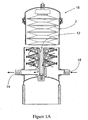
- FIG 1 shows a lenticular device that is suitable for the present invention.
- the lenticular device 2 is comprised of a central support structure formed of a series of radial ribs 4 that extend outwardly from a central hub 6.
- the hub 6 is hollow and forms the outlet from the device 2 when mounted to a central collection rod (as shown in Figure 1A).
- the outer surface of the ribs 4 is covered by one or more layer of a material formed from a cellulosic, cotton or wool and/or synthetic fibrous material 8 that incorporates one or more plugging constituent removing media.
- the outer edges of the material 8 and ribs 4 are sealed in a liquid tight arrangement by and outer edge seal 10.
- the device is at least a two-layer structure with either two layers of cellulose and/or synthetic fibrous material or at least one layer of cellulosic and/or synthetic fibrous material on top of a microporous membrane mounted on each side of the ribs 4.
- the plugging constituent removing media is contained throughout the structure, typically by the fibrous material and/or a binder. Additionally, or used as the binder (if used), a resin or material that imparts a desired charge to the structure to enhance adsorption such as a melamine formaldehyde or a epichlorohydrin cationic binder, especially a polyamido polyamine epichlorohydrin cationic resin as is well known in the art may also be used.
- a resin or material that imparts a desired charge to the structure to enhance adsorption such as a melamine formaldehyde or a epichlorohydrin cationic binder, especially a polyamido polyamine epichlorohydrin cationic resin as is well known in the art may also be used.
- the amount of media incorporated into the device is similar to that of the existing devices in the art and typically ranges from about 20% to about 80% ,preferably from about 50% to about 75% by weight.
- Such devices, their manufacture and use are well known in the art, see US Patents 4,305,782 ; 4,309,247 ; 4,645,567 ; 4,859,340 ; 4,981,591 and 5,085,780 .
- Figure 1A shows a series of such lenticular devices mounted to a central pipe 12 which is in fluid communication with the outlet 14 of the housing 16. Also shown is an inlet 18 that allows fluid to enter the housing 16, flow through the devices 2 to the central pipe 12 and then to outlet 14.
- FIG. 2 shows a filtration cartridge design 20 that contains one or more sheets of membrane 24 in which the one or more plugging constituent media has been incorporated as a filler material.
- the membrane based device as shown is in the form of a cartridge as is well known in the art. Other membrane devices use stacked disks of material such as MILLIDISK devices available from Millipore Corporation and any of membrane containing device formats used in normal flow configurations may be used in the present invention.
- the cartridge 20 has two end caps, a top cap 21 that is solid and has no opening in it and a bottom cap 22 which contains an opening 25 that can act either as an outlet (preferred) or as an inlet (less preferred).
- a hollow porous central core 23 is between the two end caps 21, 22 and the membrane is placed outside of this core.
- the interior of the core forms a space 27.
- the membrane(s) 24, core 23 and end caps 21, 22 are liquid tightly sealed to each other such that fluid from the exterior of the device must flow through the membrane(s) 24 and core to reach the space 27 and eventually the opening 25 (in this embodiment an outlet).
- filler material into membranes is well known in the art, see US Patents 5,531,899 and 5,093,197 .
- These membranes are formed by selecting a matrix material such as a plastic including but not limited to celluloses, regenerated celluloses, polyethylenes, polypropylenes, EVA copolymers, PVDF, polysulfones, polyethersulfones, polyarylsulfones, polyphenylsulfones, polyamides, polyimides, nylons and the like; a porogen, such as mineral oil, salt, sugar starch or a non solvent for the matrix material, such as PvP or even water and one or more fillers selected from the plugging constituent removing media.
- a matrix material such as a plastic including but not limited to celluloses, regenerated celluloses, polyethylenes, polypropylenes, EVA copolymers, PVDF, polysulfones, polyethersulfones, polyarylsulfones, polypheny
- the matrix is melted, filler and porogen (such as mineral oil) is added and the entire molten mass is extruded, calendared or rolled into a flat sheet. The porogen is then extracted to forma filled porous membrane. In some cases, the sheet is then stretched in on or cross directions to create even greater number and sizes or pores.
- the matrix is dissolved in a solvent with a porogen that is a non-solvent or weak solvent for the matrix. Filler is added as in the first process and the solution is stirred to form a homogeneous solution. It is then cast as a sheet and the solvent is driven off or exchanged in a nonsolvent solution such as water. The porogen is also removed either simultaneously or sequentially and a porous membrane sheet material is thereby formed.
- the membranes are at least microporous (0.05 micron average pore size to about 10 microns) or larger to allow good flow and flux characteristics.
- the membranes may be formed as non-woven materials such as spun bonded fibrous sheets that have the filler incorporated either into the spinning solution or bonded to the spun fibers before they are set (such as by simply dusting the spun fibers with a powder of the media where it is simply incorporated into the surface structure of the fibers).
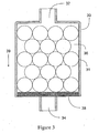
- Figure 3 shows a third embodiment in which the one or more plugging constituent removing media 31 has been packed into a housing 30 having an inlet 32, an outlet 34, and an inner volume 36.
- the media can retained in the housing by various well known means.
- a filter or screen 38 having pore sizes smaller than the particles of the filtration media 31 keeps the media 31 from escaping the housing 30and entering the fluid stream.
- the flow of fluid is shown by arrow 39.
- the media as shown is all of one size.
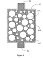
- various sized media may be used to create a more concentrated bed of media. This may be done by simply mixing various sized media particles 31A, 31B, 31C together as shown In Figure 3A or by arranging the various sized particles 31A, 31B and 31C in sequentially arranged beds of the same size as shown In Figure 3B.
- Figure 4 shows an alternative embodiment of Figure 3 in which the media is captured In a macroporous structure as a monolith 40.
- the first stage 110 of the one preferred embodiment of the process of this invention as shown in Figure 5 one utilizes a constant pressure mode of filtration.
- a protein or peptide containing solution 112 is retained by pressurized reservoir 114 and is pumped to the filtration media unit 116 by the pressure in the tank through conduit 118.
- the solution is subjected to a normal flow mode of filtration with the plugging constituents being retained by the media and the plugging constituent-free solution discharged as the filtrate from the first step 110.
- the filtrate is passed directly through conduit 120 for further downstream processing including the second step of filtration 122 (explained in detail below) and then to an outlet conduit 124.
- plugging constituents are retained by media unit 116 while the protein or peptide is passed through media 116.
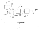
- FIG. 6 A second embodiment of the present invention is shown in Figure 6 in which a constant flow mode of operation is used.
- a pump 126 located between the reservoir 128 (typically a non-pressurized as compared to the pressurized vessel of the embodiment of Figure 5) and the first filtration step 130 to maintain the constant flow.
- the solution 131 is pumped through conduit 132 to the pump inlet 134 and then pumped through conduit 136 to the first filtration step130.
- the filter of the first step 130 may any of those mentioned above in the discussion of Figure 5.
- the solution is subjected to a normal flow mode of filtration with the plugging constituents being retained by the filter of the first step 130 and the plugging constituent free solution discharged as the filtrate from the first step 130.
- the filtrate is passed directly through conduit 138 for further downstream processing including the second step of filtration 140 (explained in detail below) and then to an outlet conduit 142.
- a recirculation loop (not shown) at the outlet (not shown) of the first filtration step and recirculate the filtrate through the filtration step one or more additional times to further reduce the plugging constituent level in the filtrate.
- Use of a valve (not shown) is the simplest means for controlling the flow between the recirculation loop and the downstream conduit. It has been found that one recirculation pass is sufficient Additional recirculation passes are generally unnecessary and increase manufacturing time and costs unnecessarily.
- the second filtration step (122or 140) one conducts a viral removal filtration after the removal of the plugging constituents.
- Viruses are removed from the plugging constituent-free solution by either a normal flow filter (NFF) or a tangential flow filtration (TFF) filter such as is described In USSN 09/706,003, filed November 3, 2000 .
- NPF normal flow filter
- TFF tangential flow filtration
- Representative suitable devices for the first step include those formed from fibrous media formed of cellulosic fibers, synthetic fibers or blends thereof, such as MILLISTAK®+ pads available from Millipore Corporation of Billerica, Massachusetts.
- Filtration can be effected with one or a plurality of devices wherein the feed protein or peptide containing solution is contacted with the devices in parallel or series flow.
- the filtrate from the plugging constituent removal step is directed to a viral filtration step.
- the viral filtration step utilizes one of more viral filtration (typically ultrafiltration) membranes that can be conducted either In the TFF mode or the NFF mode. In either mode, the filtration is conducted under conditions to retain the virus, generally having a 20 to 100 nanometer (nm) diameter, on the membrane surface while permitting passage of the biomolecule through the membrane.
- the membrane is flushed with water or an aqueous buffer solution to remove any retained biomolecules. The use of the flushing step permits obtaining higher yields of proteins or peptides substantially free of virus.
- FFF cartridge
- VIRESOLVE® NFP viral filters or as cassettes (for TFF) cassettes, available from Millipore Corporation of Billerica, Massachusetts.
- the viral filters utilized In the process of this Invention are characterized by a log retention value (LRV; the negative logarithm of the Sieving coefficient) for virus particles and other, particles that Increase monotomically with the diameter of the particle; in the size range of interest for virus of 20 to 100 nm diameter.
- LRV log retention value
- the LRV Increases continuously with the size of the particle projected area (the square of the particle diameter).
- satisfactory LRV of at least about 3 are obtained.
- the molecular weight cutoff is reduced thereby reducing protein or peptide recovery. Therefore, the user will choose a membrane that gives satisfactory LRV and biomolecule recovery.
- the membranes utilized in the process of this invention are capable of producing an LRV for virus of 3 and can extend to as high as about 8 or greater where the virus particle size is between a 10 and 100 nm diameter.
- the virus removal membranes utilized In the process of this invention are characterized by a protein molecular weight cut off of between about 500 and 1000 kilo Daltons (kD). In all cases, the empirical relationship with particle projected area Is retained. Log reduction values for virus particles (single solutes in solution; In absence of protein) depends upon the virus particle size. With small sized virus such as hepatitis, an LRV of greater than about 3 can be obtained and with larger sized virus such as the AIDS virus, a LRV of greater than 6 can be obtain for example.
- An lgG plugging constituent containing feed solution (SeraCare 5% Human Gamma Globulin, available from SeraCare, Inc., Catt#HS-9000) was added to a phosphate buffer (10g/L Difco FA buffer, pH 7.2, from Fisher Scientific, Cat# DF 2314150) and EDTA (10mM ethylenediamine tetra acidic acid, disodium-calcium salt available from Sigma Aldrich, cat# ED2SC).
- the feed solution was then modified to represent a 10% plugging constituents load by filtering 90% of the feed through a membrane that removed the plugging constituents (PLCXK membrane as cellulose UF membrane with a nominal molecular cutoff of 1000kDaltons available from Millipore Corporation of Billerica, Massachusetts.)
- PLCXK membrane as cellulose UF membrane with a nominal molecular cutoff of 1000kDaltons available from Millipore Corporation of Billerica, Massachusetts.
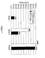
- Figure 7 shows the throughput results (liters of fluid processed /square meter of material before clogging of the material occurs) on the feed solution at 10% plugging constituents by three different modes of operation.
- Mode #1 used the conventional normal flow viral filter without any plugging constituent removal step using a VIRESOLVE® NFP viral filter of 13.5 cm 2 available from Millipore Corporation of Billerica, Massachusetts was provided for selectively removing plugging constituents from a protein solution in a normal flow (NFF) filtration process.
- VIRESOLVE® NFP viral filter of 13.5 cm 2 available from Millipore Corporation of Billerica, Massachusetts was provided for selectively removing plugging constituents from a protein solution in a normal flow (NFF) filtration process.
- Mode #2 used the first embodiment of the present invention using a MILLISTAK® device available from Millipore Corporation of Billerica, Massachusetts having 13.0 square centimeters of media.
- the filter is composed of charged fibrous cellulose and acid washed diatomaceous earth (Celpure® 60 diatomaceous earth available from Advanced Minerals Corporation of Lompoc, California) bound to the fibrous cellulose by a cationic binder. This was followed by a viral removal step using VIRESOLVE® NFP filter of 13.5 cm 2 available from Millipore Corporation of Billerica, Massachusetts.
- Mode #3 used another embodiment of the present invention using a MILLISTAK® device as described in Mode #2.
- the filtered fluid was then run through the media a second time, followed by a viral removal step using a VIRESOLVE® NFP filter of 13.5 cm 2 available from Millipore Corporation of Billerica, Massachusetts.
- FIG. 7 shows the Vmax (throughput) of the example.
- Mode #1 represents no plugging constituent removal step.
- Modes 2 and 3 represent different experiments run on different days with different batches of feed material.
- the Vmax was 200% greater than that of the Vmax obtained without the NFF removal step.
- the present invention provides a simple means for the removal of plugging constituents from a protein stream before viral filtration. This reduces the fouling and clogging that would otherwise occur, increasing throughput and flux dramatically. Additionally, this is done without necessarily the need for tangential flow filtration (TFF) that is more costly to purchase and to run and which needs to be cleaned between uses.
- the present invention allows one to dispose of the plugging constituent filter allowing one to eliminate the cost of cleaning and storing the membrane between uses and the cost and time of validating one's procedures in doing so to regulatory agencies such as the FDA.
Abstract
Description
- This Invention relates to a process for selectively prefiltering a stream containing one or more protein or peptide biomolecules before the final viral filtration step.. More particularly, this invention relates to a process for prefiltering a protein or peptide containing stream to selectively remove aggregates and other constituents that would plug the viral filter causing a premature termination of the filter's expected life..
- Plasma derived protein solutions such as immunoglobulin protein (lgG1) and other proteins (natural or recombinant) such as monoclonal antibodies and peptides routinely contain several constituents that can block or plug a viral filter. These plugging constituents include but are not limited aggregates such as protein aggregates, typically trimers or higher protein polymers; denatured proteins; lipids; triglycerides; and the like. When utilizing conventional filtration processes, these plugging constituents are undesirable since the filter, especially the viral clearance filter, rapidly becomes plugged even at low aggregate concentrations of 0.01 - 0.1 %. Accordingly, it has been necessary to utilize expensive gel chromatography or size exclusion chromatography processes to effect selective prefiltration of the protein or peptide stream to remove these constituents before viral filtration occurs. Alternatively, one can use an ultrafiltration membrane operated In a constant diafiltration mode to effect the prefiltration step, See
US Patent 6,365,395 . - Additionally, as the viral removal step is near the end of the purification train for the product, any filtration or prefiltration must not add any extractable Into the protein or peptide stream. What is desired is to have a prefiltration step that provides the desired removal of plugging constituents while limiting the introduction of extractables Into the stream.
- Accordingly, it would be desirable to provide a process for prefiltering a protein or peptide solution to avoid premature plugging of the filtration device utilized in the process while minimizing the introduction of extractables into the stream.
- In general terms, the present invention provides a process for prefiltering a protein or peptide containing solution before viral filtration. More specifically, the essential and optional features of the invention are set out in the accompanying maxi- and sub-claims respectively.
- The first filtration step is effected using a dead end (normal) filtration (NFF) filter device.
- The second filtration step to selectively retain virus can be effected with one or more ultrafiltration membranes either by tangential flow filtration (TFF) or by dead end (normal) filtration (NFF) wherein an agglomerate and viral free stream is produced. The one or more ultrafiltration membranes retain virus particles while permitting passage of the protein or peptide there through. Subsequent to the viral filtration step, the viral membrane can be flushed with water or an aqueous buffer solution to recover any biomolecule that may have been retained by the membrane.
- Preferably, the first filtration device is formed of compositions that are substantially free of extractable materials either prior to or subsequent to filtration.
- The use of the prefiltration step to remove plugging constituents from a protein or peptide solution provides substantial advantages over the filtration processes of the prior art. Since the device of the first step (removing plugging constituents) is operated In the normal flow mode, it may be disposable and there is no cleaning process that would be subject to validation procedures and the like. In addition, the normal flow mode of operation is less expensive to purchase and operate, as little capital needs to be expended to set up such a system as compared to a TFF ultrafiltration type system. Further, since the membrane utilized in the second step of removing virus particles does not foul with plugging constituents its useful life is extended.
-
- Figure 1 shows a filtration device according to a first embodiment of the present invention in cross sectional view.
- Figure 1A shows the first embodiment of Figure 1 in use in a housing in cross sectional view.
- Figure 2 shows a filtration device according to a second embodiment of the present invention.
- Figure 3 shows a filtration device according to a third embodiment of the present invention in cross sectional view.
- Figures 3A and 3B show alternative arrangements of the embodiment of Figure 3 in cross sectional view.
- Figure 4 shows a filtration device according to a fourth embodiment of the present invention.
- Figure 5 is a flow diagram illustrating a first preferred embodiment of the process of this invention.
- Figure 6 is a flow diagram illustrating another preferred embodiment of the process of this invention.
- Figure 7 is a chart of the VMAX of three different processes, the first of the prior art and two of the embodiments of the present invention.
- In accordance with this invention, a protein or peptide containing solution is prefiltered with a retentive media to selectively retain plugging constituents while permitting passage of proteins or peptides therethrough before a viral removal filtration step. This filtration step is effected using a device containing one or more plugging constituent removing media such as diatomaceous earth and blends thereof with silicates including, but not limited to classes (porous and non-porous) and pertite and the like. When utilizing these materials, substantially complete plugging constituent removal is effected while permitting recovery of greaterthan about 85% of the protein or peptide, preferably greater than about 90% of the protein or peptide.
- The device is in the form of a fibrous pad, such as a lenticular fibrous pad of cellulose, plastics or mixes of the two that contains one or more plugging constituent removing media or it may use one or more layers of a filter sheet material that contains one or more plugging constituent removing media as a filler or it may be a contained bed of one or more plugging constituent removing ' media through which the stream flows before entering the viral clearance filtration stage.
- The plugging constituent removing media may be one or more of a media selected from diatomaceous earth and blends thereof with silicates, perlite, alumina, silicas and the like. A preferred media is an acid washed diatomaceous earth, known as Celpure® media available from Advanced Minerals Corporation of Lompac, California. This is a preferred material in that the acid washing step removes most of the extractable material from the media such as various metal ions that otherwise might end up In the process stream during use.
- The media should have a specific surface area of at least 0.5 square meter per gram (0.5 m2 /gm), preferably in excess of 1 m2/gm and should be of a size of less than about 50 microns in diameter, preferably from about 1 to about 50 microns. It should be used in an amount sufficient to provide suitable removal of the plugging constituents at a reasonable cost and should be used in amounts that are capable of being held by the selected device format selected, The amount of media incorporated into the device is similar to that of the existing devices in the art and typically ranges from about 10% to about 90%, preferably from about 25% to about 75% by weight.
- Figure 1 shows a lenticular device that is suitable for the present invention. The
lenticular device 2 is comprised of a central support structure formed of a series ofradial ribs 4 that extend outwardly from acentral hub 6. Thehub 6 is hollow and forms the outlet from thedevice 2 when mounted to a central collection rod (as shown in Figure 1A). The outer surface of theribs 4 is covered by one or more layer of a material formed from a cellulosic, cotton or wool and/or syntheticfibrous material 8 that incorporates one or more plugging constituent removing media. The outer edges of thematerial 8 andribs 4 are sealed in a liquid tight arrangement by andouter edge seal 10. Preferably, the device is at least a two-layer structure with either two layers of cellulose and/or synthetic fibrous material or at least one layer of cellulosic and/or synthetic fibrous material on top of a microporous membrane mounted on each side of theribs 4. - The plugging constituent removing media is contained throughout the structure, typically by the fibrous material and/or a binder. Additionally, or used as the binder (if used), a resin or material that imparts a desired charge to the structure to enhance adsorption such as a melamine formaldehyde or a epichlorohydrin cationic binder, especially a polyamido polyamine epichlorohydrin cationic resin as is well known in the art may also be used.
- The amount of media incorporated into the device is similar to that of the existing devices in the art and typically ranges from about 20% to about 80% ,preferably from about 50% to about 75% by weight. Such devices, their manufacture and use are well known in the art, see
US Patents 4,305,782 ;4,309,247 ;4,645,567 ;4,859,340 ;4,981,591 and5,085,780 . - Figure 1A shows a series of such lenticular devices mounted to a
central pipe 12 which is in fluid communication with theoutlet 14 of thehousing 16. Also shown is aninlet 18 that allows fluid to enter thehousing 16, flow through thedevices 2 to thecentral pipe 12 and then tooutlet 14. - Figure 2 shows a
filtration cartridge design 20 that contains one or more sheets ofmembrane 24 in which the one or more plugging constituent media has been incorporated as a filler material. The membrane based device as shown is in the form of a cartridge as is well known in the art. Other membrane devices use stacked disks of material such as MILLIDISK devices available from Millipore Corporation and any of membrane containing device formats used in normal flow configurations may be used in the present invention. Thecartridge 20 has two end caps, atop cap 21 that is solid and has no opening in it and abottom cap 22 which contains an opening 25 that can act either as an outlet (preferred) or as an inlet (less preferred). A hollow porouscentral core 23 is between the twoend caps space 27. The membrane(s) 24,core 23 andend caps space 27 and eventually the opening 25 (in this embodiment an outlet). - The incorporation of filler material into membranes is well known in the art, see
US Patents 5,531,899 and5,093,197 . These membranes are formed by selecting a matrix material such as a plastic including but not limited to celluloses, regenerated celluloses, polyethylenes, polypropylenes, EVA copolymers, PVDF, polysulfones, polyethersulfones, polyarylsulfones, polyphenylsulfones, polyamides, polyimides, nylons and the like; a porogen, such as mineral oil, salt, sugar starch or a non solvent for the matrix material, such as PvP or even water and one or more fillers selected from the plugging constituent removing media. - Two main methods of forming filled membranes are commonly used. In the first the matrix is melted, filler and porogen (such as mineral oil) is added and the entire molten mass is extruded, calendared or rolled into a flat sheet. The porogen is then extracted to forma filled porous membrane. In some cases, the sheet is then stretched in on or cross directions to create even greater number and sizes or pores. ln the second common method, the matrix is dissolved in a solvent with a porogen that is a non-solvent or weak solvent for the matrix. Filler is added as in the first process and the solution is stirred to form a homogeneous solution. It is then cast as a sheet and the solvent is driven off or exchanged in a nonsolvent solution such as water. The porogen is also removed either simultaneously or sequentially and a porous membrane sheet material is thereby formed. Typicallly, the membranes are at least microporous (0.05 micron average pore size to about 10 microns) or larger to allow good flow and flux characteristics.
- Alternatively, the membranes may be formed as non-woven materials such as spun bonded fibrous sheets that have the filler incorporated either into the spinning solution or bonded to the spun fibers before they are set (such as by simply dusting the spun fibers with a powder of the media where it is simply incorporated into the surface structure of the fibers).
- Figure 3 shows a third embodiment in which the one or more plugging
constituent removing media 31 has been packed into ahousing 30 having aninlet 32, anoutlet 34, and aninner volume 36. The media can retained in the housing by various well known means. As shown, a filter orscreen 38 having pore sizes smaller than the particles of thefiltration media 31 keeps themedia 31 from escaping the housing 30and entering the fluid stream. The flow of fluid is shown byarrow 39. The media as shown is all of one size. Alternatively, various sized media may be used to create a more concentrated bed of media. This may be done by simply mixing varioussized media particles sized particles - Figure 4 shows an alternative embodiment of Figure 3 in which the media is captured In a macroporous structure as a
monolith 40. - Other designs and configurations may also be used to form the device containing the media and It is meant to encompass them in the present invention. The key items is that the there should be sufficient amounts of media to remove a substantial portion of the plugging constituents at good flow and flux rates so as to provide for an efficient removal of the constituents.
- In the
first stage 110 of the one preferred embodiment of the process of this invention as shown in Figure 5 one utilizes a constant pressure mode of filtration. A protein orpeptide containing solution 112 is retained bypressurized reservoir 114 and is pumped to thefiltration media unit 116 by the pressure in the tank throughconduit 118. The solution is subjected to a normal flow mode of filtration with the plugging constituents being retained by the media and the plugging constituent-free solution discharged as the filtrate from thefirst step 110. The filtrate is passed directly throughconduit 120 for further downstream processing including the second step of filtration 122 (explained in detail below) and then to anoutlet conduit 124. By operating in this manner plugging constituents are retained bymedia unit 116 while the protein or peptide is passed throughmedia 116. - Alternatively, one could use a pump to create the constant pressure of the system although it is not preferred as the pump output would need to be carefully controlled to a constant pressure via valves or pump speed and would require a feedback system to ensure that the pressure is kept constant.
- A second embodiment of the present invention is shown in Figure 6 in which a constant flow mode of operation is used. In this system one uses a
pump 126 located between the reservoir 128 (typically a non-pressurized as compared to the pressurized vessel of the embodiment of Figure 5) and thefirst filtration step 130 to maintain the constant flow. Thesolution 131 is pumped throughconduit 132 to thepump inlet 134 and then pumped throughconduit 136 to the first filtration step130. Again the filter of thefirst step 130 may any of those mentioned above in the discussion of Figure 5. The solution is subjected to a normal flow mode of filtration with the plugging constituents being retained by the filter of thefirst step 130 and the plugging constituent free solution discharged as the filtrate from thefirst step 130. The filtrate is passed directly throughconduit 138 for further downstream processing including the second step of filtration 140 (explained in detail below) and then to anoutlet conduit 142. If one desires, one can add a recirculation loop (not shown) at the outlet (not shown) of the first filtration step and recirculate the filtrate through the filtration step one or more additional times to further reduce the plugging constituent level in the filtrate. Use of a valve (not shown) is the simplest means for controlling the flow between the recirculation loop and the downstream conduit. It has been found that one recirculation pass is sufficient Additional recirculation passes are generally unnecessary and increase manufacturing time and costs unnecessarily. - In the second filtration step (122or 140), one conducts a viral removal filtration after the removal of the plugging constituents. Viruses are removed from the plugging constituent-free solution by either a normal flow filter (NFF) or a tangential flow filtration (TFF) filter such as is described In
USSN 09/706,003, filed November 3, 2000 - Representative suitable devices for the first step Include those formed from fibrous media formed of cellulosic fibers, synthetic fibers or blends thereof, such as MILLISTAK®+ pads available from Millipore Corporation of Billerica, Massachusetts.
- Filtration can be effected with one or a plurality of devices wherein the feed protein or peptide containing solution is contacted with the devices in parallel or series flow.
- When removing virus from a protein or peptide containing solution substantially free of plugging constituents, the filtrate from the plugging constituent removal step is directed to a viral filtration step. The viral filtration step utilizes one of more viral filtration (typically ultrafiltration) membranes that can be conducted either In the TFF mode or the NFF mode. In either mode, the filtration is conducted under conditions to retain the virus, generally having a 20 to 100 nanometer (nm) diameter, on the membrane surface while permitting passage of the biomolecule through the membrane. In addition, when filtration of the feed stream is completed, the membrane is flushed with water or an aqueous buffer solution to remove any retained biomolecules. The use of the flushing step permits obtaining higher yields of proteins or peptides substantially free of virus.
- Representative suitable ultrafiltration membranes which can be utilized In the virus removal step Include those formed from regenerated cellulose, polyethersulfone, polyarylsulphones, polysulfone, polyimide, polyamide, polyvinylidenedifluoride (PVDF) or the like and are known as VIRESOLVE® membranes and RETROPORE™ membranes available from Millipore Corporation of Billerica, Massachusetts. These can be supplied in either a cartridge (NFF) form, such as VIRESOLVE® NFP viral filters, or as cassettes (for TFF), such as PELLICON® cassettes, available from Millipore Corporation of Billerica, Massachusetts.
- The viral filters utilized In the process of this Invention are characterized by a log retention value (LRV; the negative logarithm of the Sieving coefficient) for virus particles and other, particles that Increase monotomically with the diameter of the particle; in the size range of interest for virus of 20 to 100 nm diameter. Empirically, the LRV Increases continuously with the size of the particle projected area (the square of the particle diameter). Where one is concerned with removing small sized virus particles from a protein or peptide containing solution, satisfactory LRV of at least about 3 are obtained. However, the molecular weight cutoff is reduced thereby reducing protein or peptide recovery. Therefore, the user will choose a membrane that gives satisfactory LRV and biomolecule recovery. In any event, the membranes utilized in the process of this invention are capable of producing an LRV for virus of 3 and can extend to as high as about 8 or greater where the virus particle size is between a 10 and 100 nm diameter. In addition, the virus removal membranes utilized In the process of this invention are characterized by a protein molecular weight cut off of between about 500 and 1000 kilo Daltons (kD). In all cases, the empirical relationship with particle projected area Is retained. Log reduction values for virus particles (single solutes in solution; In absence of protein) depends upon the virus particle size. With small sized virus such as hepatitis, an LRV of greater than about 3 can be obtained and with larger sized virus such as the AIDS virus, a LRV of greater than 6 can be obtain for example.
- The following example illustrates the present invention and is not Intended to limit the same.
- An lgG plugging constituent containing feed solution (SeraCare 5% Human Gamma Globulin, available from SeraCare, Inc., Catt#HS-9000) was added to a phosphate buffer (10g/L Difco FA buffer, pH 7.2, from Fisher Scientific, Cat# DF 2314150) and EDTA (10mM ethylenediamine tetra acidic acid, disodium-calcium salt available from Sigma Aldrich, cat# ED2SC).
- The feed solution was then modified to represent a 10% plugging constituents load by filtering 90% of the feed through a membrane that removed the plugging constituents (PLCXK membrane as cellulose UF membrane with a nominal molecular cutoff of 1000kDaltons available from Millipore Corporation of Billerica, Massachusetts.)
- Figure 7 shows the throughput results (liters of fluid processed /square meter of material before clogging of the material occurs) on the feed solution at 10% plugging constituents by three different modes of operation.
-
Mode # 1 used the conventional normal flow viral filter without any plugging constituent removal step using a VIRESOLVE® NFP viral filter of 13.5 cm2 available from Millipore Corporation of Billerica, Massachusetts was provided for selectively removing plugging constituents from a protein solution in a normal flow (NFF) filtration process. -
Mode # 2 used the first embodiment of the present invention using a MILLISTAK® device available from Millipore Corporation of Billerica, Massachusetts having 13.0 square centimeters of media. The filter is composed of charged fibrous cellulose and acid washed diatomaceous earth (Celpure® 60 diatomaceous earth available from Advanced Minerals Corporation of Lompoc, California) bound to the fibrous cellulose by a cationic binder. This was followed by a viral removal step using VIRESOLVE® NFP filter of 13.5 cm2 available from Millipore Corporation of Billerica, Massachusetts. - Mode #3 used another embodiment of the present invention using a MILLISTAK® device as described in
Mode # 2. The filtered fluid was then run through the media a second time, followed by a viral removal step using a VIRESOLVE® NFP filter of 13.5 cm2 available from Millipore Corporation of Billerica, Massachusetts. - Figure 7 shows the Vmax (throughput) of the example.
Mode # 1 represents no plugging constituent removal step.Modes 2 and 3 represent different experiments run on different days with different batches of feed material. - Overall one can see the dramatic improvement in throughput and flux obtained with the NFF plugging constituent removal step. The Vmax was 200% greater than that of the Vmax obtained without the NFF removal step.
- The present invention provides a simple means for the removal of plugging constituents from a protein stream before viral filtration. This reduces the fouling and clogging that would otherwise occur, increasing throughput and flux dramatically. Additionally, this is done without necessarily the need for tangential flow filtration (TFF) that is more costly to purchase and to run and which needs to be cleaned between uses. The present invention allows one to dispose of the plugging constituent filter allowing one to eliminate the cost of cleaning and storing the membrane between uses and the cost and time of validating one's procedures in doing so to regulatory agencies such as the FDA.
Claims (5)
- A process for selectively removing plugging constituents and virus particles from an aqueous protein or peptide solution that comprises:first filtering a protein or peptide solution containing said plugging constituents and viruses through a device containing one or more plugging constituent removing media in a normal flow filtration mode of operation,recovering the plugging constituent-free protein or peptide solution, andsecondly directly filtering said protein or peptide solution through one or more ultrafiltration membranes having a molecular weight cut off of between about 200 kD and about 1000 kD to retain virus particles in said one or more ultrafiltration membranes at a level of at least 3 LRV, and to recover an aqueous, virus-free protein or peptide solution, characterized in that the first filter device is in the form of a fibrous pad and the plugging constituent removing medium comprises diatomaceous earth.
- The process of claim 1,a) further comprising the step of flushing retained biomolecules from said one or more ultrafiltration membranes, orb) wherein filtration with said one or more ultrafiltration membranes is effected by tangential flow filtration, orc) wherein filtration with said one or more ultrafiltration membranes is effected in a normal flow filtration mode of operation.
- The process of claim 1 wherein the fibrous pad comprisesa) one or more layers of adsorptive depth filters, orb) one or more layers of filled microporous membranes, orc) one or more beds containing said one or more plugging constituent removing media.
- The process of claim 1 whereina) the fibrous pad comprises one or more layers of filled microporous membranes wherein the membranes are formed of a material selected from the group consisting of regenerated cellulose, polyethersulfone, polyarlylsulphone, polysulfone, polyimide, polyamide or polyuvinylidenedifluoride, orb) the fibrous pad comprises one or more layers of adsorptive depth filters made of a material selected from the group consisting of cellulosic fibers, synthetic fibers and blends thereof, orc) the fibrous pad comprises one or more layers of adsorptive depth filters made of a material selected from the group consisting of cellulosic fibers, synthetic fibers and blends .. thereof and the diatomaceous earth is blended with one or more further plugging constituent removing media selected from the group consisting of silicates and perlite.
- The process of any preceding claim, wherein the plugging constituent removing medium comprises acid washed diatomaceous earth.
Applications Claiming Priority (1)
| Application Number | Priority Date | Filing Date | Title |
|---|---|---|---|
| PCT/US2003/015790 WO2004103530A1 (en) | 2003-05-19 | 2003-05-19 | Process for prefiltration of a protein solution |
Publications (2)
| Publication Number | Publication Date |
|---|---|
| EP1624950A1 EP1624950A1 (en) | 2006-02-15 |
| EP1624950B1 true EP1624950B1 (en) | 2007-07-11 |
Family
ID=33476223
Family Applications (1)
| Application Number | Title | Priority Date | Filing Date |
|---|---|---|---|
| EP03799802A Expired - Lifetime EP1624950B1 (en) | 2003-05-19 | 2003-05-19 | Process for prefiltration of a protein solution |
Country Status (6)
| Country | Link |
|---|---|
| EP (1) | EP1624950B1 (en) |
| AT (1) | ATE366617T1 (en) |
| AU (1) | AU2003299514A1 (en) |
| DE (1) | DE60314916T2 (en) |
| ES (1) | ES2290553T3 (en) |
| WO (1) | WO2004103530A1 (en) |
Cited By (3)
| Publication number | Priority date | Publication date | Assignee | Title |
|---|---|---|---|---|
| US8158405B2 (en) | 2008-06-30 | 2012-04-17 | General Electric Company | Process for concentrating and processing fluid samples |
| WO2012175156A1 (en) | 2011-06-24 | 2012-12-27 | Sartorius Stedim Biotech Gmbh | Method for separating biopolymer units and viruses from a fluid |
| US8546127B2 (en) | 2008-06-30 | 2013-10-01 | General Electric Company | Bacteria/RNA extraction device |
Families Citing this family (5)
| Publication number | Priority date | Publication date | Assignee | Title |
|---|---|---|---|---|
| US7390403B2 (en) * | 2004-03-19 | 2008-06-24 | Millipore Corporation | Prefilter system for biological systems |
| AU2008266131B2 (en) | 2007-06-15 | 2011-10-20 | Amgen Inc. | Methods of treating cell culture media for use in a bioreactor |
| SG10201609893SA (en) * | 2009-02-27 | 2017-01-27 | Emd Millipore Corp | Membrane with sulfonic groups for removing protein aggregates |
| IT1398646B1 (en) * | 2010-03-05 | 2013-03-08 | Macchi | SEPARATION DEVICE |
| CN105980047B (en) | 2013-12-12 | 2019-01-04 | Emd密理博公司 | Use the filter protein isolate containing acrylamide |
Family Cites Families (4)
| Publication number | Priority date | Publication date | Assignee | Title |
|---|---|---|---|---|
| US6096872A (en) * | 1997-10-14 | 2000-08-01 | Ortho Diagnostic Systems, Inc. | Viral clearance process |
| US6365395B1 (en) * | 2000-11-03 | 2002-04-02 | Millipore Corporation | Process for removing protein aggregates and virus from a protein solution |
| DE10114537A1 (en) * | 2001-03-21 | 2002-10-24 | Elipsa Gmbh | Separation of highly heterogeneous mixtures, e.g. proteins, comprises using array of filter membranes with systematically varying separation properties |
| US7118675B2 (en) * | 2002-02-04 | 2006-10-10 | Millipore Corporation | Process for removing protein aggregates and virus from a protein solution |
-
2003
- 2003-05-19 DE DE60314916T patent/DE60314916T2/en not_active Expired - Lifetime
- 2003-05-19 AT AT03799802T patent/ATE366617T1/en not_active IP Right Cessation
- 2003-05-19 AU AU2003299514A patent/AU2003299514A1/en not_active Abandoned
- 2003-05-19 WO PCT/US2003/015790 patent/WO2004103530A1/en active IP Right Grant
- 2003-05-19 EP EP03799802A patent/EP1624950B1/en not_active Expired - Lifetime
- 2003-05-19 ES ES03799802T patent/ES2290553T3/en not_active Expired - Lifetime
Non-Patent Citations (1)
| Title |
|---|
| None * |
Cited By (4)
| Publication number | Priority date | Publication date | Assignee | Title |
|---|---|---|---|---|
| US8158405B2 (en) | 2008-06-30 | 2012-04-17 | General Electric Company | Process for concentrating and processing fluid samples |
| US8546127B2 (en) | 2008-06-30 | 2013-10-01 | General Electric Company | Bacteria/RNA extraction device |
| WO2012175156A1 (en) | 2011-06-24 | 2012-12-27 | Sartorius Stedim Biotech Gmbh | Method for separating biopolymer units and viruses from a fluid |
| DE102011105525A1 (en) | 2011-06-24 | 2012-12-27 | Sartorius Stedim Biotech Gmbh | Process for separating biopolymer aggregates and viruses from a fluid |
Also Published As
| Publication number | Publication date |
|---|---|
| ES2290553T3 (en) | 2008-02-16 |
| DE60314916T2 (en) | 2008-04-10 |
| WO2004103530A1 (en) | 2004-12-02 |
| ATE366617T1 (en) | 2007-08-15 |
| AU2003299514A1 (en) | 2004-12-13 |
| DE60314916D1 (en) | 2007-08-23 |
| EP1624950A1 (en) | 2006-02-15 |
Similar Documents
| Publication | Publication Date | Title |
|---|---|---|
| US20030201229A1 (en) | Process for prefiltration of a protein solution | |
| EP1577319B1 (en) | Protein purification with prefiltering | |
| CA2132683C (en) | Microfiltration and/or ultrafiltration membrane method of the preparation of such a membrane, and a method of the filtration of a liquid by means of such a membrane | |
| US7465397B2 (en) | Process for removing protein aggregates and virus from a protein solution | |
| CA2892233A1 (en) | Filter device combining beads and fibers | |
| WO2013103906A1 (en) | Multi-staged filtration system for blood fluid removal | |
| JPH055532B2 (en) | ||
| JP2001520572A (en) | Filter cartridge for gravity feed water treatment equipment | |
| WO1999025726A1 (en) | Method and apparatus for isolation and purification of biomolecules | |
| EP1624950B1 (en) | Process for prefiltration of a protein solution | |
| JP2001521814A (en) | Membrane filtration device | |
| MXPA00008077A (en) | Filter for removing solids from liquids. | |
| US20150367267A1 (en) | Filtering methods for fluids and devices for carrying out said methods | |
| US7700762B2 (en) | Plasmid DNA clarification | |
| JPH09253632A (en) | Water treatment apparatus | |
| JPH03196891A (en) | Water purifier | |
| US20060254984A1 (en) | Hollow Fiber Membrane Adsorber and Process for the Use Thereof | |
| KR102508296B1 (en) | A water treatment device using a precision filtration film of a highly permeable hydrophilic cellulose | |
| JPH0824590A (en) | Method for filtering concentrated organic solution | |
| JP2011092801A (en) | Water purifying filter and water purifier having the same | |
| JPH01254222A (en) | Membrane separation method | |
| JP2011092800A (en) | Water purifying filter and water purifier having the same | |
| CN114980995A (en) | Two-stage filter for removing microorganisms from water | |
| JPH0679146A (en) | Filtration method | |
| JPH05329336A (en) | Filtering method |
Legal Events
| Date | Code | Title | Description |
|---|---|---|---|
| PUAI | Public reference made under article 153(3) epc to a published international application that has entered the european phase |
Free format text: ORIGINAL CODE: 0009012 |
|
| 17P | Request for examination filed |
Effective date: 20051119 |
|
| AK | Designated contracting states |
Kind code of ref document: A1 Designated state(s): AT BE BG CH CY CZ DE DK EE ES FI FR GB GR HU IE IT LI LU MC NL PT RO SE SI SK TR |
|
| DAX | Request for extension of the european patent (deleted) | ||
| GRAP | Despatch of communication of intention to grant a patent |
Free format text: ORIGINAL CODE: EPIDOSNIGR1 |
|
| GRAS | Grant fee paid |
Free format text: ORIGINAL CODE: EPIDOSNIGR3 |
|
| GRAA | (expected) grant |
Free format text: ORIGINAL CODE: 0009210 |
|
| AK | Designated contracting states |
Kind code of ref document: B1 Designated state(s): AT BE BG CH CY CZ DE DK EE ES FI FR GB GR HU IE IT LI LU MC NL PT RO SE SI SK TR |
|
| REG | Reference to a national code |
Ref country code: GB Ref legal event code: FG4D |
|
| REG | Reference to a national code |
Ref country code: CH Ref legal event code: EP |
|
| REF | Corresponds to: |
Ref document number: 60314916 Country of ref document: DE Date of ref document: 20070823 Kind code of ref document: P |
|
| REG | Reference to a national code |
Ref country code: IE Ref legal event code: FG4D |
|
| REG | Reference to a national code |
Ref country code: CH Ref legal event code: NV Representative=s name: PATENTANWAELTE SCHAAD, BALASS, MENZL & PARTNER AG |
|
| ET | Fr: translation filed | ||
| PG25 | Lapsed in a contracting state [announced via postgrant information from national office to epo] |
Ref country code: BG Free format text: LAPSE BECAUSE OF FAILURE TO SUBMIT A TRANSLATION OF THE DESCRIPTION OR TO PAY THE FEE WITHIN THE PRESCRIBED TIME-LIMIT Effective date: 20071011 Ref country code: PT Free format text: LAPSE BECAUSE OF FAILURE TO SUBMIT A TRANSLATION OF THE DESCRIPTION OR TO PAY THE FEE WITHIN THE PRESCRIBED TIME-LIMIT Effective date: 20071211 Ref country code: FI Free format text: LAPSE BECAUSE OF FAILURE TO SUBMIT A TRANSLATION OF THE DESCRIPTION OR TO PAY THE FEE WITHIN THE PRESCRIBED TIME-LIMIT Effective date: 20070711 |
|
| REG | Reference to a national code |
Ref country code: ES Ref legal event code: FG2A Ref document number: 2290553 Country of ref document: ES Kind code of ref document: T3 |
|
| PG25 | Lapsed in a contracting state [announced via postgrant information from national office to epo] |
Ref country code: AT Free format text: LAPSE BECAUSE OF FAILURE TO SUBMIT A TRANSLATION OF THE DESCRIPTION OR TO PAY THE FEE WITHIN THE PRESCRIBED TIME-LIMIT Effective date: 20070711 |
|
| PG25 | Lapsed in a contracting state [announced via postgrant information from national office to epo] |
Ref country code: GR Free format text: LAPSE BECAUSE OF FAILURE TO SUBMIT A TRANSLATION OF THE DESCRIPTION OR TO PAY THE FEE WITHIN THE PRESCRIBED TIME-LIMIT Effective date: 20071012 Ref country code: DK Free format text: LAPSE BECAUSE OF FAILURE TO SUBMIT A TRANSLATION OF THE DESCRIPTION OR TO PAY THE FEE WITHIN THE PRESCRIBED TIME-LIMIT Effective date: 20070711 |
|
| PLBE | No opposition filed within time limit |
Free format text: ORIGINAL CODE: 0009261 |
|
| STAA | Information on the status of an ep patent application or granted ep patent |
Free format text: STATUS: NO OPPOSITION FILED WITHIN TIME LIMIT |
|
| PG25 | Lapsed in a contracting state [announced via postgrant information from national office to epo] |
Ref country code: SK Free format text: LAPSE BECAUSE OF FAILURE TO SUBMIT A TRANSLATION OF THE DESCRIPTION OR TO PAY THE FEE WITHIN THE PRESCRIBED TIME-LIMIT Effective date: 20070711 Ref country code: CZ Free format text: LAPSE BECAUSE OF FAILURE TO SUBMIT A TRANSLATION OF THE DESCRIPTION OR TO PAY THE FEE WITHIN THE PRESCRIBED TIME-LIMIT Effective date: 20070711 |
|
| 26N | No opposition filed |
Effective date: 20080414 |
|
| PG25 | Lapsed in a contracting state [announced via postgrant information from national office to epo] |
Ref country code: RO Free format text: LAPSE BECAUSE OF FAILURE TO SUBMIT A TRANSLATION OF THE DESCRIPTION OR TO PAY THE FEE WITHIN THE PRESCRIBED TIME-LIMIT Effective date: 20070711 Ref country code: SE Free format text: LAPSE BECAUSE OF FAILURE TO SUBMIT A TRANSLATION OF THE DESCRIPTION OR TO PAY THE FEE WITHIN THE PRESCRIBED TIME-LIMIT Effective date: 20071011 |
|
| PG25 | Lapsed in a contracting state [announced via postgrant information from national office to epo] |
Ref country code: MC Free format text: LAPSE BECAUSE OF NON-PAYMENT OF DUE FEES Effective date: 20080531 |
|
| PG25 | Lapsed in a contracting state [announced via postgrant information from national office to epo] |
Ref country code: EE Free format text: LAPSE BECAUSE OF FAILURE TO SUBMIT A TRANSLATION OF THE DESCRIPTION OR TO PAY THE FEE WITHIN THE PRESCRIBED TIME-LIMIT Effective date: 20070711 Ref country code: IE Free format text: LAPSE BECAUSE OF NON-PAYMENT OF DUE FEES Effective date: 20080519 |
|
| PG25 | Lapsed in a contracting state [announced via postgrant information from national office to epo] |
Ref country code: SI Free format text: LAPSE BECAUSE OF FAILURE TO SUBMIT A TRANSLATION OF THE DESCRIPTION OR TO PAY THE FEE WITHIN THE PRESCRIBED TIME-LIMIT Effective date: 20070711 |
|
| PG25 | Lapsed in a contracting state [announced via postgrant information from national office to epo] |
Ref country code: CY Free format text: LAPSE BECAUSE OF FAILURE TO SUBMIT A TRANSLATION OF THE DESCRIPTION OR TO PAY THE FEE WITHIN THE PRESCRIBED TIME-LIMIT Effective date: 20070711 |
|
| PG25 | Lapsed in a contracting state [announced via postgrant information from national office to epo] |
Ref country code: LU Free format text: LAPSE BECAUSE OF NON-PAYMENT OF DUE FEES Effective date: 20080519 Ref country code: HU Free format text: LAPSE BECAUSE OF FAILURE TO SUBMIT A TRANSLATION OF THE DESCRIPTION OR TO PAY THE FEE WITHIN THE PRESCRIBED TIME-LIMIT Effective date: 20080112 |
|
| PG25 | Lapsed in a contracting state [announced via postgrant information from national office to epo] |
Ref country code: TR Free format text: LAPSE BECAUSE OF FAILURE TO SUBMIT A TRANSLATION OF THE DESCRIPTION OR TO PAY THE FEE WITHIN THE PRESCRIBED TIME-LIMIT Effective date: 20070711 |
|
| REG | Reference to a national code |
Ref country code: CH Ref legal event code: PFA Owner name: EMD MILLIPORE CORPORATION Free format text: MILLIPORE CORPORATION#JOHN DANA HUBBARD, 290 CONCORD ROAD#BILLERICA, MA 01821 (US) -TRANSFER TO- EMD MILLIPORE CORPORATION#290 CONCORD ROAD#BILLERICA, MA 01821 (US) |
|
| REG | Reference to a national code |
Ref country code: NL Ref legal event code: TD Effective date: 20120227 |
|
| REG | Reference to a national code |
Ref country code: ES Ref legal event code: PC2A Owner name: EMD MILLIPORE CORPORATION Effective date: 20120416 |
|
| REG | Reference to a national code |
Ref country code: FR Ref legal event code: CD Owner name: EMD MILLIPORE CORPORATION Effective date: 20120327 |
|
| REG | Reference to a national code |
Ref country code: DE Ref legal event code: R082 Ref document number: 60314916 Country of ref document: DE Representative=s name: LUDERSCHMIDT, SCHUELER & PARTNER GBR, DE |
|
| REG | Reference to a national code |
Ref country code: DE Ref legal event code: R082 Ref document number: 60314916 Country of ref document: DE Representative=s name: MAI DOERR BESIER PATENTANWAELTE, DE Effective date: 20120613 Ref country code: DE Ref legal event code: R082 Ref document number: 60314916 Country of ref document: DE Representative=s name: MAI DOERR BESIER PATENTANWAELTE, DE Effective date: 20120628 Ref country code: DE Ref legal event code: R081 Ref document number: 60314916 Country of ref document: DE Owner name: EMD MILLIPORE CORPORATION, US Free format text: FORMER OWNER: MILLIPORE CORP., BILLERICA, US Effective date: 20120613 Ref country code: DE Ref legal event code: R081 Ref document number: 60314916 Country of ref document: DE Owner name: EMD MILLIPORE CORPORATION, BILLERICA, US Free format text: FORMER OWNER: MILLIPORE CORP., BILLERICA, MASS., US Effective date: 20120613 Ref country code: DE Ref legal event code: R082 Ref document number: 60314916 Country of ref document: DE Representative=s name: MAI DOERR BESIER EUROPEAN PATENT ATTORNEYS - E, DE Effective date: 20120613 Ref country code: DE Ref legal event code: R082 Ref document number: 60314916 Country of ref document: DE Representative=s name: MAI DOERR BESIER EUROPEAN PATENT ATTORNEYS - E, DE Effective date: 20120628 |
|
| REG | Reference to a national code |
Ref country code: FR Ref legal event code: PLFP Year of fee payment: 14 |
|
| REG | Reference to a national code |
Ref country code: FR Ref legal event code: PLFP Year of fee payment: 15 |
|
| REG | Reference to a national code |
Ref country code: FR Ref legal event code: PLFP Year of fee payment: 16 |
|
| PGFP | Annual fee paid to national office [announced via postgrant information from national office to epo] |
Ref country code: CH Payment date: 20220314 Year of fee payment: 20 |
|
| PGFP | Annual fee paid to national office [announced via postgrant information from national office to epo] |
Ref country code: FR Payment date: 20220308 Year of fee payment: 20 |
|
| PGFP | Annual fee paid to national office [announced via postgrant information from national office to epo] |
Ref country code: NL Payment date: 20220420 Year of fee payment: 20 |
|
| PGFP | Annual fee paid to national office [announced via postgrant information from national office to epo] |
Ref country code: IT Payment date: 20220412 Year of fee payment: 20 Ref country code: GB Payment date: 20220401 Year of fee payment: 20 Ref country code: ES Payment date: 20220602 Year of fee payment: 20 Ref country code: DE Payment date: 20220322 Year of fee payment: 20 |
|
| PGFP | Annual fee paid to national office [announced via postgrant information from national office to epo] |
Ref country code: BE Payment date: 20220420 Year of fee payment: 20 |
|
| REG | Reference to a national code |
Ref country code: DE Ref legal event code: R071 Ref document number: 60314916 Country of ref document: DE |
|
| REG | Reference to a national code |
Ref country code: NL Ref legal event code: MK Effective date: 20230518 |
|
| REG | Reference to a national code |
Ref country code: ES Ref legal event code: FD2A Effective date: 20230526 |
|
| REG | Reference to a national code |
Ref country code: CH Ref legal event code: PL |
|
| REG | Reference to a national code |
Ref country code: BE Ref legal event code: MK Effective date: 20230519 |
|
| REG | Reference to a national code |
Ref country code: GB Ref legal event code: PE20 Expiry date: 20230518 |
|
| P01 | Opt-out of the competence of the unified patent court (upc) registered |
Effective date: 20230602 |
|
| PG25 | Lapsed in a contracting state [announced via postgrant information from national office to epo] |
Ref country code: ES Free format text: LAPSE BECAUSE OF EXPIRATION OF PROTECTION Effective date: 20230520 |
|
| PG25 | Lapsed in a contracting state [announced via postgrant information from national office to epo] |
Ref country code: GB Free format text: LAPSE BECAUSE OF EXPIRATION OF PROTECTION Effective date: 20230518 |