EP1595505A2 - Apparatus for delivering a closure device - Google Patents
Apparatus for delivering a closure device Download PDFInfo
- Publication number
- EP1595505A2 EP1595505A2 EP05106654A EP05106654A EP1595505A2 EP 1595505 A2 EP1595505 A2 EP 1595505A2 EP 05106654 A EP05106654 A EP 05106654A EP 05106654 A EP05106654 A EP 05106654A EP 1595505 A2 EP1595505 A2 EP 1595505A2
- Authority
- EP
- European Patent Office
- Prior art keywords
- actuator
- distal
- carrier
- members
- sheath
- Prior art date
- Legal status (The legal status is an assumption and is not a legal conclusion. Google has not performed a legal analysis and makes no representation as to the accuracy of the status listed.)
- Granted
Links
- 230000008878 coupling Effects 0.000 claims description 15
- 238000010168 coupling process Methods 0.000 claims description 15
- 238000005859 coupling reaction Methods 0.000 claims description 15
- 239000003550 marker Substances 0.000 claims description 2
- 238000000034 method Methods 0.000 description 19
- 210000002105 tongue Anatomy 0.000 description 14
- 210000004204 blood vessel Anatomy 0.000 description 12
- 239000000463 material Substances 0.000 description 6
- 230000002792 vascular Effects 0.000 description 5
- 230000000881 depressing effect Effects 0.000 description 4
- 238000007789 sealing Methods 0.000 description 4
- 230000003213 activating effect Effects 0.000 description 3
- 230000000994 depressogenic effect Effects 0.000 description 3
- 238000002405 diagnostic procedure Methods 0.000 description 3
- 230000023597 hemostasis Effects 0.000 description 3
- 230000013011 mating Effects 0.000 description 3
- 238000002560 therapeutic procedure Methods 0.000 description 3
- 206010052428 Wound Diseases 0.000 description 2
- 208000027418 Wounds and injury Diseases 0.000 description 2
- 239000000853 adhesive Substances 0.000 description 2
- 230000001070 adhesive effect Effects 0.000 description 2
- 238000002399 angioplasty Methods 0.000 description 2
- 238000013459 approach Methods 0.000 description 2
- 239000008280 blood Substances 0.000 description 2
- 210000004369 blood Anatomy 0.000 description 2
- 239000012530 fluid Substances 0.000 description 2
- 238000003780 insertion Methods 0.000 description 2
- 230000037431 insertion Effects 0.000 description 2
- 238000012986 modification Methods 0.000 description 2
- 230000004048 modification Effects 0.000 description 2
- 229920000139 polyethylene terephthalate Polymers 0.000 description 2
- 239000005020 polyethylene terephthalate Substances 0.000 description 2
- -1 polytetrafluoroethylene Polymers 0.000 description 2
- 229920001343 polytetrafluoroethylene Polymers 0.000 description 2
- 239000004810 polytetrafluoroethylene Substances 0.000 description 2
- 125000006850 spacer group Chemical group 0.000 description 2
- 206010053567 Coagulopathies Diseases 0.000 description 1
- 102000008186 Collagen Human genes 0.000 description 1
- 108010035532 Collagen Proteins 0.000 description 1
- 208000005189 Embolism Diseases 0.000 description 1
- 206010018852 Haematoma Diseases 0.000 description 1
- 208000032843 Hemorrhage Diseases 0.000 description 1
- 239000004952 Polyamide Substances 0.000 description 1
- 230000000712 assembly Effects 0.000 description 1
- 238000000429 assembly Methods 0.000 description 1
- 230000000740 bleeding effect Effects 0.000 description 1
- 230000036772 blood pressure Effects 0.000 description 1
- 210000001715 carotid artery Anatomy 0.000 description 1
- 230000035602 clotting Effects 0.000 description 1
- 229920001436 collagen Polymers 0.000 description 1
- 230000000295 complement effect Effects 0.000 description 1
- 229920001577 copolymer Polymers 0.000 description 1
- 230000002708 enhancing effect Effects 0.000 description 1
- 210000003195 fascia Anatomy 0.000 description 1
- 210000001105 femoral artery Anatomy 0.000 description 1
- 238000002594 fluoroscopy Methods 0.000 description 1
- 238000003384 imaging method Methods 0.000 description 1
- 238000002513 implantation Methods 0.000 description 1
- 208000014674 injury Diseases 0.000 description 1
- 238000013152 interventional procedure Methods 0.000 description 1
- 229920000126 latex Polymers 0.000 description 1
- 239000004816 latex Substances 0.000 description 1
- 238000004519 manufacturing process Methods 0.000 description 1
- 239000000203 mixture Substances 0.000 description 1
- 238000012544 monitoring process Methods 0.000 description 1
- 230000002093 peripheral effect Effects 0.000 description 1
- 229920002647 polyamide Polymers 0.000 description 1
- 229920000728 polyester Polymers 0.000 description 1
- 229920001296 polysiloxane Polymers 0.000 description 1
- 229920002635 polyurethane Polymers 0.000 description 1
- 239000004814 polyurethane Substances 0.000 description 1
- 230000002028 premature Effects 0.000 description 1
- 230000001225 therapeutic effect Effects 0.000 description 1
- 230000000930 thermomechanical effect Effects 0.000 description 1
- 230000008733 trauma Effects 0.000 description 1
- 210000005166 vasculature Anatomy 0.000 description 1
- 230000000007 visual effect Effects 0.000 description 1
Images


Classifications
-
- A—HUMAN NECESSITIES
- A61—MEDICAL OR VETERINARY SCIENCE; HYGIENE
- A61B—DIAGNOSIS; SURGERY; IDENTIFICATION
- A61B17/00—Surgical instruments, devices or methods, e.g. tourniquets
- A61B17/08—Wound clamps or clips, i.e. not or only partly penetrating the tissue ; Devices for bringing together the edges of a wound
- A61B17/083—Clips, e.g. resilient
-
- A—HUMAN NECESSITIES
- A61—MEDICAL OR VETERINARY SCIENCE; HYGIENE
- A61B—DIAGNOSIS; SURGERY; IDENTIFICATION
- A61B17/00—Surgical instruments, devices or methods, e.g. tourniquets
- A61B17/0057—Implements for plugging an opening in the wall of a hollow or tubular organ, e.g. for sealing a vessel puncture or closing a cardiac septal defect
-
- A—HUMAN NECESSITIES
- A61—MEDICAL OR VETERINARY SCIENCE; HYGIENE
- A61B—DIAGNOSIS; SURGERY; IDENTIFICATION
- A61B17/00—Surgical instruments, devices or methods, e.g. tourniquets
- A61B17/064—Surgical staples, i.e. penetrating the tissue
-
- A—HUMAN NECESSITIES
- A61—MEDICAL OR VETERINARY SCIENCE; HYGIENE
- A61B—DIAGNOSIS; SURGERY; IDENTIFICATION
- A61B17/00—Surgical instruments, devices or methods, e.g. tourniquets
- A61B17/12—Surgical instruments, devices or methods, e.g. tourniquets for ligaturing or otherwise compressing tubular parts of the body, e.g. blood vessels, umbilical cord
- A61B17/128—Surgical instruments, devices or methods, e.g. tourniquets for ligaturing or otherwise compressing tubular parts of the body, e.g. blood vessels, umbilical cord for applying or removing clamps or clips
-
- A—HUMAN NECESSITIES
- A61—MEDICAL OR VETERINARY SCIENCE; HYGIENE
- A61B—DIAGNOSIS; SURGERY; IDENTIFICATION
- A61B17/00—Surgical instruments, devices or methods, e.g. tourniquets
- A61B2017/00004—(bio)absorbable, (bio)resorbable, resorptive
-
- A—HUMAN NECESSITIES
- A61—MEDICAL OR VETERINARY SCIENCE; HYGIENE
- A61B—DIAGNOSIS; SURGERY; IDENTIFICATION
- A61B17/00—Surgical instruments, devices or methods, e.g. tourniquets
- A61B17/0057—Implements for plugging an opening in the wall of a hollow or tubular organ, e.g. for sealing a vessel puncture or closing a cardiac septal defect
- A61B2017/00637—Implements for plugging an opening in the wall of a hollow or tubular organ, e.g. for sealing a vessel puncture or closing a cardiac septal defect for sealing trocar wounds through abdominal wall
-
- A—HUMAN NECESSITIES
- A61—MEDICAL OR VETERINARY SCIENCE; HYGIENE
- A61B—DIAGNOSIS; SURGERY; IDENTIFICATION
- A61B17/00—Surgical instruments, devices or methods, e.g. tourniquets
- A61B17/0057—Implements for plugging an opening in the wall of a hollow or tubular organ, e.g. for sealing a vessel puncture or closing a cardiac septal defect
- A61B2017/00646—Type of implements
- A61B2017/00668—Type of implements the implement being a tack or a staple
-
- A—HUMAN NECESSITIES
- A61—MEDICAL OR VETERINARY SCIENCE; HYGIENE
- A61B—DIAGNOSIS; SURGERY; IDENTIFICATION
- A61B17/00—Surgical instruments, devices or methods, e.g. tourniquets
- A61B17/0057—Implements for plugging an opening in the wall of a hollow or tubular organ, e.g. for sealing a vessel puncture or closing a cardiac septal defect
- A61B2017/00672—Locating means therefor, e.g. bleed back lumen
-
- A—HUMAN NECESSITIES
- A61—MEDICAL OR VETERINARY SCIENCE; HYGIENE
- A61B—DIAGNOSIS; SURGERY; IDENTIFICATION
- A61B17/00—Surgical instruments, devices or methods, e.g. tourniquets
- A61B2017/00831—Material properties
- A61B2017/00862—Material properties elastic or resilient
-
- A—HUMAN NECESSITIES
- A61—MEDICAL OR VETERINARY SCIENCE; HYGIENE
- A61B—DIAGNOSIS; SURGERY; IDENTIFICATION
- A61B17/00—Surgical instruments, devices or methods, e.g. tourniquets
- A61B17/064—Surgical staples, i.e. penetrating the tissue
- A61B2017/0641—Surgical staples, i.e. penetrating the tissue having at least three legs as part of one single body
-
- A—HUMAN NECESSITIES
- A61—MEDICAL OR VETERINARY SCIENCE; HYGIENE
- A61B—DIAGNOSIS; SURGERY; IDENTIFICATION
- A61B90/00—Instruments, implements or accessories specially adapted for surgery or diagnosis and not covered by any of the groups A61B1/00 - A61B50/00, e.g. for luxation treatment or for protecting wound edges
- A61B90/39—Markers, e.g. radio-opaque or breast lesions markers
Definitions
- the present invention relates generally to apparatus and methods for closing and/or sealing openings through tissue, and more particularly to apparatus and methods for delivering a closure element for closing a puncture in a blood vessel or other body lumen formed during a diagnostic or therapeutic procedure.
- Catheterization and interventional procedures such as angioplasty or stenting, generally are performed by inserting a hollow needle through a patient's skin and tissue into the vascular system.
- a guide wire may then be passed through the needle lumen into the patient's blood vessel accessed by the needle.
- the needle may be removed, and an introducer sheath may be advanced over the guide wire into the vessel, e.g., in conjunction with or subsequent to a dilator.
- a catheter or other device may then be advanced through a lumen of the introducer sheath and over the guide wire into a position for performing a medical procedure.
- the introducer sheath may facilitate introducing various devices into the vessel, while minimizing trauma to the vessel wall and/or minimizing blood loss during a procedure.
- the devices and introducer sheath may be removed, leaving a puncture site in the vessel wall. External pressure may be applied to the puncture site until clotting and wound sealing occur.
- This procedure may be time consuming and expensive, requiring as much as an hour of a physician's or nurse's time. It is also uncomfortable for the patient, and requires that the patient remain immobilized in the operating room, catheter lab, or holding area. In addition, a risk of hematoma exists from bleeding before hemostasis occurs.
- U.S. Patent No. 4,317,445 issued to Robinson, discloses a flashback chamber on a first end of a cannula that communicates with a port on a second end. The second end is percutaneously introduced into a patient until the port enters the vessel, whereupon blood, under normal blood pressure, may advance along the cannula and enter the flashback chamber, thereby providing a visual indication that the vessel has been entered.
- This reference does not discuss vascular wound closure, but is merely directed to an introducer device.
- U.S. Patent No. 5,674,231 issued to Green et al., discloses a deployable loop that may be advanced through a sheath into a vessel.
- the loop is intended to resiliently expand to engage the inner wall of the vessel, thereby facilitating holding the sheath in a desired location with respect to the vessel.
- the loop may also provide a support for facilitating deploying and deflecting a surgical clip against the vessel wall. Such a device, however, may risk engagement between the loop and the surgical clip, thereby preventing the loop from being withdrawn from the vessel.
- apparatus and methods for delivering a device for closing a vascular puncture site or other opening through tissue would be useful.
- the present invention is directed to apparatus and methods for closing and/or sealing openings through tissue, e.g., into body lumens, and more particularly to apparatus and methods for delivering a vascular closure element for closing a puncture in a blood vessel formed during a diagnostic or therapeutic procedure, e.g., when an introducer sheath is advanced into the vessel.
- an apparatus for delivering a closure element or other annular-shaped device into an opening through tissue, e.g., for engaging tissue adjacent to the opening to close and/or seal the opening.
- the apparatus includes an elongate member including proximal and distal ends, such as an introducer sheath that includes a lumen for advancing one or more devices into a body lumen during a procedure.
- a carrier assembly is slidable on the elongate member, the carrier assembly including an inner carrier member, a middle pusher member, and, optionally, an outer skin, nested together.
- Each member may have an annular shape, and may include a connector on its proximal end.
- the pusher member may be disposed about the carrier member to define a space distal to the pusher member along an outer surface of the carrier member.
- the outer skin has a length, whereby the outer skin may extend over the space and/or contact an outer surface of the elongate member. In a preferred embodiment, the outer skin extends a short distance beyond a distal end of the carrier member, such that the outer skin is slidable along the elongate member.
- An annular-shaped element e.g., a clip or other closure device, may be received on the carrier member within the space, the annular-shaped element being deployable from the space upon distal movement of the pusher member relative to the carrier member.
- the apparatus may include an actuator assembly including a housing and inner, intermediate, and outer actuator members that telescope relative to the housing and/or to each other.
- the housing may be connectable to the proximal end of the elongate member, e.g., to a hub on the proximal end by cooperating connectors on the hub and the housing.
- Each actuator member may include a connector on its distal end for engaging a respective member of the carrier assembly, thereby coupling movement of the carrier, pusher, and sheath members to the inner, intermediate, and outer actuator members, respectively. If the outer skin is eliminated from the carrier assembly, the outer actuator member may be eliminated from the actuator assembly.
- the actuator assembly includes a control member that is coupled to one or more of the actuator members, preferably, but not necessarily, the intermediate actuator member.
- the inner, intermediate, and outer actuator members may include cooperating detents for coupling distal movement of the inner, intermediate, and outer actuator members together in a predetermined manner as the control member is directed distally.
- a first set of cooperating detents may be provided that initially couples the inner, intermediate, and outer actuator members together, and releases the outer actuator member upon attaining a first distal position.
- the inner and intermediate actuator members may be directed distally further, consequently permitting the carrier and/or pusher members to be directed distally relative to the outer skin.
- the first set of cooperating detents may include a first detent on the outer tubular member and first pockets in the inner and intermediate tubular members for receiving the first detent therein.
- Cooperating ramps may be provided on the outer tubular member that are configured for disengaging the first detent from the first pockets upon attaining the first distal position, thereby allowing the inner and intermediate tubular members to be directed distally beyond the first distal position.
- the cooperating detents may include a second set of cooperating detents on the inner and intermediate actuator members for coupling movement of the inner and intermediate actuator members together to a second distal position distal to the first distal position.
- the intermediate actuator member may include a second detent
- the inner actuator member may include a second pocket for receiving the second detent therein.
- the housing or the outer actuator member may include a spring element for disengaging the second detent from the second pocket upon attaining the second distal position.
- the spring element may include a beam extending from the outer tubular member through slots in the inner and intermediate tubular members, the beam being received in the second pocket upon attaining the second distal position, thereby disengaging the second detent and allowing further distal movement of the intermediate member while substantially simultaneously coupling the inner and outer tubular members together.
- the intermediate actuator member may be advanced distally beyond the second distal position by directing the control member further distally, thereby directing the pusher member distally with respect to the carrier member to deploy the annular-shaped element from the space.
- the actuator assembly may also include an obturator or locator member that may be part of the actuator assembly or may be connected to the actuator assembly.
- a distal portion of the locator member may extend distally beyond the actuator members.
- the locator member has sufficient length such that the distal portion may extend beyond the distal end of the elongate member when the actuator assembly is connected to the elongate member.
- One or more positioning elements on the distal portion of the locator member may be movable from a collapsed configuration towards a transversely expanded configuration.
- a locking mechanism on the locator member and/or actuator assembly may releasably retain the positioning elements in the expanded configuration.
- the locator member is substantially permanently attached to the actuator assembly such that the distal portion extends through and beyond the inner actuator member.
- the actuator assembly may include a tubular portion or recess communicating via an interior of the inner actuator member with a lumen of the elongate member.
- the locator member may be inserted into the tubular portion until the positioning elements are disposed beyond the distal end of the elongate member.
- One of the inner, intermediate, and outer actuator members may include a third detent for engaging a release mechanism for disengaging the locking mechanism on the locator member.
- the positioning elements may be collapsed to the collapsed configuration upon advancing one of the inner, intermediate, and/or outer actuator members, preferably the intermediate actuator member, to its final distal position.
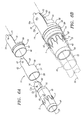
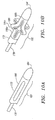
- FIGS. 1-4 show a first preferred embodiment of an apparatus 10 for delivering a closure element, such as a clip 5 (shown in phantom), into an opening through tissue for closing the opening (not shown).
- the apparatus 10 includes an introducer sheath 12, a housing or carrier assembly 14 slidably disposed on the sheath 12, and an actuator or actuator assembly 16 that is connectable to the introducer sheath 12.
- the apparatus 10 may also include a locator member or obturator 18, which may be part of the actuator assembly 16, as shown in FIGS. 1-3.
- the apparatus 310 may include an obturator 318 that is a separate subassembly that may be inserted through an actuator assembly 316 and/or sheath 312, as shown in FIGS. 11A and 11B.
- the introducer sheath 12 is generally a substantially flexible or semi-rigid tubular member including a lumen 20 extending along a longitudinal axis 28 between its proximal and distal ends 22, 24.
- the distal end 24 has a size and shape to facilitate insertion into an opening through tissue (not shown), e.g., having a tapered tip 26 for facilitating substantially atraumatic introduction through a passage and/or at least partially into a blood vessel or other body lumen accessed via the passage.
- the lumen 20 has a size for accommodating insertion of one or more devices therethrough, such as a catheter, guidewire, and the like (not shown).
- a hub assembly 30 is attached to the proximal end 22 of the sheath 12, e.g., by an adhesive, cooperating connectors, and/or a thermo-mechanical joint.
- the hub assembly 30 and the sheath 12 may define a passage 38 (see FIG. 1) therebetween that extends substantially parallel to the longitudinal axis 28.
- the hub assembly 30 may include a keel member 220 and one or more outer annular bodies 222-226 that may be attached to one another, e.g., using butt or lap joints secured with adhesives, mechanical connectors, and the like.
- the hub assembly 30 may include a rear main body 222, a spacer 223, a nose ring 224, and a strain relief forward nose 226 that may be substantially permanently attached to one another.
- the keel member 220 may include a tubular portion 246, and a shoulder portion 248 connected by a radial spoke 250 that may extend transversely with respect to the longitudinal axis 28.
- the proximal end 22 of the sheath 12 may be connected to the tubular portion 246 such that a passage 252 through the tubular portion 246 communicates with the lumen 20.
- the main body 222 and nose ring 224 may be connected to the shoulder portion 248 such that an annular passage 38 may be defined between the tubular portion 246 and the main body 222 and nose ring 224.
- the passage 38 may have a "C" shape along the portion of the hub assembly 30 through which the spoke 248 of the keel member 220 extends.
- the hub assembly 30 may also include one or more seals and/or valves that provide a fluid-tight seal.
- one or more devices such as the obturator 18 (not shown in FIG. 4), may be inserted into the lumen 20 of the sheath 12 without fluid passing proximally through the lumen 20.
- the hub assembly 30 may include a thrust washer and/or valve 228, a valve 230, a guide 232 for directing devices into the lumen 20 of the sheath 12, and a seal 234.
- the various seals and/or guides may be secured to the hub assembly 30 by a spacer 236 and/or an end cap 238.
- the hub assembly 30 may include one or more connectors on its proximal end 32, such as tabs 34 (see FIG. 1) and/or recesses or pockets (not shown) for cooperating with mating connectors on the actuator assembly 16, as described further below.
- the hub assembly 30 may also include a side port 36 that extends from the shoulder portion 248 to the passage 252, thereby communicating with the lumen 20.
- the side port 36 may communicate with tubing 37 (see FIG. 3A), for example, to infuse fluids into the lumen 20 through the sheath 12.
- the side port 36 may provide a "bleed back" indicator, such as that disclosed in co-pending application Serial No. 09/680,837, filed October 6, 2000, which is assigned to the assignee of the present invention.
- the disclosure of this application and any references cited therein are expressly incorporated herein by reference.
- the carrier assembly 14 is slidably disposed on an exterior of the sheath 12 and is configured for releasably holding the clip 5.
- the carrier assembly 14 is preferably slidable from a proximal position, e.g,, near, adjacent to, or at least partially disposed within the passage 38, to one or more distal positions towards the distal end 24 of the sheath 12, as explained further below.
- the hub assembly 30 may include a carrier release pin 240 that may be inserted into a hole, slot, or other aperture 242 in the shoulder portion 248. An inner tip 244 of the pin 240 may be received in one or more corresponding holes 51, 61, 71 (best seen in FIG. 6A) in the carrier assembly 14.
- the pin 240 may provide a safety feature, e.g., preventing premature advancement of the carrier assembly 14 and/or deployment of the clip 5, and/or may assist in aligning the carrier assembly 14 as will be appreciated by those skilled in the art.
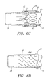
- the carrier assembly 14 may include an inner carrier member 40, a middle pusher member 42, and an outer anchor member 44 that may be nested together and coaxially disposed around the sheath 12 (shown in phantom in FIG. 6B).
- the carrier member 40 is an annular-shaped body 32 including proximal and distal ends 46, 48.
- an "annular-shaped body” or “annular body” (whether referring to the carrier assembly 14 or the clip 5) includes any hollow body, e.g., including one or more structures surrounding an opening, whether the body is substantially flat or has a significant thickness or depth.
- an annular-shaped body may be circular, it may include other noncircular shapes as well, such as elliptical or other shapes that are asymmetrical about a central axis.
- a tongue 50 may extend proximally from the proximal end 46 substantially parallel to the longitudinal axis 28.
- the tongue 50 may include a tab 52 or other connector, having a ramped proximal edge 52a and a substantially blunt distal edge 52b, for coupling movement of the carrier member 40 to the actuator assembly 16, as described further below.
- the distal end 48 of the carrier member 40 may be tapered or otherwise configured for facilitating substantially atraumatic advancement of the carrier member 40 through tissue, also as described further below.
- the pusher member 42 is also an annular body 54, including proximal and distal ends 56, 58 and a tongue 60 extending from the proximal end 56 having a tab 62 thereon.
- the pusher member 42 is configured to slidably fit around the carrier member 40, but has a substantially shorter length than the carrier member 40.
- the carrier and pusher members 40, 42 may at least partially define a space 15 distal to the distal end 58 of the pusher member 42 and along an outer surface of the carrier member 40.
- the anchor member or ring 44 may also be an annular body 64, including proximal and distal ends 66, 68 and a tongue 70 extending from the proximal end 66 having a tab 72 thereon, similar to the carrier and pusher members 40, 42.
- the anchor member 44 preferably includes an outer skin or sleeve 45 (shown in phantom in FIG. 6B) attached to and extending distally from the distal end 68 of the anchor ring 44, thereby extending over the space 15 to define a space (not shown).
- the outer sleeve 45 may be lapped over and/or bonded to the anchor member 44.
- the outer sleeve 45 may be formed from a substantially flexible material, which maybe inelastic or elastic, and/or may include a substantially slippery outer surface. Exemplary materials include polytetrafluoroethylene (PTFE), polyethylene terephthalate (PET) or other polyester, latex, silicone, polyamides, polyurethanes, and/or blends or copolymers thereof.
- the outer sleeve 45 may have a length that is substantially longer than the carrier member 40 such that the outer sleeve 45 extends beyond the distal end 48 of the carrier member 40. For example, the outer sleeve 45 may extend up to fifteen millimeters (15 mm) or more beyond the carrier member 40 and/or may slidably surround the sheath 12.
- the outer sleeve 45 may protect the clip 5 or tissue through which the carrier assembly 14 is advanced, and/or may facilitate advancing the carrier assembly 14 through multiple layers of tissue, as explained further below.
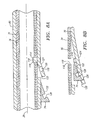
- the outer sleeve 45 may include weakened regions, e.g., longitudinal slots or perforations 45a or thin walled regions (not shown), that may be torn, expanded, and/or enlarged during advancement of the carrier and pusher members 40, 42 relative to the outer sleeve 34, as explained further below.
- the outer sleeve 45 may include a plurality of longitudinal slots 45a with circumferentially adjacent slots being staggered longitudinally from one another, as shown in FIG. 6C. This slot arrangement may facilitate the outer sleeve 45 expanding or being deflected out of the way upon advancing the carrier and pusher members 40, 42 without fully exposing the clip 5, as explained further below.
- the longitudinal slots maybe spiral slots 45a' formed in the outer sleeve 45,' Spiral slots 45a' may minimize tissue moving as the carrier assembly 14 is advanced through tissue (not shown), as described further below.
- a substantially flexible sleeve or skin may be provided that extends over the space 15, similar to the outer sleeve 45, but that may be bonded or otherwise secured to the outer surface of the introducer sheath 12.
- Embodiments of such a skin may be found in co-pending application Serial No. 10/081,725, filed on the same day as the present application and entitled "Sheath Apparatus and Methods for Delivering a Closure Device," which is assigned to the assignee of the present application.
- the disclosure of this application and any references cited therein are expressly incorporated herein by reference.
- the disclosure of this application and any references cited therein are expressly incorporated herein by reference.
- the carrier, pusher, and anchor members 40, 42, 44 are coaxially disposed with respect to one another such that they telescope at least partially within one another.
- the tongues 50, 60, 70 preferably overlap and/or are coextensive with one another, as shown in FIG. 6B).
- the tabs (only tab 72 is shown in FIG. 6B) may also be aligned with one another.
- Each of the tongues 50, 60, 70 is preferably tapered to facilitate attachment of the actuator assembly 16, as described further below.
- the tongues 50, 60, 70 may include holes 51, 61, 71 that may be aligned with one another when the carrier, pusher, and anchor members 40, 50, 60 are aligned within one another.
- the holes 51, 61, 71 may be sized for receiving a pin 240 (not shown, see FIGS. 3A and 4), or an alignment detent (not shown) for ensuring that the carrier, pusher, and anchor members 40, 50, 60 are properly aligned over one another before using the apparatus 10.
- the carrier assembly 14 may be used to deploy a clip 5 or other closure element from the space 15 defined by the carrier assembly 14.
- the clip 5 is a generally annular-shaped clip, including one or more barbs and/or tines 7 for engaging the tissue around an opening, e.g., in or adjacent to a wall of a blood vessel (not shown).
- the clip 5 is configured for drawing the tissue around a puncture in the wall of the vessel substantially closed and/or for enhancing hemostasis within the puncture.
- Exemplary embodiments of a closure element are disclosed in U.S. Patent No. 6,197,042, in co-pending applications Serial Nos. 09/546,998 and 09/610,238, and in co-pending application Serial No. 10/081,726, filed on the same day as the present application, and titled "Closure Apparatus and Methods for Making and Using Them.” The disclosures of these references and any others cited therein are expressly incorporated herein by reference.
- the carrier assembly 14 is actuable from the proximal end 22 of the sheath 12, preferably by the actuator assembly 16.
- the carrier assembly 14 maybe substantially permanently, but slidably, disposed on the sheath 12.
- the carrier assembly 14 may be initially stored at least partially within the passage 38 under the hub 30, e.g., under the strain relief nose 226.
- the carrier assembly 14 may be provided separate as a separate assembly (not shown), e.g., with the clip 5 pre-loaded therein, that may be slidably received on the sheath 12.
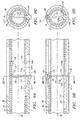
- the actuator assembly 16 generally includes a handle body or housing 74 and a plurality of telescoping actuator members 76, 78, 80.
- the housing 74 includes mating handle covers 74a, 74b, and a nose cover 75 within which the actuator members 76, 78, 80 are slidably mounted.
- the handle body 74 may include one or more cooperating connectors for connecting the actuator assembly 16 to the sheath 12.
- the nose cover 75 may include pockets 84 (see FIG. 1) for receiving tabs 34 on the hub assembly 30.
- the actuator assembly 16 may be substantially permanently attached to the sheath 12, as described further below.
- the actuator assembly 16 may include a frame subassembly 190, and side plates 191, which may secure the obturator assembly 18 relative to the housing 74, as explained further below.
- the telescoping actuator members 76, 78, 80 include an inner tubular member 76, an intermediate tubular member 78, and an outer tubular member 80.
- the actuator members 76-80 are substantially rigid members having longitudinal slots 86, 88, 90 therein, thereby defining generally "C" shaped cross-sections over at least a substantial portion of their lengths.
- Each of the longitudinal slots 86, 78, 90 may have a width similar to a width of the tongues 50, 60, 70 on the carrier assembly 14, as described further below.
- the longitudinal slots 86, 78, 90 extend predetermined distances from distal ends 92, 94, 96 of the respective tubular members 76, 78, 80 towards, but not necessarily completely to, their proximal ends (not shown).
- the distal ends 92, 94, 96 include detents for engaging respective detents on the carrier assembly 14.
- the detents may be pockets 104, 106, 108 including a tapered proximal edge and a substantially blunt distal edge (only edges 108a, 108b are shown and labeled in FIG. 7B), similar to the respective tabs 52, 62, 72 on the carrier, pusher, and anchor members 40, 42, 44.
- movement of the carrier, pusher, and anchor members 40, 42, 44 may be coupled to the inner, intermediate, and outer actuator members 76, 78, 80, respectively, when the tongues 50, 60, 70 are received in the slots 86, 88, 90.
- the actuator assembly 16 also includes a control member, such as knob 110 and shaft 112, that are coupled to the inner, intermediate, and/or outer actuator members 76, 78, 80.
- a control member such as knob 110 and shaft 112 that are coupled to the inner, intermediate, and/or outer actuator members 76, 78, 80.
- the shaft 112 is connected only to the intermediate actuator member 78.
- axial movement of one or more of the actuator members 76, 78, 80 may be attained by applying an axial force to the knob 110.
- the inner, intermediate, and outer actuator members 76-80 include one or more sets of cooperating detents for coupling distal movement of the inner, intermediate, and outer actuator members 76-80 in a predetermined manner, as the knob 110 is directed distally.
- detents refers to any combination of mating elements, such as tabs, pockets, slots, ramps, cantilevered members, and the like, that may be selectively or automatically engaged and/or disengaged to couple or decouple the actuator members 76-80 relative to one another.
- the cooperating detents described below are merely exemplary and not exhaustive.
- the cooperating detents include a first set of cooperating detents for releasably coupling the outer tubular member 80 to the inner and intermediate tubular members 76, 78.
- the outer tubular member 80 may be decoupled and preferably anchored from further substantial axial movement.
- the inner and intermediate tubular members 76, 78, and consequently the carrier and pusher members 40, 42 may continue to be directed distally, while the outer tubular member 80 and the sheath member 44 remain anchored in place.
- FIGS. 8A and 8B show a preferred embodiment of a first set of cooperating detents for releasably coupling the outer tubular member 80 to the inner and intermediate tubular members 76, 78.
- the outer tubular member 80 includes a first detent or tab 114 (or optionally multiple detents, not shown) and the inner and intermediate tubular members 76, 78 include first pockets 116, 118 for receiving the first tab 114 therein.
- any axial force (in either direction) moving one of the tubular members 76-80 moves all of them.
- First and second ramps 120, 122 are provided on the outer tubular member 80 and the housing 74 of the actuator assembly 16 (only a portion of which is shown) of the sheath 12 (not shown).
- the first and second ramps 120, 122 slidably engage one another as the actuator members 76, 78, 80 and/or the carrier assembly 14 (not shown) reach the first distal position.
- the second ramp 122 maybe provided on a portion of the hub assembly 30 (not shown).
- the first ramp 120 on the outer tubular member 80 defines a free end of a first cantilevered beam 124 from which the first tab 114 extends inwardly.
- the beam 124 includes a hole 126 therethrough and the second ramp 122, which is relatively stationary, includes a recess or other feature 128 therein.
- the actuator members 76, 78, 80 may be advanced distally (in direction of arrow) until the cooperating first and second ramps 120, 122 slidably engage one another. As the actuator members 76, 78, 80 are advanced further distally, the first ramp 120 slides up onto the second ramp 122, thereby deflecting the first beam 124 outwardly until the first tab 114 is disengaged from the first pockets 116, 118, as shown in FIG. 8B.
- a surface 129 in the hole 126 on the flange 124 and the feature 128 in the second ramp 122 preferably interlock or otherwise contact one another, This contact may secure the outer tubular member 80 from subsequent axial movement, while still allowing the inner and intermediate tubular members 76, 78 to be directed distally beyond the first distal position.
- the actuator assembly 16 may include a second set of cooperating detents for releasably coupling the inner tubular member 76 and the intermediate tubular member 78 and/or recoupling the inner and outer tubular members 76, 80.
- the inner and intermediate tubular members 76, 78 may be directable to a second distal position distal to the first distal position (while the outer tubular member 80 remains substantially stationary).
- the cooperating detents may decouple the intermediate tubular member 78 from the inner tubular member 76 and/or anchor the inner tubular member 76 in place, e.g., relative to the outer tubular member 80.
- the intermediate tubular member 78, and consequently the pusher member 42 may then be advanced further distally beyond the second distal position, as described further below.
- an exemplary second set of cooperating detents includes a second tab or other detent 130 on the intermediate tubular member 78 and a second pocket 132 in the inner tubular member 76.
- the second tab 130 may be received in the second pocket 132 for coupling movement of the inner and intermediate tubular members 76, 78 together.
- the outer tubular member 80 includes a spring element 138 that is configured for disengaging the second tab 130 from the second pocket 132 upon attaining the second distal position.
- the spring element 138 may include a transverse beam 140 that extends from a third cantilevered beam 141 on the outer tubular member 80.
- the transverse beam 140 extends through slots 142, 144 in the inner and intermediate tubular members 76, 78, e.g., transversely to the longitudinal axis 28, and preferably substantially perpendicular to the longitudinal axis 28.
- the transverse beam 140 has an inverted "T" shape, as best seen in FIGS. 9C and 9D, defining one or more shoulders 146 adjacent a stem 148.
- the slots 142, 144 may have narrow regions 142a, 144a and wide regions 142b, 144b proximal to the narrow regions 142a, 144a.
- the narrow regions 142a, 144a have a width less than the shoulders 146, but wider than the stem 148.
- the wide regions 142b, 144b have a width greater than a width of the shoulders 146.
- narrow regions 142a, 144a and wide regions 142b, 144b are disposed along the longitudinal axis 28 at predetermined locations such that the transverse beam 140 coincides with the wide regions 142b, 144b approximately at the second distal position.
- the shoulders 146 may slide along the outer surface of the intermediate tubular member 78 while the stem 148 slides inside the narrow region 142a, 144a of the slots 142, 144. Alternatively, the shoulders 146 may slide along an outer surface (not shown) of the inner member 76 if the slot 144 is wide its entire length.
- the tip 150 of the transverse beam 140 may move along the inner tubular member 76, e.g., at a predetermined clearance from the inner surface thereof such that the tip 150 does not touch the inner surface of the inner tubular member 76. Alternatively, the tip 150 may slide along the inner surface of the inner tubular member 76.
- the shoulders 146 may enter the wide regions 142b, 144b, e.g., due to the bias of the beam 141. This action may produce two substantially simultaneous results. First, when the shoulders 146 enter the wide regions 142b, 144b, i.e., such that the beam 140 moves transversely, the tip 150 of the beam 140 may push the second tab 130 radially outward, thereby disengaging the second tab 130 from the second pocket 132. Thus, further distal movement of the intermediate tubular member 78 may be allowed independent of the inner tubular member 76. In addition, the shoulders 146 of the beam 140 may enter the wide region 142b of the slot 142. Because the wide region 142b has a size corresponding substantially to a cross-section of the transverse beam 140, the inner tubular member 76 is consequently coupled to the outer tubular member 80 as it is disengaged from the intermediate tubular member 78.
- the inner tubular member 76 may be substantially locked in place, e.g., to the outer tubular member 80 since the outer tubular member 80 has been previously secured in place.
- these two actions i.e., releasing the intermediate tubular member 80 and securing the inner tubular member 76 in place occur substantially simultaneously.
- the actuator assembly 16 also includes the obturator assembly 18 mounted within the housing 74.
- the obturator assembly 18 includes a flexible or semi-rigid tubular body or other elongate rail 172 having a proximal end 174, a distal end 176, and a distal portion 184.
- An actuator rod, wire, or other elongate member 178 is slidably disposed with respect to the rail 172, e.g., within a lumen of the rail 172.
- the obturator assembly 18 includes an obturator housing 180 on the proximal end 174 of the rail 172.
- the obturator housing 180 may include one or more tabs 192 for engaging complementary slots 194 in the side plates 191.
- the obturator assembly 18 maybe secured within the housing 74 of the actuator assembly 16 when the tabs 192 are received in the slots 194.
- the side plates 191 may be connected to the frame subassembly 190, and the handle covers 74a, 74b are secured over the side plates 191.
- the rail 172 may extend through the actuator members 76, 78, 80, e.g., until the distal portion 182 extends beyond the distal ends 92, 94, 96 of the actuator members 76, 78, 80.
- the distal portion 182 of the obturator assembly 18 includes a substantially rounded, soft, and/or flexible distal tip 184.
- the distal tip 184 may include a pigtail (not shown) that may facilitate atraumatic advancement of the distal portion 182 into a blood vessel or other body lumen (not shown).
- the obturator assembly 18 preferably has a length relative to the sheath 12 such that the distal portion 182 extends beyond the distal end 24 of the sheath 12 when the obturator assembly 18 is in a deployed position (shown in FIGS. 12C and 12D), as explained below.
- One or more, and preferably a plurality of, positioning elements 186 are provided on the distal portion 182 that may be selectively expandable between a substantially axial collapsed configuration (shown in FIG. 10A) and a substantially transverse expanded configuration (shown in FIG. 10B).
- the positioning elements 186 are substantially flexible splines configured for expanding substantially transversely with respect to the longitudinal axis 28.
- the obturator assembly 18 includes four splines 186 that are substantially equally spaced about the distal portion 182.
- the obturator assembly 18 may include a pair of splines (not shown) that are disposed generally opposite one another about the distal portion.
- the obturator assembly 18 may include more or fewer splines without deviating from the scope of the present invention. Additional embodiments of positioning elements are disclosed in co-pending application Serial No. 09/732,835, the disclosure of which is expressly incorporated herein by reference.
- the splines 186 may include radiopaque markers (not shown) or may be wholly or partially formed from radiopaque material to facilitate observation of the splines 186 using fluoroscopy or other imaging systems.
- the carrier assembly 14 may include one or more radiopaque markers, e.g., at its distal end (not shown) and/or the clip 5 may include radiopaque marker(s) or may be made from radiopaque material. This may facilitate monitoring the location of the clip 5 relative to the splines 186, as described further below.
- each spline 186 preferably has a first fixed (e.g., proximal) end 186a and a second movable (e.g., distal) end 186b.
- the second end 186b may be axially movable towards the first end 186a to cause an intermediate region 186c of the spline 186 to buckle and/or expand transversely outwardly, thereby defining the substantially transverse expanded configuration.
- an actuator rod 178 extends through the distal portion 182 and is coupled to the distal tip 184 of the obturator assembly 18 and/or to one of the first and second ends 186a, 186b.
- the actuator rod 178 may be moved axially, e.g., proximally, with respect to the rail 172 to selectively expand the splines 186 between their collapsed configuration and their expanded configuration.
- the obturator housing 180 (not shown, see FIG. 3A) is configured for selectively deploying the distal portion 182 and/or moving the splines 186 between their collapsed and expanded configurations.
- the obturator housing 180 may include a switch 188 that may be depressed or rotated. Initially, as shown in FIG. 12B, the distal portion 182 may be retracted within the distal end 24 of the sheath 12. As the switch 188 is activated, e.g., depressed, the distal portion 182 may be deployed from the distal end 24 of the sheath 12, as shown in FIG. 12C. As the switch is further depressed, the splines 186 may be expanded to the expanded configuration, as shown in FIG. 12D.
- the rail 172 and rod 178 may initially be moved together, e.g., to deploy the distal portion 182, as shown in FIG. 12C. Once deployed, the rod 178 may stop moving, the rail 172 may continue to advance, thereby buckling the splines 186 as the first and second ends 186a, 186b become closer to one another, as shown in FIG. 12D. Alternatively, after deploying the distal portion 182, the rod 178 may be retracted proximally to expand the splines 186.
- the obturator housing 180 (not shown, see FIG. 3A) preferably includes a lock (not shown) for securing the rod 178 and rail 172 relative to one another, e.g., to lock the splines 186 in their expanded configuration.
- the lock may be released, for example, by depressing the switch 188 again, by activating an emergency release (not shown) and/or by activating a release mechanism (not shown) when the carrier assembly 14 is advanced, as explained below.
- the obturator housing 180 may include a spring or other biasing mechanism (not shown) for biasing the rail 172 and/or rod 178 to return the splines 186 to their collapsed configuration and/or to retract the distal portion 182 back into the sheath 12 when the lock is released.
- the lock may be released upon advancing the actuator members 76, 78, 80 to a predetermined position, e.g., before or after attaining the second distal position, as explained further below.
- an apparatus 310 for delivering a closure element 5 may be provided that includes a separate obturator assembly 318 that may be inserted into or otherwise connected to an actuator assembly 316.
- the actuator assembly 316 may include a lateral port 352 with an inner passage 354 that communicates with an interior region or lumen (not shown) of actuator members 376-380 of the actuator assembly 316.
- the obturator assembly 318 may be inserted into the lateral port 352, thereby introducing a distal portion 382 of the obturator assembly 318 into the sheath 312.
- An obturator housing 381 of the obturator assembly 318 may include one or more detents (not shown) for engaging complementary-shaped detents (also not shown) on the lateral port 352.
- the obturator assembly 318 may be substantially secured axially with respect to the lateral port 352, and consequently relative to the actuator assembly 316 and sheath 312. Otherwise, the actuator and obturator assemblies 316, 318 may operate similar to the previous embodiment.
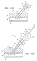
- an apparatus 10 (the entire apparatus 10 is shown in FIGS. 12B-12F), such as that shown in FIG. 1, may be used to deliver a closure device, such as a clip 5, to close and/or seal an incision, puncture, or other opening.
- a closure device such as a clip 5
- the apparatus 10 may be used to deliver the clip 5 through a passage 92 that extends from a patient's skin 94, through intervening tissue 96, and into a wall 98 of a blood vessel 90.
- the apparatus 10 maybe used to deliver other annular shaped devices (not shown) that may be disposed within the carrier assembly 14.
- the sheath 12 may be inserted or otherwise positioned within the blood vessel 90, i.e., through the passage 92.
- the sheath 12 is preferably provided with the carrier assembly 14 in its proximal position, e.g., adjacent to or within the hub assembly 30.
- the sheath 12 may be advanced over a guide wire or other rail (not shown) previously positioned through the passage 92 into the blood vessel 90 using conventional procedures.
- the blood vessel 90 is a peripheral vessel, such as a femoral or carotid artery, although other body lumens may be accessed using the sheath 12, as will be appreciated by those skilled in the art.
- the passage 92, and consequently the sheath 12 may be oriented with respect to the vessel 90, thereby facilitating introduction of devices through the lumen 20 of the sheath 12 into the vessel 90 with minimal risk of damage to the vessel 90.
- One or more devices such as a guide wire, a catheter, and the like (not shown), may be inserted through the sheath 12 and advanced to a desired location within the patient's body.
- the devices may be used to perform a therapeutic or diagnostic procedure, such as angioplasty, atherectomy, stent implantation, and the like, within the patient's vasculature.
- the device(s) may be removed from the sheath 12, and the actuator assembly 16 may be attached to the hub assembly 30 of the sheath 12.
- the longitudinal slots 86-90 in the actuator members 76, 78, 80 may be aligned with the side port 36 extending from the hub assembly 30. This may align the "C" shaped cross-sections of the tubular members 76-80 with the spoke (not shown) extending across the passage 38.
- the distal portion 182 of the obturator assembly 18 may then be inserted into the lumen 20 of the sheath 12, and advanced towards the distal end 24 of the sheath 12.
- the actuator members 76, 78, 80 may also be inserted into the passage 38, thereby disposing the distal portion 182 in a predetermined rotational orientation relative to the sheath 12.
- the carrier assembly 14 is also disposed at least partially within the passage 38 (not shown in FIGS. 7A and 7B) such that the tongues 50, 60, 70 on the carrier, pusher, and anchor members 40, 42, 44 are aligned with the side port 36. Consequently, the tongues 50, 60, 70 may be aligned with the longitudinal slots 86, 88, 90 in the actuator members 76, 78, 80 as the actuator members 76, 78, 80 are inserted into the passage 38.
- the tongues 50, 60, 70 maybe received in the longitudinal slots 86, 88, 90, preferably until the tabs 52, 62, 72 are received in the pockets 104, 106, 108, as best seen in FIG. 7B.
- the tongues 50, 60, 70 are preferably at least partially tapered, thereby self-aligning with the longitudinal slots 86, 88, 90, e.g., to correct any slight misalignment.
- the carrier, pusher, and sheath members 40, 42, 44 may be coupled to the inner, intermediate, and outer tubular members 76, 78, 80, respectively.
- the distal portion 182 of the obturator assembly 16 is preferably disposed adjacent the distal end 24 of the sheath 12 within the lumen 20, as best seen in FIG. 12B.
- the actuator assembly 316 may be attached to the hub assembly 330 without the obturator assembly 318.
- the obturator assembly 318 may then be inserted into the lateral port 352, through the interior of the actuator members 376-380, and into the lumen 320 of the sheath 312 at any time before deploying the clip 5.
- the distal portion 382 of the obturator assembly 318 may be disposed adjacent the distal end 324 of the sheath 312, similar to the actuator assembly 16.
- the distal portion 182 of the obturator 18 may be advanced beyond the distal end 24 of the sheath 12, for example, by depressing the switch 188 on the actuator assembly 16.
- the distal tip 184 preferably is substantially soft and/or flexible such that the distal portion 182 substantially atraumatically enters the vessel 90.
- cooperating detents (not shown), e.g., on the actuator housing 180 and the rail 172 of the actuator assembly 16, may be engaged to substantially secure the distal end 182 of the obturator 18 beyond the distal end 24 of the sheath 12.
- the splines 186 may then be directed to their expanded configuration, for example, by further depressing the switch 188 on the actuator assembly 16.
- the distal portion 182 is deployed and the splines are expanded in a single motion, e.g., by activating the switch 188.
- these steps may be performed independently from one another if desired.
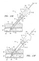
- the entire apparatus 10, including the sheath 12 and splines 186 may then be moved, e.g., by manipulating the actuator assembly 16.
- the apparatus 10 is partially withdrawn from the vessel 90 until the splines 186 contact the wall 98 of the vessel 90, as shown.
- the splines 186 may provide a tactile indication of the position of the distal end 24 of the sheath 12 with respect to the wall 98 of the vessel 90.
- the splines 186 may assist in "presenting" the wall 98 of the vessel 90, e.g., for receiving the clip 5 (or other closure element) if the clip 5 is to engage the wall 98.
- the carrier assembly 14 may be advanced along the sheath 12, i.e., into the passage 92 to deliver the clip 5. For example, a distal force may be applied to the knob 110, thereby advancing the actuator members 76, 78, 80 and consequently the carrier assembly 14 distally over the sheath 12. Because the actuator members 76, 78, 80 are all coupled together, as described above, the carrier assembly 14 advances with the outer sleeve 45 on the anchor member 44 substantially covering the clip 5. Because of the tapered configuration of the outer sleeve 45 and the carrier member 40, the carrier assembly 14 may be advanced through the passage 92 substantially atraumatically.
- the tissue surrounding the passage 92 may not be exposed to the tines 7 on the clip 5, which otherwise may inadvertently catch the tissue and damage the tissue and/or the clip 5.
- the outer sleeve 45 may facilitate advancing the carrier assembly 14 through intervening layers of tissue, such as one or more layers of fascia (not shown) that may be encountered between the skin 94 and the wall 98 of the vessel 90.
- the first set of cooperating detents (not shown, but described above with reference to FIGS. 8A and 8B) are disengaged to release the outer tubular member 80 with respect to the inner and intermediate tubular members 76, 78.
- the first beam 124 on the outer tubular member 80 may slidably engage the second ramp 122 on the housing 74, thereby disengaging the first tab 114 from the first pockets 116, 118.
- the outer tubular member 80 is preferably substantially secured at the first distal position, e.g., when the hole 126 in the first beam 124 interlocks a recess 128 in the second ramp 122 (as shown in FIG. 8B).
- the inner and intermediate tubular members 76, 80, and consequently the carrier and pusher members 40, 42 may be advanced further distally.
- the carrier and pusher members 40, 42 may cause the outer sleeve 45 to expand to accommodate their advancing between the outer sleeve 45 and the sheath 12.
- the outer sleeve 45 may include longitudinal slots, e.g., either straight slots 45a, as shown in FIG. 6C, or spiral slots 45a,' as shown in FIG. 6D.
- the slots 45a, 45a' may open as the carrier and pusher members 40, 42 are advanced, such that the outer sleeve 45 expands to assume a zigzag mesh configuration.
- the spiral slots 45a' may translate axial forces to torsional forces due to the spiral shape of the slots 45a,' e.g., such that the outer sleeve 45' twists as it expands, causing the surrounding tissue 96 to rotate about the longitudinal axis 28, thereby minimizing the tissue 96 being pushed distally as the carrier and pusher members 40, 42 are advanced through the tissue 96.
- the second set of cooperating detents interact to release the intermediate tubular member 78 from the inner tubular member 76.
- the transverse beam 140 may push the second tab 130 out of the second pocket 132 (as best seen in FIG. 9B).
- the second set of detents also preferably substantially secure the inner tubular member 76, e.g., by interlocking the transverse beam 140 in the wide portion 142b of slot 142.
- the intermediate tubular member 78 may then be advanced further distally by continuing to apply a distal force to the knob 110 (not shown).
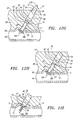
- the pusher member 42 may be advanced distally relative to the carrier member 40, thereby forcing the clip 5 distally off the carrier member 40 and preferably into engagement with the wall 98 of the vessel 90 or other tissue surrounding the passage 92.
- the splines 186 may automatically return to their collapsed configuration and/or may be retracted into the sheath 12 during deployment of the clip 5.
- the splines 186 may be collapsed as the clip 5 is partially deployed from the carrier assembly 14, e.g., before the clip 5 is completely collapsed towards its closed position.
- the orientation of the clip 5 and the splines 186 about the longitudinal axis 28 may be such that tines 7 of the clip 5 are disposed between the splines 186 as the clip 5 is deployed.
- the tines 7 may avoid being driven into the splines 186.
- Embodiments of a clip and delivery apparatus that provide such an orientation are disclosed in application Serial No. 10/081,726, incorporated by reference above.
- the intermediate tubular member 78 may release the lock in the obturator housing 180, thereby causing the splines 186 to collapse and/or the distal portion 182 to retract into the sheath 12.
- the splines 186 may be collapsed before the clip 5 is ejected completely from off of the carrier member 40, or even before the pusher member 42 begins to deploy the clip 5. This may avoid any risk of contact between the clip 5 and the splines 186.
- the relative lengths of the actuator members 76, 78, 80 and the sheath 12 and/or the length of the longitudinal slots 86, 88, 90 may be set such that the second distal position is at a region proximal to the wall 98 of the vessel 90.
- the clip 5 may be deployed such that the tines 7 are driven into or through the wall 98 of the vessel 90.
- the apparatus 10 may be withdrawn from the passage 92. If the splines 64 of the locator member 14 are not automatically collapsed during advancement of the housing 24, the splines 64 may be affirmatively collapsed, e.g., by depressing the switch 188. The entire apparatus 10 may then be removed in one step. Alternatively, as in the embodiment of FIGS. 11A and 11B, if the obturator assembly 318 is separable from the actuator assembly 316, it may be withdrawn from the sheath 12 before withdrawing the actuator assembly 316 and/or sheath 312.
- the clip 5 remains in place within the wall 98 of the vessel 90 or in the surrounding tissue 96 adjacent the vessel 90 to close and/or seal the passage 92.
- the clip 5 may remain substantially permanently in the patient's body.
- the clip 5 may be formed from bioabsorbable material, and may remain until the passage 92 is at least partially healed and the clip 5 is absorbed by the surrounding tissue 96.
Abstract
Description
Claims (21)
- Apparatus for delivering a closure device (10) having an obturator configured to be positioned within a vessel, comprising:an elongated rail (172) having a proximal end (174) and a distal end (176);at least one or more positioning elements (186), the positioning element (186) having a proximal end (186a), a distal end (186b) and an intermediate portion (186c); andan actuator rod (178) slidably disposed with respect to the rail (172) and coupled to one of the ends (186a, 186b) of the positioning elements (186), wherein movement of the actuator rod (178) relative to the rail (172) causes the intermediate portion (186c) to buckle outwardly.
- The apparatus (10) according to claim 1, wherein at least one of the positioning elements includes a radiopaque marker.
- The apparatus (10) according to claim 1, wherein the positioning elements are equally spaced radially about the distal end (176) of the rail (172).
- The apparatus (10) according to claims 1 and 3, further comprising a locking mechanism associated with the actuator rod (178) wherein the locking mechanism is configured to secure the actuator rod (178) and rail (172) relative to one another.
- The apparatus (10) according to claim 1, wherein the position elements (186) are splines.
- The apparatus (10) according to claim 1, wherein there are at least four positioning elements (186).
- The apparatus (10) according to claim 1, wherein the rail (172) comprises a semi-rigid tubular body.
- The apparatus (10) according to claim 1, wherein the positioning elements buckle outwardly extending substantially transversely with respect to a longitudinal axis (28) of the apparatus (10).
- An apparatus (10) for delivering a closure element into an opening through tissue, comprising:an elongate member (12) comprising proximal and distal ends (22,24);a carrier assembly (14) slidable on the elongate member (12), the carrier assembly (14) comprising an inner carrier member (40), a middle pusher member (42), and an outer sleeve member (44,45), each member comprising an annular body (32,54,64) including a connector (52,62,72) on its proximal end (46,56,66) the pusher member (42) disposed about the carrier member (40), thereby defining a space (15) distal to the pusher member (42) along an outer surface of the carrier member (40), the outer sleeve member (44,45) extending at least partially over the space (15); andan annular-shaped element (5) received on the carrier member (40) within the space (15), the annular-shaped element (5) being deployable from the space (15) upon distal movement of the pusher member (42) relative to the carrier member (40).
- The apparatus (10) of claim 9 further comprising an actuator assembly (16) comprising an actuator housing (74) and inner, intermediate, and outer actuator members (76,78,80) that telescope relative to the actuator housing (74), the actuator housing (74) extending from the proximal end (22) of the elongate member (12), each actuator member comprising a connector (104,106,108) on its distal end (92,94,96) for engaging a respective connector (52,62,72) on the carrier assembly (14), thereby coupling movement of the carrier pusher, and outer sleeve members (40,42,44) to the inner, intermediate, and outer actuator members (76,78,80), respectively.
- The apparatus (10) of claim 10 wherein the actuator assembly (16) comprises a control member (110,112), and the inner, intermediate, and outer actuator members (76,78,80) comprise a first set of cooperating detents (116,118,114) for coupling distal movement of the inner, intermediate, and outer actuator members (76,78,80) as the control member (110,112) is directed distally, the first set of cooperating detents (116,118,114) releasing the outer actuator member (80) upon attaining a first distal position, thereby permitting further distal movement of the inner and intermediate actuator members (76,78), and consequently permitting the carrier and pusher members (40,42) to be directed distally beyond the outer sleeve member (44,45).
- The apparatus (10) of claim 11 wherein the control member (110,112) is coupled to one of the inner actuator member (76) and the intermediate actuator member (78), and wherein the first set of cooperating detents (116,118,114) comprise a first detent (114) on the outer actuator member (80) and first pockets (116,118) in the inner and intermediate actuator members (76,78) for receiving the first detent (114) therein, the apparatus further comprising cooperating ramps (120,122) on at least one of the actuator housing (74) and the outer actuator member (80), the cooperating ramps (120,122) being configured for disengaging the first detent (114) from the first pockets (116,118) upon attaining the first distal position, thereby allowing the inner and intermediate actuator members (76,78) to be directed distally beyond the first distal position.
- The apparatus (10) of claim 11 further comprising a second set of cooperating detents (130,132) on the intermediate actuator member (78) and the inner actuator member (76) for coupling movement of the inner and intermediate actuator members (76,78) together.
- The apparatus (10) of claim 13 wherein the second set of cooperating detents comprises a second detent (130) on the intermediate actuator member (78) and a second pocket (132) on the inner actuator member (76).
- The apparatus (10) of claim 14 wherein the inner and intermediate actuator members (76,78) are directable to a second distal position distal to the first distal position, and wherein one of the actuator housing (74) and the outer actuator member (80) comprises a spring element (138) for disengaging the second detent (130) from the second pocket (132) upon attaining the second distal position.
- The apparatus (10) of claim 15 wherein the control member (110,112) is coupled to the intermediate actuator member (78), and wherein the intermediate actuator member (78) may be advanced distally beyond the second distal position by directing the control member (110,112) further distally, thereby directing the pusher member (42) distally with respect to the carrier member (40) to deploy the annular-shaped element (5) from the space (15).
- The apparatus (10) of claim 10 further comprising:a locator member (18) connected to the actuator assembly (16), the locator member having a distal portion (182) extendable distally beyond the distal end (24) of the elongate member (12)one or more positioning elements (186) on the distal portion (182) of the locator member (18) the positioning elements (186) being expandable from a collapsed configuration towards a transversely expanded configuration; anda locking mechanism on the locator member (18) for releasably retaining the positioning elements (186) in the expanded configuration.
- The apparatus (10) of claim 17 wherein the elongate member (12) comprises an introducer sheath, and the locator member (18) comprises an obturator insertable into a lumen (20) of the sheath.
- The apparatus of claim 18 wherein the obturator is insertable into the actuator housing (74) and into the lumen (20) of the sheath until the positioning elements (186) are disposed beyond the distal end (24) of the sheath.
- The apparatus (10) of claim 9 wherein the annular-shaped member (5) comprises a closure element including a plurality of tissue engaging elements oriented distally along the outer surface of the carrier member (40).
- The apparatus (10) of claim 9, wherein at least one of the carrier member (40) and the pusher member (42) is slidable distally relative to the outer sleeve member (44,45), the outer sleeve member being expandable to accommodate at least one of the carrier member (40) and the pusher member (42) sliding between the outer sleeve member (44,45) and the outer surface of the elongate member (12).
Applications Claiming Priority (3)
| Application Number | Priority Date | Filing Date | Title |
|---|---|---|---|
| US10/081,723 US6942674B2 (en) | 2000-01-05 | 2002-02-21 | Apparatus and methods for delivering a closure device |
| US81723 | 2002-02-21 | ||
| EP03709193A EP1478280B1 (en) | 2002-02-21 | 2003-02-18 | Apparatus for delivering a closure device |
Related Parent Applications (2)
| Application Number | Title | Priority Date | Filing Date |
|---|---|---|---|
| EP03709193A Division EP1478280B1 (en) | 2002-02-21 | 2003-02-18 | Apparatus for delivering a closure device |
| EP03709193.1 Division | 2003-02-18 |
Publications (3)
| Publication Number | Publication Date |
|---|---|
| EP1595505A2 true EP1595505A2 (en) | 2005-11-16 |
| EP1595505A3 EP1595505A3 (en) | 2006-04-26 |
| EP1595505B1 EP1595505B1 (en) | 2009-08-19 |
Family
ID=27765265
Family Applications (2)
| Application Number | Title | Priority Date | Filing Date |
|---|---|---|---|
| EP05106654A Expired - Fee Related EP1595505B1 (en) | 2002-02-21 | 2003-02-18 | Apparatus for delivering a closure device |
| EP03709193A Expired - Fee Related EP1478280B1 (en) | 2002-02-21 | 2003-02-18 | Apparatus for delivering a closure device |
Family Applications After (1)
| Application Number | Title | Priority Date | Filing Date |
|---|---|---|---|
| EP03709193A Expired - Fee Related EP1478280B1 (en) | 2002-02-21 | 2003-02-18 | Apparatus for delivering a closure device |
Country Status (5)
| Country | Link |
|---|---|
| US (2) | US6942674B2 (en) |
| EP (2) | EP1595505B1 (en) |
| AU (1) | AU2003213147A1 (en) |
| DE (2) | DE60301664T2 (en) |
| WO (1) | WO2003071956A2 (en) |
Families Citing this family (736)
| Publication number | Priority date | Publication date | Assignee | Title |
|---|---|---|---|---|
| US7842068B2 (en) | 2000-12-07 | 2010-11-30 | Integrated Vascular Systems, Inc. | Apparatus and methods for providing tactile feedback while delivering a closure device |
| US6461364B1 (en) | 2000-01-05 | 2002-10-08 | Integrated Vascular Systems, Inc. | Vascular sheath with bioabsorbable puncture site closure apparatus and methods of use |
| US6780197B2 (en) * | 2000-01-05 | 2004-08-24 | Integrated Vascular Systems, Inc. | Apparatus and methods for delivering a vascular closure device to a body lumen |
| US8758400B2 (en) | 2000-01-05 | 2014-06-24 | Integrated Vascular Systems, Inc. | Closure system and methods of use |
| US9579091B2 (en) | 2000-01-05 | 2017-02-28 | Integrated Vascular Systems, Inc. | Closure system and methods of use |
| US6391048B1 (en) | 2000-01-05 | 2002-05-21 | Integrated Vascular Systems, Inc. | Integrated vascular device with puncture site closure component and sealant and methods of use |
| US6942674B2 (en) | 2000-01-05 | 2005-09-13 | Integrated Vascular Systems, Inc. | Apparatus and methods for delivering a closure device |
| US9522217B2 (en) | 2000-03-15 | 2016-12-20 | Orbusneich Medical, Inc. | Medical device with coating for capturing genetically-altered cells and methods for using same |
| US8088060B2 (en) | 2000-03-15 | 2012-01-03 | Orbusneich Medical, Inc. | Progenitor endothelial cell capturing with a drug eluting implantable medical device |
| ES2435094T3 (en) | 2000-05-19 | 2013-12-18 | C.R. Bard, Inc. | Device and method of tissue capture and suturing |
| AU8800801A (en) | 2000-09-08 | 2002-03-22 | James E Coleman | Surgical staple |
| US6626918B1 (en) | 2000-10-06 | 2003-09-30 | Medical Technology Group | Apparatus and methods for positioning a vascular sheath |
| US7211101B2 (en) | 2000-12-07 | 2007-05-01 | Abbott Vascular Devices | Methods for manufacturing a clip and clip |
| US6695867B2 (en) | 2002-02-21 | 2004-02-24 | Integrated Vascular Systems, Inc. | Plunger apparatus and methods for delivering a closure device |
| US7905900B2 (en) | 2003-01-30 | 2011-03-15 | Integrated Vascular Systems, Inc. | Clip applier and methods of use |
| US8690910B2 (en) | 2000-12-07 | 2014-04-08 | Integrated Vascular Systems, Inc. | Closure device and methods for making and using them |
| US7806904B2 (en) | 2000-12-07 | 2010-10-05 | Integrated Vascular Systems, Inc. | Closure device |
| US6623510B2 (en) | 2000-12-07 | 2003-09-23 | Integrated Vascular Systems, Inc. | Closure device and methods for making and using them |
| US6723037B2 (en) * | 2000-12-15 | 2004-04-20 | Kawasumi Laboratories, Inc. | Protective tool for therapeutic material delivery device, cartridge for therapeutic material delivery device, and a therapeutic material delivery device |
| US20020107531A1 (en) * | 2001-02-06 | 2002-08-08 | Schreck Stefan G. | Method and system for tissue repair using dual catheters |
| US6743195B2 (en) * | 2001-03-14 | 2004-06-01 | Cardiodex | Balloon method and apparatus for vascular closure following arterial catheterization |
| IES20010547A2 (en) | 2001-06-07 | 2002-12-11 | Christy Cummins | Surgical Staple |
| DE10148185B4 (en) * | 2001-09-28 | 2005-08-11 | Alveolus, Inc. | Instrument for implanting vascular prostheses |
| US8012165B2 (en) * | 2001-10-22 | 2011-09-06 | Interventional Therapies | Removable sleeve |
| US7850709B2 (en) | 2002-06-04 | 2010-12-14 | Abbott Vascular Inc. | Blood vessel closure clip and delivery device |
| US20040093056A1 (en) | 2002-10-26 | 2004-05-13 | Johnson Lianw M. | Medical appliance delivery apparatus and method of use |
| US7637942B2 (en) | 2002-11-05 | 2009-12-29 | Merit Medical Systems, Inc. | Coated stent with geometry determinated functionality and method of making the same |
| US7959671B2 (en) | 2002-11-05 | 2011-06-14 | Merit Medical Systems, Inc. | Differential covering and coating methods |
| US7875068B2 (en) * | 2002-11-05 | 2011-01-25 | Merit Medical Systems, Inc. | Removable biliary stent |
| US7108710B2 (en) | 2002-11-26 | 2006-09-19 | Abbott Laboratories | Multi-element biased suture clip |
| US8758398B2 (en) | 2006-09-08 | 2014-06-24 | Integrated Vascular Systems, Inc. | Apparatus and method for delivering a closure element |
| US8398656B2 (en) | 2003-01-30 | 2013-03-19 | Integrated Vascular Systems, Inc. | Clip applier and methods of use |
| US8202293B2 (en) | 2003-01-30 | 2012-06-19 | Integrated Vascular Systems, Inc. | Clip applier and methods of use |
| US7857828B2 (en) * | 2003-01-30 | 2010-12-28 | Integrated Vascular Systems, Inc. | Clip applier and methods of use |
| US8905937B2 (en) | 2009-02-26 | 2014-12-09 | Integrated Vascular Systems, Inc. | Methods and apparatus for locating a surface of a body lumen |
| US8821534B2 (en) | 2010-12-06 | 2014-09-02 | Integrated Vascular Systems, Inc. | Clip applier having improved hemostasis and methods of use |
| US7223266B2 (en) | 2003-02-04 | 2007-05-29 | Cardiodex Ltd. | Methods and apparatus for hemostasis following arterial catheterization |
| US7115127B2 (en) | 2003-02-04 | 2006-10-03 | Cardiodex, Ltd. | Methods and apparatus for hemostasis following arterial catheterization |
| EP1608272B1 (en) | 2003-03-11 | 2017-01-25 | Covidien LP | Clip applying apparatus with angled jaw |
| US7637934B2 (en) * | 2003-03-31 | 2009-12-29 | Merit Medical Systems, Inc. | Medical appliance optical delivery and deployment apparatus and method |
| US7604660B2 (en) | 2003-05-01 | 2009-10-20 | Merit Medical Systems, Inc. | Bifurcated medical appliance delivery apparatus and method |
| WO2004103189A1 (en) | 2003-05-16 | 2004-12-02 | C.R. Bard, Inc. | Single intubation, multi-stitch endoscopic suturing system |
| US9060770B2 (en) | 2003-05-20 | 2015-06-23 | Ethicon Endo-Surgery, Inc. | Robotically-driven surgical instrument with E-beam driver |
| US20070084897A1 (en) | 2003-05-20 | 2007-04-19 | Shelton Frederick E Iv | Articulating surgical stapling instrument incorporating a two-piece e-beam firing mechanism |
| US9289195B2 (en) * | 2003-06-04 | 2016-03-22 | Access Closure, Inc. | Auto-retraction apparatus and methods for sealing a vascular puncture |
| US7331979B2 (en) * | 2003-06-04 | 2008-02-19 | Access Closure, Inc. | Apparatus and methods for sealing a vascular puncture |
| EP2314241B1 (en) | 2003-06-13 | 2013-08-07 | Covidien LP | Multiple member interconnect for surgical instrument and absorbable screw fastener |
| WO2005051206A1 (en) * | 2003-11-21 | 2005-06-09 | Vnus Medical Technologies, Inc. | Method and apparatus for treating a carotid artery |
| CA2559901C (en) * | 2004-03-22 | 2013-07-23 | Accessclosure, Inc. | Apparatus for sealing a vascular puncture |
| US10478179B2 (en) | 2004-04-27 | 2019-11-19 | Covidien Lp | Absorbable fastener for hernia mesh fixation |
| US7500972B2 (en) * | 2004-05-07 | 2009-03-10 | Ethicon Endo-Surgery, Inc. | Device for alternately holding, or effecting relative longitudinal movement, of members of a medical instrument |
| US20050267520A1 (en) | 2004-05-12 | 2005-12-01 | Modesitt D B | Access and closure device and method |
| IES20040368A2 (en) | 2004-05-25 | 2005-11-30 | James E Coleman | Surgical stapler |
| US7678133B2 (en) | 2004-07-10 | 2010-03-16 | Arstasis, Inc. | Biological tissue closure device and method |
| US7841938B2 (en) * | 2004-07-14 | 2010-11-30 | Igt | Multi-player regulated gaming with consolidated accounting |
| US11890012B2 (en) | 2004-07-28 | 2024-02-06 | Cilag Gmbh International | Staple cartridge comprising cartridge body and attached support |
| US8215531B2 (en) | 2004-07-28 | 2012-07-10 | Ethicon Endo-Surgery, Inc. | Surgical stapling instrument having a medical substance dispenser |
| WO2006034403A2 (en) | 2004-09-23 | 2006-03-30 | Tyco Healthcare Group, Lp | Clip applying apparatus and ligation clip |
| US7819886B2 (en) | 2004-10-08 | 2010-10-26 | Tyco Healthcare Group Lp | Endoscopic surgical clip applier |
| US9763668B2 (en) | 2004-10-08 | 2017-09-19 | Covidien Lp | Endoscopic surgical clip applier |
| US8409222B2 (en) | 2004-10-08 | 2013-04-02 | Covidien Lp | Endoscopic surgical clip applier |
| JP4833988B2 (en) | 2004-10-08 | 2011-12-07 | タイコ ヘルスケア グループ リミテッド パートナーシップ | Endoscopic surgical clip applier |
| AU2005294178B2 (en) | 2004-10-08 | 2009-06-11 | Covidien Lp | Apparatus for applying surgical clips |
| JP5068662B2 (en) | 2004-11-22 | 2012-11-07 | カーディオデックス リミテッド | Heat treatment technology for varicose veins |
| US7344544B2 (en) * | 2005-03-28 | 2008-03-18 | Cardica, Inc. | Vascular closure system |
| US7458978B1 (en) | 2005-03-28 | 2008-12-02 | Cardica, Inc. | Vascular closure system utilizing a staple |
| US7585308B2 (en) * | 2005-03-30 | 2009-09-08 | Ethicon Endo-Surgery, Inc. | Handle system and method for use in anastomotic procedures |
| US7806856B2 (en) | 2005-04-22 | 2010-10-05 | Accessclosure, Inc. | Apparatus and method for temporary hemostasis |
| US7753935B2 (en) * | 2005-04-29 | 2010-07-13 | Vivasure Medical Limited | Interventional medical closure device |
| CN101217916B (en) | 2005-05-12 | 2013-04-10 | 阿尔斯塔西斯公司 | Access and closure device and method |
| US8926633B2 (en) * | 2005-06-24 | 2015-01-06 | Abbott Laboratories | Apparatus and method for delivering a closure element |
| US8252005B2 (en) * | 2005-06-30 | 2012-08-28 | Edwards Lifesciences Corporation | System, apparatus, and method for fastening tissue |
| US8313497B2 (en) | 2005-07-01 | 2012-11-20 | Abbott Laboratories | Clip applier and methods of use |
| US8920442B2 (en) | 2005-08-24 | 2014-12-30 | Abbott Vascular Inc. | Vascular opening edge eversion methods and apparatuses |
| US9456811B2 (en) | 2005-08-24 | 2016-10-04 | Abbott Vascular Inc. | Vascular closure methods and apparatuses |
| US20070060895A1 (en) | 2005-08-24 | 2007-03-15 | Sibbitt Wilmer L Jr | Vascular closure methods and apparatuses |
| US7934630B2 (en) | 2005-08-31 | 2011-05-03 | Ethicon Endo-Surgery, Inc. | Staple cartridges for forming staples having differing formed staple heights |
| US7669746B2 (en) | 2005-08-31 | 2010-03-02 | Ethicon Endo-Surgery, Inc. | Staple cartridges for forming staples having differing formed staple heights |
| US9237891B2 (en) | 2005-08-31 | 2016-01-19 | Ethicon Endo-Surgery, Inc. | Robotically-controlled surgical stapling devices that produce formed staples having different lengths |
| US20070194079A1 (en) | 2005-08-31 | 2007-08-23 | Hueil Joseph C | Surgical stapling device with staple drivers of different height |
| US11484312B2 (en) | 2005-08-31 | 2022-11-01 | Cilag Gmbh International | Staple cartridge comprising a staple driver arrangement |
| US11246590B2 (en) | 2005-08-31 | 2022-02-15 | Cilag Gmbh International | Staple cartridge including staple drivers having different unfired heights |
| US10159482B2 (en) | 2005-08-31 | 2018-12-25 | Ethicon Llc | Fastener cartridge assembly comprising a fixed anvil and different staple heights |
| US20070106317A1 (en) | 2005-11-09 | 2007-05-10 | Shelton Frederick E Iv | Hydraulically and electrically actuated articulation joints for surgical instruments |
| US20120292367A1 (en) | 2006-01-31 | 2012-11-22 | Ethicon Endo-Surgery, Inc. | Robotically-controlled end effector |
| US20110290856A1 (en) | 2006-01-31 | 2011-12-01 | Ethicon Endo-Surgery, Inc. | Robotically-controlled surgical instrument with force-feedback capabilities |
| US8820603B2 (en) | 2006-01-31 | 2014-09-02 | Ethicon Endo-Surgery, Inc. | Accessing data stored in a memory of a surgical instrument |
| US8708213B2 (en) | 2006-01-31 | 2014-04-29 | Ethicon Endo-Surgery, Inc. | Surgical instrument having a feedback system |
| US11224427B2 (en) | 2006-01-31 | 2022-01-18 | Cilag Gmbh International | Surgical stapling system including a console and retraction assembly |
| US9861359B2 (en) | 2006-01-31 | 2018-01-09 | Ethicon Llc | Powered surgical instruments with firing system lockout arrangements |
| US20110024477A1 (en) | 2009-02-06 | 2011-02-03 | Hall Steven G | Driven Surgical Stapler Improvements |
| US7845537B2 (en) | 2006-01-31 | 2010-12-07 | Ethicon Endo-Surgery, Inc. | Surgical instrument having recording capabilities |
| US11278279B2 (en) | 2006-01-31 | 2022-03-22 | Cilag Gmbh International | Surgical instrument assembly |
| US20110006101A1 (en) | 2009-02-06 | 2011-01-13 | EthiconEndo-Surgery, Inc. | Motor driven surgical fastener device with cutting member lockout arrangements |
| US7753904B2 (en) | 2006-01-31 | 2010-07-13 | Ethicon Endo-Surgery, Inc. | Endoscopic surgical instrument with a handle that can articulate with respect to the shaft |
| US11793518B2 (en) | 2006-01-31 | 2023-10-24 | Cilag Gmbh International | Powered surgical instruments with firing system lockout arrangements |
| US8186555B2 (en) | 2006-01-31 | 2012-05-29 | Ethicon Endo-Surgery, Inc. | Motor-driven surgical cutting and fastening instrument with mechanical closure system |
| US7625392B2 (en) * | 2006-02-03 | 2009-12-01 | James Coleman | Wound closure devices and methods |
| US20070225562A1 (en) | 2006-03-23 | 2007-09-27 | Ethicon Endo-Surgery, Inc. | Articulating endoscopic accessory channel |
| US8992422B2 (en) | 2006-03-23 | 2015-03-31 | Ethicon Endo-Surgery, Inc. | Robotically-controlled endoscopic accessory channel |
| USD625009S1 (en) | 2006-03-24 | 2010-10-05 | Tyco Healthcare Group Lp | Surgical clip applier |
| USD629101S1 (en) | 2006-03-24 | 2010-12-14 | Tyco Healthcare Group Lp | Surgical clip applier |
| US8808310B2 (en) | 2006-04-20 | 2014-08-19 | Integrated Vascular Systems, Inc. | Resettable clip applier and reset tools |
| US8105355B2 (en) | 2006-05-18 | 2012-01-31 | C.R. Bard, Inc. | Suture lock fastening device |
| US20070270647A1 (en) * | 2006-05-19 | 2007-11-22 | Ams Research Corporation | Handle for Multifunction Endoscope |
| US8322455B2 (en) | 2006-06-27 | 2012-12-04 | Ethicon Endo-Surgery, Inc. | Manually driven surgical cutting and fastening instrument |
| US8556930B2 (en) * | 2006-06-28 | 2013-10-15 | Abbott Laboratories | Vessel closure device |
| USD611144S1 (en) | 2006-06-28 | 2010-03-02 | Abbott Laboratories | Apparatus for delivering a closure element |
| US7875053B2 (en) * | 2006-09-15 | 2011-01-25 | Cardica, Inc. | Apparatus and method for closure of patent foramen ovale |
| US10568652B2 (en) | 2006-09-29 | 2020-02-25 | Ethicon Llc | Surgical staples having attached drivers of different heights and stapling instruments for deploying the same |
| US7506791B2 (en) | 2006-09-29 | 2009-03-24 | Ethicon Endo-Surgery, Inc. | Surgical stapling instrument with mechanical mechanism for limiting maximum tissue compression |
| US10130359B2 (en) | 2006-09-29 | 2018-11-20 | Ethicon Llc | Method for forming a staple |
| EP2314232B1 (en) | 2006-10-17 | 2015-03-25 | Covidien LP | Apparatus for applying surgical clips |
| US11291441B2 (en) | 2007-01-10 | 2022-04-05 | Cilag Gmbh International | Surgical instrument with wireless communication between control unit and remote sensor |
| US8652120B2 (en) | 2007-01-10 | 2014-02-18 | Ethicon Endo-Surgery, Inc. | Surgical instrument with wireless communication between control unit and sensor transponders |
| US8684253B2 (en) | 2007-01-10 | 2014-04-01 | Ethicon Endo-Surgery, Inc. | Surgical instrument with wireless communication between a control unit of a robotic system and remote sensor |
| US8540128B2 (en) | 2007-01-11 | 2013-09-24 | Ethicon Endo-Surgery, Inc. | Surgical stapling device with a curved end effector |
| US11039836B2 (en) | 2007-01-11 | 2021-06-22 | Cilag Gmbh International | Staple cartridge for use with a surgical stapling instrument |
| US7533790B1 (en) | 2007-03-08 | 2009-05-19 | Cardica, Inc. | Surgical stapler |
| US7473258B2 (en) | 2007-03-08 | 2009-01-06 | Cardica, Inc. | Surgical stapler |
| US8727197B2 (en) | 2007-03-15 | 2014-05-20 | Ethicon Endo-Surgery, Inc. | Staple cartridge cavity configuration with cooperative surgical staple |
| US8443808B2 (en) | 2007-03-19 | 2013-05-21 | Hologic, Inc. | Methods and apparatus for occlusion of body lumens |
| CN102327138B (en) | 2007-03-26 | 2014-09-10 | 柯惠Lp公司 | Endoscopic surgical clip applier |
| US8893946B2 (en) | 2007-03-28 | 2014-11-25 | Ethicon Endo-Surgery, Inc. | Laparoscopic tissue thickness and clamp load measuring devices |
| WO2008127968A2 (en) | 2007-04-11 | 2008-10-23 | Tyco Healthcare Group Lp | Surgical clip applier |
| US8931682B2 (en) | 2007-06-04 | 2015-01-13 | Ethicon Endo-Surgery, Inc. | Robotically-controlled shaft based rotary drive systems for surgical instruments |
| US11857181B2 (en) | 2007-06-04 | 2024-01-02 | Cilag Gmbh International | Robotically-controlled shaft based rotary drive systems for surgical instruments |
| WO2008152617A2 (en) * | 2007-06-15 | 2008-12-18 | Zerusa Limited | A closure device |
| US7753245B2 (en) | 2007-06-22 | 2010-07-13 | Ethicon Endo-Surgery, Inc. | Surgical stapling instruments |
| US8308040B2 (en) | 2007-06-22 | 2012-11-13 | Ethicon Endo-Surgery, Inc. | Surgical stapling instrument with an articulatable end effector |
| US8226681B2 (en) | 2007-06-25 | 2012-07-24 | Abbott Laboratories | Methods, devices, and apparatus for managing access through tissue |
| US11849941B2 (en) | 2007-06-29 | 2023-12-26 | Cilag Gmbh International | Staple cartridge having staple cavities extending at a transverse angle relative to a longitudinal cartridge axis |
| US8858490B2 (en) | 2007-07-18 | 2014-10-14 | Silk Road Medical, Inc. | Systems and methods for treating a carotid artery |
| US9011467B2 (en) | 2008-08-13 | 2015-04-21 | Silk Road Medical, Inc. | Suture delivery device |
| EP4088770A1 (en) | 2007-07-18 | 2022-11-16 | Silk Road Medical, Inc. | Methods and systems for establishing retrograde carotid arterial blood flow |
| US8366706B2 (en) | 2007-08-15 | 2013-02-05 | Cardiodex, Ltd. | Systems and methods for puncture closure |
| US8876861B2 (en) | 2007-09-12 | 2014-11-04 | Transluminal Technologies, Inc. | Closure device, deployment apparatus, and method of deploying a closure device |
| JP5426553B2 (en) | 2007-09-12 | 2014-02-26 | トランスルミナル テクノロジーズ リミテッド ライアビリティー カンパニー | Closure device, placement device, and method of placing a closure device |
| US9456816B2 (en) | 2007-09-12 | 2016-10-04 | Transluminal Technologies, Llc | Closure device, deployment apparatus, and method of deploying a closure device |
| US20090093826A1 (en) * | 2007-10-05 | 2009-04-09 | Cardica, Inc. | Patent Foramen Ovale Closure System |
| US9301761B2 (en) | 2007-10-22 | 2016-04-05 | James E. Coleman | Anastomosis devices and methods |
| US20090157101A1 (en) | 2007-12-17 | 2009-06-18 | Abbott Laboratories | Tissue closure system and methods of use |
| US8893947B2 (en) | 2007-12-17 | 2014-11-25 | Abbott Laboratories | Clip applier and methods of use |
| US7841502B2 (en) | 2007-12-18 | 2010-11-30 | Abbott Laboratories | Modular clip applier |
| JP2011510796A (en) | 2008-02-05 | 2011-04-07 | シルク・ロード・メディカル・インコーポレイテッド | Intervention catheter system and method |
| US8561870B2 (en) | 2008-02-13 | 2013-10-22 | Ethicon Endo-Surgery, Inc. | Surgical stapling instrument |
| US8657174B2 (en) | 2008-02-14 | 2014-02-25 | Ethicon Endo-Surgery, Inc. | Motorized surgical cutting and fastening instrument having handle based power source |
| US8573465B2 (en) | 2008-02-14 | 2013-11-05 | Ethicon Endo-Surgery, Inc. | Robotically-controlled surgical end effector system with rotary actuated closure systems |
| US7866527B2 (en) | 2008-02-14 | 2011-01-11 | Ethicon Endo-Surgery, Inc. | Surgical stapling apparatus with interlockable firing system |
| US9179912B2 (en) | 2008-02-14 | 2015-11-10 | Ethicon Endo-Surgery, Inc. | Robotically-controlled motorized surgical cutting and fastening instrument |
| US8636736B2 (en) | 2008-02-14 | 2014-01-28 | Ethicon Endo-Surgery, Inc. | Motorized surgical cutting and fastening instrument |
| BRPI0901282A2 (en) | 2008-02-14 | 2009-11-17 | Ethicon Endo Surgery Inc | surgical cutting and fixation instrument with rf electrodes |
| US7819298B2 (en) | 2008-02-14 | 2010-10-26 | Ethicon Endo-Surgery, Inc. | Surgical stapling apparatus with control features operable with one hand |
| US8758391B2 (en) | 2008-02-14 | 2014-06-24 | Ethicon Endo-Surgery, Inc. | Interchangeable tools for surgical instruments |
| US9770245B2 (en) | 2008-02-15 | 2017-09-26 | Ethicon Llc | Layer arrangements for surgical staple cartridges |
| US11272927B2 (en) | 2008-02-15 | 2022-03-15 | Cilag Gmbh International | Layer arrangements for surgical staple cartridges |
| US8241324B2 (en) * | 2008-03-03 | 2012-08-14 | Eilaz Babaev | Ultrasonic vascular closure device |
| US20090254121A1 (en) * | 2008-04-02 | 2009-10-08 | Cardica, Inc. | Vascular Closure with Multi-Pronged Clip |
| US8029533B2 (en) | 2008-04-04 | 2011-10-04 | Accessclosure, Inc. | Apparatus and methods for sealing a vascular puncture |
| US9364206B2 (en) | 2008-04-04 | 2016-06-14 | Access Closure, Inc. | Apparatus and methods for sealing a vascular puncture |
| US9282965B2 (en) | 2008-05-16 | 2016-03-15 | Abbott Laboratories | Apparatus and methods for engaging tissue |
| US7811261B2 (en) | 2008-06-02 | 2010-10-12 | Sta-Med, Llc | Needle cover assembly for a syringe |
| JP2011528605A (en) | 2008-07-21 | 2011-11-24 | アルスタシス,インコーポレイテッド | Device, method, and kit for forming a tube in tissue |
| US8574245B2 (en) | 2008-08-13 | 2013-11-05 | Silk Road Medical, Inc. | Suture delivery device |
| US8056565B2 (en) | 2008-08-25 | 2011-11-15 | Tyco Healthcare Group Lp | Surgical clip applier and method of assembly |
| US8465502B2 (en) | 2008-08-25 | 2013-06-18 | Covidien Lp | Surgical clip applier and method of assembly |
| US20110208212A1 (en) | 2010-02-19 | 2011-08-25 | Zergiebel Earl M | Surgical clip applier |
| WO2010027693A2 (en) | 2008-08-26 | 2010-03-11 | Killion Douglas P | Method and system for sealing percutaneous punctures |
| US8267944B2 (en) | 2008-08-29 | 2012-09-18 | Tyco Healthcare Group Lp | Endoscopic surgical clip applier with lock out |
| US8585717B2 (en) | 2008-08-29 | 2013-11-19 | Covidien Lp | Single stroke endoscopic surgical clip applier |
| US9358015B2 (en) | 2008-08-29 | 2016-06-07 | Covidien Lp | Endoscopic surgical clip applier with wedge plate |
| US8409223B2 (en) | 2008-08-29 | 2013-04-02 | Covidien Lp | Endoscopic surgical clip applier with clip retention |
| US7857186B2 (en) | 2008-09-19 | 2010-12-28 | Ethicon Endo-Surgery, Inc. | Surgical stapler having an intermediate closing position |
| PL3476312T3 (en) | 2008-09-19 | 2024-03-11 | Ethicon Llc | Surgical stapler with apparatus for adjusting staple height |
| US8210411B2 (en) | 2008-09-23 | 2012-07-03 | Ethicon Endo-Surgery, Inc. | Motor-driven surgical cutting instrument |
| US11648005B2 (en) | 2008-09-23 | 2023-05-16 | Cilag Gmbh International | Robotically-controlled motorized surgical instrument with an end effector |
| US9386983B2 (en) | 2008-09-23 | 2016-07-12 | Ethicon Endo-Surgery, Llc | Robotically-controlled motorized surgical instrument |
| US9005230B2 (en) | 2008-09-23 | 2015-04-14 | Ethicon Endo-Surgery, Inc. | Motorized surgical instrument |
| US8608045B2 (en) | 2008-10-10 | 2013-12-17 | Ethicon Endo-Sugery, Inc. | Powered surgical cutting and stapling apparatus with manually retractable firing system |
| US8398676B2 (en) | 2008-10-30 | 2013-03-19 | Abbott Vascular Inc. | Closure device |
| US8197498B2 (en) * | 2008-11-06 | 2012-06-12 | Trinitas Ventures Ltd. | Gastric bypass devices and procedures |
| US8858594B2 (en) | 2008-12-22 | 2014-10-14 | Abbott Laboratories | Curved closure device |
| US8323312B2 (en) | 2008-12-22 | 2012-12-04 | Abbott Laboratories | Closure device |
| US9089311B2 (en) | 2009-01-09 | 2015-07-28 | Abbott Vascular Inc. | Vessel closure devices and methods |
| US9486191B2 (en) | 2009-01-09 | 2016-11-08 | Abbott Vascular, Inc. | Closure devices |
| US9414820B2 (en) | 2009-01-09 | 2016-08-16 | Abbott Vascular Inc. | Closure devices, systems, and methods |
| US20100179567A1 (en) * | 2009-01-09 | 2010-07-15 | Abbott Vascular Inc. | Closure devices, systems, and methods |
| US20100179589A1 (en) | 2009-01-09 | 2010-07-15 | Abbott Vascular Inc. | Rapidly eroding anchor |
| US9173644B2 (en) | 2009-01-09 | 2015-11-03 | Abbott Vascular Inc. | Closure devices, systems, and methods |
| US20110218568A1 (en) * | 2009-01-09 | 2011-09-08 | Voss Laveille K | Vessel closure devices, systems, and methods |
| US20100185234A1 (en) | 2009-01-16 | 2010-07-22 | Abbott Vascular Inc. | Closure devices, systems, and methods |
| US8517239B2 (en) | 2009-02-05 | 2013-08-27 | Ethicon Endo-Surgery, Inc. | Surgical stapling instrument comprising a magnetic element driver |
| CN102341048A (en) | 2009-02-06 | 2012-02-01 | 伊西康内外科公司 | Driven surgical stapler improvements |
| US8444036B2 (en) | 2009-02-06 | 2013-05-21 | Ethicon Endo-Surgery, Inc. | Motor driven surgical fastener device with mechanisms for adjusting a tissue gap within the end effector |
| US20110054492A1 (en) | 2009-08-26 | 2011-03-03 | Abbott Laboratories | Medical device for repairing a fistula |
| US9186203B2 (en) * | 2009-10-09 | 2015-11-17 | Ethicon Endo-Surgery, Inc. | Method for exchanging end effectors In Vivo |
| US9295485B2 (en) | 2009-10-09 | 2016-03-29 | Ethicon Endo-Surgery, Inc. | Loader for exchanging end effectors in vivo |
| US20110087265A1 (en) * | 2009-10-09 | 2011-04-14 | Nobis Rudolph H | Laparoscopic instrument with attachable end effector |
| US8734469B2 (en) | 2009-10-13 | 2014-05-27 | Covidien Lp | Suture clip applier |
| US8845682B2 (en) | 2009-10-13 | 2014-09-30 | E-Pacing, Inc. | Vasculature closure devices and methods |
| US9186136B2 (en) | 2009-12-09 | 2015-11-17 | Covidien Lp | Surgical clip applier |
| US8545486B2 (en) | 2009-12-15 | 2013-10-01 | Covidien Lp | Surgical clip applier |
| US8220688B2 (en) | 2009-12-24 | 2012-07-17 | Ethicon Endo-Surgery, Inc. | Motor-driven surgical cutting instrument with electric actuator directional control assembly |
| US8851354B2 (en) | 2009-12-24 | 2014-10-07 | Ethicon Endo-Surgery, Inc. | Surgical cutting instrument that analyzes tissue thickness |
| US11357486B2 (en) | 2009-12-30 | 2022-06-14 | Vivasure Medical Limited | Closure system and uses thereof |
| US8403945B2 (en) | 2010-02-25 | 2013-03-26 | Covidien Lp | Articulating endoscopic surgical clip applier |
| US8303624B2 (en) | 2010-03-15 | 2012-11-06 | Abbott Cardiovascular Systems, Inc. | Bioabsorbable plug |
| WO2011137167A1 (en) * | 2010-04-30 | 2011-11-03 | 3M Innovative Properties Company | Suction handle, suction handle assembly, and oral care systems comprising same |
| US8162882B2 (en) | 2010-06-23 | 2012-04-24 | Sta-Med, Llc | Automatic-locking safety needle covers and methods of use and manufacture |
| US8968337B2 (en) | 2010-07-28 | 2015-03-03 | Covidien Lp | Articulating clip applier |
| US8403946B2 (en) | 2010-07-28 | 2013-03-26 | Covidien Lp | Articulating clip applier cartridge |
| US8783543B2 (en) | 2010-07-30 | 2014-07-22 | Ethicon Endo-Surgery, Inc. | Tissue acquisition arrangements and methods for surgical stapling devices |
| US8758399B2 (en) | 2010-08-02 | 2014-06-24 | Abbott Cardiovascular Systems, Inc. | Expandable bioabsorbable plug apparatus and method |
| US8603116B2 (en) | 2010-08-04 | 2013-12-10 | Abbott Cardiovascular Systems, Inc. | Closure device with long tines |
| US9307989B2 (en) | 2012-03-28 | 2016-04-12 | Ethicon Endo-Surgery, Llc | Tissue stapler having a thickness compensator incorportating a hydrophobic agent |
| US11849952B2 (en) | 2010-09-30 | 2023-12-26 | Cilag Gmbh International | Staple cartridge comprising staples positioned within a compressible portion thereof |
| US9332974B2 (en) | 2010-09-30 | 2016-05-10 | Ethicon Endo-Surgery, Llc | Layered tissue thickness compensator |
| US11298125B2 (en) | 2010-09-30 | 2022-04-12 | Cilag Gmbh International | Tissue stapler having a thickness compensator |
| US9433419B2 (en) | 2010-09-30 | 2016-09-06 | Ethicon Endo-Surgery, Inc. | Tissue thickness compensator comprising a plurality of layers |
| US9055941B2 (en) | 2011-09-23 | 2015-06-16 | Ethicon Endo-Surgery, Inc. | Staple cartridge including collapsible deck |
| US9517063B2 (en) | 2012-03-28 | 2016-12-13 | Ethicon Endo-Surgery, Llc | Movable member for use with a tissue thickness compensator |
| US9282962B2 (en) | 2010-09-30 | 2016-03-15 | Ethicon Endo-Surgery, Llc | Adhesive film laminate |
| US9364233B2 (en) | 2010-09-30 | 2016-06-14 | Ethicon Endo-Surgery, Llc | Tissue thickness compensators for circular surgical staplers |
| US11812965B2 (en) | 2010-09-30 | 2023-11-14 | Cilag Gmbh International | Layer of material for a surgical end effector |
| US9211120B2 (en) | 2011-04-29 | 2015-12-15 | Ethicon Endo-Surgery, Inc. | Tissue thickness compensator comprising a plurality of medicaments |
| US9314246B2 (en) | 2010-09-30 | 2016-04-19 | Ethicon Endo-Surgery, Llc | Tissue stapler having a thickness compensator incorporating an anti-inflammatory agent |
| US10945731B2 (en) | 2010-09-30 | 2021-03-16 | Ethicon Llc | Tissue thickness compensator comprising controlled release and expansion |
| US9204880B2 (en) | 2012-03-28 | 2015-12-08 | Ethicon Endo-Surgery, Inc. | Tissue thickness compensator comprising capsules defining a low pressure environment |
| US9386988B2 (en) | 2010-09-30 | 2016-07-12 | Ethicon End-Surgery, LLC | Retainer assembly including a tissue thickness compensator |
| US9016542B2 (en) | 2010-09-30 | 2015-04-28 | Ethicon Endo-Surgery, Inc. | Staple cartridge comprising compressible distortion resistant components |
| US9414838B2 (en) | 2012-03-28 | 2016-08-16 | Ethicon Endo-Surgery, Llc | Tissue thickness compensator comprised of a plurality of materials |
| US9220501B2 (en) | 2010-09-30 | 2015-12-29 | Ethicon Endo-Surgery, Inc. | Tissue thickness compensators |
| EP2621356B1 (en) | 2010-09-30 | 2018-03-07 | Ethicon LLC | Fastener system comprising a retention matrix and an alignment matrix |
| US9629814B2 (en) | 2010-09-30 | 2017-04-25 | Ethicon Endo-Surgery, Llc | Tissue thickness compensator configured to redistribute compressive forces |
| US8695866B2 (en) | 2010-10-01 | 2014-04-15 | Ethicon Endo-Surgery, Inc. | Surgical instrument having a power control circuit |
| US9011464B2 (en) | 2010-11-02 | 2015-04-21 | Covidien Lp | Self-centering clip and jaw |
| JP5981930B2 (en) | 2010-11-09 | 2016-08-31 | トランスルミナル テクノロジーズ リミテッド ライアビリティー カンパニー | Specially designed magnesium-aluminum alloy and its use in medicine in hemodynamic environment |
| US9060751B2 (en) | 2010-12-30 | 2015-06-23 | Vivasure Medical Limited | Surgical closure systems and methods |
| US9186153B2 (en) | 2011-01-31 | 2015-11-17 | Covidien Lp | Locking cam driver and jaw assembly for clip applier |
| US8617184B2 (en) | 2011-02-15 | 2013-12-31 | Abbott Cardiovascular Systems, Inc. | Vessel closure system |
| US9149276B2 (en) * | 2011-03-21 | 2015-10-06 | Abbott Cardiovascular Systems, Inc. | Clip and deployment apparatus for tissue closure |
| CA2834649C (en) | 2011-04-29 | 2021-02-16 | Ethicon Endo-Surgery, Inc. | Staple cartridge comprising staples positioned within a compressible portion thereof |
| US9775623B2 (en) | 2011-04-29 | 2017-10-03 | Covidien Lp | Surgical clip applier including clip relief feature |
| US9386968B2 (en) | 2011-05-11 | 2016-07-12 | Access Closure, Inc. | Apparatus and methods for sealing a vascular puncture |
| US8556932B2 (en) | 2011-05-19 | 2013-10-15 | Abbott Cardiovascular Systems, Inc. | Collapsible plug for tissue closure |
| US9414822B2 (en) | 2011-05-19 | 2016-08-16 | Abbott Cardiovascular Systems, Inc. | Tissue eversion apparatus and tissue closure device and methods for use thereof |
| US11207064B2 (en) | 2011-05-27 | 2021-12-28 | Cilag Gmbh International | Automated end effector component reloading system for use with a robotic system |
| US9072535B2 (en) | 2011-05-27 | 2015-07-07 | Ethicon Endo-Surgery, Inc. | Surgical stapling instruments with rotatable staple deployment arrangements |
| WO2012166746A1 (en) | 2011-05-31 | 2012-12-06 | Sta-Med, Llc | Blood collection safety devices and methods of use and manufacture |
| US9050084B2 (en) | 2011-09-23 | 2015-06-09 | Ethicon Endo-Surgery, Inc. | Staple cartridge including collapsible deck arrangement |
| US20130131697A1 (en) | 2011-11-21 | 2013-05-23 | Covidien Lp | Surgical clip applier |
| US9332976B2 (en) | 2011-11-30 | 2016-05-10 | Abbott Cardiovascular Systems, Inc. | Tissue closure device |
| US9364239B2 (en) | 2011-12-19 | 2016-06-14 | Covidien Lp | Jaw closure mechanism for a surgical clip applier |
| US9247930B2 (en) | 2011-12-21 | 2016-02-02 | James E. Coleman | Devices and methods for occluding or promoting fluid flow |
| US9364216B2 (en) | 2011-12-29 | 2016-06-14 | Covidien Lp | Surgical clip applier with integrated clip counter |
| US9044230B2 (en) | 2012-02-13 | 2015-06-02 | Ethicon Endo-Surgery, Inc. | Surgical cutting and fastening instrument with apparatus for determining cartridge and firing motion status |
| US9737286B2 (en) | 2012-02-29 | 2017-08-22 | Vivasure Medical Limited | Implants and methods for percutaneous perforation closure |
| BR112014024102B1 (en) | 2012-03-28 | 2022-03-03 | Ethicon Endo-Surgery, Inc | CLAMP CARTRIDGE ASSEMBLY FOR A SURGICAL INSTRUMENT AND END ACTUATOR ASSEMBLY FOR A SURGICAL INSTRUMENT |
| BR112014024098B1 (en) | 2012-03-28 | 2021-05-25 | Ethicon Endo-Surgery, Inc. | staple cartridge |
| CN104379068B (en) | 2012-03-28 | 2017-09-22 | 伊西康内外科公司 | Holding device assembly including tissue thickness compensation part |
| US8961550B2 (en) | 2012-04-17 | 2015-02-24 | Indian Wells Medical, Inc. | Steerable endoluminal punch |
| US9408610B2 (en) | 2012-05-04 | 2016-08-09 | Covidien Lp | Surgical clip applier with dissector |
| US20130317481A1 (en) | 2012-05-25 | 2013-11-28 | Arstasis, Inc. | Vascular access configuration |
| US20130317438A1 (en) | 2012-05-25 | 2013-11-28 | Arstasis, Inc. | Vascular access configuration |
| US9532787B2 (en) | 2012-05-31 | 2017-01-03 | Covidien Lp | Endoscopic clip applier |
| US9101358B2 (en) | 2012-06-15 | 2015-08-11 | Ethicon Endo-Surgery, Inc. | Articulatable surgical instrument comprising a firing drive |
| US11278284B2 (en) | 2012-06-28 | 2022-03-22 | Cilag Gmbh International | Rotary drive arrangements for surgical instruments |
| US20140001231A1 (en) | 2012-06-28 | 2014-01-02 | Ethicon Endo-Surgery, Inc. | Firing system lockout arrangements for surgical instruments |
| US9204879B2 (en) | 2012-06-28 | 2015-12-08 | Ethicon Endo-Surgery, Inc. | Flexible drive member |
| BR112014032776B1 (en) | 2012-06-28 | 2021-09-08 | Ethicon Endo-Surgery, Inc | SURGICAL INSTRUMENT SYSTEM AND SURGICAL KIT FOR USE WITH A SURGICAL INSTRUMENT SYSTEM |
| US9101385B2 (en) | 2012-06-28 | 2015-08-11 | Ethicon Endo-Surgery, Inc. | Electrode connections for rotary driven surgical tools |
| US9226751B2 (en) | 2012-06-28 | 2016-01-05 | Ethicon Endo-Surgery, Inc. | Surgical instrument system including replaceable end effectors |
| US9282974B2 (en) | 2012-06-28 | 2016-03-15 | Ethicon Endo-Surgery, Llc | Empty clip cartridge lockout |
| JP6290201B2 (en) | 2012-06-28 | 2018-03-07 | エシコン・エンド−サージェリィ・インコーポレイテッドEthicon Endo−Surgery,Inc. | Lockout for empty clip cartridge |
| US9289256B2 (en) | 2012-06-28 | 2016-03-22 | Ethicon Endo-Surgery, Llc | Surgical end effectors having angled tissue-contacting surfaces |
| US10159479B2 (en) | 2012-08-09 | 2018-12-25 | Silk Road Medical, Inc. | Suture delivery device |
| US9125681B2 (en) | 2012-09-26 | 2015-09-08 | Ethicon Endo-Surgery, Inc. | Detachable end effector and loader |
| US20140171977A1 (en) | 2012-12-13 | 2014-06-19 | Ethicon Endo-Surgery, Inc. | Pawl Mechanism in Circular Needle Applier |
| US9364209B2 (en) | 2012-12-21 | 2016-06-14 | Abbott Cardiovascular Systems, Inc. | Articulating suturing device |
| US9113892B2 (en) | 2013-01-08 | 2015-08-25 | Covidien Lp | Surgical clip applier |
| US9968362B2 (en) | 2013-01-08 | 2018-05-15 | Covidien Lp | Surgical clip applier |
| US9351733B2 (en) | 2013-01-18 | 2016-05-31 | Covidien Lp | Surgical fastener applier |
| US9750500B2 (en) | 2013-01-18 | 2017-09-05 | Covidien Lp | Surgical clip applier |
| US9386984B2 (en) | 2013-02-08 | 2016-07-12 | Ethicon Endo-Surgery, Llc | Staple cartridge comprising a releasable cover |
| US9451937B2 (en) | 2013-02-27 | 2016-09-27 | Ethicon Endo-Surgery, Llc | Percutaneous instrument with collet locking mechanisms |
| US20140246475A1 (en) | 2013-03-01 | 2014-09-04 | Ethicon Endo-Surgery, Inc. | Control methods for surgical instruments with removable implement portions |
| JP6382235B2 (en) | 2013-03-01 | 2018-08-29 | エシコン・エンド−サージェリィ・インコーポレイテッドEthicon Endo−Surgery,Inc. | Articulatable surgical instrument with a conductive path for signal communication |
| JP6345707B2 (en) | 2013-03-01 | 2018-06-20 | エシコン・エンド−サージェリィ・インコーポレイテッドEthicon Endo−Surgery,Inc. | Surgical instrument with soft stop |
| US9358010B2 (en) | 2013-03-12 | 2016-06-07 | Covidien Lp | Flex cable and spring-loaded tube for tacking device |
| US20140263552A1 (en) | 2013-03-13 | 2014-09-18 | Ethicon Endo-Surgery, Inc. | Staple cartridge tissue thickness sensor system |
| US9629629B2 (en) | 2013-03-14 | 2017-04-25 | Ethicon Endo-Surgey, LLC | Control systems for surgical instruments |
| US9867620B2 (en) | 2013-03-14 | 2018-01-16 | Covidien Lp | Articulation joint for apparatus for endoscopic procedures |
| US9332987B2 (en) | 2013-03-14 | 2016-05-10 | Ethicon Endo-Surgery, Llc | Control arrangements for a drive member of a surgical instrument |
| US9655621B2 (en) | 2013-03-15 | 2017-05-23 | Covidien Lp | Surgical instrument for dispensing tacks and solution |
| US9850013B2 (en) | 2013-03-15 | 2017-12-26 | Vivasure Medical Limited | Loading devices and methods for percutaneous perforation closure systems |
| US10285757B2 (en) | 2013-03-15 | 2019-05-14 | Cynosure, Llc | Picosecond optical radiation systems and methods of use |
| US9332984B2 (en) | 2013-03-27 | 2016-05-10 | Ethicon Endo-Surgery, Llc | Fastener cartridge assemblies |
| US9795384B2 (en) | 2013-03-27 | 2017-10-24 | Ethicon Llc | Fastener cartridge comprising a tissue thickness compensator and a gap setting element |
| US9572577B2 (en) | 2013-03-27 | 2017-02-21 | Ethicon Endo-Surgery, Llc | Fastener cartridge comprising a tissue thickness compensator including openings therein |
| US9844368B2 (en) | 2013-04-16 | 2017-12-19 | Ethicon Llc | Surgical system comprising first and second drive systems |
| BR112015026109B1 (en) | 2013-04-16 | 2022-02-22 | Ethicon Endo-Surgery, Inc | surgical instrument |
| US9574644B2 (en) | 2013-05-30 | 2017-02-21 | Ethicon Endo-Surgery, Llc | Power module for use with a surgical instrument |
| US9668730B2 (en) | 2013-06-28 | 2017-06-06 | Covidien Lp | Articulating apparatus for endoscopic procedures with timing system |
| US9351728B2 (en) | 2013-06-28 | 2016-05-31 | Covidien Lp | Articulating apparatus for endoscopic procedures |
| US10085746B2 (en) | 2013-06-28 | 2018-10-02 | Covidien Lp | Surgical instrument including rotating end effector and rotation-limiting structure |
| US9358004B2 (en) | 2013-06-28 | 2016-06-07 | Covidien Lp | Articulating apparatus for endoscopic procedures |
| EP3021762B1 (en) | 2013-07-15 | 2020-03-04 | E-Pacing, Inc. | Vasculature closure devices |
| US20150032130A1 (en) | 2013-07-24 | 2015-01-29 | Covidien Lp | Expanding absorbable tack |
| US20150053746A1 (en) | 2013-08-23 | 2015-02-26 | Ethicon Endo-Surgery, Inc. | Torque optimization for surgical instruments |
| JP6416260B2 (en) | 2013-08-23 | 2018-10-31 | エシコン エルエルシー | Firing member retractor for a powered surgical instrument |
| US9775624B2 (en) | 2013-08-27 | 2017-10-03 | Covidien Lp | Surgical clip applier |
| US9526498B2 (en) | 2013-09-17 | 2016-12-27 | Covidien Lp | Surgical device with a trigger lockout mechanism device |
| US9301746B2 (en) | 2013-10-11 | 2016-04-05 | Abbott Cardiovascular Systems, Inc. | Suture-based closure with hemostatic tract plug |
| US9603600B2 (en) * | 2013-11-20 | 2017-03-28 | James E. Coleman | Actuator for deployable implant |
| US9848880B2 (en) | 2013-11-20 | 2017-12-26 | James E. Coleman | Adjustable heart valve implant |
| US9855048B2 (en) | 2013-11-20 | 2018-01-02 | James E. Coleman | Controlling a size of a pylorus |
| US9968354B2 (en) | 2013-12-23 | 2018-05-15 | Ethicon Llc | Surgical staples and methods for making the same |
| US9839428B2 (en) | 2013-12-23 | 2017-12-12 | Ethicon Llc | Surgical cutting and stapling instruments with independent jaw control features |
| US20150173756A1 (en) | 2013-12-23 | 2015-06-25 | Ethicon Endo-Surgery, Inc. | Surgical cutting and stapling methods |
| US9724092B2 (en) | 2013-12-23 | 2017-08-08 | Ethicon Llc | Modular surgical instruments |
| EP3102116A1 (en) * | 2014-02-09 | 2016-12-14 | Calore Medical Ltd. | Device for automatic anchor undeployment and retraction |
| US9962161B2 (en) | 2014-02-12 | 2018-05-08 | Ethicon Llc | Deliverable surgical instrument |
| CN106232029B (en) | 2014-02-24 | 2019-04-12 | 伊西康内外科有限责任公司 | Fastening system including firing member locking piece |
| US9839422B2 (en) | 2014-02-24 | 2017-12-12 | Ethicon Llc | Implantable layers and methods for altering implantable layers for use with surgical fastening instruments |
| US9913642B2 (en) | 2014-03-26 | 2018-03-13 | Ethicon Llc | Surgical instrument comprising a sensor system |
| US9733663B2 (en) | 2014-03-26 | 2017-08-15 | Ethicon Llc | Power management through segmented circuit and variable voltage protection |
| US10201364B2 (en) | 2014-03-26 | 2019-02-12 | Ethicon Llc | Surgical instrument comprising a rotatable shaft |
| US10004497B2 (en) | 2014-03-26 | 2018-06-26 | Ethicon Llc | Interface systems for use with surgical instruments |
| BR112016021943B1 (en) | 2014-03-26 | 2022-06-14 | Ethicon Endo-Surgery, Llc | SURGICAL INSTRUMENT FOR USE BY AN OPERATOR IN A SURGICAL PROCEDURE |
| US10335146B2 (en) | 2014-04-02 | 2019-07-02 | Coviden Lp | Surgical fastener applying apparatus, kits and methods for endoscopic procedures |
| US10327764B2 (en) | 2014-09-26 | 2019-06-25 | Ethicon Llc | Method for creating a flexible staple line |
| JP6636452B2 (en) | 2014-04-16 | 2020-01-29 | エシコン エルエルシーEthicon LLC | Fastener cartridge including extension having different configurations |
| JP6532889B2 (en) | 2014-04-16 | 2019-06-19 | エシコン エルエルシーEthicon LLC | Fastener cartridge assembly and staple holder cover arrangement |
| BR112016023825B1 (en) | 2014-04-16 | 2022-08-02 | Ethicon Endo-Surgery, Llc | STAPLE CARTRIDGE FOR USE WITH A SURGICAL STAPLER AND STAPLE CARTRIDGE FOR USE WITH A SURGICAL INSTRUMENT |
| US10561422B2 (en) | 2014-04-16 | 2020-02-18 | Ethicon Llc | Fastener cartridge comprising deployable tissue engaging members |
| US20150297223A1 (en) | 2014-04-16 | 2015-10-22 | Ethicon Endo-Surgery, Inc. | Fastener cartridges including extensions having different configurations |
| US10182801B2 (en) | 2014-05-16 | 2019-01-22 | Silk Road Medical, Inc. | Vessel access and closure assist system and method |
| US10045781B2 (en) | 2014-06-13 | 2018-08-14 | Ethicon Llc | Closure lockout systems for surgical instruments |
| US11311294B2 (en) | 2014-09-05 | 2022-04-26 | Cilag Gmbh International | Powered medical device including measurement of closure state of jaws |
| BR112017004361B1 (en) | 2014-09-05 | 2023-04-11 | Ethicon Llc | ELECTRONIC SYSTEM FOR A SURGICAL INSTRUMENT |
| US10111679B2 (en) | 2014-09-05 | 2018-10-30 | Ethicon Llc | Circuitry and sensors for powered medical device |
| US10105142B2 (en) | 2014-09-18 | 2018-10-23 | Ethicon Llc | Surgical stapler with plurality of cutting elements |
| JP6648119B2 (en) | 2014-09-26 | 2020-02-14 | エシコン エルエルシーEthicon LLC | Surgical stapling buttress and accessory materials |
| US11523821B2 (en) | 2014-09-26 | 2022-12-13 | Cilag Gmbh International | Method for creating a flexible staple line |
| US10076325B2 (en) | 2014-10-13 | 2018-09-18 | Ethicon Llc | Surgical stapling apparatus comprising a tissue stop |
| US9924944B2 (en) | 2014-10-16 | 2018-03-27 | Ethicon Llc | Staple cartridge comprising an adjunct material |
| US10517594B2 (en) | 2014-10-29 | 2019-12-31 | Ethicon Llc | Cartridge assemblies for surgical staplers |
| US11141153B2 (en) | 2014-10-29 | 2021-10-12 | Cilag Gmbh International | Staple cartridges comprising driver arrangements |
| US9844376B2 (en) | 2014-11-06 | 2017-12-19 | Ethicon Llc | Staple cartridge comprising a releasable adjunct material |
| US10702278B2 (en) | 2014-12-02 | 2020-07-07 | Covidien Lp | Laparoscopic surgical ligation clip applier |
| US10736636B2 (en) | 2014-12-10 | 2020-08-11 | Ethicon Llc | Articulatable surgical instrument system |
| EP3232939B1 (en) | 2014-12-15 | 2020-09-23 | Vivasure Medical Limited | Implantable sealable member with mesh layer |
| WO2016096932A1 (en) | 2014-12-15 | 2016-06-23 | Vivasure Medical Limited | Closure apparatus with flexible sealable member and flexible support member |
| US9987000B2 (en) | 2014-12-18 | 2018-06-05 | Ethicon Llc | Surgical instrument assembly comprising a flexible articulation system |
| US10004501B2 (en) | 2014-12-18 | 2018-06-26 | Ethicon Llc | Surgical instruments with improved closure arrangements |
| US10188385B2 (en) | 2014-12-18 | 2019-01-29 | Ethicon Llc | Surgical instrument system comprising lockable systems |
| US10117649B2 (en) | 2014-12-18 | 2018-11-06 | Ethicon Llc | Surgical instrument assembly comprising a lockable articulation system |
| MX2017008108A (en) | 2014-12-18 | 2018-03-06 | Ethicon Llc | Surgical instrument with an anvil that is selectively movable about a discrete non-movable axis relative to a staple cartridge. |
| US9844375B2 (en) | 2014-12-18 | 2017-12-19 | Ethicon Llc | Drive arrangements for articulatable surgical instruments |
| US9844374B2 (en) | 2014-12-18 | 2017-12-19 | Ethicon Llc | Surgical instrument systems comprising an articulatable end effector and means for adjusting the firing stroke of a firing member |
| US10085748B2 (en) | 2014-12-18 | 2018-10-02 | Ethicon Llc | Locking arrangements for detachable shaft assemblies with articulatable surgical end effectors |
| US9931124B2 (en) | 2015-01-07 | 2018-04-03 | Covidien Lp | Reposable clip applier |
| CN107205747B (en) | 2015-01-15 | 2020-09-08 | 柯惠有限合伙公司 | Reusable endoscopic surgical clip applier |
| US10292712B2 (en) | 2015-01-28 | 2019-05-21 | Covidien Lp | Surgical clip applier with integrated cutter |
| US11154301B2 (en) | 2015-02-27 | 2021-10-26 | Cilag Gmbh International | Modular stapling assembly |
| US10321907B2 (en) | 2015-02-27 | 2019-06-18 | Ethicon Llc | System for monitoring whether a surgical instrument needs to be serviced |
| US10180463B2 (en) | 2015-02-27 | 2019-01-15 | Ethicon Llc | Surgical apparatus configured to assess whether a performance parameter of the surgical apparatus is within an acceptable performance band |
| US9993258B2 (en) | 2015-02-27 | 2018-06-12 | Ethicon Llc | Adaptable surgical instrument handle |
| US10687806B2 (en) | 2015-03-06 | 2020-06-23 | Ethicon Llc | Adaptive tissue compression techniques to adjust closure rates for multiple tissue types |
| US9924961B2 (en) | 2015-03-06 | 2018-03-27 | Ethicon Endo-Surgery, Llc | Interactive feedback system for powered surgical instruments |
| US10548504B2 (en) | 2015-03-06 | 2020-02-04 | Ethicon Llc | Overlaid multi sensor radio frequency (RF) electrode system to measure tissue compression |
| US10441279B2 (en) | 2015-03-06 | 2019-10-15 | Ethicon Llc | Multiple level thresholds to modify operation of powered surgical instruments |
| JP2020121162A (en) | 2015-03-06 | 2020-08-13 | エシコン エルエルシーEthicon LLC | Time dependent evaluation of sensor data to determine stability element, creep element and viscoelastic element of measurement |
| US9808246B2 (en) | 2015-03-06 | 2017-11-07 | Ethicon Endo-Surgery, Llc | Method of operating a powered surgical instrument |
| US10617412B2 (en) | 2015-03-06 | 2020-04-14 | Ethicon Llc | System for detecting the mis-insertion of a staple cartridge into a surgical stapler |
| US10245033B2 (en) | 2015-03-06 | 2019-04-02 | Ethicon Llc | Surgical instrument comprising a lockable battery housing |
| US10045776B2 (en) | 2015-03-06 | 2018-08-14 | Ethicon Llc | Control techniques and sub-processor contained within modular shaft with select control processing from handle |
| US9895148B2 (en) | 2015-03-06 | 2018-02-20 | Ethicon Endo-Surgery, Llc | Monitoring speed control and precision incrementing of motor for powered surgical instruments |
| US9993248B2 (en) | 2015-03-06 | 2018-06-12 | Ethicon Endo-Surgery, Llc | Smart sensors with local signal processing |
| US9901342B2 (en) | 2015-03-06 | 2018-02-27 | Ethicon Endo-Surgery, Llc | Signal and power communication system positioned on a rotatable shaft |
| US10159491B2 (en) | 2015-03-10 | 2018-12-25 | Covidien Lp | Endoscopic reposable surgical clip applier |
| US11090097B2 (en) | 2015-03-17 | 2021-08-17 | Covidien Lp | Connecting end effectors to surgical devices |
| US10213201B2 (en) | 2015-03-31 | 2019-02-26 | Ethicon Llc | Stapling end effector configured to compensate for an uneven gap between a first jaw and a second jaw |
| US11701096B2 (en) | 2015-05-28 | 2023-07-18 | National University Of Ireland, Galway | Fistula treatment device |
| US10028733B2 (en) | 2015-05-28 | 2018-07-24 | National University Of Ireland, Galway | Fistula treatment device |
| US10368861B2 (en) | 2015-06-18 | 2019-08-06 | Ethicon Llc | Dual articulation drive system arrangements for articulatable surgical instruments |
| US11058425B2 (en) | 2015-08-17 | 2021-07-13 | Ethicon Llc | Implantable layers for a surgical instrument |
| JP6828018B2 (en) | 2015-08-26 | 2021-02-10 | エシコン エルエルシーEthicon LLC | Surgical staple strips that allow you to change the characteristics of staples and facilitate filling into cartridges |
| US10357251B2 (en) | 2015-08-26 | 2019-07-23 | Ethicon Llc | Surgical staples comprising hardness variations for improved fastening of tissue |
| US10342520B2 (en) | 2015-08-26 | 2019-07-09 | Ethicon Llc | Articulating surgical devices and loaders having stabilizing features |
| US10335196B2 (en) | 2015-08-31 | 2019-07-02 | Ethicon Llc | Surgical instrument having a stop guard |
| MX2022006192A (en) | 2015-09-02 | 2022-06-16 | Ethicon Llc | Surgical staple configurations with camming surfaces located between portions supporting surgical staples. |
| US10238390B2 (en) | 2015-09-02 | 2019-03-26 | Ethicon Llc | Surgical staple cartridges with driver arrangements for establishing herringbone staple patterns |
| US10363036B2 (en) | 2015-09-23 | 2019-07-30 | Ethicon Llc | Surgical stapler having force-based motor control |
| US10327769B2 (en) | 2015-09-23 | 2019-06-25 | Ethicon Llc | Surgical stapler having motor control based on a drive system component |
| US10076326B2 (en) | 2015-09-23 | 2018-09-18 | Ethicon Llc | Surgical stapler having current mirror-based motor control |
| US10105139B2 (en) | 2015-09-23 | 2018-10-23 | Ethicon Llc | Surgical stapler having downstream current-based motor control |
| US10085751B2 (en) | 2015-09-23 | 2018-10-02 | Ethicon Llc | Surgical stapler having temperature-based motor control |
| US10238386B2 (en) | 2015-09-23 | 2019-03-26 | Ethicon Llc | Surgical stapler having motor control based on an electrical parameter related to a motor current |
| US10251636B2 (en) | 2015-09-24 | 2019-04-09 | Ethicon Llc | Devices and methods for cleaning a surgical device |
| US10299878B2 (en) | 2015-09-25 | 2019-05-28 | Ethicon Llc | Implantable adjunct systems for determining adjunct skew |
| US10702257B2 (en) | 2015-09-29 | 2020-07-07 | Ethicon Llc | Positioning device for use with surgical instruments |
| US11890015B2 (en) | 2015-09-30 | 2024-02-06 | Cilag Gmbh International | Compressible adjunct with crossing spacer fibers |
| US10285699B2 (en) | 2015-09-30 | 2019-05-14 | Ethicon Llc | Compressible adjunct |
| US10327777B2 (en) | 2015-09-30 | 2019-06-25 | Ethicon Llc | Implantable layer comprising plastically deformed fibers |
| US10980539B2 (en) | 2015-09-30 | 2021-04-20 | Ethicon Llc | Implantable adjunct comprising bonded layers |
| CA2998890A1 (en) | 2015-11-03 | 2017-05-11 | Covidien Lp | Endoscopic surgical clip applier |
| US10675009B2 (en) | 2015-11-03 | 2020-06-09 | Ethicon Llc | Multi-head repository for use with a surgical device |
| US10912543B2 (en) | 2015-11-03 | 2021-02-09 | Ethicon Llc | Surgical end effector loading device and trocar integration |
| WO2017079890A1 (en) | 2015-11-10 | 2017-05-18 | Covidien Lp | Endoscopic reposable surgical clip applier |
| US10390831B2 (en) | 2015-11-10 | 2019-08-27 | Covidien Lp | Endoscopic reposable surgical clip applier |
| AU2015414380B2 (en) | 2015-11-10 | 2020-10-15 | Covidien Lp | Endoscopic reposable surgical clip applier |
| US10265130B2 (en) | 2015-12-11 | 2019-04-23 | Ethicon Llc | Systems, devices, and methods for coupling end effectors to surgical devices and loading devices |
| WO2017102941A1 (en) | 2015-12-15 | 2017-06-22 | Vivasure Medical Limited | Arteriotomy closure apparatus with slotted shoe for advantageous pressure distribution |
| US10265068B2 (en) | 2015-12-30 | 2019-04-23 | Ethicon Llc | Surgical instruments with separable motors and motor control circuits |
| US10368865B2 (en) | 2015-12-30 | 2019-08-06 | Ethicon Llc | Mechanisms for compensating for drivetrain failure in powered surgical instruments |
| US10292704B2 (en) | 2015-12-30 | 2019-05-21 | Ethicon Llc | Mechanisms for compensating for battery pack failure in powered surgical instruments |
| EP3402417A4 (en) | 2016-01-11 | 2019-12-04 | Covidien LP | Endoscopic reposable surgical clip applier |
| EP3405116B1 (en) | 2016-01-18 | 2022-04-20 | Covidien LP | Endoscopic surgical clip applier |
| BR112018016098B1 (en) | 2016-02-09 | 2023-02-23 | Ethicon Llc | SURGICAL INSTRUMENT |
| US11213293B2 (en) | 2016-02-09 | 2022-01-04 | Cilag Gmbh International | Articulatable surgical instruments with single articulation link arrangements |
| US20170224332A1 (en) | 2016-02-09 | 2017-08-10 | Ethicon Endo-Surgery, Llc | Surgical instruments with non-symmetrical articulation arrangements |
| US11224426B2 (en) | 2016-02-12 | 2022-01-18 | Cilag Gmbh International | Mechanisms for compensating for drivetrain failure in powered surgical instruments |
| US10258331B2 (en) | 2016-02-12 | 2019-04-16 | Ethicon Llc | Mechanisms for compensating for drivetrain failure in powered surgical instruments |
| US10448948B2 (en) | 2016-02-12 | 2019-10-22 | Ethicon Llc | Mechanisms for compensating for drivetrain failure in powered surgical instruments |
| CA2958160A1 (en) | 2016-02-24 | 2017-08-24 | Covidien Lp | Endoscopic reposable surgical clip applier |
| US11064997B2 (en) | 2016-04-01 | 2021-07-20 | Cilag Gmbh International | Surgical stapling instrument |
| US10617413B2 (en) | 2016-04-01 | 2020-04-14 | Ethicon Llc | Closure system arrangements for surgical cutting and stapling devices with separate and distinct firing shafts |
| US10357247B2 (en) | 2016-04-15 | 2019-07-23 | Ethicon Llc | Surgical instrument with multiple program responses during a firing motion |
| US10335145B2 (en) | 2016-04-15 | 2019-07-02 | Ethicon Llc | Modular surgical instrument with configurable operating mode |
| US11179150B2 (en) | 2016-04-15 | 2021-11-23 | Cilag Gmbh International | Systems and methods for controlling a surgical stapling and cutting instrument |
| US10426467B2 (en) | 2016-04-15 | 2019-10-01 | Ethicon Llc | Surgical instrument with detection sensors |
| US10405859B2 (en) | 2016-04-15 | 2019-09-10 | Ethicon Llc | Surgical instrument with adjustable stop/start control during a firing motion |
| US10456137B2 (en) | 2016-04-15 | 2019-10-29 | Ethicon Llc | Staple formation detection mechanisms |
| US10828028B2 (en) | 2016-04-15 | 2020-11-10 | Ethicon Llc | Surgical instrument with multiple program responses during a firing motion |
| US11607239B2 (en) | 2016-04-15 | 2023-03-21 | Cilag Gmbh International | Systems and methods for controlling a surgical stapling and cutting instrument |
| US10492783B2 (en) | 2016-04-15 | 2019-12-03 | Ethicon, Llc | Surgical instrument with improved stop/start control during a firing motion |
| US10368867B2 (en) | 2016-04-18 | 2019-08-06 | Ethicon Llc | Surgical instrument comprising a lockout |
| US20170296173A1 (en) | 2016-04-18 | 2017-10-19 | Ethicon Endo-Surgery, Llc | Method for operating a surgical instrument |
| US11317917B2 (en) | 2016-04-18 | 2022-05-03 | Cilag Gmbh International | Surgical stapling system comprising a lockable firing assembly |
| USD850617S1 (en) | 2016-06-24 | 2019-06-04 | Ethicon Llc | Surgical fastener cartridge |
| USD847989S1 (en) | 2016-06-24 | 2019-05-07 | Ethicon Llc | Surgical fastener cartridge |
| US10702270B2 (en) | 2016-06-24 | 2020-07-07 | Ethicon Llc | Stapling system for use with wire staples and stamped staples |
| USD826405S1 (en) | 2016-06-24 | 2018-08-21 | Ethicon Llc | Surgical fastener |
| JP6957532B2 (en) | 2016-06-24 | 2021-11-02 | エシコン エルエルシーEthicon LLC | Staple cartridges including wire staples and punched staples |
| WO2018027788A1 (en) | 2016-08-11 | 2018-02-15 | Covidien Lp | Endoscopic surgical clip applier and clip applying systems |
| JP2019524326A (en) | 2016-08-25 | 2019-09-05 | コヴィディエン リミテッド パートナーシップ | Endoscopic surgical clip applier and clip application system |
| US11298123B2 (en) | 2016-10-21 | 2022-04-12 | Covidien Lp | Surgical end effectors |
| US10617409B2 (en) | 2016-10-21 | 2020-04-14 | Covidien Lp | Surgical end effectors |
| US10743859B2 (en) | 2016-10-21 | 2020-08-18 | Covidien Lp | Surgical end effectors |
| US10660651B2 (en) | 2016-10-31 | 2020-05-26 | Covidien Lp | Endoscopic reposable surgical clip applier |
| US10639044B2 (en) | 2016-10-31 | 2020-05-05 | Covidien Lp | Ligation clip module and clip applier |
| US10610236B2 (en) | 2016-11-01 | 2020-04-07 | Covidien Lp | Endoscopic reposable surgical clip applier |
| US10492795B2 (en) | 2016-11-01 | 2019-12-03 | Covidien Lp | Endoscopic surgical clip applier |
| US10426489B2 (en) | 2016-11-01 | 2019-10-01 | Covidien Lp | Endoscopic reposable surgical clip applier |
| US10682138B2 (en) | 2016-12-21 | 2020-06-16 | Ethicon Llc | Bilaterally asymmetric staple forming pocket pairs |
| US11134942B2 (en) | 2016-12-21 | 2021-10-05 | Cilag Gmbh International | Surgical stapling instruments and staple-forming anvils |
| US10959727B2 (en) | 2016-12-21 | 2021-03-30 | Ethicon Llc | Articulatable surgical end effector with asymmetric shaft arrangement |
| US20180168633A1 (en) | 2016-12-21 | 2018-06-21 | Ethicon Endo-Surgery, Llc | Surgical stapling instruments and staple-forming anvils |
| US11419606B2 (en) | 2016-12-21 | 2022-08-23 | Cilag Gmbh International | Shaft assembly comprising a clutch configured to adapt the output of a rotary firing member to two different systems |
| US10687810B2 (en) | 2016-12-21 | 2020-06-23 | Ethicon Llc | Stepped staple cartridge with tissue retention and gap setting features |
| US10568624B2 (en) | 2016-12-21 | 2020-02-25 | Ethicon Llc | Surgical instruments with jaws that are pivotable about a fixed axis and include separate and distinct closure and firing systems |
| US11090048B2 (en) | 2016-12-21 | 2021-08-17 | Cilag Gmbh International | Method for resetting a fuse of a surgical instrument shaft |
| US10426471B2 (en) | 2016-12-21 | 2019-10-01 | Ethicon Llc | Surgical instrument with multiple failure response modes |
| US11684367B2 (en) | 2016-12-21 | 2023-06-27 | Cilag Gmbh International | Stepped assembly having and end-of-life indicator |
| JP7010956B2 (en) | 2016-12-21 | 2022-01-26 | エシコン エルエルシー | How to staple tissue |
| US10588631B2 (en) | 2016-12-21 | 2020-03-17 | Ethicon Llc | Surgical instruments with positive jaw opening features |
| MX2019007311A (en) | 2016-12-21 | 2019-11-18 | Ethicon Llc | Surgical stapling systems. |
| US10973516B2 (en) | 2016-12-21 | 2021-04-13 | Ethicon Llc | Surgical end effectors and adaptable firing members therefor |
| US20180168625A1 (en) | 2016-12-21 | 2018-06-21 | Ethicon Endo-Surgery, Llc | Surgical stapling instruments with smart staple cartridges |
| US10856868B2 (en) | 2016-12-21 | 2020-12-08 | Ethicon Llc | Firing member pin configurations |
| US10695055B2 (en) | 2016-12-21 | 2020-06-30 | Ethicon Llc | Firing assembly comprising a lockout |
| US10918385B2 (en) | 2016-12-21 | 2021-02-16 | Ethicon Llc | Surgical system comprising a firing member rotatable into an articulation state to articulate an end effector of the surgical system |
| US10993715B2 (en) | 2016-12-21 | 2021-05-04 | Ethicon Llc | Staple cartridge comprising staples with different clamping breadths |
| US20180168648A1 (en) | 2016-12-21 | 2018-06-21 | Ethicon Endo-Surgery, Llc | Durability features for end effectors and firing assemblies of surgical stapling instruments |
| CN110099619B (en) | 2016-12-21 | 2022-07-15 | 爱惜康有限责任公司 | Lockout device for surgical end effector and replaceable tool assembly |
| US10945727B2 (en) | 2016-12-21 | 2021-03-16 | Ethicon Llc | Staple cartridge with deformable driver retention features |
| US10888322B2 (en) | 2016-12-21 | 2021-01-12 | Ethicon Llc | Surgical instrument comprising a cutting member |
| US20180168615A1 (en) | 2016-12-21 | 2018-06-21 | Ethicon Endo-Surgery, Llc | Method of deforming staples from two different types of staple cartridges with the same surgical stapling instrument |
| US10888309B2 (en) | 2017-01-31 | 2021-01-12 | Covidien Lp | Surgical fastener devices with geometric tubes |
| US10709455B2 (en) | 2017-02-02 | 2020-07-14 | Covidien Lp | Endoscopic surgical clip applier |
| CN110267606B (en) | 2017-02-06 | 2022-06-03 | 柯惠有限合伙公司 | Surgical clip applier with user feedback feature |
| US10758244B2 (en) | 2017-02-06 | 2020-09-01 | Covidien Lp | Endoscopic surgical clip applier |
| US10660725B2 (en) | 2017-02-14 | 2020-05-26 | Covidien Lp | Endoscopic surgical clip applier including counter assembly |
| US10603038B2 (en) | 2017-02-22 | 2020-03-31 | Covidien Lp | Surgical clip applier including inserts for jaw assembly |
| US11583291B2 (en) | 2017-02-23 | 2023-02-21 | Covidien Lp | Endoscopic surgical clip applier |
| US10548602B2 (en) | 2017-02-23 | 2020-02-04 | Covidien Lp | Endoscopic surgical clip applier |
| US10675043B2 (en) | 2017-05-04 | 2020-06-09 | Covidien Lp | Reposable multi-fire surgical clip applier |
| US10722235B2 (en) | 2017-05-11 | 2020-07-28 | Covidien Lp | Spring-release surgical clip |
| WO2018223324A1 (en) * | 2017-06-08 | 2018-12-13 | Covidien Lp | Adjustable rotation assembly for surgical instruments |
| EP3831308A1 (en) | 2017-06-09 | 2021-06-09 | Signum Surgical Limited | An implant for closing an opening in tissue |
| US11071554B2 (en) | 2017-06-20 | 2021-07-27 | Cilag Gmbh International | Closed loop feedback control of motor velocity of a surgical stapling and cutting instrument based on magnitude of velocity error measurements |
| US10307170B2 (en) | 2017-06-20 | 2019-06-04 | Ethicon Llc | Method for closed loop control of motor velocity of a surgical stapling and cutting instrument |
| US11517325B2 (en) | 2017-06-20 | 2022-12-06 | Cilag Gmbh International | Closed loop feedback control of motor velocity of a surgical stapling and cutting instrument based on measured displacement distance traveled over a specified time interval |
| USD879808S1 (en) | 2017-06-20 | 2020-03-31 | Ethicon Llc | Display panel with graphical user interface |
| US10881396B2 (en) | 2017-06-20 | 2021-01-05 | Ethicon Llc | Surgical instrument with variable duration trigger arrangement |
| US10888321B2 (en) | 2017-06-20 | 2021-01-12 | Ethicon Llc | Systems and methods for controlling velocity of a displacement member of a surgical stapling and cutting instrument |
| US10813639B2 (en) | 2017-06-20 | 2020-10-27 | Ethicon Llc | Closed loop feedback control of motor velocity of a surgical stapling and cutting instrument based on system conditions |
| USD890784S1 (en) | 2017-06-20 | 2020-07-21 | Ethicon Llc | Display panel with changeable graphical user interface |
| US10624633B2 (en) | 2017-06-20 | 2020-04-21 | Ethicon Llc | Systems and methods for controlling motor velocity of a surgical stapling and cutting instrument |
| US10390841B2 (en) | 2017-06-20 | 2019-08-27 | Ethicon Llc | Control of motor velocity of a surgical stapling and cutting instrument based on angle of articulation |
| US10646220B2 (en) | 2017-06-20 | 2020-05-12 | Ethicon Llc | Systems and methods for controlling displacement member velocity for a surgical instrument |
| US10368864B2 (en) | 2017-06-20 | 2019-08-06 | Ethicon Llc | Systems and methods for controlling displaying motor velocity for a surgical instrument |
| USD879809S1 (en) | 2017-06-20 | 2020-03-31 | Ethicon Llc | Display panel with changeable graphical user interface |
| US10779820B2 (en) | 2017-06-20 | 2020-09-22 | Ethicon Llc | Systems and methods for controlling motor speed according to user input for a surgical instrument |
| US10881399B2 (en) | 2017-06-20 | 2021-01-05 | Ethicon Llc | Techniques for adaptive control of motor velocity of a surgical stapling and cutting instrument |
| US10327767B2 (en) | 2017-06-20 | 2019-06-25 | Ethicon Llc | Control of motor velocity of a surgical stapling and cutting instrument based on angle of articulation |
| US11090046B2 (en) | 2017-06-20 | 2021-08-17 | Cilag Gmbh International | Systems and methods for controlling displacement member motion of a surgical stapling and cutting instrument |
| US11653914B2 (en) | 2017-06-20 | 2023-05-23 | Cilag Gmbh International | Systems and methods for controlling motor velocity of a surgical stapling and cutting instrument according to articulation angle of end effector |
| US11382638B2 (en) | 2017-06-20 | 2022-07-12 | Cilag Gmbh International | Closed loop feedback control of motor velocity of a surgical stapling and cutting instrument based on measured time over a specified displacement distance |
| US10980537B2 (en) | 2017-06-20 | 2021-04-20 | Ethicon Llc | Closed loop feedback control of motor velocity of a surgical stapling and cutting instrument based on measured time over a specified number of shaft rotations |
| US10856869B2 (en) | 2017-06-27 | 2020-12-08 | Ethicon Llc | Surgical anvil arrangements |
| US11266405B2 (en) | 2017-06-27 | 2022-03-08 | Cilag Gmbh International | Surgical anvil manufacturing methods |
| US10993716B2 (en) | 2017-06-27 | 2021-05-04 | Ethicon Llc | Surgical anvil arrangements |
| US10772629B2 (en) | 2017-06-27 | 2020-09-15 | Ethicon Llc | Surgical anvil arrangements |
| US20180368844A1 (en) | 2017-06-27 | 2018-12-27 | Ethicon Llc | Staple forming pocket arrangements |
| US11324503B2 (en) | 2017-06-27 | 2022-05-10 | Cilag Gmbh International | Surgical firing member arrangements |
| US11259805B2 (en) | 2017-06-28 | 2022-03-01 | Cilag Gmbh International | Surgical instrument comprising firing member supports |
| US11484310B2 (en) | 2017-06-28 | 2022-11-01 | Cilag Gmbh International | Surgical instrument comprising a shaft including a closure tube profile |
| USD869655S1 (en) | 2017-06-28 | 2019-12-10 | Ethicon Llc | Surgical fastener cartridge |
| USD906355S1 (en) | 2017-06-28 | 2020-12-29 | Ethicon Llc | Display screen or portion thereof with a graphical user interface for a surgical instrument |
| US10765427B2 (en) | 2017-06-28 | 2020-09-08 | Ethicon Llc | Method for articulating a surgical instrument |
| US11478242B2 (en) | 2017-06-28 | 2022-10-25 | Cilag Gmbh International | Jaw retainer arrangement for retaining a pivotable surgical instrument jaw in pivotable retaining engagement with a second surgical instrument jaw |
| US10716614B2 (en) | 2017-06-28 | 2020-07-21 | Ethicon Llc | Surgical shaft assemblies with slip ring assemblies with increased contact pressure |
| US11564686B2 (en) | 2017-06-28 | 2023-01-31 | Cilag Gmbh International | Surgical shaft assemblies with flexible interfaces |
| USD851762S1 (en) | 2017-06-28 | 2019-06-18 | Ethicon Llc | Anvil |
| EP3420947B1 (en) | 2017-06-28 | 2022-05-25 | Cilag GmbH International | Surgical instrument comprising selectively actuatable rotatable couplers |
| US10211586B2 (en) | 2017-06-28 | 2019-02-19 | Ethicon Llc | Surgical shaft assemblies with watertight housings |
| USD854151S1 (en) | 2017-06-28 | 2019-07-16 | Ethicon Llc | Surgical instrument shaft |
| US10903685B2 (en) | 2017-06-28 | 2021-01-26 | Ethicon Llc | Surgical shaft assemblies with slip ring assemblies forming capacitive channels |
| US11246592B2 (en) | 2017-06-28 | 2022-02-15 | Cilag Gmbh International | Surgical instrument comprising an articulation system lockable to a frame |
| US10932772B2 (en) | 2017-06-29 | 2021-03-02 | Ethicon Llc | Methods for closed loop velocity control for robotic surgical instrument |
| US10258418B2 (en) | 2017-06-29 | 2019-04-16 | Ethicon Llc | System for controlling articulation forces |
| US10398434B2 (en) | 2017-06-29 | 2019-09-03 | Ethicon Llc | Closed loop velocity control of closure member for robotic surgical instrument |
| US11007022B2 (en) | 2017-06-29 | 2021-05-18 | Ethicon Llc | Closed loop velocity control techniques based on sensed tissue parameters for robotic surgical instrument |
| US10898183B2 (en) | 2017-06-29 | 2021-01-26 | Ethicon Llc | Robotic surgical instrument with closed loop feedback techniques for advancement of closure member during firing |
| US10660723B2 (en) | 2017-06-30 | 2020-05-26 | Covidien Lp | Endoscopic reposable surgical clip applier |
| US10639032B2 (en) | 2017-06-30 | 2020-05-05 | Covidien Lp | Endoscopic surgical clip applier including counter assembly |
| US11471155B2 (en) | 2017-08-03 | 2022-10-18 | Cilag Gmbh International | Surgical system bailout |
| US11944300B2 (en) | 2017-08-03 | 2024-04-02 | Cilag Gmbh International | Method for operating a surgical system bailout |
| US11304695B2 (en) | 2017-08-03 | 2022-04-19 | Cilag Gmbh International | Surgical system shaft interconnection |
| US10675112B2 (en) | 2017-08-07 | 2020-06-09 | Covidien Lp | Endoscopic surgical clip applier including counter assembly |
| US10932790B2 (en) | 2017-08-08 | 2021-03-02 | Covidien Lp | Geared actuation mechanism and surgical clip applier including the same |
| US10863992B2 (en) | 2017-08-08 | 2020-12-15 | Covidien Lp | Endoscopic surgical clip applier |
| US10786262B2 (en) | 2017-08-09 | 2020-09-29 | Covidien Lp | Endoscopic reposable surgical clip applier |
| US10786263B2 (en) | 2017-08-15 | 2020-09-29 | Covidien Lp | Endoscopic reposable surgical clip applier |
| US10835341B2 (en) | 2017-09-12 | 2020-11-17 | Covidien Lp | Endoscopic surgical clip applier and handle assemblies for use therewith |
| US10653429B2 (en) | 2017-09-13 | 2020-05-19 | Covidien Lp | Endoscopic surgical clip applier |
| US10758245B2 (en) | 2017-09-13 | 2020-09-01 | Covidien Lp | Clip counting mechanism for surgical clip applier |
| US10835260B2 (en) | 2017-09-13 | 2020-11-17 | Covidien Lp | Endoscopic surgical clip applier and handle assemblies for use therewith |
| USD907647S1 (en) | 2017-09-29 | 2021-01-12 | Ethicon Llc | Display screen or portion thereof with animated graphical user interface |
| US10729501B2 (en) | 2017-09-29 | 2020-08-04 | Ethicon Llc | Systems and methods for language selection of a surgical instrument |
| US10743872B2 (en) | 2017-09-29 | 2020-08-18 | Ethicon Llc | System and methods for controlling a display of a surgical instrument |
| USD917500S1 (en) | 2017-09-29 | 2021-04-27 | Ethicon Llc | Display screen or portion thereof with graphical user interface |
| US10796471B2 (en) | 2017-09-29 | 2020-10-06 | Ethicon Llc | Systems and methods of displaying a knife position for a surgical instrument |
| US10765429B2 (en) | 2017-09-29 | 2020-09-08 | Ethicon Llc | Systems and methods for providing alerts according to the operational state of a surgical instrument |
| US11399829B2 (en) | 2017-09-29 | 2022-08-02 | Cilag Gmbh International | Systems and methods of initiating a power shutdown mode for a surgical instrument |
| USD907648S1 (en) | 2017-09-29 | 2021-01-12 | Ethicon Llc | Display screen or portion thereof with animated graphical user interface |
| US11090075B2 (en) | 2017-10-30 | 2021-08-17 | Cilag Gmbh International | Articulation features for surgical end effector |
| US11134944B2 (en) | 2017-10-30 | 2021-10-05 | Cilag Gmbh International | Surgical stapler knife motion controls |
| US10779903B2 (en) | 2017-10-31 | 2020-09-22 | Ethicon Llc | Positive shaft rotation lock activated by jaw closure |
| US10842490B2 (en) | 2017-10-31 | 2020-11-24 | Ethicon Llc | Cartridge body design with force reduction based on firing completion |
| US11116513B2 (en) | 2017-11-03 | 2021-09-14 | Covidien Lp | Modular surgical clip cartridge |
| US10945734B2 (en) | 2017-11-03 | 2021-03-16 | Covidien Lp | Rotation knob assemblies and surgical instruments including the same |
| US11376015B2 (en) | 2017-11-03 | 2022-07-05 | Covidien Lp | Endoscopic surgical clip applier and handle assemblies for use therewith |
| US10932791B2 (en) | 2017-11-03 | 2021-03-02 | Covidien Lp | Reposable multi-fire surgical clip applier |
| US10828036B2 (en) | 2017-11-03 | 2020-11-10 | Covidien Lp | Endoscopic surgical clip applier and handle assemblies for use therewith |
| US10722236B2 (en) | 2017-12-12 | 2020-07-28 | Covidien Lp | Endoscopic reposable surgical clip applier |
| US10959737B2 (en) | 2017-12-13 | 2021-03-30 | Covidien Lp | Reposable multi-fire surgical clip applier |
| US10849630B2 (en) | 2017-12-13 | 2020-12-01 | Covidien Lp | Reposable multi-fire surgical clip applier |
| US10743887B2 (en) | 2017-12-13 | 2020-08-18 | Covidien Lp | Reposable multi-fire surgical clip applier |
| US10743874B2 (en) | 2017-12-15 | 2020-08-18 | Ethicon Llc | Sealed adapters for use with electromechanical surgical instruments |
| US11071543B2 (en) | 2017-12-15 | 2021-07-27 | Cilag Gmbh International | Surgical end effectors with clamping assemblies configured to increase jaw aperture ranges |
| US11197670B2 (en) | 2017-12-15 | 2021-12-14 | Cilag Gmbh International | Surgical end effectors with pivotal jaws configured to touch at their respective distal ends when fully closed |
| US11033267B2 (en) | 2017-12-15 | 2021-06-15 | Ethicon Llc | Systems and methods of controlling a clamping member firing rate of a surgical instrument |
| US10869666B2 (en) | 2017-12-15 | 2020-12-22 | Ethicon Llc | Adapters with control systems for controlling multiple motors of an electromechanical surgical instrument |
| US10828033B2 (en) | 2017-12-15 | 2020-11-10 | Ethicon Llc | Handheld electromechanical surgical instruments with improved motor control arrangements for positioning components of an adapter coupled thereto |
| US10966718B2 (en) | 2017-12-15 | 2021-04-06 | Ethicon Llc | Dynamic clamping assemblies with improved wear characteristics for use in connection with electromechanical surgical instruments |
| US11006955B2 (en) | 2017-12-15 | 2021-05-18 | Ethicon Llc | End effectors with positive jaw opening features for use with adapters for electromechanical surgical instruments |
| US10779825B2 (en) | 2017-12-15 | 2020-09-22 | Ethicon Llc | Adapters with end effector position sensing and control arrangements for use in connection with electromechanical surgical instruments |
| US10779826B2 (en) | 2017-12-15 | 2020-09-22 | Ethicon Llc | Methods of operating surgical end effectors |
| US10687813B2 (en) | 2017-12-15 | 2020-06-23 | Ethicon Llc | Adapters with firing stroke sensing arrangements for use in connection with electromechanical surgical instruments |
| US10743875B2 (en) | 2017-12-15 | 2020-08-18 | Ethicon Llc | Surgical end effectors with jaw stiffener arrangements configured to permit monitoring of firing member |
| US10716565B2 (en) | 2017-12-19 | 2020-07-21 | Ethicon Llc | Surgical instruments with dual articulation drivers |
| US11045270B2 (en) | 2017-12-19 | 2021-06-29 | Cilag Gmbh International | Robotic attachment comprising exterior drive actuator |
| US10729509B2 (en) | 2017-12-19 | 2020-08-04 | Ethicon Llc | Surgical instrument comprising closure and firing locking mechanism |
| USD910847S1 (en) | 2017-12-19 | 2021-02-16 | Ethicon Llc | Surgical instrument assembly |
| US10835330B2 (en) | 2017-12-19 | 2020-11-17 | Ethicon Llc | Method for determining the position of a rotatable jaw of a surgical instrument attachment assembly |
| US11020112B2 (en) | 2017-12-19 | 2021-06-01 | Ethicon Llc | Surgical tools configured for interchangeable use with different controller interfaces |
| US11076853B2 (en) | 2017-12-21 | 2021-08-03 | Cilag Gmbh International | Systems and methods of displaying a knife position during transection for a surgical instrument |
| US11179152B2 (en) | 2017-12-21 | 2021-11-23 | Cilag Gmbh International | Surgical instrument comprising a tissue grasping system |
| US11311290B2 (en) | 2017-12-21 | 2022-04-26 | Cilag Gmbh International | Surgical instrument comprising an end effector dampener |
| US11129680B2 (en) | 2017-12-21 | 2021-09-28 | Cilag Gmbh International | Surgical instrument comprising a projector |
| US11051827B2 (en) | 2018-01-16 | 2021-07-06 | Covidien Lp | Endoscopic surgical instrument and handle assemblies for use therewith |
| US10993721B2 (en) | 2018-04-25 | 2021-05-04 | Covidien Lp | Surgical clip applier |
| US11298126B2 (en) | 2018-05-02 | 2022-04-12 | Covidien Lp | Shipping wedge for end effector installation onto surgical devices |
| US11116500B2 (en) | 2018-06-28 | 2021-09-14 | Covidien Lp | Surgical fastener applying device, kits and methods for endoscopic procedures |
| US10786273B2 (en) | 2018-07-13 | 2020-09-29 | Covidien Lp | Rotation knob assemblies for handle assemblies |
| US11259887B2 (en) | 2018-08-10 | 2022-03-01 | Covidien Lp | Feedback mechanisms for handle assemblies |
| US11246601B2 (en) | 2018-08-13 | 2022-02-15 | Covidien Lp | Elongated assemblies for surgical clip appliers and surgical clip appliers incorporating the same |
| US11219463B2 (en) | 2018-08-13 | 2022-01-11 | Covidien Lp | Bilateral spring for surgical instruments and surgical instruments including the same |
| US11278267B2 (en) | 2018-08-13 | 2022-03-22 | Covidien Lp | Latch assemblies and surgical instruments including the same |
| US11344316B2 (en) | 2018-08-13 | 2022-05-31 | Covidien Lp | Elongated assemblies for surgical clip appliers and surgical clip appliers incorporating the same |
| US11253267B2 (en) | 2018-08-13 | 2022-02-22 | Covidien Lp | Friction reduction mechanisms for handle assemblies |
| US11033256B2 (en) | 2018-08-13 | 2021-06-15 | Covidien Lp | Linkage assembly for reusable surgical handle assemblies |
| US11051828B2 (en) | 2018-08-13 | 2021-07-06 | Covidien Lp | Rotation knob assemblies and surgical instruments including same |
| US11045192B2 (en) | 2018-08-20 | 2021-06-29 | Cilag Gmbh International | Fabricating techniques for surgical stapler anvils |
| US11324501B2 (en) | 2018-08-20 | 2022-05-10 | Cilag Gmbh International | Surgical stapling devices with improved closure members |
| USD914878S1 (en) | 2018-08-20 | 2021-03-30 | Ethicon Llc | Surgical instrument anvil |
| US10856870B2 (en) | 2018-08-20 | 2020-12-08 | Ethicon Llc | Switching arrangements for motor powered articulatable surgical instruments |
| US11039834B2 (en) | 2018-08-20 | 2021-06-22 | Cilag Gmbh International | Surgical stapler anvils with staple directing protrusions and tissue stability features |
| US11253256B2 (en) | 2018-08-20 | 2022-02-22 | Cilag Gmbh International | Articulatable motor powered surgical instruments with dedicated articulation motor arrangements |
| US11291440B2 (en) | 2018-08-20 | 2022-04-05 | Cilag Gmbh International | Method for operating a powered articulatable surgical instrument |
| US10912559B2 (en) | 2018-08-20 | 2021-02-09 | Ethicon Llc | Reinforced deformable anvil tip for surgical stapler anvil |
| US10842492B2 (en) | 2018-08-20 | 2020-11-24 | Ethicon Llc | Powered articulatable surgical instruments with clutching and locking arrangements for linking an articulation drive system to a firing drive system |
| US11083458B2 (en) | 2018-08-20 | 2021-08-10 | Cilag Gmbh International | Powered surgical instruments with clutching arrangements to convert linear drive motions to rotary drive motions |
| US11207065B2 (en) | 2018-08-20 | 2021-12-28 | Cilag Gmbh International | Method for fabricating surgical stapler anvils |
| US10779821B2 (en) | 2018-08-20 | 2020-09-22 | Ethicon Llc | Surgical stapler anvils with tissue stop features configured to avoid tissue pinch |
| US11147566B2 (en) | 2018-10-01 | 2021-10-19 | Covidien Lp | Endoscopic surgical clip applier |
| US11524398B2 (en) | 2019-03-19 | 2022-12-13 | Covidien Lp | Gear drive mechanisms for surgical instruments |
| US11696761B2 (en) | 2019-03-25 | 2023-07-11 | Cilag Gmbh International | Firing drive arrangements for surgical systems |
| US11147551B2 (en) | 2019-03-25 | 2021-10-19 | Cilag Gmbh International | Firing drive arrangements for surgical systems |
| US11172929B2 (en) | 2019-03-25 | 2021-11-16 | Cilag Gmbh International | Articulation drive arrangements for surgical systems |
| US11147553B2 (en) | 2019-03-25 | 2021-10-19 | Cilag Gmbh International | Firing drive arrangements for surgical systems |
| US11253254B2 (en) | 2019-04-30 | 2022-02-22 | Cilag Gmbh International | Shaft rotation actuator on a surgical instrument |
| US11471157B2 (en) | 2019-04-30 | 2022-10-18 | Cilag Gmbh International | Articulation control mapping for a surgical instrument |
| US11903581B2 (en) | 2019-04-30 | 2024-02-20 | Cilag Gmbh International | Methods for stapling tissue using a surgical instrument |
| US11452528B2 (en) | 2019-04-30 | 2022-09-27 | Cilag Gmbh International | Articulation actuators for a surgical instrument |
| US11432816B2 (en) | 2019-04-30 | 2022-09-06 | Cilag Gmbh International | Articulation pin for a surgical instrument |
| US11648009B2 (en) | 2019-04-30 | 2023-05-16 | Cilag Gmbh International | Rotatable jaw tip for a surgical instrument |
| US11426251B2 (en) | 2019-04-30 | 2022-08-30 | Cilag Gmbh International | Articulation directional lights on a surgical instrument |
| US11523817B2 (en) | 2019-06-27 | 2022-12-13 | Covidien Lp | Endoluminal pursestring device |
| US11478241B2 (en) | 2019-06-28 | 2022-10-25 | Cilag Gmbh International | Staple cartridge including projections |
| US11350938B2 (en) | 2019-06-28 | 2022-06-07 | Cilag Gmbh International | Surgical instrument comprising an aligned rfid sensor |
| US11497492B2 (en) | 2019-06-28 | 2022-11-15 | Cilag Gmbh International | Surgical instrument including an articulation lock |
| US11298127B2 (en) | 2019-06-28 | 2022-04-12 | Cilag GmbH Interational | Surgical stapling system having a lockout mechanism for an incompatible cartridge |
| US11298132B2 (en) | 2019-06-28 | 2022-04-12 | Cilag GmbH Inlernational | Staple cartridge including a honeycomb extension |
| US11660163B2 (en) | 2019-06-28 | 2023-05-30 | Cilag Gmbh International | Surgical system with RFID tags for updating motor assembly parameters |
| US11523822B2 (en) | 2019-06-28 | 2022-12-13 | Cilag Gmbh International | Battery pack including a circuit interrupter |
| US11376098B2 (en) | 2019-06-28 | 2022-07-05 | Cilag Gmbh International | Surgical instrument system comprising an RFID system |
| US11464601B2 (en) | 2019-06-28 | 2022-10-11 | Cilag Gmbh International | Surgical instrument comprising an RFID system for tracking a movable component |
| US11051807B2 (en) | 2019-06-28 | 2021-07-06 | Cilag Gmbh International | Packaging assembly including a particulate trap |
| US11627959B2 (en) | 2019-06-28 | 2023-04-18 | Cilag Gmbh International | Surgical instruments including manual and powered system lockouts |
| US11259803B2 (en) | 2019-06-28 | 2022-03-01 | Cilag Gmbh International | Surgical stapling system having an information encryption protocol |
| US11771419B2 (en) | 2019-06-28 | 2023-10-03 | Cilag Gmbh International | Packaging for a replaceable component of a surgical stapling system |
| US11219455B2 (en) | 2019-06-28 | 2022-01-11 | Cilag Gmbh International | Surgical instrument including a lockout key |
| US11426167B2 (en) | 2019-06-28 | 2022-08-30 | Cilag Gmbh International | Mechanisms for proper anvil attachment surgical stapling head assembly |
| US11246678B2 (en) | 2019-06-28 | 2022-02-15 | Cilag Gmbh International | Surgical stapling system having a frangible RFID tag |
| US11224497B2 (en) | 2019-06-28 | 2022-01-18 | Cilag Gmbh International | Surgical systems with multiple RFID tags |
| US11553971B2 (en) | 2019-06-28 | 2023-01-17 | Cilag Gmbh International | Surgical RFID assemblies for display and communication |
| US11638587B2 (en) | 2019-06-28 | 2023-05-02 | Cilag Gmbh International | RFID identification systems for surgical instruments |
| US11684434B2 (en) | 2019-06-28 | 2023-06-27 | Cilag Gmbh International | Surgical RFID assemblies for instrument operational setting control |
| US11399837B2 (en) | 2019-06-28 | 2022-08-02 | Cilag Gmbh International | Mechanisms for motor control adjustments of a motorized surgical instrument |
| US11291451B2 (en) | 2019-06-28 | 2022-04-05 | Cilag Gmbh International | Surgical instrument with battery compatibility verification functionality |
| US11291447B2 (en) | 2019-12-19 | 2022-04-05 | Cilag Gmbh International | Stapling instrument comprising independent jaw closing and staple firing systems |
| US11197675B2 (en) | 2019-12-19 | 2021-12-14 | Covidien Lp | Positioning guide for surgical instruments and surgical instrument systems |
| US11464512B2 (en) | 2019-12-19 | 2022-10-11 | Cilag Gmbh International | Staple cartridge comprising a curved deck surface |
| US11529139B2 (en) | 2019-12-19 | 2022-12-20 | Cilag Gmbh International | Motor driven surgical instrument |
| USD944984S1 (en) | 2019-12-19 | 2022-03-01 | Covidien Lp | Tubular positioning guide |
| US11844520B2 (en) | 2019-12-19 | 2023-12-19 | Cilag Gmbh International | Staple cartridge comprising driver retention members |
| US11911032B2 (en) | 2019-12-19 | 2024-02-27 | Cilag Gmbh International | Staple cartridge comprising a seating cam |
| US11576672B2 (en) | 2019-12-19 | 2023-02-14 | Cilag Gmbh International | Surgical instrument comprising a closure system including a closure member and an opening member driven by a drive screw |
| US11559304B2 (en) | 2019-12-19 | 2023-01-24 | Cilag Gmbh International | Surgical instrument comprising a rapid closure mechanism |
| US11304696B2 (en) | 2019-12-19 | 2022-04-19 | Cilag Gmbh International | Surgical instrument comprising a powered articulation system |
| US11446029B2 (en) | 2019-12-19 | 2022-09-20 | Cilag Gmbh International | Staple cartridge comprising projections extending from a curved deck surface |
| US11931033B2 (en) | 2019-12-19 | 2024-03-19 | Cilag Gmbh International | Staple cartridge comprising a latch lockout |
| US11607219B2 (en) | 2019-12-19 | 2023-03-21 | Cilag Gmbh International | Staple cartridge comprising a detachable tissue cutting knife |
| US11504122B2 (en) | 2019-12-19 | 2022-11-22 | Cilag Gmbh International | Surgical instrument comprising a nested firing member |
| US11234698B2 (en) | 2019-12-19 | 2022-02-01 | Cilag Gmbh International | Stapling system comprising a clamp lockout and a firing lockout |
| USD944985S1 (en) | 2019-12-19 | 2022-03-01 | Covidien Lp | Positioning guide cuff |
| US11701111B2 (en) | 2019-12-19 | 2023-07-18 | Cilag Gmbh International | Method for operating a surgical stapling instrument |
| US11529137B2 (en) | 2019-12-19 | 2022-12-20 | Cilag Gmbh International | Staple cartridge comprising driver retention members |
| US11779340B2 (en) | 2020-01-02 | 2023-10-10 | Covidien Lp | Ligation clip loading device |
| US11723669B2 (en) | 2020-01-08 | 2023-08-15 | Covidien Lp | Clip applier with clip cartridge interface |
| USD975851S1 (en) | 2020-06-02 | 2023-01-17 | Cilag Gmbh International | Staple cartridge |
| USD974560S1 (en) | 2020-06-02 | 2023-01-03 | Cilag Gmbh International | Staple cartridge |
| USD976401S1 (en) | 2020-06-02 | 2023-01-24 | Cilag Gmbh International | Staple cartridge |
| USD967421S1 (en) | 2020-06-02 | 2022-10-18 | Cilag Gmbh International | Staple cartridge |
| USD975278S1 (en) | 2020-06-02 | 2023-01-10 | Cilag Gmbh International | Staple cartridge |
| USD975850S1 (en) | 2020-06-02 | 2023-01-17 | Cilag Gmbh International | Staple cartridge |
| USD966512S1 (en) | 2020-06-02 | 2022-10-11 | Cilag Gmbh International | Staple cartridge |
| US20220031320A1 (en) | 2020-07-28 | 2022-02-03 | Cilag Gmbh International | Surgical instruments with flexible firing member actuator constraint arrangements |
| US11779330B2 (en) | 2020-10-29 | 2023-10-10 | Cilag Gmbh International | Surgical instrument comprising a jaw alignment system |
| US11931025B2 (en) | 2020-10-29 | 2024-03-19 | Cilag Gmbh International | Surgical instrument comprising a releasable closure drive lock |
| US11517390B2 (en) | 2020-10-29 | 2022-12-06 | Cilag Gmbh International | Surgical instrument comprising a limited travel switch |
| US11844518B2 (en) | 2020-10-29 | 2023-12-19 | Cilag Gmbh International | Method for operating a surgical instrument |
| US11452526B2 (en) | 2020-10-29 | 2022-09-27 | Cilag Gmbh International | Surgical instrument comprising a staged voltage regulation start-up system |
| US11534259B2 (en) | 2020-10-29 | 2022-12-27 | Cilag Gmbh International | Surgical instrument comprising an articulation indicator |
| USD980425S1 (en) | 2020-10-29 | 2023-03-07 | Cilag Gmbh International | Surgical instrument assembly |
| US11717289B2 (en) | 2020-10-29 | 2023-08-08 | Cilag Gmbh International | Surgical instrument comprising an indicator which indicates that an articulation drive is actuatable |
| USD1013170S1 (en) | 2020-10-29 | 2024-01-30 | Cilag Gmbh International | Surgical instrument assembly |
| US11896217B2 (en) | 2020-10-29 | 2024-02-13 | Cilag Gmbh International | Surgical instrument comprising an articulation lock |
| US11617577B2 (en) | 2020-10-29 | 2023-04-04 | Cilag Gmbh International | Surgical instrument comprising a sensor configured to sense whether an articulation drive of the surgical instrument is actuatable |
| US11944296B2 (en) | 2020-12-02 | 2024-04-02 | Cilag Gmbh International | Powered surgical instruments with external connectors |
| US11849943B2 (en) | 2020-12-02 | 2023-12-26 | Cilag Gmbh International | Surgical instrument with cartridge release mechanisms |
| US11737751B2 (en) | 2020-12-02 | 2023-08-29 | Cilag Gmbh International | Devices and methods of managing energy dissipated within sterile barriers of surgical instrument housings |
| US11653915B2 (en) | 2020-12-02 | 2023-05-23 | Cilag Gmbh International | Surgical instruments with sled location detection and adjustment features |
| US11678882B2 (en) | 2020-12-02 | 2023-06-20 | Cilag Gmbh International | Surgical instruments with interactive features to remedy incidental sled movements |
| US11890010B2 (en) | 2020-12-02 | 2024-02-06 | Cllag GmbH International | Dual-sided reinforced reload for surgical instruments |
| US11744581B2 (en) | 2020-12-02 | 2023-09-05 | Cilag Gmbh International | Powered surgical instruments with multi-phase tissue treatment |
| US11653920B2 (en) | 2020-12-02 | 2023-05-23 | Cilag Gmbh International | Powered surgical instruments with communication interfaces through sterile barrier |
| US11627960B2 (en) | 2020-12-02 | 2023-04-18 | Cilag Gmbh International | Powered surgical instruments with smart reload with separately attachable exteriorly mounted wiring connections |
| US11701113B2 (en) | 2021-02-26 | 2023-07-18 | Cilag Gmbh International | Stapling instrument comprising a separate power antenna and a data transfer antenna |
| US11744583B2 (en) | 2021-02-26 | 2023-09-05 | Cilag Gmbh International | Distal communication array to tune frequency of RF systems |
| US11751869B2 (en) | 2021-02-26 | 2023-09-12 | Cilag Gmbh International | Monitoring of multiple sensors over time to detect moving characteristics of tissue |
| US11925349B2 (en) | 2021-02-26 | 2024-03-12 | Cilag Gmbh International | Adjustment to transfer parameters to improve available power |
| US11696757B2 (en) | 2021-02-26 | 2023-07-11 | Cilag Gmbh International | Monitoring of internal systems to detect and track cartridge motion status |
| US11812964B2 (en) | 2021-02-26 | 2023-11-14 | Cilag Gmbh International | Staple cartridge comprising a power management circuit |
| US11730473B2 (en) | 2021-02-26 | 2023-08-22 | Cilag Gmbh International | Monitoring of manufacturing life-cycle |
| US11950779B2 (en) | 2021-02-26 | 2024-04-09 | Cilag Gmbh International | Method of powering and communicating with a staple cartridge |
| US11793514B2 (en) | 2021-02-26 | 2023-10-24 | Cilag Gmbh International | Staple cartridge comprising sensor array which may be embedded in cartridge body |
| US11950777B2 (en) | 2021-02-26 | 2024-04-09 | Cilag Gmbh International | Staple cartridge comprising an information access control system |
| US11723657B2 (en) | 2021-02-26 | 2023-08-15 | Cilag Gmbh International | Adjustable communication based on available bandwidth and power capacity |
| US11749877B2 (en) | 2021-02-26 | 2023-09-05 | Cilag Gmbh International | Stapling instrument comprising a signal antenna |
| US11806011B2 (en) | 2021-03-22 | 2023-11-07 | Cilag Gmbh International | Stapling instrument comprising tissue compression systems |
| US11737749B2 (en) | 2021-03-22 | 2023-08-29 | Cilag Gmbh International | Surgical stapling instrument comprising a retraction system |
| US11723658B2 (en) | 2021-03-22 | 2023-08-15 | Cilag Gmbh International | Staple cartridge comprising a firing lockout |
| US11826042B2 (en) | 2021-03-22 | 2023-11-28 | Cilag Gmbh International | Surgical instrument comprising a firing drive including a selectable leverage mechanism |
| US11759202B2 (en) | 2021-03-22 | 2023-09-19 | Cilag Gmbh International | Staple cartridge comprising an implantable layer |
| US11717291B2 (en) | 2021-03-22 | 2023-08-08 | Cilag Gmbh International | Staple cartridge comprising staples configured to apply different tissue compression |
| US11826012B2 (en) | 2021-03-22 | 2023-11-28 | Cilag Gmbh International | Stapling instrument comprising a pulsed motor-driven firing rack |
| US11793516B2 (en) | 2021-03-24 | 2023-10-24 | Cilag Gmbh International | Surgical staple cartridge comprising longitudinal support beam |
| US11849944B2 (en) | 2021-03-24 | 2023-12-26 | Cilag Gmbh International | Drivers for fastener cartridge assemblies having rotary drive screws |
| US11896218B2 (en) | 2021-03-24 | 2024-02-13 | Cilag Gmbh International | Method of using a powered stapling device |
| US11849945B2 (en) | 2021-03-24 | 2023-12-26 | Cilag Gmbh International | Rotary-driven surgical stapling assembly comprising eccentrically driven firing member |
| US11857183B2 (en) | 2021-03-24 | 2024-01-02 | Cilag Gmbh International | Stapling assembly components having metal substrates and plastic bodies |
| US11744603B2 (en) | 2021-03-24 | 2023-09-05 | Cilag Gmbh International | Multi-axis pivot joints for surgical instruments and methods for manufacturing same |
| US11903582B2 (en) | 2021-03-24 | 2024-02-20 | Cilag Gmbh International | Leveraging surfaces for cartridge installation |
| US11832816B2 (en) | 2021-03-24 | 2023-12-05 | Cilag Gmbh International | Surgical stapling assembly comprising nonplanar staples and planar staples |
| US11896219B2 (en) | 2021-03-24 | 2024-02-13 | Cilag Gmbh International | Mating features between drivers and underside of a cartridge deck |
| US11786239B2 (en) | 2021-03-24 | 2023-10-17 | Cilag Gmbh International | Surgical instrument articulation joint arrangements comprising multiple moving linkage features |
| US11944336B2 (en) | 2021-03-24 | 2024-04-02 | Cilag Gmbh International | Joint arrangements for multi-planar alignment and support of operational drive shafts in articulatable surgical instruments |
| US11786243B2 (en) | 2021-03-24 | 2023-10-17 | Cilag Gmbh International | Firing members having flexible portions for adapting to a load during a surgical firing stroke |
| US11826047B2 (en) | 2021-05-28 | 2023-11-28 | Cilag Gmbh International | Stapling instrument comprising jaw mounts |
| US11877745B2 (en) | 2021-10-18 | 2024-01-23 | Cilag Gmbh International | Surgical stapling assembly having longitudinally-repeating staple leg clusters |
| US11937816B2 (en) | 2021-10-28 | 2024-03-26 | Cilag Gmbh International | Electrical lead arrangements for surgical instruments |
Citations (1)
| Publication number | Priority date | Publication date | Assignee | Title |
|---|---|---|---|---|
| US5782860A (en) | 1997-02-11 | 1998-07-21 | Biointerventional Corporation | Closure device for percutaneous occlusion of puncture sites and tracts in the human body and method |
Family Cites Families (505)
| Publication number | Priority date | Publication date | Assignee | Title |
|---|---|---|---|---|
| US438400A (en) | 1890-10-14 | Connector for electric conductors | ||
| US287046A (en) | 1883-10-23 | Combined cork and screw nozzle | ||
| US31855A (en) * | 1861-03-26 | G Weiland | Straw-carrier for threshing-machines | |
| US1088393A (en) | 1913-09-20 | 1914-02-24 | Oscar E Backus | Button. |
| US1331401A (en) | 1919-09-12 | 1920-02-17 | Summers Henry Clay | Button-fastening |
| US1426111A (en) | 1920-09-13 | 1922-08-15 | Sacker John | Hair comb |
| US1596004A (en) | 1923-04-04 | 1926-08-17 | Bengoa Miguel Becerro De | Hypodermic syringe |
| US1516990A (en) | 1923-11-07 | 1924-11-25 | Russel Earp J | Comb |
| US1647958A (en) | 1926-11-02 | 1927-11-01 | Ariberto E Ciarlante | Hair-curling material and method of preparing the same |
| US1847347A (en) | 1930-03-03 | 1932-03-01 | Maisto Colombo | Comb |
| US1880569A (en) | 1930-09-27 | 1932-10-04 | John P Weis | Surgical clip applying instrument |
| US1852098A (en) | 1931-04-22 | 1932-04-05 | Alfred W Anderson | Suture supporting and attaching plate |
| US2075508A (en) | 1934-07-18 | 1937-03-30 | Edward W Davidson | Suture retainer |
| US2087074A (en) | 1936-08-17 | 1937-07-13 | Tucker Ralph | Button |
| US2254620A (en) | 1939-11-14 | 1941-09-02 | George I Miller | Clip |
| US2316297A (en) | 1943-01-15 | 1943-04-13 | Beverly A Southerland | Surgical instrument |
| US2453227A (en) | 1946-09-21 | 1948-11-09 | George Martin | Button staple anchor and shield |
| US2583625A (en) | 1946-10-29 | 1952-01-29 | Thomas & Betts Corp | Method of and tool for crimping tubes |
| US2910067A (en) | 1952-10-13 | 1959-10-27 | Technical Oil Tool Corp | Wound clip and extractor therefor |
| US2684070A (en) | 1953-03-23 | 1954-07-20 | Walter L Kelsey | Surgical clip |
| US2951482A (en) | 1955-09-22 | 1960-09-06 | Gregory B Sullivan | Surgical saw |
| US3113379A (en) | 1956-02-28 | 1963-12-10 | Joseph J Frank | Closure fastening |
| US2944311A (en) | 1956-10-20 | 1960-07-12 | Schneckenberger Adolf | Detachable fastening device |
| US2969887A (en) | 1959-04-08 | 1961-01-31 | American Thermos Products Comp | Threaded pouring lip stopper combination for vacuum bottle |
| US3015403A (en) | 1959-04-08 | 1962-01-02 | American Thermos Products Comp | Threaded stopper expanding pouring lip combination for vacuum bottle |
| US3014483A (en) | 1959-10-26 | 1961-12-26 | Avco Corp | Surgical bridge for supporting sutures |
| US3120230A (en) | 1960-10-24 | 1964-02-04 | Jack H Sanders | Surgical clamp |
| US3209754A (en) | 1961-08-10 | 1965-10-05 | Ernest C Wood | Surgical clip |
| US3142878A (en) | 1963-04-10 | 1964-08-04 | James V Santora | Staple button fastener |
| US3494533A (en) | 1966-10-10 | 1970-02-10 | United States Surgical Corp | Surgical stapler for stitching body organs |
| US3482428A (en) | 1967-07-12 | 1969-12-09 | Nikolai Nikolaevich Kapitanov | Surgical apparatus for suturing tissues with metal staples |
| US3523351A (en) | 1967-10-20 | 1970-08-11 | Sargent & Co | Locator and holder in a crimping tool for an electrical connector |
| US3525340A (en) | 1967-10-31 | 1970-08-25 | Joseph G Gilbert | Surgical dressing with skin clips thereon |
| US3513848A (en) | 1967-12-11 | 1970-05-26 | Ultrasonic Systems | Ultrasonic suturing |
| US3586002A (en) * | 1968-01-08 | 1971-06-22 | Ernest C Wood | Surgical skin clip |
| US3604425A (en) * | 1969-04-11 | 1971-09-14 | New Research And Dev Lab Inc | Hemostatic clip |
| US3664345A (en) | 1970-07-06 | 1972-05-23 | Clyde Harwell Dabbs | Surgical buttons |
| US3750650A (en) | 1970-12-15 | 1973-08-07 | Hewlett Packard Gmbh | Double spiral electrode for intra-cavity attachment |
| US3732719A (en) | 1970-12-24 | 1973-05-15 | Weck & Co Inc E | Box-lock spanner spring |
| US3757629A (en) * | 1971-05-10 | 1973-09-11 | R Schneider | Resilient plastic staple |
| BE789131A (en) * | 1971-09-24 | 1973-03-22 | Extracorporeal Med Spec | SURGICAL NEEDLE FOR PERFORMING MEDICAL OPERATIONS |
| US3753438A (en) | 1972-04-25 | 1973-08-21 | E Wood | Suture clip |
| US3856016A (en) | 1972-11-03 | 1974-12-24 | H Davis | Method for mechanically applying an occlusion clip to an anatomical tubular structure |
| GB1358466A (en) | 1972-11-22 | 1974-07-03 | Vnii Ispytatel Med Tech | Surgical instrument for stitching tissue with suture wire |
| US3831608A (en) | 1972-11-24 | 1974-08-27 | Bio Medicus Inc | Suture bridges |
| US3931821A (en) | 1972-11-24 | 1976-01-13 | Bio-Medicus, Inc. | Suture bridges |
| US3874388A (en) * | 1973-02-12 | 1975-04-01 | Ochsner Med Found Alton | Shunt defect closure system |
| US3828791A (en) | 1973-03-21 | 1974-08-13 | M Santos | Surgical instruments |
| US3805337A (en) * | 1973-04-23 | 1974-04-23 | Raymond Lee Organization Inc | Spring wire hose clamp |
| SU495067A1 (en) | 1973-06-21 | 1975-12-15 | Новосибирский научно-исследовательский институт патологии кровообращения | Patch to close the interventricular heart defects |
| GB1413191A (en) | 1973-07-04 | 1975-11-12 | Vnii Khirurgicheskoi Apparatur | Device for the eversion of hollow organs and vascular stapling instrument incorporating same |
| NL7403762A (en) | 1974-03-20 | 1975-09-23 | Leer Koninklijke Emballage | STOP OF PLASTIC OR SIMILAR MATERIAL, WITH EXTERNAL THREADS. |
| US3976079A (en) | 1974-08-01 | 1976-08-24 | Samuels Peter B | Securing devices for sutures |
| GB1486351A (en) | 1975-06-06 | 1977-09-21 | Rocket Of London Ltd | Surgical clip applicator |
| US4014492A (en) | 1975-06-11 | 1977-03-29 | Senco Products, Inc. | Surgical staple |
| MX144149A (en) | 1976-04-28 | 1981-09-02 | Kendall & Co | IMPROVED DEVICE TO VERIFY THE POSITION OF A NEEDLE IN THE BODY OF A PATIENT |
| DE2658478C2 (en) * | 1976-12-23 | 1978-11-30 | Aesculap-Werke Ag Vormals Jetter & Scheerer, 7200 Tuttlingen | Vascular clips for surgical use |
| SU715082A1 (en) | 1977-01-24 | 1980-02-15 | Всесоюзный научно-исследовательский и испытательный институт медицинской техники | Surgical suturing apparatus |
| US4217902A (en) * | 1977-05-02 | 1980-08-19 | March Alfred L | Hemostatic clip |
| US4169476A (en) | 1977-08-12 | 1979-10-02 | Wolf Medical Instruments Corporation | Applicator for surgical clip |
| US4201215A (en) | 1977-09-06 | 1980-05-06 | Crossett E S | Apparatus and method for closing a severed sternum |
| US4345606A (en) * | 1977-12-13 | 1982-08-24 | Littleford Philip O | Split sleeve introducers for pacemaker electrodes and the like |
| US4215699A (en) | 1978-04-03 | 1980-08-05 | The Kendall Company | Position indicating device |
| US4207870A (en) | 1978-06-15 | 1980-06-17 | Becton, Dickinson And Company | Blood sampling assembly having porous vent means vein entry indicator |
| USRE31855F1 (en) * | 1978-12-01 | 1986-08-19 | Tear apart cannula | |
| SU886898A1 (en) | 1978-12-08 | 1981-12-07 | Всесоюзный научно-исследовательский и испытательный институт медицинской техники | Surgical suturing apparatus |
| DE2853289C2 (en) | 1978-12-09 | 1980-12-18 | B. Braun Melsungen Ag, 3508 Melsungen | Button for surgical use |
| US4214587A (en) | 1979-02-12 | 1980-07-29 | Sakura Chester Y Jr | Anastomosis device and method |
| US4440170A (en) | 1979-03-06 | 1984-04-03 | Ethicon, Inc. | Surgical clip applying instrument |
| US4287489A (en) | 1979-09-19 | 1981-09-01 | General Electric Company | Amplitude limited varactor tuned L-C oscillator |
| US4278091A (en) | 1980-02-01 | 1981-07-14 | Howmedica, Inc. | Soft tissue retainer for use with bone implants, especially bone staples |
| US4396139A (en) * | 1980-02-15 | 1983-08-02 | Technalytics, Inc. | Surgical stapling system, apparatus and staple |
| US4317445A (en) | 1980-03-31 | 1982-03-02 | Baxter Travenol Laboratories, Inc. | Catheter insertion unit with separate flashback indication for the cannula |
| US4318401A (en) | 1980-04-24 | 1982-03-09 | President And Fellows Of Harvard College | Percutaneous vascular access portal and catheter |
| FR2481594A1 (en) | 1980-05-02 | 1981-11-06 | Ethicon Inc | PERFECTED PLASTIC SURGICAL STAPLE |
| US4428376A (en) | 1980-05-02 | 1984-01-31 | Ethicon Inc. | Plastic surgical staple |
| US4327485A (en) | 1980-05-21 | 1982-05-04 | Amp Incorporated | Pistol grip tool |
| SU912155A1 (en) | 1980-07-31 | 1982-03-15 | Крымский Медицинский Институт | Device for closure of wounds |
| US4505274A (en) * | 1980-10-17 | 1985-03-19 | Propper Manufacturing Co., Inc. | Suture clip |
| US4368736A (en) | 1980-11-17 | 1983-01-18 | Kaster Robert L | Anastomotic fitting |
| DE3104382A1 (en) | 1981-02-07 | 1982-08-19 | Prämeta Präzisionsmetall- u. Kunststofferzeugnisse G. Baumann & Co, 5000 Köln | LOCK FOR LOCKING A STRING SLEEVE, IN PARTICULAR TIE DEVICE FOR BLOCKING EFFECTS ON BODY PARTS |
| US4526174A (en) | 1981-03-27 | 1985-07-02 | Minnesota Mining And Manufacturing Company | Staple and cartridge for use in a tissue stapling device and a tissue closing method |
| US4411654A (en) * | 1981-04-30 | 1983-10-25 | Baxter Travenol Laboratories, Inc. | Peelable catheter with securing ring and suture sleeve |
| US4412832A (en) * | 1981-04-30 | 1983-11-01 | Baxter Travenol Laboratories, Inc. | Peelable catheter introduction device |
| US4485816A (en) * | 1981-06-25 | 1984-12-04 | Alchemia | Shape-memory surgical staple apparatus and method for use in surgical suturing |
| US4400879A (en) | 1981-07-13 | 1983-08-30 | Hildreth Michael S | Hair sectioning tool |
| US4724840A (en) | 1982-02-03 | 1988-02-16 | Ethicon, Inc. | Surgical fastener applier with rotatable front housing and laterally extending curved needle for guiding a flexible pusher |
| DE3204522A1 (en) | 1982-02-10 | 1983-08-25 | B. Braun Melsungen Ag, 3508 Melsungen | SURGICAL SKIN CLIP DEVICE |
| DE3204532C2 (en) | 1982-02-10 | 1983-12-08 | B. Braun Melsungen Ag, 3508 Melsungen | Surgical skin staple |
| US4860746A (en) * | 1982-04-20 | 1989-08-29 | Inbae Yoon | Elastic surgical ring clip and ring loader |
| US4823794A (en) | 1982-07-12 | 1989-04-25 | Pierce William S | Surgical pledget |
| US4492232A (en) | 1982-09-30 | 1985-01-08 | United States Surgical Corporation | Surgical clip applying apparatus having fixed jaws |
| AU558083B2 (en) | 1982-12-30 | 1987-01-15 | Rocket Of London Ltd. | Foetal scalp electrode with torque limit |
| US4525157A (en) | 1983-07-28 | 1985-06-25 | Manresa, Inc. | Closed system catheter with guide wire |
| EP0137500B1 (en) | 1983-10-13 | 1988-09-14 | Jürgen Prof. Dr. Morgenstern | Physiological sensor |
| US4665906A (en) | 1983-10-14 | 1987-05-19 | Raychem Corporation | Medical devices incorporating sim alloy elements |
| US4929240A (en) | 1983-12-01 | 1990-05-29 | University Of New Mexico | Surgical clip and applier |
| US4586503A (en) * | 1983-12-01 | 1986-05-06 | University Of New Mexico | Surgical microclip |
| US6221102B1 (en) | 1983-12-09 | 2001-04-24 | Endovascular Technologies, Inc. | Intraluminal grafting system |
| US5104399A (en) | 1986-12-10 | 1992-04-14 | Endovascular Technologies, Inc. | Artificial graft and implantation method |
| US4917087A (en) * | 1984-04-10 | 1990-04-17 | Walsh Manufacturing (Mississuaga) Limited | Anastomosis devices, kits and method |
| US4607638A (en) | 1984-04-20 | 1986-08-26 | Design Standards Corporation | Surgical staples |
| DE3420455C1 (en) * | 1984-06-01 | 1985-05-15 | Peter Dr.-Ing. 7889 Grenzach-Wyhlen Osypka | Separating device for an insertion sleeve |
| US4610252A (en) | 1984-10-15 | 1986-09-09 | Catalano J Denis | Dual muscle clamp |
| SU1243708A1 (en) | 1985-02-04 | 1986-07-15 | Научно-производственное объединение "Мединструмент" | Arrangement for bringing wound edges closer |
| US4750492A (en) | 1985-02-27 | 1988-06-14 | Richards Medical Company | Absorbable suture apparatus, method and installer |
| US4610251A (en) | 1985-04-19 | 1986-09-09 | Kumar Sarbjeet S | Surgical staple |
| US4635634A (en) | 1985-07-12 | 1987-01-13 | Santos Manuel V | Surgical clip applicator system |
| US4683895A (en) | 1985-07-25 | 1987-08-04 | Cordis Corporation | Suture sleeve anchoring device |
| CN85106639B (en) | 1985-09-03 | 1988-08-03 | 第三军医大学野战外科研究所 | Instrument for blood vessel anastomosis |
| DE3533423A1 (en) | 1985-09-19 | 1987-03-26 | Wolf Gmbh Richard | APPLICATOR PLIERS FOR SURGICAL HANDLING FOR USE IN ENDOSCOPY |
| SU1324650A1 (en) | 1986-01-03 | 1987-07-23 | Харьковский научно-исследовательский институт общей и неотложной хирургии | Arrangement for providing hemostasis with the heart wounded |
| US4667675A (en) | 1986-03-06 | 1987-05-26 | Davis Emsley A | Retention suture apparatus |
| US4773421A (en) | 1986-03-06 | 1988-09-27 | Davis Emsley A | Retention suture apparatus |
| JPS62236560A (en) | 1986-04-09 | 1987-10-16 | テルモ株式会社 | Catheter for repairing blood vessel |
| US4777950A (en) * | 1986-04-11 | 1988-10-18 | Kees Surgical Specialty Co. | Vascular clip |
| DE3615405C2 (en) | 1986-05-07 | 1995-06-22 | Diener Helmut | Wound clip pliers |
| US4874122A (en) | 1986-07-14 | 1989-10-17 | Minnesota Mining And Manufacturing Company | Bent back box staple and staple closing mechanism with split actuator |
| SU1456109A1 (en) | 1986-07-23 | 1989-02-07 | Сибирский физико-технический институт им.В.Д.Кузнецова при Томском государственном университете | Arrangement for bringing together the wound edges |
| SU1405828A1 (en) | 1986-09-17 | 1988-06-30 | Запорожский Областной Отдел Здравоохранения | Arrangement for osteosynthesis of fractures of skull flat bones |
| US4738658A (en) | 1986-09-19 | 1988-04-19 | Aries Medical Incorporated | Tapered hemostatic device for use in conjunction with a catheter for alleviating blood leakage and method for using same |
| US4789090A (en) | 1986-11-03 | 1988-12-06 | Blake Joseph W Iii | Surgical stapler |
| US4771782A (en) | 1986-11-14 | 1988-09-20 | Millar Instruments, Inc. | Method and assembly for introducing multiple catheters into a biological vessel |
| US4834757A (en) | 1987-01-22 | 1989-05-30 | Brantigan John W | Prosthetic implant |
| US4852568A (en) | 1987-02-17 | 1989-08-01 | Kensey Nash Corporation | Method and apparatus for sealing an opening in tissue of a living being |
| US4744364A (en) | 1987-02-17 | 1988-05-17 | Intravascular Surgical Instruments, Inc. | Device for sealing percutaneous puncture in a vessel |
| USRE34866E (en) | 1987-02-17 | 1995-02-21 | Kensey Nash Corporation | Device for sealing percutaneous puncture in a vessel |
| US4865026A (en) * | 1987-04-23 | 1989-09-12 | Barrett David M | Sealing wound closure device |
| US4772266A (en) * | 1987-05-04 | 1988-09-20 | Catheter Technology Corp. | Catheter dilator/sheath assembly and method |
| DE3715689A1 (en) * | 1987-05-11 | 1988-11-24 | Kodak Ag | DEVICE FOR DETACHING A FILM SHEET ADHESIVE TO THE INSIDE SURFACE OF THE CASSETTE TOP OF A X-RAY FILM CASSETTE |
| US5478353A (en) * | 1987-05-14 | 1995-12-26 | Yoon; Inbae | Suture tie device system and method for suturing anatomical tissue proximate an opening |
| US5171250A (en) | 1987-05-14 | 1992-12-15 | Inbae Yoon | Surgical clips and surgical clip applicator and cutting and transection device |
| US5100418A (en) | 1987-05-14 | 1992-03-31 | Inbae Yoon | Suture tie device system and applicator therefor |
| US4836204A (en) | 1987-07-06 | 1989-06-06 | Landymore Roderick W | Method for effecting closure of a perforation in the septum of the heart |
| SU1616624A1 (en) | 1987-07-14 | 1990-12-30 | Предприятие П/Я А-3697 | Surgical suturing apparatus |
| US4887601A (en) | 1987-11-06 | 1989-12-19 | Ophthalmic Ventures Limited Partnership | Adjustable surgical staple and method of using the same |
| JP2561853B2 (en) * | 1988-01-28 | 1996-12-11 | 株式会社ジェイ・エム・エス | Shaped memory molded article and method of using the same |
| US5114065A (en) | 1988-05-23 | 1992-05-19 | Technalytics, Inc. | Surgical stapler |
| US5015247A (en) | 1988-06-13 | 1991-05-14 | Michelson Gary K | Threaded spinal implant |
| SU1560133A1 (en) | 1988-07-11 | 1990-04-30 | Сибирский Физико-Технический Институт При Томском Государственном Университете Им.В.В.Куйбышева | Device for connecting lips of wound |
| US4917089A (en) | 1988-08-29 | 1990-04-17 | Sideris Eleftherios B | Buttoned device for the transvenous occlusion of intracardiac defects |
| US5167643A (en) * | 1990-04-27 | 1992-12-01 | Lynn Lawrence A | Needle protection station |
| IE893270L (en) | 1988-10-11 | 1990-04-11 | Seamus Geoghegan | Ophthalmic staple and instruments for implementing use |
| US5047047A (en) | 1988-10-26 | 1991-09-10 | Inbae Yoon | Wound closing device |
| ATE129622T1 (en) | 1988-11-11 | 1995-11-15 | United States Surgical Corp | SURGICAL INSTRUMENT. |
| US4961729A (en) | 1988-12-13 | 1990-10-09 | Vaillancourt Vincent L | Catheter insertion assembly |
| US4866818A (en) | 1988-12-19 | 1989-09-19 | Thompson John P | Pinch clip |
| FR2641692A1 (en) | 1989-01-17 | 1990-07-20 | Nippon Zeon Co | Plug for closing an opening for a medical application, and device for the closure plug making use thereof |
| US4997439A (en) | 1989-01-26 | 1991-03-05 | Chen Fusen H | Surgical closure or anastomotic device |
| JPH07103457B2 (en) | 1989-02-10 | 1995-11-08 | トミー株式会社 | Shape memory alloy straightening wire |
| US5620461A (en) | 1989-05-29 | 1997-04-15 | Muijs Van De Moer; Wouter M. | Sealing device |
| NL8901350A (en) | 1989-05-29 | 1990-12-17 | Wouter Matthijs Muijs Van De M | CLOSURE ASSEMBLY. |
| US5026390A (en) * | 1989-10-26 | 1991-06-25 | Brown Alan W | Surgical staple |
| US5007921A (en) * | 1989-10-26 | 1991-04-16 | Brown Alan W | Surgical staple |
| US5059201A (en) | 1989-11-03 | 1991-10-22 | Asnis Stanley E | Suture threading, stitching and wrapping device for use in open and closed surgical procedures |
| GB8924806D0 (en) | 1989-11-03 | 1989-12-20 | Neoligaments Ltd | Prosthectic ligament system |
| US5122122A (en) | 1989-11-22 | 1992-06-16 | Dexide, Incorporated | Locking trocar sleeve |
| JP2528602B2 (en) * | 1989-12-04 | 1996-08-28 | ケンゼー・ナッシュ・コーポレーション | Plug device for sealing the opening |
| US5061274A (en) | 1989-12-04 | 1991-10-29 | Kensey Nash Corporation | Plug device for sealing openings and method of use |
| US5797958A (en) | 1989-12-05 | 1998-08-25 | Yoon; Inbae | Endoscopic grasping instrument with scissors |
| US5226908A (en) | 1989-12-05 | 1993-07-13 | Inbae Yoon | Multi-functional instruments and stretchable ligating and occluding devices |
| US5156609A (en) * | 1989-12-26 | 1992-10-20 | Nakao Naomi L | Endoscopic stapling device and method |
| IT1238173B (en) | 1990-01-15 | 1993-07-09 | FOUR-TWO-TWO-TWO-CONVERGENT METAL STITCH SUITABLE FOR CONTEMPORARY SUTURE OF THE SKIN AND SUB-SKIN FABRIC | |
| US5032127A (en) | 1990-03-07 | 1991-07-16 | Frazee John G | Hemostatic clip and applicator therefor |
| US5009663A (en) | 1990-03-22 | 1991-04-23 | Brava Patient Och Invent Ab | Method for performing a surgical closure of a skin incision or wound and means for carrying out the method |
| US5021059A (en) | 1990-05-07 | 1991-06-04 | Kensey Nash Corporation | Plug device with pulley for sealing punctures in tissue and methods of use |
| DE4014653A1 (en) | 1990-05-08 | 1991-11-14 | Beiersdorf Ag | SURGICAL CLAMP |
| US5116349A (en) | 1990-05-23 | 1992-05-26 | United States Surgical Corporation | Surgical fastener apparatus |
| US5078731A (en) | 1990-06-05 | 1992-01-07 | Hayhurst John O | Suture clip |
| US6203565B1 (en) | 1990-06-28 | 2001-03-20 | Peter M. Bonutti | Surgical devices assembled using heat bondable materials |
| US5593425A (en) | 1990-06-28 | 1997-01-14 | Peter M. Bonutti | Surgical devices assembled using heat bonable materials |
| US5236445A (en) | 1990-07-02 | 1993-08-17 | American Cyanamid Company | Expandable bone anchor and method of anchoring a suture to a bone |
| GB9020379D0 (en) | 1990-09-18 | 1990-10-31 | Femcare Ltd | Suture apparatus |
| US5391183A (en) | 1990-09-21 | 1995-02-21 | Datascope Investment Corp | Device and method sealing puncture wounds |
| US5192300A (en) | 1990-10-01 | 1993-03-09 | Quinton Instrument Company | Insertion assembly and method of inserting a vessel plug into the body of a patient |
| US5108421A (en) * | 1990-10-01 | 1992-04-28 | Quinton Instrument Company | Insertion assembly and method of inserting a vessel plug into the body of a patient |
| US5222971A (en) | 1990-10-09 | 1993-06-29 | Scimed Life Systems, Inc. | Temporary stent and methods for use and manufacture |
| CA2027427A1 (en) | 1990-10-12 | 1992-04-13 | William S. Laidlaw | Plug for sealing wood preservative in wood structures |
| FR2668361A1 (en) | 1990-10-30 | 1992-04-30 | Mai Christian | OSTEOSYNTHESIS CLIP AND PLATE WITH SELF-RETENTIVE DYNAMIC COMPRESSION. |
| US5203787A (en) | 1990-11-19 | 1993-04-20 | Biomet, Inc. | Suture retaining arrangement |
| US5053008A (en) * | 1990-11-21 | 1991-10-01 | Sandeep Bajaj | Intracardiac catheter |
| US5366458A (en) * | 1990-12-13 | 1994-11-22 | United States Surgical Corporation | Latchless surgical clip |
| US5122156A (en) | 1990-12-14 | 1992-06-16 | United States Surgical Corporation | Apparatus for securement and attachment of body organs |
| US5425489A (en) | 1990-12-20 | 1995-06-20 | United States Surgical Corporation | Fascia clip and instrument |
| US5250058A (en) | 1991-01-17 | 1993-10-05 | Ethicon, Inc. | Absorbable anastomosic fastener means |
| US5131379A (en) | 1991-01-29 | 1992-07-21 | Sewell Jr Frank K | Device and method for inserting a cannula into a duct |
| US5108420A (en) * | 1991-02-01 | 1992-04-28 | Temple University | Aperture occlusion device |
| CA2060040A1 (en) | 1991-02-08 | 1992-08-10 | Miguel A. Velez | Surgical staple and endoscopic stapler |
| US5470010A (en) | 1991-04-04 | 1995-11-28 | Ethicon, Inc. | Multiple fire endoscopic stapling mechanism |
| US5171249A (en) | 1991-04-04 | 1992-12-15 | Ethicon, Inc. | Endoscopic multiple ligating clip applier |
| US5246156A (en) | 1991-09-12 | 1993-09-21 | Ethicon, Inc. | Multiple fire endoscopic stapling mechanism |
| US5258015A (en) | 1991-05-03 | 1993-11-02 | American Cyanamid Company | Locking filament caps |
| AR244071A1 (en) | 1991-09-05 | 1993-10-29 | Groiso Jorge Abel | An elastic staple for osteosynthesis and a tool for placing it. |
| US5192602A (en) | 1991-05-14 | 1993-03-09 | Spencer Victor V | Louvered filter and paint arrestor |
| US5160339A (en) | 1991-06-18 | 1992-11-03 | Ethicon, Inc. | Endoscopic suture clip |
| US5236435A (en) | 1991-07-22 | 1993-08-17 | Sewell Jr Frank | Laparoscopic surgical staple system |
| US5167634A (en) | 1991-08-22 | 1992-12-01 | Datascope Investment Corp. | Peelable sheath with hub connector |
| CA2078530A1 (en) | 1991-09-23 | 1993-03-24 | Jay Erlebacher | Percutaneous arterial puncture seal device and insertion tool therefore |
| US5289963A (en) | 1991-10-18 | 1994-03-01 | United States Surgical Corporation | Apparatus and method for applying surgical staples to attach an object to body tissue |
| US5497933A (en) | 1991-10-18 | 1996-03-12 | United States Surgical Corporation | Apparatus and method for applying surgical staples to attach an object to body tissue |
| US5290310A (en) | 1991-10-30 | 1994-03-01 | Howmedica, Inc. | Hemostatic implant introducer |
| US5411520A (en) | 1991-11-08 | 1995-05-02 | Kensey Nash Corporation | Hemostatic vessel puncture closure system utilizing a plug located within the puncture tract spaced from the vessel, and method of use |
| US5676689A (en) | 1991-11-08 | 1997-10-14 | Kensey Nash Corporation | Hemostatic puncture closure system including vessel location device and method of use |
| US5282827A (en) * | 1991-11-08 | 1994-02-01 | Kensey Nash Corporation | Hemostatic puncture closure system and method of use |
| US5222974A (en) * | 1991-11-08 | 1993-06-29 | Kensey Nash Corporation | Hemostatic puncture closure system and method of use |
| US5176648A (en) * | 1991-12-13 | 1993-01-05 | Unisurge, Inc. | Introducer assembly and instrument for use therewith |
| US6056768A (en) | 1992-01-07 | 2000-05-02 | Cates; Christopher U. | Blood vessel sealing system |
| DE4200255A1 (en) * | 1992-01-08 | 1993-07-15 | Sueddeutsche Feinmechanik | SPLIT CANNULA AND METHOD FOR PRODUCING SUCH A |
| EP0876793B1 (en) * | 1992-01-21 | 2007-12-26 | Regents Of The University Of Minnesota | Septal Defect Closure Device |
| US5171251A (en) | 1992-03-02 | 1992-12-15 | Ethicon, Inc. | Surgical clip having hole therein and method of anchoring suture |
| CA2090980C (en) | 1992-03-06 | 2004-11-30 | David Stefanchik | Ligating clip applier |
| US5217024A (en) | 1992-03-27 | 1993-06-08 | Dorsey Denis P | Tissue sampling device with visual and tactile indicator |
| US5521184A (en) | 1992-04-03 | 1996-05-28 | Ciba-Geigy Corporation | Pyrimidine derivatives and processes for the preparation thereof |
| WO1993020768A1 (en) | 1992-04-13 | 1993-10-28 | Ep Technologies, Inc. | Steerable microwave antenna systems for cardiac ablation |
| US5236440A (en) | 1992-04-14 | 1993-08-17 | American Cyanamid Company | Surgical fastener |
| CA2134071C (en) | 1992-04-23 | 1999-04-27 | Sew Wah Tay | Apparatus and method for sealing vascular punctures |
| US6063085A (en) * | 1992-04-23 | 2000-05-16 | Scimed Life Systems, Inc. | Apparatus and method for sealing vascular punctures |
| US5540712A (en) | 1992-05-01 | 1996-07-30 | Nitinol Medical Technologies, Inc. | Stent and method and apparatus for forming and delivering the same |
| US5242457A (en) | 1992-05-08 | 1993-09-07 | Ethicon, Inc. | Surgical instrument and staples for applying purse string sutures |
| DE4215449C1 (en) | 1992-05-11 | 1993-09-02 | Ethicon Gmbh & Co Kg, 2000 Norderstedt, De | |
| US5766246A (en) | 1992-05-20 | 1998-06-16 | C. R. Bard, Inc. | Implantable prosthesis and method and apparatus for loading and delivering an implantable prothesis |
| US5269792A (en) | 1992-05-26 | 1993-12-14 | Origin Medsystems, Inc. | Surgical clip |
| US5192288A (en) | 1992-05-26 | 1993-03-09 | Origin Medsystems, Inc. | Surgical clip applier |
| US5431667A (en) | 1992-05-26 | 1995-07-11 | Origin Medsystems, Inc. | Gas-sealed instruments for use in laparoscopic surgery |
| US5176682A (en) | 1992-06-01 | 1993-01-05 | Chow James C Y | Surgical implement |
| JPH0647050A (en) | 1992-06-04 | 1994-02-22 | Olympus Optical Co Ltd | Tissue suture and ligature device |
| US5797931A (en) | 1992-06-04 | 1998-08-25 | Olympus Optical Co., Ltd. | Tissue-fixing surgical instrument, tissue-fixing device, and method of fixing tissues |
| US5242459A (en) | 1992-07-10 | 1993-09-07 | Laparomed Corporation | Device and method for applying a ligating loop |
| US5413571A (en) | 1992-07-16 | 1995-05-09 | Sherwood Medical Company | Device for sealing hemostatic incisions |
| US5290243A (en) | 1992-07-16 | 1994-03-01 | Technalytics, Inc. | Trocar system |
| US5234449A (en) | 1992-07-16 | 1993-08-10 | Ethicon, Inc. | Suture clip with reduced hinge mass |
| US5292332A (en) | 1992-07-27 | 1994-03-08 | Lee Benjamin I | Methods and device for percutanceous sealing of arterial puncture sites |
| US5443481A (en) | 1992-07-27 | 1995-08-22 | Lee; Benjamin I. | Methods and device for percutaneous sealing of arterial puncture sites |
| US5364408A (en) | 1992-09-04 | 1994-11-15 | Laurus Medical Corporation | Endoscopic suture system |
| US5306254A (en) | 1992-10-01 | 1994-04-26 | Kensey Nash Corporation | Vessel position locating device and method of use |
| US5282832A (en) | 1992-10-09 | 1994-02-01 | United States Surgical Corporation | Suture clip |
| US5383905A (en) | 1992-10-09 | 1995-01-24 | United States Surgical Corporation | Suture loop locking device |
| US5330442A (en) | 1992-10-09 | 1994-07-19 | United States Surgical Corporation | Suture retaining clip |
| US5304184A (en) * | 1992-10-19 | 1994-04-19 | Indiana University Foundation | Apparatus and method for positive closure of an internal tissue membrane opening |
| US5676974A (en) | 1992-10-23 | 1997-10-14 | Santiago H. Valdes | Pharmaceutical compositions containing giroxina and phospholipase A2 and methods of increasing a patient's CD4 count using the pharmaceutical compositions |
| FR2700464B1 (en) | 1992-11-13 | 1995-04-14 | Maurice Bertholet | Connecting piece for bone elements. |
| CZ281454B6 (en) | 1992-11-23 | 1996-10-16 | Milan Mudr. Csc. Krajíček | Aid for non-surgical closing of a hole in a vessel wall |
| US5334216A (en) | 1992-12-10 | 1994-08-02 | Howmedica Inc. | Hemostatic plug |
| US5417699A (en) | 1992-12-10 | 1995-05-23 | Perclose Incorporated | Device and method for the percutaneous suturing of a vascular puncture site |
| WO1994015535A1 (en) | 1993-01-07 | 1994-07-21 | Hayhurst, John, O. | Clip for suture |
| US5292309A (en) | 1993-01-22 | 1994-03-08 | Schneider (Usa) Inc. | Surgical depth measuring instrument and method |
| US5425705A (en) | 1993-02-22 | 1995-06-20 | Stanford Surgical Technologies, Inc. | Thoracoscopic devices and methods for arresting the heart |
| US5320639A (en) | 1993-03-12 | 1994-06-14 | Meadox Medicals, Inc. | Vascular plug delivery system |
| US5843167A (en) | 1993-04-22 | 1998-12-01 | C. R. Bard, Inc. | Method and apparatus for recapture of hooked endoprosthesis |
| US5456400A (en) | 1993-04-22 | 1995-10-10 | United States Surgical Corporation | Apparatus and clip for fastening body tissue |
| US5335680A (en) | 1993-04-26 | 1994-08-09 | Moore Pamela K | Hair clip |
| US5352229A (en) | 1993-05-12 | 1994-10-04 | Marlowe Goble E | Arbor press staple and washer and method for its use |
| US5383896A (en) | 1993-05-25 | 1995-01-24 | Gershony; Gary | Vascular sealing device |
| US5409499A (en) | 1993-06-18 | 1995-04-25 | Ethicon, Inc. | Biocompatible suture knot clip |
| US5478354A (en) * | 1993-07-14 | 1995-12-26 | United States Surgical Corporation | Wound closing apparatus and method |
| US5454820A (en) | 1993-07-14 | 1995-10-03 | Ethicon, Inc. | Method of tying knots using a tube knot applicator |
| US5486195A (en) | 1993-07-26 | 1996-01-23 | Myers; Gene | Method and apparatus for arteriotomy closure |
| US5507755A (en) | 1993-08-03 | 1996-04-16 | Origin Medsystems, Inc. | Apparatus and method for closing puncture wounds |
| US5462561A (en) | 1993-08-05 | 1995-10-31 | Voda; Jan K. | Suture device |
| US5431639A (en) | 1993-08-12 | 1995-07-11 | Boston Scientific Corporation | Treating wounds caused by medical procedures |
| US5830125A (en) * | 1993-08-12 | 1998-11-03 | Scribner-Browne Medical Design Incorporated | Catheter introducer with suture capability |
| FR2710254B1 (en) | 1993-09-21 | 1995-10-27 | Mai Christian | Multi-branch osteosynthesis clip with self-retaining dynamic compression. |
| PL171425B1 (en) | 1993-09-27 | 1997-04-30 | Przed Uslugowe I Prod Handlowe | Method of closing up an open wound and device therefor |
| US5543520A (en) | 1993-10-01 | 1996-08-06 | Ciba-Geigy Corporation | Pyrimidine derivatives |
| US5560532A (en) | 1993-10-08 | 1996-10-01 | United States Surgical Corporation | Apparatus and method for applying surgical staples to body tissue |
| US5725554A (en) | 1993-10-08 | 1998-03-10 | Richard-Allan Medical Industries, Inc. | Surgical staple and stapler |
| WO1995010296A1 (en) | 1993-10-12 | 1995-04-20 | Glycomed Incorporated | A library of glyco-peptides useful for identification of cell adhesion inhibitors |
| US5423857A (en) | 1993-11-02 | 1995-06-13 | Ethicon, Inc. | Three piece surgical staple |
| US5527322A (en) * | 1993-11-08 | 1996-06-18 | Perclose, Inc. | Device and method for suturing of internal puncture sites |
| NL194533C (en) | 1993-12-08 | 2002-07-02 | Benedict Marie Doorschodt | Biopsy needle assembly. |
| AU1301095A (en) | 1993-12-13 | 1995-07-03 | Brigham And Women's Hospital | Aortic valve supporting device |
| US5728122A (en) | 1994-01-18 | 1998-03-17 | Datascope Investment Corp. | Guide wire with releaseable barb anchor |
| FR2715290B1 (en) | 1994-01-25 | 1996-04-05 | Newpact Eurl | Surgical staple with ligaments. |
| US5443477A (en) | 1994-02-10 | 1995-08-22 | Stentco, Inc. | Apparatus and method for deployment of radially expandable stents by a mechanical linkage |
| US5391173A (en) | 1994-02-10 | 1995-02-21 | Wilk; Peter J. | Laparoscopic suturing technique and associated device |
| US5501698A (en) | 1994-02-14 | 1996-03-26 | Heartport, Inc. | Endoscopic microsurgical instruments and methods |
| CA2141911C (en) | 1994-02-24 | 2002-04-23 | Jude S. Sauer | Surgical crimping device and method of use |
| US5453090A (en) | 1994-03-01 | 1995-09-26 | Cordis Corporation | Method of stent delivery through an elongate softenable sheath |
| DE4408108A1 (en) | 1994-03-10 | 1995-09-14 | Bavaria Med Tech | Catheter for injecting a fluid or a drug |
| WO1995026683A1 (en) | 1994-03-31 | 1995-10-12 | Boston Scientific Corporation | Vascular plug with vessel locator |
| US5695524A (en) | 1994-04-05 | 1997-12-09 | Tracor Aerospace, Inc. | Constant width, adjustable grip, staple apparatus and method |
| US5416584A (en) | 1994-04-25 | 1995-05-16 | Honeywell Inc. | Sinusoidal noise injection into the dither of a ring laser gyroscope |
| US5478309A (en) | 1994-05-27 | 1995-12-26 | William P. Sweezer, Jr. | Catheter system and method for providing cardiopulmonary bypass pump support during heart surgery |
| US5630824A (en) | 1994-06-01 | 1997-05-20 | Innovasive Devices, Inc. | Suture attachment device |
| US5732872A (en) | 1994-06-17 | 1998-03-31 | Heartport, Inc. | Surgical stapling instrument |
| US5611986A (en) | 1994-07-05 | 1997-03-18 | Ethicon, Inc. | Medical devices containing high inherent viscosity poly(p-dioxanone) |
| US5725552A (en) | 1994-07-08 | 1998-03-10 | Aga Medical Corporation | Percutaneous catheter directed intravascular occlusion devices |
| US5544802A (en) | 1994-07-27 | 1996-08-13 | Crainich; Lawrence | Surgical staple and stapler device therefor |
| FR2722975A1 (en) | 1994-07-28 | 1996-02-02 | Dynamique Sante Sarl | Surgical implant for fastening ligament against bone surface |
| US5549633A (en) * | 1994-08-24 | 1996-08-27 | Kensey Nash Corporation | Apparatus and methods of use for preventing blood seepage at a percutaneous puncture site |
| US5462558A (en) | 1994-08-29 | 1995-10-31 | United States Surgical Corporation | Suture clip applier |
| US5514159A (en) | 1994-09-13 | 1996-05-07 | United States Surgical Corporation | Guillotine suture clip |
| US5681351A (en) | 1994-10-21 | 1997-10-28 | Ethicon, Inc. | Suture clip suitable for use on monofilament sutures |
| US5527332A (en) * | 1994-11-02 | 1996-06-18 | Mectra Labs, Inc. | Tissue cutter for surgery |
| US5536394A (en) * | 1994-11-17 | 1996-07-16 | Recovery Engineering, Inc. | End of life mechanism for water treatment cartridge |
| US5879366A (en) * | 1996-12-20 | 1999-03-09 | W.L. Gore & Associates, Inc. | Self-expanding defect closure device and method of making and using |
| US5620452A (en) | 1994-12-22 | 1997-04-15 | Yoon; Inbae | Surgical clip with ductile tissue penetrating members |
| US5720755A (en) | 1995-01-18 | 1998-02-24 | Dakov; Pepi | Tubular suturing device and methods of use |
| US5904697A (en) | 1995-02-24 | 1999-05-18 | Heartport, Inc. | Devices and methods for performing a vascular anastomosis |
| US5797933A (en) | 1996-07-16 | 1998-08-25 | Heartport, Inc. | Coronary shunt and method of use |
| US5695504A (en) * | 1995-02-24 | 1997-12-09 | Heartport, Inc. | Devices and methods for performing a vascular anastomosis |
| US5976159A (en) | 1995-02-24 | 1999-11-02 | Heartport, Inc. | Surgical clips and methods for tissue approximation |
| DE69637527D1 (en) * | 1995-03-01 | 2008-06-26 | Boston Scient Scimed Inc | Longitudinally flexible and expandable stent |
| US5695505A (en) * | 1995-03-09 | 1997-12-09 | Yoon; Inbae | Multifunctional spring clips and cartridges and applicators therefor |
| RU2086192C1 (en) | 1995-03-17 | 1997-08-10 | Ялмар Яковлевич Татти | Surgical suture appliance |
| US5575771A (en) | 1995-04-24 | 1996-11-19 | Walinsky; Paul | Balloon catheter with external guidewire |
| US5634911A (en) | 1995-05-19 | 1997-06-03 | General Surgical Innovations, Inc. | Screw-type skin seal with inflatable membrane |
| US5569306A (en) | 1995-06-06 | 1996-10-29 | Thal; Raymond | Knotless suture anchor assembly |
| US6086608A (en) | 1996-02-22 | 2000-07-11 | Smith & Nephew, Inc. | Suture collet |
| US5645565A (en) | 1995-06-13 | 1997-07-08 | Ethicon Endo-Surgery, Inc. | Surgical plug |
| US5700273A (en) | 1995-07-14 | 1997-12-23 | C.R. Bard, Inc. | Wound closure apparatus and method |
| US5810846A (en) * | 1995-08-03 | 1998-09-22 | United States Surgical Corporation | Vascular hole closure |
| US5683405A (en) * | 1995-08-25 | 1997-11-04 | Research Medical Inc. | Vascular occluder |
| US5645566A (en) | 1995-09-15 | 1997-07-08 | Sub Q Inc. | Apparatus and method for percutaneous sealing of blood vessel punctures |
| US6071300A (en) | 1995-09-15 | 2000-06-06 | Sub-Q Inc. | Apparatus and method for percutaneous sealing of blood vessel punctures |
| US5700270A (en) | 1995-10-20 | 1997-12-23 | United States Surgical Corporation | Surgical clip applier |
| US5674231A (en) | 1995-10-20 | 1997-10-07 | United States Surgical Corporation | Apparatus and method for vascular hole closure |
| ES2145303T3 (en) | 1995-10-31 | 2000-07-01 | Oticon As | INSTRUMENT THAT ALLOWS TO PERFORM AN END-TO-SIDE ANASTOMOSIS. |
| US5827298A (en) | 1995-11-17 | 1998-10-27 | Innovasive Devices, Inc. | Surgical fastening system and method for using the same |
| US6004341A (en) | 1996-12-05 | 1999-12-21 | Loma Linda University Medical Center | Vascular wound closure device |
| US6287322B1 (en) | 1995-12-07 | 2001-09-11 | Loma Linda University Medical Center | Tissue opening locator and everter and method |
| US5725556A (en) * | 1995-12-15 | 1998-03-10 | M & R Medical, Inc. | Suture locking apparatus |
| JP2001502605A (en) | 1996-01-30 | 2001-02-27 | メドトロニック,インコーポレーテッド | Articles and methods for making a stent |
| USD383539S (en) | 1996-02-01 | 1997-09-09 | Ethicon Endo-Surgery, Inc. | Handle for a surgical instrument |
| US5810776A (en) | 1996-02-13 | 1998-09-22 | Imagyn Medical, Inc. | Method and apparatus for performing laparoscopy |
| US5769870A (en) | 1996-02-20 | 1998-06-23 | Cardiothoracic Systems, Inc. | Perfusion device for maintaining blood flow in a vessel while isolating an anastomosis |
| US5735877A (en) | 1996-02-28 | 1998-04-07 | Pagedas; Anthony C. | Self locking suture lock |
| US5782844A (en) * | 1996-03-05 | 1998-07-21 | Inbae Yoon | Suture spring device applicator |
| US5810851A (en) * | 1996-03-05 | 1998-09-22 | Yoon; Inbae | Suture spring device |
| US5853422A (en) | 1996-03-22 | 1998-12-29 | Scimed Life Systems, Inc. | Apparatus and method for closing a septal defect |
| US5728132A (en) | 1996-04-08 | 1998-03-17 | Tricardia, L.L.C. | Self-sealing vascular access device |
| US6149660A (en) | 1996-04-22 | 2000-11-21 | Vnus Medical Technologies, Inc. | Method and apparatus for delivery of an appliance in a vessel |
| US6117125A (en) | 1996-05-02 | 2000-09-12 | Cook Incorporated | Method for predetermining uniform flow rate of a fluid from a tubular body and device therefrom |
| US6126677A (en) | 1996-05-20 | 2000-10-03 | Noknots Group Inc. | Suture fastener and instrument |
| US5776150A (en) | 1996-06-10 | 1998-07-07 | Ethicon Endo Surgery, Inc. | Suture assist device |
| US5782560A (en) * | 1996-06-24 | 1998-07-21 | Kabushiki Kaisha Kobe Seiko Sho | Internal mixer |
| US5919208A (en) | 1996-06-27 | 1999-07-06 | Valenti; Gabriele | Suture block for surgical sutures |
| US5690674A (en) | 1996-07-02 | 1997-11-25 | Cordis Corporation | Wound closure with plug |
| US5833698A (en) | 1996-07-23 | 1998-11-10 | United States Surgical Corporation | Anastomosis instrument and method |
| US7169158B2 (en) | 1996-07-23 | 2007-01-30 | Tyco Healthcare Group Lp | Anastomosis instrument and method for performing same |
| US5855312A (en) | 1996-07-25 | 1999-01-05 | Toledano; Haviv | Flexible annular stapler for closed surgery of hollow organs |
| US5820631A (en) * | 1996-08-01 | 1998-10-13 | Nr Medical, Inc. | Device and method for suturing tissue adjacent to a blood vessel |
| US5902310A (en) | 1996-08-12 | 1999-05-11 | Ethicon Endo-Surgery, Inc. | Apparatus and method for marking tissue |
| US6488692B1 (en) | 1996-09-16 | 2002-12-03 | Origin Medsystems, Inc. | Access and cannulation device and method for rapidly placing same and for rapidly closing same in minimally invasive surgery |
| US5755778A (en) | 1996-10-16 | 1998-05-26 | Nitinol Medical Technologies, Inc. | Anastomosis device |
| GB2318295A (en) | 1996-10-17 | 1998-04-22 | Malachy Gleeson | Wire-guided surgical stapler for closure of a puncture site in a blood vessel |
| JP2001504017A (en) | 1996-11-15 | 2001-03-27 | クック インコーポレーティッド. | Separable sleeve, stent deployment device |
| US5947999A (en) | 1996-12-03 | 1999-09-07 | Groiso; Jorge A. | Surgical clip and method |
| US5735873A (en) | 1996-12-19 | 1998-04-07 | Maclean; David S. | Surgical tool handle |
| US5782861A (en) * | 1996-12-23 | 1998-07-21 | Sub Q Inc. | Percutaneous hemostasis device |
| US5868755A (en) | 1997-01-16 | 1999-02-09 | Atrion Medical Products, Inc. | Sheath retractor mechanism and method |
| US5709708A (en) | 1997-01-31 | 1998-01-20 | Thal; Raymond | Captured-loop knotless suture anchor assembly |
| US6056770A (en) * | 1997-02-11 | 2000-05-02 | Biointerventional Corporation | Expansile device for use in blood vessels and tracts in the body and method |
| US5951589A (en) * | 1997-02-11 | 1999-09-14 | Biointerventional Corporation | Expansile device for use in blood vessels and tracts in the body and tension application device for use therewith and method |
| US5861005A (en) | 1997-02-11 | 1999-01-19 | X-Site, L.L.C. | Arterial stapling device |
| US6045570A (en) * | 1997-02-11 | 2000-04-04 | Biointerventional Corporation | Biological sealant mixture and system for use in percutaneous occlusion of puncture sites and tracts in the human body and method |
| US6056769A (en) * | 1997-02-11 | 2000-05-02 | Biointerventional Corporation | Expansile device for use in blood vessels and tracts in the body and tension application device for use therewith and method |
| EP0858776A3 (en) * | 1997-02-14 | 2000-01-12 | Tricardia, L.L.C. | Hemostatic agent delivery device having built-in pressure sensor |
| US5752966A (en) | 1997-03-07 | 1998-05-19 | Chang; David W. | Exovascular anastomotic device |
| DE19711288B4 (en) | 1997-03-18 | 2004-11-04 | Helmut Dipl.-Ing. Wurster | Applicator to hold and close a surgical clip |
| US5782864A (en) | 1997-04-03 | 1998-07-21 | Mitek Surgical Products, Inc. | Knotless suture system and method |
| US5814069A (en) | 1997-04-08 | 1998-09-29 | Ethicon Endo-Surgery, Inc. | Load assist device for a suture cartridge |
| US5749898A (en) | 1997-04-08 | 1998-05-12 | Ethicon Endo-Surgery, Inc. | Suture cartridge assembly for a surgical knot |
| US5893592A (en) | 1997-04-08 | 1999-04-13 | Ethicon Endo-Surgery, Inc. | Partially tied surgical knot |
| US5871490A (en) | 1997-04-08 | 1999-02-16 | Ethicon Endo-Surgery, Inc. | Suture cartridge assembly for a surgical knot |
| US5728109A (en) | 1997-04-08 | 1998-03-17 | Ethicon Endo-Surgery, Inc. | Surgical knot and method for its formation |
| US5846254A (en) | 1997-04-08 | 1998-12-08 | Ethicon Endo-Surgery, Inc. | Surgical instrument for forming a knot |
| US6896687B2 (en) | 1997-05-19 | 2005-05-24 | Pepi Dakov | Connectors for hollow anatomical structures and methods of use |
| US6409739B1 (en) | 1997-05-19 | 2002-06-25 | Cardio Medical Solutions, Inc. | Device and method for assisting end-to side anastomosis |
| US6443158B1 (en) | 1997-06-19 | 2002-09-03 | Scimed Life Systems, Inc. | Percutaneous coronary artery bypass through a venous vessel |
| US6001110A (en) | 1997-06-20 | 1999-12-14 | Boston Scientific Corporation | Hemostatic clips |
| US6159234A (en) | 1997-08-01 | 2000-12-12 | Peter M. Bonutti | Method and apparatus for securing a suture |
| US6010525A (en) | 1997-08-01 | 2000-01-04 | Peter M. Bonutti | Method and apparatus for securing a suture |
| US6024750A (en) | 1997-08-14 | 2000-02-15 | United States Surgical | Ultrasonic curved blade |
| US6063114A (en) | 1997-09-04 | 2000-05-16 | Kensey Nash Corporation | Connector system for vessels, ducts, lumens or hollow organs and methods of use |
| US6059800A (en) * | 1997-09-10 | 2000-05-09 | Applied Medical Resources Corporation | Suturing apparatus and method |
| US5858082A (en) | 1997-09-15 | 1999-01-12 | Cruz; Hector Gonzalo | Self-interlocking reinforcement fibers |
| US5964782A (en) * | 1997-09-18 | 1999-10-12 | Scimed Life Systems, Inc. | Closure device and method |
| US6030364A (en) | 1997-10-03 | 2000-02-29 | Boston Scientific Corporation | Apparatus and method for percutaneous placement of gastro-intestinal tubes |
| US5984949A (en) | 1997-10-06 | 1999-11-16 | Levin; John M. | Tissue hooks and tools for applying same |
| US5984934A (en) * | 1997-10-10 | 1999-11-16 | Applied Medical Resources Corporation | Low-profile surgical clip |
| US6117148A (en) | 1997-10-17 | 2000-09-12 | Ravo; Biagio | Intraluminal anastomotic device |
| US5951518A (en) * | 1997-10-31 | 1999-09-14 | Teleflex, Incorporated | Introducing device with flared sheath end |
| US6254642B1 (en) | 1997-12-09 | 2001-07-03 | Thomas V. Taylor | Perorally insertable gastroesophageal anti-reflux valve prosthesis and tool for implantation thereof |
| US6036720A (en) * | 1997-12-15 | 2000-03-14 | Target Therapeutics, Inc. | Sheet metal aneurysm neck bridge |
| US6033427A (en) | 1998-01-07 | 2000-03-07 | Lee; Benjamin I. | Method and device for percutaneous sealing of internal puncture sites |
| US6193734B1 (en) | 1998-01-23 | 2001-02-27 | Heartport, Inc. | System for performing vascular anastomoses |
| AU2587599A (en) | 1998-02-06 | 1999-08-23 | Ronald J. Brinkerhoff | Method and apparatus for establishing anastomotic passageways |
| US6280460B1 (en) | 1998-02-13 | 2001-08-28 | Heartport, Inc. | Devices and methods for performing vascular anastomosis |
| US6024758A (en) | 1998-02-23 | 2000-02-15 | Thal; Raymond | Two-part captured-loop knotless suture anchor assembly |
| US5951576A (en) | 1998-03-02 | 1999-09-14 | Wakabayashi; Akio | End-to-side vascular anastomosing stapling device |
| DE59808449D1 (en) | 1998-03-05 | 2003-06-26 | Sultex Ag Rueti | Thread clamp for a weaving machine and weaving machine with such a thread clamp |
| US6706051B2 (en) | 1998-04-08 | 2004-03-16 | Bhk Holding, Ltd. | Hemostatic system for body cavities |
| US6106545A (en) | 1998-04-16 | 2000-08-22 | Axya Medical, Inc. | Suture tensioning and fixation device |
| CA2331502A1 (en) | 1998-05-11 | 1999-11-18 | Surgical Connections, Inc. | Devices and methods for treating e.g. urinary stress incontinence |
| US6099553A (en) | 1998-05-21 | 2000-08-08 | Applied Medical Resources Corporation | Suture clinch |
| US20040087985A1 (en) | 1999-03-19 | 2004-05-06 | Amir Loshakove | Graft and connector delivery |
| US7396359B1 (en) | 1998-05-29 | 2008-07-08 | Bypass, Inc. | Vascular port device |
| US6726704B1 (en) | 1998-05-29 | 2004-04-27 | By-Pass, Inc. | Advanced closure device |
| US7063711B1 (en) | 1998-05-29 | 2006-06-20 | By-Pass, Inc. | Vascular surgery |
| US20050283188A1 (en) | 1998-05-29 | 2005-12-22 | By-Pass, Inc. | Vascular closure device |
| US6613059B2 (en) | 1999-03-01 | 2003-09-02 | Coalescent Surgical, Inc. | Tissue connector apparatus and methods |
| US5910155A (en) * | 1998-06-05 | 1999-06-08 | United States Surgical Corporation | Vascular wound closure system |
| US5951590A (en) | 1998-06-09 | 1999-09-14 | Goldfarb; Michael A. | Soft tissue suture anchor |
| US5941890A (en) | 1998-06-26 | 1999-08-24 | Ethicon Endo-Surgery, Inc. | Implantable surgical marker |
| US6228098B1 (en) | 1998-07-10 | 2001-05-08 | General Surgical Innovations, Inc. | Apparatus and method for surgical fastening |
| US6048358A (en) | 1998-07-13 | 2000-04-11 | Barak; Shlomo | Method and apparatus for hemostasis following arterial catheterization |
| US6174324B1 (en) | 1998-07-13 | 2001-01-16 | Axya Medical, Inc. | Suture guide and fastener |
| EP1105049A4 (en) | 1998-07-22 | 2007-10-17 | Angiolink Corp | Vascular suction cannula, dilator and surgical stapler |
| WO2000007505A1 (en) | 1998-08-04 | 2000-02-17 | Fusion Medical Technologies, Inc. | Percutaneous tissue track closure assembly and method |
| US6334865B1 (en) * | 1998-08-04 | 2002-01-01 | Fusion Medical Technologies, Inc. | Percutaneous tissue track closure assembly and method |
| DE19859950C2 (en) | 1998-08-11 | 2003-08-21 | S & T Ag Neuhausen Am Rheinfal | Surgical clip and device for applying it |
| US6206913B1 (en) | 1998-08-12 | 2001-03-27 | Vascular Innovations, Inc. | Method and system for attaching a graft to a blood vessel |
| DE19839188C2 (en) | 1998-08-28 | 2003-08-21 | Storz Endoskop Gmbh Schaffhaus | endoscope |
| US6200329B1 (en) | 1998-08-31 | 2001-03-13 | Smith & Nephew, Inc. | Suture collet |
| US6093194A (en) | 1998-09-14 | 2000-07-25 | Endocare, Inc. | Insertion device for stents and methods for use |
| US6203553B1 (en) | 1999-09-08 | 2001-03-20 | United States Surgical | Stapling apparatus and method for heart valve replacement |
| US6220248B1 (en) | 1998-10-21 | 2001-04-24 | Ethicon Endo-Surgery, Inc. | Method for implanting a biopsy marker |
| WO2000024331A1 (en) | 1998-10-23 | 2000-05-04 | Sherwood Services Ag | Endoscopic bipolar electrosurgical forceps |
| US6152144A (en) | 1998-11-06 | 2000-11-28 | Appriva Medical, Inc. | Method and device for left atrial appendage occlusion |
| US6113612A (en) | 1998-11-06 | 2000-09-05 | St. Jude Medical Cardiovascular Group, Inc. | Medical anastomosis apparatus |
| US6152937A (en) | 1998-11-06 | 2000-11-28 | St. Jude Medical Cardiovascular Group, Inc. | Medical graft connector and methods of making and installing same |
| US6066160A (en) | 1998-11-23 | 2000-05-23 | Quickie Llc | Passive knotless suture terminator for use in minimally invasive surgery and to facilitate standard tissue securing |
| US6102271A (en) | 1998-11-23 | 2000-08-15 | Ethicon Endo-Surgery, Inc. | Circular stapler for hemorrhoidal surgery |
| US6080183A (en) * | 1998-11-24 | 2000-06-27 | Embol-X, Inc. | Sutureless vessel plug and methods of use |
| US6120524A (en) * | 1999-02-16 | 2000-09-19 | Taheri; Syde A. | Device for closing an arterial puncture and method |
| US7235087B2 (en) | 1999-03-04 | 2007-06-26 | Abbott Park | Articulating suturing device and method |
| US20040092964A1 (en) | 1999-03-04 | 2004-05-13 | Modesitt D. Bruce | Articulating suturing device and method |
| US6136010A (en) | 1999-03-04 | 2000-10-24 | Perclose, Inc. | Articulating suturing device and method |
| US6964668B2 (en) | 1999-03-04 | 2005-11-15 | Abbott Laboratories | Articulating suturing device and method |
| US7001400B1 (en) | 1999-03-04 | 2006-02-21 | Abbott Laboratories | Articulating suturing device and method |
| US8137364B2 (en) | 2003-09-11 | 2012-03-20 | Abbott Laboratories | Articulating suturing device and method |
| AU3729400A (en) | 1999-03-09 | 2000-09-28 | St. Jude Medical Cardiovascular Group, Inc. | Medical grafting methods and apparatus |
| US6143017A (en) | 1999-03-17 | 2000-11-07 | Thal; Raymond | Free loop knotless suture anchor assembly |
| US6569173B1 (en) | 1999-12-14 | 2003-05-27 | Integrated Vascular Interventional Technologies, L.C. | Compression plate anastomosis apparatus |
| US6712836B1 (en) | 1999-05-13 | 2004-03-30 | St. Jude Medical Atg, Inc. | Apparatus and methods for closing septal defects and occluding blood flow |
| AU5143000A (en) | 1999-05-18 | 2000-12-05 | Vascular Innovations, Inc. | Implantable medical device such as an anastomosis device |
| US6699256B1 (en) | 1999-06-04 | 2004-03-02 | St. Jude Medical Atg, Inc. | Medical grafting apparatus and methods |
| US6165204A (en) | 1999-06-11 | 2000-12-26 | Scion International, Inc. | Shaped suture clip, appliance and method therefor |
| US6152934A (en) | 1999-06-14 | 2000-11-28 | Ethicon Endo-Surgery, Inc. | Surgical knot tying instrument |
| JP3917332B2 (en) | 1999-08-04 | 2007-05-23 | ペンタックス株式会社 | Endoscope operation wire connecting part |
| US6110184A (en) | 1999-08-04 | 2000-08-29 | Weadock; Kevin S. | Introducer with vascular sealing mechanism |
| US7341595B2 (en) * | 1999-09-13 | 2008-03-11 | Rex Medical, L.P | Vascular hole closure device |
| AU7373700A (en) * | 1999-09-13 | 2001-04-17 | Rex Medical, Lp | Vascular closure |
| US6231561B1 (en) * | 1999-09-20 | 2001-05-15 | Appriva Medical, Inc. | Method and apparatus for closing a body lumen |
| US6689150B1 (en) | 1999-10-27 | 2004-02-10 | Atritech, Inc. | Filter apparatus for ostium of left atrial appendage |
| AU1464401A (en) | 1999-11-05 | 2001-06-06 | Onux Medical, Inc. | Apparatus and method for approximating and closing the walls of a hole or puncture in a physiological shell structure |
| US6428548B1 (en) | 1999-11-18 | 2002-08-06 | Russell F. Durgin | Apparatus and method for compressing body tissue |
| US6602263B1 (en) | 1999-11-30 | 2003-08-05 | St. Jude Medical Atg, Inc. | Medical grafting methods and apparatus |
| US7842068B2 (en) | 2000-12-07 | 2010-11-30 | Integrated Vascular Systems, Inc. | Apparatus and methods for providing tactile feedback while delivering a closure device |
| US6197042B1 (en) * | 2000-01-05 | 2001-03-06 | Medical Technology Group, Inc. | Vascular sheath with puncture site closure apparatus and methods of use |
| US6391048B1 (en) | 2000-01-05 | 2002-05-21 | Integrated Vascular Systems, Inc. | Integrated vascular device with puncture site closure component and sealant and methods of use |
| US6461364B1 (en) | 2000-01-05 | 2002-10-08 | Integrated Vascular Systems, Inc. | Vascular sheath with bioabsorbable puncture site closure apparatus and methods of use |
| US6780197B2 (en) | 2000-01-05 | 2004-08-24 | Integrated Vascular Systems, Inc. | Apparatus and methods for delivering a vascular closure device to a body lumen |
| US6942674B2 (en) | 2000-01-05 | 2005-09-13 | Integrated Vascular Systems, Inc. | Apparatus and methods for delivering a closure device |
| US9579091B2 (en) | 2000-01-05 | 2017-02-28 | Integrated Vascular Systems, Inc. | Closure system and methods of use |
| US6547806B1 (en) | 2000-02-04 | 2003-04-15 | Ni Ding | Vascular sealing device and method of use |
| US6942691B1 (en) | 2000-04-27 | 2005-09-13 | Timothy A. M. Chuter | Modular bifurcated graft for endovascular aneurysm repair |
| US6305891B1 (en) | 2000-05-15 | 2001-10-23 | Mark S. Burlingame | Fastening device and a spacer, and a method of using the same |
| IL136702A (en) | 2000-06-12 | 2005-11-20 | Niti Alloys Tech Ltd | Surgical clip |
| US6689147B1 (en) | 2000-06-13 | 2004-02-10 | J. Kenneth Koster, Jr. | Anastomosis punch device and method |
| EP1330189B1 (en) | 2000-06-23 | 2007-12-19 | Viacor Incorporated | Automated annular plication for mitral valve repair |
| AU2000274774A1 (en) * | 2000-09-01 | 2002-03-22 | Angiolink Corporation | Wound site management and wound closure device |
| US7074232B2 (en) | 2000-09-01 | 2006-07-11 | Medtronic Angiolink, Inc. | Advanced wound site management systems and methods |
| US6533762B2 (en) | 2000-09-01 | 2003-03-18 | Angiolink Corporation | Advanced wound site management systems and methods |
| US6755842B2 (en) | 2000-09-01 | 2004-06-29 | Angiolink Corporation | Advanced wound site management systems and methods |
| US6767356B2 (en) | 2000-09-01 | 2004-07-27 | Angiolink Corporation | Advanced wound site management systems and methods |
| AU8800801A (en) | 2000-09-08 | 2002-03-22 | James E Coleman | Surgical staple |
| CA2423360A1 (en) | 2000-09-21 | 2002-03-28 | Atritech, Inc. | Apparatus for implanting devices in atrial appendages |
| US6626918B1 (en) | 2000-10-06 | 2003-09-30 | Medical Technology Group | Apparatus and methods for positioning a vascular sheath |
| US6884235B2 (en) | 2000-12-06 | 2005-04-26 | Rex Medical, L.P. | Introducer sheath with retainer and radiopaque insert |
| US6695867B2 (en) * | 2002-02-21 | 2004-02-24 | Integrated Vascular Systems, Inc. | Plunger apparatus and methods for delivering a closure device |
| US8690910B2 (en) | 2000-12-07 | 2014-04-08 | Integrated Vascular Systems, Inc. | Closure device and methods for making and using them |
| US7806904B2 (en) | 2000-12-07 | 2010-10-05 | Integrated Vascular Systems, Inc. | Closure device |
| US7211101B2 (en) | 2000-12-07 | 2007-05-01 | Abbott Vascular Devices | Methods for manufacturing a clip and clip |
| US7905900B2 (en) | 2003-01-30 | 2011-03-15 | Integrated Vascular Systems, Inc. | Clip applier and methods of use |
| US6623510B2 (en) | 2000-12-07 | 2003-09-23 | Integrated Vascular Systems, Inc. | Closure device and methods for making and using them |
| US6719777B2 (en) | 2000-12-07 | 2004-04-13 | Integrated Vascular Systems, Inc. | Closure device and methods for making and using them |
| US6846319B2 (en) | 2000-12-14 | 2005-01-25 | Core Medical, Inc. | Devices for sealing openings through tissue and apparatus and methods for delivering them |
| USD457958S1 (en) | 2001-04-06 | 2002-05-28 | Sherwood Services Ag | Vessel sealer and divider |
| IES20010547A2 (en) | 2001-06-07 | 2002-12-11 | Christy Cummins | Surgical Staple |
| US7033379B2 (en) | 2001-06-08 | 2006-04-25 | Incisive Surgical, Inc. | Suture lock having non-through bore capture zone |
| US7208005B2 (en) | 2001-08-06 | 2007-04-24 | The Penn State Research Foundation | Multifunctional tool and method for minimally invasive surgery |
| IES20010748A2 (en) | 2001-08-09 | 2003-02-19 | Christy Cummins | Surgical Stapling Device and Method |
| IES20010749A2 (en) | 2001-08-09 | 2003-02-19 | Christy Cummins | Surgical Stapling Device |
| US6645205B2 (en) | 2001-08-15 | 2003-11-11 | Core Medical, Inc. | Apparatus and methods for reducing lung volume |
| US6634537B2 (en) | 2001-08-23 | 2003-10-21 | Tung-I Chen | Detachable insulation wire-pressing element of a stapling device |
| US6989003B2 (en) | 2001-08-31 | 2006-01-24 | Conmed Corporation | Obturator and cannula for a trocar adapted for ease of insertion and removal |
| US7338506B2 (en) | 2001-09-05 | 2008-03-04 | Caro Nicholas C | Scleral clip and procedures for using same |
| US7311702B2 (en) | 2002-01-18 | 2007-12-25 | Std Manufacturing, Inc. | Ablation technology for catheter based delivery systems |
| US7850709B2 (en) | 2002-06-04 | 2010-12-14 | Abbott Vascular Inc. | Blood vessel closure clip and delivery device |
| ATE423515T1 (en) | 2002-07-03 | 2009-03-15 | Abbott Vascular Inc | SURGICAL CLAP SETTING DEVICE |
| US7108710B2 (en) | 2002-11-26 | 2006-09-19 | Abbott Laboratories | Multi-element biased suture clip |
| US8758398B2 (en) | 2006-09-08 | 2014-06-24 | Integrated Vascular Systems, Inc. | Apparatus and method for delivering a closure element |
| US8202293B2 (en) | 2003-01-30 | 2012-06-19 | Integrated Vascular Systems, Inc. | Clip applier and methods of use |
| US7857828B2 (en) | 2003-01-30 | 2010-12-28 | Integrated Vascular Systems, Inc. | Clip applier and methods of use |
| US7326230B2 (en) | 2003-10-23 | 2008-02-05 | Sundaram Ravikumar | Vascular sealing device and method of use |
| IES20040368A2 (en) | 2004-05-25 | 2005-11-30 | James E Coleman | Surgical stapler |
| USD566272S1 (en) | 2005-05-19 | 2008-04-08 | Integrated Vascular Systems, Inc. | Vessel closure device |
| US8926633B2 (en) | 2005-06-24 | 2015-01-06 | Abbott Laboratories | Apparatus and method for delivering a closure element |
| US8313497B2 (en) | 2005-07-01 | 2012-11-20 | Abbott Laboratories | Clip applier and methods of use |
| US20080312686A1 (en) | 2005-07-01 | 2008-12-18 | Abbott Laboratories | Antimicrobial closure element and closure element applier |
| US7533790B1 (en) | 2007-03-08 | 2009-05-19 | Cardica, Inc. | Surgical stapler |
| US8893947B2 (en) | 2007-12-17 | 2014-11-25 | Abbott Laboratories | Clip applier and methods of use |
| US7841502B2 (en) | 2007-12-18 | 2010-11-30 | Abbott Laboratories | Modular clip applier |
-
2002
- 2002-02-21 US US10/081,723 patent/US6942674B2/en not_active Expired - Lifetime
-
2003
- 2003-02-18 EP EP05106654A patent/EP1595505B1/en not_active Expired - Fee Related
- 2003-02-18 EP EP03709193A patent/EP1478280B1/en not_active Expired - Fee Related
- 2003-02-18 DE DE60301664T patent/DE60301664T2/en not_active Expired - Lifetime
- 2003-02-18 AU AU2003213147A patent/AU2003213147A1/en not_active Abandoned
- 2003-02-18 DE DE60328920T patent/DE60328920D1/en not_active Expired - Lifetime
- 2003-02-18 WO PCT/US2003/005059 patent/WO2003071956A2/en not_active Application Discontinuation
-
2005
- 2005-08-04 US US11/198,811 patent/US7828817B2/en not_active Expired - Fee Related
Patent Citations (1)
| Publication number | Priority date | Publication date | Assignee | Title |
|---|---|---|---|---|
| US5782860A (en) | 1997-02-11 | 1998-07-21 | Biointerventional Corporation | Closure device for percutaneous occlusion of puncture sites and tracts in the human body and method |
Also Published As
| Publication number | Publication date |
|---|---|
| US7828817B2 (en) | 2010-11-09 |
| DE60301664T2 (en) | 2006-07-06 |
| EP1478280A2 (en) | 2004-11-24 |
| EP1595505B1 (en) | 2009-08-19 |
| US6942674B2 (en) | 2005-09-13 |
| AU2003213147A1 (en) | 2003-09-09 |
| EP1595505A3 (en) | 2006-04-26 |
| DE60301664D1 (en) | 2006-02-02 |
| US20020193808A1 (en) | 2002-12-19 |
| WO2003071956A3 (en) | 2003-12-04 |
| EP1478280B1 (en) | 2005-09-21 |
| DE60328920D1 (en) | 2009-10-01 |
| WO2003071956A2 (en) | 2003-09-04 |
| US20050273136A1 (en) | 2005-12-08 |
Similar Documents
| Publication | Publication Date | Title |
|---|---|---|
| EP1595505B1 (en) | Apparatus for delivering a closure device | |
| US10201340B2 (en) | Sheath apparatus and methods for delivering a closure device | |
| EP1357840B1 (en) | Apparatus and methods for delivering a closure device | |
| US10111664B2 (en) | Closure system and methods of use | |
| US9579091B2 (en) | Closure system and methods of use | |
| EP1453420B1 (en) | Apparatus for providing tactile feedback while delivering a closure device | |
| AU2002232508A1 (en) | Apparatus for delivering a closure device to an opening of a body lumen |
Legal Events
| Date | Code | Title | Description |
|---|---|---|---|
| PUAI | Public reference made under article 153(3) epc to a published international application that has entered the european phase |
Free format text: ORIGINAL CODE: 0009012 |
|
| AC | Divisional application: reference to earlier application |
Ref document number: 1478280 Country of ref document: EP Kind code of ref document: P |
|
| AK | Designated contracting states |
Kind code of ref document: A2 Designated state(s): DE FR GB IT |
|
| PUAL | Search report despatched |
Free format text: ORIGINAL CODE: 0009013 |
|
| AK | Designated contracting states |
Kind code of ref document: A3 Designated state(s): DE FR GB IT |
|
| 17P | Request for examination filed |
Effective date: 20061019 |
|
| AKX | Designation fees paid |
Designated state(s): DE FR GB IT |
|
| 17Q | First examination report despatched |
Effective date: 20061222 |
|
| GRAP | Despatch of communication of intention to grant a patent |
Free format text: ORIGINAL CODE: EPIDOSNIGR1 |
|
| GRAS | Grant fee paid |
Free format text: ORIGINAL CODE: EPIDOSNIGR3 |
|
| GRAA | (expected) grant |
Free format text: ORIGINAL CODE: 0009210 |
|
| AC | Divisional application: reference to earlier application |
Ref document number: 1478280 Country of ref document: EP Kind code of ref document: P |
|
| AK | Designated contracting states |
Kind code of ref document: B1 Designated state(s): DE FR GB IT |
|
| REG | Reference to a national code |
Ref country code: GB Ref legal event code: FG4D |
|
| REF | Corresponds to: |
Ref document number: 60328920 Country of ref document: DE Date of ref document: 20091001 Kind code of ref document: P |
|
| PLBE | No opposition filed within time limit |
Free format text: ORIGINAL CODE: 0009261 |
|
| STAA | Information on the status of an ep patent application or granted ep patent |
Free format text: STATUS: NO OPPOSITION FILED WITHIN TIME LIMIT |
|
| 26N | No opposition filed |
Effective date: 20100520 |
|
| PG25 | Lapsed in a contracting state [announced via postgrant information from national office to epo] |
Ref country code: IT Free format text: LAPSE BECAUSE OF NON-PAYMENT OF DUE FEES Effective date: 20100218 |
|
| PG25 | Lapsed in a contracting state [announced via postgrant information from national office to epo] |
Ref country code: IT Free format text: LAPSE BECAUSE OF NON-PAYMENT OF DUE FEES Effective date: 20120218 |
|
| REG | Reference to a national code |
Ref country code: FR Ref legal event code: PLFP Year of fee payment: 13 |
|
| REG | Reference to a national code |
Ref country code: FR Ref legal event code: PLFP Year of fee payment: 14 |
|
| PGFP | Annual fee paid to national office [announced via postgrant information from national office to epo] |
Ref country code: FR Payment date: 20160125 Year of fee payment: 14 |
|
| REG | Reference to a national code |
Ref country code: FR Ref legal event code: ST Effective date: 20171031 |
|
| PG25 | Lapsed in a contracting state [announced via postgrant information from national office to epo] |
Ref country code: FR Free format text: LAPSE BECAUSE OF NON-PAYMENT OF DUE FEES Effective date: 20170228 |
|
| PGFP | Annual fee paid to national office [announced via postgrant information from national office to epo] |
Ref country code: DE Payment date: 20190115 Year of fee payment: 17 Ref country code: GB Payment date: 20190128 Year of fee payment: 17 |
|
| REG | Reference to a national code |
Ref country code: DE Ref legal event code: R119 Ref document number: 60328920 Country of ref document: DE |
|
| GBPC | Gb: european patent ceased through non-payment of renewal fee |
Effective date: 20200218 |
|
| PG25 | Lapsed in a contracting state [announced via postgrant information from national office to epo] |
Ref country code: DE Free format text: LAPSE BECAUSE OF NON-PAYMENT OF DUE FEES Effective date: 20200901 Ref country code: GB Free format text: LAPSE BECAUSE OF NON-PAYMENT OF DUE FEES Effective date: 20200218 |