EP1593910A1 - Apparatus, system and method for observing combustion conditions in a gas turbine engine - Google Patents
Apparatus, system and method for observing combustion conditions in a gas turbine engine Download PDFInfo
- Publication number
- EP1593910A1 EP1593910A1 EP05006923A EP05006923A EP1593910A1 EP 1593910 A1 EP1593910 A1 EP 1593910A1 EP 05006923 A EP05006923 A EP 05006923A EP 05006923 A EP05006923 A EP 05006923A EP 1593910 A1 EP1593910 A1 EP 1593910A1
- Authority
- EP
- European Patent Office
- Prior art keywords
- recited
- fuel
- fuel injector
- combustion
- optical
- Prior art date
- Legal status (The legal status is an assumption and is not a legal conclusion. Google has not performed a legal analysis and makes no representation as to the accuracy of the status listed.)
- Granted
Links
Images


Classifications
-
- F—MECHANICAL ENGINEERING; LIGHTING; HEATING; WEAPONS; BLASTING
- F02—COMBUSTION ENGINES; HOT-GAS OR COMBUSTION-PRODUCT ENGINE PLANTS
- F02C—GAS-TURBINE PLANTS; AIR INTAKES FOR JET-PROPULSION PLANTS; CONTROLLING FUEL SUPPLY IN AIR-BREATHING JET-PROPULSION PLANTS
- F02C9/00—Controlling gas-turbine plants; Controlling fuel supply in air- breathing jet-propulsion plants
- F02C9/26—Control of fuel supply
- F02C9/28—Regulating systems responsive to plant or ambient parameters, e.g. temperature, pressure, rotor speed
-
- F—MECHANICAL ENGINEERING; LIGHTING; HEATING; WEAPONS; BLASTING
- F01—MACHINES OR ENGINES IN GENERAL; ENGINE PLANTS IN GENERAL; STEAM ENGINES
- F01D—NON-POSITIVE DISPLACEMENT MACHINES OR ENGINES, e.g. STEAM TURBINES
- F01D17/00—Regulating or controlling by varying flow
- F01D17/02—Arrangement of sensing elements
-
- F—MECHANICAL ENGINEERING; LIGHTING; HEATING; WEAPONS; BLASTING
- F01—MACHINES OR ENGINES IN GENERAL; ENGINE PLANTS IN GENERAL; STEAM ENGINES
- F01D—NON-POSITIVE DISPLACEMENT MACHINES OR ENGINES, e.g. STEAM TURBINES
- F01D21/00—Shutting-down of machines or engines, e.g. in emergency; Regulating, controlling, or safety means not otherwise provided for
- F01D21/003—Arrangements for testing or measuring
-
- F—MECHANICAL ENGINEERING; LIGHTING; HEATING; WEAPONS; BLASTING
- F23—COMBUSTION APPARATUS; COMBUSTION PROCESSES
- F23N—REGULATING OR CONTROLLING COMBUSTION
- F23N5/00—Systems for controlling combustion
- F23N5/02—Systems for controlling combustion using devices responsive to thermal changes or to thermal expansion of a medium
- F23N5/08—Systems for controlling combustion using devices responsive to thermal changes or to thermal expansion of a medium using light-sensitive elements
- F23N5/082—Systems for controlling combustion using devices responsive to thermal changes or to thermal expansion of a medium using light-sensitive elements using electronic means
-
- F—MECHANICAL ENGINEERING; LIGHTING; HEATING; WEAPONS; BLASTING
- F23—COMBUSTION APPARATUS; COMBUSTION PROCESSES
- F23N—REGULATING OR CONTROLLING COMBUSTION
- F23N2229/00—Flame sensors
- F23N2229/04—Flame sensors sensitive to the colour of flames
-
- F—MECHANICAL ENGINEERING; LIGHTING; HEATING; WEAPONS; BLASTING
- F23—COMBUSTION APPARATUS; COMBUSTION PROCESSES
- F23N—REGULATING OR CONTROLLING COMBUSTION
- F23N2229/00—Flame sensors
- F23N2229/08—Flame sensors detecting flame flicker
-
- F—MECHANICAL ENGINEERING; LIGHTING; HEATING; WEAPONS; BLASTING
- F23—COMBUSTION APPARATUS; COMBUSTION PROCESSES
- F23N—REGULATING OR CONTROLLING COMBUSTION
- F23N2241/00—Applications
- F23N2241/20—Gas turbines
-
- G—PHYSICS
- G01—MEASURING; TESTING
- G01N—INVESTIGATING OR ANALYSING MATERIALS BY DETERMINING THEIR CHEMICAL OR PHYSICAL PROPERTIES
- G01N21/00—Investigating or analysing materials by the use of optical means, i.e. using sub-millimetre waves, infrared, visible or ultraviolet light
- G01N21/75—Systems in which material is subjected to a chemical reaction, the progress or the result of the reaction being investigated
- G01N21/76—Chemiluminescence; Bioluminescence
-
- Y—GENERAL TAGGING OF NEW TECHNOLOGICAL DEVELOPMENTS; GENERAL TAGGING OF CROSS-SECTIONAL TECHNOLOGIES SPANNING OVER SEVERAL SECTIONS OF THE IPC; TECHNICAL SUBJECTS COVERED BY FORMER USPC CROSS-REFERENCE ART COLLECTIONS [XRACs] AND DIGESTS
- Y02—TECHNOLOGIES OR APPLICATIONS FOR MITIGATION OR ADAPTATION AGAINST CLIMATE CHANGE
- Y02T—CLIMATE CHANGE MITIGATION TECHNOLOGIES RELATED TO TRANSPORTATION
- Y02T50/00—Aeronautics or air transport
- Y02T50/60—Efficient propulsion technologies, e.g. for aircraft
Definitions
- the subject invention is directed to optical sensors for gas turbine engines, and more particularly, to an apparatus, system and method for observing the spectral and thermal characteristics of a flame in the combustion chamber of a gas turbine engine to detect, in real-time, conditions indicative of combustion instabilities and the like.
- Combustion instability is a significant problem in the design of low-emission, high performing combustion chambers for gas turbines, boilers, heaters and furnaces.
- Combustion instability is generally understood as high amplitude pressure oscillations that occur as a result of the turbulent nature of a combustion process and the large volumetric energy release within the combustion chamber.
- Combustion instability diminishes engine system performance, and the vibrations resulting from pressure oscillations can damage hardware components, including the combustion chamber.
- combustion driven pressure oscillations can be detected by observing flame movement and variations in flame intensity.
- spectral radiation indicative of combustion by-products and emissions that effect flame temperature or other flame qualities may be observed. These observations may be analyzed and used by an active combustion control system to regulate the flow of fuel to the combustion chamber of a gas turbine or adjust the fuel/air ratio for combustion and thereby stabilize the combustion process.
- Optical sensors for observing combustion processes are known in the prior art, but they are limited in many respects.
- U.S. Patent No. 3,689,773 to Wheeler describes a flame monitoring system for a furnace wherein the flame is viewed from the side of the burner. Since the primary combustion zone within the burner is not stationary, the flame front can move out of the field of vision of the flame sensor. This can cause the system to obtain inaccurate measurements.
- U.S. Patent No. 4,709,155 to Yamaguchi et al. describes an optical flame detector for use in a boiler that includes optical fibers protected from thermal damage by a forced air-cooling system. Such a system would have limited application in a gas turbine combustor where operating temperatures are far in excess of those present in a boiler.
- an optical flame sensor that may be used in active combustion control which overcomes the deficiencies of prior art optical flame sensors.
- an optical flame sensor that may be employed in the combustion chamber of a gas turbine engine, which has a wide field of view so that the combustor flame will remain within the line of sight of the sensor at all times during the combustion process, and which does not require cooling means to operate within the combustion chamber.
- the subject invention is directed to an apparatus for observing conditions within the combustion chamber of a gas turbine engine. More particularly, the subject invention is directed to a new and useful fuel injector for a gas turbine engine that includes, among other things, optical sensing means for observing characteristics of the combustor flame. Specifically, the optical sensing means is configured to detect spectral and thermal conditions that destabilize the combustion process.
- the fuel injector of the subject invention includes an elongated feed arm having means for mounting the injector within the combustion chamber, such as a flange for securing the injector to the interior wall or liner of the combustor.
- the fuel injector further includes a fuel nozzle or nozzle body, which depends from the feed arm for injecting or otherwise issuing atomized fuel into the combustion chamber for combustion.
- optical sensing means are provided within the fuel nozzle for observing combustion conditions within the combustion chamber, downstream from the fuel nozzle.
- the fuel nozzle includes an outer air swirler having a leading edge.
- a plurality of circumferentially spaced apart viewing ports are formed in the leading edge of the outer air swirler.
- the leading edge of the outer swirler can include three or more viewing ports spaced equidistant from one another.
- the optical sensing means of the subject invention includes a plurality of optical fiber bundles, and there is an optical fiber bundle accommodated within each of the viewing ports formed in the outer swirler.
- the optical sensing means may further include one or more optical fibers mounted or otherwise supported within a holder along the central axis of the fuel nozzle.
- each embedded optical fiber bundle has a field of view of between about 14° to 30° (dependent on the fiber Numerical Aperture) relative to axis of fiber.
- Each optical fiber bundle preferably includes a plurality of optical fibers, and these optical fibers are oriented so as to extend substantially parallel to the central axis of the fuel nozzle.
- the optical fibers are preferably treated to withstand the operating temperatures within the combustor.
- the optical fibers may be provided with a metal coating, such as gold or another precious metal, well suited for thermal protection.
- Each optical fiber bundle is preferably disposed within a temperature resistant guide tube.
- the fiber bundles may be disposed within stainless steel guide tubes.
- the distal end of each stainless steel guide tube is cemented within a corresponding viewing port in the outer air swirler of the fuel nozzle in a manner that accommodates thermal expansion and contraction. This will serve to maintain the structural integrity of the system through a multitude of engine operating cycles.
- the subject invention is further directed to a system for stabilizing combustion in a gas turbine engine by observing conditions within the combustion chamber.
- the system includes, among other things, optical sensing means, preferably embedded within each fuel injector, for observing conditions within the combustion chamber, means for detecting combustion instabilities based upon conditions observed by the optical sensing means, and means for modulating the rate of fuel flow to the combustion chamber to reduce the detected combustion instabilities or otherwise stabilize combustion.
- the means for detecting combustion instabilities is adapted and configured to analyze and process information relating to combustor flame characteristics, including thermal and spectral conditions.
- the means for detecting combustion instabilities may include means for detecting changes in flame intensity at levels indicative of flame instability.
- the means for detecting combustion instabilities may include means for detecting spectral radiation indicative of stoichiometric instability.
- the detecting means is configured to detect and analyze spectral radiation indicative of chemical emissions effecting flame temperature, NOx, CO, fuel/air ratio and equivalence ratio.
- the detecting means can be employed in turbine engines fueled by natural gas.
- the detecting means is configured to detect variability in the natural gas composition that will affect fuel heat values.
- the detecting means could be configured to detect spectral variations relating to ethane, propane, nitrogen and carbon dioxide.
- the system could also be configured to detect the presence of natural gas contaminants, such as sodium, which can have a corrosive effect on hot engine parts.
- the subject invention is also directed to a method of promoting stable combustion in a gas turbine engine.
- the method includes the steps of observing a combustor flame from a location upstream from the flame to detect spectral characteristics indicative of one or more conditions affecting combustion stability, and subsequently tuning the engine to stabilize combustion based upon an indicated condition effecting combustion stability.
- the step of observing a combustor flame includes the step of detecting changes in spectral intensity indicative of flame instability.
- the step of observing a combustor flame includes the step of detecting spectral radiation peaks or emissions indicative of stoichiometric instability.
- the step of tuning the engine to stabilize combustion includes adjusting the fuel flow and/or air flow to the combustion chamber, or otherwise the fuel to air ratio for combustion.
- Fig. 1 an active combustion control system configured in accordance with a preferred embodiment of the subject invention, and designated generally by reference numeral 10.
- the active combustion control system 10 is designed to reduce thermo-acoustic combustion instabilities within the combustion chamber of a gas turbine engine.
- the system is intended to lower engine emissions, improve engine dynamics and maximize operating efficiency.
- the active combustion control system of the subject invention is particularly well suited for use in combustion systems that are inherently unstable such as, for example, industrial gas turbine engines wherein lean premixed combustion is used to reduce NOx, and high power thrust augmented military aircraft engines (afterburners) which utilize locally rich combustion.
- active combustion control system 10 includes a plurality of fuel injectors 20, described in detail below, which deliver atomized fuel to the combustion chamber of a gas turbine engine at a controlled rate of flow.
- fuel injectors 20 There are two primary types of atomizing fuel injectors, and either type of injector may be employed with the system of the subject invention. These devices include swirl pressure atomizers, which derive energy for atomization from fuel pressure, and air blast atomizers, which derive energy for atomization from high velocity compressor air. Examples of atomizing fuel injectors are disclosed in U.S. Patent No. 6,688,534 to Bretz, the disclosure of which is incorporated herein by reference in its entirety.
- the fuel injectors 20 each include a plurality of optical sensors 30 in the form of an array for observing conditions within the combustion chamber of a gas turbine engine, such as, for example, the thermal and spectral stability of the combustor flame. These optical sensors 30 are embedded in or otherwise integral with the fuel injectors 20, and are well adapted for prolonged service within the highly corrosive, high temperature environment of a gas turbine combustion chamber, as will be described in greater detail below.
- the active combustion control system 10 of the subject invention further includes an electronic signal processor 40.
- Signal processor 40 is adapted and configured to analyze and process real-time data received from or otherwise transmitted by the optical sensor array 30 associated with each of the fuel injectors 20. This real-time optical data is primarily used to detect combustion instability within the combustion chamber of the gas turbine engine, including conditions relating to spectral and/or thermal stability.
- the signal processor 40 includes a signal-generating device 45, which generates output signals based upon the data received from the optical sensors 30.
- the signal generator 45 is preferably filtered so as to acquire energy in a narrow spectral band relating to an emission from a specific chemical species or radical.
- the signal generator could be filtered in such a manner so as to acquire energy is a plurality of specific spectral bands, each of which relates to an emission from specific chemical species or radical.
- the signal processor 40 may include one or more filtered photo multiplier tubes (PMT) for electronically amplifying a light signal.
- PMT filtered photo multiplier tubes
- the signal processor can include eight different filtered PMT's.
- signal processor 40 may include one or more filtered silicone photodiodes each with an integral operational amplifier.
- a photodiode is a solid-state device that detects light and creates a current flow between doped forms of silicon in response thereto.
- the sensitivity of a PMT may be adjusted and it provides a faster response than a photodiode.
- PMT's are designed to detect relatively weak signals as compared to photodiodes.
- photodiodes are cheaper, more robust and more readily available in a wider variety of wavelengths than PMT's.
- these types of signal generators are considered to be interchangeable and both provide reliable output signals for detecting conditions effecting combustion stability.
- the type of signal generator employed will depend upon the signal strength, wavelengths to be detected and cost.
- the output signal generated by signal processor 40 undergoes an analysis to detect conditions effecting spectral and/or thermal instability, which are root causes of combustion instabilities.
- the analysis is performed by a computer-based spectrometer, which is operatively associated with the signal processor 40.
- a suitable spectrometer preferably has a range of between 180 and 800 nm, and is programmed or otherwise configured to derive flame quality parameters relating to combustion stability, such as flame stability and flame temperature, as well as the presence of fuel contaminants, fuel components and chemical emissions or radicals.
- the signal processor 40 and associated spectrometer are programmed or otherwise configured to detect and analyze changes in flame intensity. These changes are indicative of the combustion driven pressure oscillations, which cause combustion instability in a gas turbine engine. It is envisioned that the optical sensor array 30 and/or signal processor 40 would be calibrated under normal engine operating conditions, so that variations in optical intensity or optical signal amplitude with respect to the variations in the intensity of the instability would be evaluated based upon calibrated values.
- a spectral scan generated with the optical sensor array 30 of the subject invention and depicting variations in spectral intensity with changes in fuel to air ratios is illustrated in Fig. 2. Upon detecting variations in spectral intensity indicative of an unstable operating condition, the fuel flow rate could be adjusted or modulated to stabilize combustion.
- the signal processor 40 and associated spectrometer are configured to detect spectral radiation indicative of chemical emissions effecting combustion stability. More particularly, signal processor 40 is programmed to detect and analyze the ratio of OH chemiluminescence peaks (occurring at about 310 nm) and CH chemiluminescence peaks (occurring at about 430 nm) observed by optical sensor array 30, as illustrated in Fig. 2. This information is then correlated to the flame temperature, NOx, CO, fuel/air ratio or equivalence ratio. This emissions feedback is then used to tune the engine to a stable operating condition, such as by adjusting the fuel flow, air flow and/or fuel to air ratio for combustion.
- the signal processor 40 and associated spectrometer are programmed or otherwise configured to detect and analyze spectral radiation indicative of fuel contaminants or impurities effecting fuel heat values.
- This is of particular importance in turbine engines powered by natural gas, since natural gas is typically an unpurified fuel.
- variability in the composition of natural gas can affect fuel heat values. For example, variations in the amount of ethane, propane, nitrogen and carbon dioxide can cause heat value to vary.
- the presence of sodium in natural gas can have a corrosive affect on hot engine parts such as the combustor itself and turbine blades. Changes in fuel heat values can cause a gas turbine engine powered by natural gas to become de-tuned and can jeopardize the stability of the combustion process.
- the engine Upon detecting spectral emissions or radicals indicative of the presence of certain fuel contaminants or impurities, the engine can be tuned to a stable operating condition.
- the signal processor 40 is operatively associated or otherwise in communication with a fuel injector controller 50.
- the fuel injector controller 50 is adapted and configured to receive a conditioned signal from processor 40. Based on this signal, the fuel injector controller 50 commands or otherwise controls the flow of fuel to each of the fuel injectors 20 to reduce or otherwise correct a detected condition effecting combustion stability.
- the fuel controller 50 could command a pulsed or modulated fuel flow to the fuel injectors to stabilize combustion.
- fuel controller 50 could be configured to adjust the fuel to air ratio/concentration for combustion.
- each fuel injector 20 includes an elongated feed arm 22 having a support flange 24 for mounting the injector within the combustion chamber 60.
- the support flange 24 is particularly adapted to secure the injector to the interior wall or liner of the combustion chamber using conventional fasteners.
- the fuel injector 20 further includes an inlet port 25 for receiving fuel from a fuel pump at a desired flow rate.
- a fixed or variable displacement vane pump may be employed.
- a fuel nozzle 26 depends from the distal end of feed arm 22 and is designed to inject or otherwise issue atomized fuel into the combustion chamber 60.
- a fuel injector 20 can take the form of a pressure atomizer or an air blast atomizer.
- the fuel nozzle 26 includes an outer air swirler 28 configured to impart an angular component of velocity to the air flowing through the nozzle body.
- the optical sensors 30 described briefly above are provided, located or otherwise embedded within the outer air swirler 28 of fuel nozzle 26 for observing combustion conditions within the combustion chamber 60 of gas turbine 70, downstream from the fuel nozzle.
- a plurality of circumferentially spaced apart viewing ports are formed in the leading edge 32 of the outer air swirler 28, creating an optical sensor array.
- the leading edge 32 of the outer swirler 28 can include three viewing ports 34, which are preferably spaced substantially equidistant from one another (e.g., about 120° apart), and an optical sensor 30 is accommodated within each viewing port 34.
- the number of viewing ports formed in the outer air swirler 28 of the fuel nozzle 26 can vary from one nozzle type to another, and/or from one engine type to another. For example, four viewing ports spaced 90° apart from one another can be provided in a particular nozzle body constructed in accordance with the subject invention. It should also be understood by those skilled in the art that the optical sensors disclosed herein can be embedded in other parts of the nozzle body, other than the outer air swirler, without departing from the spirit or scope of the subject invention.
- the location of the embedded sensors can vary, so long as they have an adequate field of view downstream from the fuel nozzle, and remain non-obtrusive in that they do not negatively affect the overall performance of the fuel nozzle.
- the optical sensors 30 are defined, in pertinent part, by optical fiber bundles 36.
- An optical fiber bundle 36 consists of a plurality of individual optical fibers 38. This provides redundancy in case of failure, more efficient energy transfer to the signal processor 40, and allows for a broader field of view relative to the combustor flame. In addition, an optical fiber bundle is easily bent to accommodate contours of the fuel nozzle.
- each optical fiber bundle 36 has a field of view defined by angle ⁇ of between about 14° and 30° relative to axis of fiber, as best seen in Fig. 6. It is also envisioned that the optical fiber bundles 36 can be split or otherwise configured such that individual fibers within each bundle will observe different spectral wavelengths within their field of view.
- each optical fiber bundle 36 includes three individual optical fibers 38.
- the optical fibers 38 are aimed or otherwise oriented so as to extend generally parallel to the central axis of the fuel nozzle 26, as best seen in Figs. 4 and 5. It has been determined that this orientation provides the broadest field of view with respect to the combustor flame. Those skilled in the art will readily appreciate however, that the specific orientation of the fiber bundles can vary depending, for example, upon the geometry of the fuel nozzle.
- the optical fibers 38 forming fiber bundles 36 can consist of 100 ⁇ silica (UV enhanced) fibers or the like.
- the fibers 38 are preferably coated or otherwise treated to withstand the operating temperatures within the combustion chamber 60. These temperatures can exceed 500 °C.
- the optical fibers 38 may be provided with a coating, such as gold or a similar precious metal suited for thermal protection. Other coatings resistant to high temperatures may also be used.
- Each optical fiber bundle 36 is disposed within a temperature resistant guide tube 42 for additional thermal protection.
- the fiber bundles 36 may be disposed within stainless steel guide tubes or a similar protective structure.
- the distal end of each guide tube 42 is swaged to secure the fibers therein, and cemented within a corresponding viewing port 34 in a manner that accommodates thermal expansion and contraction.
- ceramic cement may be used to secure the distal end of each guide tube 42 within a viewing port 34. This will ensure the integrity of the fiber bundles throughout a multiplicity of engine operating cycles.
- the guide tubes 42 are preferably embedded in or otherwise mounted to the feed arm 22 of fuel injector 20.
- the guide tubes may be positioned within channels formed in the feed arm 22 of fuel nozzle 20.
- the proximal end of each fiber bundle 36 terminates at a location external to the combustion chamber 60 in a conventional optical connector (not shown), which is suitable for reception by signal processor 40.
- an optical sensor 80 may be mounted along the central axis of fuel nozzle 26 to increase the overall field of view and functionality of the system.
- Optical sensor 80 can consist of one or more coated optical fibers.
- optical sensor 80 can consist of one or more gold-coated 400 ⁇ silica (UV enhanced) fibers or the like.
- optical sensor 80 is axially mounted within the fuel nozzle 26 by a supporting fixture associated with the inner air swirler (not shown). In this position, sensor 80 is utilized to detect variations in spectral ratios indicative of stoichiometric stability. More particularly, in such an embodiment, optical sensor 80 includes two optical fibers 82a, 82b that are axially positioned in side-by-side relationship to detect variations in spectral ratios of CH output to OH output generated over a period of time by the signal generator of signal processor 40. For example, as illustrated in the spectral scan of Fig. 7, the relationship of the CH output signal to the OH output signal over time, generated by corresponding PMT's of signal generator 40, can be correlated to changes in fuel to air ratio. Based on this information, the engine will be tuned to stabilize combustion.
- the axially mounted optical sensor can include two optical fiber bundles, each containing four gold-coated 200 ⁇ silica fibers rated to 700°C.
- the optical sensor array 30 of fuel injector 20 is adapted and configured to detect radiation in the infrared spectrum.
- the sensor array is embedded in the fuel nozzle 26 in the same manner described and illustrated above, but one or more of the optical fibers 38 are IR enhanced instead of UV enhanced.
- the IR enhanced optical fibers 38 are adapted and configured to detect spectral radiation in the 1.7 ⁇ to 2.1 ⁇ range. This correlates to exhaust gas temperature. In contrast, exhaust gas temperature does not correlate to the chemiluminescence outputs in the UV range described previously.
- the output from the infrared sensor array may be used to obtain flame temperature, in a manner similar to an optical pyrometer. It is also envisioned that the output from the infrared sensor array may be used to obtain turbine inlet vane temperature when in the field of view.
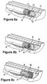
- Figs. 8a through 8c there are illustrated three different methods of terminating the optical fibers 38, which form the fiber bundles 36 within the stainless steel guide tubes 42 located in view ports 34.
- the optical fibers 38 terminate at a location spaced from the distal end of the guide tube 42.
- a shaped lens 90 supported within a frame 92 is joined to the distal end of the guide tube 42.
- the lens 90 is formed from a material such a sapphire and is used to focus or otherwise modify the field of view of the optical fibers 38. It is envisioned that the exposed surface of the lens 90 would have a protective coating.
- the lens can have a vapor deposited layer comprising a mixture of platinum and aluminum oxide which acts as a catalyst to promote oxidation of soot to a gaseous form and thereby reduce contamination of the lens, as disclosed in U.S. Patent No. 4,521,088 to Masom, the disclosure of which is incorporated herein by reference in its entirety.
- the optical fibers 38 terminate at a location spaced from the distal end of the guide tube 42, and a window 94 supported within a frame 96 is joined to the distal end of the guide tube 42.
- the window 94 may be formed from sapphire or a similar transparent material and would function to seal the end of the guide tube from contamination and combustion by-products, which could degrade the optical fibers. It is envisioned that the window 94 could also be frosted or otherwise treated and used as a diffuser to widen the viewing area of the optical fiber bundle.
- each optical fiber 38 in fiber bundle 36 is splayed or otherwise spread outwardly so that each individual fiber end 38a is oriented or directed in a different direction relative to the axis of the bundle. This enables the optical fibers to gather light from a broader or greater area.
- Protective coatings could be used to coat the ends of the fibers.
- the fiber optic instrumented fuel injector of the subject invention may be used for a multiplicity of purposes including, for example, engine control through detection of combustion instability; fuel to air ratio stability by analyzing spectral relationships; obtaining turbine inlet temperature correlated to flame temperature; detection of fuel impurities based on spectral anomalies; aircraft augmenter flame detection; obtaining turbine inlet vane temperature by way of a pyrometer; and advanced warning or prediction of lean blowout conditions.
Abstract
Description
Claims (38)
- A fuel injector for a gas turbine combustor, comprising:a) a feed arm including means for mounting the injector within the combustor;b) a fuel nozzle depending from the feed arm for injecting fuel into the combustor for combustion; andc) optical sensing means embedded in the fuel nozzle for observing combustion conditions within the combustor.
- A fuel injector as recited in Claim 1, wherein the fuel nozzle has a central axis and includes an outer swirler having a leading edge, and wherein a plurality of circumferentially spaced apart viewing ports are formed in the leading edge of the outer swirler.
- A fuel injector as recited in Claim 2, wherein the leading edge of the outer swirler includes three viewing ports spaced equidistant from one another.
- A fuel injector as recited in Claim 2, wherein the optical sensing means includes a plurality of optical fiber bundles, and wherein an optical fiber bundle is accommodated within each viewing port.
- A fuel injector as recited in Claim 4, wherein each optical fiber bundle includes a plurality of optical fibers that extend generally parallel to the central axis of the nozzle.
- A fuel injector as recited in Claim 4, wherein the optical fibers are treated to withstand operating temperatures within the combustor.
- A fuel injector as recited in Claim 6, wherein the optical fibers are provided with a metal coating.
- A fuel injector as recited in Claim 4, wherein each optical fiber bundle is disposed within a temperature resistant guide tube.
- A fuel injector as recited in Claim 8, wherein each guide tube is formed from stainless steel.
- A fuel injector as recited in Claim 8, wherein each guide tube is cemented within a corresponding viewing port in a manner that accommodates thermal expansion and contraction.
- A fuel injector as recited in Claim 4, wherein each optical fiber bundle has a field of view of between about 14° and 30° relative to axis of fiber.
- A fuel injector as recited in Claim 8, wherein a lens is provided at the distal end of the guide tube for modifying the field of view of the optical fiber bundle disposed therein.
- A fuel injector as recited in Claim 8, wherein a window is provided at the distal end of the guide tube to seal the interior of the guide tube and protect the optical fiber bundle disposed therein.
- A fuel injector as recited in Claim 8, wherein distal end portions of the optical fibers of an optical fiber bundle are splayed radially outwardly to enhance the field of view of the optical fiber bundle.
- A fuel injector as recited in Claim 4, wherein the optical sensing means further includes at least one optical fiber mounted along the axis of the nozzle.
- A fuel injector as recited in Claim 1, wherein the optical sensing means communicates with means for processing optical signals.
- A fuel injector as recited in Claim 16, wherein the means for processing optical signals includes means for detecting combustion instabilities based upon conditions observed by the optical sensing means within the fuel nozzle.
- A fuel injector as recited in Claim 17, wherein the means for detecting combustion instabilities communicates with means for modulating the rate of fuel flow to the fuel injector to reduce detected combustion instabilities.
- A fuel injector as recited in Claim 4, wherein the optical fibers are UV enhanced fibers.
- A fuel injector as recited in Claim 4, wherein the optical fibers are IR enhanced fibers.
- A fuel injector for a gas turbine combustor, comprising:a) a feed arm including means for attaching the fuel injector to the combustor; andb) a fuel nozzle having an upstream end associated with the feed arm and a downstream end for issuing fuel into the combustor, the fuel nozzle including an optical sensor array for viewing conditions within the combustor downstream from said nozzle.
- A fuel injector as recited in Claim 21, wherein the fuel nozzle has a central axis and includes an outer swirler having a leading edge, and wherein a plurality of circumferentially spaced apart viewing ports are formed in the leading edge of the outer swirler.
- A fuel injector as recited in Claim 22, wherein the optical sensor array includes a plurality of optical fiber bundles, and wherein an optical fiber bundle is accommodated within each viewing port.
- A fuel injector as recited in Claim 23, wherein the optical fibers in each optical fiber bundle are treated to withstand operating temperatures within the combustor.
- A fuel injector as recited in Claim 23, wherein each optical fiber bundle is disposed within a temperature resistant guide tube.
- A fuel injector as recited in Claim 23, wherein the optical sensor array further includes at least one optical fiber are mounted along the axis of the nozzle.
- A fuel injector as recited in Claim 23, wherein the optical fibers are UV enhanced fibers.
- A fuel injector as recited in Claim 23, wherein the optical fibers are IR enhanced fibers.
- A system for stabilizing combustion in a gas turbine engine, the system comprising:a) optical sensing means embedded within a fuel injector for observing conditions within a combustion chamber of a gas turbine engine;b) means for detecting combustion instabilities based upon conditions observed by the optical sensing means; andc) means for modulating a fuel flow rate to reduce detected combustion instabilities.
- A system as recited in Claim 29, wherein the means for detecting combustion instabilities includes means for detecting changes in flame intensity at levels indicative of flame instability.
- A system as recited in Claim 29, wherein the means for detecting combustion instabilities includes means for detecting spectral radiation indicative of fuel contaminants effecting fuel heat values.
- A system as recited in Claim 29, wherein the means for detecting combustion instabilities includes means for detecting spectral radiation indicative of chemical emissions effecting flame temperature, NOx, CO and fuel/air ratio.
- A system as recited in Claim 29, wherein the means for modulating fuel flow to reduce detected combustion instabilities includes a fuel control system operatively associated with a fuel pump.
- A method of stabilizing combustion in gas turbine engine, comprising the steps of:a) observing a combustor flame from a location upstream from said flame to detect spectral characteristics indicative of a condition affecting combustion stability; andb) tuning the engine to stabilize combustion based upon an indicated condition effecting combustion stability.
- A system as recited in Claim 34, wherein the step of observing a combustor flame includes the step of detecting changes in spectral intensity indicative of flame stability.
- A system as recited in Claim 34, wherein the step of observing a combustor flame includes the step of detecting changes in spectral peaks indicative of stoichiometric instability.
- A method as recited in Claim 34, wherein the step of tuning the engine includes adjusting the fuel to air ratio for combustion.
- A method as recited in Claim 34, wherein the step of tuning the engine includes adjusting the fuel flow rate to the combustor.
Priority Applications (1)
| Application Number | Priority Date | Filing Date | Title |
|---|---|---|---|
| EP12001631.6A EP2508801B1 (en) | 2004-05-07 | 2005-03-30 | System for observing combustion conditions in a gas turbine |
Applications Claiming Priority (2)
| Application Number | Priority Date | Filing Date | Title |
|---|---|---|---|
| US841765 | 1986-03-20 | ||
| US10/841,765 US7334413B2 (en) | 2004-05-07 | 2004-05-07 | Apparatus, system and method for observing combustion conditions in a gas turbine engine |
Related Child Applications (2)
| Application Number | Title | Priority Date | Filing Date |
|---|---|---|---|
| EP12001631.6A Division EP2508801B1 (en) | 2004-05-07 | 2005-03-30 | System for observing combustion conditions in a gas turbine |
| EP12001631.6A Division-Into EP2508801B1 (en) | 2004-05-07 | 2005-03-30 | System for observing combustion conditions in a gas turbine |
Publications (2)
| Publication Number | Publication Date |
|---|---|
| EP1593910A1 true EP1593910A1 (en) | 2005-11-09 |
| EP1593910B1 EP1593910B1 (en) | 2016-05-04 |
Family
ID=34934589
Family Applications (2)
| Application Number | Title | Priority Date | Filing Date |
|---|---|---|---|
| EP05006923.6A Expired - Fee Related EP1593910B1 (en) | 2004-05-07 | 2005-03-30 | Apparatus and method for observing combustion conditions in a gas turbine engine |
| EP12001631.6A Expired - Fee Related EP2508801B1 (en) | 2004-05-07 | 2005-03-30 | System for observing combustion conditions in a gas turbine |
Family Applications After (1)
| Application Number | Title | Priority Date | Filing Date |
|---|---|---|---|
| EP12001631.6A Expired - Fee Related EP2508801B1 (en) | 2004-05-07 | 2005-03-30 | System for observing combustion conditions in a gas turbine |
Country Status (2)
| Country | Link |
|---|---|
| US (3) | US7334413B2 (en) |
| EP (2) | EP1593910B1 (en) |
Cited By (7)
| Publication number | Priority date | Publication date | Assignee | Title |
|---|---|---|---|---|
| DE102008022117A1 (en) * | 2007-06-15 | 2008-12-18 | Alstom Technology Ltd. | Method for determining thermoacoustic transfer function of burner of combustion system, particularly combustion chamber of gas turbine, involves forming transfer function by two partial transfer functions |
| GB2451144A (en) * | 2007-07-26 | 2009-01-21 | Gen Electric | Method and apparatus for actively controlling fuel flow to a mixer assembly of a gas turbine engine combustor |
| FR2928697A1 (en) * | 2008-03-12 | 2009-09-18 | Delavan Inc | ACTIVE THERMAL DIFFERENCE COEFFICIENT REGULATION FOR GAS TURBINE ENGINE |
| FR2969291A1 (en) * | 2010-12-17 | 2012-06-22 | Gen Electric | SYSTEM AND METHOD FOR REAL-TIME MEASUREMENT OF THE WEALTH OF A MIXTURE OF GAS AND FUEL |
| US8607575B2 (en) | 2006-05-23 | 2013-12-17 | General Electric Company | Method and apparatus for actively controlling fuel flow to a mixer assembly of a gas turbine engine combustor |
| ITUA20162044A1 (en) * | 2016-03-25 | 2017-09-25 | A S En Ansaldo Sviluppo Energia S R L | GAS TURBINE PLANT WITH DETECTION OF THERMO ACOUSTIC INSTABILITIES AND METHOD OF CONTROL OF A GAS TURBINE SYSTEM |
| GB2572853A (en) * | 2018-03-26 | 2019-10-16 | Rolls Royce Plc | A full injector, a combustion chamber comprising a fuel injector and a method of detecting coking in a combustion chamber fuel injector |
Families Citing this family (69)
| Publication number | Priority date | Publication date | Assignee | Title |
|---|---|---|---|---|
| DE10308384A1 (en) * | 2003-02-27 | 2004-09-09 | Alstom Technology Ltd | Operating procedure for a gas turbine |
| DE10333671A1 (en) * | 2003-07-24 | 2005-08-04 | Alstom Technology Ltd | Method for reducing the NOx emissions of a burner assembly comprising several burners and burner arrangement for carrying out the method |
| US7334413B2 (en) | 2004-05-07 | 2008-02-26 | Rosemount Aerospace Inc. | Apparatus, system and method for observing combustion conditions in a gas turbine engine |
| US7775052B2 (en) | 2004-05-07 | 2010-08-17 | Delavan Inc | Active combustion control system for gas turbine engines |
| US7966834B2 (en) * | 2004-05-07 | 2011-06-28 | Rosemount Aerospace Inc. | Apparatus for observing combustion conditions in a gas turbine engine |
| US7377114B1 (en) * | 2004-06-02 | 2008-05-27 | Kevin P Pearce | Turbine engine pulsed fuel injection utilizing stagger injector operation |
| US8162287B2 (en) * | 2005-12-29 | 2012-04-24 | Delavan Inc | Valve assembly for modulating fuel flow to a gas turbine engine |
| US7665305B2 (en) * | 2005-12-29 | 2010-02-23 | Delavan Inc | Valve assembly for modulating fuel flow to a gas turbine engine |
| JP4105742B2 (en) * | 2006-02-01 | 2008-06-25 | 国立大学法人 岡山大学 | Fuel quality judgment device and fuel quality judgment method |
| CA2541092A1 (en) * | 2006-03-28 | 2007-09-28 | Murray Thomson | Infrared light sensors for diagnosis and control of industrial furnace gases |
| DE102006015230A1 (en) * | 2006-03-30 | 2007-10-18 | Alstom Technology Ltd. | combustion chamber |
| US20070251663A1 (en) * | 2006-04-28 | 2007-11-01 | William Sheldon | Active temperature feedback control of continuous casting |
| EP2124998B8 (en) * | 2006-12-27 | 2015-05-06 | The Johns Hopkins University | Methods for detecting inflammation and auto-immune diseases |
| EP2097675A1 (en) * | 2007-01-02 | 2009-09-09 | Siemens Aktiengesellschaft | Pressure measurement device, burner and fuel supply for a gas turbine |
| US7549797B2 (en) * | 2007-02-21 | 2009-06-23 | Rosemount Aerospace Inc. | Temperature measurement system |
| US9568197B2 (en) * | 2007-07-09 | 2017-02-14 | United Technologies Corporation | Integrated fuel nozzle with feedback control for a gas turbine engine |
| US20090077945A1 (en) * | 2007-08-24 | 2009-03-26 | Delavan Inc | Variable amplitude double binary valve system for active fuel control |
| US8239114B2 (en) * | 2008-02-12 | 2012-08-07 | Delavan Inc | Methods and systems for modulating fuel flow for gas turbine engines |
| US8371102B1 (en) * | 2008-02-26 | 2013-02-12 | Spectral Sciences, Inc. | Combustor control based on fuel modulation and passive optical sensors |
| US20090318274A1 (en) * | 2008-06-18 | 2009-12-24 | Christopher Welsh | Balance trainer |
| US9759424B2 (en) * | 2008-10-29 | 2017-09-12 | United Technologies Corporation | Systems and methods involving reduced thermo-acoustic coupling of gas turbine engine augmentors |
| US9194273B2 (en) | 2008-10-31 | 2015-11-24 | Cummins Inc. | Apparatus, system, and method for aftertreatment control and diagnostics |
| US8648322B2 (en) * | 2008-10-31 | 2014-02-11 | Cummins Inc. | Optical sensing in an adverse environment |
| US7987712B2 (en) * | 2008-12-10 | 2011-08-02 | Rosemount Aerospace Inc. | High temperature seal assembly for optical sensor |
| US8926317B2 (en) | 2008-12-15 | 2015-01-06 | Exxonmobil Research And Engineering Company | System and method for controlling fired heater operations |
| US8752362B2 (en) * | 2009-01-15 | 2014-06-17 | General Electric Company | Optical flame holding and flashback detection |
| JP5220642B2 (en) * | 2009-02-05 | 2013-06-26 | サーパス工業株式会社 | Differential pressure flow meter and flow controller |
| US8432440B2 (en) * | 2009-02-27 | 2013-04-30 | General Electric Company | System and method for adjusting engine parameters based on flame visualization |
| US9671797B2 (en) | 2009-05-08 | 2017-06-06 | Gas Turbine Efficiency Sweden Ab | Optimization of gas turbine combustion systems low load performance on simple cycle and heat recovery steam generator applications |
| US9267443B2 (en) | 2009-05-08 | 2016-02-23 | Gas Turbine Efficiency Sweden Ab | Automated tuning of gas turbine combustion systems |
| US9354618B2 (en) | 2009-05-08 | 2016-05-31 | Gas Turbine Efficiency Sweden Ab | Automated tuning of multiple fuel gas turbine combustion systems |
| US8437941B2 (en) * | 2009-05-08 | 2013-05-07 | Gas Turbine Efficiency Sweden Ab | Automated tuning of gas turbine combustion systems |
| US9353947B2 (en) * | 2009-06-11 | 2016-05-31 | General Electric Company | Combustor flashback/flame holding detection via temperature sensing |
| US8456634B2 (en) * | 2009-06-15 | 2013-06-04 | General Electric Company | Optical interrogation sensors for combustion control |
| US20110008737A1 (en) * | 2009-06-15 | 2011-01-13 | General Electric Company | Optical sensors for combustion control |
| KR101081080B1 (en) | 2009-06-30 | 2011-11-07 | 한국전력공사 | Auto combustion tuning device for gas turbine and method thereof |
| US20110072826A1 (en) * | 2009-09-25 | 2011-03-31 | General Electric Company | Can to can modal decoupling using can-level fuel splits |
| US8434310B2 (en) * | 2009-12-03 | 2013-05-07 | Delavan Inc | Trim valves for modulating fluid flow |
| US8505303B2 (en) * | 2009-12-11 | 2013-08-13 | General Electric Company | Impurity detection in combustor systems |
| US8915089B2 (en) * | 2010-01-25 | 2014-12-23 | General Electric Company | System and method for detecting and controlling flashback and flame holding within a combustor |
| US20110232296A1 (en) * | 2010-03-24 | 2011-09-29 | General Electric Company | Optical fuel nozzle flashback detector |
| US20110239621A1 (en) * | 2010-03-30 | 2011-10-06 | Meneely Clinton T | Fiber optic microphones for active combustion control |
| US8218147B2 (en) | 2010-06-18 | 2012-07-10 | Cummins Inc. | Apparatus, system, and method for detecting engine fluid constituents |
| US8650883B2 (en) * | 2010-08-11 | 2014-02-18 | General Electric Company | System and method for operating a gas turbine |
| US10704958B2 (en) * | 2010-10-21 | 2020-07-07 | Siemens Energy, Inc. | Method for monitoring a high-temperature region of interest in a turbine engine |
| US10132688B2 (en) * | 2010-12-17 | 2018-11-20 | General Electric Company | System and method for detecting spall within a turbine engine |
| US8899049B2 (en) * | 2011-01-07 | 2014-12-02 | General Electric Company | System and method for controlling combustor operating conditions based on flame detection |
| US20130025253A1 (en) * | 2011-07-27 | 2013-01-31 | Rajani Kumar Akula | Reduction of co and o2 emissions in oxyfuel hydrocarbon combustion systems using oh radical formation with hydrogen fuel staging and diluent addition |
| US20130040254A1 (en) * | 2011-08-08 | 2013-02-14 | General Electric Company | System and method for monitoring a combustor |
| US8387399B1 (en) * | 2011-09-12 | 2013-03-05 | General Electric Company | System and method for controlling a combustor assembly |
| US20130247576A1 (en) | 2012-03-23 | 2013-09-26 | Delavan Inc | Apparatus, system and method for observing combustor flames in a gas turbine engine |
| US9335046B2 (en) * | 2012-05-30 | 2016-05-10 | General Electric Company | Flame detection in a region upstream from fuel nozzle |
| US10392959B2 (en) * | 2012-06-05 | 2019-08-27 | General Electric Company | High temperature flame sensor |
| US9435690B2 (en) * | 2012-06-05 | 2016-09-06 | General Electric Company | Ultra-violet flame detector with high temperature remote sensing element |
| US20140096526A1 (en) * | 2012-10-08 | 2014-04-10 | General Electric Company | System for operating a combustor of a gas turbine |
| US9765702B2 (en) * | 2013-03-15 | 2017-09-19 | Ansaldo Energia Ip Uk Limited | Ensuring non-excessive variation of gradients in auto-tuning a gas turbine engine |
| US9482596B2 (en) * | 2013-06-24 | 2016-11-01 | General Electric Company | Optical monitoring system for a gas turbine engine |
| US20150075170A1 (en) * | 2013-09-17 | 2015-03-19 | General Electric Company | Method and system for augmenting the detection reliability of secondary flame detectors in a gas turbine |
| JP6366259B2 (en) * | 2013-11-18 | 2018-08-01 | 三菱日立パワーシステムズ株式会社 | Control device and control method for two-shaft gas turbine |
| US9423317B2 (en) * | 2013-12-31 | 2016-08-23 | Inventus Holdings, Llc | Combustion chamber measurement system |
| US9773584B2 (en) | 2014-11-24 | 2017-09-26 | General Electric Company | Triaxial mineral insulated cable in flame sensing applications |
| US9976745B2 (en) * | 2015-08-07 | 2018-05-22 | Delavan Inc. | Image conduit for fuel nozzle assemblies |
| US10072843B2 (en) * | 2015-10-21 | 2018-09-11 | Honeywell International Inc. | Combustion resonance suppression |
| US10774753B2 (en) | 2016-10-21 | 2020-09-15 | General Electric Company | Indirect monitoring of aircraft combustor dynamics |
| US11092083B2 (en) | 2017-02-10 | 2021-08-17 | General Electric Company | Pressure sensor assembly for a turbine engine |
| US11619384B2 (en) * | 2017-04-24 | 2023-04-04 | General Electric Technology Gmbh | System and method for operating a combustion chamber |
| CN108613176A (en) * | 2018-05-03 | 2018-10-02 | 蓬莱市海正机械配件有限公司 | Photoelectricity merges intelligent burner |
| US10935431B2 (en) | 2018-09-21 | 2021-03-02 | Raytheon Technologies Corporation | Sensor arrangement for measuring gas turbine combustor temperatures |
| US20230280033A1 (en) * | 2022-03-07 | 2023-09-07 | Baker Hughes Holdings Llc | Combustion Quality Spectrum |
Citations (8)
| Publication number | Priority date | Publication date | Assignee | Title |
|---|---|---|---|---|
| US5257496A (en) * | 1992-05-05 | 1993-11-02 | General Electric Company | Combustion control for producing low NOx emissions through use of flame spectroscopy |
| EP0816760A1 (en) * | 1996-06-24 | 1998-01-07 | General Electric Company | Fiber optic flashback detection |
| US5828797A (en) * | 1996-06-19 | 1998-10-27 | Meggitt Avionics, Inc. | Fiber optic linked flame sensor |
| US5857320A (en) * | 1996-11-12 | 1999-01-12 | Westinghouse Electric Corporation | Combustor with flashback arresting system |
| WO1999030006A2 (en) * | 1997-12-05 | 1999-06-17 | Meggitt Avionics, Inc. | Method and apparatus for characterizing a combustion flame |
| US5961314A (en) * | 1997-05-06 | 1999-10-05 | Rosemount Aerospace Inc. | Apparatus for detecting flame conditions in combustion systems |
| US6142665A (en) * | 1996-07-18 | 2000-11-07 | Abb Alstom Power Ltd | Temperature sensor arrangement in combination with a gas turbine combustion chamber |
| US20020125336A1 (en) * | 2001-03-07 | 2002-09-12 | Bretz David H. | Air assist fuel nozzle |
Family Cites Families (18)
| Publication number | Priority date | Publication date | Assignee | Title |
|---|---|---|---|---|
| US2975785A (en) * | 1957-09-26 | 1961-03-21 | Bausch & Lomb | Optical viewing instrument |
| US3689773A (en) * | 1971-02-01 | 1972-09-05 | Bailey Miters & Controls Ltd | Flame monitor system and method using multiple radiation sensors |
| DE3321028A1 (en) * | 1982-06-17 | 1983-12-22 | Smiths Industries Public Ltd. Co., London | OPTICAL COMPONENT |
| JPS61124828A (en) | 1984-11-22 | 1986-06-12 | Babcock Hitachi Kk | Flame monitor apparatus |
| US4709155A (en) * | 1984-11-22 | 1987-11-24 | Babcock-Hitachi Kabushiki Kaisha | Flame detector for use with a burner |
| FR2628667A1 (en) * | 1988-03-21 | 1989-09-22 | Donze Michel | GAS TORCH HAVING A VISUAL OBSERVATION DEVICE |
| US5499497A (en) | 1993-08-06 | 1996-03-19 | Simmonds Precision Engine Systems | Temperature detector and control for an igniter |
| US5450727A (en) * | 1994-05-27 | 1995-09-19 | Hughes Aircraft Company | Thermoelectric cooler controller, thermal reference source and detector |
| US5719791A (en) | 1995-03-17 | 1998-02-17 | Georgia Tech Research Corporation | Methods, apparatus and systems for real time identification and control of modes of oscillation |
| US5608515A (en) * | 1995-04-20 | 1997-03-04 | General Electric Company | Double window for protecting optical sensors from hazardous environments |
| JP3453973B2 (en) * | 1995-12-27 | 2003-10-06 | 株式会社豊田中央研究所 | Control method of premixed combustion device |
| US6599028B1 (en) * | 1997-06-17 | 2003-07-29 | General Electric Company | Fiber optic sensors for gas turbine control |
| US6472669B1 (en) * | 1999-02-02 | 2002-10-29 | Abb Research Ltd. | Silicon carbide photodiode based flame scanner |
| AT5153U1 (en) * | 2001-03-22 | 2002-03-25 | Avl List Gmbh | OPTICAL SENSOR FOR DETECTING COMBUSTION |
| US6640548B2 (en) * | 2001-09-26 | 2003-11-04 | Siemens Westinghouse Power Corporation | Apparatus and method for combusting low quality fuel |
| CA2466752C (en) * | 2001-11-13 | 2011-05-24 | John C. Barton | Touchless automatic fiber optic beverage/ice dispenser |
| US7484369B2 (en) | 2004-05-07 | 2009-02-03 | Rosemount Aerospace Inc. | Apparatus for observing combustion conditions in a gas turbine engine |
| US7334413B2 (en) | 2004-05-07 | 2008-02-26 | Rosemount Aerospace Inc. | Apparatus, system and method for observing combustion conditions in a gas turbine engine |
-
2004
- 2004-05-07 US US10/841,765 patent/US7334413B2/en active Active
-
2005
- 2005-03-30 EP EP05006923.6A patent/EP1593910B1/en not_active Expired - Fee Related
- 2005-03-30 EP EP12001631.6A patent/EP2508801B1/en not_active Expired - Fee Related
-
2007
- 2007-11-29 US US11/998,301 patent/US8297060B2/en active Active
-
2009
- 2009-02-02 US US12/322,421 patent/US8136360B2/en not_active Expired - Fee Related
Patent Citations (8)
| Publication number | Priority date | Publication date | Assignee | Title |
|---|---|---|---|---|
| US5257496A (en) * | 1992-05-05 | 1993-11-02 | General Electric Company | Combustion control for producing low NOx emissions through use of flame spectroscopy |
| US5828797A (en) * | 1996-06-19 | 1998-10-27 | Meggitt Avionics, Inc. | Fiber optic linked flame sensor |
| EP0816760A1 (en) * | 1996-06-24 | 1998-01-07 | General Electric Company | Fiber optic flashback detection |
| US6142665A (en) * | 1996-07-18 | 2000-11-07 | Abb Alstom Power Ltd | Temperature sensor arrangement in combination with a gas turbine combustion chamber |
| US5857320A (en) * | 1996-11-12 | 1999-01-12 | Westinghouse Electric Corporation | Combustor with flashback arresting system |
| US5961314A (en) * | 1997-05-06 | 1999-10-05 | Rosemount Aerospace Inc. | Apparatus for detecting flame conditions in combustion systems |
| WO1999030006A2 (en) * | 1997-12-05 | 1999-06-17 | Meggitt Avionics, Inc. | Method and apparatus for characterizing a combustion flame |
| US20020125336A1 (en) * | 2001-03-07 | 2002-09-12 | Bretz David H. | Air assist fuel nozzle |
Cited By (16)
| Publication number | Priority date | Publication date | Assignee | Title |
|---|---|---|---|---|
| US8607575B2 (en) | 2006-05-23 | 2013-12-17 | General Electric Company | Method and apparatus for actively controlling fuel flow to a mixer assembly of a gas turbine engine combustor |
| DE102008022117B4 (en) * | 2007-06-15 | 2019-04-04 | Ansaldo Energia Switzerland AG | Method and test bench for determining a transfer function |
| DE102008022117A1 (en) * | 2007-06-15 | 2008-12-18 | Alstom Technology Ltd. | Method for determining thermoacoustic transfer function of burner of combustion system, particularly combustion chamber of gas turbine, involves forming transfer function by two partial transfer functions |
| GB2451144A (en) * | 2007-07-26 | 2009-01-21 | Gen Electric | Method and apparatus for actively controlling fuel flow to a mixer assembly of a gas turbine engine combustor |
| GB2451144B (en) * | 2007-07-26 | 2011-11-16 | Gen Electric | Method and apparatus for actively controlling fuel flow to a mixer assembly of a gas turbine engine combuster |
| FR2928697A1 (en) * | 2008-03-12 | 2009-09-18 | Delavan Inc | ACTIVE THERMAL DIFFERENCE COEFFICIENT REGULATION FOR GAS TURBINE ENGINE |
| FR2969291A1 (en) * | 2010-12-17 | 2012-06-22 | Gen Electric | SYSTEM AND METHOD FOR REAL-TIME MEASUREMENT OF THE WEALTH OF A MIXTURE OF GAS AND FUEL |
| CN102608067A (en) * | 2010-12-17 | 2012-07-25 | 通用电气公司 | System and method for real-time measurement of equivalence ratio of gas fuel mixture |
| CN102608067B (en) * | 2010-12-17 | 2016-08-03 | 通用电气公司 | System and method for the equivalent proportion of measurement gas-fuel mixture in real time |
| ITUA20162044A1 (en) * | 2016-03-25 | 2017-09-25 | A S En Ansaldo Sviluppo Energia S R L | GAS TURBINE PLANT WITH DETECTION OF THERMO ACOUSTIC INSTABILITIES AND METHOD OF CONTROL OF A GAS TURBINE SYSTEM |
| CN107228017A (en) * | 2016-03-25 | 2017-10-03 | 安萨尔多能源公司 | It is provided with the method for the gas-turbine plant and control gas-turbine plant of the unstable detection of thermoacoustic |
| EP3222915A1 (en) * | 2016-03-25 | 2017-09-27 | Ansaldo Energia S.p.A. | A gas-turbine plant provided with thermoacoustic instability detection and method of controlling a gas-turbine plant |
| CN107228017B (en) * | 2016-03-25 | 2021-11-02 | 安萨尔多能源公司 | Gas turbine plant provided with thermoacoustic instability detection and method for controlling the same |
| GB2572853A (en) * | 2018-03-26 | 2019-10-16 | Rolls Royce Plc | A full injector, a combustion chamber comprising a fuel injector and a method of detecting coking in a combustion chamber fuel injector |
| GB2572853B (en) * | 2018-03-26 | 2020-08-05 | Rolls Royce Plc | A fuel injector, a combustion chamber comprising a fuel injector and a method of detecting coking in a combustion chamber fuel injector |
| US10890116B2 (en) | 2018-03-26 | 2021-01-12 | Rolls-Royce Plc | Fuel injector, a combustion chamber comprising a fuel injector and a method of detecting coking in a combustion chamber fuel injector |
Also Published As
| Publication number | Publication date |
|---|---|
| EP2508801B1 (en) | 2017-06-14 |
| US20050247066A1 (en) | 2005-11-10 |
| US8136360B2 (en) | 2012-03-20 |
| US20080083228A1 (en) | 2008-04-10 |
| EP1593910B1 (en) | 2016-05-04 |
| EP2508801A2 (en) | 2012-10-10 |
| US8297060B2 (en) | 2012-10-30 |
| US20090141349A1 (en) | 2009-06-04 |
| US7334413B2 (en) | 2008-02-26 |
| EP2508801A3 (en) | 2012-11-07 |
Similar Documents
| Publication | Publication Date | Title |
|---|---|---|
| EP1593910B1 (en) | Apparatus and method for observing combustion conditions in a gas turbine engine | |
| US7484369B2 (en) | Apparatus for observing combustion conditions in a gas turbine engine | |
| US7966834B2 (en) | Apparatus for observing combustion conditions in a gas turbine engine | |
| EP2642205B1 (en) | Apparatus for observing combustor flames in a gas turbine engine | |
| JP4112043B2 (en) | Temperature measuring device | |
| Hardalupas et al. | Spatial resolution of a chemiluminescence sensor for local heat-release rate and equivalence ratio measurements in a model gas turbine combustor | |
| US6071114A (en) | Method and apparatus for characterizing a combustion flame | |
| US20110239621A1 (en) | Fiber optic microphones for active combustion control | |
| US9335216B2 (en) | System and method for on-line optical monitoring and control of a gas turbine engine | |
| US20120174590A1 (en) | System and method for controlling combustor operating conditions based on flame detection | |
| US20070234730A1 (en) | Method and apparatus for monitoring combustion instability and other performance deviations in turbine engines and like combustion systems | |
| US8371102B1 (en) | Combustor control based on fuel modulation and passive optical sensors | |
| Brouwer et al. | Active control for gas turbine combustors | |
| JP6018378B2 (en) | Optical combustor probe system | |
| EP3222915B1 (en) | A gas-turbine plant provided with thermoacoustic instability detection and method of controlling a gas-turbine plant | |
| EP3222918B1 (en) | Gas-turbine burner assembly with optical probe | |
| Woodruff | Optical diagnostics in gas turbine combustors | |
| Jenkins et al. | Development of a non-intrusive temperature sensor in a model gas turbine combustor | |
| Markham et al. | Turbine engine augmentor screech and rumble sensor |
Legal Events
| Date | Code | Title | Description |
|---|---|---|---|
| PUAI | Public reference made under article 153(3) epc to a published international application that has entered the european phase |
Free format text: ORIGINAL CODE: 0009012 |
|
| AK | Designated contracting states |
Kind code of ref document: A1 Designated state(s): AT BE BG CH CY CZ DE DK EE ES FI FR GB GR HU IE IS IT LI LT LU MC NL PL PT RO SE SI SK TR |
|
| AX | Request for extension of the european patent |
Extension state: AL BA HR LV MK YU |
|
| 17P | Request for examination filed |
Effective date: 20060215 |
|
| AKX | Designation fees paid |
Designated state(s): DE FR GB SE |
|
| 17Q | First examination report despatched |
Effective date: 20111201 |
|
| GRAP | Despatch of communication of intention to grant a patent |
Free format text: ORIGINAL CODE: EPIDOSNIGR1 |
|
| INTG | Intention to grant announced |
Effective date: 20150610 |
|
| GRAP | Despatch of communication of intention to grant a patent |
Free format text: ORIGINAL CODE: EPIDOSNIGR1 |
|
| INTG | Intention to grant announced |
Effective date: 20151113 |
|
| GRAS | Grant fee paid |
Free format text: ORIGINAL CODE: EPIDOSNIGR3 |
|
| GRAA | (expected) grant |
Free format text: ORIGINAL CODE: 0009210 |
|
| AK | Designated contracting states |
Kind code of ref document: B1 Designated state(s): DE FR GB SE |
|
| REG | Reference to a national code |
Ref country code: GB Ref legal event code: FG4D |
|
| REG | Reference to a national code |
Ref country code: DE Ref legal event code: R096 Ref document number: 602005049215 Country of ref document: DE |
|
| PG25 | Lapsed in a contracting state [announced via postgrant information from national office to epo] |
Ref country code: SE Free format text: LAPSE BECAUSE OF FAILURE TO SUBMIT A TRANSLATION OF THE DESCRIPTION OR TO PAY THE FEE WITHIN THE PRESCRIBED TIME-LIMIT Effective date: 20160504 |
|
| REG | Reference to a national code |
Ref country code: DE Ref legal event code: R097 Ref document number: 602005049215 Country of ref document: DE |
|
| PLBE | No opposition filed within time limit |
Free format text: ORIGINAL CODE: 0009261 |
|
| STAA | Information on the status of an ep patent application or granted ep patent |
Free format text: STATUS: NO OPPOSITION FILED WITHIN TIME LIMIT |
|
| REG | Reference to a national code |
Ref country code: FR Ref legal event code: PLFP Year of fee payment: 13 |
|
| 26N | No opposition filed |
Effective date: 20170207 |
|
| REG | Reference to a national code |
Ref country code: FR Ref legal event code: PLFP Year of fee payment: 14 |
|
| PGFP | Annual fee paid to national office [announced via postgrant information from national office to epo] |
Ref country code: GB Payment date: 20200221 Year of fee payment: 16 Ref country code: DE Payment date: 20200218 Year of fee payment: 16 |
|
| PGFP | Annual fee paid to national office [announced via postgrant information from national office to epo] |
Ref country code: FR Payment date: 20200220 Year of fee payment: 16 |
|
| REG | Reference to a national code |
Ref country code: DE Ref legal event code: R082 Ref document number: 602005049215 Country of ref document: DE |
|
| REG | Reference to a national code |
Ref country code: DE Ref legal event code: R119 Ref document number: 602005049215 Country of ref document: DE |
|
| GBPC | Gb: european patent ceased through non-payment of renewal fee |
Effective date: 20210330 |
|
| PG25 | Lapsed in a contracting state [announced via postgrant information from national office to epo] |
Ref country code: DE Free format text: LAPSE BECAUSE OF NON-PAYMENT OF DUE FEES Effective date: 20211001 Ref country code: FR Free format text: LAPSE BECAUSE OF NON-PAYMENT OF DUE FEES Effective date: 20210331 Ref country code: GB Free format text: LAPSE BECAUSE OF NON-PAYMENT OF DUE FEES Effective date: 20210330 |