EP1591307A2 - Infant travel system - Google Patents
Infant travel system Download PDFInfo
- Publication number
- EP1591307A2 EP1591307A2 EP05103427A EP05103427A EP1591307A2 EP 1591307 A2 EP1591307 A2 EP 1591307A2 EP 05103427 A EP05103427 A EP 05103427A EP 05103427 A EP05103427 A EP 05103427A EP 1591307 A2 EP1591307 A2 EP 1591307A2
- Authority
- EP
- European Patent Office
- Prior art keywords
- base
- seat
- opposed
- frame
- infant travel
- Prior art date
- Legal status (The legal status is an assumption and is not a legal conclusion. Google has not performed a legal analysis and makes no representation as to the accuracy of the status listed.)
- Granted
Links
- 239000007788 liquid Substances 0.000 claims description 12
- 210000000006 pectoral fin Anatomy 0.000 claims description 6
- 230000000630 rising effect Effects 0.000 claims 1
- 239000003981 vehicle Substances 0.000 description 30
- 230000000712 assembly Effects 0.000 description 16
- 238000000429 assembly Methods 0.000 description 16
- 230000000284 resting effect Effects 0.000 description 7
- 230000036961 partial effect Effects 0.000 description 6
- 210000002832 shoulder Anatomy 0.000 description 6
- 238000000034 method Methods 0.000 description 3
- 230000000694 effects Effects 0.000 description 2
- 238000004519 manufacturing process Methods 0.000 description 2
- 239000000463 material Substances 0.000 description 2
- 238000003825 pressing Methods 0.000 description 2
- 238000003860 storage Methods 0.000 description 2
- 230000004913 activation Effects 0.000 description 1
- 230000003247 decreasing effect Effects 0.000 description 1
- 230000000994 depressogenic effect Effects 0.000 description 1
- 239000012634 fragment Substances 0.000 description 1
- 230000003993 interaction Effects 0.000 description 1
- 230000002452 interceptive effect Effects 0.000 description 1
- 230000000670 limiting effect Effects 0.000 description 1
- 230000013011 mating Effects 0.000 description 1
- 238000005259 measurement Methods 0.000 description 1
- 238000012986 modification Methods 0.000 description 1
- 230000004048 modification Effects 0.000 description 1
Images


Classifications
-
- B—PERFORMING OPERATIONS; TRANSPORTING
- B60—VEHICLES IN GENERAL
- B60N—SEATS SPECIALLY ADAPTED FOR VEHICLES; VEHICLE PASSENGER ACCOMMODATION NOT OTHERWISE PROVIDED FOR
- B60N2/00—Seats specially adapted for vehicles; Arrangement or mounting of seats in vehicles
- B60N2/24—Seats specially adapted for vehicles; Arrangement or mounting of seats in vehicles for particular purposes or particular vehicles
- B60N2/26—Seats specially adapted for vehicles; Arrangement or mounting of seats in vehicles for particular purposes or particular vehicles for children
- B60N2/28—Seats readily mountable on, and dismountable from, existing seats or other parts of the vehicle
- B60N2/2842—Seats readily mountable on, and dismountable from, existing seats or other parts of the vehicle adapted to carry the child, when dismounted from the vehicle
- B60N2/2848—Seats readily mountable on, and dismountable from, existing seats or other parts of the vehicle adapted to carry the child, when dismounted from the vehicle being convertible or adaptable to a preambulator, e.g. a baby-carriage or a push-chair
-
- B—PERFORMING OPERATIONS; TRANSPORTING
- B60—VEHICLES IN GENERAL
- B60N—SEATS SPECIALLY ADAPTED FOR VEHICLES; VEHICLE PASSENGER ACCOMMODATION NOT OTHERWISE PROVIDED FOR
- B60N2/00—Seats specially adapted for vehicles; Arrangement or mounting of seats in vehicles
- B60N2/24—Seats specially adapted for vehicles; Arrangement or mounting of seats in vehicles for particular purposes or particular vehicles
- B60N2/26—Seats specially adapted for vehicles; Arrangement or mounting of seats in vehicles for particular purposes or particular vehicles for children
- B60N2/28—Seats readily mountable on, and dismountable from, existing seats or other parts of the vehicle
- B60N2/2803—Adaptations for seat belts
- B60N2/2806—Adaptations for seat belts for securing the child seat to the vehicle
-
- B—PERFORMING OPERATIONS; TRANSPORTING
- B60—VEHICLES IN GENERAL
- B60N—SEATS SPECIALLY ADAPTED FOR VEHICLES; VEHICLE PASSENGER ACCOMMODATION NOT OTHERWISE PROVIDED FOR
- B60N2/00—Seats specially adapted for vehicles; Arrangement or mounting of seats in vehicles
- B60N2/24—Seats specially adapted for vehicles; Arrangement or mounting of seats in vehicles for particular purposes or particular vehicles
- B60N2/26—Seats specially adapted for vehicles; Arrangement or mounting of seats in vehicles for particular purposes or particular vehicles for children
- B60N2/28—Seats readily mountable on, and dismountable from, existing seats or other parts of the vehicle
- B60N2/2803—Adaptations for seat belts
- B60N2/2812—Adaptations for seat belts for securing the child to the child seat
-
- B—PERFORMING OPERATIONS; TRANSPORTING
- B60—VEHICLES IN GENERAL
- B60N—SEATS SPECIALLY ADAPTED FOR VEHICLES; VEHICLE PASSENGER ACCOMMODATION NOT OTHERWISE PROVIDED FOR
- B60N2/00—Seats specially adapted for vehicles; Arrangement or mounting of seats in vehicles
- B60N2/24—Seats specially adapted for vehicles; Arrangement or mounting of seats in vehicles for particular purposes or particular vehicles
- B60N2/26—Seats specially adapted for vehicles; Arrangement or mounting of seats in vehicles for particular purposes or particular vehicles for children
- B60N2/28—Seats readily mountable on, and dismountable from, existing seats or other parts of the vehicle
- B60N2/2821—Seats readily mountable on, and dismountable from, existing seats or other parts of the vehicle having a seat and a base part
-
- B—PERFORMING OPERATIONS; TRANSPORTING
- B60—VEHICLES IN GENERAL
- B60N—SEATS SPECIALLY ADAPTED FOR VEHICLES; VEHICLE PASSENGER ACCOMMODATION NOT OTHERWISE PROVIDED FOR
- B60N2/00—Seats specially adapted for vehicles; Arrangement or mounting of seats in vehicles
- B60N2/24—Seats specially adapted for vehicles; Arrangement or mounting of seats in vehicles for particular purposes or particular vehicles
- B60N2/26—Seats specially adapted for vehicles; Arrangement or mounting of seats in vehicles for particular purposes or particular vehicles for children
- B60N2/28—Seats readily mountable on, and dismountable from, existing seats or other parts of the vehicle
- B60N2/2842—Seats readily mountable on, and dismountable from, existing seats or other parts of the vehicle adapted to carry the child, when dismounted from the vehicle
- B60N2/2845—Seats readily mountable on, and dismountable from, existing seats or other parts of the vehicle adapted to carry the child, when dismounted from the vehicle having handles
-
- B—PERFORMING OPERATIONS; TRANSPORTING
- B60—VEHICLES IN GENERAL
- B60N—SEATS SPECIALLY ADAPTED FOR VEHICLES; VEHICLE PASSENGER ACCOMMODATION NOT OTHERWISE PROVIDED FOR
- B60N2/00—Seats specially adapted for vehicles; Arrangement or mounting of seats in vehicles
- B60N2/24—Seats specially adapted for vehicles; Arrangement or mounting of seats in vehicles for particular purposes or particular vehicles
- B60N2/26—Seats specially adapted for vehicles; Arrangement or mounting of seats in vehicles for particular purposes or particular vehicles for children
- B60N2/28—Seats readily mountable on, and dismountable from, existing seats or other parts of the vehicle
- B60N2/2857—Seats readily mountable on, and dismountable from, existing seats or other parts of the vehicle characterised by the peculiar orientation of the child
- B60N2/2863—Seats readily mountable on, and dismountable from, existing seats or other parts of the vehicle characterised by the peculiar orientation of the child backward facing
-
- B—PERFORMING OPERATIONS; TRANSPORTING
- B60—VEHICLES IN GENERAL
- B60N—SEATS SPECIALLY ADAPTED FOR VEHICLES; VEHICLE PASSENGER ACCOMMODATION NOT OTHERWISE PROVIDED FOR
- B60N2/00—Seats specially adapted for vehicles; Arrangement or mounting of seats in vehicles
- B60N2/24—Seats specially adapted for vehicles; Arrangement or mounting of seats in vehicles for particular purposes or particular vehicles
- B60N2/26—Seats specially adapted for vehicles; Arrangement or mounting of seats in vehicles for particular purposes or particular vehicles for children
- B60N2/28—Seats readily mountable on, and dismountable from, existing seats or other parts of the vehicle
- B60N2/2875—Seats readily mountable on, and dismountable from, existing seats or other parts of the vehicle inclinable, as a whole or partially
-
- B—PERFORMING OPERATIONS; TRANSPORTING
- B60—VEHICLES IN GENERAL
- B60N—SEATS SPECIALLY ADAPTED FOR VEHICLES; VEHICLE PASSENGER ACCOMMODATION NOT OTHERWISE PROVIDED FOR
- B60N2/00—Seats specially adapted for vehicles; Arrangement or mounting of seats in vehicles
- B60N2/24—Seats specially adapted for vehicles; Arrangement or mounting of seats in vehicles for particular purposes or particular vehicles
- B60N2/26—Seats specially adapted for vehicles; Arrangement or mounting of seats in vehicles for particular purposes or particular vehicles for children
- B60N2/28—Seats readily mountable on, and dismountable from, existing seats or other parts of the vehicle
- B60N2/2887—Fixation to a transversal anchorage bar, e.g. isofix
- B60N2/289—Fixation to a transversal anchorage bar, e.g. isofix coupled to the vehicle frame
-
- B—PERFORMING OPERATIONS; TRANSPORTING
- B60—VEHICLES IN GENERAL
- B60N—SEATS SPECIALLY ADAPTED FOR VEHICLES; VEHICLE PASSENGER ACCOMMODATION NOT OTHERWISE PROVIDED FOR
- B60N2/00—Seats specially adapted for vehicles; Arrangement or mounting of seats in vehicles
- B60N2/24—Seats specially adapted for vehicles; Arrangement or mounting of seats in vehicles for particular purposes or particular vehicles
- B60N2/32—Seats specially adapted for vehicles; Arrangement or mounting of seats in vehicles for particular purposes or particular vehicles convertible for other use
-
- B—PERFORMING OPERATIONS; TRANSPORTING
- B62—LAND VEHICLES FOR TRAVELLING OTHERWISE THAN ON RAILS
- B62B—HAND-PROPELLED VEHICLES, e.g. HAND CARTS OR PERAMBULATORS; SLEDGES
- B62B7/00—Carriages for children; Perambulators, e.g. dolls' perambulators
- B62B7/04—Carriages for children; Perambulators, e.g. dolls' perambulators having more than one wheel axis; Steering devices therefor
- B62B7/14—Carriages for children; Perambulators, e.g. dolls' perambulators having more than one wheel axis; Steering devices therefor with detachable or rotatably-mounted body
- B62B7/142—Means for securing the body to the frame
-
- B—PERFORMING OPERATIONS; TRANSPORTING
- B62—LAND VEHICLES FOR TRAVELLING OTHERWISE THAN ON RAILS
- B62B—HAND-PROPELLED VEHICLES, e.g. HAND CARTS OR PERAMBULATORS; SLEDGES
- B62B9/00—Accessories or details specially adapted for children's carriages or perambulators
- B62B9/10—Perambulator bodies; Equipment therefor
- B62B9/12—Perambulator bodies; Equipment therefor involving parts that are adjustable, attachable or detachable
-
- B—PERFORMING OPERATIONS; TRANSPORTING
- B62—LAND VEHICLES FOR TRAVELLING OTHERWISE THAN ON RAILS
- B62B—HAND-PROPELLED VEHICLES, e.g. HAND CARTS OR PERAMBULATORS; SLEDGES
- B62B7/00—Carriages for children; Perambulators, e.g. dolls' perambulators
- B62B7/04—Carriages for children; Perambulators, e.g. dolls' perambulators having more than one wheel axis; Steering devices therefor
- B62B7/14—Carriages for children; Perambulators, e.g. dolls' perambulators having more than one wheel axis; Steering devices therefor with detachable or rotatably-mounted body
- B62B7/145—Carriages for children; Perambulators, e.g. dolls' perambulators having more than one wheel axis; Steering devices therefor with detachable or rotatably-mounted body the body being a rigid seat, e.g. a shell
Definitions
- the present invention relates gen erally to infant travel systems which include an infant travel seat that can be mounted to a stationary or mobile base. More particularly, the present invention relates to a restra int system for securing a base component of the infant travel system to a vehicle seat, a leveling system for the base, a multi-point locking system to secure an infant travel seat to a complimentary base, and a travel seat carrying handle assembly.
- Infant travel systems comprising an infant travel seat and complimentary base assembly are well-known in the art.
- the engaging mechanism s between the infant travel seat and the base is difficult to operate or does not form a secure fit.
- the location of the engagement between the seat and base in prior art systems is not optimally positioned to account for the various effects of front and rear end collisions. Therefore, there is a need for a more user friendly sys tem for engaging and releasing the infant travel seat to and from the base.
- a leve ling system is typically located on either the base or seat.
- the seat When the indicator is positioned on the seat, the seat is required to be mounted to the base for a user to read the level. If the base needs to be adjusted, the seat typically has to be disenga ged from the base, which can be frustrating for a user.
- the level When the level is located on the base, it is often concealed by the seat or can only be read from one side of the base.
- prior art leveling systems typically in the form of a pendulum with an indicator, can be confusing for a user to read and are not user friendly. Therefore, there is a need for an improved and more user friendly leveling system to be located on the base assembly.
- Adjustable carrying handles for infant travel seats are well known. In many infant travel seats, the position of the carrying handle can break free when minimum for ce is applied. This is because there is typically only a singular locking engagement between the handle and seat or the adjustable locking engagement between the handle and seat is perpendicular to the radial rotation of the handle. Therefore, there is a need for an adjustable handle locking mechanism having an improved engagement between the handle and seat.
- the base includes a frame dimensioned to rest upon a vehicle seat, defines front and rear portions, and a center line.
- An adjustment assembly is coupled to the frame and includes a locking element.
- the adjustment assembly is positioned at a selected one of the front and rear portions of the frame.
- the base further includes a tether having a free end which is releasably secured in the locking element of the adjustment assembly, and at least one securing end ad apted to be secured to an anchor mounted within the vehicle so that movement of the tether through the locking element adjusts the position of the securing end with respect to the frame.
- the restraint system includes an infant travel seat base dimensio ned to rest upon a vehicle seat.
- the base defines front and rear portions, upper and lower plane s, and a center line.
- At least one adjustment assembly is coupled to the base and includes a locking element.
- the adjustment assembly is positioned at a selected one of the front and rear portion s of the base.
- the restraint system further includes at least one tether having a central portion releasably secur ed in the locking element, and two end portions adapted to be secured to an anchor mounted within the vehicle so that movement of the tether through the locking element adjusts the position of the end portions with respect to the base.
- Another aspect of th e present invention is directed toward a base for supporting an infant travel seat including a frame and at least one liquid bubble level positioned within the frame.
- the frame includes a front end, a rear end, two opposed sides, an upper surface that receives an infant travel seat, and a lower surface configured to rest upon a vehicle seat.
- the infant travel seat includes a shell having a seating portion and two opposing side hubs. Each hub has a central axis, and at least one of the hubs ha s a plurality of circumferential projections extending toward the center of the hub and positi oned radial to the central axis.
- the infant travel seat further includes a handle rotatably connected to the frame. The handle includes two arms, each arm having a hub receiving portion. T he hub receiving portion of each arm is adapted to be secured to one of the hubs of the shell.
- the infant travel seat further includes at least one locking member connected to the handle, wherein the locking member has at least one engaging portion releasably engageable with at least one of the plurality of circumferential projections.
- the locking member is biased by a handle actuator disposed on the handle to form a radial engagement with at least one of the circumferential projections.
- the handle actuator is adapted to disengage the radial engagement of the locking member with the at least one circumferential projection by displacing the locking member suf ficiently from the plurality of circumferential projections to allow the locking member to rotate on a radial axis with respect to the central axis and adjust the position of the radial engagement of the locking member with at least one the plurality of circumferential projections.
- the infant travel system includes a base assembly and an infant travel seat.
- the base assembly includes front and rear ends and two opposed sid es that define a generally rectangular cuboid having upper and lower surfaces.
- the lower surface is configured to rest upon a vehicle seat, and the upper surface is configured to receive a complimentary infant travel seat.
- the base assembly further include des opposed securing latches positioned at one end of the base for securing an infant travel seat.
- the infant travel seat includes a shell having a head end, a foot end, and opposing sides defining a seat.
- the seat has an interior and exterior.
- the shel 1 further defines opposed receptacles positioned at the foot end of the seat; the opposed receptacles are configured to receive the opposed securing latches of the base.
- An actuating assembly is located on the interior of the seat to control the engagemen t between the opposed receptacles of the seat and the opposed securing latches of the base.
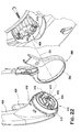
- Fig. 1 is an exploded view of an infant travel seat and base assembly according to the invention.
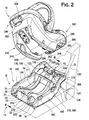
- Fig. 2 is an exploded view of the infant travel seat of Fig. 1 in the direction of arrow A in Fig. 1.
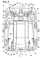
- Fig. 3 is a plan view of the base assembly in the direction of the arrow B in Fig. 2.
- Fig. 4 is an elevational view of the base assembly in the direction of arrow C in Fig. 1.
- Fig. 5 is an elevational view of the base assembly in th e direction of arrow D in Fig. 1.
- Fig. 6 is a cross -sectional view of a vehicle belt lockoff clip of the base assembly along the line 6 -6 of Fig. 5.
- Fig. 7 is an internal view of the base assembly of Fig. 2 with the upper and rear base covers removed.
- Fig. 8 is a cross -sectional view of the base, taken along the line 8 - 8 of Fig. 2 that illustrates repositioning of the foot in phantom.
- Fig. 9 is a partial view of one of the sides of the base assembly showing a bubble level exploded from the base assembly.
- Fig. 10 is a cross -sectional view of the bubble level taken along the line 10-10 in Fig. 9.
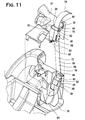
- Fig. 11 is a partial cross -sectional view of the tether assembly of Fig. 8 with the rear base cover and tether adjustment tab exploded from the base assembly.
- Fig. 12 illustrat es the orientation of engagement between the infant travel seat and base assembly of Fig. 1.
- Fig. 13 illustrates the orientation of engagement between the infant travel seat and base assembly of Fig. 1.
- Fig. 14 illustrat es the infant travel seat engaged to the base assembly.
- Fig. 15 is a perspective view of the infant travel s eat shell with an actuator assembly and carrying handle according to the invention.
- Fig. 16 is a perspective view of the infant travel seat actuator assembly.
- Fig. 17 is a partial view of the infant travel seat shell and actuator assembly showing the area of connection between one of the side flippers and a leg end of the actuator assembly when the actuator assembly is in a resting state.
- Fig. 18 is a cross-sectional view of the infant travel seat shell and actuator assembly showing the area of connection between one of the side flippers and a leg end of the actuator assembly when the actuator assembly is in the resting state taken along line 18 -18 of Fig. 17.
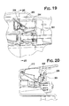
- Fig. 19 is a partial view of the infant travel seat shell and actuator assembly showing the area of connection between one of the side flippers and a leg end of the actuator assembly when the actuator assembly is in an activated state.
- Fig. 20 is a cross -sectional view of the infant travel seat shell and actuator assembly showing the area of connection between one of the side flippers and a leg end of the actuator assembly when the actuator assembly is in the activated state taken along line 20-20 of Fig. 19.
- Fig. 21 is a partial cross-sectional view of an attachment mechanism at the upper rear end of the base assembly shown attached to a corresponding receiving mechanism on the infant travel seat.
- Fig. 22 is an exploded view of a first embodiment of the handle attachment as sembly and canopy ring for a canopy frame.
- Fig. 23 is an interior view of one element of the carrying handle of Fig. 22.
- Fig. 24 is an interior view of a first embodiment of the handle attachment of the infant travel seat carrying handle as assembled to il lustrate activation of the handle actuator.
- Figs. 25, 27, and 28 are cross-sectional views illustrating a first embodiment of the handle attachment assembly and locking member in various secured engagement position s.
- Fig. 26 is a cross -sectional view illus trating a first embodiment of the handle attachment assembly and locking member in a disengaged position.
- Fig. 29 is a perspective view of the handle actuator as shown in Fig. 23 as at E.
- Fig. 30 illustrates the orientation of the locking mechanism taken along line 30-30 of Fig. 29.
- Fig. 31 is a fragmentary side view of a canopy attachment mechanism for the infant travel seat.
- Fig. 32 is a front view of a harness chest clip usable with the infant travel seat shown in an engaged position.
- Fig. 33 is a front view of the harness chest clip of Fig. 32 shown in an opened condition.
- Fig. 34 is a plan view in the direction of the line 34 in Fig. 32 .
- Fig. 35 is an exploded fragment of a child restraint harness adjustment assembly.
- Figs. 36, 37, 39, and 40 illustrate a second embodiment of the handle attachment assembly and locking member of the infant travel seat carrying handle in various engagement positions.
- Fig. 38 illustrates a second embodiment of the handle attachment assembly and locking member of the infant travel seat carrying handle in a disengaged position.
- Fig. 41 is a perspective view of the infant travel seat and complimentary stroller engagement assemblies.
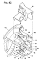
- Fig. 42 is a partial cross -sectional view of a second embodiment of the base assembly restraint system with the rear base cover exploded from the base assembly.
- Figs. 1-5 show a preferred embodiment of the infant travel seat 10 and base assembly 12 of the present invention.
- the base assembly preferably includes a frame 14 comprised of an upper base cover 16, a lower base cover 18, and a rear base cover 20.
- the base assembly has a front end 13 and a rear end 15.
- the upper base cover 16 preferably has a curved platform 22 positioned between opposing side channels 24, 26 to receive a complimentary infant travel seat 10.
- the front end 23 of the curved platform 22 forms a point of highest reference with respect of the curved platform 2 2.
- a pair of angled guiding extensions 28, 30 project outwardly from the curved platform 22 into the opposed side channels 24, 26 at the front end 13 of the base assembly to assist mounting of a complimentary infant travel seat 10 having mating grooves on the base assembly 12.
- the lower base cover 18 is generally horizontal to rest on a vehicle seat 32.
- a base storage compartment 31 can be formed between the curved platform 22 and the lower base cover 18, and can be enclosed by a base storage door 33.
- the base assembly 12 also includes a self-contained restraint system 34 positioned at the rear end 15 of the base assembly 12 to secure the base assembly 12 to a vehicle having an anchor 36 mounted within a vehicle in proximity to the vehicle seat 32.
- a first embodiment of the restraint system 34 in cludes an adjustment assembly 38 coupled to the rear base cover 20 of the frame 14.
- An upper surface 37 of the rear base cover 20 preferably includes an aperture 39 at the upper surface to receive the adjustment assembly 38 within the frame 14 at the center of the frame 14.
- the adjustment assembly 38 is preferably comprised of an adjustment tab 40 and locking assembly 42.
- the locking assembly can be an A-frame type lock such as the A38298 Adjuster by Indiana Mills and Manufacturing, Inc; however, any suitable locking assembly can be used.
- the locking assembly 42 preferably includes an A-frame 44 having first and second ends 4 6, 48.
- the A-frame member 44 is pivotally secured to a housing 50 by a fastener 52 which can be a screw, pin, or any acceptable fastening means.
- the A-frame member 4 4 is secured to the housing 50 such as to limit the rotation of the A -frame member 44 about the fastener 52.
- the housing 46 is preferably is secured to the frame 14.
- the adjustment tab 40 overlays the locking assembly 42 and is pivotally secured to the rear base cover 20 by fastener 53, which can be a screw, pin, or any acceptable fastening means.
- the adjustment tab 40 is substantially L-shaped and has first and second ends 54, 56.
- the first end 54 of the adjustment tab 40 is preferably exposed through the aperture 39 of the rear base cover 20 and has a lip 58 to allow a user to grasp and pull the adjustment tab 40 in a direction toward the front end 13 of base assembly 12.
- the second end 56 of the adjustment tab 40 is received vertically within the frame 14 and forms a substantially parallel plane of symmetry to the plane of the second end 4 8 of the A-frame member 48.
- the second end 56 of the adjustment tab also includes a hook 60 to which a spring 62 is attached to connect the second end 56 of the biasing member 50 to the frame 14.
- the spring limits the rotation of the adjustment tab 40 about the fastener 53 and biases the adjustment tab 4 0 in a manner such as to keep the first end 54 of the adjustment tab 40 in a generally planar orientation with respect to the upper surface 37 of the rear base cover 14. In a resting state, the first end 46 of t he A-frame member 44 pivotally abuts the housing 50.
- the restraint system 34 of the first embodiment further includes a tether 64, preferably in the form of a Y -shaped strap 66 having divergent ends 68, 70 and a central leg end 72.
- the tether 64 may be a simple two ended strap.
- the tether 64 is preferably made of a webbing material and preferably has a width between 1 - 11 ⁇ 2 inches.
- the central leg end 72 of the Y-shaped strap 66 has an exposed portion 74 and an interior portion 76 that is received into the interior of the fr ame 14.
- the interior portion 76 of the central leg end 72 is connected to the divergent ends 68, 70 of the Y-shaped strap member within the interior of the frame 14.
- the interior portion 76 of the central leg end 72 passes between the first end 46 of the A -frame member 44 and the housing 50 of the locking assembly 42, thereby being sandwiched between the first end 46 of the A -frame member 44 and the housing 50 of the locking assembly 42 when the adju stment assembly 38 is in the resting state.
- the interior portion 76 of the central leg end 72 continues upwardly passing through tab slot 78 on the first end 54 of the adjustment tab 40.
- the exposed portion 74 of the central leg 72 then extends out of th e frame 14.
- the exposed portion of the central leg 72 can be tucked into a pocket 75 on the rear base cover 20 (see Fig. 3).
- each divergent end 68, 70 of the Y -shaped strap respectively exits the interior of the frame 14 preferably through side slots 80, 82 (Fig. 3) formed between the upper base cover 16 and the rear base cover 20.
- Each of the divergent ends preferably have a latch securing assembly, which can be a left hand or right hand Mini-Connector, (models A38214AB, and A38213AB) made by Indiana Mills and Manufacturing, Inc. However, any similar securing assembly can be used.
- Each of the latch securing assemblies 84, 86 are secured to one or more anchors 36 mounted within a vehicle, preferably to the chassis, in proximity to a vehicle seat 32 (Fig. 1).
- each latch securing assembly 84 and 86 is secured to a vehicle anchor 36.
- the latch securing assemblies can be sto red in two opposed cavities 88, 90 formed at the rear end 15 of the frame from connection of the rear base cover 20 to the upper base cover 16 (see Fig. 1, 4, 5) and removed when desired to attach to the vehicle.
- a user pulls on the respective divergent end 68, 70 while pulling upward on the lip 58 of the first end 54 of the adjustment tab 40.
- the exposed portion 74 of the central leg 72 of the Y-shaped strap 66 is used to adjust the position of the frame 14 with r espect to a vehicle seat back 87. Pulling the exposed portion 74 of the central leg 72 of the Y-shaped strap 66 upwardly causes the interior portion 76 of the central leg end 72 of the Y-shaped strap to move upwardly through the adjustment assembly 38, thereby creating a greater length of the exposed portion 74 of he central leg end 72 and decreasing the expose d length of both of the divergent ends 68, 70 of the Y-shaped strap 66.
- first end 46 of the A-frame member 44 of the locking assembly 42 is adapted to allow the interior portion 76 of the central leg end 72 of the Y -shaped strap 66 to move upwardly without requiring a user to pull up on the lip 58 of the first end 54 of the adjustment tab 40.
- Fig. 42 depicts a second embodiment of a self-contained restraint system 91 of the base assembly 12 of the present invention preferably comprising at least one ratcheting retractor assembly 92 secured within the interior of the frame 14.
- the ratcheting retractor assembl y 92 preferably comprises a frame 93 having parallel side walls 94, 95.
- a bias member or paw 96 is preferably pivotally coupled to the frame 93 between side walls 94 and 95.
- a spool 97 is rotatably mounted between side walls 94, 95.
- a pair of ratchet wheels 98, 99, each having a plurality of circumferential teeth 100 , 101, are coupled to and rotate with spool 9 7.
- a spring (not shown) is connected to the spool 97 and frame 93 urges the spool 97 to rotate in a slack-reducing or retracting direction to withdraw a tether 102.
- the tether 102 may but need not be fixedly attached or coupled to the spool 97.
- the spool 97 is typic ally urged to move in the retracting direction to retract or withdraw the tether 102 onto the spool 97 in order to reduce the slack in the tether 102.
- the spool 97 is yieldable to allow the tether 102 to be pulled away from the frame 93 in a dire ction opposite the slack-reducing or retracting direction.
- Bias member 96 is coupled to frame 93 such as to be urged against the ratchet wheels 98, 99 in order to engage a pair of opposed teeth 100, 101.
- the bias member 96 and ratchet wheels 98, 99 operat e to prevent rotation of the spool 97 in a direction opposite the slack -reducing or retracting direction.
- Bias member 96 can be connected to a manual actuator to allow a user to disengage the contact between the bias member 96 and the teeth 100, 101 of th e ratchet wheels 98, 99 to allow a user to pull the tether 102 away from the frame 93 in a direction opposite the slack -reducing or retracting direction.
- the frame 93 is adapted to be mounted within the interior of the frame 14 of base assembly 12.
- the tether 102 preferably has a first 103 and second end 104 and a central portion 105.
- the central portion 105 of the tether 102 is received within the interior of the frame 14 and is wrapped around spool 97 when the tether 102 is retracte d.
- the tether 102 from the interior to the exterior of the frame 14 through side slots 80, 82 formed between the upper base cover 16 and the rear base cover 20 and are preferably coupled to a latching mechanism in a similar manner as the divergent ends 68, 70 of the Y-shaped strap member 66 discussed above with respect to the first embodiment of the restraint system 34.
- the base 12 can also be secured to a vehicle having a shoulder harness 120 by one of two opposing belt lo ckoff members 122, 124.
- the upper base 16 cover has a pair of opposed arm extension s 126, 128 connected to the rear base cover 20.
- the opposed arm extensions 126, 128 and rear base cover 20 define opposed apertures 130, 132 in the frame 14 at the rear end 15 of the frame 14.
- the belt lockoff members 122, 124 are each preferably positioned beneath one of the opposed arm extensions 126, 128 of the upper base cover 16 and are secured thereto.
- FIGS 5 and 6 illustrate the interaction betwe en one of the belt lockoff member 124 and one of the opposed arm extensions 128 for exemplary purposes, however, it is preferred that both belt lockoff members and arm extensions are identical.
- Each of the opposed arm extensions 126, 128 includes an interior and an exterior side 134, 136 forming a cavity 135 therebetween. Between the interior and exterior sides 134, 136 and extending through the cavity 135 is a central projection 138 that extends a portion of the length of each of the opposed arm extensio ns 126, 128.
- each belt lockoff member has an upper rough surface 1 40, and lower smooth surface 1 2.
- the upper rough surface 140 preferably has projecting teeth 144, 146 that extend along a portion of the length of the belt lockoff members 122, 124 parallel to the central projection 122 of the opposed arm extensions 126, 128. As shown in Fig. 6, the teeth 144, 146 of the belt lockoff members 122, 124 partially extend into the cavity 135 of the opposed arm extensions 126, 128 and the ce ntral projection of the opposed arm extensions extends between a groove 148 formed between the teeth 144, 146 of the belt lockoff members 122, 124.
- one of the opposing belt lockoff members 122, 124 can be used to secure the shoulder harness 120 to the base assembly 12 in order to prevent the shoulder harness 120 from loosening the fit between the base assembly 12 and the vehicle's safety strap.
- the shou lder harness 120 is abutted by the teeth 144, 146 of the belt lockoff member 122, 124 and the interior and exterior sides 134, 136 and central projection of the arm extension 126, 128 to form a snug fit to prevent the shoulder harness 120 from moving once engaged.
- At least one liquid bubble level 160, 162 is located within the frame 14.
- a portion of the liquid bubble level 160, 162 is preferably received within the frame 14 and positioned in one of two opposed side portions 164, 166 of the upper base cover 16 at the front end 13 of the frame 14.
- the liquid bubble level could be positioned at any suitable location on the frame.
- the base assembly 12 can be installed in either a left or right side of a vehi cle or because a user may access one side of the vehicle when using the base assembly 12, liquid bubble levels 160, 162 are preferably located on the opposed side portions 164, 166 of the upper base cover 16 for the convenience of the user.
- the liquid bub ble levels 160, 162 are preferably curvilinearly shaped to match the curvilinear shape of the respective opposed side portions 164, 166.
- the height adjustment assem bly 70 preferably includes an adjustable foot 172 working in cooperation with an adjustment mechanism 174 to raise and lower the adjustable foot 172.
- the adjustment mechanism 174 includes at least one side recline button, and preferably two opposed side recline buttons 176, 178 received within opposing side apertures 180, 182 on the opposing side portions 164, 166 of the upper base cover 16.
- the opposed side recline buttons 176, 178 have an upper portion 184, 186 and a lower portion 188, 190.
- each side recline button 176, 178 is exposed at the upper side of the opposed side portions 164, 166 of the upper base cover 16 for user interface.
- the lower portion 188, 190 of each side recline button 176, 178 extends into the interio r of the frame 14. As shown in Figs. 7 and 8, the lower side 188, 190 of each opposing side recline button 176, 178 preferably abuts recline bar 1 92.
- Recline brackets 194, 196 extend from the recline bar 192 to recline piston rod 198, having first and second ends 197, 199.
- each recline bracket 194, 196 to ke ep each end 197, 199 of the recline piston rod 198 biased against one of a plurality of opposed angled receiving slots 204, 205 extending from an angled portion 206 of the adjustable foot 172.
- the adjustable foot 172 includes an angled portion 206 having a plurality of opposed angled receiving slots 204, 205 and a horizontal portion 208 adapted to rest upon a vehicle seat 32 in the same plane as the lower base cover 18.
- the adjustable foot 172 is pivotally secured to the upper base cover 16 of the frame 14 at a connection end 210 of the foot opposite the angled portion 206.
- a U -shaped spring 212 is preferably attached to the connection end 210 of the adjustable foot 172 to urge against the upper base cover 16 to bias adjustable foot 172 downwardly.
- the recline bar 192 is urged toward the front end 13 of the frame 14, thereby pulling recline brackets 194, 196 and recline piston rod 198 toward the front end 13 of the frame 14.
- each end 197, 199 of the recline piston rod 198 is sufficiently displaced from the opposed angled receiving slots 204, 205 so as to allow the adjustable foot to pivot in a manner to adjust an angle of the base 12 with respect to the vehicle seat 32.
- the user can release the at least one opposed side recline button 176, 178 causing the each end 197, 198 of the recline piston rod 198 to reengage with one of the plurality of opposed angled receiving slots 204, 205 exte nding from an angled portion 206 of the adjustable foot 172.
- the spacing and number of plurality of opposed angled receiving slots 204, 205 is predetermined.
- At least one of the opposed liquid bubble levels 160, 162 can be used to assist a user in determining a recline position.
- the angled portion 206 of the adjustable foot 172 has a substantially vertical orientation with the rear facing portion 17 of the upper base cover 16 and rear facing portion 21 of the rear base cover 20 due to the angled nature of the angled portion 206 and receiving slots 204, 205.
- the vertical orientation of the base assembly 12 is substantially parallel to the vertical inclination of most vehicle seat backs 87.
- the adjustable foot 172 can be used to adjust the height of the top of the rear base cover 20 to be approximately from 7 to 10 inches from the bottom of the adjustable foot 172.
- the vertical nature of the rear end 15 of the base assembly 12 along with the range of height (approximately 7-10 inches) and width of the base assembly 12 (approximately 14 inches) all cooperate to resist the flipping effect associated with infant car seats in rear end collisions. These height and width measurements are used for exemplary purposes, and the height and width of the rear end 15 of the base assembly may vary.
- Figs. 2 and 12-21 and infant travel seat 10 used in conjunction with the base assembly 12 is shown.
- Figs. 2 and 12-14 show the positional arrangement of the base assembly 12 and infant travel seat 12 is shown.
- the frame 14 of the base assembly 14 includes a curved platform 22 positioned between opposing side channels 24, 26.
- Two angled guide extensions 28, 30 extend from the curved platform 22 at the rear end 15 of the frame 12.
- the angled guid e extensions 28, 3 0 each preferably have a curved surface 220, 222 facing toward end 15 of the frame 14, an angled surface 224, 226, and a vertical surface 228, 230.
- base cover 16 of the frame 14 further includes two opposed rear guide extensions 232, 234 .
- the infant travel seat 10 includes a shell 235 having an interior side 236 an exterior side 238, a head end 240 and a foot end 242.
- the exterior side 238 of the shell 235 preferably includes a pair of opposed rails 256, 258 and a pair of opposed grooves 244, 246 to mate with the angled guiding extensions 28, 30 of the base assembly 12, and a pair of opposed grooves 248, 250 at the foot end 42 to mate with the rear guide extensions of the base assembly 12.
- each of the opposed grooves 244, 24 6 (only one being shown) have an arcuate surface 252 and a generally straight, but angled, surface 254.
- the seat 10 can be mounted on the base assembly 12 by contacting the curved su rface 252 of the opposed grooves 244, 246 with the curved surface 220, 222 of the angled guiding extensions 28, 30 of the base assembly 12 and pushing the seat 10 toward end 15 of the base assembly 12 (Fig. 12), or by contacting the angled surface 254 of the opposed side grooves 244, 246 of the seat 10 with the angled surface 224, 226 of the angled guiding extensions 28, 30 of the base 12 and pushing the seat 10 in a direction toward end 13 of the base assembly 12 (Fig. 13).
- the opposed rails 256, 258 of the seat 10 are received within the respective opposed side channel 24, 26 of the base assembly 12 (Fig. 14) and the seat 10 rests upon platform 22 of the base assembly 12 (Fig. 14).
- the infant travel seat 10 is preferably secured to the base assembly 12 at four engaging points.
- the opposed side portions 164, 166 of the upper base cover 16 each have an opposed side recess 260, 262 facing a respective one of the opposed side channels 24, 26.
- the base assembly 12 includes a pair of pivotable securing latches 26 4, 266, which can be hooks or any other suitable securing device, positioned at the rear end 15 of the base 12, and preferably extending through a pair of apertures 272, 274 extending through the rear base cover 16.
- Hooks 26 4, 266 are preferably positioned so a head 26 8, 270 of the hook 264, 266 faces the rear end 15 of the base 12 (Fig. 7).
- the shell 235 of the seat 10 defines opposed side apertures 276, 278 extending through a side portion 280, 282 of the shell 235.
- the shell further defines opposed receptacles 284, 286 (Fig. 2) extending through the foot end 242 of the shell 235.
- the head end 240 of the shell 235 further defines an aperture 288 for receiving a spring -biased handle 290 of an actuator assembly 292 (Figs. 2, 15).
- the actuator assembly 292 (Fig. 16) is positioned on the interior side 236 of the shell 235 and the handle 290 of the actuator assembly 292 is accessible through aperture 288.
- the actuator assembly 292 preferably has two arms 294, 296 extending from the handle 292 down the sides of the interior 236 of the shell 235.
- the arms preferably have angled slots 298, 300 to receive pins 302, 304 from spring-biased side mounting assemblies 306, 308, respectively.
- S ide mounting assemblies 306, 308 include retractable securing projections 310, 312, such as in the form of a flipper.
- the retractable securing projections 301, 312 extend from the interior of the shell 235 into side apertures 276, 278.
- the spring biased side mounting assemblies 306, 308 bias the retractable securing projections 310, 312 to extend through side apertures 276, 278.
- the retractable securing projections 310, 312 are adapted to form a complimentary secured engagement with the opposed side recess 260, 262 of the frame 14 of the base assembly 12 when the seat 10 is mounted on the base assembly 12.
- the arms 294, 296 of the actuator assembly 292 are each preferably connected to a cable 314, 316, having first 318, 320 and second 322, 324 ends .
- the first end 318, 320 of each cable 314, 316 being connected to arms 294, 296, and the second end 322, 324 of each cable 314, 316 being connected to biasing members 326, 328, respectively.
- the biasing members 326, 328 are positioned at and received within the opposed receptacles 284, 286 of the shell 235, respectively.
- Each biasing members 326, 328 includes a first end 330, 332 and second end 334, 336 end.
- the first ends 330, 332 of the biasing members 326, 328 are pivotally connected to the shell 335, and the second ends 334, 336 of the biasing members 326, 328 are coupled to cables 314, 316 of actuator assembly 292.
- the biasing members 326, 328 are biased toward the foot end 242 of the shell 235 in a resting state.
- the opposed receptacles 284, 286 of the shell 235 are configured to receive the opposed securing latches or hooks 264, 266 of the base assembly 12 when the seat 10 is mounted on the base assembly 12.
- the engagement of the securing latches or hooks 264, 266 of the base assembly 12 to the receptacles 284, 286 of the seat 10 prevents the seat 10 from rotating or moving upwardly.
- biasing members 326, 328 are pivoted toward the head end 240 of the shell 235 forcing the securing latches or hooks 264, 266 of the base assembly 12 out of receptacles 284, 286 , thus releasing the engagement between the securing latches or hooks 264, 266 of the base assembly 12 and the receptacles 284, 286 of the seat 10.
- the retractable securing projections 310, 312 of the infant travel seat 10 are adapted to be mounted to a stroller 338 having oppos ed complimentary receiving slots 339 (only one being shown).
- a lip 340 on the exterior of the shell 235 proximate to the head end 240 of the shell 235 is adapted to rest on tray 342 of the stroller 338 (see Fig. 41).
- the seat preferably has an infant restraint harness 350, in phantom, made of a webbing material.
- the vehicle restraint harness is preferably a Y-shaped strap having divergent ends 352, 354 and a central leg end 356.
- a locking mechanism 358 is secured to each of the divergent ends 352, 354 of the Y -shaped strap.
- the locking mechanism 358 has male and female connectors 360, 362.
- the female connector 362 has front and back sides 364, 366 defining a groove 368.
- the front side 364 of the female connector 362 further defines an aperture 370.
- the male connector 360 has front and back sides 272, 274 and a receiving end 276, the receiving end 276 adapted to be received within the groove 368 of the female connector 362.
- the front side 272 of the mal e connector 360 preferable includes a flexible button 378 receivable within the aperture 370 of the female connector 362. When end 376 of the male connector 360 is inserted within the groove 368 of the female connector 362, the flexible button 378 of the male connector 360 is received by the aperture 370 of the female connector 362. To disengage, a user depress es the flexible button 378.
- the seat 10 further includes a harness adjusting assembly 380.
- the harness adjusting assembly 38 0 comprises a locking assembly 382 and an adjusting tab 384.
- the adjustment assembly 380 operates in a similar fashion to the base adjustment assembly 38, described above and incorporated by reference, and is not repeatedly described at length herein.
- Figs. 22-31 illustrate a first embodiment of opposed handle attachment assemblies 400, 402 for securing each arm 406, 408 of a carrying handle 404 to an infant travel seat 10.
- the handle attachment assemblies 400, 402 preferably include a hub receiving portion 410, 412 of each arm 406, 408 adapted to be secured to opposing side hubs 414, 416 of the shell 235 of the seat 10 (see Fig. 1). Only one of the opposed handle attachment assemblies 400, 402 will be described in detail below, however, both of the attachment assemblies 400, 402 are preferably identical.
- the hub receiving portion 412 includes an actuating assembly 418 comprising a pivotable member 420, a stationary member 422, and a spring-biased locking member 424.
- the arm 408 of the handle 404 defines an aperture 426 proximate to the hub receiving portion 412 for receiving the pivotable member 420 and stationary member 422.
- the stationary member has a cover end 428 and an interior end 430 received within arm 408.
- the pivotable member 420 includes a lever end 432 and a biasing end 434 end.
- the pivoting member 420 is adapted to be pivotally secured to stationary member 422 at pivot point 436 (Fig. 23).
- Pivotable member 420 and stationary member 422 are received withi n aperture 426 such that the cover end 428 of the stationary member 422 is substantially flushed with the exterior surface of the arm 408 and lever end 432 of pivotable member extends outwardly through aperture 426.
- Stationary member 422 is secured to arm 408 at securing points 438, 440 when received in arm 408.
- Pivotable member 420 is pivotally secured to stationary member 422 and arm 408 at pivot point 436 when received in arm 408.
- edge 442 of the stationary member 422 limits the downward rotation of pivotable member 420 by abutting complimentary edge 444, of pivotable member 420.
- the interior surface 446 of the cover end 428 of stationary member 222 limits the upward rotation of pivotable member 420 by abuttin g projection 448.
- Pivotable member 420 preferably extends through aperture 426 such that biasing end 434 is positioned within the hub receiving portion 412.
- Spring-biased locking member 424 has a first end 450 for engaging a complimentary locking mechanis m, and a second end 452 positioned within the hub receiving portion 412 to abut biasing end 434 of the pivotable member 420.
- the second end 452 of the locking member 424 has an angled cam surface 454 that abuts a complimentary angled cam follower surface on the biasing end 434 of the pivotable member 420.
- the second end 452 of the locking member 424 also preferably includes a pair of springs 458 460 to bias the locking member 424 away from the hub receiving portion 412 and toward opposed side hub 416 of t he shell 235.
- opposed side hub 414 has a central projection 462 positioned on a central axis CA (Fig. 22) and a plurality of circumferential projections 464 extending toward the center of the hub 416 and positioned radially to the central projection 462.
- the central projection 462 is used to secure the hub receiving portion 412 to th e side hub 416 of the shell 235 along the central axis CA so that the carrying handle 404 can rotate on a radial axis with respect to the central axis CA.
- the circumferential projections consist of six diametrically opposed minor projections 466 and alternated between six diametrically opposed major projections 468. However, the number of major and minor projections 466, 468 can vary.
- the locking member 424 preferably has a central aperture 470 to receive the central projection 462 of the hub 416.
- the locking member 424 also preferably includes two opposed grooves 472, 474 to positioned in an axis perpendicular to the axis of the first and second ends 450, 452 of the locking member 424. Each of the opposed grooves 472, 474 are configured to receive and be complimentary to the minor projections 466 of the hub 416.
- the opposed grooves 472, 474 of the locking member 424 are secured to a pair of diametrically opposed minor projections 466 in an axis perpendicular to the central axis CA of connection between the hub receiving portion 412 of the carrying handle 404 and the side hub 416 of the shell 235.
- the locking member 424 can be displaced from the minor projections 466 by pressing lever end 432 to pull the locking member 424 toward the hub receiving portion 412 and away from opposed side hub 416 of the shell 235.
- the plurality of circumferential projections 464 are of such a height so as to permit the locking member 424 to rotate radially about the central projection 462 when displaced from the minor projections 466 (see Fig. 26).
- the locking member 424 can be secured to the minor projections 466 to allow the carrying handle 404 to be adjusted between three positions.
- the side hub 316 preferably includes two diametrically opposed abutting projections positioned on the circumference of the hub 416 having a sufficient length extending paralle 1 to the central axis CA to abut the locking member 424 when displaced from projections 466 and prevent the locking member 424 from rotating greater than 180 degrees.
- Figs. 36-40 illustrate a second embodiment of opposed handle assemblies 500, 502 for securing each arm 406, 408 of a carrying handle 404 to an infant travel seat 10.
- the handle attachment assemblies 500, 502 (only one being shown) preferably include a hub receiving portion 510, 512 (only one being shown) of each arm 406, 408 adapted to be sec ured to opposing side hubs 514, 516 (only one being shown) of the shell 235 of the seat 10 (see Fig. 1).
- the hub receiving portions 510, 512 are secured to the opposing side hubs along a central axis CA similar to the first embodiment. Only one of the opposed handle attachment assemblies 500, 502 will be described in detail below, however, both of the attachment assemblies 500, 502 are preferably identical.
- the hub receiving portion 512 includes actuating assembly 516 comprising a button 518 and a spring biased locking member 520.
- the button has first and second ends 520, 524.
- the second end 524 of the button has opposed sides 526, 528 and is adapted to be received within a slot 530 in arm 408 proximate to the hub receiving portion 512.
- the sides 526, 528 of the button 518 define a channel 532.
- the first end 522 of the button 518 extends outwardly through slot 530 of arm 408.
- the spring biased locking member 5 20 preferably comprises a locking end 534 and a biasing end 536.
- the locking end has a lockin g head 538 that extends parallel to the central axis CA.
- the locking end 534 also includes a centrally located ovate aperture 540 extending along the central axis CA.
- the biasing end 536 of the spring biased locking member 520 is preferably defines a groove 544 surrounded by two opposed abutting members 546, 548.
- the groove is adapted to be received within the channel 532 of sides 526, 528 of the button 518.
- a spring 529 is connected to the biasing end 536 to bias the spring biased locking member away from button 518.
- side 526 of button 518 has an angled surface 550 that abuts a complimentary angled surface 552 of the abutting member 548, and urges the button out of slot 530 in a resting state.
- angle d surface 550 of button 518 slides against a complimentary angled surface 552 of abutting member 548 and pulls the locking member 520 in a direction perpendicular to the central axis CA toward button 518.
- the side hub 516 has a central projection 542 posit ioned on the central axis CA and a plurality of circumferential projections 554 extending toward the center of the hub 516 and positioned radially to the central projection. As shown in Figs. 37-40, the plurality of circumferential projections 554 can con sist of four diametrically opposed minor projections 556 and two diametrically opposed major projections 558. However, the number of projections 554 may vary.
- the locking head 538 of the locking member 520 is configured to have two opposed engaging heads 560, 562.
- Each of the engaging heads 560, 562 is configured to fit between two of the plurality of circumferential projections 554 in an axis perpendicular to the central axis CA to secure the handle 404 in a stationary position.
- the carrying handle 404 is adapted to be radially adjusted about the central axis CA.
- the engaging heads 560, 562 of the locking member 520 are displaced from projections 554 by pressing the first end 522 of button 518 downward to pull the locking member 520 toward button 518 and allowing central projection 542 to slide along the ovate aperture 540.
- the minor projections 556 have a width extending perpendicular to the central axis CA so as to permit the locking head 538 to rota te radially about the minor projections 556 when displaced from the securement between the projections 554. As shown in Figs.
- the locking head 538 can be secured between projections 554 to allow the carrying handle 404 to be adjusted between three positions.
- the side hub 516 preferably includes two diametrically opposed major projections 558 having a sufficient width extending perpendicular to the central axis CA to abut the locking head 538 when displaced from projections 554 and prevent the locking head 538 from rotating greater than 180 degrees.
- Figs. 1, 22, and 31 illustrate a ratcheting canopy 580 that can be attached to the infant travel seat 10.
- the ratcheting canopy preferably comprises a pair of rings 582, 584 that can be secured to the ex terior surface of side of hubs 414, 416 of the shell 235.
- the exterior surface of side hub 416 include s a plurality of circumferential projections 586 extending radially around the hub 416.
- the interior surface of ring 584 include s a plurality of circumferential projections 588 extending radially around the ring 584 to mate with the circumferential projections 586 of the hub 416 to form a secure connection between t he ring 584 and the hub 416.
Abstract
Description
Claims (44)
- An infant travel seat base comprising:a frame dimensioned to rest upon a vehicle seat and defini ng front and rear portions and a center line;an adjustment assembly that is coupled to the frame and includes a locking element, the adjustment assembly is positioned at a selected one of the front and rear portions of the frame; anda tether including a free end which is releasably secured in the locking element of the adjustment assembly, and at least one securing end adapted to be secured to an anchor mounted within the vehicle so that movement of the tether through the locking element adjusts the posit ion of the securing end with respect to the frame.
- The base of claim 1, wherein the frame defines upper and lower planes and the adjustment assembly is positioned between the planes.
- The base of claim 2, wherein the adjustment assembly is positioned on the center line of the frame.
- The base of claim 1, wherein the adjustment assembly is positioned on the center line of the frame.
- The base of claim 1, wherein the tether further comprises a connection portion that is contained within the frame and joins the free end to the securing end.
- The base of claim 1, wherein the locking element is spring biased and positioned on the center line of the frame.
- The base of claim 6, wherein the length of the tether is adjusted by pulling the free end of the tether away from the frame.
- The base of claim 7, wherein pulling the free end of the tether away from the frame adjusts the length of the securing end of the tether with respect to the frame.
- The base of claim 1, wherein the frame further compris es a cavity sized to receive an excess length of the free end of the tether.
- The base of claim 1, wherein the tether is Y-shaped and the opposed divergent ends of the Y each include a securing end of the tether and the central leg end of the Y is the free end.
- The base of claim 10, wherein each securing end is a locking member adapted to be secured to an anchor mounted within the vehicle.
- The base of claim 11, wherein the locking element is spring biased and positioned on the center line of the frame.
- The base of claim 12, wherein the length of the divergent ends is adjusted by pulling the central end away from the frame.
- The base of claim 11, further comprising a cavity positioned at the rear portion of the frame adapted to receive the locking members.
- The base of claim 10, wherein the frame further comprises a cavity proximate to the adjusting assembly and sized to receive the central leg end of the Y-shaped strap.
- The base of claim 10, wherein the Y-shaped strap has a width within the range of 1 - 1½ inches.
- A restraint system for an infant travel seat base comprising:an infant travel seat base that is dimensioned to rest upon a vehicle seat and defines front and rear portions, upper and lower plane s, and a center line;at least one adjustment assembly that is coupled to the base and positioned at a selected one of the front and rear portions of the base, the adjustment assembly including a locking element; andat least one tether including a central portion releasably secu red in the locking element and two end portions adapted to be secured to an anchor mounted within the vehicle so that movement of the tether through the locking element adjusts the position of the end portions with respect to the base.
- The restraint system of claim 17, wherein the at least one adjustment assembly further comprises a retractor assembl y that is biased to automatically draw the central portion of the tether towards the retractor assembly and adjust a length of the two end portions of the tether with respect to the base.
- A base for supporting an infant travel seat comprising:a frame, the frame having a front end, a rear end, two oppos ed sides, an upper surface that receive s an infant travel seat, and a lower surface configured to rest upon a vehicle seat; andat least one liquid bubble level positioned within the frame.
- The base of claim 19, wherein the at least one liquid bubble level is curvilinearly shaped.
- The base of claim 20, further comprising a pair of liquid bubble levels, each liquid bubble level being positioned at one of the opposed sides of the frame.
- The base of claim 20, wherei n the opposed sides of the frame have a curvilinear portion and the at least one liquid bubble level is positioned at the curvilinear portion of at least one of the opposed sides of the frame.
- The base of claim 2 2, wherein the curvilinear portion of the opposed sides of the frame is positioned proximate to the front end of the frame.
- The base of claim 19, further comprising and adjustable foot pivotally connected to the frame and positioned beneath the rear end of the frame, the adjustable foot being adapted to selectively change the angle of the frame with respect to the vehicle seat.
- An infant travel seat comprising:wherein the handle actuator is adapted to disengage the radial engagement of the locking member with the at least one circumferential projection by displacing the locking member sufficiently from the plurality of circumferential projections to allow the locking member to rotate on a radial axis with respect to the central axis and adjust a position of the radial engagement of the locking member with at least one the plurality of circumferential projections.a shell including a seating portion and two opposing side hubs, each hub having a central axis and at least one of the hubs having a plurality of circumferential projections extending toward the center of the hub and positioned radial to the central axis;a handle rotatably connected to the frame including two arms, each arm having a hub receiving portion, the hub receiving portion of each arm adapted to be secured to one of the hubs of the shell; andat least one locking member connected to the handle, wherein the locking member has at least one engaging portion releasably engageable with at least one of the plurality of circumferential projections, the locking member being biased by a handle actuator disposed on the handle to form a radial engagement with at least o ne of the circumferential projections;
- The infant travel seat of claim 25, wherein rotation of the locking member on the radial axis allows the handle to rotate and be locked into a plurality of rotational positions.
- The infant travel seat of claim 25, wherein the hub receiving portion of each arm is secured to the corresponding opposing side hubs of the shell at the central axis of each hub.
- The infant travel seat of claim 25, wherein the at least one hub further comprises a circular protrusion extending along the central axis and the at least one locking member further comprises an ovate aperture to receive the circular protrusion, wherein when the locking member is adjusted, the ovate aperture slides along the circular protrusion in an axial direction perpendicular to the central axis.
- The infant travel seat of claim 28, wherein the locking member includes two opposed engaging portions wherein each portion is releasably engaged with at least one of the circumferential projections to form two opposing radial engagements between the locking member and the circumferential projections.
- The infant travel seat of claim 29, further comprising two diametrically opposed abutting projections positioned on a circumference of the hub and having a length extending toward the central axis sufficient to prevent the at least one locking member from rotating greater than 180 degrees.
- The infant travel seat of claim 29, wherein each of the opposed engaging portions of the locking member are releasably engaged between two of the circumferential projections.
- The infant travel seat of claim 25, wherein the handle actuator moves the at least one locking member in an axial direction parallel to the first axial direction to allow the locking member to rotate on a radial axis with respect to the central axis and adjust a position of the radial engagement of the locking member with at least one the plurality of circumferential projections.
- The infant travel seat of claim 32, wherein the locking member includes two opposed engaging portions wherein each portion is releasably engaged with at least one of the circumferential projections to form two opposing radial engagements between the locking member and the circumferential projections.
- The infant travel seat of claim 33, further comprising two diametrically opposed abutting projections positioned on a circumference of the hub, the abutting projection having a length extending parallel with respect to the central axis sufficient to prevent the at least one locking member from rotating greater than 180 degrees.
- The infant travel seat of claim 32, wherein the at least one engaging portion of the locking member defines a groove to receive and partially surround at least one the plurality of circumferential projections.
- An infant travel system comp rising:a base assembly comprising:front and rear ends and two opposed sides that define a generally rectangular cuboid having upper and lower surfaces;the lower surface configured to rest upon a vehicle seat;the upper surface configured to receive a complimentary infant travel seat;opposed securing latches positioned at one end of the base for securing an infant travel seat; andan infant travel seat comprising:a shell having a head end, a foot end, and opposing sides defining a seat, the seat havin g an interior and exterior;the shell further defining opposed receptacles positioned at the foot end of the seat, the opposed receptacles configured to receive the opposed securing latches of the base; andan actuating assembly located on the interior of the seat to control the engagement between the opposed receptacles of the seat and the opposed securing latches of the base.
- The infant travel system of claim 36, wherein the actuating assembly has a spring biased handle accessible through an aperture on the exterior of the head end portion of the shell to control the engagement between the opposed receptacles of the seat and the opposed securing latches of the base.
- The infant travel system of claim 36, wherein:wherein the retractable securing projections are biased to project away from the exterior of the s eat through the opposed apertures and the actuating assembly is configured to retract the retractable securing projections toward the interior of the seat to control the engagement between the retractable securing projections of the seat and the opposed recesses of the base.the upper surface of the base furt her defines opposed side recesses for receiving complimentary securing projections on the infant travel seat;the shell of the seat further defines opposed side apertures positioned at the opposed sides of the seat, each of the opposed apertures are config ured to receive a retractable securing projection coupled to the actuating assembly and adapted to mate with the opposed side recesses of the base;
- The infant travel system of claim 38, wherein the actuating assembly has a spring biased handle accessible through an aperture on the exterior of the head end portion of the shell to control the engagement between the opposed receptacles of the seat and the opposed securing latches of the base and the engagement between the retractable securing projections of the seat and the opposed recesses of the base.
- The infant travel system of claim 38, wherein the retractable securing projections are retractable flippers.
- The infant travel system of claim 38, wherein the opposed side recesses of the base are positioned at the front end of the base.
- The infant travel system of claim 36, wherein the opposed securing latches of the base further comprise spring biased hooks.
- The infant travel system of claim 42, wherein the spring biased hooks are positioned to face a vehicle seat back when the base is placed on a vehicle seat.
- The infant travel system of claim 43, wherein:wherein the biasing members are positioned to be biase d toward the interior of the s eat and the actuating assembly is configured to pivot the biasing members toward the exterior of the s eat to force the hooks of the base out of the receptacles of the seat when the seat is disengaged from the base.each of the opp osed receptacles of the seat are configured to receive a biasing member having first and second ends, the first end pivotally connected to the shell and the second end coupled to the actuator assembly;
Applications Claiming Priority (2)
| Application Number | Priority Date | Filing Date | Title |
|---|---|---|---|
| US56730704P | 2004-04-30 | 2004-04-30 | |
| US567307P | 2004-04-30 |
Publications (4)
| Publication Number | Publication Date |
|---|---|
| EP1591307A2 true EP1591307A2 (en) | 2005-11-02 |
| EP1591307A3 EP1591307A3 (en) | 2009-10-21 |
| EP1591307B1 EP1591307B1 (en) | 2014-06-11 |
| EP1591307B2 EP1591307B2 (en) | 2022-02-09 |
Family
ID=34939538
Family Applications (1)
| Application Number | Title | Priority Date | Filing Date |
|---|---|---|---|
| EP05103427.0A Active EP1591307B2 (en) | 2004-04-30 | 2005-04-27 | Infant travel system |
Country Status (4)
| Country | Link |
|---|---|
| US (7) | US7597396B2 (en) |
| EP (1) | EP1591307B2 (en) |
| ES (1) | ES2479965T5 (en) |
| PT (1) | PT1591307E (en) |
Cited By (18)
| Publication number | Priority date | Publication date | Assignee | Title |
|---|---|---|---|---|
| GB2468965A (en) * | 2009-03-24 | 2010-09-29 | Graco Childrens Prod Inc | Infant car seat base |
| DE202010008803U1 (en) | 2010-10-13 | 2011-01-13 | Curt Würstl Vermögensverwaltungs-Gmbh & Co. Kg | Seat anchoring element for child safety seats or baby carrier |
| CN102627080A (en) * | 2012-04-26 | 2012-08-08 | 江苏幸运宝贝安全装置制造有限公司 | Reversing deadlock mechanism for restraint system of vehicle-mounted safety child car seat |
| GB2493300A (en) * | 2010-07-15 | 2013-01-30 | Bp Childrens Prod Hk Co Ltd | Infant seat and method of installing the same in a vehicle |
| US20140008951A1 (en) * | 2012-07-03 | 2014-01-09 | Kids Ii, Inc. | Pivotal handle lock/release mechanism for child car seat |
| EP2923917A1 (en) * | 2014-03-14 | 2015-09-30 | Dorel France | Child restraint system |
| CN105774607A (en) * | 2016-03-17 | 2016-07-20 | 苏州纪宝儿童用品有限公司 | Fastening structure for child seat bucket and base |
| CN106032114A (en) * | 2015-03-13 | 2016-10-19 | 明门香港股份有限公司 | Angular adjustment device, and vehicle safety seat and infant carrier with same |
| US10039389B2 (en) | 2017-01-06 | 2018-08-07 | Xiamen Baby Pretty Products Co., Ltd. | Crib |
| CN111688552A (en) * | 2019-03-13 | 2020-09-22 | 宝得适儿童安全公司 | Child safety seat |
| CN111923794A (en) * | 2019-05-13 | 2020-11-13 | 明门瑞士股份有限公司 | Baby car seat |
| EP3763564A1 (en) * | 2019-07-10 | 2021-01-13 | Maxi Miliaan B.V. | Child seat transporting system and safety part suitable for such a child seat transporting system |
| WO2021245425A1 (en) * | 2020-06-04 | 2021-12-09 | Strolleazi Group Limited | Child car seat system and child transportation system |
| US11376999B2 (en) | 2019-07-10 | 2022-07-05 | Dorel Juvenile Group, Inc. | Infant carrier |
| EP4035936A1 (en) * | 2011-07-01 | 2022-08-03 | Wonderland Switzerland AG | Child seat |
| US11472316B2 (en) | 2019-07-10 | 2022-10-18 | Dorel Juvenile Group, Inc. | Coupling mechanism as well as a child seat transporting system provided with at least one such coupling mechanism |
| US11541786B2 (en) | 2019-07-25 | 2023-01-03 | Dorel Juvenile Group, Inc. | Infant carrier |
| WO2024052374A1 (en) * | 2022-09-06 | 2024-03-14 | Wonderland Switzerland Ag | Adjustment structure, base assembly, top rod structure, and child safety seat |
Families Citing this family (87)
| Publication number | Priority date | Publication date | Assignee | Title |
|---|---|---|---|---|
| US7798571B2 (en) * | 2005-05-02 | 2010-09-21 | Graco Children's Products Inc. | Child vehicle safety seat |
| US20080067845A1 (en) * | 2006-02-28 | 2008-03-20 | Britax Child Safety, Inc. | Carry handle seat latch for child safety seat |
| US7452031B2 (en) * | 2006-11-10 | 2008-11-18 | Evenflo Company, Inc. | Multi-adjustable child seat with detachable softgoods attachment |
| US7950738B2 (en) * | 2007-09-05 | 2011-05-31 | Cosco Management, Inc. | Latch belt storage system for juvenile vehicle seat |
| US7926874B2 (en) * | 2007-09-06 | 2011-04-19 | Cosco Management, Inc. | Belt-anchor system for juvenile vehicle seat |
| EP2042404B1 (en) * | 2007-09-25 | 2010-11-24 | Ting-Yu Chen | Baby stroller with portable cradle |
| CN101659224B (en) * | 2008-06-25 | 2011-11-23 | 明门香港股份有限公司 | Child chair |
| US8141950B2 (en) * | 2008-08-07 | 2012-03-27 | Immi | Single retractor lower anchor connection system |
| EP2323888B1 (en) | 2008-08-15 | 2015-01-21 | Artsana Usa Inc. | Stroller |
| NL1036453C2 (en) * | 2009-01-23 | 2010-07-26 | Maxi Miliaan Bv | Child vehicle seat. |
| US7988230B2 (en) * | 2009-01-26 | 2011-08-02 | Cosco Management, Inc. | Juvenile vehicle seat with lap belt lock-off mechanism |
| US8474907B2 (en) * | 2009-07-05 | 2013-07-02 | Graco Children's Products Inc. | Car seat installation and recline mechanism |
| US8393678B2 (en) * | 2009-12-21 | 2013-03-12 | Goodbaby Child Product Co., Ltd. | Infant child restraint system |
| US8393674B2 (en) | 2010-01-11 | 2013-03-12 | Goodbaby Child Product Co., Ltd. | Infant child restraint system |
| CN103153750B (en) | 2010-03-23 | 2016-12-07 | 雅沙娜美国股份有限公司 | There is the stroller of moved seat adnexa |
| CN201665233U (en) * | 2010-03-24 | 2010-12-08 | 中山市隆成日用制品有限公司 | Infant safety chair latching mechanism |
| US8262161B2 (en) | 2010-05-04 | 2012-09-11 | Cosco Management, Inc. | Child restraint for vehicle |
| CN102241255B (en) * | 2010-05-13 | 2013-06-05 | 荷兰商伍轮实业股份有限公司 | Latch device for coupling a carrier to a stroller frame and a stroller frame capable of assembling the carrier |
| US8256840B2 (en) * | 2010-06-10 | 2012-09-04 | Britax Child Safety, Inc. | Apparatus and method for attaching a child safety seat to a vehicle seat |
| US8882196B2 (en) | 2010-07-15 | 2014-11-11 | Wonderland Nurserygoods Company Limited | Child safety seat |
| EP2407341B1 (en) * | 2010-07-15 | 2016-05-25 | Wonderland Nurserygoods Company Limited | Child safety seat assembly |
| US8998312B2 (en) * | 2010-10-29 | 2015-04-07 | Wonderland Nurserygoods Company Limited | Infant safety seat |
| US8567862B2 (en) * | 2011-01-18 | 2013-10-29 | Wonderland Nurserygood Company Limited | Child safety seat assembly |
| CN102848945B (en) * | 2011-06-27 | 2016-03-30 | 明门香港股份有限公司 | Child seat |
| US9452695B2 (en) * | 2011-08-19 | 2016-09-27 | Baby Trend, Inc. | Child car seat and base |
| CN202345738U (en) * | 2011-09-22 | 2012-07-25 | 明门香港股份有限公司 | Children cart |
| US8840184B2 (en) * | 2011-10-06 | 2014-09-23 | Thorley Industries Llc | Child restraint system with automated installation |
| CN103057443B (en) | 2011-10-19 | 2016-04-27 | 明门香港股份有限公司 | Child seat |
| US8967715B2 (en) | 2011-11-07 | 2015-03-03 | Graco Children's Products Inc. | Anchor latch system for child restraint systems and child car safety seats |
| US9016781B2 (en) * | 2011-11-17 | 2015-04-28 | Wonderland Nurserygoods Company Limited | Child safety seat assemblies |
| CN103129424B (en) * | 2011-12-02 | 2015-06-24 | 明门香港股份有限公司 | Children car seat |
| US9688299B2 (en) * | 2012-05-01 | 2017-06-27 | Safe-Strap Company, Inc. | Infant carrier holder |
| US9540026B2 (en) | 2012-05-01 | 2017-01-10 | Safe-Strap Company, Inc. | Infant carrier holder |
| CN103386906B (en) | 2012-05-10 | 2016-04-13 | 宝钜儿童用品香港股份有限公司 | Child seat |
| CN103507671B (en) * | 2012-06-27 | 2015-11-25 | 宝钜儿童用品香港股份有限公司 | Engaging indicating device and there is the child safety seat of this engaging indicating device |
| US10220734B2 (en) | 2013-03-05 | 2019-03-05 | Pidyon Controls Inc. | Car seat |
| US9487110B2 (en) | 2014-03-05 | 2016-11-08 | Pidyon Controls Inc. | Car seat |
| US8911015B2 (en) | 2013-03-05 | 2014-12-16 | Yochanan Cohen | Car seat |
| CN203580703U (en) | 2013-03-15 | 2014-05-07 | 克斯克管理公司 | Child restraint system |
| US8960794B2 (en) * | 2013-04-02 | 2015-02-24 | John David St. Pierre | Child carrier and car seat combination |
| CN203318198U (en) * | 2013-06-07 | 2013-12-04 | 中山市隆成日用制品有限公司 | Dual-purpose releasing mechanism for lifting basket type automobile seat |
| US9756961B2 (en) * | 2013-06-14 | 2017-09-12 | Wonderland Nurserygoods Company Limited | Adjusting mechanism and related child carrier |
| US9108659B2 (en) | 2013-08-07 | 2015-08-18 | Recaro Child Safety Llc | Stroller with selectively hidden adapters |
| WO2015027275A1 (en) * | 2013-08-27 | 2015-03-05 | Infa-Secure Pty Ltd | A child restraint system for a vehicle |
| CN203543730U (en) * | 2013-10-21 | 2014-04-16 | 中山市隆成日用制品有限公司 | Infant safety seat and base seat buckling and releasing mechanism |
| US9187014B2 (en) * | 2013-10-22 | 2015-11-17 | Goodbaby Child Product Co., Ltd. | Adjustable foot for an infant car seat base |
| CN104553902B (en) | 2013-10-23 | 2018-01-02 | 明门香港股份有限公司 | Child safety seat |
| CN104676525A (en) * | 2013-12-02 | 2015-06-03 | 深圳市海洋王照明工程有限公司 | Explosion-proof lamp |
| US9308839B1 (en) | 2014-03-04 | 2016-04-12 | Michael Gleckler | Child car seat transportion system |
| WO2015161281A1 (en) | 2014-04-17 | 2015-10-22 | Hni Technologies Inc. | Chair and chair control assemblies, systems, and methods |
| EP3142891B1 (en) * | 2014-05-16 | 2021-01-06 | Dorel France | Child restraint |
| US10077062B2 (en) | 2014-07-29 | 2018-09-18 | Veer Gear, Llc | Wagon with adapter for installing child seat |
| US20160059746A1 (en) * | 2014-08-28 | 2016-03-03 | Goodbaby Child Product Co., Ltd. | Adjustable Foot For A Child Car Seat Base |
| US9616782B2 (en) | 2014-08-29 | 2017-04-11 | Pidyon Controls Inc. | Car seat vehicle connection system, apparatus, and method |
| US9308838B2 (en) | 2014-09-09 | 2016-04-12 | Britax Child Safety, Inc. | Center-pull latch mechanism |
| US9873359B2 (en) * | 2014-12-23 | 2018-01-23 | Wonderland Nurserygoods Company Limited | Child safety seat |
| US10351027B2 (en) | 2015-01-29 | 2019-07-16 | Artsana Usa, Inc. | Carry handle release mechanism for a child seat |
| CN108025660B (en) | 2015-05-12 | 2021-06-25 | 皮迪耶恩控制公司 | Automobile seat and connecting system |
| CA2930939C (en) * | 2015-05-27 | 2019-02-26 | Wonderland Nurserygoods Company Limited | Child safety seat and support base thereof |
| US9758068B2 (en) * | 2015-06-22 | 2017-09-12 | Wonderland Nurserygoods Company Limited | Child restraint with recline |
| CA2940813C (en) | 2015-09-03 | 2017-08-22 | Wonderland Nurserygoods Company Limited | Infant carrier |
| EP3376908A4 (en) * | 2015-11-16 | 2019-07-24 | Mobius Protection Systems Ltd. | Baby seat |
| CN108778892A (en) | 2016-03-08 | 2018-11-09 | 维尔用品有限公司 | Lorry with collapsible foot hole and position lock handle |
| US10960913B2 (en) | 2016-07-27 | 2021-03-30 | Kolcraft Enterprises, Inc. | Foldable strollers and related methods |
| WO2018022893A1 (en) | 2016-07-27 | 2018-02-01 | Kolcraft Enterprises, Inc. | Strollers with removable seats and related methods |
| US10994763B2 (en) | 2016-07-27 | 2021-05-04 | Kolcraft Enterprises, Inc. | Foldable strollers with removeable seats and related methods |
| CN107662633B (en) * | 2016-07-28 | 2019-06-04 | 明门瑞士股份有限公司 | Storing basket and its baby's vehicle device |
| EP4282701A3 (en) | 2016-10-03 | 2024-03-13 | Veer Gear, LLC | Wagon with adapter for installing child seat |
| US10058192B2 (en) * | 2016-10-06 | 2018-08-28 | Wonderland Switzerland Ag | Child restraint seat |
| CN206383858U (en) * | 2017-01-03 | 2017-08-08 | 明门瑞士股份有限公司 | The base and child safety seat of restricting vehicle chair backrest angle |
| US11267376B2 (en) | 2017-05-17 | 2022-03-08 | Illa Designs, LLC | Car seat carrier |
| CA3007156C (en) * | 2017-06-01 | 2020-05-12 | Wonderland Switzerland Ag | Support base for a child safety seat |
| US10405668B2 (en) * | 2017-07-24 | 2019-09-10 | Curtis S. Friede | System apparatus and method for converting a removable seat from a vehicle to an independent seating unit |
| EP3523178A4 (en) | 2017-07-27 | 2020-07-01 | Kolcraft Enterprises, Inc. | Foldable strollers and related methods |
| US10588425B1 (en) * | 2018-06-08 | 2020-03-17 | Angelica Jordan | Child seat system |
| CN108634706A (en) * | 2018-06-22 | 2018-10-12 | 苏州纪宝儿童用品有限公司 | A kind of carrying handle adjustment structure of children's hand basket |
| US10737593B1 (en) | 2018-07-02 | 2020-08-11 | Summer Infant (Usa), Inc. | Car seat |
| US11155187B2 (en) | 2018-09-12 | 2021-10-26 | Wonderland Switzerland Ag | Child restraint base and child restraint system |
| CN109849745A (en) * | 2019-02-12 | 2019-06-07 | 好孩子儿童用品有限公司 | A kind of pedestal and child safety seat of child safety seat |
| US11134793B2 (en) | 2019-02-20 | 2021-10-05 | Dorel Juvenile Group, Inc. | Side carry handles for child carrier |
| US11034266B2 (en) * | 2019-02-27 | 2021-06-15 | Dorel Juvenile Group, Inc. | Child restraint |
| NL2022903B1 (en) | 2019-04-09 | 2021-06-28 | Maxi Miliaan Bv | Carrying device |
| CA3080565A1 (en) | 2019-05-13 | 2020-11-13 | Wonderland Switzerland Ag | Infant car seat |
| CA3150509A1 (en) * | 2019-09-12 | 2021-03-18 | Wonderland Switzerland Ag | Child restraint with rotating seat |
| US11124095B2 (en) | 2019-09-27 | 2021-09-21 | Evenflo Company, Inc. | Car seat harness removal system |
| GB2604865B (en) * | 2021-03-12 | 2023-08-09 | Strolleazi Group Ltd | Child car seat system and child transportation system |
| CN220243041U (en) * | 2020-07-10 | 2023-12-26 | 明门(中国)幼童用品有限公司 | Lock releasing mechanism for infant carrier, infant carrier and infant safety seat |
Citations (3)
| Publication number | Priority date | Publication date | Assignee | Title |
|---|---|---|---|---|
| EP0560184A1 (en) | 1992-03-13 | 1993-09-15 | Kabushiki Kaisha Tokai-Rika-Denki-Seisakusho | Child seat |
| US6247208B1 (en) | 1999-07-12 | 2001-06-19 | Cecil Creech | Method and apparatus for tightening a belt, strap, or the like |
| US20030151286A1 (en) | 2002-02-13 | 2003-08-14 | Kain James M. | Vehicle anchor system for juvenile seat base |
Family Cites Families (127)
| Publication number | Priority date | Publication date | Assignee | Title |
|---|---|---|---|---|
| GB171973A (en) | 1920-11-26 | 1922-12-21 | Ghislain Hanotier | Improvements in or relating to locks |
| US1451655A (en) | 1922-06-13 | 1923-04-10 | Sullivan E Gilley | Auxiliary seat for automobiles |
| GB212063A (en) | 1923-02-09 | 1924-03-06 | Auster Ltd | An improved adjustable seat for motor vehicles or for other purposes |
| US1951385A (en) | 1932-04-06 | 1934-03-20 | Kurt E Zeidler | Friction shock absorbing mechanism |
| GB486222A (en) | 1937-01-27 | 1938-06-01 | Rubery Owen & Co Ltd | Seats for motor and other vehicles |
| US2542480A (en) | 1944-03-16 | 1951-02-20 | Roy A Cramer | Chair having a vertically adjustable seat |
| US2509972A (en) | 1949-08-16 | 1950-05-30 | Gottfried Louis | Chair and base therefor releasably secured thereto |
| US2664140A (en) * | 1952-08-25 | 1953-12-29 | James H Kindelberger | Child's automobile seat |
| US3029087A (en) | 1960-12-21 | 1962-04-10 | Lines Bros Canada Ltd | Sliding catch locking means for baby carriages |
| US3198575A (en) | 1964-02-06 | 1965-08-03 | Harry O Hawkins | Wieel chair with posture adjustment |
| US3223431A (en) | 1964-03-02 | 1965-12-14 | Gottfried Louis | Support for a child carrying unit including a carriage body, a chair or the like |
| US3388947A (en) * | 1966-09-23 | 1968-06-18 | Rosen Florence | Auxiliary child's safety seat for vehicles |
| US3370754A (en) | 1966-12-21 | 1968-02-27 | Products Res & Chemical Corp | Syringe for mixing and dispensing two ingredients |
| US3563600A (en) | 1969-03-11 | 1971-02-16 | Maurice Converse | Infant safety car seat |
| FR2070361A5 (en) | 1969-12-02 | 1971-09-10 | Peugeot & Renault | |
| FR2092263A5 (en) | 1970-05-06 | 1971-01-21 | Schadow Rudolf | |
| US3625563A (en) | 1970-05-22 | 1971-12-07 | Us Army | Tank commander{40 s seat and foot platform assembly |
| US4591208A (en) * | 1973-03-22 | 1986-05-27 | Bobby-Mac Company, Inc. | Safety shield for use in a vehicle |
| US3944437A (en) | 1974-09-16 | 1976-03-16 | Joab Auerbach | Explosion proof venting device for electrical storage batteries |
| DE2551419C3 (en) * | 1975-11-15 | 1980-09-04 | Bayerische Motoren Werke Ag, 8000 Muenchen | Device for securing passengers in motor vehicles |
| AU3636778A (en) | 1977-05-27 | 1979-11-29 | Ettridge J P | Children's reclining car seats |
| US4215900A (en) | 1978-02-10 | 1980-08-05 | Joseph Coult | Child's safety seat for vehicles |
| JPS55104957U (en) | 1979-01-19 | 1980-07-22 | ||
| AU527654B2 (en) † | 1979-03-13 | 1983-03-17 | Rainsfords Metal Products Pty. Ltd. | Childs car seat |
| AT388859B (en) | 1982-11-12 | 1989-09-11 | Schaller Herta | SECURITY SEAT |
| US4632409A (en) * | 1984-03-26 | 1986-12-30 | Hall Patricia A | Combination automobile infant seat and baby stroller assembly |
| DE3561296D1 (en) | 1984-05-14 | 1988-02-11 | Ase Uk Ltd | Child's safety seats |
| JPS60189447U (en) | 1984-05-28 | 1985-12-16 | アップリカ葛西株式会社 | Child safety seat for automobiles |
| CA1221899A (en) | 1984-06-14 | 1987-05-19 | Jerry N. Moscovitch | Adjustable car seat |
| GB8424314D0 (en) † | 1984-09-26 | 1984-10-31 | Ase Uk Ltd | Child safety seat |
| US4632460A (en) | 1985-10-10 | 1986-12-30 | Gerber Products Company | Seat belt fastener |
| US4662682A (en) | 1985-10-15 | 1987-05-05 | Maurel Jacques A | Seat back height adjustment mechanism |
| US4770468A (en) | 1986-12-31 | 1988-09-13 | Shubin Steven A | Child safety car seat |
| US4762364A (en) | 1987-08-04 | 1988-08-09 | Rock-A-Bye Restraint Company, Inc. | Child restraint device |
| US4798379A (en) | 1987-08-07 | 1989-01-17 | Bellwether, Inc. | Exercise machine |
| US4848842A (en) | 1988-02-08 | 1989-07-18 | Stringham Edward E | Adjustable bench |
| US5110182A (en) | 1988-10-21 | 1992-05-05 | Life Force Associates, L.P. | Portable seat |
| NL8802733A (en) * | 1988-11-08 | 1990-06-01 | Maxi Miliaan Bv | CHILD SEAT. |
| US4909574A (en) | 1988-11-14 | 1990-03-20 | Century Products Company | Child's car seat restraint system |
| GB8900182D0 (en) * | 1989-01-05 | 1989-03-01 | Moulds Richard A | Convertible push-chair |
| US4943113A (en) * | 1989-02-24 | 1990-07-24 | Spalding & Evenflo Companies, Inc. | Child restraint system with improved base |
| FR2647727B1 (en) * | 1989-06-02 | 1994-10-28 | Ampafrance | CHILD SEAT ADJUSTABLE WIDTH |
| US5286085A (en) | 1989-06-30 | 1994-02-15 | Takata Corporation | Restraining protective seat for infants |
| JPH0721389Y2 (en) | 1989-12-21 | 1995-05-17 | コンビ株式会社 | Auxiliary seat for vehicle |
| DE4111010A1 (en) * | 1990-06-25 | 1992-01-02 | Matthias Kleefisch | Tubular frame car seat for child - has axle stubs for attachment of wheel and coupling to which shaft can be fixed |
| CA2035797A1 (en) | 1990-08-08 | 1992-02-09 | Paul K. Meeker | Portable high chair/booster seat |
| SE466903B (en) * | 1990-08-23 | 1992-04-27 | Volvo Ab | Widenable, Hopefully Vehicle Seat for Children |
| JPH0775984B2 (en) | 1990-10-05 | 1995-08-16 | コンビ株式会社 | Stroller reclining or lodging mechanism |
| US5058283A (en) * | 1990-11-19 | 1991-10-22 | Century Products Company | Car seat level indicator |
| DE4110010A1 (en) * | 1991-03-27 | 1992-10-01 | Bosch Gmbh Robert | Fuel injection pump for IC engine - has spring-loaded sleeve engaging on stepped turning of control slide |
| DE4137599C2 (en) | 1991-11-15 | 1995-08-24 | Audi Ag | Child seat for a motor vehicle |
| US5363518A (en) | 1992-02-28 | 1994-11-15 | Emhart Inc. | Popup drain stopper |
| US5326067A (en) * | 1992-08-14 | 1994-07-05 | Hi-Tech Seating Products | Quick release pedestal |
| CN2135961Y (en) | 1992-10-19 | 1993-06-16 | 欣业企业股份有限公司 | Adjustable height chair armrest |
| US5431478A (en) | 1993-03-22 | 1995-07-11 | Noonan; Mark | Convertible baby carrier |
| GB9306977D0 (en) | 1993-04-03 | 1993-05-26 | Britax Excelsior | Child saftey seat |
| CA2124644A1 (en) | 1993-06-04 | 1994-12-05 | William Bowtell | Dual position child restraint with movable base support |
| JP3305498B2 (en) * | 1993-07-07 | 2002-07-22 | アップリカ▲葛▼西株式会社 | Child seat device |
| NO301412B1 (en) | 1993-08-26 | 1997-10-27 | Hts As | Children's car seat |
| US5385387A (en) * | 1993-10-01 | 1995-01-31 | Lisco, Inc. | Child carrier with detachable base |
| US5382079A (en) | 1993-10-25 | 1995-01-17 | Chromcraft Revington, Inc. | Adjustable arm attachable to a chair body |
| DE4344812C2 (en) | 1993-12-28 | 2000-06-21 | Hs Tech & Design | Child seat attachable to a motor vehicle seat |
| FR2715356B1 (en) * | 1994-01-21 | 1995-12-29 | Sicma Aero Seat | Convertible, variable-size mass transit device seats and convertible, variable-size structure including said seats. |
| GB9405860D0 (en) * | 1994-03-24 | 1994-05-11 | Britax Excelsior | Infant safety seat |
| US5551751A (en) | 1994-07-12 | 1996-09-03 | Century Products Company | Reclining restraint (smart move) |
| IT1266038B1 (en) | 1994-07-26 | 1996-12-16 | Sepi Spa | DEVICE FOR QUICK CONNECTION OF A CHILD'S SEAT TO A MOTOR VEHICLE SEAT. |
| US5558400A (en) | 1994-10-11 | 1996-09-24 | Gerry Baby Products Company | Adjustable height high chair |
| US5625956A (en) * | 1994-11-04 | 1997-05-06 | Cosco, Inc. | Level indicator for child seat |
| US5599063A (en) | 1995-03-14 | 1997-02-04 | Lister; Gary | Baby bathing, feeding, sleeping and seating chair |
| PT751033E (en) | 1995-06-30 | 2001-06-29 | Margarete Schrader | CHILD SEAT FOR CARS |
| US5788326A (en) | 1995-07-19 | 1998-08-04 | Honda Giken Kogyo Kabushiki Kaisha | Multi-functional seat for vehicle |
| US5772279A (en) * | 1995-08-31 | 1998-06-30 | Kolcraft Enterprises, Inc. | Coupling system for infant carrier to second support device |
| AUPN620695A0 (en) | 1995-10-26 | 1995-11-23 | Foldaway Industries Ltd. | Child restraints for vehicles |
| US5676386A (en) * | 1995-10-30 | 1997-10-14 | Huang; Li-Chu Chen | Stroller in combination with a safety seat assembly |
| ES1035128Y (en) | 1996-07-15 | 1997-08-01 | Jane Sa | CHILD SEAT-CHAIR SEAT. |
| AUPN649595A0 (en) | 1995-11-10 | 1995-12-07 | Britax Child-Care Products Pty Ltd | Reclining mechanism and latch for child safety seat |
| EP0791500A3 (en) † | 1996-02-15 | 1999-08-18 | Giuseppe Capponi | Infant seat for vehicles |
| US5590934A (en) | 1996-03-07 | 1997-01-07 | Shin Yeh Enterprise Co., Ltd. | Adjustable chair-armrest assembly |
| US5820144A (en) * | 1996-05-31 | 1998-10-13 | Wang; Frank | Stroller with shock absorbing device for mounting a seat member on a stroller frame |
| FR2750373B1 (en) * | 1996-06-28 | 1998-08-14 | Ampafrance | CHILD SEAT WITH RECLINING BACK |
| US5725278A (en) | 1996-10-03 | 1998-03-10 | Itw Plastiglide | Chair back height adjuster |
| US5957531A (en) | 1996-10-25 | 1999-09-28 | Fisher Price Inc. | Child car seat |
| US5947555A (en) * | 1996-11-22 | 1999-09-07 | Kolcraft Enterprises, Inc. | Infant seat and stroller coupling system |
| SE511162C2 (en) * | 1996-11-26 | 1999-08-16 | Volvo Ab | Device for releasable attachment of objects to a mobile unit |
| US6000753A (en) | 1996-12-05 | 1999-12-14 | Cosco, Inc. | Child car seat foundation |
| US5865447A (en) * | 1997-03-17 | 1999-02-02 | Huang; Li-Chu Chen | Controlling structure of a stroller |
| US6067674A (en) | 1997-03-19 | 2000-05-30 | Mo-Bility Inc. | Energy transferring toilet seat |
| US5836650A (en) | 1997-06-13 | 1998-11-17 | Century Products Company | Car seat with height adjustment mechanism |
| US5961180A (en) * | 1997-09-10 | 1999-10-05 | Graco Children's Products Inc. | Juvenile carrier with adjustable handle assembly |
| US6070890A (en) | 1997-09-10 | 2000-06-06 | Graco Children's Products Inc. | Infant carrier mounting system |
| US5947562A (en) * | 1997-09-19 | 1999-09-07 | Sunrise Medical Hhg Inc. | Quick release seat |
| JP2000142194A (en) * | 1998-01-27 | 2000-05-23 | Aprica Kassai Inc | Child care apparatus |
| FR2775241B1 (en) * | 1998-02-26 | 2000-04-21 | Team Tex | CHILD STROLLER IN AGE |
| JPH11291799A (en) * | 1998-04-09 | 1999-10-26 | Combi Corp | Child seat |
| JP3890772B2 (en) * | 1998-09-30 | 2007-03-07 | タカタ株式会社 | child seat |
| US6572134B2 (en) * | 1998-10-23 | 2003-06-03 | Graco Children′s Products Inc. | Multi-feature stroller and infant car seat |
| US6139101A (en) | 1998-10-23 | 2000-10-31 | Graco Children's Product Inc. | Adjustable base convertible child car seat |
| FR2787977B1 (en) | 1998-12-30 | 2001-04-06 | Ampafrance | CHILD SEAT, WITH WIDTH ADJUSTABLE BACK |
| US6318799B1 (en) * | 1999-02-17 | 2001-11-20 | Graco Children's Products Inc. | Adjustable car seat base |
| US6454350B1 (en) * | 1999-05-26 | 2002-09-24 | Graco Children's Products Inc. | Infant car seat/carrier assembly and method of controlling an infant carrier position |
| US6409205B1 (en) * | 1999-10-21 | 2002-06-25 | Mattel, Inc. | Infant car seat stroller |
| US6705676B1 (en) * | 2000-05-08 | 2004-03-16 | Graco Children's Products Inc. | Base for infant car seat |
| US6705675B1 (en) * | 2000-05-08 | 2004-03-16 | Graco Children's Products Inc. | Adjustable child seat for toddlers to small children |
| US6561577B2 (en) * | 2000-09-20 | 2003-05-13 | Evenflo Company, Inc. | Infant seat with adjustable handle |
| DE60132383D1 (en) * | 2000-11-24 | 2008-02-21 | Combi Co | Child seat for vehicles |
| US6592183B2 (en) * | 2001-02-16 | 2003-07-15 | Cosco Management, Inc. | Vehicle anchor system for juvenile vehicle seat |
| US6428100B1 (en) * | 2001-04-03 | 2002-08-06 | Cosco Management, Inc. | Juvenile transportation system |
| US6543846B2 (en) * | 2001-05-24 | 2003-04-08 | Dick Cone Industrial Design, Inc. | Child car seat having one tethered belt |
| TW506362U (en) * | 2001-09-26 | 2002-10-11 | Link Treasure Ltd | Labeling device for alignment of carrying grip |
| US6779842B2 (en) † | 2001-11-30 | 2004-08-24 | Mcneff James R. | Child automotive safety seat with integral seat belt tensioner |
| US7044548B2 (en) * | 2002-02-11 | 2006-05-16 | Graco Children's Products, Inc. | Child vehicle seat having permanently attached latch system |
| US7066536B2 (en) * | 2002-02-11 | 2006-06-27 | Graco Children's Products Inc. | Child seat |
| US20030151294A1 (en) | 2002-02-13 | 2003-08-14 | Glater Irving W. | Interchangeable seat cushions for automotive bucket seats |
| US6913313B2 (en) * | 2002-03-04 | 2005-07-05 | Baby Trend, Inc. | Infant car seat handle and handle lock mechanism |
| US6811216B2 (en) * | 2002-03-04 | 2004-11-02 | Baby Trend Co., Inc. | Infant car seat |
| FR2838033B1 (en) * | 2002-04-03 | 2005-05-06 | Ampafrance | BABY HOLDER COMPRISING A SEAT WITH ADJUSTABLE BACKREST |
| US6948219B2 (en) * | 2002-05-31 | 2005-09-27 | Graco Children's Products Inc. | Latch system for child seat |
| US6715828B1 (en) * | 2002-10-07 | 2004-04-06 | Kenny Cheng | Infant carrier |
| US6938623B2 (en) * | 2002-11-12 | 2005-09-06 | Mashelle Anne Graupner | Child safety restraining device for use where a child is seated |
| US7083237B2 (en) * | 2002-11-14 | 2006-08-01 | Cosco Management, Inc. | Shock absorber for juvenile vehicle seat tether |
| ES1053703Y (en) * | 2003-01-09 | 2003-11-16 | Jane Sa | DEVICE FOR THE ENVIRONMENTAL COUPLING OF SEATS AND COATS-COT IN CHILDREN'S CARS. |
| US6908151B2 (en) * | 2003-03-07 | 2005-06-21 | Meeker R&D, Inc. | Adjustable and foldable booster car seat |
| FR2853285B1 (en) * | 2003-04-02 | 2006-04-28 | Ampafrance | DEVICE FOR CONNECTING A CHILD SEAT IN A MOTOR VEHICLE WITH A VOLTAGE INDICATOR AND CORRESPONDING CHILD SEAT |
| US6938915B2 (en) | 2003-05-30 | 2005-09-06 | Go-Go Babyz Corp. | Vehicle restraint system for a child |
| US20070108812A1 (en) | 2005-11-09 | 2007-05-17 | Haun James P | Method and apparatus for safely seating multiple children |
| US7201452B1 (en) * | 2005-11-30 | 2007-04-10 | Linda May Franks | Infant car seat restraint device |
| US8172253B2 (en) * | 2006-07-24 | 2012-05-08 | Goodbaby Child Products Co., Ltd. | Assembly of seat unit and child stroller |
-
2005
- 2005-04-18 US US11/108,293 patent/US7597396B2/en active Active
- 2005-04-27 EP EP05103427.0A patent/EP1591307B2/en active Active
- 2005-04-27 ES ES05103427T patent/ES2479965T5/en active Active
- 2005-04-27 PT PT05103427T patent/PT1591307E/en unknown
-
2009
- 2009-10-05 US US12/573,484 patent/US8056975B2/en active Active
-
2011
- 2011-11-04 US US13/289,018 patent/US8393679B2/en active Active
-
2013
- 2013-02-12 US US13/765,408 patent/US8915547B2/en active Active
- 2013-02-12 US US13/765,419 patent/US8864166B2/en active Active
-
2014
- 2014-10-20 US US14/518,481 patent/US9522615B2/en active Active
- 2014-12-18 US US14/575,228 patent/US9403449B2/en active Active
Patent Citations (3)
| Publication number | Priority date | Publication date | Assignee | Title |
|---|---|---|---|---|
| EP0560184A1 (en) | 1992-03-13 | 1993-09-15 | Kabushiki Kaisha Tokai-Rika-Denki-Seisakusho | Child seat |
| US6247208B1 (en) | 1999-07-12 | 2001-06-19 | Cecil Creech | Method and apparatus for tightening a belt, strap, or the like |
| US20030151286A1 (en) | 2002-02-13 | 2003-08-14 | Kain James M. | Vehicle anchor system for juvenile seat base |
Cited By (35)
| Publication number | Priority date | Publication date | Assignee | Title |
|---|---|---|---|---|
| US8070226B2 (en) | 2009-03-24 | 2011-12-06 | Graco Children's Products Inc. | Infant car seat base |
| GB2468965A (en) * | 2009-03-24 | 2010-09-29 | Graco Childrens Prod Inc | Infant car seat base |
| GB2468965B (en) * | 2009-03-24 | 2012-04-25 | Graco Childrens Prod Inc | Infant car seat base |
| GB2493300A (en) * | 2010-07-15 | 2013-01-30 | Bp Childrens Prod Hk Co Ltd | Infant seat and method of installing the same in a vehicle |
| GB2482070B (en) * | 2010-07-15 | 2013-09-11 | Bp Childrens Prod Hk Co Ltd | Infant seat, base, infant seat assembly structure and method of operating the same |
| GB2493300B (en) * | 2010-07-15 | 2013-09-11 | Bp Childrens Prod Hk Co Ltd | Infant seat and method of installing the same in a vehicle |
| WO2012049048A1 (en) | 2010-10-13 | 2012-04-19 | Curt Würstl Vermögensverwaltungs-Gmbh & Co. Kg | Seat anchoring element for child safety seats or baby carriers |
| DE202010008803U1 (en) | 2010-10-13 | 2011-01-13 | Curt Würstl Vermögensverwaltungs-Gmbh & Co. Kg | Seat anchoring element for child safety seats or baby carrier |
| US8973991B2 (en) | 2010-10-13 | 2015-03-10 | Curt Wuerstl Vermoegensverwaltungs-Gmbh & Co. Kg | Seat anchoring element for child safety seats or baby carriers |
| EP4035936A1 (en) * | 2011-07-01 | 2022-08-03 | Wonderland Switzerland AG | Child seat |
| CN102627080A (en) * | 2012-04-26 | 2012-08-08 | 江苏幸运宝贝安全装置制造有限公司 | Reversing deadlock mechanism for restraint system of vehicle-mounted safety child car seat |
| US20140008951A1 (en) * | 2012-07-03 | 2014-01-09 | Kids Ii, Inc. | Pivotal handle lock/release mechanism for child car seat |
| US9371017B2 (en) * | 2012-07-03 | 2016-06-21 | Kids Ii, Inc. | Pivotal handle lock/release mechanism for child car seat |
| EP2923917A1 (en) * | 2014-03-14 | 2015-09-30 | Dorel France | Child restraint system |
| CN106032114B (en) * | 2015-03-13 | 2018-11-27 | 明门香港股份有限公司 | Angular adjustment apparatus, safety chair seats of car and infant carrier device with the device |
| CN106032114A (en) * | 2015-03-13 | 2016-10-19 | 明门香港股份有限公司 | Angular adjustment device, and vehicle safety seat and infant carrier with same |
| CN105774607A (en) * | 2016-03-17 | 2016-07-20 | 苏州纪宝儿童用品有限公司 | Fastening structure for child seat bucket and base |
| US10039389B2 (en) | 2017-01-06 | 2018-08-07 | Xiamen Baby Pretty Products Co., Ltd. | Crib |
| AU2020201572B2 (en) * | 2019-03-13 | 2021-11-25 | Britax Child Safety, Inc. | Child safety seat |
| CN111688552A (en) * | 2019-03-13 | 2020-09-22 | 宝得适儿童安全公司 | Child safety seat |
| KR20200110233A (en) * | 2019-03-13 | 2020-09-23 | 브라이택스 차일드 세이프티, 아이엔씨. | Child safety seat |
| EP3712009A1 (en) * | 2019-03-13 | 2020-09-23 | Britax Child Safety Inc. | Child safety seat |
| CN111923794B (en) * | 2019-05-13 | 2022-11-15 | 明门瑞士股份有限公司 | Infant car seat |
| WO2020229557A1 (en) * | 2019-05-13 | 2020-11-19 | Wonderland Switzerland Ag | Infant car seat |
| CN111923794A (en) * | 2019-05-13 | 2020-11-13 | 明门瑞士股份有限公司 | Baby car seat |
| US11718207B2 (en) | 2019-05-13 | 2023-08-08 | Wonderland Switzerland Ag | Infant car seat |
| NL2023469B1 (en) * | 2019-07-10 | 2021-02-02 | Maxi Miliaan Bv | Child seat transporting system and safety part suitable for such a child seat transporting system |
| EP3763564A1 (en) * | 2019-07-10 | 2021-01-13 | Maxi Miliaan B.V. | Child seat transporting system and safety part suitable for such a child seat transporting system |
| US11376999B2 (en) | 2019-07-10 | 2022-07-05 | Dorel Juvenile Group, Inc. | Infant carrier |
| US11433787B2 (en) | 2019-07-10 | 2022-09-06 | Dorel Juvenile Group, Inc. | Child seat transporting system and safety part suitable for a child seat transporting system |
| US11472316B2 (en) | 2019-07-10 | 2022-10-18 | Dorel Juvenile Group, Inc. | Coupling mechanism as well as a child seat transporting system provided with at least one such coupling mechanism |
| US11541786B2 (en) | 2019-07-25 | 2023-01-03 | Dorel Juvenile Group, Inc. | Infant carrier |
| US11623549B2 (en) | 2019-07-25 | 2023-04-11 | Dorel Juvenile Group, Inc. | Infant carrier |
| WO2021245425A1 (en) * | 2020-06-04 | 2021-12-09 | Strolleazi Group Limited | Child car seat system and child transportation system |
| WO2024052374A1 (en) * | 2022-09-06 | 2024-03-14 | Wonderland Switzerland Ag | Adjustment structure, base assembly, top rod structure, and child safety seat |
Also Published As
| Publication number | Publication date |
|---|---|
| US20150035330A1 (en) | 2015-02-05 |
| US20130154239A1 (en) | 2013-06-20 |
| EP1591307A3 (en) | 2009-10-21 |
| US8056975B2 (en) | 2011-11-15 |
| US8915547B2 (en) | 2014-12-23 |
| US20100019557A1 (en) | 2010-01-28 |
| PT1591307E (en) | 2014-07-16 |
| ES2479965T5 (en) | 2022-05-26 |
| US9403449B2 (en) | 2016-08-02 |
| ES2479965T3 (en) | 2014-07-25 |
| US9522615B2 (en) | 2016-12-20 |
| EP1591307B1 (en) | 2014-06-11 |
| US20120056452A1 (en) | 2012-03-08 |
| EP1591307B2 (en) | 2022-02-09 |
| US20050264062A1 (en) | 2005-12-01 |
| US20130154323A1 (en) | 2013-06-20 |
| US7597396B2 (en) | 2009-10-06 |
| US8393679B2 (en) | 2013-03-12 |
| US8864166B2 (en) | 2014-10-21 |
| US20150102646A1 (en) | 2015-04-16 |
Similar Documents
| Publication | Publication Date | Title |
|---|---|---|
| EP1591307A2 (en) | Infant travel system | |
| US5385387A (en) | Child carrier with detachable base | |
| CN108791451B (en) | Children's barrow device | |
| US8544952B2 (en) | Infant child restraint system | |
| WO2010001886A1 (en) | Child seat | |
| JP4467732B2 (en) | Child seat base and child seat | |
| US20080067845A1 (en) | Carry handle seat latch for child safety seat | |
| JP5306727B2 (en) | child seat | |
| JP2010006370A (en) | Child safety seat | |
| JP2015074313A (en) | Child seat for vehicle seat | |
| TWI797522B (en) | Child safety seat | |
| US20210009013A1 (en) | Infant carrier | |
| CN216942790U (en) | Child car seat system | |
| JP2010012900A (en) | Child seat and support leg | |
| JP7389993B2 (en) | child seat | |
| JP5312858B2 (en) | child seat | |
| US20230234480A1 (en) | Rotatable car seat and base | |
| KR20150075920A (en) | Bicycle for child having a direction-changable and slidable seat | |
| WO2004034854A1 (en) | A child restraint | |
| JP3521479B2 (en) | Vehicle seat | |
| CN115366759A (en) | Child safety seat and support assembly thereof |
Legal Events
| Date | Code | Title | Description |
|---|---|---|---|
| PUAI | Public reference made under article 153(3) epc to a published international application that has entered the european phase |
Free format text: ORIGINAL CODE: 0009012 |
|
| AK | Designated contracting states |
Kind code of ref document: A2 Designated state(s): AT BE BG CH CY CZ DE DK EE ES FI FR GB GR HU IE IS IT LI LT LU MC NL PL PT RO SE SI SK TR |
|
| AX | Request for extension of the european patent |
Extension state: AL BA HR LV MK YU |
|
| PUAL | Search report despatched |
Free format text: ORIGINAL CODE: 0009013 |
|
| AK | Designated contracting states |
Kind code of ref document: A3 Designated state(s): AT BE BG CH CY CZ DE DK EE ES FI FR GB GR HU IE IS IT LI LT LU MC NL PL PT RO SE SI SK TR |
|
| AX | Request for extension of the european patent |
Extension state: AL BA HR LV MK YU |
|
| AKX | Designation fees paid | ||
| REG | Reference to a national code |
Ref country code: DE Ref legal event code: 8566 |
|
| 17P | Request for examination filed |
Effective date: 20100901 |
|
| RBV | Designated contracting states (corrected) |
Designated state(s): AT BE BG CH CY CZ DE DK EE ES FI FR GB GR HU IE IS IT LI LT LU MC NL PL PT RO SE SI SK TR |
|
| 17Q | First examination report despatched |
Effective date: 20101011 |
|
| GRAP | Despatch of communication of intention to grant a patent |
Free format text: ORIGINAL CODE: EPIDOSNIGR1 |
|
| INTG | Intention to grant announced |
Effective date: 20140116 |
|
| GRAS | Grant fee paid |
Free format text: ORIGINAL CODE: EPIDOSNIGR3 |
|
| GRAA | (expected) grant |
Free format text: ORIGINAL CODE: 0009210 |
|
| STAA | Information on the status of an ep patent application or granted ep patent |
Free format text: STATUS: THE PATENT HAS BEEN GRANTED |
|
| AK | Designated contracting states |
Kind code of ref document: B1 Designated state(s): AT BE BG CH CY CZ DE DK EE ES FI FR GB GR HU IE IS IT LI LT LU MC NL PL PT RO SE SI SK TR |
|
| REG | Reference to a national code |
Ref country code: GB Ref legal event code: FG4D |
|
| REG | Reference to a national code |
Ref country code: CH Ref legal event code: EP |
|
| REG | Reference to a national code |
Ref country code: IE Ref legal event code: FG4D |
|
| REG | Reference to a national code |
Ref country code: AT Ref legal event code: REF Ref document number: 672078 Country of ref document: AT Kind code of ref document: T Effective date: 20140715 |
|
| REG | Reference to a national code |
Ref country code: PT Ref legal event code: SC4A Free format text: AVAILABILITY OF NATIONAL TRANSLATION Effective date: 20140702 |
|
| REG | Reference to a national code |
Ref country code: DE Ref legal event code: R096 Ref document number: 602005043857 Country of ref document: DE Effective date: 20140724 |
|
| REG | Reference to a national code |
Ref country code: ES Ref legal event code: FG2A Ref document number: 2479965 Country of ref document: ES Kind code of ref document: T3 Effective date: 20140725 |
|
| PG25 | Lapsed in a contracting state [announced via postgrant information from national office to epo] |
Ref country code: FI Free format text: LAPSE BECAUSE OF FAILURE TO SUBMIT A TRANSLATION OF THE DESCRIPTION OR TO PAY THE FEE WITHIN THE PRESCRIBED TIME-LIMIT Effective date: 20140611 Ref country code: LT Free format text: LAPSE BECAUSE OF FAILURE TO SUBMIT A TRANSLATION OF THE DESCRIPTION OR TO PAY THE FEE WITHIN THE PRESCRIBED TIME-LIMIT Effective date: 20140611 Ref country code: GR Free format text: LAPSE BECAUSE OF FAILURE TO SUBMIT A TRANSLATION OF THE DESCRIPTION OR TO PAY THE FEE WITHIN THE PRESCRIBED TIME-LIMIT Effective date: 20140912 |
|
| REG | Reference to a national code |
Ref country code: NL Ref legal event code: VDEP Effective date: 20140611 |
|
| REG | Reference to a national code |
Ref country code: AT Ref legal event code: MK05 Ref document number: 672078 Country of ref document: AT Kind code of ref document: T Effective date: 20140611 |
|
| REG | Reference to a national code |
Ref country code: LT Ref legal event code: MG4D |
|
| PG25 | Lapsed in a contracting state [announced via postgrant information from national office to epo] |
Ref country code: SE Free format text: LAPSE BECAUSE OF FAILURE TO SUBMIT A TRANSLATION OF THE DESCRIPTION OR TO PAY THE FEE WITHIN THE PRESCRIBED TIME-LIMIT Effective date: 20140611 |
|
| PG25 | Lapsed in a contracting state [announced via postgrant information from national office to epo] |
Ref country code: CZ Free format text: LAPSE BECAUSE OF FAILURE TO SUBMIT A TRANSLATION OF THE DESCRIPTION OR TO PAY THE FEE WITHIN THE PRESCRIBED TIME-LIMIT Effective date: 20140611 Ref country code: RO Free format text: LAPSE BECAUSE OF FAILURE TO SUBMIT A TRANSLATION OF THE DESCRIPTION OR TO PAY THE FEE WITHIN THE PRESCRIBED TIME-LIMIT Effective date: 20140611 Ref country code: SK Free format text: LAPSE BECAUSE OF FAILURE TO SUBMIT A TRANSLATION OF THE DESCRIPTION OR TO PAY THE FEE WITHIN THE PRESCRIBED TIME-LIMIT Effective date: 20140611 Ref country code: EE Free format text: LAPSE BECAUSE OF FAILURE TO SUBMIT A TRANSLATION OF THE DESCRIPTION OR TO PAY THE FEE WITHIN THE PRESCRIBED TIME-LIMIT Effective date: 20140611 |
|
| PG25 | Lapsed in a contracting state [announced via postgrant information from national office to epo] |
Ref country code: AT Free format text: LAPSE BECAUSE OF FAILURE TO SUBMIT A TRANSLATION OF THE DESCRIPTION OR TO PAY THE FEE WITHIN THE PRESCRIBED TIME-LIMIT Effective date: 20140611 Ref country code: NL Free format text: LAPSE BECAUSE OF FAILURE TO SUBMIT A TRANSLATION OF THE DESCRIPTION OR TO PAY THE FEE WITHIN THE PRESCRIBED TIME-LIMIT Effective date: 20140611 Ref country code: IS Free format text: LAPSE BECAUSE OF FAILURE TO SUBMIT A TRANSLATION OF THE DESCRIPTION OR TO PAY THE FEE WITHIN THE PRESCRIBED TIME-LIMIT Effective date: 20141011 Ref country code: PL Free format text: LAPSE BECAUSE OF FAILURE TO SUBMIT A TRANSLATION OF THE DESCRIPTION OR TO PAY THE FEE WITHIN THE PRESCRIBED TIME-LIMIT Effective date: 20140611 |
|
| REG | Reference to a national code |
Ref country code: DE Ref legal event code: R026 Ref document number: 602005043857 Country of ref document: DE |
|
| PLBI | Opposition filed |
Free format text: ORIGINAL CODE: 0009260 |
|
| PLAX | Notice of opposition and request to file observation + time limit sent |
Free format text: ORIGINAL CODE: EPIDOSNOBS2 |
|
| 26 | Opposition filed |
Opponent name: BRITAX ROEMER KINDERSICHERHEIT GMBH Effective date: 20150310 |
|
| PG25 | Lapsed in a contracting state [announced via postgrant information from national office to epo] |
Ref country code: DK Free format text: LAPSE BECAUSE OF FAILURE TO SUBMIT A TRANSLATION OF THE DESCRIPTION OR TO PAY THE FEE WITHIN THE PRESCRIBED TIME-LIMIT Effective date: 20140611 |
|
| REG | Reference to a national code |
Ref country code: DE Ref legal event code: R026 Ref document number: 602005043857 Country of ref document: DE Effective date: 20150310 |
|
| PG25 | Lapsed in a contracting state [announced via postgrant information from national office to epo] |
Ref country code: BE Free format text: LAPSE BECAUSE OF FAILURE TO SUBMIT A TRANSLATION OF THE DESCRIPTION OR TO PAY THE FEE WITHIN THE PRESCRIBED TIME-LIMIT Effective date: 20140611 |
|
| PLAF | Information modified related to communication of a notice of opposition and request to file observations + time limit |
Free format text: ORIGINAL CODE: EPIDOSCOBS2 |
|
| PG25 | Lapsed in a contracting state [announced via postgrant information from national office to epo] |
Ref country code: SI Free format text: LAPSE BECAUSE OF FAILURE TO SUBMIT A TRANSLATION OF THE DESCRIPTION OR TO PAY THE FEE WITHIN THE PRESCRIBED TIME-LIMIT Effective date: 20140611 |
|
| PLBB | Reply of patent proprietor to notice(s) of opposition received |
Free format text: ORIGINAL CODE: EPIDOSNOBS3 |
|
| PG25 | Lapsed in a contracting state [announced via postgrant information from national office to epo] |
Ref country code: MC Free format text: LAPSE BECAUSE OF FAILURE TO SUBMIT A TRANSLATION OF THE DESCRIPTION OR TO PAY THE FEE WITHIN THE PRESCRIBED TIME-LIMIT Effective date: 20140611 Ref country code: LU Free format text: LAPSE BECAUSE OF FAILURE TO SUBMIT A TRANSLATION OF THE DESCRIPTION OR TO PAY THE FEE WITHIN THE PRESCRIBED TIME-LIMIT Effective date: 20150427 |
|
| REG | Reference to a national code |
Ref country code: CH Ref legal event code: PL |
|
| REG | Reference to a national code |
Ref country code: IE Ref legal event code: MM4A |
|
| PG25 | Lapsed in a contracting state [announced via postgrant information from national office to epo] |
Ref country code: LI Free format text: LAPSE BECAUSE OF NON-PAYMENT OF DUE FEES Effective date: 20150430 Ref country code: CH Free format text: LAPSE BECAUSE OF NON-PAYMENT OF DUE FEES Effective date: 20150430 |
|
| REG | Reference to a national code |
Ref country code: FR Ref legal event code: PLFP Year of fee payment: 12 |
|
| PG25 | Lapsed in a contracting state [announced via postgrant information from national office to epo] |
Ref country code: IE Free format text: LAPSE BECAUSE OF NON-PAYMENT OF DUE FEES Effective date: 20150427 |
|
| RIC2 | Information provided on ipc code assigned after grant |
Ipc: B60N 2/28 20060101ALI20160927BHEP Ipc: B60N 2/32 20060101ALI20160927BHEP Ipc: B62B 7/14 20060101AFI20160927BHEP Ipc: B62B 9/12 20060101ALI20160927BHEP |
|
| APBM | Appeal reference recorded |
Free format text: ORIGINAL CODE: EPIDOSNREFNO |
|
| APBP | Date of receipt of notice of appeal recorded |
Free format text: ORIGINAL CODE: EPIDOSNNOA2O |
|
| APAH | Appeal reference modified |
Free format text: ORIGINAL CODE: EPIDOSCREFNO |
|
| APBM | Appeal reference recorded |
Free format text: ORIGINAL CODE: EPIDOSNREFNO |
|
| APBP | Date of receipt of notice of appeal recorded |
Free format text: ORIGINAL CODE: EPIDOSNNOA2O |
|
| PLAB | Opposition data, opponent's data or that of the opponent's representative modified |
Free format text: ORIGINAL CODE: 0009299OPPO |
|
| R26 | Opposition filed (corrected) |
Opponent name: BRITAX ROEMER KINDERSICHERHEIT GMBH Effective date: 20150310 |
|
| APBQ | Date of receipt of statement of grounds of appeal recorded |
Free format text: ORIGINAL CODE: EPIDOSNNOA3O |
|
| APBQ | Date of receipt of statement of grounds of appeal recorded |
Free format text: ORIGINAL CODE: EPIDOSNNOA3O |
|
| REG | Reference to a national code |
Ref country code: FR Ref legal event code: PLFP Year of fee payment: 13 |
|
| PG25 | Lapsed in a contracting state [announced via postgrant information from national office to epo] |
Ref country code: HU Free format text: LAPSE BECAUSE OF FAILURE TO SUBMIT A TRANSLATION OF THE DESCRIPTION OR TO PAY THE FEE WITHIN THE PRESCRIBED TIME-LIMIT; INVALID AB INITIO Effective date: 20050427 Ref country code: BG Free format text: LAPSE BECAUSE OF FAILURE TO SUBMIT A TRANSLATION OF THE DESCRIPTION OR TO PAY THE FEE WITHIN THE PRESCRIBED TIME-LIMIT Effective date: 20140611 |
|
| PG25 | Lapsed in a contracting state [announced via postgrant information from national office to epo] |
Ref country code: CY Free format text: LAPSE BECAUSE OF FAILURE TO SUBMIT A TRANSLATION OF THE DESCRIPTION OR TO PAY THE FEE WITHIN THE PRESCRIBED TIME-LIMIT Effective date: 20140611 |
|
| REG | Reference to a national code |
Ref country code: FR Ref legal event code: PLFP Year of fee payment: 14 |
|
| PLAB | Opposition data, opponent's data or that of the opponent's representative modified |
Free format text: ORIGINAL CODE: 0009299OPPO |
|
| R26 | Opposition filed (corrected) |
Opponent name: BRITAX ROEMER KINDERSICHERHEIT GMBH Effective date: 20150310 |
|
| PGFP | Annual fee paid to national office [announced via postgrant information from national office to epo] |
Ref country code: PT Payment date: 20200416 Year of fee payment: 16 |
|
| PGFP | Annual fee paid to national office [announced via postgrant information from national office to epo] |
Ref country code: GB Payment date: 20200427 Year of fee payment: 16 |
|
| APBU | Appeal procedure closed |
Free format text: ORIGINAL CODE: EPIDOSNNOA9O |
|
| REG | Reference to a national code |
Ref country code: DE Ref legal event code: R119 Ref document number: 602005043857 Country of ref document: DE |
|
| GBPC | Gb: european patent ceased through non-payment of renewal fee |
Effective date: 20210427 |
|
| PUAH | Patent maintained in amended form |
Free format text: ORIGINAL CODE: 0009272 |
|
| STAA | Information on the status of an ep patent application or granted ep patent |
Free format text: STATUS: PATENT MAINTAINED AS AMENDED |
|
| PG25 | Lapsed in a contracting state [announced via postgrant information from national office to epo] |
Ref country code: PT Free format text: LAPSE BECAUSE OF NON-PAYMENT OF DUE FEES Effective date: 20211027 Ref country code: DE Free format text: LAPSE BECAUSE OF NON-PAYMENT OF DUE FEES Effective date: 20211103 Ref country code: GB Free format text: LAPSE BECAUSE OF NON-PAYMENT OF DUE FEES Effective date: 20210427 |
|
| 27A | Patent maintained in amended form |
Effective date: 20220209 |
|
| AK | Designated contracting states |
Kind code of ref document: B2 Designated state(s): AT BE BG CH CY CZ DE DK EE ES FI FR GB GR HU IE IS IT LI LT LU MC NL PL PT RO SE SI SK TR |
|
| REG | Reference to a national code |
Ref country code: DE Ref legal event code: R102 Ref document number: 602005043857 Country of ref document: DE |
|
| REG | Reference to a national code |
Ref country code: DE Ref legal event code: R073 Ref document number: 602005043857 Country of ref document: DE |
|
| REG | Reference to a national code |
Ref country code: DE Ref legal event code: R074 Ref document number: 602005043857 Country of ref document: DE |
|
| PG25 | Lapsed in a contracting state [announced via postgrant information from national office to epo] |
Ref country code: DE Free format text: LAPSE BECAUSE OF NON-PAYMENT OF DUE FEES Effective date: 20211103 |
|
| PGRI | Patent reinstated in contracting state [announced from national office to epo] |
Ref country code: DE Effective date: 20220326 |
|
| REG | Reference to a national code |
Ref country code: ES Ref legal event code: DC2A Ref document number: 2479965 Country of ref document: ES Kind code of ref document: T5 Effective date: 20220526 |
|
| PG25 | Lapsed in a contracting state [announced via postgrant information from national office to epo] |
Ref country code: PT Free format text: LAPSE BECAUSE OF FAILURE TO SUBMIT A TRANSLATION OF THE DESCRIPTION OR TO PAY THE FEE WITHIN THE PRESCRIBED TIME-LIMIT Effective date: 20220622 |
|
| P01 | Opt-out of the competence of the unified patent court (upc) registered |
Effective date: 20230602 |
|
| PGFP | Annual fee paid to national office [announced via postgrant information from national office to epo] |
Ref country code: IT Payment date: 20230428 Year of fee payment: 19 Ref country code: FR Payment date: 20230420 Year of fee payment: 19 Ref country code: ES Payment date: 20230627 Year of fee payment: 19 Ref country code: DE Payment date: 20230420 Year of fee payment: 19 |
|
| P02 | Opt-out of the competence of the unified patent court (upc) changed |
Effective date: 20230726 |
|
| PGFP | Annual fee paid to national office [announced via postgrant information from national office to epo] |
Ref country code: TR Payment date: 20230424 Year of fee payment: 19 |
|
| P02 | Opt-out of the competence of the unified patent court (upc) changed |
Effective date: 20230816 |