EP1583348A1 - Check boxes for identifying and processing stored documents, and action stickers for identifying and processing stored documents - Google Patents
Check boxes for identifying and processing stored documents, and action stickers for identifying and processing stored documents Download PDFInfo
- Publication number
- EP1583348A1 EP1583348A1 EP05007003A EP05007003A EP1583348A1 EP 1583348 A1 EP1583348 A1 EP 1583348A1 EP 05007003 A EP05007003 A EP 05007003A EP 05007003 A EP05007003 A EP 05007003A EP 1583348 A1 EP1583348 A1 EP 1583348A1
- Authority
- EP
- European Patent Office
- Prior art keywords
- document
- action
- collection
- image
- identifying
- Prior art date
- Legal status (The legal status is an assumption and is not a legal conclusion. Google has not performed a legal analysis and makes no representation as to the accuracy of the status listed.)
- Granted
Links
Images


Classifications
-
- H—ELECTRICITY
- H04—ELECTRIC COMMUNICATION TECHNIQUE
- H04N—PICTORIAL COMMUNICATION, e.g. TELEVISION
- H04N1/00—Scanning, transmission or reproduction of documents or the like, e.g. facsimile transmission; Details thereof
- H04N1/32—Circuits or arrangements for control or supervision between transmitter and receiver or between image input and image output device, e.g. between a still-image camera and its memory or between a still-image camera and a printer device
- H04N1/32037—Automation of particular transmitter jobs, e.g. multi-address calling, auto-dialing
- H04N1/32042—Automation of particular transmitter jobs, e.g. multi-address calling, auto-dialing with reading of job-marks on a page
-
- G—PHYSICS
- G06—COMPUTING; CALCULATING OR COUNTING
- G06F—ELECTRIC DIGITAL DATA PROCESSING
- G06F16/00—Information retrieval; Database structures therefor; File system structures therefor
- G06F16/90—Details of database functions independent of the retrieved data types
- G06F16/93—Document management systems
-
- H—ELECTRICITY
- H04—ELECTRIC COMMUNICATION TECHNIQUE
- H04N—PICTORIAL COMMUNICATION, e.g. TELEVISION
- H04N1/00—Scanning, transmission or reproduction of documents or the like, e.g. facsimile transmission; Details thereof
- H04N1/0035—User-machine interface; Control console
- H04N1/00352—Input means
- H04N1/00355—Mark-sheet input
- H04N1/00358—Type of the scanned marks
- H04N1/00363—Bar codes or the like
-
- H—ELECTRICITY
- H04—ELECTRIC COMMUNICATION TECHNIQUE
- H04N—PICTORIAL COMMUNICATION, e.g. TELEVISION
- H04N1/00—Scanning, transmission or reproduction of documents or the like, e.g. facsimile transmission; Details thereof
- H04N1/0035—User-machine interface; Control console
- H04N1/00352—Input means
- H04N1/00355—Mark-sheet input
- H04N1/00358—Type of the scanned marks
- H04N1/00366—Marks in boxes or the like, e.g. crosses or blacking out
-
- H—ELECTRICITY
- H04—ELECTRIC COMMUNICATION TECHNIQUE
- H04N—PICTORIAL COMMUNICATION, e.g. TELEVISION
- H04N1/00—Scanning, transmission or reproduction of documents or the like, e.g. facsimile transmission; Details thereof
- H04N1/0035—User-machine interface; Control console
- H04N1/00352—Input means
- H04N1/00355—Mark-sheet input
- H04N1/00368—Location of the scanned marks
- H04N1/00374—Location of the scanned marks on the same page as at least a part of the image
-
- H—ELECTRICITY
- H04—ELECTRIC COMMUNICATION TECHNIQUE
- H04N—PICTORIAL COMMUNICATION, e.g. TELEVISION
- H04N1/00—Scanning, transmission or reproduction of documents or the like, e.g. facsimile transmission; Details thereof
- H04N1/21—Intermediate information storage
- H04N1/2166—Intermediate information storage for mass storage, e.g. in document filing systems
- H04N1/2179—Interfaces allowing access to a plurality of users, e.g. connection to electronic image libraries
-
- H—ELECTRICITY
- H04—ELECTRIC COMMUNICATION TECHNIQUE
- H04N—PICTORIAL COMMUNICATION, e.g. TELEVISION
- H04N1/00—Scanning, transmission or reproduction of documents or the like, e.g. facsimile transmission; Details thereof
- H04N1/32—Circuits or arrangements for control or supervision between transmitter and receiver or between image input and image output device, e.g. between a still-image camera and its memory or between a still-image camera and a printer device
Definitions
- This invention relates generally to document management, and more specifically to techniques of identifying documents in a digitally stored collection and specifying actions to execute on the documents.
- a collection coversheet, or document index, representative of the collection can be printed on a suitable medium, such as paper.
- This coversheet can provide access to the collection by using a multi-function peripheral (MFP). In this way, individuals can share the multimedia documents in the collection by distributing copies of the coversheet to recipients.
- MFP multi-function peripheral
- the FlowPort system of Xerox provides three different types of paper interfaces.
- a FlowPort Cover Sheet provides instructions to a scanning system, a Document Token stands in place of a single multi-page document, and a Document Catalog having a linear list of file names can be used to select more than one document using a single sheet of paper.
- the FlowPort Cover Sheet is a list of destinations and categories. The Cover Sheet can be used to indicate how to route the documents that follow. The document might be e-mailed, faxed, printed, or categorized. Each of the destinations on the Cover Sheet has the appropriate fax number, e-mail address, or printer address associated with it in advance. Cover Sheets are placed on the top of documents, Document Tokens, or Document Catalogs before scanning.
- the Cover Sheet must be created at the computer and not generated at a multi-function peripheral (MFP).
- the FlowPort Document Token is a document token representing a single multi-page document. A thumbnail of the first page of the document is displayed as well as the document's machine readable index into the local Xerox DocuShare database. The Token page can be used as a stand-in for a document that already exists in the DocuShare database.
- the FlowPort Document Catalog is a page containing a linear list of names of documents stored in a DocuShare repository. The check box next to the document name allows the user to select some of the documents in the catalog to be routed using a Cover Sheet. Each Document Catalog has a machine readable index to the collection of documents.
- Each FlowPort operation requires at least two sheets of paper, including one generated by a desktop computer. That is, with FlowPort, the Cover Sheet is generated at a computer. The user starts by specifying destinations and creating categories and prints out the task-specific Cover Sheet. This Cover Sheet can be placed on top of a Document Token or a Document Catalog. All the documents represented by the token or selected by check mark on the catalog are routed as indicated on the Cover Sheet.
- Xerox Research Centre Europe Project KnowledgePump allows researchers to exchange, discuss, and recommend documents in web pages.
- KnowledgePump permits the addition of comments and the classification of documents using Cover Sheets.
- Each Cover Sheet includes a thumbnail of the first page of the document, an index to its electronic counterpart, and space for handwritten notes.
- Check boxes are provided for ranking and classification of the document. For instance, a user can mark the "very interesting" box if the article is found to be useful and interesting. When the Cover Sheet is scanned, if check boxes are marked, the database entry for that document is updated to reflect the selections indicated by the user.
- the method comprises receiving an image of an overview of a collection and a machine readable pointer identifying the collection, identifying at least one action set forth in the image, identifying at least one document, and performing the at least one action on the at least one document.
- a user affixes one or more action stickers onto a collection coversheet, document index, or other identifier sheet, in order to specify actions to be performed on a stored document.
- the action sticker together with other information on the identifier sheet, indicate to an MFP: a) a desired action; and b) the document on which the action should be performed.
- Various types of action stickers are available, indicating different types of actions. Examples include but are not limited to: printing, e-mailing, faxing, or deleting documents; grouping documents within the collection; modifying the collection; modifying the organization or hierarchy of documents within the collection; playing audio or video files; and specifying access levels to documents or collections.
- the user selects the type of action sticker appropriate for the desired action and places the selected action sticker on a collection coversheet that identifies a collection.
- the collection coversheet may include document thumbnails (or some other indicator of documents within the collection).
- the user identifies a particular target document for the desired action by placing the sticker at a location that overlaps, is adjacent to, or points to the thumbnail of the document.
- the action sticker specifies what action to take, and the location and/or orientation of the sticker specifies the target document.
- Action stickers can be self-adhesive. In one aspect, they employ an adhesive similar to that commonly found in removable office notes, and therefore are removable, repositionable, and reusable. Using removable self-adhesive action stickers to communicate instructions to an MFP has several advantages. In particular, they are inexpensive, convenient, compact, easy to produce, familiar to users, and they do not permanently mar the coversheet.
- multiple stickers may be placed on a coversheet at the same time.
- "group” action stickers can be placed on the coversheet on, closest to, or pointing to several documents in the collection.
- the MFP interprets the group action stickers as an instruction to combine the indicated documents into a sub-collection within the original collection. If stickers are of different kinds, a priority of processes determines the order in which processes are completed. For example, if both a print action sticker and a delete action sticker are present for the same document, the MFP applies processing logic to perform the print action before the delete action.
- MFP can detect handwritten notations on a coversheet, specifying desired actions and pointing to document thumbnails.
- action stickers are easier to detect and read than are handwritten notations, since action stickers can be designed to have distinctive color, shape, and/or markings.
- Action stickers can easily be removed so that the coversheet is not damaged or defaced; handwritten notations may be less easy to remove.
- Fig. 1 is a block diagram of one embodiment of an architecture of a system for reading check boxes and performing actions on stored documents in response to marked check boxes according to the first mode of the present invention.
- Fig. 2 is a flow diagram of one embodiment of a process for reading check boxes and performing actions on stored documents responsive to check boxes being selected according to the first mode of the present invention.
- Fig. 3 is an example depicting check boxes on a coversheet of a collection according to the first mode of the present invention.
- Fig. 4 is a block diagram depicting a functional architecture of a system for reading action stickers and performing actions on stored documents responsive to the action stickers, according to one embodiment of the second mode of the present invention.
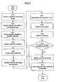
- Fig. 5 is a flow diagram depicting a method of reading action stickers and performing actions on stored documents responsive to the action stickers, according to one embodiment of the second mode of the present invention.
- Fig. 6A is an example depicting an action sticker affixed to a coversheet of a collection, according to one embodiment of the second mode of the present invention.
- Fig. 6B is an example depicting several action stickers applied to a coversheet of a collection, according to one embodiment of the second mode of the present invention.
- a method and apparatus for using collection coversheets with check boxes is disclosed.
- the collection coversheet may use thumbnails to represent documents and optionally may have titles, which are unrelated to their filenames.
- a user selects one or more check boxes on a collection coversheet to identify, by location on the coversheet, target documents within a previously stored collection of documents.
- each selection can be accessible using unguessable, unique identifiers anywhere on the Internet.
- the check boxes also specify actions to be performed on the target documents.
- the coversheet is scanned and the check boxes are located and read to determine which have been marked.
- the specified actions are then performed on the target documents. If the specified actions change the organization or architecture of the document collection, an updated version of the collection may be generated and stored, and a new coversheet may be printed.
- the actions and document selection may be completed using a single sheet.
- the collections can contain other collections. That is, the document in a sub-collection can be printed or e-mailed using the coversheet of the containing collection.
- the selection of the check box may select a document contained in a sub-collection.
- file names are not used on the coversheet.
- the entire process can be performed at an MFP. That is, the collection can be created and printed out with check boxes, and then an action can be selected using a check box and put through the MFP.
- the first mode of the present invention also relates to apparatus for performing the operations herein.
- This apparatus may be specially constructed for the required purposes, or it may comprise a general-purpose computer selectively activated or reconfigured by a computer program stored in the computer.
- a computer program may be stored in a computer readable storage medium, such as, but is not limited to, any type of disk including floppy disks, optical disks, CD-ROMs, and magnetic-optical disks, read-only memories (ROMs), random access memories (RAMs), EPROMs, EEPROMs, magnetic or optical cards, or any type of media suitable for storing electronic instructions, and each coupled to a computer system bus.
- a machine-readable medium includes any mechanism for storing or transmitting information in a form readable by a machine (e.g., a computer).
- a machine-readable medium includes read only memory ("ROM”); random access memory (“RAM”); magnetic disk storage media; optical storage media; flash memory devices; electrical, optical, acoustical or other form of propagated signals (e.g., carrier waves, infrared signals, digital signals, etc.); etc.
- a collection coversheet identifies a collection and also includes representations of documents within the collection.
- a collection coversheet includes:
- collection coversheets Further description of collection coversheets, collection identifiers, and collection overviews can be found in related patent applications referenced above and are discussed in more detail below.
- the following description sets forth the first mode of the invention in terms of check boxes and other indication or selection areas on collection coversheets.
- the first mode of the invention can also be implemented using check boxes on other types of identifier sheets, document indexes, or media items that identify stored documents, and that such implementations would not depart from the essential characteristics of the first mode of the present invention.
- collection coversheet 101 is a piece of paper that includes machine-readable collection identifier 102 and collection overview area 501 containing thumbnail representations 503A-H of digital documents. Also included is action indication area 510 where actions may be specified and annotation area 502 where notes may be written.
- action indication area 510 where actions may be specified
- annotation area 502 where notes may be written.
- check boxes 501 1 , 503A 1 -503H 3 , and 515 are located on coversheet 101.
- Check boxes 503A 1 -503H 3 are printed on thumbnail representations 503A-H, respectively, which refers to one of the documents in the collection associated with coversheet 101.
- Thumbnail representation 503H includes three check boxes 503H 1 -503H 3 .
- Thumbnail 503H represents a sub-collection where each of check boxes 503H 1 -503H 3 corresponds to one of the documents (or collection of documents) in the sub-collection of 503H.
- Check box 501 1 appears on collection overview area 501, and check boxes 515 appear on action indication area.
- check boxes 503A 1 -503H 3 may be located anywhere in overview area 501 in close proximity to one of the thumbnail representations to ensure a user desiring an action to be performed to a particular document is able to determine the correct check box to mark their selection.
- each of check boxes 515 is located in close proximity to a printed word specifying an action to allow a user to select one or more actions to be performed on selected documents.
- the system of the first mode of the present invention is capable of recognizing selected, or marked, check boxes regardless of the marks made in them.
- the user may mark the check box by filling in the check box or putting another mark (e.g., a check mark) in the box.
- another mark e.g., a check mark
- if any of the checkboxes has a dark pixel it is considered marked.
- Check boxes 515 as shown in Fig. 3 are square shaped and are next to, or in close proximity to, a word indicating the desired action (e.g., "Print").
- a word indicating the desired action e.g., "Print”
- Other formats and shapes e.g., circles, ovals, etc.
- another form of indication may be circular or elliptical to provide a user an area to mark to specify an action.
- such an arrangement would signal to the MFP of the first mode of the present invention that the requested action should be performed on those documents that correspond to thumbnails located between the check boxes.
- check boxes 515 indicates that the user wishes to perform a grouping action and any of check boxes 503A-H marked would identify particular documents that the user wishes to group together as a sub-collection within the original collection represented by coversheet 101.
- the MFP interprets the marked check boxes and performs the grouping operation as requested.
- grouping and sub-collection organization is implemented as described in related cross-referenced patent applications.
- the grouping operation consists of creating a new collection, moving the two documents or media into the new collection by adding them to the new collection and deleting them from the old collection. The new collection is then added to the old collection in approximately the same location as the original files.
- Collection check box 503H 1 may be marked to select the collection. This is different than selecting all the documents in the collection. If the collection check box 501H 1 is checked and the action "print” is selected by the user, the coversheet 101 is printed. If the collection check box 503H 1 is selected and the operation "delete” is selected, the subcollection will be deleted from the main collection instead of deleting the individual documents contained in the subcollection.
- the user if the user has indicated that an action should be performed on an entire collection and when it is possible to perform that action on other collections contained within that collection, it would be beneficial to give the user the opportunity to perform that action on the entire hierarchy.
- the collection represents the root collection of a deep hierarchy of collections, the user may choose to limit the depth of the action so that it terminates before it reaches all of the documents.
- the maximum depth of an action could be indicated using the control panel of the MFP or "Depth" checkboxes could be provided in the paper user interface on the collection coversheet.
- locating marked check boxes is performed using morphological operations well known to those skilled in the art. More specifically, a program performing morphological operations takes an input image and a "kernel" that resembles the object that is being sought, namely a check box of a given size in this case and compares the kernel with the input image at every pixel. Every time the kernel at a given position in the image exactly matches the input image, it leaves a dark pixel in the output image. In other words, the output image has a dark pixel in every place a check box appears in the input image. Processing logic can search for pixels in the outcome image after comparison and produce a list of image coordinates where there are marked check boxes.
- processing logic can find the collection overview and will look in the corners of the targets or objects. Similarly, it can keep track of where the boxes are printed and look precisely for the boxes later.
- FIG. 1 there is shown a block diagram depicting one embodiment of a functional architecture of a system for reading marked check boxes and performing actions on stored documents responsive to the marked check boxes.
- FIG. 2 there is shown a flow diagram of one embodiment of a process for reading marked check boxes and performing actions on stored documents responsive to the marked check boxes.
- the process may be performed, for example, by the system depicted in Fig. 1, or by other functional components and systems.
- the order of the operations in the described embodiment is merely exemplary. One skilled in the art will recognize that the operations can be performed in an order other than what is depicted.
- check boxes is described herein in the context of a multifunction peripheral (MFP) 100 including scanner 104, a machine-readable code locator and reader 106, a marked check box locator 107, a document identifier and processor 113, and printer 115.
- Marked check box locator 107 may also include functionality for locating collection overview area 501 within collection coversheet 101; alternatively, such functionality may be provided in a separate component (not shown).
- MFP 100 may also contain other components, some of which may not be required for the operation of this first mode of the invention.
- MFP 100 may contain a network interface card (not shown), which can receive processing requests from the external network, a fax interface, media capture devices, a media capture port, and the like.
- Control interface 117 provides a mechanism by which the user can initiate, configure, monitor, and/or terminate MFP 100 operations, for example, to make copies, scan documents, and print faxes.
- interface 117 includes a keypad, display, touchscreen, or any combination thereof.
- the components shown in MFP 100 are functional components that may be implemented using any combination of hardware elements, software, or the like.
- the functionality of reader 106 and locator 107 may be implemented within a single hardware component and/or software module, or they may be broken out into separate functional components.
- the architecture shown in Fig. 1 is intended to illustrate the overall functionality of the first mode of the invention according to one embodiment, and is not intended to limit the scope of the claimed invention to any particular set of components.
- MFP 100 can access other forms of media through electronic data input peripherals (not shown) including, for example, magnetic media readers for magnetic media such as floppy disks, magnetic tape, fixes hard disks, removable hard disks, memory cards, and the like. Peripherals may also include optical media readers (not shown) for optical storage media such as CDs, DVDs, magneto-optical disks, and the like.
- MFP 100 is communicatively coupled to storage device 109, which may be a hard drive or other device capable of storing collections of digital documents, for example in database form. Storage device 109 may be at the same location as MFP 100, or it may be remotely located, connected for example via a network.
- collection coversheet 101 includes machine-readable collection identifier 102 and collection overview area 501 containing thumbnail representations 503A-H of digital documents.
- collection coversheet 101 may have an embedded RFID tag containing collection identifier 102.
- Check boxes are included on coversheet 101 and may be marked to point to one of thumbnails 503A-H, thus identifying a particular document as the target for an action specified by marking one or more of the check boxes in action selection area.
- MFP 100 receives 201 an image 105 of coversheet 101, for example by scanning coversheet 101 using scanner 104 according to techniques that are well known in the art. Alternatively, MFP 100 may use other input mechanisms known to persons of ordinary skill in the art to receive the image of coversheet 101 (processing block 201). For example, MFP 100 may receive the image via e-mail, fax, retrieval from previously stored coversheet 101 images, or the like.
- MFP 100 locates 202 collection identifier 102 within image 105 of coversheet 101, and reads the identifier 102 (processing block 203).
- processing blocks 202 and 203 are performed by passing image 105 or the physical page in the case of RFID to code locator and reader 106, which locates and reads collection identifier 102.
- Collection identifier 102 identifies the storage location of documents in the collection.
- identifier 102 is a URL or the like that identifies documents by location and filename.
- identifier 102 may identify documents within storage device 109.
- identifier 102 also identifies a map that associates documents with particular regions within collection overview 501.
- Code locator and reader 106 passes the read collection identifier 102 to document identifier and processor 113 as described in more detail below.
- MFP 100 locates 204 collection overview 501 within image 105 of coversheet 101, for example by determining the overall size and shape of overview 501.
- overview 501 is provided at a standard location within coversheet 101, or is color-coded or otherwise marked, so as to facilitate easier identification of overview 501.
- overview 501 can be at an arbitrary location and have arbitrary characteristics.
- marked check box locator 1076 component of MFP 100 performs processing block 204; in another embodiment, another component (not shown) of MFP 100 performs this operation.
- MFP 100 locates 205 check box(s) that have been marked on collection overview 501.
- marked check box locator 107 component of MFP 100 performs processing block 205.
- Processing block 205 may be performed in response to the user specifying, via control interface 117, that one or more marked check boxes are present.
- locator 107 may be configured to automatically attempt to locate marked check boxes whenever a coversheet 101 has been scanned by scanner 104.
- marked check boxes are recognized by check box locator 107.
- Alternative methods for locating objects in an image are known in the art or have been described in related co-pending applications.
- check box locator 107 Based on which of the check boxes have been marked in the action indication area of coversheet 101, check box locator 107 identifies 206 the desired action(s). In one embodiment, action sticker locator and reader 107 passes the action request 112 to document identifier and processor 113.
- MFP 101 also determines, based on which of the check boxes 503A 1 -503H 3 in overview 501 are marked, the desired target document(s) for the action.
- check box locator 107 determines the location of each marked check box 503A 1 -503H 3
- document identifier and processor 113 determines a target document by comparing the location of marked check box with known information about thumbnail 503 locations in overview 501.
- storage device 109 includes a map 110 corresponding to each collection; the map provides coordinates for thumbnails 503 within overview 501.
- two-dimensional coordinates within overview 501 identify (or map to) documents, based on the locations of thumbnails 503 for those documents.
- the map is implemented as a list of rectangles, one representing the entire collection overview 501, and other rectangles representing positions of document thumbnails 503 within the overview 501.
- Map 110 may be stored as a separate file, such as a Scalable Vector Graphics (SVG) file containing a description of collection overview 501 with identifiers that associate regions within the overview 501 with documents in the collection.
- SVG Scalable Vector Graphics
- map 110 may be stored as part of collection information 301.
- Document identifier and processor 113 uses collection identifier 102 (obtained from code locator and reader 106) to retrieve, from storage 109, map 110 indicating the correspondence of coordinates within collection overview 501 to collection documents. Based on the map and based on marked check box location information 111, document identifier and processor 113 determines a target document. If a marked check box is within a rectangle representing a document thumbnail 503, the corresponding document is deemed to be the target of the action. Alternatively, in such a situation where ambiguity exists as to whether a document is the target document, MFP 101 can do any of the following: prompt the user, via control interface 117, to specify whether the document is intended to be the target.
- processing blocks 205 and 206 are performed using known techniques of optical feature recognition.
- document identifier and processor 113 sorts the actions in an appropriate order (processing block 207). For example, if marked check boxes 103 in the action indication area indicate that one or more documents should be both printed and deleted, the print action should take place before the delete action.
- the default sort order is as follows: print, e-mail, fax, group, ungroup, delete.
- MFP 100 may alert the user to the presence of multiple actions on a document and request clarification (via control interface 117, for example) as to the intended order to carry out the actions.
- MFP 100 locates the correct routing information (such as an e-mail address or a fax number) indicating the desired destination for the document. Routing information can be included on or written in the action indication area 515, or some other predetermined area on coversheet 101, such as written in annotation area 502 of coversheet 101, so that it can be extracted via optical character recognition (OCR). For example, if a single e-mail address is written in action indication area 515 or on the line next to the e-mail action, all documents to be e-mailed can be sent to that e-mail address. Alternatively, MFP 100 can prompt the user to enter routing information via control interface 117.
- OCR optical character recognition
- routing information could be written on a second sheet of paper to be scanned or in a second image received by MFP 100.
- the operation of determining routing information can be performed by marked check box locator 107, or by document identifier and processor 113, or by another component of MFP 100.
- document identifier and processor 113 uses collection identifier 102 (obtained from code locator and reader 106) to retrieve, from storage 109 (processing block 208), the target document(s) 114 and performs the specified action(s) in the determined order (processing block 209). For some actions (such as delete), retrieval of the document(s) 114 is not required, and processing block 208 is not performed.
- document identifier and processor 113 first retrieves collection information 301 which includes or points to target document(s) 114, and then obtains target document(s) 114 accordingly.
- check boxes and their corresponding actions include:
- Document identifier and processor 113 determines 210 whether any of the performed actions cause changes to collection map 110 and overview 501. If so, document identifier and processor 113 modifies 211 collection map 110 and overview 501 accordingly to indicate locations of thumbnails 503A-H corresponding to new documents and sub-collections and to delete one or more thumbnails 503A-H for documents and sub-collections that have been removed.
- the updated collection info 301, map 110, and/or overview 501 are stored in storage device 109.
- the updated collection information 301 and map 110 are sent to coversheet generator 302 for generation of an updated coversheet 101A including a new overview 501, as described below.
- a default layout can be used for the arrangement of thumbnails 503A-H.
- the user may be given an opportunity to indicate a layout.
- Printer 115 may optionally (or automatically) print 212 a new collection coversheet 306 representing the collection, particularly if collection organization has been modified, or if check boxes have been marked.
- printing of a document in the collection can be requested by marking a print check box on a coversheet 101.
- Machine-readable code locator and reader 106 reads the collection identifier 102.
- Check box locator 107 locates and reads the marked print check box, passing marked check box location information 111 and a print action request 112 to document identifier and processor 113.
- Document identifier and processor 113 identifies the target document based on the marked check box location information 111 and on map 110 retrieved from storage 109.
- Document identifier and processor 113 retrieves document 114 from storage and passes it to printer 115.
- Printer 115 outputs printed document 116.
- a new version of the collection is created.
- an updated version of the collection is generated and stored in a new location within storage 109, and a new collection identifier 102 is generated that points to the new location.
- a new coversheet 101A is printed with the new collection identifier 102. In this manner, previous versions of collections are preserved.
- Map 110 and overview 501 are altered to reflect that the document has been deleted.
- the new collection can be a new version of the original collection. Such versioning techniques are described in detail in related cross-referenced applications.
- MFP 100 includes coversheet generator 302, either as a separate functional module or as a component of document identifier and processor 113 or some other component.
- Coversheet generator 302 is therefore an optional component that need not be included, and indeed is absent in some embodiments.
- coversheet generator 302 performs processing block 211 to receive updated collection info 301A from document identifier and processor 113, modify collection map 110, and generate an updated coversheet 101A to be sent to printer 115 to be output as printed coversheet 306.
- a collection coversheet is a paper that represents a collection and, in one embodiment, comprises a header, a string of text printed in a machine-readable format, a collection overview image, optionally, an area in which notes may be written, and optionally a human-readable version of the text encoded in the machine-readable code.
- the header contains printed information about the collection. This information may include the author of the collection, a list of zero, one or more people who will be notified if the collection is modified, time and date information about when the collection was last modified or when this coversheet was printed out, and an optional collection topic or subject.
- the machine-readable code contains an encoded version of a unique pointer to the collection on the collection server.
- this same pointer when presented in the human-readable form is similar to a uniform resource locator or URL used in the World Wide Web and is referred to herein as a collection identifier, distributed resource identifier, or DRI.
- a collection server uses these DRIs as unique collection pointers.
- DRIs are globally unique, difficult to guess, and can provide access to collections from anywhere on the Internet.
- the terms "collection identifier,” “distributed resource identifier,” and “DRI” will be used interchangeably and should be understood to mean the same thing - a unique identifier that points to a collection of media and documents stored on a collection server. Also, the identifier might be written in human-readable form or machine-readable form. Both printed forms represent the same identifier and point to the same collection even though they look unlike each other.
- the DRI used for a collection points to a directory that contains the collection of documents as well as information used to build the collection overview and some additional metadata. DRIs can also point directly to an individual file the same way that a URL can point to either a directory or a file.
- the DRI is often a directory reference rather than a reference to a particular file.
- the DRI can be a directory reference such as /usr/collection.
- the DRI can refer to a file that in turn leads to an identification of the constituent elements of a collection.
- the DRI can be a reference to a database that stores the collection.
- the text of the DRI 510 may comprise a string of characters that includes a random text component. This randomly (and thus, unguessable) generated text serves to prevent access to a collection because it is virtually impossible to guess.
- the example DRI "/root/usr/collection" assumes a single-machine architecture.
- the DRI can include a machine name component.
- a more accessible format such as the URL (universal resource locator) format for identifying World Wide Web (WWW) pages might be suitable.
- the DRI constitutes the path portion of the URL.
- the path portion uses the following naming format according to a particular embodiment of this aspect of the first mode of the present invention: .../-DDS-/ORIGIN/ ..., where
- a collection may be identified by the following URL: http://machine1.com/-msg-/machine2.com/2002/1022/298hy9y8h8#$30er#/1/
- the IP address of the machine is identified by "machine1.com.”
- the path portion refers to a collection stored in a repository named "-msg-.”
- the original copy of the collection i.e., its place of creation
- machine is located on a machine named "machine2.com.”
- machine1 contains a copy of the collection.
- collections are contained in directories, though other data storage conventions can be used; e.g., collections can be stored and managed in a database.
- the collection shown in the example above is stored in a directory called: "/2002/1022/298hy9y8h8#$30er#/1/.”
- the pathname portion "/2002/1022” represents a date; e.g., date of creation of the collection.
- the string "398hy9y8h8#$30er#” represents randomly generated text.
- the directory represented by the terminal pathname "/1/" refers to the first (initial, original, base, etc.) version of the collection.
- both the host machine (“machine1”) and the original machine (“machine2”) use the following directory structure and URL naming structure.
- the host machine has a directory called "-msg-” contained in its respective "root” directory for storing collections.
- the "-msg-” directory has a sub-directory called “machine2.com” which contains all the collections originating on “machine2.com.”
- a sub-directory is provided for each machine that can be an originator of a collection.
- Using a 2-D bar code representation of a DRI allows for automated access to the collection without requiring the user to manually enter the location. It can be appreciated of course that any machine-readable indicium can be used instead of a bar code system, including optical character recognition (OCR) of the human-readable DRI.
- OCR optical character recognition
- a new, empty collection can be created.
- a new non-empty collection can be created using available documents and media.
- Electronic media and paper documents can be added to existing collections.
- a collection can be printed. Collections can be added to or merged. Also, actions can be taken on individual media in a collection using notes or actions selected on the coversheet.
- scalable vector graphics files or SVG files are used to represent the collection overview.
- SVG files are a standard way of creating a visual representation on the World Wide Web and there are many viewers and tools for creating SVG.
- a collection preferably includes a specially name SVG file which can be used to construct an overview image for the coversheet or any display.
- the SVG file includes information for displaying the thumbnails of individual documents and media stored in the collection.
- Metadata about the individual files in the collection and their relationship to other files in the collection is stored preferably in an XML (extensible markup language) file.
- this information includes image width and height, links between images and their thumbnails and links between a document and an image representing that document.
- the exact format is unimportant as long as the collection server understands how to read and write the format.
- Additional information related to the collection as a whole can also be stored in the metadata file. This information might include the time at which the message was created, the subject of the message, the name of the author of the collection, and contact information such as email addresses, fax numbers, etc. belonging to those who should be notified when a collection is altered.
- the MFP contacts the collection server through a network to request a new collection identifier or DRI. It should be understood that it is possible for the MFP to request identifiers in advance so that if the collection server is busy or temporarily offline, the MFP can still create new collections.
- the MFP composes a coversheet.
- a header block is created including at least the date and time of the creation of the new collection.
- the DRI or identifier obtained from the collection server is added to the coversheet at the bottom in human-readable form and then encoded in an industry standard two-dimensional PDF417 type barcode in one embodiment and added to the upper right-hand corner of the coversheet.
- An SVG representing the overview is converted to image form and added to the appropriate place in the coversheet. Additional information might also be added as deemed appropriate.
- the composition of the coversheet described here is one possibility but anyone skilled in the art will recognize that there are many ways to lay out or compose a coversheet that are within the scope of this first mode of the invention.
- each collection identifier represents a single collection but collections can change over time.
- each time a collection changes the last path element in the DRI is modified. Those who have access to a single collection are thereby easily given access to all versions of that collection.
- the version name or final pathname of /0/ has a special significance and means the "latest" or "most recently created” version.
- pathname /1/ indicates the first version of the collection, /2/ represents the second version, etc.
- a new directory using the next integer is created.
- the next collection after /2/ would preferably be called /3/.
- the version number cannot be created by the MFP because multiple MFPs might generate a number at the same time and choose the same name. Instead, the MFPs create a collection and upload it to a temporary directory on the collection server and when everything is uploaded, the collection server moves it into place and assigns the final pathname.
- the user can be placed on an automatic document feeder. If the user has images or other documents in a memory card or some other media, the media can be placed in the appropriate reader.
- the user If the user wishes to create some electronic media at the time of the creation of the new collection, the user records audio, video, still images, or other electronic media using any of the microphone, a digital camera, video camera, or other media-capturing device may be used.
- Each DRI is associated with the page of the document or image in which it was found.
- the MFP can recognize that a page containing a DRI represents a collection. Putting a page with a DRI into any collection, new or existing, could be understood as a request to add that collection to the new collection. In other words, the page containing the DRI represents a request to add the collection pointed to by that DRI to the new collection. The overview image of that collection will be retrieved and added as a thumbnail to the new collection and the subject of that collection will be used as the title for the thumbnail.
- one or more new identification numbers are requested and received from the collection server. In one embodiment, only a single collection identifier is needed for a new collection.
- Each document or page that was found to contain a DRI in machine-readable form is replaced with an image representing the collection pointed to by that DRI.
- a thumbnail is created for each page or document or other media.
- the thumbnail is preferably a smaller version of the page that is similar in appearance but smaller in storage size and in number of pixels.
- a thumbnail is just a representation of the audio and could be a waveform or even a standard computer icon representing the audio.
- the audio could be displayed as a rectangle containing a waveform whose shape is based on the audio content and whose length corresponds to the duration of the audio recording.
- a video thumbnail could be a single frame or a small number of representative frames from the video composited into a single small image.
- All of the media and documents for the new collection are now added to the collection, which means that they are uploaded to the collection server and placed in the directory pointed to by the DRI of the new collection.
- There are many well-known protocols for uploading files to a server including FTP, SCP, HTTP PUT.
- the HTTP PUT protocol is used which allows the MFP to specify the location and contents of each media file as it is being uploaded.
- thumbnails representing the new media items are arranged in the collection overview.
- the thumbnails are placed in an appropriate manner within the overview, expanding the overview size if necessary.
- the SVG file representing the overview is written and uploaded to the collection server and all of the thumbnails are uploaded.
- One method for placing thumbnails is to find a place in the overview image where the thumbnail can be positioned where it will not overlap any other thumbnail.
- An exhaustive search - moving the thumbnail to different positions within the overview and looking for overlaps with other thumbnails - is too slow.
- Another approach is to reduce the problem to that of placing a single point. This can be done by reducing the size of the overview by the width and height of the thumbnail to be placed and enlarging the existing thumbnails by the same dimensions.
- the origin of the new thumbnail can be placed anywhere within the remaining space in the overview without overlapping existing thumbnails.
- thumbnail size is determined. Thumbnail sizes are usually measured in pixels. Often thumbnails are chosen to be some standard size - chosen so that they neither the width nor height is larger than a certain maximum size - perhaps 150 pixels for standard display resolutions or two inches for printed thumbnails. Since some images might have a very large or very small aspect ratio. It might be more appropriate to limit the thumbnail to a maximum area - square pixels or square inches - rather than a maximum width and height.
- Scaling an image so that it contains no more than some total number of pixels instead of restricting the width and height to be less than some maximum improves the overall appearance of the thumbnails and is the preferred method of selecting a thumbnail size.
- any method for choosing thumbnail sizes can be used for the first mode of the present invention.
- a single bounding box for all the thumbnails previously placed on the overview is calculated and the origin of the new thumbnail is placed outside of that bounding box. It is also possible and understood by extension that instead of calculating just a single bounding box, an individual bounding box for each thumbnail may be calculated and extended so that the new thumbnail can be placed in any available position in the overview. This is well understood by those experienced with path planning algorithms and would be analogous to allowing a machine to travel between obstacles instead of requiring the robot to go around all the obstacles.
- Adding a second new thumbnail now to the overview could be accomplished. However, instead of adding one bounding box to cover all the thumbnails, simply adding a single box representative of the newly added thumbnail is the preferred approach. This box is calculated to be the size of the newly added thumbnail and then is extended up and to the left by the width and height of the thumbnail to be added, just like the first bounding box.
- All modified information is sent to the collection server, including the metadata files, SVG overview file, and any changes in the collection.
- the user may bring media to the MFP or creates it using media recording devices or the like connected to the MFP or to the network.
- the advantage of having a machine-readable collection identifier on a coversheet is that the MFP or any device that can locate and decode machine-readable codes can determine which collection is represented by the coversheet.
- the user can indicate which collection the new media will be added to by typing in a collection identifier or DRI but this can be a difficult task because DRIs tend to be long random strings of characters.
- DRI's can be located and decoded from a scanned image or read using handheld barcode scanners if they are encoded in barcode format.
- Handheld scanners which read many different types of one and two-dimensional barcodes are available from many companies like Hewlett-Packard Company of Palo Alto, California, USA.
- the coversheet should be placed on the MFP where it can be scanned, either in the automatic document feeder or directly on the glass platen.
- the barcode can be scanned using a handheld scanner. If the barcode has been captured in a digital image, perhaps using a digital camera, the camera can be directly connected to the MFP or a memory card from the camera can be plugged into a card reader.
- a machine-readable DRI is presented as part of the coversheet of the collection.
- the DRI is contained in PDF417 format two-dimensional barcode on the coversheet and the coversheet is placed on an automatic document feeder (ADF) of the MFP.
- ADF automatic document feeder
- Additional documents or pages to be added to the collection are placed behind the coversheet.
- the additional pages can be any document pages or they can be coversheets of other messages.
- Each of the documents and media is searched for a machine-readable DRI.
- the DRI can be stored in the memory of the MFP so that it can be accessed when it is time to determine which collection to add the new media to. If the ADF or a platen has been used to scan in a coversheet or if the DRI is contained in an image from the digital camera, the DRI will have to be read from the scanned r captured image. Either source of a DRI is acceptable and typically, if there is no DRI held in a memory due to hand scanning of a coversheet, the first scanned sheet or first image will contain the DRI. Those skilled in the art will recognize that there are many ways of providing the DRI to the MFP an exhaustive list need not be provided.
- the entire image media including images that are scans of document pages is searched for machine-readable codes.
- the image of that page is added to the collection storage area and a thumbnail is added to the overview. If that page happens to contain a machine-readable DRI then based on the users preference, instead of adding the page to the collection, the collection that the DRI represents can be added to the collection.
- the "page add" request is converted into a "collection add” request with the appropriate DRI representing the collection.
- Thumbnails are created for all of the new images, documents, pages, and media. For those pages that represent other collections, thumbnails are made for the collections instead of the page. All collected media is uploaded to the collection server.
- new media and thumbnails in a collection are uploaded to a staging area on the collection server.
- the staging area is associated with the collection identifier but doesn't have a permanent final pathname.
- the collection server moves the collection into a final directory or storage area with a permanent final pathname.
- the permanent final pathname is usually the next integer after the most recently uploaded collection.
- the thumbnails representing the new media are added to the collection overview.
- thumbnails, metadata, and the overview SVG file are uploaded to the staging area in the collection server. All changes and modifications are finally uploaded to the collection server and at this point, the server has everything required to move the collection out of the staging area and into the final directory upon assigning a version number.
- a collection server can keep a mapping of collection identifiers to collection directories.
- the second mode of the present invention is described more fully with reference to the accompanying Figures, in which several embodiments of the second mode of the present invention are shown.
- the second mode of the present invention may be embodied in many different forms and should not be construed as limited to the embodiments set forth herein. Rather these embodiments are provided so that this disclosure will be complete and will fully convey the second mode of the invention to those skilled in the art.
- the second mode of present invention also relates to an apparatus for performing the operations herein.
- This apparatus may be specially constructed for the required purposes, or it may comprise a general-purpose computer selectively activated or reconfigured by a computer program stored in the computer.
- a computer program may be stored in a computer readable storage medium, such as, but is not limited to, any type of disk including floppy disks, optical disks, CD-ROMs, and magnetic-optical disks, read-only memories (ROMs), random access memories (RAMs), EPROMs, EEPROMs, magnetic or optical cards, or any type of media suitable for storing electronic instructions, and each coupled to a computer system bus.
- a component of the second mode of the present invention is implemented as software
- the component can be implemented as a standalone program, as part of a larger program, as a plurality of separate programs, as a statically or dynamically linked library, as a kernel loadable module, as a device driver, and/or in every and any other way known now or in the future to those of skill in the art of computer programming.
- the second mode of the present invention is in no way limited to implementation in any specific operating system or environment.
- a collection coversheet identifies a collection and also includes representations of documents within the collection.
- a collection coversheet includes:
- collection coversheets Further description of collection coversheets, collection identifiers, and collection overviews can be found in related patent applications referenced above and incorporated herein by reference.
- the second mode of the invention in terms of action stickers on collection coversheets.
- the second mode of the invention can also be implemented using action stickers on other types of identifier sheets, document indexes, or media items that identify stored documents, and that such implementations would not depart from the essential characteristics of the second mode of the present invention.
- collection coversheet 1101 is a piece of paper that includes machine-readable collection identifier 1102 and collection overview area 1501 containing thumbnail representations 1503A-F of digital documents (though other representation of documents can be used in lieu of thumbnails 1503A-F, such as for example a simple text list of documents). Also included is annotation area 1502, where notes may be written, as described in related cross-referenced applications.
- the particular layout and components shown in Fig. 6A are merely exemplary.
- a print action sticker 1103A has been affixed to coversheet 1101. It overlaps and points toward thumbnail representation 1503A, which refers to one of the documents in the collection associated with coversheet 1101.
- action stickers 1103 may be placed in any orientation in overview area 1501.
- the system of the second mode of the present invention is capable of recognizing action stickers 1103 regardless of their orientations.
- action stickers 1103 are removable, reusable, and recyclable. They may employ a weak adhesive similar to that found in commonly used removable office notes such as Post-It® Notes available from 3M Company of St. Paul, Minnesota.
- One benefit of removable action stickers is that collection coversheet 1101 is not permanently marred or ruined by the application of action stickers 1103; thus, the user need not reprint new copies of coversheet 1101 to execute each document processing request.
- Reusable action stickers 1103 reduce the amount of waste generated by the second mode of the invention, and reduce the cost to the consumer of implementing the second mode of the invention. Making action stickers out of recyclable material allows for a coversheet with stickers to be recycled according to conventional recycling methods, without having to separate the stickers from the coversheet 1101.
- the second mode of the invention can be implemented using action stickers 1103 having other forms and characteristics; for example, non-removable and/or non-recyclable action stickers 1103 may be used without departing from the essential characteristics of the second mode of the invention.
- Action sticker 1103A as shown in Fig. 6A is arrow-shaped and includes a word indicating the desired action ("Print").
- a word indicating the desired action (“Print").
- an action sticker 1103 may specify an action based on its shape and/or color, or on its orientation or position as placed on coversheet 1101, or on a symbol, icon, letter, word, or machine-readable code printed on sticker 1103.
- the action sticker 1103 is machine-readable, so that the shape, color, word, icon, symbol, letter, word, or code is understandable by a machine.
- an action sticker 1103 in the shape of a small "L" that can be used to identify a group of one or more documents on which an action is to be performed.
- Two stickers 1103 can be affixed to delimit the group of documents, by placing a first sticker 1103 at the top left corner of the thumbnail of the first document to be processed and a second sticker 1103 at the bottom right corner of the thumbnail of the last document in the group.
- such an arrangement would signal to the MFP of the second mode of the present invention that the requested action should be performed those documents that correspond to thumbnails located between the action stickers 1103.
- Other formats for action stickers 1103, such as dots, brackets, and rectangles may also be used without departing from the principles of the second mode of the invention.
- action stickers 1103 are of relatively small size as compared to overview area 1501, so as to facilitate more accurate interpretations of which document is the intended target based on the placement of the action sticker 1103. If an action sticker 1103 is placed such that it overlaps more than one thumbnail 1503, for example, there is potential ambiguity as to which document should be processed. As will be described in more detail below, the MFP of the second mode of the present invention can employ any of a number of techniques to resolve such ambiguity. At any rate, an action sticker 1103 of relatively small size is less likely to overlap two or more thumbnails.
- FIG. 6B there is shown an example wherein multiple action stickers 1103B-D have been affixed to collection coversheet 1101, according to one embodiment of the second mode of the present invention.
- "Group" action stickers 1103B-D are shown by way of example.
- Group action stickers 1103B-D identify particular documents (in this case, those documents corresponding to thumbnails 1503A, 1503F, and 1503E), that the user wishes to group together as a sub-collection within the original collection represented by coversheet 1101.
- MFP interprets stickers 1103B-D and performs the grouping operation as requested.
- grouping and sub-collection organization is implemented as described in related cross-referenced patent applications that have been incorporated herein by reference.
- FIG. 4 there is shown a block diagram depicting a functional architecture of a system for reading action stickers and performing actions on stored documents responsive to the action stickers, according to one embodiment of the second mode of the present invention.
- FIG. 5 there is shown a flow diagram depicting a method of reading action stickers and performing actions on stored documents responsive to the action stickers, according to one embodiment of the second mode of the present invention.
- the method may be performed, for example, by the system depicted in Fig. 4, or by other functional components and systems.
- the order of the steps in the described embodiment is merely exemplary. One skilled in the art will recognize that the steps can be performed in an order other than what is depicted.
- MFP multifunction peripheral
- scanner 1104 a machine-readable code locator and reader 1106, an action sticker locator and reader 1107, a document identifier and processor 1113, and printer 1115.
- Action sticker locator and reader 1107 may also include functionality for locating collection overview area 1501 within collection coversheet 1101; alternatively, such functionality may be provided in a separate component (not shown).
- MFP 1100 may also contain other components, some of which may not be required for the operation of this second mode of the invention.
- MFP 1100 may contain a network interface card (not shown), which can receive processing requests from the external network, a fax interface, media capture devices, a media capture port, and the like.
- Control interface 1117 provides a mechanism by which the user can initiate, configure, monitor, and/or terminate MFP 1100 operations, for example, to make copies, scan documents, and print faxes.
- interface 1117 includes a keypad, display, touchscreen, or any combination thereof.
- MFP 1100 The components shown in MFP 1100 are functional components that may be implemented using any combination of hardware elements, software, or the like.
- reader 1106 and reader 1107 may be implemented within a single hardware component and/or software module, or they may be broken out into separate functional components.
- the architecture shown in Fig. 4 is intended to illustrate the overall functionality of the second mode of the invention according to one embodiment, and is not intended to limit the scope of the claimed invention to any particular set of components.
- MFP 1100 can access other forms of media through electronic data input peripherals (not shown) including, for example, magnetic media readers for magnetic media such as floppy disks, magnetic tape, fixed hard disks, removable hard disks, memory cards, and the like. Peripherals may also include optical media readers (not shown) for optical storage media such as CDs, DVDs, magneto-optical disks, and the like.
- MFP 1100 is communicatively coupled to storage device 1109, which may be a hard drive or other device capable of storing collections of digital documents, for example in database form. Storage device 1109 may be at the same location as MFP 1100, or it may be remotely located, connected for example via a network.
- collection coversheet 1101 includes machine-readable collection identifier 1102 and collection overview area 1501 containing thumbnail representations 1503 of digital documents.
- Action sticker 1103 is affixed to coversheet 1101 in such a way that it points to thumbnail 1503, thus identifying a particular document as the target for the specified action.
- MFP 1100 receives 1201 an image 1105 of coversheet 1101, for example by scanning coversheet 1101 using scanner 1104 according to techniques that are well known in the art. Alternatively, MFP 1100 may use other input mechanisms known to persons of ordinary skill in the art to receive 1201 the image of coversheet 1101. For example, MFP 1100 may receive the image via e-mail, fax, retrieval from previously stored coversheet 1101 images, or the like.
- MFP 1100 locates 1202 collection identifier 1102 within image 1105 of coversheet 1101, and reads 1203 the identifier 1102.
- steps 1202 and 1203 are performed by passing image 1105 to machine-readable code locator and reader 1106, which locates and reads collection identifier 1102.
- Collection identifier 1102 identifies the storage location of documents in the collection.
- identifier 1102 is a URL or the like that identifies documents by location and filename.
- identifier 1102 may identify documents within storage device 1109.
- identifier 1102 also identifies a map that associates documents with particular regions within collection overview 1501.
- Code locator and reader 1106 passes the read collection identifier 1102 to document identifier and processor 1113 as described in more detail below.
- MFP 1100 locates 1204 collection overview 1501 within image 1105 of coversheet 1101, for example by determining the overall size and shape of overview 1501.
- overview 1501 is provided at a standard location within coversheet 1101, or is color coded or otherwise marked, so as to facilitate easier identification of overview 1501.
- overview 1501 can be at an arbitrary location and have arbitrary characteristics.
- action sticker locator and reader 1107 component of MFP 1100 performs step 1204; in another embodiment, another component (not shown) of MFP 1100 performs this step.
- MFP 1100 locates 1205 action sticker(s) 1103 that have been affixed to collection overview 1105.
- action sticker locator and reader 1107 component of MFP 1100 performs step 1205.
- Step 1205 may be performed in response to the user specifying, via control interface 1117, that one or more action sticker(s) 1103 are present.
- reader 1107 may be configured to automatically attempt to locate action sticker(s) 1103 whenever a coversheet 1101 has been scanned by scanner 1104.
- action stickers are recognizable in some way to action sticker locator and reader 1107, such as by being a unique color, containing a barcode, having a specific and recognizable shape, or by some other visual characteristic.
- Alternative methods for locating objects in an image are known the art or have been described in related co-pending applications.
- action sticker locator and reader 1107 Based on visual characteristic of action sticker(s) 1103, action sticker locator and reader 1107 identifies 1206 the desired action(s).
- stickers 1103 corresponding to a particular action are visually similar in some respect, for example having the same color or having the same word printed on them.
- stickers 1103 corresponding to different actions may be visually dissimilar in some respect, for example by being different colors or having a different word printed on them.
- action sticker locator and reader 1107 passes the action request 1112 to document identifier and processor 1113.
- MFP 1101 also determines, based on the location of action sticker(s) 1103, the desired target document(s) for each action. In one embodiment, this determination is made by a) determining an action point for each action sticker 1103, and b) determining which thumbnail 1503 is located at, or closest to, the action point. In one embodiment, action sticker locator and reader 1107 determines action points for each sticker 1103, and document identifier and processor 1113 determines a target document by comparing the location of action points with known information about thumbnail 1503 locations in overview 1501.
- the action point for a sticker 1103 can be the tip of an arrow, or the center of a target, or some other location on the sticker 1103 that indicates a target document.
- action sticker locator and reader 1107 passes sticker location information 1111 to document identifier and processor 1113; this sticker location information 1111 can include action point coordinates. If action sticker locator and reader 1107 determines that the action point for a sticker is outside collection overview area 1501, in one embodiment it ignores the sticker 1103 and does not pass the information 1111 to document identifier and processor 1113. In another embodiment, it still passes the information 1111, so that document identifier and processor 1113 can attempt a best estimate as to the target document.
- storage device 1109 includes a map 1110 corresponding to each collection; the map provides coordinates for thumbnails 1503 within overview 1501.
- two-dimensional coordinates within overview 1501 identify (or map to) documents, based on the locations of thumbnails 1503 for those documents.
- the map is implemented as a list of rectangles, one representing the entire collection overview 1501, and other rectangles representing positions of document thumbnails 1503 within the overview 1501.
- Map 1110 may be stored as a separate file, such as a Scalable Vector Graphics (SVG) file containing a description of collection overview 1501 with identifiers that associate regions within the overview 1501 with documents in the collection.
- SVG Scalable Vector Graphics
- map 1110 may be stored as part of collection information 1301.
- Document identifier and processor 1113 uses collection identifier 1102 (obtained from code locator and reader 1106) to retrieve, from storage 1109, map 1110 indicating the correspondence of coordinates within collection overview 1501 to collection documents. Based on the map and based on sticker location information 1111, document identifier and processor 1113 determines a target document. If an action point falls within a rectangle representing a document thumbnail 1503, the corresponding document is deemed to be the target of the action. If the action point falls within the rectangles of more than one thumbnail 1503 (in an implementation where document thumbnails 1503 can overlap), the action can be performed on both documents, or just the topmost document or the first document.
- MFP 1101 can do any of the following: designate as the target the document corresponding to the closest thumbnail 1503 to the action point; determine which document is most likely the intended target based on the type of action being performed and the type of document; determine which document is most likely the intended target based on historical usage; display an error message; and/or prompt the user, via control interface 1117, to specify which document is intended to be the target.
- document identifier and processor 1113 can determine the intended target based on: a) which thumbnail 1503 is closest to the action point; b) which thumbnail 1503 is pointed to by the action sticker 1113; c) which document is best suited for the particular action; d) historical usage; or e) additional information form the user, provided in response to a prompt via control interface 1117.
- sticker 1103 is arrow-shaped
- document identifier and processor 1113 is configured to recognize that the likely intended target document is the one that is pointed to by the arrow. Thus, in situations where the action point of sticker 1103 falls between rectangles, document identifier and processor 1113 (or action sticker locator and reader 1107) determines which way the arrow is pointing, so as to more accurately determine the target document.
- coordinates for the action point and overall coordinates for the collection overview 1501 are normalized.
- coordinates of the action point are converted from a location on coversheet 1101 to a location within the overview 1501.
- steps 1205 and 1206 are performed using known techniques of optical feature recognition.
- document identifier and processor 1113 sorts 1207 the actions in an appropriate order. For example, if stickers 1103 for a particular target document indicate that the document should be both printed and deleted, the print action should take place before the delete action.
- the default sort order is as follows: print, e-mail, fax, group, ungroup, delete.
- MFP 1100 may alert the user to the presence of multiple actions on a document and request clarification (via control interface 1117, for example) as to the intended order to carry out the actions.
- MFP 1100 locates the correct routing information (such as an e-mail address or a fax number) indicating the desired destination for the document. Routing information can be included on or written on sticker 1103, or written in annotation area 1502 of coversheet 1101, so that it can be extracted via optical character recognition (OCR). For example, if a single e-mail address is written in annotation area 1502, all documents to be e-mailed can be sent to that e-mail address. Alternatively, MFP 1100 can prompt the user to enter routing information via control interface 1117. Alternatively, the routing information could be written on a second sheet of paper to be scanned or in a second image received by MFP 1100. In any of these embodiments, the operation of determining routing information can be performed by action sticker locator and reader 1107, or by document identifier and processor 1113, or by another component of MFP 1100.
- OCR optical character recognition
- document identifier and processor 1113 uses collection identifier 1102 (obtained from code locator and reader 1106) to retrieve 1208, from storage 1109, the target document(s) 1114 and performs 1209 the specified action(s) in the determined order. For some actions (such as delete), retrieval of the document(s) 1114 is not required, and step 1208 is not performed. In one embodiment, document identifier and processor 1113 first retrieves collection information 1301 which includes or points to target document(s) 1114, and then obtains target document(s) 1114 accordingly.
- Examples of stickers 1103 and their corresponding actions include:
- Document identifier and processor 1113 determines 1210 whether any of the performed actions cause changes to collection map 1110 and overview 1501. If so, document identifier and processor 1113 modifies 1211 collection map 1110 and overview 1501 accordingly to indicate locations of thumbnails 1503 corresponding to new documents and sub-collections and to delete thumbnails 1503 for documents and sub-collections that have been removed.
- the updated collection info 1301, map 1110, and/or overview 1501 are stored in storage device 1109.
- the updated collection information 1301 and map 1110 are sent to coversheet generator 1302 for generation of an updated coversheet 1101A including a new overview 1501, as described below.
- Printer 1115 may optionally (or automatically) print 1212 a new collection coversheet 1306 representing the collection, particularly if collection organization has been modified, or if nonremovable stickers 1103 have been used.
- a print action sticker 1103 can be used to request printing of a document in the collection by placing print action sticker 1103 on coversheet 1101.
- Machine-readable code locator and reader 1106 reads the collection identifier 1102.
- Action sticker locator and reader 1107 locates and reads the print action sticker 1103, passing sticker location information 1111 and a print action request 1112 to document identifier and processor 1113.
- Document identifier and processor 1113 identifies the target document based on the sticker location information 1111 and on map 1110 retrieved from storage 1109.
- Document identifier and processor 1113 retrieves document 1114 from storage and passes it to printer 1115.
- Printer 1115 outputs printed document 1116.
- a new version or layer of the collection is added.
- an updated version of the collection is generated and stored in a new location within storage 1109, and a new collection identifier 1102 is generated that points to the new location.
- a new coversheet 1101A is printed with the new collection identifier 1102. In this manner, previous versions of collections are preserved.
- Map 1110 and overview 1501 are altered to reflect that the document has been deleted.
- the new collection can be either a new layer of the original collection or it can be a completely new collection unrelated to the original except that it was derived from the original. Such versioning and layering techniques are described in detail in related cross-referenced applications.
- MFP 1100 includes coversheet generator 1302, either as a separate functional module or as a component of document identifier and processor 1113 or some other component.
- Coversheet generator 1302 is therefore an optional component that need not be included, and indeed is absent in some embodiments.
- coversheet generator 1302 performs step 1211 to receive updated collection info 1301A from document identifier and processor 1113, modify collection map 1110, and generate an updated coversheet 1101A to be sent to printer 1115 to be output as printed coversheet 1306.
- the second mode of the present invention includes the following additional features and functionality. Any of these features may be included alone or in combination with one another and/or in combination with the above-described features and components.
- action stickers 1103 are used to specify or modify access permission levels to documents and/or to create a collection with limited access permissions for documents in the collection. Upon detecting such an action sticker 1103, MFP 1100 modifies access permission levels according to techniques that are described in related cross-referenced patent applications.
- Action Stickers as Physical Access Keys.
- action stickers 1103 contain machine-readable codes containing keys to decrypt encrypted documents stored in collections.
- the action sticker 1103 functions as a physical access key as described in related cross-referenced application No. titled "Physical Key for Accessing a Securely Stored Digital Document," filed August 11, 2003 and incorporated herein by reference.
- coversheet 1101 the action sticker 1103 identifies which document or collection should be decrypted using the decryption key imprinted on the action sticker 1103.
- Generic Action Stickers can be applied to collection coversheets 1101.
- Generic action stickers are identifiable by some visual characteristic as being an action sticker 1103, but one without a particular action.
- one format for generic action stickers is to be the same size and shape as other action stickers 1103, but without any words printed on them.
- coversheet 1101 By its placement on coversheet 1101, a generic action sticker identifies one or more target document(s) but does not identify an action to be performed. The user is prompted, for example via control interface 1117, to specify a desired action to be performed on the target document(s).
Landscapes
- Engineering & Computer Science (AREA)
- Multimedia (AREA)
- Signal Processing (AREA)
- Computer Vision & Pattern Recognition (AREA)
- Databases & Information Systems (AREA)
- Theoretical Computer Science (AREA)
- Business, Economics & Management (AREA)
- Data Mining & Analysis (AREA)
- Physics & Mathematics (AREA)
- General Engineering & Computer Science (AREA)
- General Physics & Mathematics (AREA)
- General Business, Economics & Management (AREA)
- Automation & Control Theory (AREA)
- Library & Information Science (AREA)
- Facsimiles In General (AREA)
- Editing Of Facsimile Originals (AREA)
- Storing Facsimile Image Data (AREA)
Abstract
Description
- U.S. Patent Application No. 10/404, 927 entitled "MULTIMEDIA DOCUMENT SHARING METHOD AND APPARATUS," filed March 31, 2003;
- U.S. Patent Application No. 09/521, 252 entitled "METHOD AND SYSTEM FOR INFORMATION MANAGEMENT TO FACILITATE THE EXCHANGE OF IDEAS DURING A COLLABORATIVE EFFORT," filed March 8, 2000;
- U.S. Patent Application No. 10/001,895 entitled "PAPER-BASED INTERFACE FOR MULTIMEDIA INFORMATION," filed November 19, 2001;
- U.S. Patent Application No. 10/081,129 entitled "MULTIMEDIA VISUALIZATION & INTEGRATION ENVIRONMENT," filed February 21, 2002;
- U.S. Patent Application No. 10/085,569 entitled "A DOCUMENT DISTRIBUTION AND STORAGE SYSTEM," file February 26, 2002;
- U.S. Patent Application No. 10/174,522 entitled "TELEVISION-BASED VISUALIZATION AND NAVIGATION INTERFACE," filed June 17, 2002;
- U.S. Patent Application No. 10/175,540 entitled "DEVICE FOR GENERATING A MULTIMEDIA PAPER DOCUMENT," filed June 18, 2002;
- U.S. Patent Application No. 10/307,235 entitled "MULTIMODAL ACCESS OF MEETING RECORDINGS," filed November 29, 2002; and
- U.S. Patent Application No. entitled "PHYSICAL KEY FOR ACCESSING A SECURELY STORED DIGITAL DOCUMENT," filed August 11, 2003.
- A collection identifier in machine-readable form (such as a barcode) and/or human-readable form (such as a Uniform Resource Locator (URL) or other text string). The collection identifier provides information describing a location of the collection, such as a directory or folder containing documents in the collection.
- A collection overview, which represents documents in the collection by thumbnails. Thumbnails are associated with positions in the overview. For instance, the thumbnail for document A might be in the upper left corner of the collection overview, and the thumbnail for document B might be in the lower right corner.
.../-DDS-/ORIGIN/ ...,
where
http://machine1.com/-msg-/machine2.com/2002/1022/298hy9y8h8#$30er#/1/
"/2002/1022/298hy9y8h8#$30er#/1/."
The pathname portion "/2002/1022" represents a date; e.g., date of creation of the collection. The string "398hy9y8h8#$30er#" represents randomly generated text. Finally, as will be discussed below, the directory represented by the terminal pathname "/1/" refers to the first (initial, original, base, etc.) version of the collection.
- A collection identifier in machine-readable form (such as a barcode) and/or human-readable form (such as a Uniform Resource Locator (URL) or other text string). The collection identifier provides information describing a location of the collection, such as a directory or folder containing documents in the collection.
- A collection overview, which represents documents in the collection by thumbnails. Thumbnails are associated with positions in the overview. For instance, the thumbnail for document A might be in the upper left corner of the collection overview, and the thumbnail for document B might be in the lower right corner.
Claims (44)
- A computer-implemented method comprising:receiving an image of an overview of a collection;identifying at least one action set forth in the image;identifying at least one document; andperforming the at least one action on the at least one document.
- The method defined in Claim 1 wherein identifying the at least one document comprises:identifying a location on the image of at least one indication area having a mark therein, the at least one indication area being associated with the at least one document; andidentifying the at least one document based on the location of the at least one indication area having the mark therein.
- The method defined in Claim 2 wherein the at least one indication area comprises one of a plurality of check boxes in the image, wherein each of the plurality of check boxes is associated with one of a plurality of graphics in the image, wherein each of the plurality of graphics is associated with one or more documents.
- The method of claim 2, wherein the collection overview comprises a plurality of representations of documents, and wherein identifying at least one document based on the location of the at least one indication area comprises identifying the at least one document corresponding to a document representation indicated by the mark in the at least one indication area.
- The method of claim 2, wherein the collection overview comprises a plurality of representations of documents; and further
wherein identifying the at least one document based on the location of the at least one indication area having the mark therein comprises:determining a coordinate location for the at least one indication area having the mark therein;determining a coordinate location for at least one of the document representations; andidentifying a first document by comparing the coordinate location for at least one indication area having the mark therein with the coordinate location for the at least one document representation. - The method defined in Claim 1 wherein receiving an image of an overview of the collection comprises capturing an image of the sheet and identifying at least one document by reading an RFID tag embedded in the sheet, the data on the RFID tag identifying the collection containing a document.
- The method defined in Claim 1 further comprising scanning a sheet having an identifier and having graphical content representing a collection of one or more media objects, wherein scanning the sheet results in creating the image.
- The method defined in Claim 1 wherein the plurality of actions comprise two or more of a group consisting of printing, faxing, sending by electronic mail, deleting, grouping, ungrouping, and playing.
- The method defined in Claim 1 wherein identifying at least one action set forth in the image comprises identifying a location of a mark in an action indication area on the image.
- The method defined in Claim 1 wherein the at least one documents comprises a collection of documents.
- The method defined in Claim 1 wherein the at least one document is part of a stored collection, and further wherein the collection overview comprises a collection coversheet.
- The method of claim 11, wherein the collection coversheet comprises a machine-readable collection identifier specifying a storage location for the collection, the method further comprising, prior to performing at least one action, retrieving the at least one document from the storage location.
- The method of claim 1, wherein the at least one action specifies a grouping action, and wherein the at least one document comprises two or more documents, and wherein performing the at least one action comprises grouping the two or more documents.
- The method of claim 1, wherein the at least one action comprises transmitting the at least one document to a destination, the method further comprising determining a destination.
- The method of claim 1, further comprising, prior to performing the at least one action, retrieving the at least one document from a storage device.
- A computer-implemented method comprising:receiving an image of an overview of a collection and a machine readable pointer identifying the collection;locating, on the document index image, at least two marked check boxes;identifying a document for at least one of the marked check boxes based on location of the at least one of marked check boxes on the document index page;identifying an action from the document index page; andperforming the action on the documents identified for each of the marked check boxes.
- An article of manufacture comprising one or more recordable media having instructions stored thereon which, when executed by a computer, cause the computer to perform a method comprising:receiving an image of an overview of a collection;identifying at least one action set forth in the image;identifying at least one document; andperforming the at least one action on the at least one document.
- The article of manufacture defined in claim 17 wherein identifying the at least one document comprises:identifying a location on the document index image of at least one indication area having a mark therein, the at least one indication area being associated with the at least one document; andidentifying the at least one document based on the location of the at least one indication area having the mark therein.
- The article of manufacture defined in Claim 18 wherein the at least one indication area comprises one of a plurality of check boxes in the image, wherein each of the plurality of check boxes is associated with one of a plurality of graphics in the image, wherein each of the plurality of graphics is associated with one or more documents.
- The article of manufacture defined in Claim 17 wherein the indication area is located on top of a portion of a graphic representing at least one document in a collection.
- The article of manufacture defined in Claim 17 wherein the method further comprises scanning a sheet having an identifier and having graphical content representing a collection of one or more media objects,
wherein scanning the sheet results in creating the image. - The article of manufacture defined in Claim 17 wherein the plurality of actions comprise two or more of a group consisting of printing, faxing, sending by electronic mail, deleting, grouping, ungrouping, and playing.
- The article of manufacture defined in Claim 17 wherein identifying at least one action set forth in the image comprises identifying a location of a mark in an action indication area on the image.
- The article of manufacture defined in Claim 17 wherein the at least one document is part of a stored collection, and further wherein collection overview comprises a collection coversheet.
- The article of manufacture of claim 24, wherein the collection coversheet comprises a machine-readable collection identifier specifying a storage location for the collection, the method further comprising, prior to performing at least one action, retrieving the at least one document from the storage location.
- The article of manufacture of claim 17, wherein the at least one action comprises transmitting the at least one document to a destination, the method further comprising determining a destination.
- The article of manufacture of claim 17, wherein the document index comprises an identifier specifying a storage location, and the method further comprising, prior to performing the at least one action, retrieving the at least one document from the storage location.
- A system for processing a stored document, comprising:a document index input device, to receive an image of a document index;a marked check box locator, coupled to the document input index device, to identify at least one action set forth in the image and to identify a location on the document index image of at least one indication area having a mark therein, the at least one indication area being associated with at least one document;a document identifier, coupled to the marked check box locator, to identify the at least one document based on the location of the at least one indication area having the mark therein; anda document processor, coupled to the document identifier, to perform the at least one action on the at least one document.
- The apparatus defined in Claim 28 further comprising a scanner to scan a sheet having an identifier and having graphical content representing a collection of one or more media objects, wherein the scanner outputs the image.
- The apparatus defined in Claim 28 wherein the marked check box locator identifies at least one action set forth in the image by identifying a location of a mark in an action indication area on the image.
- The apparatus defined in Claim 28 wherein the at least one indication area comprises one of a plurality of check boxes in the image, wherein each of the plurality of check boxes is associated with one of a plurality of graphics in the image, wherein each of the plurality of graphics is associated with one or more documents.
- The apparatus of claim 28, wherein the document index comprises a plurality of representations of documents, and wherein the document locator identifies at least one document based on the location of the at least one indication area by identifying the at least one document corresponding to a document representation indicated by the mark in the at least one indication area overlapping a portion of at least one document image representation.
- A computer-implemented method for processing a stored document, comprising:receiving an image of a document index;locating, on the document index image, an image of a first sticker specifying an action;identifying a first document based on the location of the first action sticker on the document index page; andperforming the specified first action on the identified first document.
- The method of claim 33, wherein:the document index comprises a plurality of representations of documents;the first action sticker comprises an action point; andidentifying a first document based on the location of the first action sticker comprises:determining a coordinate location for the action point;determining a coordinate location for at least one of the document representations; andidentifying a first document by comparing the coordinate location for the action point with the coordinate location for the at least one document representation.
- The method of claim 33, further comprising:locating, on the document index image, an image of a second sticker specifying a second action;identifying a second document based on the location of the second action sticker on the document index page; andperforming the specified second action on the identified second document.
- The method of claim 35, further comprising:prior to performing the specified first action, retrieving the identified first document from a storage device; andprior to performing the specified second action, retrieving the identified second document from a storage device.
- The method of claim 33, wherein the first sticker specifies a grouping action, the method further comprising:locating, on the document index image, an image of a second sticker specifying a grouping action; andidentifying a second document based on the location of the second action sticker on the document index page;and wherein performing the specified first action comprises grouping the first identified document and the second identified document.
- The method of claim 33, further comprising:wherein the first and second actions are performed according to the determined order.locating, on the document index image, an image of a second sticker indicating the same document as the first sticker, the second sticker specifying a second action;determining an order for performing the first action and the second action; andperforming the second specified action on the identified document;
- The method of claim 33, wherein the specified first action comprises transmitting the identified first document to a destination, the method further comprising:determining a destination.
- A computer-implemented method for processing a stored document, comprising:receiving an image of a document index;locating, on the document index image, an image of a sticker;identifying a first document based on the location of the sticker on the document index page;receiving input specifying an action; andperforming the specified action on the identified document.
- A system for processing a stored document, comprising:a document index input device, for receiving an image of a document index;a sticker locator, coupled to the document input index device, for locating, on the document index image, an image of a first sticker specifying an action;a document identifier, coupled to the sticker locator, for identifying a first document based on the location of the first action sticker on the document index page; anda document processor, coupled to the document identifier, for performing the specified first action on the identified first document.
- The system of claim 41, wherein the first sticker specifies a grouping action, wherein:the sticker locator locates, on the document index image, an image of a second sticker specifying a grouping action; andthe document identifier identifies a second document based on the location of the second action sticker on the document index page; andthe document processor groups the first identified document and the second identified document.
- The system of claim 41, wherein:the sticker locator locates, on the document index image, an image of a second sticker indicating the same document as the first sticker, the second sticker specifying a second action; andthe document processor determines an order for performing the first action and the second action, and performs the second specified action on the identified document according to the determined order.
- The system of claim 41, wherein the document index comprises an identifier specifying a storage location, the system further comprising:a document retriever, coupled to the document identifier, for retrieving the identified first document from the specified storage location.
Applications Claiming Priority (2)
| Application Number | Priority Date | Filing Date | Title |
|---|---|---|---|
| US10/816,049 US7552381B2 (en) | 2003-03-31 | 2004-03-31 | Check boxes for identifying and processing stored documents |
| US816049 | 2004-03-31 |
Publications (2)
| Publication Number | Publication Date |
|---|---|
| EP1583348A1 true EP1583348A1 (en) | 2005-10-05 |
| EP1583348B1 EP1583348B1 (en) | 2014-01-22 |
Family
ID=34887754
Family Applications (1)
| Application Number | Title | Priority Date | Filing Date |
|---|---|---|---|
| EP05007003.6A Not-in-force EP1583348B1 (en) | 2004-03-31 | 2005-03-31 | Check boxes for identifying and processing stored documents |
Country Status (3)
| Country | Link |
|---|---|
| US (1) | US7552381B2 (en) |
| EP (1) | EP1583348B1 (en) |
| JP (1) | JP2005295564A (en) |
Cited By (9)
| Publication number | Priority date | Publication date | Assignee | Title |
|---|---|---|---|---|
| EP1840897A1 (en) | 2006-03-31 | 2007-10-03 | Ricoh Company, Ltd. | User interface for creating and using media keys |
| EP1840898A1 (en) * | 2006-03-31 | 2007-10-03 | Ricoh Company, Ltd. | Techniques for using media keys |
| EP1835717A3 (en) * | 2005-11-17 | 2008-12-10 | Ricoh Company, Ltd. | Scan solution system |
| EP2025142A1 (en) * | 2006-05-24 | 2009-02-18 | Ricoh Company, Ltd. | Apparatus capable of using memory-equipped sheet and sheet selection apparatus |
| US7809156B2 (en) | 2005-08-12 | 2010-10-05 | Ricoh Company, Ltd. | Techniques for generating and using a fingerprint for an article |
| US8390862B2 (en) | 2005-11-17 | 2013-03-05 | Ricoh Company, Ltd. | Scan solution system |
| US8554690B2 (en) | 2006-03-31 | 2013-10-08 | Ricoh Company, Ltd. | Techniques for using media keys |
| US8756673B2 (en) | 2007-03-30 | 2014-06-17 | Ricoh Company, Ltd. | Techniques for sharing data |
| US9525547B2 (en) | 2006-03-31 | 2016-12-20 | Ricoh Company, Ltd. | Transmission of media keys |
Families Citing this family (50)
| Publication number | Priority date | Publication date | Assignee | Title |
|---|---|---|---|---|
| US8352400B2 (en) | 1991-12-23 | 2013-01-08 | Hoffberg Steven M | Adaptive pattern recognition based controller apparatus and method and human-factored interface therefore |
| US7904187B2 (en) | 1999-02-01 | 2011-03-08 | Hoffberg Steven M | Internet appliance system and method |
| US20050050439A1 (en) * | 2003-08-28 | 2005-03-03 | Xerox Corporation | Method to distribute a document to one or more recipients and document distributing apparatus arranged in accordance with the same method |
| US7707039B2 (en) | 2004-02-15 | 2010-04-27 | Exbiblio B.V. | Automatic modification of web pages |
| US8442331B2 (en) | 2004-02-15 | 2013-05-14 | Google Inc. | Capturing text from rendered documents using supplemental information |
| US7812860B2 (en) | 2004-04-01 | 2010-10-12 | Exbiblio B.V. | Handheld device for capturing text from both a document printed on paper and a document displayed on a dynamic display device |
| US20060041484A1 (en) | 2004-04-01 | 2006-02-23 | King Martin T | Methods and systems for initiating application processes by data capture from rendered documents |
| US8799303B2 (en) | 2004-02-15 | 2014-08-05 | Google Inc. | Establishing an interactive environment for rendered documents |
| US10635723B2 (en) | 2004-02-15 | 2020-04-28 | Google Llc | Search engines and systems with handheld document data capture devices |
| US7983835B2 (en) | 2004-11-03 | 2011-07-19 | Lagassey Paul J | Modular intelligent transportation system |
| US7990556B2 (en) | 2004-12-03 | 2011-08-02 | Google Inc. | Association of a portable scanner with input/output and storage devices |
| US8793162B2 (en) | 2004-04-01 | 2014-07-29 | Google Inc. | Adding information or functionality to a rendered document via association with an electronic counterpart |
| US20060081714A1 (en) | 2004-08-23 | 2006-04-20 | King Martin T | Portable scanning device |
| US9008447B2 (en) | 2004-04-01 | 2015-04-14 | Google Inc. | Method and system for character recognition |
| US20080313172A1 (en) | 2004-12-03 | 2008-12-18 | King Martin T | Determining actions involving captured information and electronic content associated with rendered documents |
| US9143638B2 (en) | 2004-04-01 | 2015-09-22 | Google Inc. | Data capture from rendered documents using handheld device |
| US20070300142A1 (en) | 2005-04-01 | 2007-12-27 | King Martin T | Contextual dynamic advertising based upon captured rendered text |
| US8081849B2 (en) * | 2004-12-03 | 2011-12-20 | Google Inc. | Portable scanning and memory device |
| US8621349B2 (en) | 2004-04-01 | 2013-12-31 | Google Inc. | Publishing techniques for adding value to a rendered document |
| US8146156B2 (en) | 2004-04-01 | 2012-03-27 | Google Inc. | Archive of text captures from rendered documents |
| US7894670B2 (en) | 2004-04-01 | 2011-02-22 | Exbiblio B.V. | Triggering actions in response to optically or acoustically capturing keywords from a rendered document |
| US20060098900A1 (en) * | 2004-09-27 | 2006-05-11 | King Martin T | Secure data gathering from rendered documents |
| US9116890B2 (en) | 2004-04-01 | 2015-08-25 | Google Inc. | Triggering actions in response to optically or acoustically capturing keywords from a rendered document |
| US8713418B2 (en) | 2004-04-12 | 2014-04-29 | Google Inc. | Adding value to a rendered document |
| US8489624B2 (en) | 2004-05-17 | 2013-07-16 | Google, Inc. | Processing techniques for text capture from a rendered document |
| US8620083B2 (en) | 2004-12-03 | 2013-12-31 | Google Inc. | Method and system for character recognition |
| US9460346B2 (en) | 2004-04-19 | 2016-10-04 | Google Inc. | Handheld device for capturing text from both a document printed on paper and a document displayed on a dynamic display device |
| US8346620B2 (en) | 2004-07-19 | 2013-01-01 | Google Inc. | Automatic modification of web pages |
| US7546528B2 (en) | 2004-12-20 | 2009-06-09 | Ricoh Co., Ltd. | Stamp sheets |
| US7853629B2 (en) * | 2005-03-23 | 2010-12-14 | Executive Data Systems, Inc. | Document imaging and management system for paperless workflow |
| US7728728B2 (en) * | 2005-09-28 | 2010-06-01 | International Business Machines Corporation | Method and systems for collecting user's choices using RFIDs |
| JP4797703B2 (en) * | 2006-03-02 | 2011-10-19 | 富士ゼロックス株式会社 | Print control system and print attribute information management server |
| JP4750589B2 (en) * | 2006-03-13 | 2011-08-17 | 株式会社沖データ | Compound equipment |
| US8103949B2 (en) * | 2006-08-31 | 2012-01-24 | Xerox Corporation | Tools to facilitate access to cross-referenced media |
| EP2067119A2 (en) | 2006-09-08 | 2009-06-10 | Exbiblio B.V. | Optical scanners, such as hand-held optical scanners |
| US8125667B2 (en) * | 2006-09-15 | 2012-02-28 | Avery Levy | System and method for enabling transactions by means of print media that incorporate electronic recording and transmission means |
| TW201007586A (en) * | 2008-08-06 | 2010-02-16 | Otiga Technologies Ltd | Document management device and document management method with identification, classification, search, and save functions |
| WO2010096193A2 (en) | 2009-02-18 | 2010-08-26 | Exbiblio B.V. | Identifying a document by performing spectral analysis on the contents of the document |
| US20100214609A1 (en) * | 2009-02-23 | 2010-08-26 | Diwakaran Avinash Ratnam | Process for storing and accessing documents by facsimile |
| US8447066B2 (en) | 2009-03-12 | 2013-05-21 | Google Inc. | Performing actions based on capturing information from rendered documents, such as documents under copyright |
| EP2406767A4 (en) | 2009-03-12 | 2016-03-16 | Google Inc | Automatically providing content associated with captured information, such as information captured in real-time |
| US9081799B2 (en) | 2009-12-04 | 2015-07-14 | Google Inc. | Using gestalt information to identify locations in printed information |
| US9323784B2 (en) | 2009-12-09 | 2016-04-26 | Google Inc. | Image search using text-based elements within the contents of images |
| US8996350B1 (en) | 2011-11-02 | 2015-03-31 | Dub Software Group, Inc. | System and method for automatic document management |
| RU2656573C2 (en) | 2014-06-25 | 2018-06-05 | Общество с ограниченной ответственностью "Аби Девелопмент" | Methods of detecting the user-integrated check marks |
| JP6733323B2 (en) * | 2016-06-03 | 2020-07-29 | ブラザー工業株式会社 | Mediation server |
| US9942418B2 (en) | 2016-06-28 | 2018-04-10 | Kyocera Document Solutions Inc. | Methods for configuring settings for an image forming apparatus with template sheet |
| US20190087060A1 (en) * | 2017-09-19 | 2019-03-21 | Sling Media Inc. | Dynamic adjustment of media thumbnail image size based on touchscreen pressure |
| US11200411B2 (en) * | 2019-10-16 | 2021-12-14 | The Toronto-Dominion Bank | Training a card type classifier with simulated card images |
| JP2022116703A (en) * | 2021-01-29 | 2022-08-10 | 京セラドキュメントソリューションズ株式会社 | Image determination system and image forming apparatus |
Citations (6)
| Publication number | Priority date | Publication date | Assignee | Title |
|---|---|---|---|---|
| EP0388093A2 (en) * | 1989-03-14 | 1990-09-19 | Cardiff Software, Inc. | Interactive facsimile system and method of information retrieval |
| US5267303A (en) | 1992-03-20 | 1993-11-30 | Xerox Corporation | Using a form to request automatic creation of form with fields for requesting operations in relation to items |
| EP0708548A2 (en) * | 1994-10-19 | 1996-04-24 | Canon Kabushiki Kaisha | Image processing apparatus |
| EP1001605A2 (en) | 1998-11-13 | 2000-05-17 | Xerox Corporation | Document processing |
| US20020051201A1 (en) | 1998-10-15 | 2002-05-02 | Winter Kirt A. | Storing and retrieving digital camera images via a user-completed proof sheet |
| EP1471445A1 (en) | 2003-03-31 | 2004-10-27 | Ricoh Company, Ltd. | Multimedia document sharing method and apparatus |
Family Cites Families (107)
| Publication number | Priority date | Publication date | Assignee | Title |
|---|---|---|---|---|
| US36801A (en) * | 1862-10-28 | Improvement in self-acting wagon-brakes | ||
| US4417239A (en) | 1980-12-24 | 1983-11-22 | International Business Machines Corp. | Interactive combination display |
| FR2544114A1 (en) | 1983-04-08 | 1984-10-12 | Gavilan Computer Corp | METHOD AND DEVICE FOR DISPLAYING WITH A ZOOM EFFECT ON A COMPUTER TERMINAL |
| JPH0677192B2 (en) | 1984-02-23 | 1994-09-28 | キヤノン株式会社 | Character data display method |
| JPS6324419A (en) | 1986-07-17 | 1988-02-01 | Toshiba Corp | Composite document processor |
| JPH01237757A (en) * | 1987-12-23 | 1989-09-22 | Internatl Business Mach Corp <Ibm> | Retrieval of document object in information processing system |
| US5060135A (en) * | 1988-09-16 | 1991-10-22 | Wang Laboratories, Inc. | Apparatus for manipulating documents in a data processing system utilizing reduced images of sheets of information which are movable |
| WO1989011693A1 (en) | 1988-05-27 | 1989-11-30 | Wang Laboratories, Inc. | Document annotation and manipulation in a data processing system |
| EP0394379B1 (en) | 1988-05-27 | 1998-01-07 | Kodak Limited | Document folder icon for display in a data processing system |
| US5099426A (en) | 1989-01-19 | 1992-03-24 | International Business Machines Corporation | Method for use of morphological information to cross reference keywords used for information retrieval |
| GB2234609A (en) | 1989-07-29 | 1991-02-06 | Ibm | Information handling system |
| US4987447A (en) * | 1989-09-18 | 1991-01-22 | Eastman Kodak Company | Control sheet generation for copiers and printers |
| EP0434588A3 (en) * | 1989-12-20 | 1993-01-20 | International Business Machines Corporation | Method of expanding user access to a library of shared electronic documents |
| US5339391A (en) | 1990-05-14 | 1994-08-16 | Microelectronics And Computer Technology Corporation | Computer display unit with attribute enhanced scroll bar |
| US5153831A (en) | 1990-05-29 | 1992-10-06 | Franklin Electronic Publishers, Incorporated | Electronic text |
| JP2516287B2 (en) | 1990-05-31 | 1996-07-24 | インターナショナル・ビジネス・マシーンズ・コーポレイション | Data display method and device |
| US5761655A (en) | 1990-06-06 | 1998-06-02 | Alphatronix, Inc. | Image file storage and retrieval system |
| US5255389A (en) * | 1990-06-21 | 1993-10-19 | International Business Machines Corporation | Document interchange replace option via a copy command |
| US5404295A (en) | 1990-08-16 | 1995-04-04 | Katz; Boris | Method and apparatus for utilizing annotations to facilitate computer retrieval of database material |
| US5309359A (en) | 1990-08-16 | 1994-05-03 | Boris Katz | Method and apparatus for generating and utlizing annotations to facilitate computer text retrieval |
| US5161037A (en) * | 1990-10-10 | 1992-11-03 | Fuji Xerox Corporation, Ltd. | Image processing system and method for processing documents in accordance with a job control sheet |
| US5168371A (en) * | 1990-12-14 | 1992-12-01 | Fuji Xerox Co., Ltd. | Image processing system for generating, storing, and transmitting image datafiles associated with enciphered identification information |
| US5225900A (en) * | 1990-12-31 | 1993-07-06 | Xerox Corporation | Method of storing information within a reproduction system |
| US5258855A (en) * | 1991-03-20 | 1993-11-02 | System X, L. P. | Information processing methodology |
| CA2045907C (en) * | 1991-06-28 | 1998-12-15 | Gerald B. Anderson | A method for storing and retrieving annotations and redactions in final form documents |
| US5265065A (en) | 1991-10-08 | 1993-11-23 | West Publishing Company | Method and apparatus for information retrieval from a database by replacing domain specific stemmed phases in a natural language to create a search query |
| US5349658A (en) | 1991-11-01 | 1994-09-20 | Rourke Thomas C O | Graphical user interface |
| CA2078423C (en) | 1991-11-19 | 1997-01-14 | Per-Kristian Halvorsen | Method and apparatus for supplementing significant portions of a document selected without document image decoding with retrieved information |
| US5448375A (en) * | 1992-03-20 | 1995-09-05 | Xerox Corporation | Method and system for labeling a document for storage, manipulation, and retrieval |
| US5999173A (en) | 1992-04-03 | 1999-12-07 | Adobe Systems Incorporated | Method and apparatus for video editing with video clip representations displayed along a time line |
| US5499108C1 (en) * | 1992-07-29 | 2001-01-16 | Primax Electronics Ltd | Document-driven scanning input device communicating with a computer |
| JP3450382B2 (en) | 1992-09-24 | 2003-09-22 | 株式会社東芝 | Image processing device |
| US5371551A (en) | 1992-10-29 | 1994-12-06 | Logan; James | Time delayed digital video system using concurrent recording and playback |
| US5243381A (en) * | 1993-01-04 | 1993-09-07 | Xerox Corporation | Method for compiling multiple jobs with job reference sheets |
| US5596700A (en) | 1993-02-17 | 1997-01-21 | International Business Machines Corporation | System for annotating software windows |
| JP2962961B2 (en) | 1993-03-19 | 1999-10-12 | シャープ株式会社 | Image information processing device |
| JP3689127B2 (en) * | 1993-04-22 | 2005-08-31 | ゼロックス コーポレイション | Document processing system and document processing method |
| US5638543A (en) | 1993-06-03 | 1997-06-10 | Xerox Corporation | Method and apparatus for automatic document summarization |
| US5384703A (en) | 1993-07-02 | 1995-01-24 | Xerox Corporation | Method and apparatus for summarizing documents according to theme |
| US5481666A (en) | 1993-08-25 | 1996-01-02 | Taligent, Inc. | Object-oriented navigation system |
| US5689641A (en) | 1993-10-01 | 1997-11-18 | Vicor, Inc. | Multimedia collaboration system arrangement for routing compressed AV signal through a participant site without decompressing the AV signal |
| US5459307A (en) * | 1993-11-30 | 1995-10-17 | Xerox Corporation | System for storage and retrieval of digitally encoded information on a medium |
| DE4404105A1 (en) * | 1994-02-09 | 1995-08-10 | Liu Ming Jen | Lighting fixture with air filtering and ventilating unit |
| US5864332A (en) | 1994-06-29 | 1999-01-26 | Canon Business Machines, Inc. | Scalable edit window and displayable position indicators for an electronic typewriter |
| US5508734A (en) | 1994-07-27 | 1996-04-16 | International Business Machines Corporation | Method and apparatus for hemispheric imaging which emphasizes peripheral content |
| US5715381A (en) * | 1994-08-08 | 1998-02-03 | Xerox Corporation | Method of creating and managing packages, including multiple documents, in a printing system |
| JPH08139846A (en) * | 1994-11-11 | 1996-05-31 | Canon Inc | Image forming device |
| US5758257A (en) * | 1994-11-29 | 1998-05-26 | Herz; Frederick | System and method for scheduling broadcast of and access to video programs and other data using customer profiles |
| US5946678A (en) | 1995-01-11 | 1999-08-31 | Philips Electronics North America Corporation | User interface for document retrieval |
| US5694559A (en) | 1995-03-07 | 1997-12-02 | Microsoft Corporation | On-line help method and system utilizing free text query |
| US5870552A (en) * | 1995-03-28 | 1999-02-09 | America Online, Inc. | Method and apparatus for publishing hypermedia documents over wide area networks |
| US5689716A (en) | 1995-04-14 | 1997-11-18 | Xerox Corporation | Automatic method of generating thematic summaries |
| US5990934A (en) | 1995-04-28 | 1999-11-23 | Lucent Technologies, Inc. | Method and system for panoramic viewing |
| US5717940A (en) | 1995-04-28 | 1998-02-10 | Ricoh Company, Ltd. | Method of selecting a target document using features of an example page |
| US5870770A (en) | 1995-06-07 | 1999-02-09 | Wolfe; Mark A. | Document research system and method for displaying citing documents |
| US5754308A (en) * | 1995-06-27 | 1998-05-19 | Panasonic Technologies, Inc. | System and method for archiving digital versions of documents and for generating quality printed documents therefrom |
| US5778397A (en) | 1995-06-28 | 1998-07-07 | Xerox Corporation | Automatic method of generating feature probabilities for automatic extracting summarization |
| US5838317A (en) | 1995-06-30 | 1998-11-17 | Microsoft Corporation | Method and apparatus for arranging displayed graphical representations on a computer interface |
| US5826025A (en) | 1995-09-08 | 1998-10-20 | Sun Microsystems, Inc. | System for annotation overlay proxy configured to retrieve associated overlays associated with a document request from annotation directory created from list of overlay groups |
| US5781785A (en) | 1995-09-26 | 1998-07-14 | Adobe Systems Inc | Method and apparatus for providing an optimized document file of multiple pages |
| CA2233023A1 (en) | 1995-09-25 | 1997-04-03 | Edward A. Taft | Optimum access to electronic documents |
| US5737599A (en) | 1995-09-25 | 1998-04-07 | Rowe; Edward R. | Method and apparatus for downloading multi-page electronic documents with hint information |
| JP2960340B2 (en) | 1995-10-20 | 1999-10-06 | 富士ゼロックス株式会社 | Data search method and device |
| US5710874A (en) * | 1995-10-25 | 1998-01-20 | Xerox Corporation | System for managing printing system memory with machine readable code |
| US5760767A (en) | 1995-10-26 | 1998-06-02 | Sony Corporation | Method and apparatus for displaying in and out points during video editing |
| US20020002562A1 (en) | 1995-11-03 | 2002-01-03 | Thomas P. Moran | Computer controlled display system using a graphical replay device to control playback of temporal data representing collaborative activities |
| US5717879A (en) | 1995-11-03 | 1998-02-10 | Xerox Corporation | System for the capture and replay of temporal data representing collaborative activities |
| JP3606401B2 (en) | 1995-11-30 | 2005-01-05 | 富士通株式会社 | Document retrieval apparatus and method |
| US5793365A (en) | 1996-01-02 | 1998-08-11 | Sun Microsystems, Inc. | System and method providing a computer user interface enabling access to distributed workgroup members |
| US5832474A (en) | 1996-02-26 | 1998-11-03 | Matsushita Electric Industrial Co., Ltd. | Document search and retrieval system with partial match searching of user-drawn annotations |
| US5982507A (en) | 1996-03-15 | 1999-11-09 | Novell, Inc. | Method and system for generating in a headerless apparatus a communications header for use in routing of a message |
| US5873107A (en) | 1996-03-29 | 1999-02-16 | Apple Computer, Inc. | System for automatically retrieving information relevant to text being authored |
| US5721897A (en) | 1996-04-09 | 1998-02-24 | Rubinstein; Seymour I. | Browse by prompted keyword phrases with an improved user interface |
| JP3113814B2 (en) | 1996-04-17 | 2000-12-04 | インターナショナル・ビジネス・マシーンズ・コーポレ−ション | Information search method and information search device |
| US5933841A (en) | 1996-05-17 | 1999-08-03 | Ameritech Corporation | Structured document browser |
| US5761686A (en) * | 1996-06-27 | 1998-06-02 | Xerox Corporation | Embedding encoded information in an iconic version of a text image |
| US5751283A (en) | 1996-07-17 | 1998-05-12 | Microsoft Corporation | Resizing a window and an object on a display screen |
| US6021403A (en) | 1996-07-19 | 2000-02-01 | Microsoft Corporation | Intelligent user assistance facility |
| US5765176A (en) * | 1996-09-06 | 1998-06-09 | Xerox Corporation | Performing document image management tasks using an iconic image having embedded encoded information |
| US5812664A (en) * | 1996-09-06 | 1998-09-22 | Pitney Bowes Inc. | Key distribution system |
| US5734752A (en) * | 1996-09-24 | 1998-03-31 | Xerox Corporation | Digital watermarking using stochastic screen patterns |
| US6026409A (en) | 1996-09-26 | 2000-02-15 | Blumenthal; Joshua O. | System and method for search and retrieval of digital information by making and scaled viewing |
| US5892536A (en) | 1996-10-03 | 1999-04-06 | Personal Audio | Systems and methods for computer enhanced broadcast monitoring |
| US5986692A (en) | 1996-10-03 | 1999-11-16 | Logan; James D. | Systems and methods for computer enhanced broadcast monitoring |
| US5943679A (en) | 1996-10-30 | 1999-08-24 | Xerox Corporation | Multi-page document viewer having a focus image and recursively nested images of varying resolutions less than the resolution of the focus image |
| US5978477A (en) | 1996-11-21 | 1999-11-02 | Ricoh Company Limited | Automatic and transparent document archiving |
| US6006218A (en) | 1997-02-28 | 1999-12-21 | Microsoft | Methods and apparatus for retrieving and/or processing retrieved information as a function of a user's estimated knowledge |
| US6028601A (en) | 1997-04-01 | 2000-02-22 | Apple Computer, Inc. | FAQ link creation between user's questions and answers |
| US5784616A (en) | 1997-05-02 | 1998-07-21 | Microsoft Corporation | Apparatus and methods for optimally using available computer resources for task execution during idle-time for future task instances exhibiting incremental value with computation |
| US5987454A (en) | 1997-06-09 | 1999-11-16 | Hobbs; Allen | Method and apparatus for selectively augmenting retrieved text, numbers, maps, charts, still pictures and/or graphics, moving pictures and/or graphics and audio information from a network resource |
| EP0895149B1 (en) * | 1997-07-31 | 2003-09-17 | Siemens Aktiengesellschaft | Computer system for protecting a file and a method for protecting a file |
| US6820094B1 (en) | 1997-10-08 | 2004-11-16 | Scansoft, Inc. | Computer-based document management system |
| US6009442A (en) * | 1997-10-08 | 1999-12-28 | Caere Corporation | Computer-based document management system |
| US5986655A (en) | 1997-10-28 | 1999-11-16 | Xerox Corporation | Method and system for indexing and controlling the playback of multimedia documents |
| US6055542A (en) | 1997-10-29 | 2000-04-25 | International Business Machines Corporation | System and method for displaying the contents of a web page based on a user's interests |
| US7596755B2 (en) | 1997-12-22 | 2009-09-29 | Ricoh Company, Ltd. | Multimedia visualization and integration environment |
| US7954056B2 (en) | 1997-12-22 | 2011-05-31 | Ricoh Company, Ltd. | Television-based visualization and navigation interface |
| US6101503A (en) | 1998-03-02 | 2000-08-08 | International Business Machines Corp. | Active markup--a system and method for navigating through text collections |
| US6369811B1 (en) | 1998-09-09 | 2002-04-09 | Ricoh Company Limited | Automatic adaptive document help for paper documents |
| US6538665B2 (en) | 1999-04-15 | 2003-03-25 | Apple Computer, Inc. | User interface for presenting media information |
| JP2001005805A (en) * | 1999-06-21 | 2001-01-12 | Matsushita Electric Ind Co Ltd | Device, system and method for managing document |
| US6409401B1 (en) * | 2000-03-30 | 2002-06-25 | Zih Corp. | Portable printer with RFID encoder |
| US6873430B2 (en) * | 2000-12-22 | 2005-03-29 | Xerox Corporation | Knowledge management system and method |
| US6833927B2 (en) | 2001-01-23 | 2004-12-21 | Xerox Corporation | Method and apparatus for automatically detecting a paper user interface |
| US20030088582A1 (en) | 2001-07-05 | 2003-05-08 | Pflug J. Robert | Visual history multi-media database software |
| US7451236B2 (en) | 2002-02-26 | 2008-11-11 | Ricoh Company, Ltd. | Document distribution and storage system |
| US8009307B2 (en) * | 2003-02-06 | 2011-08-30 | Advectis Inc | Fax handling system and method |
-
2004
- 2004-03-31 US US10/816,049 patent/US7552381B2/en not_active Expired - Fee Related
-
2005
- 2005-03-31 EP EP05007003.6A patent/EP1583348B1/en not_active Not-in-force
- 2005-03-31 JP JP2005104576A patent/JP2005295564A/en active Pending
Patent Citations (6)
| Publication number | Priority date | Publication date | Assignee | Title |
|---|---|---|---|---|
| EP0388093A2 (en) * | 1989-03-14 | 1990-09-19 | Cardiff Software, Inc. | Interactive facsimile system and method of information retrieval |
| US5267303A (en) | 1992-03-20 | 1993-11-30 | Xerox Corporation | Using a form to request automatic creation of form with fields for requesting operations in relation to items |
| EP0708548A2 (en) * | 1994-10-19 | 1996-04-24 | Canon Kabushiki Kaisha | Image processing apparatus |
| US20020051201A1 (en) | 1998-10-15 | 2002-05-02 | Winter Kirt A. | Storing and retrieving digital camera images via a user-completed proof sheet |
| EP1001605A2 (en) | 1998-11-13 | 2000-05-17 | Xerox Corporation | Document processing |
| EP1471445A1 (en) | 2003-03-31 | 2004-10-27 | Ricoh Company, Ltd. | Multimedia document sharing method and apparatus |
Non-Patent Citations (1)
| Title |
|---|
| A. GRASSO, A. KARSENTY, M. SUSANI: "Augmenting paper to enhance community information sharing", DARE 2000, April 2000 (2000-04-01), ELSINORE, DENMARK, XP002331664 * |
Cited By (15)
| Publication number | Priority date | Publication date | Assignee | Title |
|---|---|---|---|---|
| US7809156B2 (en) | 2005-08-12 | 2010-10-05 | Ricoh Company, Ltd. | Techniques for generating and using a fingerprint for an article |
| US8824835B2 (en) | 2005-08-12 | 2014-09-02 | Ricoh Company, Ltd | Techniques for secure destruction of documents |
| EP1835717A3 (en) * | 2005-11-17 | 2008-12-10 | Ricoh Company, Ltd. | Scan solution system |
| US8390862B2 (en) | 2005-11-17 | 2013-03-05 | Ricoh Company, Ltd. | Scan solution system |
| US7957023B2 (en) | 2005-11-17 | 2011-06-07 | Ricoh Company, Ltd. | Scan solution system |
| US8554690B2 (en) | 2006-03-31 | 2013-10-08 | Ricoh Company, Ltd. | Techniques for using media keys |
| EP1840897A1 (en) | 2006-03-31 | 2007-10-03 | Ricoh Company, Ltd. | User interface for creating and using media keys |
| US8689102B2 (en) | 2006-03-31 | 2014-04-01 | Ricoh Company, Ltd. | User interface for creating and using media keys |
| EP1840898A1 (en) * | 2006-03-31 | 2007-10-03 | Ricoh Company, Ltd. | Techniques for using media keys |
| US9525547B2 (en) | 2006-03-31 | 2016-12-20 | Ricoh Company, Ltd. | Transmission of media keys |
| EP2025142A4 (en) * | 2006-05-24 | 2009-07-29 | Ricoh Kk | Apparatus capable of using memory-equipped sheet and sheet selection apparatus |
| US8154758B2 (en) | 2006-05-24 | 2012-04-10 | Ricoh Company, Ltd. | Apparatus capable of using memory-equipped sheet and sheet selection apparatus |
| EP2025142A1 (en) * | 2006-05-24 | 2009-02-18 | Ricoh Company, Ltd. | Apparatus capable of using memory-equipped sheet and sheet selection apparatus |
| US8756673B2 (en) | 2007-03-30 | 2014-06-17 | Ricoh Company, Ltd. | Techniques for sharing data |
| US9432182B2 (en) | 2007-03-30 | 2016-08-30 | Ricoh Company, Ltd. | Techniques for sharing data |
Also Published As
| Publication number | Publication date |
|---|---|
| US7552381B2 (en) | 2009-06-23 |
| EP1583348B1 (en) | 2014-01-22 |
| JP2005295564A (en) | 2005-10-20 |
| US20050162686A1 (en) | 2005-07-28 |
Similar Documents
| Publication | Publication Date | Title |
|---|---|---|
| EP1583348A1 (en) | Check boxes for identifying and processing stored documents, and action stickers for identifying and processing stored documents | |
| US7509569B2 (en) | Action stickers for nested collections | |
| US7739583B2 (en) | Multimedia document sharing method and apparatus | |
| US7703002B2 (en) | Method and apparatus for composing multimedia documents | |
| EP1675376A1 (en) | Document separator pages | |
| EP1672473A2 (en) | Stamp sheet | |
| US7315391B2 (en) | Managing digital images | |
| EP1583347B1 (en) | Re-writable cover sheets for collection management | |
| US7131061B2 (en) | System for processing electronic documents using physical documents | |
| JP4796830B2 (en) | Information processing method and information processing apparatus | |
| US7536638B2 (en) | Action stickers for identifying and processing stored documents | |
| CN101090437B (en) | Image reading system | |
| US7970169B2 (en) | Secure stamping of multimedia document collections | |
| JPH07114610A (en) | Input device and method for information processing system | |
| JP3480889B2 (en) | Document information management system and medium sheet identification method | |
| JP2007316998A (en) | Document management system | |
| Asprey et al. | Functional Requirements-Document Imaging and Recognition Technologies | |
| AU2006235880A1 (en) | Page identification | |
| JP2010067187A (en) | Document processor, document processing method, and document processing program |
Legal Events
| Date | Code | Title | Description |
|---|---|---|---|
| PUAI | Public reference made under article 153(3) epc to a published international application that has entered the european phase |
Free format text: ORIGINAL CODE: 0009012 |
|
| 17P | Request for examination filed |
Effective date: 20050331 |
|
| AK | Designated contracting states |
Kind code of ref document: A1 Designated state(s): AT BE BG CH CY CZ DE DK EE ES FI FR GB GR HU IE IS IT LI LT LU MC NL PL PT RO SE SI SK TR |
|
| AX | Request for extension of the european patent |
Extension state: AL BA HR LV MK YU |
|
| AKX | Designation fees paid |
Designated state(s): DE ES FR GB IT NL |
|
| REG | Reference to a national code |
Ref country code: DE Ref legal event code: R079 Ref document number: 602005042547 Country of ref document: DE Free format text: PREVIOUS MAIN CLASS: H04N0001320000 Ipc: H04N0001000000 |
|
| GRAP | Despatch of communication of intention to grant a patent |
Free format text: ORIGINAL CODE: EPIDOSNIGR1 |
|
| RIC1 | Information provided on ipc code assigned before grant |
Ipc: H04N 1/00 20060101AFI20130620BHEP |
|
| INTG | Intention to grant announced |
Effective date: 20130704 |
|
| GRAS | Grant fee paid |
Free format text: ORIGINAL CODE: EPIDOSNIGR3 |
|
| GRAP | Despatch of communication of intention to grant a patent |
Free format text: ORIGINAL CODE: EPIDOSNIGR1 |
|
| INTG | Intention to grant announced |
Effective date: 20131118 |
|
| GRAA | (expected) grant |
Free format text: ORIGINAL CODE: 0009210 |
|
| AK | Designated contracting states |
Kind code of ref document: B1 Designated state(s): DE ES FR GB IT NL |
|
| REG | Reference to a national code |
Ref country code: GB Ref legal event code: FG4D |
|
| REG | Reference to a national code |
Ref country code: DE Ref legal event code: R096 Ref document number: 602005042547 Country of ref document: DE Effective date: 20140306 |
|
| REG | Reference to a national code |
Ref country code: NL Ref legal event code: VDEP Effective date: 20140122 |
|
| PG25 | Lapsed in a contracting state [announced via postgrant information from national office to epo] |
Ref country code: NL Free format text: LAPSE BECAUSE OF FAILURE TO SUBMIT A TRANSLATION OF THE DESCRIPTION OR TO PAY THE FEE WITHIN THE PRESCRIBED TIME-LIMIT Effective date: 20140122 Ref country code: ES Free format text: LAPSE BECAUSE OF FAILURE TO SUBMIT A TRANSLATION OF THE DESCRIPTION OR TO PAY THE FEE WITHIN THE PRESCRIBED TIME-LIMIT Effective date: 20140122 |
|
| REG | Reference to a national code |
Ref country code: DE Ref legal event code: R097 Ref document number: 602005042547 Country of ref document: DE |
|
| PLBE | No opposition filed within time limit |
Free format text: ORIGINAL CODE: 0009261 |
|
| STAA | Information on the status of an ep patent application or granted ep patent |
Free format text: STATUS: NO OPPOSITION FILED WITHIN TIME LIMIT |
|
| 26N | No opposition filed |
Effective date: 20141023 |
|
| REG | Reference to a national code |
Ref country code: DE Ref legal event code: R097 Ref document number: 602005042547 Country of ref document: DE Effective date: 20141023 |
|
| REG | Reference to a national code |
Ref country code: FR Ref legal event code: PLFP Year of fee payment: 12 |
|
| PG25 | Lapsed in a contracting state [announced via postgrant information from national office to epo] |
Ref country code: IT Free format text: LAPSE BECAUSE OF FAILURE TO SUBMIT A TRANSLATION OF THE DESCRIPTION OR TO PAY THE FEE WITHIN THE PRESCRIBED TIME-LIMIT Effective date: 20140122 |
|
| REG | Reference to a national code |
Ref country code: FR Ref legal event code: PLFP Year of fee payment: 13 |
|
| REG | Reference to a national code |
Ref country code: FR Ref legal event code: PLFP Year of fee payment: 14 |
|
| PGFP | Annual fee paid to national office [announced via postgrant information from national office to epo] |
Ref country code: GB Payment date: 20180321 Year of fee payment: 14 Ref country code: DE Payment date: 20180322 Year of fee payment: 14 |
|
| PGFP | Annual fee paid to national office [announced via postgrant information from national office to epo] |
Ref country code: FR Payment date: 20180323 Year of fee payment: 14 |
|
| REG | Reference to a national code |
Ref country code: DE Ref legal event code: R119 Ref document number: 602005042547 Country of ref document: DE |
|
| GBPC | Gb: european patent ceased through non-payment of renewal fee |
Effective date: 20190331 |
|
| PG25 | Lapsed in a contracting state [announced via postgrant information from national office to epo] |
Ref country code: GB Free format text: LAPSE BECAUSE OF NON-PAYMENT OF DUE FEES Effective date: 20190331 Ref country code: DE Free format text: LAPSE BECAUSE OF NON-PAYMENT OF DUE FEES Effective date: 20191001 |
|
| PG25 | Lapsed in a contracting state [announced via postgrant information from national office to epo] |
Ref country code: FR Free format text: LAPSE BECAUSE OF NON-PAYMENT OF DUE FEES Effective date: 20190331 |