BACKGROUND OF THE INVENTION
Field of the Invention
The present invention relates to a seat for a child to be
used as a chair or a bed for a baby or a child.
Background Art
A seat for a child including a reclining mechanism has
been conventionally proposed and used. Such a seat for a child,
on which a child can sit or lie, can be moved in a room by
means of wheels attached to its legs. A height of the seat for a
child can be adjusted when, for example, a child is eating.
That is, the seat for a child includes a pair of right and left
X-shaped legs, each having a front leg member and a rear leg
member. The front leg member and the rear leg member are
pivotally coupled to each other at their intermediate parts to
form an X-shape. By swinging the front leg member and the
rear leg member closer to or further away from each other, a
height of the seat can be adjusted. In order to facilitate a
turning of the seat when it is moved in a room, turnable wheels
are attached to lower ends of, in particular, front leg members
of the X-shaped legs, so that the direction of the seat for a child
can be freely changed.
The conventional seat for a child is provided with
armrests disposed on right and left sides of the seat. In order
to effectively use a space around the seat for a child, each of
the armrests has a horizontally pivotable side plate for an
article. Thus, one can put articles such as diapers or baby
powder containers on the pivoted side plate, when he/she
changes diapers of a child on the seat. Such a conventional
seat for a child is disclosed in, for example, Japanese Patent
Laid-Open Publication Nos. 2003-24189 and 2003-88451.
However, in an armrest having a larger thickness, an
upper surface of a body member of the armrest and an upper
surface of the horizontally pivoted side plate might not be flush
with each other, due to the use of a conventional hinge
mechanism. Such a stepped surface is ill-suited to put an
article thereon. In addition, a side surface of the body member
and a lower surface of the side plate to be pivoted must be
parallel with each other, in order not to from a gap between the
upper surface of the body member and the upper surface of the
pivoted side plate. However, from a design viewpoint, a seat
for a child recently has an armrest whose width is decreased
toward a front thereof. A general hinge mechanism cannot be
used in such a tapered armrest.
SUMMARY OF THE INVENTION
The present invention is made in view of the above
problems. An object of the present invention is to provide a
seat for a child including an armrest having a body member and
an upper half member which can be pivoted into a horizontal
posture. When the upper half member is pivoted to the
horizontal posture, an upper surface of the body member and
an upper surface of the horizontally pivoted upper half member
are flush with each other. Further, even when a side surface of
the body member and a lower surface of the upper half member
to be pivoted are not parallel with each other, the upper half
member can be easily pivoted into the horizontal posture,
without a gap being formed between the surfaces of the body
member and the upper half member.
The present invention is a seat for a child comprising: a
seat portion on which a child can sit; a back portion disposed on
a rear part of the seat portion; and a pair of armrests disposed
on right and left sides of the seat portion, wherein at least one
of the armrests includes a body member, and an upper half
member attached to the body member of the armrest through a
hinge mechanism, the upper half member capable of being
pivoted outside the body member, the upper half member of the
armrest can be held at a perpendicular posture on the body
member, and can move on the body member, and when the
upper half member is slid on the body member and is pivoted
outside the body member, an upper surface of the upper half
member pivoted into a horizontal posture is flush with an upper
surface of the body member.
In the seat for a child, the hinge mechanism may include
a shaft disposed in the body member of the armrest to extend
in the back and forth direction, and a link attached to the shaft
to project outward from the body member of the armrest, the
link being capable of rotating between a perpendicular position
and a horizontal position, and an end of the link may be
engaged with an elongated hole formed in a bottom surface of
the upper half member, so that the upper half member of the
armrest can be moved outside relative to the link.
In the seat for a child, the shaft of the body member may
be positioned inside the body member at an upper part on one
side, and the link may rotate between the perpendicular position
and the horizontal position, with the end thereof constantly
projecting outward from the body member.
In the seat for a child, the elongated hole formed in the
bottom surface of the upper half member of the armrest may
extend in a right and left direction over substantially an entire
width of the bottom surface.
In the seat for a child, the shaft may be held, at a front
part and a rear part thereof, by the body member of the
armrest through brackets, each having a fitting hole with which
the shaft is engaged, and the fitting hole of one of the brackets
supporting the front part or the rear part of the shaft may be an
elongated hole extending in the right and left direction, so that
an orientation of the shaft can be varied within a predetermined
angle in the right and left direction.
In the seat for a child, the hinge mechanism may include
at least two links disposed on the front part and the rear part of
the shaft.
In the seat for a child, at least one of the upper surface
of the body member of the armrest and the upper surface of the
upper half member of the armrest pivoted into the horizontal
posture may be provided with a recess for an article.
In the seat for a child, a leg portion may be disposed on
the front part of the seat portion, and the leg portion may be
provided with, at right and left sides thereof, sidewalls each
having a relatively larger thickness.
In the seat for a child, the back portion may have a
reclining mechanism.
In the seat for a child, one of the upper half member and
the body member may be provided with a locking member
which can be projected and retracted, and the other member
may be provided with an engagement hole with which the
locking mechanism can be engaged, so as to maintain the upper
half member of the armrest at the perpendicular posture on the
body member.
According to the present invention, the upper half
member of the armrest disposed on a side of the seat portion is
capable of being pivoted outside the body member by means of
the hinge mechanism. The upper half member of the armrest
can be moved outward relative to the hinge mechanism. The
upper surface of the upper half member pivoted into the
horizontal posture is configured to be flush with the upper
surface of the body member. Since the upper surface of the
body member and the upper surface of the pivoted upper half
member are flush with each other, one can put an article
thereon, whereby a space around the seat for a child can be
effectively used. Since the fitting hole supporting the front part
or the rear part of the shaft constituting the hinge mechanism is
an elongated hole extending in the right and left direction, an
orientation of the shaft can be varied within a predetermined
angle in the right and left direction. Thus, even when the side
surface of the body member and the lower surface of the upper
half part to be pivoted are not parallel with each other, the
upper half member can be easily pivoted into the horizontal
posture, without a gap being formed between the surfaces of
the body member and the upper half member.
BRIEF DESCRIPTION OF THE DRAWINGS
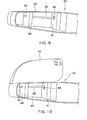
Fig. 1 is a perspective view of a seat for a child according
to the present invention;
Fig. 2 is a side view of the seat for a child according to
the present invention;
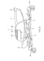
Fig. 3 is a perspective view of the seat for a child when
used as a bed;
Fig. 4 is a view of a connecting constitution of a front leg
member, a rear leg member, and a seat support member;
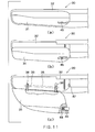
Fig. 5 is a side view of the seat for a child according to
the present invention which is in the lowest collapsed position;
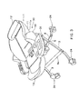
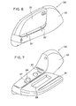
Fig. 6 is a perspective view of an exterior of an armrest;
Fig. 7 is a perspective view of the armrest in which an
upper half member thereof is pivoted into a horizontal posture;
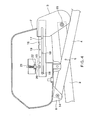
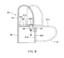
Fig. 8 is a view of a connection between the upper half
member of the armrest and a body part of the armrest, and a
pivoting operation of the upper half member of the armrest
relative to the body part of the armrest;
Fig. 9 is a bottom view of the armrest;
Fig. 10 is a view of the armrest shown in Fig. 9 in which
the upper half member of the armrest is pivoted into the
horizontal posture; and
Fig. 11(a) to 11(c) are views illustrating a pivoting
operation of the upper half member of the armrest.
DETAILED DESCRIPTION OF THE INVENTION
An embodiment of the present invention will be described
below with reference to the accompanied drawings.
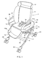
Fig. 1 is a perspective view schematically showing a seat
for a child, and Fig. 2 is a side view thereof. A seat for a child
1 is supported by a pair of right and left X-shaped legs 2. Each
of the X-shaped legs 2 includes a front leg member 3 and a rear
leg member 4 which are pivotally coupled to each other at their
intermediate parts by a pin 5. As shown in Fig. 2, the right and
left front leg members 3 are connected to each other by a front
connection rod 6a, while the rear leg members 4 are connected
to each other by a rear connection rod 6b. An upper end of
each of the rear leg members 4 is pivotally attached to a boss 8
disposed on a front part of a seat support member 7. An upper
end of each of the front leg members 3 is pivotally attached to a
hinge connection 9 which is movably attached to a rear part of
the seat support member 7 in a back and forth direction thereof.
As shown by a two-dot chain line in Fig. 1, the seat support
member 7 is provided with, at an outside surface thereof, a
cover 7a for covering the seat support member 7, the boss 8,
and the hinge connection 9 from above. The seat for a child 1
is mounted on the seat support member 7 in a manner where
the seat can be swung in a back and forth direction.
The X-shaped legs 2 and the seat for a child 1 constitute
a child seat apparatus.
As shown in Figs. 1 and 2, the seat for a child 1 includes
a seat portion 10 on which a child can sit, a back portion 11
disposed on a rear part of the seat portion 10, a headrest 12
disposed on an upper part of the back portion 11, and a leg
portion 13 disposed on a front part of the seat portion 10. The
back portion 11 has a reclining mechanism 11a. Thus, as
shown in Fig. 1, the back portion 11 can take an upright
position, in order that the seat for a child 1 can be used as a
chair. On the other hand, as shown in Fig. 3, the back portion
11 can take a reclined position, in order that the seat for a child
1 can be used as a bed. When the back portion 11 is reclined
in order to use the seat for a child 1 as a bed, the leg portion 13
swings upward in conjunction with a rearward swinging
movement of the back portion 11, so that legs of a child on the
seat for a child 1 can be supported by the leg portion 13. The
leg portion 13 is provided with, at right and left sides thereof,
sidewalls 13a each having a relatively larger thickness. Thus,
when the seat for a child 1 is used as a bed, a child on the seat
for a child 1 can be prevented from tumbling off. In addition,
such a thick sidewall 13a can eliminate an anxious feeling over
the possibility of a child falling off the seat for a child 1.
Fig. 4 is a view showing a connecting constitution of the
front leg member 3, the rear leg member 4, and the seat
support member 7. The upper end of the rear leg member 4 is
pivotally attached to the boss 8 of the seat support member 7
through a pin 14. The upper end of the front leg member 3 is
pivotally attached to the hinge connection 9 through a pin 15.
The hinge connection 9 has a slide bar 16 which is slidably
received in the seat support member 7 in the back and forth
direction. The slide bar 16 is provided with an elongated
opening 17 extending into the hinge connection 9 in the back
and forth direction, i.e., a longitudinal direction of the slide bar
16. The seat support member 7 has two projecting pins 18
which are spaced from each other. The pins 18 are inserted to
the elongated opening 17. By an engagement of the elongated
opening 17 and the pins 18, the slide bar 16 can slide in the
longitudinal direction thereof. The slide bar 16 is urged by a
spring (not shown) in the left direction in Fig. 4, i.e., in a
direction where the X-shaped leg 2 is elongated in a height
direction of the seat for a child 1.
The slide bar 16 is rectangular in section. A plurality of
aligned adjusting holes 19 are formed in an upper surface of the
slide bar 16 in the longitudinal direction. The seat support
member 7 has a pin 20 to be selectively inserted to one of the
adjusting holes 19. The pin 20 is capable of being moved in
the height direction, and is urged by a spring 21 in a direction
where the pin 20 is inserted to the adjusting hole 19. The seat
support member 7 has a lever 22 which is engaged with the pin
20 at a part of a larger diameter. The lever 22 projects
outward from the seat support member 7, and is capable of
being moved in the height direction along the pin 20.
When the lever 22 is drawn upward from the outside of
the seat support member 7, the pin 20 moves upward against
the urging force of the spring 21, so that the pin 20 is
disengaged from one of the adjusting holes 19. After the pin
21 is disengaged from the adjusting hole 19, the slide bar 16 is
moved in the left direction in Fig. 4 by means of a spring force
of a spring (not shown). Therefore, the X-shaped leg 2, which
is formed of the front leg member 3 and the rear leg member 4
hinged to each other, is elongated in the height direction, so
that the seat portion 10 of the seat for a child 1 can be
elevated.
On the other hand, in this elevated state of the seat for a
child 1, when the lever 22 is drawn upward to disengage the pin
20 from the adjusting hole 19 and the seat support member 7 is
pushed downward, the slide bar 16 along with the hinge
connection 9 is moved in the right direction in Fig. 2, so that
inclination angles of the front leg member 3 and the rear leg
member 4 become smaller. When the hinge connection 9
reaches a rightmost position, the pin 20 is engaged with the
leftmost adjusting hole 19. At this time, the seat for a child 1
takes a collapsed position in which the height of the seat portion
10 of the seat for a child 1 is most lowered. The seat for a
child 1 in the lowest position is shown in Fig. 5.
Wheels 24 are attached to lower ends of the respective
front leg members 3 and the rear leg members 4. By means of
the wheels 24, the seat for a child 1 can be easily moved in all
directions, and can move in a small circle. Thus, the seat for a
child 1 can be freely moved in a narrow room.
A pair of armrests 30 each having a relatively larger
thickness are disposed on right and left sides of the seat portion
10. As shown in Fig. 6, each of the armrests 30 has a body
member 32 fixed on the seat portion 10, and an upper half
member 31 separated from the body member 32. The body
member 32 and the upper half member 31 form a horizontal
plane therebetween. As shown in Fig. 6, the upper half
member 31 can take a perpendicular posture, and can be
pivoted outward from the perpendicular posture to a horizontal
posture which is shown in Fig. 7. In this manner, the pivoted
upper half part 31 can serve as a board for an article. An
upper surface 32a of the body member 32 of the armrest 30 is
provided with a recess 34 for a cup or the like. An upper
surface 31a of the outward pivoted upper half member 31 of the
armrest 30 is provided with a recess 33 for an article such as a
diaper or a baby powder container, which can be used when one
changes diapers of a child on the seat for a body 1. Such a
recess may be formed in either the upper surface 32a of the
body member 32 or the upper surface 31a of the upper half
member 31.
As shown in Fig. 8, a shaft 35 extending in the back and
forth direction is disposed in the body member 32 of the
armrest 30. Two links 36, 36 each having an end 36a are
attached to the front and rear parts of the shaft 35. The body
member 32 of the armrest 30 is provided with two corner holes
37 at a corner thereof. Each of the corner holes 37 extends
from the upper surface 32a of the body member 32 to a side
surface thereof. Each of the links 36 passes through the corner
hole 37, with its end 36a projecting outward from the corner
hole 37. The projected link 36 from the corner hole 37 is
rotated about the shaft 35 from a perpendicular position to a
horizontal position, and vice versa. The upper half member 31
of the armrest 30 has an elongated hole 38 in the bottom
surface 31b extending in the right and left direction when the
upper half member 31 takes a perpendicular posture. The end
36a of the link 36 is engaged with the elongated hole 38.
When the upper half part 31 of the armrest 30 moves on the
body member 32, the links 36 move along the elongated hole
38 only in the right and left direction. In this case, the upper
half member 31 slides on the body member 32 in the right and
left direction.
The shaft 35 and the two links 36, 36 constitute the
hinge mechanisms 35, 36, 36.
Figs. 9 and 10 are bottom views of the armrest 30. Both
ends of the shaft 35 are fitted in fitting holes 42 and 43 of
respective brackets 40 and 41 disposed in the body member 32
of the armrest 30. In more detail, the bracket 40 disposed in a
front part of the body member 32 has the circular fitting hole 42,
while the bracket 41 disposed in a rear part of the body member
32 has the elongated fitting hole 43 extending in the right and
left direction of the armrest 30. A front end of the shaft 35 is
fitted in the circular fitting hole 42, and a rear end of the shaft
35 is fitted in the elongated fitting hole 43. The rear end of the
shaft 35 can move along the elongated fitting hole 43 in the
right and left direction, so that an orientation of the shaft 35
can be varied within a predetermined angle in a horizontal
plane.
As shown in Fig. 11(c), a locking member 45 is disposed
on a rear end of the upper half member 31 of the armrest 30.
The locking member 45 is urged by a spring 44 so as to project
rearward. An engagement hole 47 is formed in the body
member 32 of the armrest 30. The locking member 45 can be
engaged with the engagement hole 47 and disengaged
therefrom, by operating an operation button 46 disposed on a
side part of the upper half member 31 of the armrest 30.
When the locking member 45 is engaged with the engagement
hole 47, the upper half member 31 of the armrest 30 can be
maintained at the perpendicular posture (see Fig. 6). When the
locking member 45 is retracted against a spring force of the
spring 44 through the operation button 46 so as to disengage
the locking member 45 from the engagement hole 47, the upper
half member 31 of the armrest 30 can be pivoted into the
horizontal posture (see Fig. 7).
In a use of the seat for a child 1 as a chair as shown in
Fig. 1, the perpendicular posture of the upper half member 31
of the armrest 30 can be maintained by an engagement of the
locking member 45 with the engagement hole 47, which is
shown in Fig. 6. In a use of the seat for a child 1 as a bed on
which one changes diapers of a child, the back portion 11 of the
seat for a child 1 is reclined rearward, and the upper half
member 31 of the armrest 30 is pivoted outward to the
horizontal posture. Thus, one can change diapers of a child
lying on the seat for a child 1, and use the upper surface 31a of
the pivoted upper half member 31 of the armrest 30 as a board
for an article.
In order to pivot the upper half member 31 of the
armrest 30, the locking member 45 is at first disengaged from
the engagement hole 47 through the opening button 46. Then,
as shown by a chain line in Figs. 8 and 11(b), the upper half
member 31 of the armrest 30 is moved outward on the body
member 32. Next, the upper half member 31 of the armrest 30
is rotated about the shaft 35, so that the upper half member 31
of the armrest 30 is pivoted into the horizontal posture as
shown by two dot-chain lines in Fig. 8. In this state, the upper
surface 31a of the pivoted upper half member 31 and the upper
surface 32a of the body member 32 of the armrest 30 are flush
with each other.
When a width of the armrest 30 is decreased toward a
front thereof, the outside side surface of the body member 32 of
the armrest 30 is not parallel with an inside side surface thereof.
In this case, when the upper half part 31 of the armrest 30 is
simply pivoted to the horizontal posture as described above, a
gap might be formed between the outside side surface of the
body member 32 of the armrest 30 and the inside side surface
of the upper half member 31 of the armrest 30, the inside side
surface of the upper half part 31 being opposed to the outside
side surface of the body member 32 of the armrest 30.
However, in the present invention, as described above, an
orientation of the shaft 35 pivotally supporting the upper half
member 31 of the armrest 30 can be varied within a
predetermined angle. Thus, in accordance with a rotating
movement of the upper half member 31 of the armrest 30 about
the shaft 35, the rear end of the shaft 35 moves outward along
the elongated fitting hole 43 of the bracket 41 as shown in Fig.
10, so that the shaft 35 is positioned in parallel with the outside
side surface of the body member 32 of the armrest 30, which is
shown by a chain line in Fig. 11(c). Accordingly, when the
upper half member 31 of the armrest 30 is pivoted outward, the
inside side surface 31b (the bottom surface when in the
perpendicular posture) of the pivoted upper half member 31 of
the armrest 30 comes into contact with the outside side surface
32b of the body member 32 of the armrest 30. At the same
time, the upper surface 31a of the pivoted upper half member
31 of the armrest 30 and the upper surface 32a of the body
member 32 of the armrest 30 are flush with each other, so that
a board for an article is formed. As a result, a space around
the armrest 30 can be effectively utilized.