EP1579816A1 - Verankerungselement und Einrichtung zur dynamischen Stabilisierung von Wirbeln bzw. Knochen - Google Patents
Verankerungselement und Einrichtung zur dynamischen Stabilisierung von Wirbeln bzw. Knochen Download PDFInfo
- Publication number
- EP1579816A1 EP1579816A1 EP05003913A EP05003913A EP1579816A1 EP 1579816 A1 EP1579816 A1 EP 1579816A1 EP 05003913 A EP05003913 A EP 05003913A EP 05003913 A EP05003913 A EP 05003913A EP 1579816 A1 EP1579816 A1 EP 1579816A1
- Authority
- EP
- European Patent Office
- Prior art keywords
- rod
- receiving part
- shaft
- anchoring
- bone
- Prior art date
- Legal status (The legal status is an assumption and is not a legal conclusion. Google has not performed a legal analysis and makes no representation as to the accuracy of the status listed.)
- Granted
Links
Images


Classifications
-
- A—HUMAN NECESSITIES
- A61—MEDICAL OR VETERINARY SCIENCE; HYGIENE
- A61B—DIAGNOSIS; SURGERY; IDENTIFICATION
- A61B17/00—Surgical instruments, devices or methods, e.g. tourniquets
- A61B17/56—Surgical instruments or methods for treatment of bones or joints; Devices specially adapted therefor
- A61B17/58—Surgical instruments or methods for treatment of bones or joints; Devices specially adapted therefor for osteosynthesis, e.g. bone plates, screws, setting implements or the like
- A61B17/68—Internal fixation devices, including fasteners and spinal fixators, even if a part thereof projects from the skin
- A61B17/70—Spinal positioners or stabilisers ; Bone stabilisers comprising fluid filler in an implant
- A61B17/7001—Screws or hooks combined with longitudinal elements which do not contact vertebrae
- A61B17/7035—Screws or hooks, wherein a rod-clamping part and a bone-anchoring part can pivot relative to each other
-
- A—HUMAN NECESSITIES
- A61—MEDICAL OR VETERINARY SCIENCE; HYGIENE
- A61B—DIAGNOSIS; SURGERY; IDENTIFICATION
- A61B17/00—Surgical instruments, devices or methods, e.g. tourniquets
- A61B17/56—Surgical instruments or methods for treatment of bones or joints; Devices specially adapted therefor
- A61B17/58—Surgical instruments or methods for treatment of bones or joints; Devices specially adapted therefor for osteosynthesis, e.g. bone plates, screws, setting implements or the like
- A61B17/68—Internal fixation devices, including fasteners and spinal fixators, even if a part thereof projects from the skin
- A61B17/70—Spinal positioners or stabilisers ; Bone stabilisers comprising fluid filler in an implant
- A61B17/7001—Screws or hooks combined with longitudinal elements which do not contact vertebrae
- A61B17/7002—Longitudinal elements, e.g. rods
- A61B17/701—Longitudinal elements with a non-circular, e.g. rectangular, cross-section
-
- A—HUMAN NECESSITIES
- A61—MEDICAL OR VETERINARY SCIENCE; HYGIENE
- A61B—DIAGNOSIS; SURGERY; IDENTIFICATION
- A61B17/00—Surgical instruments, devices or methods, e.g. tourniquets
- A61B17/56—Surgical instruments or methods for treatment of bones or joints; Devices specially adapted therefor
- A61B17/58—Surgical instruments or methods for treatment of bones or joints; Devices specially adapted therefor for osteosynthesis, e.g. bone plates, screws, setting implements or the like
- A61B17/68—Internal fixation devices, including fasteners and spinal fixators, even if a part thereof projects from the skin
- A61B17/70—Spinal positioners or stabilisers ; Bone stabilisers comprising fluid filler in an implant
- A61B17/7001—Screws or hooks combined with longitudinal elements which do not contact vertebrae
- A61B17/7002—Longitudinal elements, e.g. rods
- A61B17/7011—Longitudinal element being non-straight, e.g. curved, angled or branched
-
- A—HUMAN NECESSITIES
- A61—MEDICAL OR VETERINARY SCIENCE; HYGIENE
- A61B—DIAGNOSIS; SURGERY; IDENTIFICATION
- A61B17/00—Surgical instruments, devices or methods, e.g. tourniquets
- A61B17/56—Surgical instruments or methods for treatment of bones or joints; Devices specially adapted therefor
- A61B17/58—Surgical instruments or methods for treatment of bones or joints; Devices specially adapted therefor for osteosynthesis, e.g. bone plates, screws, setting implements or the like
- A61B17/68—Internal fixation devices, including fasteners and spinal fixators, even if a part thereof projects from the skin
- A61B17/70—Spinal positioners or stabilisers ; Bone stabilisers comprising fluid filler in an implant
- A61B17/7001—Screws or hooks combined with longitudinal elements which do not contact vertebrae
- A61B17/7032—Screws or hooks with U-shaped head or back through which longitudinal rods pass
-
- A—HUMAN NECESSITIES
- A61—MEDICAL OR VETERINARY SCIENCE; HYGIENE
- A61B—DIAGNOSIS; SURGERY; IDENTIFICATION
- A61B17/00—Surgical instruments, devices or methods, e.g. tourniquets
- A61B17/56—Surgical instruments or methods for treatment of bones or joints; Devices specially adapted therefor
- A61B17/58—Surgical instruments or methods for treatment of bones or joints; Devices specially adapted therefor for osteosynthesis, e.g. bone plates, screws, setting implements or the like
- A61B17/68—Internal fixation devices, including fasteners and spinal fixators, even if a part thereof projects from the skin
- A61B17/70—Spinal positioners or stabilisers ; Bone stabilisers comprising fluid filler in an implant
- A61B17/7001—Screws or hooks combined with longitudinal elements which do not contact vertebrae
- A61B17/7035—Screws or hooks, wherein a rod-clamping part and a bone-anchoring part can pivot relative to each other
- A61B17/7037—Screws or hooks, wherein a rod-clamping part and a bone-anchoring part can pivot relative to each other wherein pivoting is blocked when the rod is clamped
-
- A—HUMAN NECESSITIES
- A61—MEDICAL OR VETERINARY SCIENCE; HYGIENE
- A61B—DIAGNOSIS; SURGERY; IDENTIFICATION
- A61B17/00—Surgical instruments, devices or methods, e.g. tourniquets
- A61B17/56—Surgical instruments or methods for treatment of bones or joints; Devices specially adapted therefor
- A61B17/58—Surgical instruments or methods for treatment of bones or joints; Devices specially adapted therefor for osteosynthesis, e.g. bone plates, screws, setting implements or the like
- A61B17/68—Internal fixation devices, including fasteners and spinal fixators, even if a part thereof projects from the skin
- A61B17/70—Spinal positioners or stabilisers ; Bone stabilisers comprising fluid filler in an implant
- A61B17/7001—Screws or hooks combined with longitudinal elements which do not contact vertebrae
- A61B17/7002—Longitudinal elements, e.g. rods
- A61B17/7019—Longitudinal elements having flexible parts, or parts connected together, such that after implantation the elements can move relative to each other
- A61B17/7026—Longitudinal elements having flexible parts, or parts connected together, such that after implantation the elements can move relative to each other with a part that is flexible due to its form
Definitions
- the invention relates to an anchoring element and a stabilizing device for the dynamic stabilization of vertebrae or bone with such an anchoring element.
- rigid fixation and stabilization devices consisting of at least two each in a bone or vertebrae to be anchored and a rigid rod consist of interconnected bone screws.
- an anchoring element according to the preamble of claim 1, which together with a rigid rod for such a rigid stabilizer is used.
- Rigid systems are then used when a relative movement of the bone parts to be stabilized or vertebrae to each other is not desired, e.g. in the presence of fractures or other malpositions.
- a stabilizer which has a allows limited movement of the vertebra to be stabilized.
- a dynamic stabilization device is for example known from US 5,733,284.
- FIG. 9 is the conclusion of a torque M to the Screw axis in a known to the applicant dynamic Stabilizer 200 shown.
- Stabilizer 200 are two bone anchoring elements 202, 202 'via a curved bar 201 connected together with a predetermined bending elasticity.
- the bone anchoring elements 202, 202 ' are with bone screws stuck in two adjacent vertebrae (not here illustrated) anchored.
- FIG. 9 shows the case, that the two bone anchoring elements 202, 202 'with a Force F are compressed.
- the force F acts Bending moment on the rod, resulting in a torque M on the Bone anchoring elements 202, 202 'about the screw axis leads. Accordingly, pulling apart the bone anchoring elements with a force F to a torque M in opposite direction around the screw axis.
- an anchoring element and a dynamic stabilization device for stabilization and to limit the movement of adjacent vertebrae or bones in which the loosening or loosening of the Anchoring element is prevented during operation.
- the object is achieved by an anchoring element according to claim 1 and by a stabilization device according to Claim 12.
- the invention has the advantage that by a rotatable Connection of the bone anchored portion of the anchoring element a loosening or loosening of the relative to the rod Anchoring element by acting on the anchoring element Torques can be effectively prevented.
- the stabilizer is advantageously applicable for decoupling the shaft rotation of head or rod fixation in the dynamic stabilization of vertebrae.
- an anchoring element is included 1 for connecting a bone part or a Vertebrae and a rod 21 with preferably rectangular cross-section according to a first embodiment, a screw element 2, a receiving part 3, a screwed into the receiving part Internal screw 4 and a bearing part 5.
- the screw member 2 has a head 6 in the form of a Ball segment and a threaded shaft 7 for anchoring in the Bones or vertebrae up.
- a threaded shaft 7 for anchoring in the Bones or vertebrae up.
- the head 6 of the screw element 2 flattened and has a recess 8 for engaging an Allen wrench on.
- the receiving part 3 is a substantially cylindrical Body with a first end 9 and an opposite second end 10. Coaxial with its main axis has the Receiving part on a bore 11. Adjacent to the first end 9 is a rectangular recess for receiving the rod 21 12 provided, formed by the two free legs 40, 41 are. The width of the recess is slightly larger than that Length of the narrow side of the rod, while the depth of the recess greater than the length of the broad side of the bar. On the inside of the legs 40, 41 is adjacent to the first end 9 in the bore 11 an internal thread 13 is provided. In a first section adjacent to the first end the bore has a substantially constant inner diameter on, which is larger than the diameter of the head 6 of the screw element 2 is.
- the opening 32 on the side of the second Endes is greater than the diameter of the threaded shaft 7 of the Screw element 2.
- the bearing part 5 has a cylindrical portion with a flat Front side 15 on.
- the diameter of the cylindrical section is chosen so that in the assembled state this section with press fit in the first section of the Receiving part 3 is sitting.
- the bearing part 5 further has a the cylindrical portion adjacent spherical shell-shaped Section 31, whose external shape to the shape of the spherical Seat 14 is adjusted.
- a spherical recess 17 is provided which is the receptacle of the Head 6 of the screw member 2 is used and at the spherical Shape is adapted.
- the inner diameter of the recess 17 is, depending on the desired stiffness of the rotary and Pivoting movement of the screw element relative to the bearing part, in a range of about the same or just slightly larger as the diameter of the head of the screw element.
- Bore 18 is provided with a diameter which the Passing an Allen key to tighten the Screw element 2 allowed but less than the diameter of the head 6 of the screw element 2.
- the spherical shell-shaped Section is a merging into the recess 17 coaxial bore 19 provided whose diameter smaller than the diameter of the head 6 of the screw member 2, but larger than the diameter of the threaded portion 7 is.
- the bearing part 5 in the spherical shell-shaped Section adjacent to the flat Front side opposite side of the bearing part slots 20 on, through which the elasticity of the bearing part is increased.
- the bearing part 5 of a biocompatible Made of plastic, which has good sliding properties.
- PE polyethylene
- UHMWP Ultra-Height Molecular Weight Poly Ethylene
- the internal screw 4 has a coaxial recess 42 for engagement of an Allen key.
- the solid angle range is on the one hand by the diameter of the threaded shaft 7 and on the other hand the diameter of the opening 32 on the side of the second end 10 of the receiving part 3 or the diameter of the coaxial bore 19 fixed in the receiving part 5.
- the Diameter of the spherical recess 17 and the diameter of the head 6 are selected to each other, is the setting different strong frictional forces between head and bearing part and thus the adjustment of the forces that can be overcome must be to the head 6 of the screw element. 2 to turn in the recess 17 of the bearing part 3 and to swing.
- Fig. 3 is a modification 1 'of the anchoring element. 1 illustrated according to the first embodiment, in which the bearing part 5 'in two parts from a first bearing element 5a' and a second bearing element 5b 'is formed.
- the two-piece Bearing part 5 ' is like the bearing part 5, but parallel to Front side cut in two parts.
- the bearing part 5 'can therefore be made of a rigid Material be formed without slots.
- FIGS. 4 to 7 A second embodiment of the invention. Elements similar to those of the first embodiment are provided with the same reference numerals.
- FIG. 4 and 5 includes the anchoring element 100 according to the second embodiment a screw element 2, a receiving part 102, a pressure element 103, a first ring 104, a second ring 105, a first one Bearing part 106, a second bearing part 107, a rod socket 108th and an inner screw 109.
- the screw element 2 in the anchoring element 100 after the second embodiment is identical to the screw element 2 of the anchoring element 1 according to the first embodiment.
- the receiving part 102 is a substantially cylindrical Body having a first end 112 and a first opposite end second end 113.
- a coaxial bore 120 extends from the first end 112 to the second end 113 of the receiving part 102.
- Adjacent to the first end 112 a substantially U-shaped recess 140 is provided, whereby two free legs 114 and 115 are formed. Adjacent to the first end 112 is on the inside of the free Leg 114 and 115, an internal thread 122 is provided.
- the bore 120 has a substantially constant Diameter larger than the diameter of the head 6 of the screw element 2.
- first section subsequent and to the second end of the receiving part 102 extending second section tapers the Bore 120 toward the second end 113.
- Adjacent to the second end 113 is formed a spherical portion 121, its shape to the shape of the head 6 of the screw element 2 is adjusted.
- the diameter of the hole in the second Section is chosen so that it is adjacent to the second End smaller than the diameter of the head 6 of the screw element 2, but larger than the diameter of the threaded shaft 7 of the screw element 2 is.
- the first ring 104 has on its outside an external thread 123 on, with the internal thread 122 on the inside the free leg 114 and 115 of the receiving part 102 cooperates. On an end face 146 of the first ring 104 are provided in the radial direction extending recesses 124, in the a tool for screwing in the first ring 104 can engage in the receiving part 102.
- the second ring 105 is tubular with a constant Outer diameter with a adjacent to a first end 141 first section having a first inner diameter and with a first inner diameter at a second end 142 adjacent second section with a second inner diameter that is larger than the inner diameter of the first section, thereby creating a shoulder 147 is formed.
- the outer diameter of the second ring 105 is constant over the entire length of the ring and something smaller than the diameter of the bore 120 in the at the first end 112 of the receiving part 102 adjacent section, so that the ring 105 is inserted into the bore 120.
- At the first end 141 adjacent is a rectangular recess 143 provided, formed by the two free legs 144, 145 are.
- the width of the recess 143 is like the width of the U-shaped recess 140 of the receiving part 102 is larger than that narrow side of the rectangular cross-section of the rod, so the inserted into these recesses rod 21 in one predetermined angular range, preferably about ⁇ 10 °, back and forth can be swiveled.
- the pressure element 103 has substantially the shape of a flat Cylinder with a spherical recess 111 on the the screw head facing side whose shape to the shape the head 6 of the screw element 2 is adapted, and with an opening into this recess 111 coaxial bore 110 provided for passing a screwdriver.
- Of the Outer diameter of the pressure element 103 is slightly less than the diameter of the bore 120 in the receiving part 102, so the pressure element 103 in the bore of the receiving part is insertable.
- the first and the second ring 104, 105 serve to exercise Pressure on the pressure element 103 and thus for fixing the head 6 of the screw element 2 in the spherical section 121st
- the first bearing part 106 has the shape of a circular disk with a coaxial bore 135 for passing a screwdriver and with a circumferentially extending annular Projection 148, which in the inserted state on the the side facing away from the pressure element.
- the annular projection has two opposite rectangular recesses 149 on.
- the second bearing part 107 is as a tubular portion formed with a flange-like projection 151, wherein the Diameter of the tubular portion is less than that Diameter of the first bearing part 106.
- the outer diameter the flange-like projection 151 of the second bearing part 107 is equal to the diameter of the first bearing part 106.
- Adjacent to the side with the flange-like projection 151 are two opposite rectangular recesses 150 provided.
- the first and the second bearing part 106, 107 are used in the State coaxially arranged so that the annular projection 148 of the first bearing part 106 to the flange-like approach 151 of the second bearing part 107 adjacent, wherein the rectangular Recesses 149, 150 in the two bearing parts 106, 107 are aligned with each other, so in the by the two bearing parts 106, 107 bearings formed two opposite, opening into the interior of the warehouse are designed for receiving the rod.
- In width are through the recesses 149, 150 in the assembled state trained openings designed so that by these openings inserted rod 21 in a predetermined angular range, preferably about ⁇ 10 °, to be pivoted back and forth can.
- the height of the recesses 149, 150 in the composite Condition formed openings is slightly larger than the corresponding cross-sectional side of the rod 21.
- the outer diameter of the warehouse is just such that one Press fitting of the bearing in the first and second clamping ring is possible.
- the flange When assembled, the flange is located Approach 151 on the shoulder 147 of the second ring 105 at.
- the first and second bearing members 106, 107 are preferably made of a biocompatible plastic, the good Has sliding properties. Preference is given to polyethylene (PE) used. Here, different degrees of crosslinking with resulting in different molecular weights, such as e.g. LDPE and LLDPE with molecular weights of up to 50,000 g / mol, HDPE with molecular weights up to 200,000 g / mol or UHMWP (Ultra-Height Molecular Weight Poly Ethylene) with molecular weights around 6,000,000 g / mol. Prefers is for the bearing part due to its low long-term wear UHMWP used. The remaining parts of the anchoring element are preferred from a biocompatible Material with good mechanical properties, e.g. Titanium, manufactured.
- FIG Bar frame 108 as a cylindrical body with a first End 130 and a second end 131 is formed. From the first End 130 is a continuous one up to the second end 131 coaxial bore 132 is provided. Adjacent to the first end 130, an internal thread 155 is provided in the bore 132, in FIG that the inner screw 109 can be screwed.
- the outer diameter the rod socket 108 is slightly smaller than the Inner diameter of the second bearing part 107.
- the rod socket 108 has a flange-like approach 152, whose outer diameter is slightly smaller than the inner diameter of the first bearing part 106 is.
- On the side walls the rod socket 108 are two opposing openings 133 provided with rectangular cross-section.
- the width B of Opening is slightly larger than the width of the bar.
- the height H the opening is larger than the height of the bar.
- the inner screw 109 has an external thread 154, which with the internal thread 155 of the rod socket 108 cooperates.
- a Coaxial bore 134 through the inner screw 109 has a Cross-section on which to engage with an Allen key suitable is.
- the axial Length of the female threaded portion 155 of the rod socket 108 and the height of the openings 133 chosen so that the rod through Tighten the inner screw 109 from a position in which he in the opening is displaceable, in a position in which he pressed against the lower edge 153 of the opening 133 and fixed so becomes, is displaceable.
- the pre-assembly of the anchoring element is first the screw member 2 with the threaded shaft 7 in advance introduced the receiving part 102, so that the head 6 at the spherical surface 121 is applied. Following this is by the first end 112 of the receiving part 102 ago in the coaxial Hole 120 of the receiving part 102, first the pressure element 103rd inserted with the spherical recess 111 towards the head, then the first bearing part 106 with the coaxial Bore ahead inserted into the receiving part 102 and then is the rod socket 108 with previously slightly screwed Internal screw 109 inserted into the first bearing part 106.
- the second bearing part 107 and the second Ring 105 between the side wall of the receiving part 102 and the first and second bearing part 106, 107 introduced is successively the second bearing part 107 and the second Ring 105 between the side wall of the receiving part 102 and the first and second bearing part 106, 107 introduced.
- the first ring 104 in the receiving part 102 is just so far screwed in that falling out of the in the receiving part 102 introduced elements is prevented.
- the Pre-assembly of the anchoring element 100 completed.
- the rod socket 108, the first and the second bearing part 106, 107, the first and the second Ring 104, 105 and the inner screw 109 also outside first composed of the receiving part and only then in the receiving part be introduced.
- Other types of assembly are possible.
- the rod socket 108 with the fixed rod-shaped element 21 about the major axis of the receiving part 102 in a predetermined angular range can turn.
- the angular range is determined by the dimension of the rod 21 and the width of the recess 140 in the receiving part 102, the width of the rectangular recesses 149, 150th in the first and the second bearing part 106, 107 of the openings 149 and the width of the recesses 143 in the second Ring 105 set.
- the rod holder 108 rotates with the Rod 21 with, while the bearing member 106, 107 by press fitting firmly seated in the first and second rings 104, 105.
- the angular position the screw axis relative to the receiving part 102nd remains.
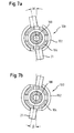
- Figures 7a and 7b are two different limit angle positions ⁇ , ⁇ of the rod-shaped element 21 with respect to Receiving part 102 shown.
- the three rotational degrees of freedom of the rod relative has the screw element, the connection with a Anchoring element 100 according to the second embodiment only a rotational degree of freedom.
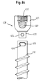
- a third embodiment of the invention is a rotatable connection between a rod and a bone or Whirl produced thereby, by as shown in Fig. 8a in a polyaxial screw, where the angle between rod 407 and receiving part 408, as well as between screw element and Receiving part is fixed, a two-part screw element 400 is used, in which the head 401 of the screw element is rotatably connected to the threaded shaft 412.
- the polyaxial screw includes a receiving part as shown in Fig. 8a 408, a pressure element 409, an inner screw 410 and a male screw 411.
- a pin 404 which along its longitudinal axis against a spring force in the neck 403 is depressible.
- the threaded shaft 412 has at its the head 401 of the screw member 400 facing side a coaxial recess 405, in which the neck 403 engages.
- This recess 405 is a slot 406 is provided, in which the pin 404 engages.
- the pin is pressed down into the neck so that the neck 403 into the recess 405 of the threaded shaft 412 can be inserted.
- the neck 403 is then in the Recess 405 inserted that the pin 404 of the spring force pushed outward into the slot 406 in the wall of the Recess 405 engages.
- This will create a connection between the head 401 and the threaded shaft 412 of the screw element 400 formed at the head 401 against the threaded shaft 412 of the screw member within a through the Length of the slot 406 predetermined angular range coaxial can be turned against each other.
- the screw member 400 is then in a receiving part 408th inserted and screwed into the bone. Subsequently, will in a known manner, the position of the screw member to the receiving part fixed, as well as the rod 407 inserted and fixed.
- connection with an anchoring element after the third Embodiment has as in the second embodiment Rotational degree of freedom.
- the bone anchoring element 420 as a monoaxial screw formed, in which the receiving part 421 firmly is connected to the head of the two-part screw element or an integral part thereof. Otherwise it is the bone anchoring element 420 as previously described Third embodiment formed.
- the opening 19 of the anchoring element according to the first embodiment was described as being smaller in diameter than that of the head 6, but larger than the diameter of the head Threaded section 7 is.
- the diameter of the opening 19 can but also smaller than the diameter of the threaded shaft 7 be when the screw member 2 is formed in two parts, so that the threaded shaft during assembly is not through the opening 19 must be passed. It is also possible that the opening is formed so that the screw element can be screwed through it.
- the anchoring element according to the first embodiment may be a non-spherical but with respect to the screw axis rotationally symmetric shape of the head is a limitation of Rotary movement of the screw element relative to the receiving part effect on one degree of freedom.
- the bearing part 5 after The first embodiment does not necessarily have at least one or more slots 20 when the elasticity of the material used an introduction of the head 6 of the Screw element 2 without slots 20 allowed.
- the diameter of the bore 120 in the second section of the Receiving part 102 according to the second embodiment is so described that he was adjacent to the second end 113th larger than the diameter of the threaded shaft 7 of the screw element 2 is.
- the diameter of the bore 120 can adjacent to the second end also be sized so that the Screw member is screwed through the hole or but, in a multi-part screw element, lower is as the diameter of the threaded shaft 7, in this Case does not have to be passed through the bore 120, but from the outside with the located in the receiving part Head is connected.
- first bearing part 106 can also be without the projection 148 be formed.
- the anchoring element 100 according to the second embodiment can be designed as a monoaxial screw, in which the receiving part 102 is firmly connected to the screw member 2 or an integral part thereof.
- anchoring elements may instead anchoring with a screw element another kind of Anchoring be provided in the bone or vertebra, such as e.g. anchoring by hooks.
- the bone anchoring elements after the first and the second Embodiment of the invention were for rod-shaped elements described with square cross section.
- this bone anchoring element can also for the use of rod-shaped elements with a circular or another cross-section.
- the bone anchoring element after the third Embodiment for use with a rod-shaped Element with a rectangular or a different cross-section be modified.
- the pin 404 pressed against a spring force in the neck 403 can be.
- the pin 404 can also be press-fitted placed in a hole in the neck 403 and 422 and so firm be connected to the neck 403 and 422, respectively.
- the neck first without a pin in the recess 405th and then the pin through the slot 406 therethrough into the hole in the neck.
- the Pin and neck so that the pin with a External thread in a provided in the hole of the neck internal thread can be screwed.
- Rotary connections between the screw head 401 and the threaded portion 402 is possible.
- a stabilizing device for the dynamic Stabilization of bones or vertebrae exists as the in Fig. 9 known stabilizer at least two connected to a rod-shaped element Bone anchoring elements of which at least one Bone anchoring element according to the first to third embodiments is.
Landscapes
- Health & Medical Sciences (AREA)
- Orthopedic Medicine & Surgery (AREA)
- Life Sciences & Earth Sciences (AREA)
- Neurology (AREA)
- Surgery (AREA)
- Heart & Thoracic Surgery (AREA)
- Engineering & Computer Science (AREA)
- Biomedical Technology (AREA)
- Nuclear Medicine, Radiotherapy & Molecular Imaging (AREA)
- Medical Informatics (AREA)
- Molecular Biology (AREA)
- Animal Behavior & Ethology (AREA)
- General Health & Medical Sciences (AREA)
- Public Health (AREA)
- Veterinary Medicine (AREA)
- Surgical Instruments (AREA)
- Prostheses (AREA)
Abstract
Description
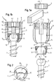
- Fig. 1a
- eine Explosionsdarstellung eines Verankerungselementes nach einer ersten Ausführungsform der Erfindung;
- Fig. 1b
- eine teilgeschnittene Ansicht des Verankerungselements nach der ersten Ausführungsform der Erfindung mit einem eingelegten Stab;
- FIG. 2
- eine perspektivische Ansicht eines Lagerteils, das bei der ersten Ausführungsform der Erfindung verwendet wird;
- Fig. 3
- Eine Abwandlung des Verankerungselementes nach der ersten Ausführungsform;
- Fig. 4
- eine Explosionsdarstellung eines Verankerungselementes nach einer zweiten Ausführungsform der Erfindung;
- Fig. 5
- eine teilgeschnittene Darstellung des Verankerungselementes nach der zweiten Ausführungsform der Erfindung;
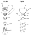
- Fig. 6a
- eine Seitenansicht der Stabfassung des Verankerungselements nach der zweiten Ausführungsform mit eingelegtem Stab und mit noch nicht vollständig eingeschraubter Innenschraube;
- Fig. 6b
- eine Schnittdarstellung der Stabfassung des Verankerungselements nach der zweiten Ausführungsform mit eingelegtem Stab und mit vollständig eingeschraubter Innenschraube;
- Fig. 7a und 7b
- ein Verankerungselement nach der zweiten Ausführungsform der Erfindung in zwei verschiedenen Winkelstellungen des stabförmigen Elements relativ zum Aufnahmeteil;
- Fig. 8a
- eine Explosionsdarstellung eines Verankerungselements nach einer dritten Ausführungsform der Erfindung;
- Fig. 8b
- Knochenschraube mit drehbarer Verbindung zwischen Kopf und Verankerungsabschnitt die bei der dritten Ausführungsform der Erfindung verwendet wird;
- Fig. 8c
- Abwandlung des Verankerungselementes aus Fig. 8a und 8b; und
- Fig. 9
- das Zustandekommen eines Drehmomentes auf eine Knochenschraube bei einer der Anmelderin bekannten dynamischen Stabilisierungsvorrichtung.;
Claims (13)
- Verankerungselement (1, 1', 100, 415, 420) zum Verankern eines stabförmigen Elements (21, 407) in einem Knochen oder Wirbel
mit einem in dem Knochen oder Wirbel zu verankernden Schaft (7, 412),
einem mit dem Schaft (7, 412) verbundenen Aufnahmeteil (3, 102, 408, 421) zur Aufnahme des stabförmigen Elements (21, 407), und
einer Fixationsvorrichtung (4, 109, 410) zum Fixieren des stabförmigen Elements (21, 407) in dem Aufnahmeteil (3, 102, 408, 421),
dadurch gekennzeichnet, daß in fixiertem Zustand des stabförmigen Elements (21, 407) der Schaft (7, 412) über das Aufnahmeteil (3, 102, 408, 421) mit dem stabförmigen Element (21, 407) derart beweglich verbunden ist, daß der Schaft (7, 412) relativ zu dem stabförmigen Element (21, 407) eine Bewegung mit wenigstens einem Rotationsfreiheitsgrad, aber keinem Translationsfreiheitsgrad ausführen kann. - Verankerungselement (100) nach Anspruch 1, wobei der Schaft (7) mit dem Aufnahmeteil (102) fest verbunden ist und das stabförmige Element (21) in einer Fassung (108) in dem Aufnahmeteil (102) drehbar gehalten ist.
- Verankerungselement (100) nach Anspruch 2,
wobei die Fassung (108) in einem Lagerelement (106, 107) drehbar gelagert ist. - Verankerungselement (100) nach Anspruch 3, das als Polyaxialschraube mit einem aus dem Schaft (7) und einem kugelsegmentförmigen Kopf (6) bestehenden Knochenverankerungselement (2) ausgebildet ist, wobei
an das eine Ende des Aufnahmeteils (102) angrenzend ein sphärischer Sitz (121) zur Aufnahme des kugelsegmentförmigen Kopfes (6) des Knochenverankerungselementes (2) vorgesehen ist,
an das andere Ende des Aufnahmeteils (102) angrenzend zwei sich gegenüberliegende Ausnehmungen (140) vorgesehen sind, durch die zwei freie Schenkel (114, 115) gebildet werden,
an den Innenseiten der freien Schenkel (114, 115) ein Gewinde (122) vorgesehen ist, in welches ein ringförmiges Element (104) einschraubbar ist, mit dem direkt oder indirekt Druck auf ein Druckelement (103) ausgeübt wird, welches diesen Druck wiederum an den Kopf (6) des Knochenverankerungselementes (2) weitergibt, sodass das Knochenverankerungselement (2) in einer vorbestimmten Winkelstellung relativ zu dem Aufnahmeteil (102) fixiert wird, wobei
das Lagerelement (106, 107) innerhalb des ringförmigen Elementes (104) sitzt. - Verankerungselement (100) nach Anspruch 4, wobei das Lagerelement (106, 107) durch Presspassung fest mit dem ringförmigen Element (104) verbunden ist.
- Verankerungselement (1, 1') nach Anspruch 1 , wobei angrenzend an den Schaft (7) ein Kopf (6) vorgesehen ist, der in dem Aufnahmeteil (3) in einem Lagerelement (5, 5') relativ zum dem stabförmigen Element drehbar gehalten ist.
- Verankerungselement (1, 100) nach einem der Ansprüche 3 bis 6, wobei das Lagerelement (5, 106, 107) aus körperverträglichem Kunststoff, bevorzugt aus Polyethylen ausgeführt ist.
- Verankerungselement (415) nach Anspruch 1, wobei angrenzend an den Schaft (412) ein Kopf (401) vorgesehen ist, der in dem Aufnahmeteil (408) so fixierbar ist, daß der Schaft (412) eine vorgegebene Winkelstellung relativ zu dem Aufnahmeteil (408) aufweist und wobei der Kopf (401) und der Schaft (412) separate Teile sind, die drehbar miteinander verbunden sind.
- Verankerungselement (420) nach Anspruch 1, wobei angrenzend an den Schaft (412) ein Kopf vorgesehen ist, der mit dem Aufnahmeteil (421) fest verbunden ist bzw. ein integraler Bestandteil desselben ist und wobei der Kopf und der Schaft (412) separate Teile sind, die drehbar miteinander verbunden sind.
- Verankerungselement (1, 1', 100, 415, 420) nach einem der Ansprüche 1 bis 9, wobei ein Anschlag (149, 150, 406) zum Begrenzen der Drehbewegung vorgesehen ist.
- Verankerungselement nach einem der Ansprüche 1 bis 10, wobei der in dem Knochen oder Wirbel zu verankernde Schaft (7, 412) ein Knochengewinde aufweist.
- Stabilisierungseinrichtung (200) mit wenigstens zwei Verankerungselementen (202, 202') und einem diese verbindenden stabförmigen Element (201), wobei
wenigstens ein Verankerungselement nach einem der Ansprüche 1 bis 11 ausgebildet ist. - Verankerungselement (1, 1', 100, 415, 420) zum Verankern eines stabförmigen Elements (21, 407) in einem Knochen oder Wirbel
mit einem in dem Knochen oder Wirbel zu verankernden Schaft (7, 412),
einem mit dem Schaft (7, 412) verbundenen Aufnahmeteil (3, 102, 408, 421) zur Aufnahme des stabförmigen Elements (21, 407), und
einer Fixationsvorrichtung (4, 109, 410) zum Fixieren des stabförmigen Elements (21, 407) in dem Aufnahmeteil (3, 102, 408, 421),
dadurch gekennzeichnet, daß in fixiertem Zustand des stabförmigen Elements (21, 407) der Schaft (7, 412) über das Aufnahmeteil (3, 102, 408, 421) mit dem stabförmigen Element (21, 407) drehbar verbunden ist, und
eine Führungsfläche vorgesehen ist, welche die relative Bewegung zwischen dem Schaft (7, 412) und dem stabförmigen Element (21, 407) auf einen Rotationsfreiheitsgrad einschränkt.
Priority Applications (1)
| Application Number | Priority Date | Filing Date | Title |
|---|---|---|---|
| EP10186228.2A EP2286747B1 (de) | 2004-03-03 | 2005-02-23 | Verankerungselement und Einrichtung zur dynamischen Stabilisierung von Wirbeln bzw. Knochen |
Applications Claiming Priority (4)
| Application Number | Priority Date | Filing Date | Title |
|---|---|---|---|
| US55000804P | 2004-03-03 | 2004-03-03 | |
| DE102004010380A DE102004010380A1 (de) | 2004-03-03 | 2004-03-03 | Verankerungselement und Stabilisierungseinrichtung zur dynamischen Stabilisierung von Wirbeln bzw. Knochen mit einem solchen Verankerungselement |
| US550008P | 2004-03-03 | ||
| DE102004010380 | 2004-03-03 |
Related Child Applications (2)
| Application Number | Title | Priority Date | Filing Date |
|---|---|---|---|
| EP10186228.2A Division EP2286747B1 (de) | 2004-03-03 | 2005-02-23 | Verankerungselement und Einrichtung zur dynamischen Stabilisierung von Wirbeln bzw. Knochen |
| EP10186228.2 Division-Into | 2010-10-01 |
Publications (2)
| Publication Number | Publication Date |
|---|---|
| EP1579816A1 true EP1579816A1 (de) | 2005-09-28 |
| EP1579816B1 EP1579816B1 (de) | 2013-06-19 |
Family
ID=34877306
Family Applications (2)
| Application Number | Title | Priority Date | Filing Date |
|---|---|---|---|
| EP10186228.2A Active EP2286747B1 (de) | 2004-03-03 | 2005-02-23 | Verankerungselement und Einrichtung zur dynamischen Stabilisierung von Wirbeln bzw. Knochen |
| EP05003913.0A Active EP1579816B1 (de) | 2004-03-03 | 2005-02-23 | Verankerungselement und Einrichtung zur dynamischen Stabilisierung von Wirbeln bzw. Knochen |
Family Applications Before (1)
| Application Number | Title | Priority Date | Filing Date |
|---|---|---|---|
| EP10186228.2A Active EP2286747B1 (de) | 2004-03-03 | 2005-02-23 | Verankerungselement und Einrichtung zur dynamischen Stabilisierung von Wirbeln bzw. Knochen |
Country Status (4)
| Country | Link |
|---|---|
| US (3) | US8808330B2 (de) |
| EP (2) | EP2286747B1 (de) |
| JP (1) | JP4817676B2 (de) |
| DE (1) | DE102004010380A1 (de) |
Cited By (55)
| Publication number | Priority date | Publication date | Assignee | Title |
|---|---|---|---|---|
| EP1741396A1 (de) * | 2005-07-08 | 2007-01-10 | BIEDERMANN MOTECH GmbH | Knochenverankerungsvorrichtung |
| US7662175B2 (en) | 2003-06-18 | 2010-02-16 | Jackson Roger P | Upload shank swivel head bone screw spinal implant |
| US7766915B2 (en) | 2004-02-27 | 2010-08-03 | Jackson Roger P | Dynamic fixation assemblies with inner core and outer coil-like member |
| US7806913B2 (en) | 2006-08-16 | 2010-10-05 | Depuy Spine, Inc. | Modular multi-level spine stabilization system and method |
| US7875065B2 (en) | 2004-11-23 | 2011-01-25 | Jackson Roger P | Polyaxial bone screw with multi-part shank retainer and pressure insert |
| US7901437B2 (en) | 2007-01-26 | 2011-03-08 | Jackson Roger P | Dynamic stabilization member with molded connection |
| US7942910B2 (en) | 2007-05-16 | 2011-05-17 | Ortho Innovations, Llc | Polyaxial bone screw |
| US7942911B2 (en) | 2007-05-16 | 2011-05-17 | Ortho Innovations, Llc | Polyaxial bone screw |
| US7942909B2 (en) | 2009-08-13 | 2011-05-17 | Ortho Innovations, Llc | Thread-thru polyaxial pedicle screw system |
| US7947065B2 (en) | 2008-11-14 | 2011-05-24 | Ortho Innovations, Llc | Locking polyaxial ball and socket fastener |
| US7951170B2 (en) | 2007-05-31 | 2011-05-31 | Jackson Roger P | Dynamic stabilization connecting member with pre-tensioned solid core |
| US7951173B2 (en) | 2007-05-16 | 2011-05-31 | Ortho Innovations, Llc | Pedicle screw implant system |
| US7967850B2 (en) | 2003-06-18 | 2011-06-28 | Jackson Roger P | Polyaxial bone anchor with helical capture connection, insert and dual locking assembly |
| US8012177B2 (en) | 2007-02-12 | 2011-09-06 | Jackson Roger P | Dynamic stabilization assembly with frusto-conical connection |
| US8012182B2 (en) | 2000-07-25 | 2011-09-06 | Zimmer Spine S.A.S. | Semi-rigid linking piece for stabilizing the spine |
| US8066739B2 (en) | 2004-02-27 | 2011-11-29 | Jackson Roger P | Tool system for dynamic spinal implants |
| US8075603B2 (en) | 2008-11-14 | 2011-12-13 | Ortho Innovations, Llc | Locking polyaxial ball and socket fastener |
| US8092502B2 (en) | 2003-04-09 | 2012-01-10 | Jackson Roger P | Polyaxial bone screw with uploaded threaded shank and method of assembly and use |
| US8092500B2 (en) | 2007-05-01 | 2012-01-10 | Jackson Roger P | Dynamic stabilization connecting member with floating core, compression spacer and over-mold |
| US8100915B2 (en) | 2004-02-27 | 2012-01-24 | Jackson Roger P | Orthopedic implant rod reduction tool set and method |
| US8105368B2 (en) | 2005-09-30 | 2012-01-31 | Jackson Roger P | Dynamic stabilization connecting member with slitted core and outer sleeve |
| US8128667B2 (en) | 2002-09-06 | 2012-03-06 | Jackson Roger P | Anti-splay medical implant closure with multi-surface removal aperture |
| US8137386B2 (en) | 2003-08-28 | 2012-03-20 | Jackson Roger P | Polyaxial bone screw apparatus |
| US8197518B2 (en) | 2007-05-16 | 2012-06-12 | Ortho Innovations, Llc | Thread-thru polyaxial pedicle screw system |
| US8257398B2 (en) | 2003-06-18 | 2012-09-04 | Jackson Roger P | Polyaxial bone screw with cam capture |
| US8257402B2 (en) | 2002-09-06 | 2012-09-04 | Jackson Roger P | Closure for rod receiving orthopedic implant having left handed thread removal |
| US8273089B2 (en) | 2004-11-23 | 2012-09-25 | Jackson Roger P | Spinal fixation tool set and method |
| US8273109B2 (en) | 2002-09-06 | 2012-09-25 | Jackson Roger P | Helical wound mechanically interlocking mating guide and advancement structure |
| US8292926B2 (en) | 2005-09-30 | 2012-10-23 | Jackson Roger P | Dynamic stabilization connecting member with elastic core and outer sleeve |
| US8308782B2 (en) | 2004-11-23 | 2012-11-13 | Jackson Roger P | Bone anchors with longitudinal connecting member engaging inserts and closures for fixation and optional angulation |
| US8353932B2 (en) | 2005-09-30 | 2013-01-15 | Jackson Roger P | Polyaxial bone anchor assembly with one-piece closure, pressure insert and plastic elongate member |
| US8366753B2 (en) | 2003-06-18 | 2013-02-05 | Jackson Roger P | Polyaxial bone screw assembly with fixed retaining structure |
| US8366745B2 (en) | 2007-05-01 | 2013-02-05 | Jackson Roger P | Dynamic stabilization assembly having pre-compressed spacers with differential displacements |
| US8377100B2 (en) | 2000-12-08 | 2013-02-19 | Roger P. Jackson | Closure for open-headed medical implant |
| US8377102B2 (en) | 2003-06-18 | 2013-02-19 | Roger P. Jackson | Polyaxial bone anchor with spline capture connection and lower pressure insert |
| US8398682B2 (en) | 2003-06-18 | 2013-03-19 | Roger P. Jackson | Polyaxial bone screw assembly |
| US8409256B2 (en) | 2006-12-28 | 2013-04-02 | Depuy Spine, Inc. | Spinal anchoring screw |
| US8444681B2 (en) | 2009-06-15 | 2013-05-21 | Roger P. Jackson | Polyaxial bone anchor with pop-on shank, friction fit retainer and winged insert |
| US9198695B2 (en) | 2010-08-30 | 2015-12-01 | Zimmer Spine, Inc. | Polyaxial pedicle screw |
| US9743957B2 (en) | 2004-11-10 | 2017-08-29 | Roger P. Jackson | Polyaxial bone screw with shank articulation pressure insert and method |
| US9907574B2 (en) | 2008-08-01 | 2018-03-06 | Roger P. Jackson | Polyaxial bone anchors with pop-on shank, friction fit fully restrained retainer, insert and tool receiving features |
| US9918745B2 (en) | 2009-06-15 | 2018-03-20 | Roger P. Jackson | Polyaxial bone anchor with pop-on shank and winged insert with friction fit compressive collet |
| US9980753B2 (en) | 2009-06-15 | 2018-05-29 | Roger P Jackson | pivotal anchor with snap-in-place insert having rotation blocking extensions |
| US10039577B2 (en) | 2004-11-23 | 2018-08-07 | Roger P Jackson | Bone anchor receiver with horizontal radiused tool attachment structures and parallel planar outer surfaces |
| US10039578B2 (en) | 2003-12-16 | 2018-08-07 | DePuy Synthes Products, Inc. | Methods and devices for minimally invasive spinal fixation element placement |
| US10076361B2 (en) | 2005-02-22 | 2018-09-18 | Roger P. Jackson | Polyaxial bone screw with spherical capture, compression and alignment and retention structures |
| US10194951B2 (en) | 2005-05-10 | 2019-02-05 | Roger P. Jackson | Polyaxial bone anchor with compound articulation and pop-on shank |
| US10258382B2 (en) | 2007-01-18 | 2019-04-16 | Roger P. Jackson | Rod-cord dynamic connection assemblies with slidable bone anchor attachment members along the cord |
| US10299839B2 (en) | 2003-12-16 | 2019-05-28 | Medos International Sárl | Percutaneous access devices and bone anchor assemblies |
| US10363070B2 (en) | 2009-06-15 | 2019-07-30 | Roger P. Jackson | Pivotal bone anchor assemblies with pressure inserts and snap on articulating retainers |
| US10383660B2 (en) | 2007-05-01 | 2019-08-20 | Roger P. Jackson | Soft stabilization assemblies with pretensioned cords |
| US10470801B2 (en) | 2007-01-18 | 2019-11-12 | Roger P. Jackson | Dynamic spinal stabilization with rod-cord longitudinal connecting members |
| US10729469B2 (en) | 2006-01-09 | 2020-08-04 | Roger P. Jackson | Flexible spinal stabilization assembly with spacer having off-axis core member |
| US10792074B2 (en) | 2007-01-22 | 2020-10-06 | Roger P. Jackson | Pivotal bone anchor assemly with twist-in-place friction fit insert |
| US11419642B2 (en) | 2003-12-16 | 2022-08-23 | Medos International Sarl | Percutaneous access devices and bone anchor assemblies |
Families Citing this family (166)
| Publication number | Priority date | Publication date | Assignee | Title |
|---|---|---|---|---|
| US7833250B2 (en) | 2004-11-10 | 2010-11-16 | Jackson Roger P | Polyaxial bone screw with helically wound capture connection |
| US7862587B2 (en) | 2004-02-27 | 2011-01-04 | Jackson Roger P | Dynamic stabilization assemblies, tool set and method |
| US8876868B2 (en) | 2002-09-06 | 2014-11-04 | Roger P. Jackson | Helical guide and advancement flange with radially loaded lip |
| US7377923B2 (en) | 2003-05-22 | 2008-05-27 | Alphatec Spine, Inc. | Variable angle spinal screw assembly |
| US8926670B2 (en) | 2003-06-18 | 2015-01-06 | Roger P. Jackson | Polyaxial bone screw assembly |
| US7322981B2 (en) * | 2003-08-28 | 2008-01-29 | Jackson Roger P | Polyaxial bone screw with split retainer ring |
| EP1699371A4 (de) * | 2003-12-30 | 2008-09-24 | Depuy Spine Sarl | Knochenankeranordnungen |
| US7160300B2 (en) | 2004-02-27 | 2007-01-09 | Jackson Roger P | Orthopedic implant rod reduction tool set and method |
| US11241261B2 (en) | 2005-09-30 | 2022-02-08 | Roger P Jackson | Apparatus and method for soft spinal stabilization using a tensionable cord and releasable end structure |
| DE102004010380A1 (de) * | 2004-03-03 | 2005-09-22 | Biedermann Motech Gmbh | Verankerungselement und Stabilisierungseinrichtung zur dynamischen Stabilisierung von Wirbeln bzw. Knochen mit einem solchen Verankerungselement |
| DE102004010844A1 (de) * | 2004-03-05 | 2005-10-06 | Biedermann Motech Gmbh | Stabilisierungseinrichtung zur dynamischen Stabilisierung von Wirbeln oder Knochen und stabförmiges Element für eine derartige Stabilisierungseinrichtung |
| EP1768585B1 (de) * | 2004-07-12 | 2012-01-04 | Synthes GmbH | Vorrichtung zur dynamischen fixierung von knochen |
| US8114158B2 (en) | 2004-08-03 | 2012-02-14 | Kspine, Inc. | Facet device and method |
| US7651502B2 (en) | 2004-09-24 | 2010-01-26 | Jackson Roger P | Spinal fixation tool set and method for rod reduction and fastener insertion |
| US7604655B2 (en) * | 2004-10-25 | 2009-10-20 | X-Spine Systems, Inc. | Bone fixation system and method for using the same |
| JP2008517733A (ja) * | 2004-10-25 | 2008-05-29 | アルファスパイン インコーポレイテッド | ペディクルねじシステムおよび、該システムの組立/設置法 |
| CA2586361A1 (en) | 2004-11-10 | 2006-05-18 | Roger P. Jackson | Helical guide and advancement flange with break-off extensions |
| US8926672B2 (en) | 2004-11-10 | 2015-01-06 | Roger P. Jackson | Splay control closure for open bone anchor |
| AU2005306355A1 (en) * | 2004-11-19 | 2006-05-26 | Alphaspine, Inc. | Rod-coupling assemblies |
| WO2006057837A1 (en) | 2004-11-23 | 2006-06-01 | Jackson Roger P | Spinal fixation tool attachment structure |
| US9168069B2 (en) | 2009-06-15 | 2015-10-27 | Roger P. Jackson | Polyaxial bone anchor with pop-on shank and winged insert with lower skirt for engaging a friction fit retainer |
| US9216041B2 (en) | 2009-06-15 | 2015-12-22 | Roger P. Jackson | Spinal connecting members with tensioned cords and rigid sleeves for engaging compression inserts |
| US9393047B2 (en) | 2009-06-15 | 2016-07-19 | Roger P. Jackson | Polyaxial bone anchor with pop-on shank and friction fit retainer with low profile edge lock |
| WO2006058221A2 (en) | 2004-11-24 | 2006-06-01 | Abdou Samy M | Devices and methods for inter-vertebral orthopedic device placement |
| US9339301B2 (en) | 2004-12-30 | 2016-05-17 | Mark A. Barry | System and method for aligning vertebrae in the amelioration of aberrant spinal column deviation conditions |
| US20060264252A1 (en) * | 2005-05-23 | 2006-11-23 | White Gehrig H | System and method for providing a host console for use with an electronic card game |
| US7717943B2 (en) | 2005-07-29 | 2010-05-18 | X-Spine Systems, Inc. | Capless multiaxial screw and spinal fixation assembly and method |
| US7955358B2 (en) | 2005-09-19 | 2011-06-07 | Albert Todd J | Bone screw apparatus, system and method |
| US7686835B2 (en) * | 2005-10-04 | 2010-03-30 | X-Spine Systems, Inc. | Pedicle screw system with provisional locking aspects |
| US20070118117A1 (en) | 2005-10-20 | 2007-05-24 | Ebi, L.P. | Bone fixation assembly |
| US8357181B2 (en) | 2005-10-27 | 2013-01-22 | Warsaw Orthopedic, Inc. | Intervertebral prosthetic device for spinal stabilization and method of implanting same |
| US8100946B2 (en) * | 2005-11-21 | 2012-01-24 | Synthes Usa, Llc | Polyaxial bone anchors with increased angulation |
| US7704271B2 (en) | 2005-12-19 | 2010-04-27 | Abdou M Samy | Devices and methods for inter-vertebral orthopedic device placement |
| US7833252B2 (en) * | 2006-01-27 | 2010-11-16 | Warsaw Orthopedic, Inc. | Pivoting joints for spinal implants including designed resistance to motion and methods of use |
| US8057519B2 (en) | 2006-01-27 | 2011-11-15 | Warsaw Orthopedic, Inc. | Multi-axial screw assembly |
| US20070191839A1 (en) * | 2006-01-27 | 2007-08-16 | Sdgi Holdings, Inc. | Non-locking multi-axial joints in a vertebral implant and methods of use |
| US7722652B2 (en) * | 2006-01-27 | 2010-05-25 | Warsaw Orthopedic, Inc. | Pivoting joints for spinal implants including designed resistance to motion and methods of use |
| US8470008B2 (en) * | 2006-03-01 | 2013-06-25 | Warsaw Othropedic, Inc. | Modular fastener assemblies for spinal stabilization systems and methods |
| US7867257B2 (en) * | 2006-03-20 | 2011-01-11 | Synthes Usa, Llc | Poly-axial bone screw mating seat |
| WO2007114834A1 (en) * | 2006-04-05 | 2007-10-11 | Dong Myung Jeon | Multi-axial, double locking bone screw assembly |
| US8361129B2 (en) * | 2006-04-28 | 2013-01-29 | Depuy Spine, Inc. | Large diameter bone anchor assembly |
| US20070270831A1 (en) * | 2006-05-01 | 2007-11-22 | Sdgi Holdings, Inc. | Bone anchor system utilizing a molded coupling member for coupling a bone anchor to a stabilization member and method therefor |
| US20070270832A1 (en) * | 2006-05-01 | 2007-11-22 | Sdgi Holdings, Inc. | Locking device and method, for use in a bone stabilization system, employing a set screw member and deformable saddle member |
| US7914559B2 (en) * | 2006-05-30 | 2011-03-29 | Warsaw Orthopedic, Inc. | Locking device and method employing a posted member to control positioning of a stabilization member of a bone stabilization system |
| EP2078506A4 (de) * | 2006-06-05 | 2011-11-09 | Traiber S L | Vorrichtung zur befestigung von wirbeln und werkzeug zur anbringung der vorrichtung |
| US8277485B2 (en) * | 2006-06-07 | 2012-10-02 | Spinadyne, Inc. | Pedicle screw system |
| US8267978B2 (en) * | 2006-09-14 | 2012-09-18 | Warsaw Orthopedic, Inc. | Hybrid bone fixation apparatus |
| US8162990B2 (en) * | 2006-11-16 | 2012-04-24 | Spine Wave, Inc. | Multi-axial spinal fixation system |
| US9867640B2 (en) * | 2006-12-07 | 2018-01-16 | Nexus Spine, LLC | Press-on pedicle screw assembly |
| US7931676B2 (en) | 2007-01-18 | 2011-04-26 | Warsaw Orthopedic, Inc. | Vertebral stabilizer |
| WO2008119006A1 (en) | 2007-03-27 | 2008-10-02 | Alpinespine Llc | Pedicle screw system configured to receive a straight or a curved rod |
| BRPI0809568A2 (pt) * | 2007-04-09 | 2014-09-23 | Synthes Gmbh | Sistema de fixação de osso para montagem em vértebras |
| US8197517B1 (en) | 2007-05-08 | 2012-06-12 | Theken Spine, Llc | Frictional polyaxial screw assembly |
| EP2155086B1 (de) | 2007-06-06 | 2016-05-04 | K2M, Inc. | Medizinische vorrichtung zum korrigieren von deformationen |
| US20090005815A1 (en) * | 2007-06-28 | 2009-01-01 | Scott Ely | Dynamic stabilization system |
| US20090005787A1 (en) * | 2007-06-28 | 2009-01-01 | Angela Crall | Device and system for implanting polyaxial bone fasteners |
| US9439681B2 (en) | 2007-07-20 | 2016-09-13 | DePuy Synthes Products, Inc. | Polyaxial bone fixation element |
| DE602008004916D1 (de) | 2007-07-20 | 2011-03-24 | Synthes Gmbh | Mehrachsiges Knochenfixierungselement |
| WO2009014540A1 (en) * | 2007-07-26 | 2009-01-29 | Biotechni America Spine Group Inc. | Spinal fixation assembly |
| DE102007042958B4 (de) * | 2007-08-30 | 2015-03-19 | Aesculap Ag | Chirurgisches Haltesystem |
| DE102007042959B4 (de) * | 2007-08-30 | 2011-03-31 | Aesculap Ag | Chirurgische Halteschraube |
| DE102007042953B4 (de) * | 2007-08-30 | 2015-01-22 | Aesculap Ag | Orthopädisches Haltesystem |
| US20090088782A1 (en) * | 2007-09-28 | 2009-04-02 | Missoum Moumene | Flexible Spinal Rod With Elastomeric Jacket |
| US20090105756A1 (en) | 2007-10-23 | 2009-04-23 | Marc Richelsoph | Spinal implant |
| ES2570307T3 (es) * | 2007-10-23 | 2016-05-17 | K2M Inc | Tornillo pedicular posterior que tiene un casquillo cónico |
| US8911477B2 (en) | 2007-10-23 | 2014-12-16 | Roger P. Jackson | Dynamic stabilization member with end plate support and cable core extension |
| US8894687B2 (en) | 2011-04-25 | 2014-11-25 | Nexus Spine, L.L.C. | Coupling system for surgical construct |
| US9232968B2 (en) | 2007-12-19 | 2016-01-12 | DePuy Synthes Products, Inc. | Polymeric pedicle rods and methods of manufacturing |
| KR100895243B1 (ko) * | 2008-02-27 | 2009-04-30 | 최길운 | 완충형 척추경 나사못 |
| US20090259257A1 (en) * | 2008-04-15 | 2009-10-15 | Warsaw Orthopedic, Inc. | Pedicule-Based Motion- Preserving Device |
| US8430912B2 (en) * | 2008-05-05 | 2013-04-30 | Warsaw Orthopedic, Inc. | Dynamic stabilization rod |
| US8157846B2 (en) * | 2008-07-24 | 2012-04-17 | Ingenium S.A. | Locking mechanism with two-piece washer |
| WO2010028287A2 (en) | 2008-09-05 | 2010-03-11 | Synthes Usa, Llc | Bone fixation assembly |
| US9603629B2 (en) * | 2008-09-09 | 2017-03-28 | Intelligent Implant Systems Llc | Polyaxial screw assembly |
| US9408649B2 (en) * | 2008-09-11 | 2016-08-09 | Innovasis, Inc. | Radiolucent screw with radiopaque marker |
| US9241739B2 (en) | 2008-09-12 | 2016-01-26 | DePuy Synthes Products, Inc. | Spinal stabilizing and guiding fixation system |
| EP2339975B1 (de) | 2008-09-29 | 2015-03-25 | Synthes GmbH | Polyaxiale bodenladungsschraube und stangenanordnung |
| US8512382B2 (en) * | 2008-10-14 | 2013-08-20 | Us Spine, Inc. | Monoaxial and polyaxial pedicle screw |
| US8292934B2 (en) * | 2008-10-17 | 2012-10-23 | Warsaw Orthopedic, Inc. | Dynamic anchor assembly for connecting elements in spinal surgical procedures |
| US20100106192A1 (en) * | 2008-10-27 | 2010-04-29 | Barry Mark A | System and method for aligning vertebrae in the amelioration of aberrant spinal column deviation condition in patients requiring the accomodation of spinal column growth or elongation |
| US20100106193A1 (en) * | 2008-10-27 | 2010-04-29 | Barry Mark A | System and method for aligning vertebrae in the amelioration of aberrant spinal column deviation conditions in patients requiring the accomodation of spinal column growth or elongation |
| WO2010062736A1 (en) | 2008-11-03 | 2010-06-03 | Synthes Usa, Llc | Uni-planar bone fixation assembly |
| US8828058B2 (en) | 2008-11-11 | 2014-09-09 | Kspine, Inc. | Growth directed vertebral fixation system with distractible connector(s) and apical control |
| US8641734B2 (en) | 2009-02-13 | 2014-02-04 | DePuy Synthes Products, LLC | Dual spring posterior dynamic stabilization device with elongation limiting elastomers |
| WO2010096829A2 (en) * | 2009-02-23 | 2010-08-26 | Crocker Spinal, L.L.C. | Press-on link for surgical screws |
| US8357183B2 (en) | 2009-03-26 | 2013-01-22 | Kspine, Inc. | Semi-constrained anchoring system |
| WO2010120989A1 (en) | 2009-04-15 | 2010-10-21 | Synthes Usa, Llc | Revision connector for spinal constructs |
| US11229457B2 (en) | 2009-06-15 | 2022-01-25 | Roger P. Jackson | Pivotal bone anchor assembly with insert tool deployment |
| US8998959B2 (en) | 2009-06-15 | 2015-04-07 | Roger P Jackson | Polyaxial bone anchors with pop-on shank, fully constrained friction fit retainer and lock and release insert |
| US9668771B2 (en) | 2009-06-15 | 2017-06-06 | Roger P Jackson | Soft stabilization assemblies with off-set connector |
| JP5654584B2 (ja) | 2009-06-17 | 2015-01-14 | ジンテス ゲゼルシャフト ミット ベシュレンクテル ハフツング | 脊柱構築用の修正コネクタ |
| US9320543B2 (en) | 2009-06-25 | 2016-04-26 | DePuy Synthes Products, Inc. | Posterior dynamic stabilization device having a mobile anchor |
| EP2609883B1 (de) | 2009-08-12 | 2016-11-02 | Biedermann Technologies GmbH & Co. KG | Aufnahmeteil zum Aufnehmen einer Stange zum Verbinden der Stange mit einem Knochenverankerungselement |
| US9877747B2 (en) | 2009-09-02 | 2018-01-30 | Globus Medical, Inc. | Spine stabilization system |
| US9433439B2 (en) * | 2009-09-10 | 2016-09-06 | Innovasis, Inc. | Radiolucent stabilizing rod with radiopaque marker |
| US9168071B2 (en) | 2009-09-15 | 2015-10-27 | K2M, Inc. | Growth modulation system |
| AU2010303934B2 (en) | 2009-10-05 | 2014-03-27 | Roger P. Jackson | Polyaxial bone anchor with non-pivotable retainer and pop-on shank, some with friction fit |
| US8361123B2 (en) * | 2009-10-16 | 2013-01-29 | Depuy Spine, Inc. | Bone anchor assemblies and methods of manufacturing and use thereof |
| US8663289B2 (en) * | 2009-10-29 | 2014-03-04 | Warsaw Orthopedic, Inc. | Pedicle screw head extender |
| US8449578B2 (en) * | 2009-11-09 | 2013-05-28 | Ebi, Llc | Multiplanar bone anchor system |
| US9044272B2 (en) | 2009-11-09 | 2015-06-02 | Ebi, Llc | Multiplanar bone anchor system |
| US8764806B2 (en) | 2009-12-07 | 2014-07-01 | Samy Abdou | Devices and methods for minimally invasive spinal stabilization and instrumentation |
| US20110196430A1 (en) * | 2010-02-10 | 2011-08-11 | Walsh David A | Spinal fixation assembly with intermediate element |
| US9393048B2 (en) * | 2010-02-23 | 2016-07-19 | K2M, Inc. | Polyaxial bonescrew assembly |
| US8801712B2 (en) * | 2010-03-08 | 2014-08-12 | Innovasis, Inc. | Radiolucent bone plate with radiopaque marker |
| US9445844B2 (en) | 2010-03-24 | 2016-09-20 | DePuy Synthes Products, Inc. | Composite material posterior dynamic stabilization spring rod |
| FR2959927B1 (fr) * | 2010-05-17 | 2013-07-12 | Medicrea International | Systeme de retention d'un organe d'ancrage sur une piece implantable |
| US10603083B1 (en) | 2010-07-09 | 2020-03-31 | Theken Spine, Llc | Apparatus and method for limiting a range of angular positions of a screw |
| US9084634B1 (en) | 2010-07-09 | 2015-07-21 | Theken Spine, Llc | Uniplanar screw |
| JP2013540468A (ja) | 2010-09-08 | 2013-11-07 | ロジャー・ピー・ジャクソン | 弾性部および非弾性部を有する動的固定化部材 |
| DE102010060555A1 (de) | 2010-11-15 | 2012-05-16 | Ulrich Gmbh & Co. Kg | Pedikelschraube |
| ES2481673T3 (es) | 2010-11-24 | 2014-07-31 | Biedermann Technologies Gmbh & Co. Kg | Dispositivo de anclaje óseo poliaxial con ángulo de giro ampliado |
| EP2460484A1 (de) * | 2010-12-01 | 2012-06-06 | FACET-LINK Inc. | Winkelvariable Knochenschauben-Fixationsanordnung |
| EP2670321B1 (de) * | 2011-02-04 | 2017-05-10 | Spinesave AG | Vorkehrung gegen verkanten an offenen knochenschrauben |
| US9333009B2 (en) | 2011-06-03 | 2016-05-10 | K2M, Inc. | Spinal correction system actuators |
| US20120316605A1 (en) * | 2011-06-13 | 2012-12-13 | Greg Palagi | Taper Lock For A Polyaxial Spinal Rod Screw Assembly |
| US9005249B2 (en) | 2011-07-11 | 2015-04-14 | Life Spine, Inc. | Spinal rod connector assembly |
| ES2504068T3 (es) | 2011-08-18 | 2014-10-08 | Biedermann Technologies Gmbh & Co. Kg | Sistema de anclaje óseo poliaxial |
| US8845728B1 (en) | 2011-09-23 | 2014-09-30 | Samy Abdou | Spinal fixation devices and methods of use |
| US20130096618A1 (en) * | 2011-10-14 | 2013-04-18 | Thibault Chandanson | Bone anchor assemblies |
| US8523922B2 (en) | 2011-10-24 | 2013-09-03 | Warsaw Orthopedic | Dynamic multi-axial fastener |
| US8920472B2 (en) | 2011-11-16 | 2014-12-30 | Kspine, Inc. | Spinal correction and secondary stabilization |
| US9468469B2 (en) | 2011-11-16 | 2016-10-18 | K2M, Inc. | Transverse coupler adjuster spinal correction systems and methods |
| US9468468B2 (en) | 2011-11-16 | 2016-10-18 | K2M, Inc. | Transverse connector for spinal stabilization system |
| WO2014172632A2 (en) | 2011-11-16 | 2014-10-23 | Kspine, Inc. | Spinal correction and secondary stabilization |
| US9451987B2 (en) | 2011-11-16 | 2016-09-27 | K2M, Inc. | System and method for spinal correction |
| EP2606841B1 (de) * | 2011-12-23 | 2016-03-09 | Biedermann Technologies GmbH & Co. KG | Polyaxiale Knochenverankerungsvorrichtung |
| US8911479B2 (en) | 2012-01-10 | 2014-12-16 | Roger P. Jackson | Multi-start closures for open implants |
| US20130226240A1 (en) | 2012-02-22 | 2013-08-29 | Samy Abdou | Spinous process fixation devices and methods of use |
| US9011450B2 (en) | 2012-08-08 | 2015-04-21 | DePuy Synthes Products, LLC | Surgical instrument |
| US9198767B2 (en) | 2012-08-28 | 2015-12-01 | Samy Abdou | Devices and methods for spinal stabilization and instrumentation |
| US9320617B2 (en) | 2012-10-22 | 2016-04-26 | Cogent Spine, LLC | Devices and methods for spinal stabilization and instrumentation |
| US8911478B2 (en) | 2012-11-21 | 2014-12-16 | Roger P. Jackson | Splay control closure for open bone anchor |
| US10058354B2 (en) | 2013-01-28 | 2018-08-28 | Roger P. Jackson | Pivotal bone anchor assembly with frictional shank head seating surfaces |
| US9463047B2 (en) * | 2013-02-09 | 2016-10-11 | Vertiscrew, Llc | Bone screw |
| US9579125B2 (en) * | 2013-02-09 | 2017-02-28 | Vertiscrew, Llc | Bone screw |
| US8852239B2 (en) | 2013-02-15 | 2014-10-07 | Roger P Jackson | Sagittal angle screw with integral shank and receiver |
| US8979898B2 (en) | 2013-02-20 | 2015-03-17 | K2M, Inc. | Iliosacral polyaxial screw |
| US20140277155A1 (en) | 2013-03-14 | 2014-09-18 | K2M, Inc. | Taper lock hook |
| US9453526B2 (en) | 2013-04-30 | 2016-09-27 | Degen Medical, Inc. | Bottom-loading anchor assembly |
| US9468471B2 (en) | 2013-09-17 | 2016-10-18 | K2M, Inc. | Transverse coupler adjuster spinal correction systems and methods |
| DE102014219270A1 (de) * | 2013-10-01 | 2015-04-16 | Silony Medical International AG | Polyaxialknochenschraube für chirurgisch medizinische Zwecke und Osteosynthesevorrichtung |
| US9044273B2 (en) | 2013-10-07 | 2015-06-02 | Intelligent Implant Systems, Llc | Polyaxial plate rod system and surgical procedure |
| US9566092B2 (en) | 2013-10-29 | 2017-02-14 | Roger P. Jackson | Cervical bone anchor with collet retainer and outer locking sleeve |
| US9717533B2 (en) | 2013-12-12 | 2017-08-01 | Roger P. Jackson | Bone anchor closure pivot-splay control flange form guide and advancement structure |
| EP2886073B1 (de) * | 2013-12-19 | 2017-05-31 | Biedermann Technologies GmbH & Co. KG | Mehrachsige Knochenverankerungsvorrichtung mit vergrößertem Schwenkwinkel |
| US9451993B2 (en) | 2014-01-09 | 2016-09-27 | Roger P. Jackson | Bi-radial pop-on cervical bone anchor |
| US10758274B1 (en) | 2014-05-02 | 2020-09-01 | Nuvasive, Inc. | Spinal fixation constructs and related methods |
| US9597119B2 (en) | 2014-06-04 | 2017-03-21 | Roger P. Jackson | Polyaxial bone anchor with polymer sleeve |
| US10064658B2 (en) | 2014-06-04 | 2018-09-04 | Roger P. Jackson | Polyaxial bone anchor with insert guides |
| US11219471B2 (en) | 2014-10-21 | 2022-01-11 | Roger P. Jackson | Pivotal bone anchor receiver having an insert with post-placement tool deployment |
| US10132347B2 (en) * | 2014-12-05 | 2018-11-20 | Black & Decker Inc. | Swivel hanger system |
| US20160160906A1 (en) * | 2014-12-05 | 2016-06-09 | Black & Decker Inc. | Swivel hanger |
| US10149702B2 (en) | 2015-01-12 | 2018-12-11 | Imds Llc | Polyaxial screw and rod system |
| US10052136B2 (en) | 2015-03-12 | 2018-08-21 | Amedica Corporation | Spring cage spinal fixation systems |
| US9980752B2 (en) * | 2015-04-06 | 2018-05-29 | Eric J. Smith | Disc and motion preserving implant system |
| DE102015109481A1 (de) * | 2015-06-15 | 2016-12-15 | Aesculap Ag | Pedikelschraube mit radial versetzter Führung |
| US10857003B1 (en) | 2015-10-14 | 2020-12-08 | Samy Abdou | Devices and methods for vertebral stabilization |
| US10973648B1 (en) | 2016-10-25 | 2021-04-13 | Samy Abdou | Devices and methods for vertebral bone realignment |
| US10744000B1 (en) | 2016-10-25 | 2020-08-18 | Samy Abdou | Devices and methods for vertebral bone realignment |
| CN106768772B (zh) * | 2016-11-09 | 2019-04-09 | 中南大学 | 一种研究锚杆动力响应的装置及其试验方法 |
| US10507043B1 (en) | 2017-10-11 | 2019-12-17 | Seaspine Orthopedics Corporation | Collet for a polyaxial screw assembly |
| US11179248B2 (en) | 2018-10-02 | 2021-11-23 | Samy Abdou | Devices and methods for spinal implantation |
| JP7440933B2 (ja) * | 2018-12-12 | 2024-02-29 | オーソペディアトリクス・コーポレーション | 骨アンカー頭部エクステンダ |
| EP3878386B1 (de) * | 2020-03-12 | 2023-08-30 | Biedermann Technologies GmbH & Co. KG | Kopplungsvorrichtung zur verwendung mit einem knochenverankerungselement und knochenverankerungsvorrichtung mit solch einer kopplungsvorrichtung |
| US11751915B2 (en) | 2021-07-09 | 2023-09-12 | Roger P. Jackson | Modular spinal fixation system with bottom-loaded universal shank heads |
Citations (10)
| Publication number | Priority date | Publication date | Assignee | Title |
|---|---|---|---|---|
| US4946458A (en) * | 1986-04-25 | 1990-08-07 | Harms Juergen | Pedicle screw |
| US5176680A (en) * | 1990-02-08 | 1993-01-05 | Vignaud Jean Louis | Device for the adjustable fixing of spinal osteosynthesis rods |
| US5190543A (en) * | 1990-11-26 | 1993-03-02 | Synthes (U.S.A.) | Anchoring device |
| US5628740A (en) * | 1993-12-23 | 1997-05-13 | Mullane; Thomas S. | Articulating toggle bolt bone screw |
| US5733284A (en) * | 1993-08-27 | 1998-03-31 | Paulette Fairant | Device for anchoring spinal instrumentation on a vertebra |
| US20020143341A1 (en) * | 2001-03-27 | 2002-10-03 | Lutz Biedermann | Anchoring element |
| US6471705B1 (en) * | 1999-08-02 | 2002-10-29 | Lutz Biedermann | Bone screw |
| US20030045879A1 (en) * | 2001-07-04 | 2003-03-06 | Richard Minfelde | Connector for a spinal fixation member |
| US20030073996A1 (en) * | 2001-10-17 | 2003-04-17 | Doubler Robert L. | Split ring bone screw for a spinal fixation system |
| WO2003068083A1 (en) * | 2002-02-13 | 2003-08-21 | Endius Incorporated | An apparatus for connecting a longitudinal member to a bone portion |
Family Cites Families (60)
| Publication number | Priority date | Publication date | Assignee | Title |
|---|---|---|---|---|
| US4569338A (en) * | 1984-02-09 | 1986-02-11 | Edwards Charles C | Sacral fixation device |
| US4653481A (en) * | 1985-07-24 | 1987-03-31 | Howland Robert S | Advanced spine fixation system and method |
| FR2633177B1 (fr) * | 1988-06-24 | 1991-03-08 | Fabrication Materiel Orthopedi | Implant pour dispositif d'osteosynthese rachidienne, notamment en traumatologie |
| FR2642643B1 (fr) * | 1989-02-09 | 1991-05-10 | Vignaud Jean Louis | Instrumentation rachidienne pour fixation pediculaire universelle par vis diapason a reglage micrometrique |
| DE3923996A1 (de) * | 1989-07-20 | 1991-01-31 | Lutz Biedermann | Aufnahmeteil zum gelenkigen verbinden mit einer schraube zum bilden einer pedikelschraube |
| WO1991016020A1 (en) * | 1990-04-26 | 1991-10-31 | Danninger Medical Technology, Inc. | Transpedicular screw system and method of use |
| DE4107480C2 (de) * | 1991-03-08 | 1994-09-22 | Heinrich Ulrich | Pedikelschraube für Implantate zur Korrektur und Stabilisierung der Wirbelsäule |
| US5254118A (en) * | 1991-12-04 | 1993-10-19 | Srdjian Mirkovic | Three dimensional spine fixation system |
| FR2697742B1 (fr) * | 1992-11-06 | 1994-12-16 | Biomat | Dispositif d'ostéosynthèse pour consolidation rachidienne. |
| US5352226A (en) * | 1993-02-08 | 1994-10-04 | Lin Chih I | Side locking system rotatable in all directions for use in spinal surgery |
| FR2701650B1 (fr) * | 1993-02-17 | 1995-05-24 | Psi | Amortisseur double pour la stabilisation intervertébrale. |
| DE4316542C1 (de) * | 1993-05-18 | 1994-07-21 | Schaefer Micomed Gmbh | Osteosynthesevorrichtung |
| FR2709412B1 (fr) * | 1993-09-01 | 1995-11-24 | Tornier Sa | Vis pour fixateur lombo-sacré. |
| US5545166A (en) * | 1994-07-14 | 1996-08-13 | Advanced Spine Fixation Systems, Incorporated | Spinal segmental reduction derotational fixation system |
| US6176861B1 (en) * | 1994-10-25 | 2001-01-23 | Sdgi Holdings, Inc. | Modular spinal system |
| FR2731344B1 (fr) * | 1995-03-06 | 1997-08-22 | Dimso Sa | Instrumentation rachidienne notamment pour tige |
| US5882350A (en) * | 1995-04-13 | 1999-03-16 | Fastenetix, Llc | Polyaxial pedicle screw having a threaded and tapered compression locking mechanism |
| US5669911A (en) * | 1995-04-13 | 1997-09-23 | Fastenetix, L.L.C. | Polyaxial pedicle screw |
| FR2748387B1 (fr) * | 1996-05-13 | 1998-10-30 | Stryker France Sa | Dispositif de fixation osseuse, en particulier au sacrum, en osteosynthese du rachis |
| US5797911A (en) * | 1996-09-24 | 1998-08-25 | Sdgi Holdings, Inc. | Multi-axial bone screw assembly |
| US5879350A (en) * | 1996-09-24 | 1999-03-09 | Sdgi Holdings, Inc. | Multi-axial bone screw assembly |
| US5728098A (en) * | 1996-11-07 | 1998-03-17 | Sdgi Holdings, Inc. | Multi-angle bone screw assembly using shape-memory technology |
| ATE234046T1 (de) * | 1996-12-12 | 2003-03-15 | Synthes Ag | Vorrichtung zur verbindung eines langstragers mit einer pedikelschraube |
| IL124529A (en) * | 1997-05-20 | 2001-08-08 | Akiva Raphael Katz | Pedicle screw assembly |
| EP0923908B1 (de) * | 1997-12-17 | 2003-04-23 | Robert Lange | Apparat zur Stabilisierung bestimmter Wirbel der Wirbelsäule |
| EP0933065A1 (de) * | 1998-02-02 | 1999-08-04 | Sulzer Orthopädie AG | Schwenkbares Befestigungssystem an einer Knochenschraube |
| US6113601A (en) * | 1998-06-12 | 2000-09-05 | Bones Consulting, Llc | Polyaxial pedicle screw having a loosely coupled locking cap |
| EP1109502B1 (de) * | 1998-09-11 | 2006-03-15 | Synthes AG Chur | Winkelverstellbares fixierungssystem für die wirbelsäule |
| US5984924A (en) * | 1998-10-07 | 1999-11-16 | Isola Implants, Inc. | Bone alignment system having variable orientation bone anchors |
| US6296642B1 (en) * | 1998-11-09 | 2001-10-02 | Sdgi Holdings, Inc. | Reverse angle thread for preventing splaying in medical devices |
| US5944719A (en) * | 1998-11-10 | 1999-08-31 | Millennium Devices, L.L.C. | External fixator |
| US6273888B1 (en) * | 1999-05-28 | 2001-08-14 | Sdgi Holdings, Inc. | Device and method for selectively preventing the locking of a shape-memory alloy coupling system |
| US6280442B1 (en) * | 1999-09-01 | 2001-08-28 | Sdgi Holdings, Inc. | Multi-axial bone screw assembly |
| US6309391B1 (en) * | 2000-03-15 | 2001-10-30 | Sdgi Holding, Inc. | Multidirectional pivoting bone screw and fixation system |
| ES2288864T3 (es) * | 2000-08-24 | 2008-02-01 | Synthes Gmbh | Dispositivo para conexion de un elemento de fijacion osea con una barra longitudinal. |
| US6368321B1 (en) * | 2000-12-04 | 2002-04-09 | Roger P. Jackson | Lockable swivel head bone screw |
| US6454768B1 (en) * | 2000-12-05 | 2002-09-24 | Roger P. Jackson | Removable gripping set screw |
| EP1219255B1 (de) * | 2000-12-27 | 2003-10-15 | BIEDERMANN MOTECH GmbH | Schraube zum Verbinden mit einem Stab |
| US7314467B2 (en) * | 2002-04-24 | 2008-01-01 | Medical Device Advisory Development Group, Llc. | Multi selective axis spinal fixation system |
| US6478798B1 (en) * | 2001-05-17 | 2002-11-12 | Robert S. Howland | Spinal fixation apparatus and methods for use |
| DE10129490A1 (de) * | 2001-06-21 | 2003-01-02 | Helmut Mueckter | Implantierbare Schraube zur Stabilisierung einer Gelenkverbindung oder eines Knochenbruches |
| US6520963B1 (en) * | 2001-08-13 | 2003-02-18 | Mckinley Lawrence M. | Vertebral alignment and fixation assembly |
| US6800079B2 (en) * | 2002-03-15 | 2004-10-05 | Lock-N-Stitch, Inc. | Orthopedic stabilization device and method |
| FR2847152B1 (fr) * | 2002-11-19 | 2005-02-18 | Eurosurgical | Dispositif d'ancrage vertebral et son dispositif de blocage sur une vis poly axiale |
| DE10260222B4 (de) * | 2002-12-20 | 2008-01-03 | Biedermann Motech Gmbh | Rohrförmiges Element für ein in der Wirbelsäulen- oder der Knochenchirurgie zu verwendendes Implantat und Implantat mit einem solchen Element |
| US6716214B1 (en) * | 2003-06-18 | 2004-04-06 | Roger P. Jackson | Polyaxial bone screw with spline capture connection |
| US20040210216A1 (en) * | 2003-04-17 | 2004-10-21 | Farris Robert A | Spinal fixation system and method |
| DE10320417A1 (de) * | 2003-05-07 | 2004-12-02 | Biedermann Motech Gmbh | Dynamische Verankerungsvorrichtung und dynamische Stabilisierungseinrichtung für Knochen, insbesondere für Wirbel, mit einer derartigen Verankerungsvorrichtung |
| US7322981B2 (en) * | 2003-08-28 | 2008-01-29 | Jackson Roger P | Polyaxial bone screw with split retainer ring |
| US7087057B2 (en) * | 2003-06-27 | 2006-08-08 | Depuy Acromed, Inc. | Polyaxial bone screw |
| US7789896B2 (en) * | 2005-02-22 | 2010-09-07 | Jackson Roger P | Polyaxial bone screw assembly |
| US7163539B2 (en) * | 2004-02-27 | 2007-01-16 | Custom Spine, Inc. | Biased angle polyaxial pedicle screw assembly |
| DE102004010382B4 (de) * | 2004-03-03 | 2006-04-20 | Biedermann Motech Gmbh | Knochenverankerungselement zur Verankerung in einem Knochen oder in einem Wirbel und dessen Verwendung in einer Stabilisierungseinrichtung |
| DE102004010380A1 (de) * | 2004-03-03 | 2005-09-22 | Biedermann Motech Gmbh | Verankerungselement und Stabilisierungseinrichtung zur dynamischen Stabilisierung von Wirbeln bzw. Knochen mit einem solchen Verankerungselement |
| US7503924B2 (en) * | 2004-04-08 | 2009-03-17 | Globus Medical, Inc. | Polyaxial screw |
| US7578833B2 (en) * | 2004-12-13 | 2009-08-25 | Dr. Robert S. Bray, Jr. | Bone fastener assembly for bone retention apparatus |
| US7338491B2 (en) * | 2005-03-22 | 2008-03-04 | Spinefrontier Inc | Spinal fixation locking mechanism |
| US7722652B2 (en) * | 2006-01-27 | 2010-05-25 | Warsaw Orthopedic, Inc. | Pivoting joints for spinal implants including designed resistance to motion and methods of use |
| US7588593B2 (en) * | 2006-04-18 | 2009-09-15 | International Spinal Innovations, Llc | Pedicle screw with vertical adjustment |
| US8105356B2 (en) * | 2007-06-05 | 2012-01-31 | Spartek Medical, Inc. | Bone anchor with a curved mounting element for a dynamic stabilization and motion preservation spinal implantation system and method |
-
2004
- 2004-03-03 DE DE102004010380A patent/DE102004010380A1/de not_active Withdrawn
-
2005
- 2005-02-23 EP EP10186228.2A patent/EP2286747B1/de active Active
- 2005-02-23 EP EP05003913.0A patent/EP1579816B1/de active Active
- 2005-03-02 US US11/070,873 patent/US8808330B2/en active Active
- 2005-03-02 JP JP2005057591A patent/JP4817676B2/ja not_active Expired - Fee Related
-
2010
- 2010-09-24 US US12/890,130 patent/US9282999B2/en active Active
-
2014
- 2014-07-03 US US14/323,971 patent/US9936978B2/en active Active
Patent Citations (10)
| Publication number | Priority date | Publication date | Assignee | Title |
|---|---|---|---|---|
| US4946458A (en) * | 1986-04-25 | 1990-08-07 | Harms Juergen | Pedicle screw |
| US5176680A (en) * | 1990-02-08 | 1993-01-05 | Vignaud Jean Louis | Device for the adjustable fixing of spinal osteosynthesis rods |
| US5190543A (en) * | 1990-11-26 | 1993-03-02 | Synthes (U.S.A.) | Anchoring device |
| US5733284A (en) * | 1993-08-27 | 1998-03-31 | Paulette Fairant | Device for anchoring spinal instrumentation on a vertebra |
| US5628740A (en) * | 1993-12-23 | 1997-05-13 | Mullane; Thomas S. | Articulating toggle bolt bone screw |
| US6471705B1 (en) * | 1999-08-02 | 2002-10-29 | Lutz Biedermann | Bone screw |
| US20020143341A1 (en) * | 2001-03-27 | 2002-10-03 | Lutz Biedermann | Anchoring element |
| US20030045879A1 (en) * | 2001-07-04 | 2003-03-06 | Richard Minfelde | Connector for a spinal fixation member |
| US20030073996A1 (en) * | 2001-10-17 | 2003-04-17 | Doubler Robert L. | Split ring bone screw for a spinal fixation system |
| WO2003068083A1 (en) * | 2002-02-13 | 2003-08-21 | Endius Incorporated | An apparatus for connecting a longitudinal member to a bone portion |
Cited By (80)
| Publication number | Priority date | Publication date | Assignee | Title |
|---|---|---|---|---|
| US8012182B2 (en) | 2000-07-25 | 2011-09-06 | Zimmer Spine S.A.S. | Semi-rigid linking piece for stabilizing the spine |
| US8377100B2 (en) | 2000-12-08 | 2013-02-19 | Roger P. Jackson | Closure for open-headed medical implant |
| US8282673B2 (en) | 2002-09-06 | 2012-10-09 | Jackson Roger P | Anti-splay medical implant closure with multi-surface removal aperture |
| US8257402B2 (en) | 2002-09-06 | 2012-09-04 | Jackson Roger P | Closure for rod receiving orthopedic implant having left handed thread removal |
| US8128667B2 (en) | 2002-09-06 | 2012-03-06 | Jackson Roger P | Anti-splay medical implant closure with multi-surface removal aperture |
| US8273109B2 (en) | 2002-09-06 | 2012-09-25 | Jackson Roger P | Helical wound mechanically interlocking mating guide and advancement structure |
| US10952777B2 (en) | 2003-04-09 | 2021-03-23 | Roger P. Jackson | Pivotal bone screw assembly with receiver having threaded open channel and lower opening |
| US8092502B2 (en) | 2003-04-09 | 2012-01-10 | Jackson Roger P | Polyaxial bone screw with uploaded threaded shank and method of assembly and use |
| US8366753B2 (en) | 2003-06-18 | 2013-02-05 | Jackson Roger P | Polyaxial bone screw assembly with fixed retaining structure |
| USRE46431E1 (en) | 2003-06-18 | 2017-06-13 | Roger P Jackson | Polyaxial bone anchor with helical capture connection, insert and dual locking assembly |
| US8398682B2 (en) | 2003-06-18 | 2013-03-19 | Roger P. Jackson | Polyaxial bone screw assembly |
| US7967850B2 (en) | 2003-06-18 | 2011-06-28 | Jackson Roger P | Polyaxial bone anchor with helical capture connection, insert and dual locking assembly |
| US7662175B2 (en) | 2003-06-18 | 2010-02-16 | Jackson Roger P | Upload shank swivel head bone screw spinal implant |
| US8257398B2 (en) | 2003-06-18 | 2012-09-04 | Jackson Roger P | Polyaxial bone screw with cam capture |
| US8377102B2 (en) | 2003-06-18 | 2013-02-19 | Roger P. Jackson | Polyaxial bone anchor with spline capture connection and lower pressure insert |
| US8137386B2 (en) | 2003-08-28 | 2012-03-20 | Jackson Roger P | Polyaxial bone screw apparatus |
| US11419642B2 (en) | 2003-12-16 | 2022-08-23 | Medos International Sarl | Percutaneous access devices and bone anchor assemblies |
| US11426216B2 (en) | 2003-12-16 | 2022-08-30 | DePuy Synthes Products, Inc. | Methods and devices for minimally invasive spinal fixation element placement |
| US10039578B2 (en) | 2003-12-16 | 2018-08-07 | DePuy Synthes Products, Inc. | Methods and devices for minimally invasive spinal fixation element placement |
| US10299839B2 (en) | 2003-12-16 | 2019-05-28 | Medos International Sárl | Percutaneous access devices and bone anchor assemblies |
| US9918751B2 (en) | 2004-02-27 | 2018-03-20 | Roger P. Jackson | Tool system for dynamic spinal implants |
| US8100915B2 (en) | 2004-02-27 | 2012-01-24 | Jackson Roger P | Orthopedic implant rod reduction tool set and method |
| US8377067B2 (en) | 2004-02-27 | 2013-02-19 | Roger P. Jackson | Orthopedic implant rod reduction tool set and method |
| US8066739B2 (en) | 2004-02-27 | 2011-11-29 | Jackson Roger P | Tool system for dynamic spinal implants |
| US8162948B2 (en) | 2004-02-27 | 2012-04-24 | Jackson Roger P | Orthopedic implant rod reduction tool set and method |
| US8292892B2 (en) | 2004-02-27 | 2012-10-23 | Jackson Roger P | Orthopedic implant rod reduction tool set and method |
| US7766915B2 (en) | 2004-02-27 | 2010-08-03 | Jackson Roger P | Dynamic fixation assemblies with inner core and outer coil-like member |
| US8394133B2 (en) | 2004-02-27 | 2013-03-12 | Roger P. Jackson | Dynamic fixation assemblies with inner core and outer coil-like member |
| US9743957B2 (en) | 2004-11-10 | 2017-08-29 | Roger P. Jackson | Polyaxial bone screw with shank articulation pressure insert and method |
| US10039577B2 (en) | 2004-11-23 | 2018-08-07 | Roger P Jackson | Bone anchor receiver with horizontal radiused tool attachment structures and parallel planar outer surfaces |
| US7875065B2 (en) | 2004-11-23 | 2011-01-25 | Jackson Roger P | Polyaxial bone screw with multi-part shank retainer and pressure insert |
| US8273089B2 (en) | 2004-11-23 | 2012-09-25 | Jackson Roger P | Spinal fixation tool set and method |
| US9629669B2 (en) | 2004-11-23 | 2017-04-25 | Roger P. Jackson | Spinal fixation tool set and method |
| US8308782B2 (en) | 2004-11-23 | 2012-11-13 | Jackson Roger P | Bone anchors with longitudinal connecting member engaging inserts and closures for fixation and optional angulation |
| US11389214B2 (en) | 2004-11-23 | 2022-07-19 | Roger P. Jackson | Spinal fixation tool set and method |
| USRE47551E1 (en) | 2005-02-22 | 2019-08-06 | Roger P. Jackson | Polyaxial bone screw with spherical capture, compression insert and alignment and retention structures |
| US10076361B2 (en) | 2005-02-22 | 2018-09-18 | Roger P. Jackson | Polyaxial bone screw with spherical capture, compression and alignment and retention structures |
| US10194951B2 (en) | 2005-05-10 | 2019-02-05 | Roger P. Jackson | Polyaxial bone anchor with compound articulation and pop-on shank |
| US9034021B2 (en) | 2005-07-08 | 2015-05-19 | Biedermann Technologies Gmbh & Co. Kg | Bone anchoring device |
| US8034089B2 (en) | 2005-07-08 | 2011-10-11 | Biedermann Motech Gmbh | Bone anchoring device |
| EP1741396A1 (de) * | 2005-07-08 | 2007-01-10 | BIEDERMANN MOTECH GmbH | Knochenverankerungsvorrichtung |
| US8591558B2 (en) | 2005-07-08 | 2013-11-26 | Biedermann Technologies Gmbh & Co. Kg | Bone anchoring device |
| US11234745B2 (en) | 2005-07-14 | 2022-02-01 | Roger P. Jackson | Polyaxial bone screw assembly with partially spherical screw head and twist in place pressure insert |
| US8292926B2 (en) | 2005-09-30 | 2012-10-23 | Jackson Roger P | Dynamic stabilization connecting member with elastic core and outer sleeve |
| US8105368B2 (en) | 2005-09-30 | 2012-01-31 | Jackson Roger P | Dynamic stabilization connecting member with slitted core and outer sleeve |
| US8353932B2 (en) | 2005-09-30 | 2013-01-15 | Jackson Roger P | Polyaxial bone anchor assembly with one-piece closure, pressure insert and plastic elongate member |
| US10729469B2 (en) | 2006-01-09 | 2020-08-04 | Roger P. Jackson | Flexible spinal stabilization assembly with spacer having off-axis core member |
| US8814909B2 (en) | 2006-08-16 | 2014-08-26 | DePuy Synthes Products, LLC | Modular multi-level spine stabilization system and method |
| US8486112B2 (en) | 2006-08-16 | 2013-07-16 | DePuy Synthes Products, LLC | Modular multi-level spine stabilization system and method |
| US7806913B2 (en) | 2006-08-16 | 2010-10-05 | Depuy Spine, Inc. | Modular multi-level spine stabilization system and method |
| US9629662B2 (en) | 2006-12-28 | 2017-04-25 | DePuy Synthes Products, Inc. | Spinal anchoring screw |
| US8409256B2 (en) | 2006-12-28 | 2013-04-02 | Depuy Spine, Inc. | Spinal anchoring screw |
| US10470801B2 (en) | 2007-01-18 | 2019-11-12 | Roger P. Jackson | Dynamic spinal stabilization with rod-cord longitudinal connecting members |
| US10258382B2 (en) | 2007-01-18 | 2019-04-16 | Roger P. Jackson | Rod-cord dynamic connection assemblies with slidable bone anchor attachment members along the cord |
| US10792074B2 (en) | 2007-01-22 | 2020-10-06 | Roger P. Jackson | Pivotal bone anchor assemly with twist-in-place friction fit insert |
| US7901437B2 (en) | 2007-01-26 | 2011-03-08 | Jackson Roger P | Dynamic stabilization member with molded connection |
| US8012177B2 (en) | 2007-02-12 | 2011-09-06 | Jackson Roger P | Dynamic stabilization assembly with frusto-conical connection |
| US10383660B2 (en) | 2007-05-01 | 2019-08-20 | Roger P. Jackson | Soft stabilization assemblies with pretensioned cords |
| US8092500B2 (en) | 2007-05-01 | 2012-01-10 | Jackson Roger P | Dynamic stabilization connecting member with floating core, compression spacer and over-mold |
| US8366745B2 (en) | 2007-05-01 | 2013-02-05 | Jackson Roger P | Dynamic stabilization assembly having pre-compressed spacers with differential displacements |
| US7942910B2 (en) | 2007-05-16 | 2011-05-17 | Ortho Innovations, Llc | Polyaxial bone screw |
| US8197518B2 (en) | 2007-05-16 | 2012-06-12 | Ortho Innovations, Llc | Thread-thru polyaxial pedicle screw system |
| US7951173B2 (en) | 2007-05-16 | 2011-05-31 | Ortho Innovations, Llc | Pedicle screw implant system |
| US7942911B2 (en) | 2007-05-16 | 2011-05-17 | Ortho Innovations, Llc | Polyaxial bone screw |
| US7951170B2 (en) | 2007-05-31 | 2011-05-31 | Jackson Roger P | Dynamic stabilization connecting member with pre-tensioned solid core |
| US9907574B2 (en) | 2008-08-01 | 2018-03-06 | Roger P. Jackson | Polyaxial bone anchors with pop-on shank, friction fit fully restrained retainer, insert and tool receiving features |
| US8075603B2 (en) | 2008-11-14 | 2011-12-13 | Ortho Innovations, Llc | Locking polyaxial ball and socket fastener |
| US8465530B2 (en) | 2008-11-14 | 2013-06-18 | Ortho Innovations, Llc | Locking polyaxial ball and socket fastener |
| US7947065B2 (en) | 2008-11-14 | 2011-05-24 | Ortho Innovations, Llc | Locking polyaxial ball and socket fastener |
| US9918745B2 (en) | 2009-06-15 | 2018-03-20 | Roger P. Jackson | Polyaxial bone anchor with pop-on shank and winged insert with friction fit compressive collet |
| US10363070B2 (en) | 2009-06-15 | 2019-07-30 | Roger P. Jackson | Pivotal bone anchor assemblies with pressure inserts and snap on articulating retainers |
| US8444681B2 (en) | 2009-06-15 | 2013-05-21 | Roger P. Jackson | Polyaxial bone anchor with pop-on shank, friction fit retainer and winged insert |
| US9980753B2 (en) | 2009-06-15 | 2018-05-29 | Roger P Jackson | pivotal anchor with snap-in-place insert having rotation blocking extensions |
| US7942909B2 (en) | 2009-08-13 | 2011-05-17 | Ortho Innovations, Llc | Thread-thru polyaxial pedicle screw system |
| US9636148B2 (en) | 2010-08-30 | 2017-05-02 | Zimmer Spine, Inc. | Polyaxial pedicle screw |
| US9198695B2 (en) | 2010-08-30 | 2015-12-01 | Zimmer Spine, Inc. | Polyaxial pedicle screw |
| US10925646B2 (en) | 2010-08-30 | 2021-02-23 | Zimmer Spine, Inc. | Polyaxial pedicle screw |
| US10945766B2 (en) | 2010-08-30 | 2021-03-16 | Zimmer Spine, Inc. | Polyaxial pedicle screw |
| US11166751B2 (en) | 2010-08-30 | 2021-11-09 | Zimmer Spine, Inc. | Polyaxial pedicle screw |
| US10182844B2 (en) | 2010-08-30 | 2019-01-22 | Zimmer Spine, Inc. | Polyaxial pedicle screw |
Also Published As
| Publication number | Publication date |
|---|---|
| US20110015677A1 (en) | 2011-01-20 |
| US20140350606A1 (en) | 2014-11-27 |
| EP2286747B1 (de) | 2015-04-08 |
| EP2286747A3 (de) | 2013-01-02 |
| JP2005246061A (ja) | 2005-09-15 |
| JP4817676B2 (ja) | 2011-11-16 |
| US9936978B2 (en) | 2018-04-10 |
| DE102004010380A1 (de) | 2005-09-22 |
| EP1579816B1 (de) | 2013-06-19 |
| US9282999B2 (en) | 2016-03-15 |
| EP2286747A2 (de) | 2011-02-23 |
| US20050203516A1 (en) | 2005-09-15 |
| US8808330B2 (en) | 2014-08-19 |
Similar Documents
| Publication | Publication Date | Title |
|---|---|---|
| EP1579816B1 (de) | Verankerungselement und Einrichtung zur dynamischen Stabilisierung von Wirbeln bzw. Knochen | |
| EP1261288B1 (de) | Verbindungselement für knochen- oder wirbelstäbe | |
| EP1372502B1 (de) | Verankerungselement | |
| EP2753254B1 (de) | Polyaxiale pedikelschraube mit provisorischer fixierung | |
| EP1589887B1 (de) | Implantierbare orthopädische vorrichtung | |
| EP1511435B1 (de) | Verankerungselement zur befestigung eines stabes einer vorrichtung zum einrichten einer menschlichen oder tierischen wirbelsäule an einem wirbelknochen | |
| EP1570796B1 (de) | Knochenverankerungselement und Stabilisierungseinrichtung mit einem solchen Knochenverankerungselement | |
| DE10157814B4 (de) | Verschlußeinrichtung zum Sichern eines stabförmigen Elements in einem mit einem Schaft verbundenen Halteelement | |
| EP2645951B1 (de) | Winkelvariable knochenschrauben-fixationsanordnung | |
| EP1570795B1 (de) | Einrichtung zur dynamischen Stabilisierung von Wirbeln oder Knochen und stabförmiges Element dafür | |
| EP0483242B1 (de) | Aufnahmeteil für eine pedikelschraube und pedikelschraube | |
| DE60204034T2 (de) | Knochenfixationssystem | |
| DE102005009282A1 (de) | Implantatsystem und Befestigungselement für ein Implantatsystem | |
| EP1426016A1 (de) | Element mit einem Schaft und einem damit verbundenen Halteelement zum Verbinden mit einem Stab | |
| EP0328883B1 (de) | Stützvorrichtung für die menschliche Wirbelsäule | |
| DE102004009429A1 (de) | Knochenverankerungselement | |
| EP1827267B1 (de) | Orthopädische fixationsvorrichtung und orthopädisches fixationssystem | |
| DE102014117175A1 (de) | Pedikelschraubensystem und Wirbelsäulenstabilisierungssystem | |
| WO2008075160A1 (de) | Plattenimplantat, insbesondere für die anwendung an einer wirbelsäule, mit einem schraubenverschlusss stem | |
| EP3215039B1 (de) | Osteosynthesevorrichtung | |
| DE4113083C2 (de) | Ringfixateur für die Osteosynthese | |
| DE202011051211U1 (de) | Polyaxiale Pedikelschraube mit provisorischer Fixierung | |
| DE102017116755A1 (de) | Knochenanker für trianguläre Iliosakralostheosynthese | |
| EP1010398B1 (de) | Pedikelschraube | |
| DE202007009970U1 (de) | Orthopädisches Haltesystem |
Legal Events
| Date | Code | Title | Description |
|---|---|---|---|
| PUAI | Public reference made under article 153(3) epc to a published international application that has entered the european phase |
Free format text: ORIGINAL CODE: 0009012 |
|
| AK | Designated contracting states |
Kind code of ref document: A1 Designated state(s): AT BE BG CH CY CZ DE DK EE ES FI FR GB GR HU IE IS IT LI LT LU MC NL PL PT RO SE SI SK TR |
|
| AX | Request for extension of the european patent |
Extension state: AL BA HR LV MK YU |
|
| 17P | Request for examination filed |
Effective date: 20060131 |
|
| AKX | Designation fees paid |
Designated state(s): CH DE FR GB LI |
|
| 17Q | First examination report despatched |
Effective date: 20060913 |
|
| RAP1 | Party data changed (applicant data changed or rights of an application transferred) |
Owner name: BIEDERMANN TECHNOLOGIES GMBH & CO. KG |
|
| GRAP | Despatch of communication of intention to grant a patent |
Free format text: ORIGINAL CODE: EPIDOSNIGR1 |
|
| GRAS | Grant fee paid |
Free format text: ORIGINAL CODE: EPIDOSNIGR3 |
|
| GRAA | (expected) grant |
Free format text: ORIGINAL CODE: 0009210 |
|
| AK | Designated contracting states |
Kind code of ref document: B1 Designated state(s): CH DE FR GB LI |
|
| REG | Reference to a national code |
Ref country code: GB Ref legal event code: FG4D Free format text: NOT ENGLISH |
|
| REG | Reference to a national code |
Ref country code: CH Ref legal event code: EP Ref country code: CH Ref legal event code: NV Representative=s name: NOVAGRAAF INTERNATIONAL SA, CH |
|
| REG | Reference to a national code |
Ref country code: DE Ref legal event code: R096 Ref document number: 502005013767 Country of ref document: DE Effective date: 20130808 |
|
| PLBE | No opposition filed within time limit |
Free format text: ORIGINAL CODE: 0009261 |
|
| STAA | Information on the status of an ep patent application or granted ep patent |
Free format text: STATUS: NO OPPOSITION FILED WITHIN TIME LIMIT |
|
| 26N | No opposition filed |
Effective date: 20140320 |
|
| REG | Reference to a national code |
Ref country code: DE Ref legal event code: R097 Ref document number: 502005013767 Country of ref document: DE Effective date: 20140320 |
|
| REG | Reference to a national code |
Ref country code: FR Ref legal event code: PLFP Year of fee payment: 12 |
|
| REG | Reference to a national code |
Ref country code: FR Ref legal event code: PLFP Year of fee payment: 13 |
|
| PGFP | Annual fee paid to national office [announced via postgrant information from national office to epo] |
Ref country code: FR Payment date: 20170220 Year of fee payment: 13 |
|
| REG | Reference to a national code |
Ref country code: FR Ref legal event code: ST Effective date: 20181031 |
|
| PG25 | Lapsed in a contracting state [announced via postgrant information from national office to epo] |
Ref country code: FR Free format text: LAPSE BECAUSE OF NON-PAYMENT OF DUE FEES Effective date: 20180228 |
|
| PGFP | Annual fee paid to national office [announced via postgrant information from national office to epo] |
Ref country code: CH Payment date: 20230307 Year of fee payment: 19 |
|
| PGFP | Annual fee paid to national office [announced via postgrant information from national office to epo] |
Ref country code: GB Payment date: 20230221 Year of fee payment: 19 Ref country code: DE Payment date: 20230227 Year of fee payment: 19 |
|
| P01 | Opt-out of the competence of the unified patent court (upc) registered |
Effective date: 20230525 |