EP1577831B1 - Systems and methods for encoding randomly distributed features in an object - Google Patents
Systems and methods for encoding randomly distributed features in an object Download PDFInfo
- Publication number
- EP1577831B1 EP1577831B1 EP05101320A EP05101320A EP1577831B1 EP 1577831 B1 EP1577831 B1 EP 1577831B1 EP 05101320 A EP05101320 A EP 05101320A EP 05101320 A EP05101320 A EP 05101320A EP 1577831 B1 EP1577831 B1 EP 1577831B1
- Authority
- EP
- European Patent Office
- Prior art keywords
- data
- randomly distributed
- authentication object
- point
- distributed features
- Prior art date
- Legal status (The legal status is an assumption and is not a legal conclusion. Google has not performed a legal analysis and makes no representation as to the accuracy of the status listed.)
- Not-in-force
Links
Images


Classifications
-
- G—PHYSICS
- G06—COMPUTING; CALCULATING OR COUNTING
- G06K—GRAPHICAL DATA READING; PRESENTATION OF DATA; RECORD CARRIERS; HANDLING RECORD CARRIERS
- G06K19/00—Record carriers for use with machines and with at least a part designed to carry digital markings
- G06K19/06—Record carriers for use with machines and with at least a part designed to carry digital markings characterised by the kind of the digital marking, e.g. shape, nature, code
- G06K19/08—Record carriers for use with machines and with at least a part designed to carry digital markings characterised by the kind of the digital marking, e.g. shape, nature, code using markings of different kinds or more than one marking of the same kind in the same record carrier, e.g. one marking being sensed by optical and the other by magnetic means
- G06K19/083—Constructional details
- G06K19/086—Constructional details with markings consisting of randomly placed or oriented elements, the randomness of the elements being useable for generating a unique identifying signature of the record carrier, e.g. randomly placed magnetic fibers or magnetic particles in the body of a credit card
-
- E—FIXED CONSTRUCTIONS
- E01—CONSTRUCTION OF ROADS, RAILWAYS, OR BRIDGES
- E01C—CONSTRUCTION OF, OR SURFACES FOR, ROADS, SPORTS GROUNDS, OR THE LIKE; MACHINES OR AUXILIARY TOOLS FOR CONSTRUCTION OR REPAIR
- E01C9/00—Special pavings; Pavings for special parts of roads or airfields
- E01C9/08—Temporary pavings
- E01C9/083—Temporary pavings made of metal, e.g. plates, network
-
- E—FIXED CONSTRUCTIONS
- E01—CONSTRUCTION OF ROADS, RAILWAYS, OR BRIDGES
- E01C—CONSTRUCTION OF, OR SURFACES FOR, ROADS, SPORTS GROUNDS, OR THE LIKE; MACHINES OR AUXILIARY TOOLS FOR CONSTRUCTION OR REPAIR
- E01C5/00—Pavings made of prefabricated single units
- E01C5/16—Pavings made of prefabricated single units made of metallic units
-
- G—PHYSICS
- G06—COMPUTING; CALCULATING OR COUNTING
- G06T—IMAGE DATA PROCESSING OR GENERATION, IN GENERAL
- G06T1/00—General purpose image data processing
- G06T1/0021—Image watermarking
-
- G—PHYSICS
- G06—COMPUTING; CALCULATING OR COUNTING
- G06V—IMAGE OR VIDEO RECOGNITION OR UNDERSTANDING
- G06V10/00—Arrangements for image or video recognition or understanding
- G06V10/40—Extraction of image or video features
- G06V10/48—Extraction of image or video features by mapping characteristic values of the pattern into a parameter space, e.g. Hough transformation
-
- G—PHYSICS
- G06—COMPUTING; CALCULATING OR COUNTING
- G06V—IMAGE OR VIDEO RECOGNITION OR UNDERSTANDING
- G06V20/00—Scenes; Scene-specific elements
- G06V20/80—Recognising image objects characterised by unique random patterns
-
- G—PHYSICS
- G07—CHECKING-DEVICES
- G07D—HANDLING OF COINS OR VALUABLE PAPERS, e.g. TESTING, SORTING BY DENOMINATIONS, COUNTING, DISPENSING, CHANGING OR DEPOSITING
- G07D7/00—Testing specially adapted to determine the identity or genuineness of valuable papers or for segregating those which are unacceptable, e.g. banknotes that are alien to a currency
- G07D7/20—Testing patterns thereon
- G07D7/202—Testing patterns thereon using pattern matching
- G07D7/2033—Matching unique patterns, i.e. patterns that are unique to each individual paper
-
- G—PHYSICS
- G09—EDUCATION; CRYPTOGRAPHY; DISPLAY; ADVERTISING; SEALS
- G09C—CIPHERING OR DECIPHERING APPARATUS FOR CRYPTOGRAPHIC OR OTHER PURPOSES INVOLVING THE NEED FOR SECRECY
- G09C1/00—Apparatus or methods whereby a given sequence of signs, e.g. an intelligible text, is transformed into an unintelligible sequence of signs by transposing the signs or groups of signs or by replacing them by others according to a predetermined system
-
- H—ELECTRICITY
- H04—ELECTRIC COMMUNICATION TECHNIQUE
- H04L—TRANSMISSION OF DIGITAL INFORMATION, e.g. TELEGRAPHIC COMMUNICATION
- H04L9/00—Cryptographic mechanisms or cryptographic arrangements for secret or secure communications; Network security protocols
- H04L9/32—Cryptographic mechanisms or cryptographic arrangements for secret or secure communications; Network security protocols including means for verifying the identity or authority of a user of the system or for message authentication, e.g. authorization, entity authentication, data integrity or data verification, non-repudiation, key authentication or verification of credentials
- H04L9/3247—Cryptographic mechanisms or cryptographic arrangements for secret or secure communications; Network security protocols including means for verifying the identity or authority of a user of the system or for message authentication, e.g. authorization, entity authentication, data integrity or data verification, non-repudiation, key authentication or verification of credentials involving digital signatures
- H04L9/3249—Cryptographic mechanisms or cryptographic arrangements for secret or secure communications; Network security protocols including means for verifying the identity or authority of a user of the system or for message authentication, e.g. authorization, entity authentication, data integrity or data verification, non-repudiation, key authentication or verification of credentials involving digital signatures using RSA or related signature schemes, e.g. Rabin scheme
-
- H—ELECTRICITY
- H04—ELECTRIC COMMUNICATION TECHNIQUE
- H04L—TRANSMISSION OF DIGITAL INFORMATION, e.g. TELEGRAPHIC COMMUNICATION
- H04L9/00—Cryptographic mechanisms or cryptographic arrangements for secret or secure communications; Network security protocols
- H04L9/32—Cryptographic mechanisms or cryptographic arrangements for secret or secure communications; Network security protocols including means for verifying the identity or authority of a user of the system or for message authentication, e.g. authorization, entity authentication, data integrity or data verification, non-repudiation, key authentication or verification of credentials
- H04L9/3263—Cryptographic mechanisms or cryptographic arrangements for secret or secure communications; Network security protocols including means for verifying the identity or authority of a user of the system or for message authentication, e.g. authorization, entity authentication, data integrity or data verification, non-repudiation, key authentication or verification of credentials involving certificates, e.g. public key certificate [PKC] or attribute certificate [AC]; Public key infrastructure [PKI] arrangements
-
- H—ELECTRICITY
- H04—ELECTRIC COMMUNICATION TECHNIQUE
- H04L—TRANSMISSION OF DIGITAL INFORMATION, e.g. TELEGRAPHIC COMMUNICATION
- H04L9/00—Cryptographic mechanisms or cryptographic arrangements for secret or secure communications; Network security protocols
- H04L9/32—Cryptographic mechanisms or cryptographic arrangements for secret or secure communications; Network security protocols including means for verifying the identity or authority of a user of the system or for message authentication, e.g. authorization, entity authentication, data integrity or data verification, non-repudiation, key authentication or verification of credentials
- H04L9/3271—Cryptographic mechanisms or cryptographic arrangements for secret or secure communications; Network security protocols including means for verifying the identity or authority of a user of the system or for message authentication, e.g. authorization, entity authentication, data integrity or data verification, non-repudiation, key authentication or verification of credentials using challenge-response
- H04L9/3278—Cryptographic mechanisms or cryptographic arrangements for secret or secure communications; Network security protocols including means for verifying the identity or authority of a user of the system or for message authentication, e.g. authorization, entity authentication, data integrity or data verification, non-repudiation, key authentication or verification of credentials using challenge-response using physically unclonable functions [PUF]
-
- G—PHYSICS
- G06—COMPUTING; CALCULATING OR COUNTING
- G06T—IMAGE DATA PROCESSING OR GENERATION, IN GENERAL
- G06T2201/00—General purpose image data processing
- G06T2201/005—Image watermarking
- G06T2201/0051—Embedding of the watermark in the spatial domain
-
- H—ELECTRICITY
- H04—ELECTRIC COMMUNICATION TECHNIQUE
- H04L—TRANSMISSION OF DIGITAL INFORMATION, e.g. TELEGRAPHIC COMMUNICATION
- H04L2209/00—Additional information or applications relating to cryptographic mechanisms or cryptographic arrangements for secret or secure communication H04L9/00
- H04L2209/30—Compression, e.g. Merkle-Damgard construction
-
- H—ELECTRICITY
- H04—ELECTRIC COMMUNICATION TECHNIQUE
- H04L—TRANSMISSION OF DIGITAL INFORMATION, e.g. TELEGRAPHIC COMMUNICATION
- H04L2209/00—Additional information or applications relating to cryptographic mechanisms or cryptographic arrangements for secret or secure communication H04L9/00
- H04L2209/80—Wireless
- H04L2209/805—Lightweight hardware, e.g. radio-frequency identification [RFID] or sensor
Definitions
- the systems and methods described herein generally relate to counterfeit-resistant and/or tamper-resistant labels, and more particularly, to utilizing randomly distributed features of an object (whether embedded or naturally inherent) to limit unauthorized attempts in counterfeiting and/or tampering with the label.
- a scanner may be utilized to scan a high-resolution image of a genuine label which can then be reproduced repeatedly at a minimum cost.
- coupons may be scanned, modified (e.g., to have a higher value), repeatedly printed, and redeemed.
- Bar codes are generally machine-readable code that is printed on a label. Using a bar code scanner, the label with a bar code may be quickly read and authenticated.
- One problem with current bar coded labels is that an identical label may be used on various items.
- Another current solution is to have the scanned bar code examined against secure data stored in a database (e.g., a point of sale (POS) system).
- POS point of sale
- This solution requires incorporation of up-to-date data from a marketer or manufacturer.
- Such a solution requires timely and close cooperation of multiple entities. Also, such a solution limits its implementation flexibility and may not always be feasible.
- a Huffman coding tree is built by using a greedy Huffman algorithm.
- a table is generated by following every root-to-leaf path while the left/right 0/1 edges which are followed are recorded. For example, the number of times every character of a sequence occurs is counted. These counts are used to create an initial forest of 1-node trees. Each node has a character and a weight equal to the number of times the character occurs.
- the systems and methods described herein are directed at encoding randomly distributed features in an object.
- randomly distributed features in an authentication object are determined.
- Data representing the randomly distributed features is compressed and encoded with a signature.
- a label is created and includes the authentication object and the encoded data.
- the data is compressed by determining a probability density function associated with the authentication object.
- Vectors associated with the randomly distributed attributes are determined based, at least in part, on the probability density function.
- the vectors are encoded using an arithmetic coding algorithm.
- Labels may include any type of identification means that are attached to or incorporated within an item.
- a label that is configured to be authenticated is referred herein as a certificate of authenticity.
- An object with randomly distributed features used in a certificate of authenticity is referred to herein as an authentication object.
- a certificate of authenticity may include both the authentication object and the information about the randomly distributed features.
- a compression method may be used to increase the amount of information about the randomly distributed features that can be encoded and included in the certificate of authenticity. According to one example calculation, the cost of forging a certificate of authenticity is exponentially increased proportional to the improvement in compressing the information. This substantial increase in forging cost results in a reliable certificate of authenticity that is relative cheap to manufacture but is difficult to falsify.
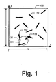
- Fig. 1 shows an example authentication object 100 for use as part of a label, such as a certificate of authenticity.
- authentication object 100 typically contains randomly distributed features that are unique and are hard to replicate.
- the example authentication object 100 shown in Fig. 1 is part of a fiber-based certificate of authenticity and contains fibers 110 that are embedded in the object in a random manner. Fibers 110 serve as the randomly distributed features of authentication object 100. Fibers 110 may be incorporated in authentication object 100 by any means. For example, fibers 100 may be sprayed onto authentication object 100. Fibers 100 may also be embedded into authentication object 100 during the manufacturing process.
- fibers 110 are optical fibers capable of transmitting light between their endpoints. Thus, by shedding light on a certain region 120 of authentication object 100, endpoints of fibers 131-133 that have at least one end-point within the lit up region are illuminated.
- authentication object 100 includes ⁇ randomly distributed fibers.
- Authentication object 100 may be scanned at a resolution of L x L pixels.
- Each fiber has a fixed length of R .
- the example authentication object 100 in Fig. 1 contains fibers, it is to be understood that authentication objects with other randomly distributed features may also be used in a certificate of authenticity in a similar manner.
- the randomly distributed features of authentication object 100 may be used in a certificate of authenticity to protect the proof of authenticity of an arbitrary object, such as a product.
- certain hard-to-replicate data about the randomly distributed features of the certificate of authenticity may be digitized, signed with the private key of the issuer, and the signature may be imprinted on the certificate of authenticity in a machine-readable form to validate that the produced instance is authentic.
- Each instance of the certificate of authenticity is associated with an object whose authenticity the issuer wants to vouch.
- verification of authenticity is done by extracting the signed data (data about the randomly distributed features) using the public key of the issuer and verifying that the extracted data matches the data of the associated instance of the certificate of authenticity.
- the adversary needs to either: (i) figure out the private key of the issuer, (ii) devise a manufacturing process that can exactly replicate an already signed instance of the certificate of authenticity, or (iii) misappropriate signed instances of the certificate of authenticity.
- the certificate of authenticity can be used to protect products whose value roughly does not exceed the cost of forging a single certificate of authenticity instance, including the accumulated development of a successful adversarial manufacturing process.
- a goal of a certificate of authenticity system is to ensure the authenticity of products or certain information associated with a product.
- the set of applications is numerous and broad, ranging from software and media (e.g., DVD, CD) anti-piracy to unforgeable coupons and design of tamper-proof hardware. For example, creating a tamper-resistant chip would require coating its package with a certificate of authenticity. Before each usage, the integrity of the certificate of authenticity should be verified in order to verify authenticity of the protected silicon.
- the hardware platforms may include a barcode. Since the capacity of a barcode for low-cost readers is limited to about 3K bits, the message signed by the private key is limited to the same length. Also, since one of the goals of a certificate of authenticity system is to maximize the effort of the adversary who aims at forging a specific instance of the certificate of authenticity, the problem associated with storing in the fixed-length signed message as much as possible information about the unique and randomly distributed features of a fiber-based certificate of authenticity will be discussed. An example analytical model for a fiber-based certificate of authenticity will be provided.
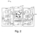
- Fig. 2 is a schematic diagram illustrating an example certificate of authenticity system 200 and example procedures employed by the system for issuing and verifying a certificate of authenticity.
- Certificate of authenticity system 200 includes certificate of authenticity 210, an issuer 230, and a verifier 250.
- certificate of authenticity 210 may include the authentication object 100 in Fig. 1 , a barcode 213, and text 215.
- the information that needs to be protected on a certificate of authenticity includes: ( a ) the representation of the hard-to-replicate randomly distributed features of authentication object 100 and ( b ) an arbitrary associated textual data. Initially, the randomly distributed features of authentication object 100, such as locations of fibers, are scanned using a hardware device. Details on how this information is collected and represented will be discussed below in conjunction with Fig. 3 .
- n F k * nRSA, k ⁇ N
- the digest f of data 231 representing the randomly distributed features of authentication object 100 may statistically maximize the distance between any two distinct certificate of authenticity instances. This goal translates directly to minimized likelihood of a false negative and false positive during the verification step.
- the textual data t is an arbitrary string of characters which depends on the application (e.g., expiration date, manufacturer's warranty).
- the textual data is derived from text 215, which is printed on certificate of authenticity 210 as shown in Fig. 2 .
- the textual data may be hashed using a cryptographically secure hash algorithm 237, such as SHA1.
- the output of the hash function is denoted as a message t with n T bits.
- ⁇ ⁇ ⁇ f ⁇ E t ( f ) of f using t or certain subset of bits from t as a key.
- Message m is signed with an RSA signature 235 using the private-key 233 of the issuer 230.
- Each n RSA bits of m are signed separately.
- This message is encoded and printed as barcode 213 (such as barcodes that obey the PDF417 standard) onto certificate of authenticity 210.
- the verification of certificate of authenticity 210 involves several steps. Verifier 250 initially scans the printed components: text 215 and barcode 213. Barcode 213 is decoded into the originally printed signature s . Text 215 is scanned and is hashed in order to create the message t . Note that generic optical character recognition (OCR) is not required for this task because the font used to print the text is known to the verifier 250 and optimized for improved OCR. For successful certificate of authenticity verification, text 215 and barcode 213 need to be read without errors; a task which is readily achievable with modem scanning technologies.
- OCR optical character recognition
- verifier 250 scans data 251 of representing the randomly distributed features in authentication object 251 and creates their presentation f '. Verifier 250 compares f' to the extracted f . Verifier 250 needs to quantify the correlation between the two sets of data: the one attached to the certificate and the one used to create the signature on the certificate of authenticity. At decision block 259, if the level of similarity of the two sets of data surpasses a certain threshold, verifier 250 announces that the certificate of authenticity 210 is authentic and vice versa.
- Fig. 3A is a schematic diagram of an example scanning system 300 for capturing randomly distributed features of authentication object 310 associated with a certificate of authenticity.
- Scanning system 300 includes optical sensor 322 and light source 324.
- Optical sensor 322 is configured to scan authentication object 310 and may include a charged coupled device (CCD) matrix of a particular resolution. In one embodiment, optical sensor 322 has a resolution of 128 x 128 pixels.
- Light source 324 is configured to provide light of a particular wavelength to illuminate a region of authentication object 310.
- Light source 324 may include, for example, a light emitting diode (LED).
- LED light emitting diode
- Fig. 3B is a top view of the authentication object 310 in Fig. 3A .
- the scanning system 300 divides authentication object 310 into regions, such as regions 311-314.
- regions 311-314 As shown in Fig. 3B , light source 324 of scanning system 300 sheds light onto region 314 while regions 311-313 are isolated from light source 324.
- the location of the endpoints in regions 311-313 of authentication object 310 can be determined by optical sensor 322.
- the read-out of the randomly distributed features in authentication object 310 includes four digital images that contain four different point-sets. Each point-set is associated with a particular region and is determined by illuminating that region.
- scanning system 300 may be configured to prevent this method of forging by changing the wavelength (e.g. color) of the light used by light source 324.
- the wavelength of the light may be randomly selected each time an authentication object is scanned by scanning system 300.
- Optical sensor 322 may be configured to detect the wavelength of the light emitted by the fibers in the authentication object and to determine whether that wavelength corresponds to the wavelength of the light emitted by light source 324. If the wavelengths of the emitted and detected light do not match, the certificate of authenticity is likely a forgery.
- Fig. 4 is a flow diagram of an example process 400 that may be used to create a certificate of authenticity.
- the authentication object in a certificate of authenticity is scanned.
- the authentication object may be scanned using scanning system 300 in Fig. 3A .
- data representing the randomly distributed attributes of the authentication object is determined.
- the data may include the positions of the endpoints of fibers that are illuminated, such as the endpoints shown in Fig. 3B .
- the data is compressing to enhance the security level of the certificate of authenticity.
- Data compression will be discussed in detail in conjunction with Fig. 5 . Briefly stated, a path may be determined for compressing a portion of the data representing randomly distributed attributes in the authentication object.
- the compressed data is encoded.
- the compressed data may be signed using private-key 233 in Fig. 2 .
- the encoded data is incorporated in the certificate of authenticity.
- the encoded data may be printed onto the certificate of authenticity as a barcode, such as barcode 213 in Fig. 2 .
- Fig. 5 is a flow diagram of an example process 500 that may be used to compress data that represents the randomly distributed attributes of an authentication object.
- process 500 will be described in the context of a fiber-based certificate of authenticity. However, process 500 may be applied to any type of certificate of authenticity.
- a probability density function associated with the authentication object is determined. Probability density function will be discussed in Section III-A. An example probability density function is shown in Equation 11. A graphical presentation of the example probability density function is illustrated in Fig. 8 . Briefly stated, the probability density function represents the likelihood that a unit of the randomly distributed attributes is found in a certain location of the authentication object. In the context of a fiber-based certificate of authenticity, the probability density function may represent the probability that a particular point in a region of the authentication object is illuminated. The probability density function may also be used to compute how many of the total fibers will be illuminated in a particular region.
- vectors associated with the randomly distributed attributes are determined.
- point-to-point vectors are used and will be discussed in Section IV-A.
- Equation 16 may be used to compute point-to-point vectors to represent the randomly distributed attributes in a fiber-based certificate of authenticity.
- the vectors are encoded using an arithmetic coding algorithm. Arithmetic coding algorithm will be discussed in Section IV-A. An example algorithm is shown in Table 2.
- a path for compressing a portion of the vectors within a fixed amount of data is determined.
- the method for computing the path is discussed in Section IV-B.
- the example path may be computed using Equation 20.
- the path of the compressed data representing a portion of the randomly distributed attributes is returned.
- An authentication object (L,R,K) is modeled as a square with an edge of L units and K fibers of fixed length R ⁇ Ll2 randomly thrown over the object.
- Other model variants such as variable fiber length or arbitrary shape authentication object, can be derived from this model.
- the authentication object is positioned in the positive quadrant of a 2D Cartesian coordinate system as illustrated in Fig. 1 .
- ⁇ i ⁇ P Pr A ⁇ P
- f A ⁇ B ⁇ S
- B ⁇ S i ⁇ ⁇ Q x ⁇ y ⁇ P ⁇ ⁇ i , Q x ⁇ y ⁇ d ⁇ x ⁇ d ⁇ y .
- the perimeter containment function l( A ) is defined, which measures the length of the part of the perimeter (arc) of the circle centered at A with radius R that is encompassed by the entire authentication object S .
- l( A ) is uniformly computed.
- Fig. 6 is a graphical representation of areas P1-P4 that correspond to the four different regions in an example authentication object 600.
- the perimeter containment function is computed using a closed analytical form distinct for that area using Equations 7-10 as discussed below.
- AREA P1 This is the central area of the authentication object, where for any point Q ⁇ P1, the circle with radius R centered at Q does not intersect with any of the edges of the authentication object.
- ⁇ browses the perimeter of C ( Q , R ) ⁇ S i and a is a constant such that: ⁇ ⁇ Q x ⁇ y ⁇ S - S i ⁇ ⁇ i , Q x ⁇ y ⁇ d ⁇ x ⁇ d ⁇ y 1.
- the probability that A lands on a specific infinitesimally small arc of length d l ⁇ S is equal to d l /l( B ).
- ⁇ i ⁇ Q area ⁇ S - S i - 1 ⁇ ⁇ C Q ⁇ R ⁇ S i ⁇ 4 ⁇ R ⁇ d / d ⁇ ⁇ ⁇ B Q ⁇ R ⁇ ⁇ ⁇ C ⁇ d ⁇ l , where function area( S - S i ) computes the area under S - S i .
- the pdf ⁇ (1, Q ( x , y )) at a point Q ⁇ S - S 1 is proportional to the integral of the inverse of the value of l( ⁇ ) over C ( Q , R ) ⁇ S 1 .
- Figure 7 is a graphical representation of the nineteen different regions on an example authentication object 700 that have distinct analytical formulae as a solution to the integral quantified in Equation 11.
- ⁇ (1, Q ( x , y )) is approximately solved using a simple numerical computation. The results is illustrated in Fig. 8
- Fig. 8 shows that the likelihood that an endpoint of a fiber lands on a certain small area P ⁇ S-S 1 varies significantly depending on the particular position of P within S-S 1 .
- f A ⁇ B , A ⁇ S i .
- Figure 9 is a graphical representation of the areas T0-T8, where ⁇ ( i , Q ( x , y )) is computed using distinct closed analytical forms. ⁇ ( i , Q ( x , y )) is analytically computed based on the analysis of the events ( i-ii ) from Section III-A. Similarly to Section III-A, only in the case when region S 1 is lit up is computed. There are nine different regions in the COA (marked T0 through T8 in Fig. 9 ) where ⁇ (1, Q ) is computed uniformly.
- the analytical closed forms for ⁇ (1, Q ) depending on the location of Q within S 1 are given in Table 1.
- a circle centered at a point A ⁇ S with radius R is denoted as C ( A,R ) .
- C ( A,R ) A circle centered at a point A ⁇ S with radius R.
- the goal of the certificate of authenticity system is to ensure that the task of manufacturing (i.e. forging) a specific authentication object instance as difficult as possible.
- This goal is quantified as a demand for recording the positions of as many as possible fibers of the authentication object.
- the number of regions of authentication object equals four; hence, for each region S i , a quarter n M /4 of bits in the signed message m is dedicated to storing as many as possible fiber end-points illuminated in S - S i once light is shed on S i . Note that in general, not all illuminated points need to be stored; only the largest subset of these points that can be encoded using n M /4 bits.
- An arithmetic coder converts an input stream of arbitrary length into a single rational number within [0,1 ⁇ .
- the principal strength of AC is that it can compress arbitrarily close to the entropy.
- the discussion below shows how a word " aba " is encoded given an alphabet with an unknown pdf of symbol occurrence.
- the example is illustrated in Fig. 10 .
- the AC divides its range into two subranges [0,0.5 ⁇ and [0.5,1 ⁇ , each representing "b” and " a " respectively.
- Symbol a is encoded by constraining the range of the AC to the range that corresponds to this symbol, i.e., [0.5,1 ⁇ .
- the AC divides its range into [0.5,0.6667 ⁇ and [0.6667,1 ⁇ , each representing "b” and " a " respectively.
- the decoder understands the message length either explicitly in the header of the compressed message or via a special " end-of-file " symbol.
- the AC iteratively reduces its operating range up to a point when its range is such that the leading digit of the high and low bound are equal. Then, the leading digit can be transmitted.
- This process called renormalization , enables compression of files of any length on limited precision arithmetic units. Performance improvements of classic AC focus on: using precomputed approximations of arithmetic calculations, replacing division and multiplication with shifting and addition.
- f A ⁇ B K .
- Equation 16 is concluded.
- the encoding of a unit-to-unit vector is done using an AC, which uses algorithm A 1 to assign a corresponding range on the encoding interval for each encoding symbol, i.e. each unit v ⁇ S - S i different from the source unit u .
- algorithm A 1 assigns a range equal to the probability that v is one of the two closest illuminated units with respect to the source unit u . This probability is denoted as p ( v
- u ) can be computed as follows: p v
- u ⁇ u ⁇ w ⁇ M v w 1 - ⁇ w + ⁇ w ⁇ M v w ⁇ u ⁇ ⁇ w ⁇ z ⁇ M v w , z ⁇ w 1 - ⁇ z , where the set of units M v (u) is computed as in algorithm A1.
- Dual vector encoding is used as a primitive to encode a subset of points in the overall compression algorithm presented in the Section IV-B.
- the encoding algorithm is near-optimal for the set of assumptions presented in Section IV-A.2, the same set of constraints is not valid for the overall compression goal, hence, the inherent optimality of using arithmetic coding with range allocation via A 1 is discussed in Section IV-B.
- INSTANCE Directed, complete, and weighted graph G ( N,E ) with a non-negative vertex function ⁇ : E ⁇ R , positive integer l min ⁇ Z + , positive real number ⁇ R + .
- Problem 2 models the optimization problem of compressing as many as possible (i.e. l ) fiber end-points in an authentication object using a fixed storage (i.e. A).
- This problem is NP-complete as it can be shown that the ASYMMETRIC TRAVELING SALESMAN PROBLEM, ATSP, can be reduced to CPS, ATSP ⁇ CPS m p , via binary search for A.
- an efficient constructive heuristic A2 is presented that aims at solving this problem.
- the premier design requirement for the heuristic is fast run-time performance because each certificate of authenticity must be signed separately at a manufacturing line.
- the distance measure between two nodes in N does not obey the triangle inequality for all nodes.
- the encoding procedure from Section IV-A encodes vectors in S - S i using a number of bits proportional to the likelihood that a certain unit is one of the two closest illuminated points. Hence, units farther from the source node are encoded with significantly longer codewords as they are unlikely to occur, which renders shortcuts to these nodes in the solution route highly undesirable.
- Theorem 2 The distance measure w does not universally obey the triangle inequality: ⁇ e u ⁇ v + ⁇ ( e v ⁇ w ⁇ ⁇ u ⁇ w .
- the developed heuristic A2 has two stages: a constructive and an iterative improvement phase.
- the constructive phase follows a greedy heuristic which builds the initial solution.
- A2 identifies a set of dominating edges E' .
- For each pair of edges, e ( u , v ), e( v , u ), between nodes u , v , A2 selects only the shorter of the two and stores it in E' .
- a set P of initial subpaths is created by sorting the edges in E' and selecting the top K shortest edges whose weights sum up as close as possible to A.
- the first and last node in a path p i are denoted as s i and d i respectively.
- 1, the optimal solution is found and the search is stopped. Else, all single-edge subpaths are removed from P .
- the shortest paths are routed via nodes which are not in P .
- the shortest path is denoted between s i and d j as q ( i,j ) .
- A2 sorts all concatenations p i
- A2 continues concatenating subpaths in P via nodes in N - P until the total number of remaining paths is
- the remaining paths are concatenated using an exact algorithm which finds a path p h with the optimal metric: maximal cardinality and a sum of weights smaller than A.
- a rerouting procedure browses all the nodes in P , and using the Dijkstra algorithm tries to find shortest paths to other nodes in P via the remaining nodes in E. The same procedure also tries to find a better ending tail than the one that exists in p h . For each reroute, A2 checks whether the new reroute has a better metric than the current, best path p h .
- A2 contracts the currently best found path p best into p h , so that
- the contraction parameter ⁇ is randomly selected in each iteration within ⁇ ⁇ ⁇ 0.4,0.8 ⁇ .
- Nodes n 0 and n are denoted as the first and last node in p h . While the sum of weights in p h is smaller than ⁇ , among edges that have n 0 or n l as destination or source respectively, we find an edge e with minimal weight and concatenate it to p h .
- A2 performs the rerouting procedure previously described.
- the worst-time complexity of A2 is O (
- the complexity of A2 can be reduced to O (
- the graph is originally complete, by removing edges with high weights, we create a sparse graph, where Johnson's algorithm for all-pairs shortest paths yields O (
- FIG. 11 illustrates a solution to a single instance of the problem, an authentication object (512,0.4 ⁇ 512,256).
- the scanning grid to L 512 scanning cells.
- the figure depicts the case when the lower left quadrant of the authentication object is illuminated.
- the compression ratio is defined as a ratio of the size of the compressed message vs. the original message size.
- a goal of the certificate of authenticity designer is to maximize the cost of forgery ⁇ f using a bounded manufacturing cost ⁇ m .
- ⁇ m Several parameters may impact ⁇ m . For brevity and simplicity, three parameters are discussed:
- the certificate of authenticity issuer and verifier repeat their parts of the algorithm A3 for each authentication object quadrant S i .
- the issuer initially scans the authentication object instance and collects information about the set of points N which illuminate when S i is lit up. Next, using the available A bits, it compresses the largest subset P ⁇ N ,
- G returned by A2. Then, A3 finds a subset U ⁇ S - S i , such that the Euclidean distance between each unit u i ⁇ U and its closest unit p j ⁇ P is at most ⁇ 1 . Subset U of units represents an ⁇ 1 -neighborhood of P. Then, the issuer counts the number K T of points in N that exist in U .
- the verifier extracts from the attached signature the compressed point subset P and ⁇ 2 and recreates the corresponding ⁇ 1 -neighborhood, U .
- the verifier scans the authentication object instance for the set of illuminated fibers N' when S t is lit up. It announces that the instance is authentic by checking that the number of common points in U and N' is at most G + ⁇ 2 and that the number of common points in N ' and P is at least G ⁇ .
- the adversary's goal is to place at least G ⁇ fiber end-points from P accurately, hence, the adversary can afford G (1- ⁇ )+ ⁇ 2 misplacements located in the ⁇ 1 -neighborhood of P during the forgery process. It is expected that each trial, targeting a point p i , if unsuccessful, ends up in the ⁇ 1 -neighborhood of p i .
- the verifier can identify possible misplacements over a larger neighborhood; however, this also increases the expectation for ⁇ 2 - a value that the certificate of authenticity designer wants to keep as low as possible.
- Figure 12 is a graphical representation of a certificate of authenticity design for optimized cost effectiveness.
- the abscissa quantifies fiber length R relative to L , while the ordinate shows the number of fibers K .
- a simple empirical technique may be used that searches for the best fiber cut ⁇ R * , K * ⁇ .
- the search procedure is illustrated using Figure 12 .
- the abscissa and the ordinate represent the values of R and K respectively.
- the bar denotes the expected log-cost of forging an certificate of authenticity instance, log 10 ( ⁇ f ( A 2, RK )).
- the diagram in Figure 12 was computed empirically.
- the expected compression performance for each point in the remaining portion of the ⁇ R , K ⁇ -space was obtained by interpolating the empirical results. From Figure 12 , the best fiber cut can be found in the neighborhood of K * ⁇ 900 and R * ⁇ 0.1 L . This result points to the fact that for the selected design environment, a cross-shaped certificate of authenticity is the best option.
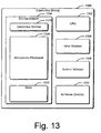
- Fig. 13 illustrates an example computing device 1300 within which the described systems and methods can be either fully or partially implemented.
- Computing device 1300 is only one example of a computing system and is not intended to suggest any limitation as to the scope of the use or functionality of the invention.
- Computing device 1300 can be implemented with numerous other general purpose or special purpose computing system environments or configurations. Examples of well known computing systems, environments, and/or configurations that may be suitable for use include, but are not limited to, personal computers, server computers, thin clients, thick clients, hand-held or laptop devices, multiprocessor systems, microprocessor-based systems, set top boxes, programmable consumer electronics, network PCs, minicomputers, mainframe computers, gaming consoles, distributed computing environments that include any of the above systems or devices, and the like.
- computing device 1300 can include, but are not limited to, processor 1302 (e.g., any of microprocessors, controllers, and the like), system memory 1304, input devices 1306, output devices 1308, and network devices 1310.
- processor 1302 e.g., any of microprocessors, controllers, and the like
- system memory 1304 e.g., any of microprocessors, controllers, and the like
- Computing device 1300 typically includes a variety of computer-readable media. Such media can be any available media that is accessible by computing device 1300 and includes both volatile and non-volatile media, removable and non-removable media.
- System memory 1304 includes computer-readable media in the form of volatile memory, such as random access memory (RAM), and/or non-volatile memory, such as read only memory (ROM).
- RAM random access memory
- ROM read only memory
- BIOS basic input/output system
- System memory 1304 typically contains data and/or program modules that are immediately accessible to and/or presently operated on by processor 1302.
- System memory 1304 can also include other removable/non-removable, volatile/non-volatile computer storage media.
- a hard disk drive may be included for reading from and writing to a non-removable, non-volatile magnetic media;
- a magnetic disk drive may be included for reading from and writing to a removable, non-volatile magnetic disk (e.g., a "floppy disk”);
- an optical disk drive may be included for reading from and/or writing to a removable, non-volatile optical disk such as a CD-ROM, DVD, or any other type of optical media.
- the disk drives and their associated computer-readable media provide non-volatile storage of computer-readable instructions, data structures, program modules, and other data for computing device 1300. It is to be appreciated that other types of computer-readable media which can store data that is accessible by computing device 1300, such as magnetic cassettes or other magnetic storage devices, flash memory cards, CD-ROM, digital versatile disks (DVD) or other optical storage, random access memories (RAM), read only memories (ROM), electrically erasable programmable read-only memory (EEPROM), and the like, can also be utilized to implement exemplary computing device 1300. Any number of program modules can be stored in system memory 1304, including by way of example, an operating system 1320, application programs 1328, and data 1332.
- Computing device 1300 can include a variety of computer-readable media identified as communication media.
- Communication media typically embodies computer-readable instructions, data structures, program modules, or other data in a modulated data signal such as a carrier wave or other transport mechanism and includes any information delivery media.
- modulated data signal refers to a signal that has one or more of its characteristics set or changed in such a manner as to encode information in the signal.
- communication media includes wired media such as a wired network or direct-wired connection, and wireless media such as acoustic, RF, infrared, and other wireless media. Combinations of any of the above are also included within the scope of computer-readable media.
- a user can enter commands and information into computing device 1300 via input devices 1306 such as a keyboard and a pointing device (e.g., a "mouse").
- input devices 1306 such as a keyboard and a pointing device (e.g., a "mouse").
- Other input devices 1306 may include a microphone, joystick, game pad, controller, satellite dish, serial port, scanner, touch screen, touch pads, key pads, and/or the like.
- Output devices 1308 may include a CRT monitor, LCD screen, speakers, printers, and the like.
- Computing device 1300 may include network devices 1310 for connecting to computer networks, such as local area network (LAN), wide area network (WAN), and the like.
- LAN local area network
- WAN wide area network
Landscapes
- Engineering & Computer Science (AREA)
- General Physics & Mathematics (AREA)
- Computer Security & Cryptography (AREA)
- Physics & Mathematics (AREA)
- Theoretical Computer Science (AREA)
- Signal Processing (AREA)
- Computer Networks & Wireless Communication (AREA)
- Multimedia (AREA)
- Architecture (AREA)
- Civil Engineering (AREA)
- Structural Engineering (AREA)
- Computer Vision & Pattern Recognition (AREA)
- Credit Cards Or The Like (AREA)
- Compression, Expansion, Code Conversion, And Decoders (AREA)
- Micro-Organisms Or Cultivation Processes Thereof (AREA)
- Seasonings (AREA)
- Collating Specific Patterns (AREA)
- Storage Device Security (AREA)
- Image Processing (AREA)
- Image Analysis (AREA)
- Air Bags (AREA)
- Geophysics And Detection Of Objects (AREA)
- Train Traffic Observation, Control, And Security (AREA)
- Medicines Containing Material From Animals Or Micro-Organisms (AREA)
Abstract
Description
- The systems and methods described herein generally relate to counterfeit-resistant and/or tamper-resistant labels, and more particularly, to utilizing randomly distributed features of an object (whether embedded or naturally inherent) to limit unauthorized attempts in counterfeiting and/or tampering with the label.
- Counterfeiting and tampering of labels cost product marketers and manufacturers billions of dollars each year in lost income and lost customers. With the proliferation of computer technology, generating labels that resemble the genuine item has become easier. For example, a scanner may be utilized to scan a high-resolution image of a genuine label which can then be reproduced repeatedly at a minimum cost. Also, coupons may be scanned, modified (e.g., to have a higher value), repeatedly printed, and redeemed.
- Various technologies have been utilized to stop the flood of counterfeiting and tampering in the recent years. One way labels have been secured is by incorporation of bar codes. Bar codes are generally machine-readable code that is printed on a label. Using a bar code scanner, the label with a bar code may be quickly read and authenticated. One problem with current bar coded labels is that an identical label may be used on various items.
- Another current solution is to have the scanned bar code examined against secure data stored in a database (e.g., a point of sale (POS) system). This solution, however, requires incorporation of up-to-date data from a marketer or manufacturer. Such a solution requires timely and close cooperation of multiple entities. Also, such a solution limits its implementation flexibility and may not always be feasible.
- These technologies, however, share a common disadvantage; namely, the labels scanned are physically identical for a given product. Accordingly, even though the manufacturing process for creating the legitimate labels may be highly sophisticated, it generally does not take a counterfeiter much time to determine a way to create fake pass-offs. And, once a label is successfully copied a single time, it may be repeatedly reproduced (e.g., by building a master copy that is replicated at low cost). Even if a label is black-listed in a database after a given number of uses, there is no guarantee that the labels that are scanned first are actually the genuine labels.
- Accordingly, the current solutions fail to provide labels that are relatively hard to copy and inexpensive to produce.
- Simmons, G. J., "Identification of data, devices, documents and individuals". Proceedings of the annual international Carnahan conference on security technology, 1991, vol. 25, pages 197 to 218, relates to indirect identification of data, devices, documents and individuals. For example, a verifier is dependent on information provided by the object of the identification and some supplemental information from another source.
- Astrachan, O., "Huffman Coding: A CS2 Assignment", retrieved from http://www.cs.duke.edu/csed/poop/huff/info/, relates to Huffman coding and provides a simple coding example as well as implementing and programming of Huffman coding. A Huffman coding tree is built by using a greedy Huffman algorithm. A table is generated by following every root-to-leaf path while the left/right 0/1 edges which are followed are recorded. For example, the number of times every character of a sequence occurs is counted. These counts are used to create an initial forest of 1-node trees. Each node has a character and a weight equal to the number of times the character occurs.
- It is the object of the invention to provide an improved method and system for creating and verifying counterfeit-resistant and/or tamper-resistant labels.
- This object is solved by the invention as claimed in the independent claims.
- Preferred embodiments are defined by the dependent claims.
- The systems and methods described herein are directed at encoding randomly distributed features in an object. In one aspect, randomly distributed features in an authentication object are determined. Data representing the randomly distributed features is compressed and encoded with a signature. A label is created and includes the authentication object and the encoded data.
- In another aspect, the data is compressed by determining a probability density function associated with the authentication object. Vectors associated with the randomly distributed attributes are determined based, at least in part, on the probability density function. The vectors are encoded using an arithmetic coding algorithm.
-
-
Fig. 1 shows an example authentication object for use as part of a label, such as a certificate of authenticity. -
Fig. 2 is a schematic diagram illustrating an example certificate of authenticity system and example procedures employed by the system for issuing and verifying a certificate of authenticity. -
Fig. 3A is a schematic diagram of an example scanning system for capturing randomly distributed features of an authentication object associated with a certificate of authenticity. -
Fig. 3B is a top view of the authentication object shown inFig. 3A . -
Fig. 4 is a flow diagram of an example process that may be used to create a certificate of authenticity. -
Fig. 5 is a flow diagram of an example process that may be used to compress data that represents the randomly distributed attributes of an authentication object. -
Figure 6 is a graphical representation of areas that correspond to four different regions in an example authentication object. -
Figure 7 is a graphical representation of the nineteen different regions on an example authentication object. -
Fig. 8 is a graph of an example of the probability density function for a square authentication object. -
Figure 9 is a graphical representation of areas in an authentication object. -
Fig. 10 is a graphical representation of an example of how an arithmetic coder encodes the string "aba". -
Figure 11 is an example of an instance of an authentication object shown with nodes. -
Figure 12 is a graphical representation of a certificate of authenticity designed for optimizing cost effectiveness. -
Fig. 13 illustrates an example computing device which the described systems and methods can be either fully or partially implemented. - The systems and methods described herein are directed at encoding information about the randomly distributed features of an object used in a label. Labels may include any type of identification means that are attached to or incorporated within an item. A label that is configured to be authenticated is referred herein as a certificate of authenticity. An object with randomly distributed features used in a certificate of authenticity is referred to herein as an authentication object. To enable self-authentication, a certificate of authenticity may include both the authentication object and the information about the randomly distributed features. A compression method may be used to increase the amount of information about the randomly distributed features that can be encoded and included in the certificate of authenticity. According to one example calculation, the cost of forging a certificate of authenticity is exponentially increased proportional to the improvement in compressing the information. This substantial increase in forging cost results in a reliable certificate of authenticity that is relative cheap to manufacture but is difficult to falsify.
-
Fig. 1 shows anexample authentication object 100 for use as part of a label, such as a certificate of authenticity. To be effectively used in a certificate of authenticity,authentication object 100 typically contains randomly distributed features that are unique and are hard to replicate. Theexample authentication object 100 shown inFig. 1 is part of a fiber-based certificate of authenticity and containsfibers 110 that are embedded in the object in a random manner.Fibers 110 serve as the randomly distributed features ofauthentication object 100.Fibers 110 may be incorporated inauthentication object 100 by any means. For example,fibers 100 may be sprayed ontoauthentication object 100.Fibers 100 may also be embedded intoauthentication object 100 during the manufacturing process. In one embodiment,fibers 110 are optical fibers capable of transmitting light between their endpoints. Thus, by shedding light on acertain region 120 ofauthentication object 100, endpoints of fibers 131-133 that have at least one end-point within the lit up region are illuminated. - In
Fig. 1 ,authentication object 100 includes κ randomly distributed fibers.Authentication object 100 may be scanned at a resolution of L x L pixels. Each fiber has a fixed length of R. Although theexample authentication object 100 inFig. 1 contains fibers, it is to be understood that authentication objects with other randomly distributed features may also be used in a certificate of authenticity in a similar manner. - The randomly distributed features of
authentication object 100 may be used in a certificate of authenticity to protect the proof of authenticity of an arbitrary object, such as a product. For example, certain hard-to-replicate data about the randomly distributed features of the certificate of authenticity may be digitized, signed with the private key of the issuer, and the signature may be imprinted on the certificate of authenticity in a machine-readable form to validate that the produced instance is authentic. Each instance of the certificate of authenticity is associated with an object whose authenticity the issuer wants to vouch. In one embodiment, verification of authenticity is done by extracting the signed data (data about the randomly distributed features) using the public key of the issuer and verifying that the extracted data matches the data of the associated instance of the certificate of authenticity. In order to counterfeit protected objects, the adversary needs to either: (i) figure out the private key of the issuer, (ii) devise a manufacturing process that can exactly replicate an already signed instance of the certificate of authenticity, or (iii) misappropriate signed instances of the certificate of authenticity. From that perspective, the certificate of authenticity can be used to protect products whose value roughly does not exceed the cost of forging a single certificate of authenticity instance, including the accumulated development of a successful adversarial manufacturing process. - A goal of a certificate of authenticity system is to ensure the authenticity of products or certain information associated with a product. The set of applications is numerous and broad, ranging from software and media (e.g., DVD, CD) anti-piracy to unforgeable coupons and design of tamper-proof hardware. For example, creating a tamper-resistant chip would require coating its package with a certificate of authenticity. Before each usage, the integrity of the certificate of authenticity should be verified in order to verify authenticity of the protected silicon.
- Below, example hardware platforms for inexpensive but efficient read-out of the randomly distributed features of a fiber-based certificate of authenticity will be discussed. The hardware platforms may include a barcode. Since the capacity of a barcode for low-cost readers is limited to about 3K bits, the message signed by the private key is limited to the same length. Also, since one of the goals of a certificate of authenticity system is to maximize the effort of the adversary who aims at forging a specific instance of the certificate of authenticity, the problem associated with storing in the fixed-length signed message as much as possible information about the unique and randomly distributed features of a fiber-based certificate of authenticity will be discussed. An example analytical model for a fiber-based certificate of authenticity will be provided. Then, the discussion below will also formalize the problem of compression of a point set, and show that optimal compression of fibers' positions in an instance of a certificate of authenticity is an NP-complete problem. In order to heuristically address this problem, an algorithm which significantly improves upon compression ratios of conventional compression methodologies will be provided.
-
Fig. 2 is a schematic diagram illustrating an example certificate ofauthenticity system 200 and example procedures employed by the system for issuing and verifying a certificate of authenticity. Certificate ofauthenticity system 200 includes certificate ofauthenticity 210, anissuer 230, and averifier 250. As shown inFig. 2 , certificate ofauthenticity 210 may include theauthentication object 100 inFig. 1 , abarcode 213, andtext 215. - The information that needs to be protected on a certificate of authenticity includes: (a) the representation of the hard-to-replicate randomly distributed features of
authentication object 100 and (b) an arbitrary associated textual data. Initially, the randomly distributed features ofauthentication object 100, such as locations of fibers, are scanned using a hardware device. Details on how this information is collected and represented will be discussed below in conjunction withFig. 3 . - For the purpose of discussion, assume that the resulting information f is a random string of nF bits. Parameter nF is fixed and equals nF = k *nRSA, k ∈ N, where nRSA is the length of an RSA public-key (for example, nRSA = 1024) and k is commonly set to k ∈ [1,3]. Given a fixed nF , the digest f of
data 231 representing the randomly distributed features ofauthentication object 100 may statistically maximize the distance between any two distinct certificate of authenticity instances. This goal translates directly to minimized likelihood of a false negative and false positive during the verification step. - The textual data t is an arbitrary string of characters which depends on the application (e.g., expiration date, manufacturer's warranty). The textual data is derived from
text 215, which is printed on certificate ofauthenticity 210 as shown inFig. 2 . - The textual data may be hashed using a cryptographically
secure hash algorithm 237, such as SHA1. The output of the hash function is denoted as a message t with nT bits.Issuer 230 creates the message m that may be signed by RSA. For example, messages f and t are merged into a message m of length nM = nF using a reversible operator Ⓧ̇ that ensures that each bit of m is dependent upon all bits from both f and t. This step may maximize the number of bits that need to be manipulated indata 231 as well astext 215 to create a certain message m. An example of such an operator is symmetric encryption m = t Ⓧ̇ f ≡ Et (f) of f using t or certain subset of bits from t as a key. Message m is signed with anRSA signature 235 using the private-key 233 of theissuer 230. Each nRSA bits of m are signed separately. The resulting signature s has nS = nM = nF bits. This message is encoded and printed as barcode 213 (such as barcodes that obey the PDF417 standard) onto certificate ofauthenticity 210. - The verification of certificate of
authenticity 210 involves several steps.Verifier 250 initially scans the printed components:text 215 andbarcode 213.Barcode 213 is decoded into the originally printed signature s.Text 215 is scanned and is hashed in order to create the message t. Note that generic optical character recognition (OCR) is not required for this task because the font used to print the text is known to theverifier 250 and optimized for improved OCR. For successful certificate of authenticity verification,text 215 andbarcode 213 need to be read without errors; a task which is readily achievable with modem scanning technologies. -
Verifier 250 performs theRSA signature verification 255 on s using issuer's public-key 253 and obtains the signed message m.Verifier 250 can then compute f = m(Ⓧ̇)-1 t. In the example of using encryption as Ⓧ̇, this is achieved via decryption
verifier 250scans data 251 of representing the randomly distributed features inauthentication object 251 and creates their presentation f'.Verifier 250 compares f' to the extracted f.Verifier 250 needs to quantify the correlation between the two sets of data: the one attached to the certificate and the one used to create the signature on the certificate of authenticity. Atdecision block 259, if the level of similarity of the two sets of data surpasses a certain threshold,verifier 250 announces that the certificate ofauthenticity 210 is authentic and vice versa. -
Fig. 3A is a schematic diagram of anexample scanning system 300 for capturing randomly distributed features ofauthentication object 310 associated with a certificate of authenticity.Scanning system 300 includesoptical sensor 322 andlight source 324.Optical sensor 322 is configured to scanauthentication object 310 and may include a charged coupled device (CCD) matrix of a particular resolution. In one embodiment,optical sensor 322 has a resolution of 128 x 128 pixels.Light source 324 is configured to provide light of a particular wavelength to illuminate a region ofauthentication object 310.Light source 324 may include, for example, a light emitting diode (LED). As shown inFig. 3A , one end offiber 326 inauthentication object 310 is illuminated bylight source 324. The light is transmitted to the other end offiber 326 and is sensed byoptical sensor 322. -
Fig. 3B is a top view of theauthentication object 310 inFig. 3A . In operation, thescanning system 300 dividesauthentication object 310 into regions, such as regions 311-314. As shown inFig. 3B ,light source 324 ofscanning system 300 sheds light ontoregion 314 while regions 311-313 are isolated fromlight source 324. By illuminatingregion 314, the location of the endpoints in regions 311-313 ofauthentication object 310 can be determined byoptical sensor 322. Thus, the read-out of the randomly distributed features inauthentication object 310 includes four digital images that contain four different point-sets. Each point-set is associated with a particular region and is determined by illuminating that region. - It is conceivable that advancement in technology, such as nanotechnology, may enable an electronic device to decode the randomly distributed features from a certificate of authenticity and create a light pattern that corresponds to these features. Such a device may be able to forge the certificate of authenticity. In one embodiment,
scanning system 300 may be configured to prevent this method of forging by changing the wavelength (e.g. color) of the light used bylight source 324. For example, the wavelength of the light may be randomly selected each time an authentication object is scanned by scanningsystem 300.Optical sensor 322 may be configured to detect the wavelength of the light emitted by the fibers in the authentication object and to determine whether that wavelength corresponds to the wavelength of the light emitted bylight source 324. If the wavelengths of the emitted and detected light do not match, the certificate of authenticity is likely a forgery. -
Fig. 4 is a flow diagram of anexample process 400 that may be used to create a certificate of authenticity. Atblock 405, the authentication object in a certificate of authenticity is scanned. The authentication object may be scanned usingscanning system 300 inFig. 3A . - At
block 410, data representing the randomly distributed attributes of the authentication object is determined. In a fiber-based authentication object, the data may include the positions of the endpoints of fibers that are illuminated, such as the endpoints shown inFig. 3B . - At
block 415, the data is compressing to enhance the security level of the certificate of authenticity. Data compression will be discussed in detail in conjunction withFig. 5 . Briefly stated, a path may be determined for compressing a portion of the data representing randomly distributed attributes in the authentication object. - At
block 420, the compressed data is encoded. For example, the compressed data may be signed using private-key 233 inFig. 2 . Atblock 425, the encoded data is incorporated in the certificate of authenticity. For example, the encoded data may be printed onto the certificate of authenticity as a barcode, such asbarcode 213 inFig. 2 . -
Fig. 5 is a flow diagram of anexample process 500 that may be used to compress data that represents the randomly distributed attributes of an authentication object. For the purpose of discussion,process 500 will be described in the context of a fiber-based certificate of authenticity. However,process 500 may be applied to any type of certificate of authenticity. - At
block 505, a probability density function associated with the authentication object is determined. Probability density function will be discussed in Section III-A. An example probability density function is shown in Equation 11. A graphical presentation of the example probability density function is illustrated inFig. 8 . Briefly stated, the probability density function represents the likelihood that a unit of the randomly distributed attributes is found in a certain location of the authentication object. In the context of a fiber-based certificate of authenticity, the probability density function may represent the probability that a particular point in a region of the authentication object is illuminated. The probability density function may also be used to compute how many of the total fibers will be illuminated in a particular region. - At
block 510, vectors associated with the randomly distributed attributes are determined. In the context of a fiber-based certificate of authenticity, point-to-point vectors are used and will be discussed in Section IV-A. In particular, Equation 16 may be used to compute point-to-point vectors to represent the randomly distributed attributes in a fiber-based certificate of authenticity. - At
block 515, the vectors are encoded using an arithmetic coding algorithm. Arithmetic coding algorithm will be discussed in Section IV-A. An example algorithm is shown in Table 2. - At
block 520, a path for compressing a portion of the vectors within a fixed amount of data is determined. The method for computing the path is discussed in Section IV-B. The example path may be computed usingEquation 20. Atblock 525, the path of the compressed data representing a portion of the randomly distributed attributes is returned. - In this section, an analytical model of a fiber-based certificate of authenticity is discussed. Two features of a certificate of authenticity S are modeled. Given that a particular region Si of the certificate of authenticity is illuminated, the probability density function that a particular point in S-Si is illuminated is computed. Also, given that K fibers are in S , the expected number of fibers that are illuminated in S-Si is also computed.
- An authentication object (L,R,K) is modeled as a square with an edge of L units and K fibers of fixed length R≤Ll2 randomly thrown over the object. Other model variants, such as variable fiber length or arbitrary shape authentication object, can be derived from this model. The authentication object is positioned in the positive quadrant of a 2D Cartesian coordinate system as illustrated in
Fig. 1 . In addition, the authentication object is divided into four equal squares S = {S 1, S 2, S 3, S 4}. Each of them is used to record the 3D fiber structure as described above in conjunction withFig. 3A and 3B . Next, a fiber is denoted as a tuple f={A,B} of points A,B⊂S such that the distance between them is ∥A-B∥=R. -
Definition 1. Distribution of Illuminated Fiber End-Points. Given that one of the squares Si is illuminated, the probability density function (pdf) ϕ(i,Q(x,y)) is defined for any point Q(x,y)⊂S-Si via the probability ξ(i,P) that any area P⊂S-Si contains an illuminated end-point A of a fiber f={A,B}, conditioned on the fact that the other end-point B is located in the illuminated region St. More formally, for any P⊂S-Si :
- Assume that throwing a fiber f = {A,B} into an authentication object consists of two dependent events: (i) first end-point A lands on the authentication object and (ii) second end-point B hits the authentication object. While A can land anywhere on the COA, the position of B is dependent upon the location of A. Endpoint B must land on part of the perimeter of the circle centered around A, with a radius R , and contained within the authentication object. In the remainder of this subsection, the function ϕ(i,Q(x,y)) is analytically computed based on the analysis of the events (i-ii). For brevity, only ϕ(1,Q(x,y)) is computed for the case when region S t is lit up. ϕ(1,Q(x,y)) are computed in two steps.
-
Definition 2. Perimeter Containment. First, for a given point A⊂S, the perimeter containment function ℓ(A) is defined, which measures the length of the part of the perimeter (arc) of the circle centered at A with radius R that is encompassed by the entire authentication object S. There are four different regions in the authentication object (marked P1 through P4 inFig. 6 ) where ℓ(A) is uniformly computed. -
Fig. 6 is a graphical representation of areas P1-P4 that correspond to the four different regions in anexample authentication object 600. For each point in a certain area Px, the perimeter containment function is computed using a closed analytical form distinct for that area using Equations 7-10 as discussed below. - AREA P1. This is the central area of the authentication object, where for any point Q ⊂ P1, the circle with radius R centered at Q does not intersect with any of the edges of the authentication object. The area is bounded by: R≤x≤L-R, R≤y≤L-R.

- AREA P2. There are four different P2 regions, where a circle with radius R centered at any point Q⊂P2 intersects twice with exactly one edge of the authentication object. For brevity, consideration is give only for the following one: R≤xL-R, 0≤y<R. Equations for other three regions can be symmetrically computed.

- AREA P3. There are four different P3 regions, where a circle with radius R centered at any point Q ⊂ P3 intersects twice with two different edges of the authentication object. Consideration is give only for the following one: 0≤x < R, 0≤y<R, x 2+y 2≥R 2.

- AREA P4. There are four different P4 regions, where a circle with radius R centered at any point Q⊂P4 intersects once with two edges of the COA. Consideration is give only for the following one: x 2 + y 2 < R 2.

- In all Equations 8-10, only the return values of functions arcsin(·) and arccos(·) that are within {0, π/2} are considered.
- In the second step, the actual ϕ(1,Q(x,y)) is computed based on the fact that an illuminated endpoint A of a fiber f ={A,B} is at position A = Q(x,y) only if B is located on the part(s) of the circle C(Q,R) centered at Q(x,y) with a diameter R and contained by S 1.
-
Lemma 3. Dependence of ϕ(i,Q(x,y)) from ℓ(Q(x,y)). Using function ℓ(Q(x,y)), pdf ϕ(i,Q(x,y)) is computed using the following integral:
where ϑ browses the perimeter of C(Q,R) ⊂Si and a is a constant such that:
- A point Q⊂S-Si can be illuminated only due to a fiber f={Q,B}, such that B ⊂ Si . This implicates that B is located somewhere on the perimeter of the circle C(Q, R) contained by Si . For a given fiber f = {A,B}, the probability that A lands on a specific infinitesimally small arc of length dl ⊂ S, is equal to dl/ℓ(B). Hence:

where function area(S-Si ) computes the area under S-Si . Thus, the pdf ϕ(1,Q(x,y)) at a point Q ⊂ S - S 1 is proportional to the integral of the inverse of the value of ℓ(·) over C(Q,R) ⊂ S 1. -
Figure 7 is a graphical representation of the nineteen different regions on an example authentication object 700 that have distinct analytical formulae as a solution to the integral quantified in Equation 11. For brevity, ϕ(1,Q(x,y)) is approximately solved using a simple numerical computation. The results is illustrated inFig. 8 -
Fig. 8 is a graph of an example probability density function for a square authentication object with parameters L = 64 and R = 28 sampled at unit points.Fig. 8 shows that the likelihood that an endpoint of a fiber lands on a certain small area P⊂S-S 1 varies significantly depending on the particular position of P within S-S 1. By using the information about the variance of ϕ(i,Q(x,y)) throughout S-Si , the point-subset compression algorithms can be significantly improved, as presented in Section IV. Manufacturing authentication object such that ϕ(i,Q(x,y)) = const. over the entire area S-S i, is a non-trivial task, probably as difficult as forging an original authentication object.Table 1. Area Bounds ψ(1,Q(x,y)) T0 0≤x≤L/2-R, 0≤y≤L/2-R 0 T1 x 2+(y-L/2)2<R 2, 0≤x≤L/2-R, L/2-R<y≤L/2 
T2 x 2+(y-L/2)2≥R 2, 0≤x ≤L/2-R, L/2-R<y≤L/2 
T3 x 2+(y-L/2)2≥R 2, (x-L/2)2+y 2≥R 2, (x-L/2)2+(y-L/2)2≥R 2 
T4 x 2+(y-L/2)2< R 2, (x-L/2)2+ y 2< R 2, (x-L/2)2+(y-L/2)2≥R 2 

T5 x 2+(y-L/2)2< R 2, (x-L/2)2+ y 2< R 2, (x-L/2)2+ (y-L/2)2< R 2 
T6 x 2+(y-L/2)2<R 2, (x-L/2)2+y 2≥R 2, (x-L/2)2+(y-L/2)2≥R 2, Ll2-R<x≤L/2 
T7 x 2+(y-L/2)2<R 2, (x-L/2)2+y 2≥R 2, (x-L/2)2+(y-L/2)2<R 2 
T8 x 2+(y-L/2)2≥R 2, (x-L/2)2+ y 2≥R 2, (x-L/2)2+(y-L/2)2<R 2 
-
Definition 3. Illumination Ratio of Fiber End-Points. For an authentication object (L,R,K) and its illuminated region Si , the illumination ratio λ is defined as a probability that a fiber f = {A,B} has landed such that one of its end-points is in B⊂S-Si conditioned on the fact that the other end-point is in A⊂Si :
- Definition 4. Possibly Illuminated Arc. For any point A ⊂Si , a function ψ(i,A(x,y)) is defined that measures the length of the part of the perimeter of C(A,R) contained by S-Si .
-
Figure 9 is a graphical representation of the areas T0-T8, where ψ(i,Q(x,y)) is computed using distinct closed analytical forms. ψ(i,Q(x,y)) is analytically computed based on the analysis of the events (i-ii) from Section III-A. Similarly to Section III-A, only in the case when region S 1 is lit up is computed. There are nine different regions in the COA (marked T0 through T8 inFig. 9 ) where ψ(1,Q) is computed uniformly. The analytical closed forms for ψ(1,Q) depending on the location of Q within S 1 are given in Table 1. - Lemma 4. Dependence of ψ(1,Q(x,y)), ℓ(Q(x,y)), and λ. The illumination ratio defined as in Def.3, can be computed as follows:

- A circle centered at a point A ⊂S with radius R is denoted as C(A,R). For each point Q⊂Si , the likelihood that the other end-point B of a fiber f ={Q,B} lands within S-Si , equals the ratio of lengths of parts of the perimeter of C(Q, R) contained by S-Si and S respectively. By integrating this ratio over all points within Si , Equation 15 is obtained.
- Given an authentication object (L,R,K), using λ, computed by numerically approximating Equation 15 and the closed forms for ψ(1,Q) from Table 1, one can compute the expected number of illuminated points in S-S 1 when S 1 is illuminated as λK/2. For example, for an authentication object (64,28,100) the resulting λ ≈ 0.74, which means that on the average, the number of illuminated endpoints in case Si is illuminated, is about 0.74·50 = 37.
- The goal of the certificate of authenticity system is to ensure that the task of manufacturing (i.e. forging) a specific authentication object instance as difficult as possible. This goal is quantified as a demand for recording the positions of as many as possible fibers of the authentication object. In the example compression algorithm, the number of regions of authentication object equals four; hence, for each region Si , a quarter nM /4 of bits in the signed message m is dedicated to storing as many as possible fiber end-points illuminated in S-Si once light is shed on Si . Note that in general, not all illuminated points need to be stored; only the largest subset of these points that can be encoded using nM /4 bits.
- In this section, a mechanism is described, which is configured to encode the distance between two illuminated points in an authentication object. The mechanism is based on arithmetic coding. Next, the problem of compressing as many as possible fiber endpoints using a constant number of bits is formalized. Finally, the discussion will show that this problem is NP-complete and a constructive heuristic as a sub-optimal solution is presented.
- In this subsection, how a vector defined by its starting and ending point is encoded using a near-minimal number of bits is described. An additional constraint is that the points in the considered area occur according to a given pdf.
- An arithmetic coder (AC) converts an input stream of arbitrary length into a single rational number within [0,1}. The principal strength of AC is that it can compress arbitrarily close to the entropy. The discussion below shows how a word "aba" is encoded given an alphabet with an unknown pdf of symbol occurrence.
-
Fig. 10 is a graphical representation of an example of how an arithmetic coder encodes the string "aba" is encoded given an alphabet L = {a,b} with an unknown pdf of symbol occurrence. The example is illustrated inFig. 10 . Initially, the range of the AC is reset to [0,1} and each symbol in L is given an equal likelihood of occurrence Pr[a]= Pr[b]= 1/2. Thus, the AC divides its range into two subranges [0,0.5} and [0.5,1}, each representing "b" and "a" respectively. Symbol a is encoded by constraining the range of the AC to the range that corresponds to this symbol, i.e., [0.5,1}. In addition, the AC updates the counter for the occurrence of symbol "a" and recomputes Pr[a] = 2/3 and Pr[b] =1/3. In the next iteration, according to the updated Pr[a],Pr[b], the AC divides its range into [0.5,0.6667} and [0.6667,1}, each representing "b" and "a" respectively. When "b" arrives next, the AC reduces its range to the corresponding [0.5,0.6667}, updates Pr[a]=Pr[b]=2/4, and divides the new range into [0.5,0.5833} and [0.5833,0.6667}, each representing "b" and "a" respectively. Since the final symbol is "a", the AC encodes this symbol by choosing any number within [0.5833,0.6667} as an output. By choosing a number which encodes with the fewest number of bits (digits in our example), 0.6, the AC creates its final output. The decoder understands the message length either explicitly in the header of the compressed message or via a special "end-of-file" symbol. - The AC iteratively reduces its operating range up to a point when its range is such that the leading digit of the high and low bound are equal. Then, the leading digit can be transmitted. This process, called renormalization, enables compression of files of any length on limited precision arithmetic units. Performance improvements of classic AC focus on: using precomputed approximations of arithmetic calculations, replacing division and multiplication with shifting and addition.
- An AC encodes a sequence of incoming symbols s=s 1,s 2,... using a number of bits equal to source's entropy, H(s)=-Σ s
i Pr[si ]log2(Pr[si ]). Hence, for a semi-infinite stream of independent and identically distributed symbols, on a computer with infinite precision arithmetic, the AC is an optimal, entropy coder. - Given an authentication object (L,R,K), it is assumed that light is shed on one of its quadrants, Si . Next, we assume that the authentication object is partitioned into a grid of L×L unit squares U = u(i,j),i=1...L,j= 1...L, where each u(i,j) covers the square area within x ∈{i-1,i],y∈{j-1,j]. Unit areas model the pixels of the digital scan of an authentication object. The resolution of the scan equals L×L. Next, a principal point of a unit u(x,y) is defined as a point QM with coordinates (x,y).
-
Lemma 5. Unit Illumination Likelihood. Assuming there are κ fibers with exactly one end-point in S-Si , the probability that any unit area u(x,y)⊂ S-S i contains at least one illuminated fiber end-point equals:
And
- From Equation 7, Equation 16 is concluded. In Section III-B, the expectation for κ is E[κ]=λK/2 is computed.
-
Problem 1. Dual Vector Encoding for COA. Conditioned on the fact that unit u ⊂ S-Si contains an illuminated fiber end-point, a goal is to encode using as few as possible bits the locations of two other illuminated units ν1 and ν2 relative to unit u. An additional constraint is that among all illuminated units in S-Si , the principal points of ν1 and ν2, Q 1 and Q 2 respectively, are located at two shortest distances in Euclidean sense from the principal point of u, QM . A priority rule is set so that if a set of units V,|V|>1 are at the same distance with respect to u, the one with the highest likelihood of illumination: argmax v⊂V (τ(ν)) is encoded first.
- The encoding of a unit-to-unit vector is done using an AC, which uses
algorithm A 1 to assign a corresponding range on the encoding interval for each encoding symbol, i.e. each unit v⊂S-Si different from the source unit u. For each unit v,algorithm A 1 assigns a range equal to the probability that v is one of the two closest illuminated units with respect to the source unit u. This probability is denoted as p(v|ν|u). In the case when κ >> 1 units are expected to illuminate in S-Si , p(v|u) can be computed as follows:

where the set of units Mv(u) is computed as in algorithm A1. For each unit v, algorithm A1 assigns a range γ(v,u) used by the AC to encode v conditioned on the fact that u has already been encoded. This range is equal to:
- Thus, the two nearest illuminated units are encoded by construction near-optimally (e.g. the encoding is optimal on a processor with infinite precision arithmetic) because a sequence of symbols is encoded using a number of bits approximately equal to the entropy of the source:

- Dual vector encoding is used as a primitive to encode a subset of points in the overall compression algorithm presented in the Section IV-B. Although the encoding algorithm is near-optimal for the set of assumptions presented in Section IV-A.2, the same set of constraints is not valid for the overall compression goal, hence, the inherent optimality of using arithmetic coding with range allocation via
A 1 is discussed in Section IV-B. - The optimization problem of compressing the positions of as many as possible illuminated unit areas using a fixed number of bits is modeled. Consider the following directed complete graph with weighted edges. For each illuminated unit u⊂S-Si, a node nM is created. A directed edge e(u, v) from node nM to node nv is weighted with the optimal length of the codeword that encodes the vector that points to v, ω(e(u,v))=-log2[γ(v,u)] as in Equation 19, conditioned on the fact that u is already encoded. Lets denote this graph as G(N,E,Ω), where N, E, and Ω represent the set of nodes, directed edges, and corresponding weights respectively.
- INSTANCE: Directed, complete, and weighted graph G(N,E) with a non-negative vertex function Ω:E→R, positive integer lmin ∈Z +, positive real number ∧∈R +.
- QUESTION: Is there a subset of l > lmin nodes N*c N with a path through them, i.e. a permutation


-
Problem 2 models the optimization problem of compressing as many as possible (i.e. l) fiber end-points in an authentication object using a fixed storage (i.e. A). This problem is NP-complete as it can be shown that the ASYMMETRIC TRAVELING SALESMAN PROBLEM, ATSP, can be reduced to CPS,
- First, the distance measure between two nodes in N does not obey the triangle inequality for all nodes. Intuitively, the encoding procedure from Section IV-A encodes vectors in S-Si using a number of bits proportional to the likelihood that a certain unit is one of the two closest illuminated points. Hence, units farther from the source node are encoded with significantly longer codewords as they are unlikely to occur, which renders shortcuts to these nodes in the solution route highly undesirable.
-
Theorem 2. The distance measure w does not universally obey the triangle inequality:
- For simplicity, assume that (∀u⊂S-Si )t=τ(u)=const., then u, v, and w are positioned along the same line in S-Si . The Euclidean distances ∥u-v∥, ∥v-w∥, and ∥u-w∥ are a, b, and a+b respectively. The triangle inequality implies that f(u,v,w)=log2[γ(w,u)]-log2[γ(v,u)]-log2[γ(w,v)]≥0. From Equations 17 and 18, the following can be computed:

and show that for abπt >> 1, the triangle inequality does not hold, i.e., f(a,b,t)< 0. - The best approximation algorithm for ATSP where the triangle inequality holds, yields solutions at most log(|N|) times worse than the optimal. Alternatively, to the best knowledge of the authors, approximation algorithms for ATSP variants where the triangle inequality does not hold, have not been developed. In the general case, when the distance metric function ω is arbitrary, the ATSP problem is NPO-complete, i.e. there is no good approximation algorithm unless P=NP. On the other hand, approximation algorithms for variants of TSP which satisfy a scaled version of the triangle inequality: µ(ω(e(u,v))+ω(e(v,w)))≥ω(u,w),µ> 1 can be solved with a worst case result (3µ + 1)µ/2 times worse than the optimal solution. Distance metric ω does not follow this constraint, hence, a heuristic for
Problem 2 is developed without a worst-case guarantee. In addition, we aim for as good as possible performance of the heuristic on the average, rather than a worst-case guarantee. Authentication object instance which cannot be compressed satisfactorily can be disposed. Likelihood of this event should be small, less than one in a million.

- The rationale behind using the distance metric ω from Section IV-A is based on an assumption that a good solution succeeds to traverse each node on its route via the two closest neighboring nodes. Hence, in the scope of
Problem 2, the used metric is optimal only if the best solution found satisfies this property. If the final solution does not have this property, the optimality of encoding a single vector is dependent upon the distribution of weights of the edges in the solution. - The developed heuristic A2 has two stages: a constructive and an iterative improvement phase. The constructive phase follows a greedy heuristic which builds the initial solution. Initially, A2 identifies a set of dominating edges E'. For each pair of edges, e(u,v), e(v,u), between nodes u,v, A2 selects only the shorter of the two and stores it in E'. Next, a set P of initial subpaths is created by sorting the edges in E' and selecting the top K shortest edges whose weights sum up as close as possible to A. The first and last node in a path pi are denoted as si and di respectively. In the next step, A2 concatenates subpaths from P iteratively in the increasing order of their weights: at any point, the pair of shortest subpaths pi ,pj which have a common source-destination node di = sj , is concatenated until all possible connections are established. In the unlikely case when |P|=1, the optimal solution is found and the search is stopped. Else, all single-edge subpaths are removed from P. Then, using Dijkstra's algorithm, A2 finds all shortest paths between each destination tail di of each subpath pi in P and source tails of all other subpaths, sj ,i=1...|P|,i≠j. The shortest paths are routed via nodes which are not in P. The shortest path is denoted between si and dj as q(i,j). In another greedy step, A2 sorts all concatenations pi |q(i,j)|pj according to their weight/node count ratio. In increasing order of this metric, A2 continues concatenating subpaths in P via nodes in N - P until the total number of remaining paths is |P|=maxP (usually maxP=9). The remaining paths are concatenated using an exact algorithm which finds a path ph with the optimal metric: maximal cardinality and a sum of weights smaller than A. In the final step, a rerouting procedure browses all the nodes in P, and using the Dijkstra algorithm tries to find shortest paths to other nodes in P via the remaining nodes in E. The same procedure also tries to find a better ending tail than the one that exists in ph . For each reroute, A2 checks whether the new reroute has a better metric than the current, best path ph .
-
Figure 11 is an example of an instance of an authentication object (512,0.4·512,256) is shown with κ=88 nodes. A2 returned the path illustrated with bold lines. The path is such that its sum of weights is smaller than Λ =512. To document the path, 12.11 bits per point is used. - In the iterative improvement phase, we repeat several rounds of the following loop. In the first step, A2 contracts the currently best found path p best into ph , so that |ph | is maximal and the sum of weights along ph is smaller than a fraction of ρΛ. The contraction parameter ρ is randomly selected in each iteration within ρ ∈ {0.4,0.8}. Nodes n 0 and n, are denoted as the first and last node in ph . While the sum of weights in ph is smaller than Λ, among edges that have n 0 or nl as destination or source respectively, we find an edge e with minimal weight and concatenate it to ph . When the new candidate path ph is created, it is adopted as the best solution if its metric is better than the metric of the best path created so far. As a last step of the iterative improvement loop, A2 performs the rerouting procedure previously described.
- In order to fit the run-time of A2 for a particular authentication object (L,R,K) class within one second, the improvement loop is repeated I = {100,10000} times. In general, the worst-time complexity of A2 is O(|N|3log|N|) as multi-source shortest paths are computed via the Dijkstra algorithm. In an implementation that uses the Floyd-Warshall algorithm to compute all pairs shortest paths, the complexity of A2 can be reduced to O(|N|3). Although the graph is originally complete, by removing edges with high weights, we create a sparse graph, where Johnson's algorithm for all-pairs shortest paths yields O(|N|2log|N|+|N∥E|).
- The discussion in this section shows how authentication object (L,R,K) parameters impact the performance of the algorithm A.2.
Figure 11 illustrates a solution to a single instance of the problem, an authentication object (512,0.4·512,256). The scanning grid to L = 512 scanning cells. The figure depicts the case when the lower left quadrant of the authentication object is illuminated. Graph G(N,E), built using the corresponding illuminated fiber end-points, is illustrated with medium bold lines. Only the top ten shortest edges starting from each of the κ=88 nodes in the graph is shown. The resulting path shown in the figure using bold lines, consists of 41 nodes. The sum of weights along path's edges is smaller than the storage limit: Λ = 512 bits. The path is compressed using 12.11 bits per fiber end-point (b/fep). Storing the data without compression would require 41·18= 738 bits, which results in a compression ratio of 0.61. The compression ratio is defined as a ratio of the size of the compressed message vs. the original message size. - A goal of the certificate of authenticity designer is to maximize the cost of forgery ζ f using a bounded manufacturing cost ζ m . Several parameters may impact ζ m . For brevity and simplicity, three parameters are discussed:
- the total length of fiber RK ≤ Φ,
- the scanning tolerance ζ, and
- the barcode storage ∧.
- System performance is optimized by limiting the number of trials available to the adversary for accurate positioning of a sufficient subset of the signed fiber end-points (Section VI-A) and by selecting the system parameters {R* ,K* } so that expected forging cost ζ f (A2) is maximized (Section VI-B).
- Consider a compression scheme C which stores G out of the κ illuminated fiber end-points in a Λ-limited storage. In general, when forging a certificate of authenticity, the adversary can use all κ fibers to try to place at least Gζ of them accurately at their corresponding locations. Cost of forging a certificate of authenticity greatly depends upon the number of available trials. Here, a technique is proposed which aims at reducing the number of adversarial trials, KT , by detecting anomalous distribution of fibers around the signed fiber end-points during verification.


- The certificate of authenticity issuer and verifier repeat their parts of the algorithm A3 for each authentication object quadrant Si . The issuer initially scans the authentication object instance and collects information about the set of points N which illuminate when Si is lit up. Next, using the available A bits, it compresses the largest subset P⊂N, |P|=G returned by A2. Then, A3 finds a subset U⊂S-Si , such that the Euclidean distance between each unit ui ∈U and its closest unit pj ∈P is at most ε1. Subset U of units represents an ε1-neighborhood of P. Then, the issuer counts the number KT of points in N that exist in U. Since, KT has to be greater than G to prevent false negatives, the issuer stores along with P, the difference ε2=KT -G in the message m, which is later signed using the private key of the issuer (see Section II). Using the public key of the issuer, the verifier extracts from the attached signature the compressed point subset P and ε2 and recreates the corresponding ε1-neighborhood, U. Then, the verifier scans the authentication object instance for the set of illuminated fibers N' when St is lit up. It announces that the instance is authentic by checking that the number of common points in U and N' is at most G+ε2 and that the number of common points in N' and P is at least Gξ.
- By storing ε2 in the signature, the adversary is imposed to use at most KT = G +ε2 trials that position fibers in the ε1-neighborhood of P . The adversary's goal is to place at least Gζ fiber end-points from P accurately, hence, the adversary can afford G(1-ξ)+ε2 misplacements located in the ε1-neighborhood of P during the forgery process. It is expected that each trial, targeting a point pi , if unsuccessful, ends up in the ε1-neighborhood of pi . By increasing ε1, the verifier can identify possible misplacements over a larger neighborhood; however, this also increases the expectation for ε2 - a value that the certificate of authenticity designer wants to keep as low as possible.
- Below, an empirical design methodology is shown which adopts a given ε1=const., and then seeks to maximize the main objective ζ f (A2) from the perspective of several certificate of authenticity parameters.
-
Problem 3. A Design Objective for a COA System. For a given compression algorithm A2, fixed RK≤Φξ, ε1, and Λ, find a cut {R *,K* } of the available fiber which maximizes:
where ζ f is the cost of forging a COA instance. -
Figure 12 is a graphical representation of a certificate of authenticity design for optimized cost effectiveness. The abscissa quantifies fiber length R relative to L, while the ordinate shows the number of fibers K. The bar illustrates the log - cost of forgery log10(ζ f (A2,R,K)) with a constraint limit Λ = 512 bits and a set of fixed parameters: ζ = 0.9 , ε1= 8, and v = 0.8. The figure also illustrates the quality of solutions obtained for all cuts of a fixed length fiber RK = Φ =100L. - A simple empirical technique may be used that searches for the best fiber cut {R* ,K* }. The search procedure is illustrated using
Figure 12 . The abscissa and the ordinate represent the values of R and K respectively. The bar denotes the expected log-cost of forging an certificate of authenticity instance, log10(ζ f (A2,RK)). The cost is given with respect to R and K , and for a fixed set of parameters: A = 512, ζ=0.9, ε1= 8, and v = 0.8. The diagram inFigure 12 was computed empirically. A2 is applied to 500 randomly generated certificate of authenticity (512,R,K) instances with each combination of R={0.05L,0.10L,...,0.45L} and K={80,96,...,192,256,384,512,768,1024}. The expected compression performance for each point in the remaining portion of the {R, K}-space was obtained by interpolating the empirical results. FromFigure 12 , the best fiber cut can be found in the neighborhood of K *≈900 and R *≈0.1L. This result points to the fact that for the selected design environment, a cross-shaped certificate of authenticity is the best option. Note that careful selection of the fiber cut resulted in an order of magnitude improvement in the forgery cost with respect to a randomly selected point on RK = Φ. The empirical principles used in this example, can be applied to search for a near-optimal parameter set for different certificate of authenticity environments and manufacturing constraints. -
Fig. 13 illustrates anexample computing device 1300 within which the described systems and methods can be either fully or partially implemented.Computing device 1300 is only one example of a computing system and is not intended to suggest any limitation as to the scope of the use or functionality of the invention. -
Computing device 1300 can be implemented with numerous other general purpose or special purpose computing system environments or configurations. Examples of well known computing systems, environments, and/or configurations that may be suitable for use include, but are not limited to, personal computers, server computers, thin clients, thick clients, hand-held or laptop devices, multiprocessor systems, microprocessor-based systems, set top boxes, programmable consumer electronics, network PCs, minicomputers, mainframe computers, gaming consoles, distributed computing environments that include any of the above systems or devices, and the like. - The components of
computing device 1300 can include, but are not limited to, processor 1302 (e.g., any of microprocessors, controllers, and the like),system memory 1304,input devices 1306,output devices 1308, andnetwork devices 1310. -
Computing device 1300 typically includes a variety of computer-readable media. Such media can be any available media that is accessible bycomputing device 1300 and includes both volatile and non-volatile media, removable and non-removable media.System memory 1304 includes computer-readable media in the form of volatile memory, such as random access memory (RAM), and/or non-volatile memory, such as read only memory (ROM). A basic input/output system (BIOS), containing the basic routines that help to transfer information between elements withincomputing device 1300, such as during start-up, is stored insystem memory 1304.System memory 1304 typically contains data and/or program modules that are immediately accessible to and/or presently operated on byprocessor 1302. -
System memory 1304 can also include other removable/non-removable, volatile/non-volatile computer storage media. By way of example, a hard disk drive may be included for reading from and writing to a non-removable, non-volatile magnetic media; a magnetic disk drive may be included for reading from and writing to a removable, non-volatile magnetic disk (e.g., a "floppy disk"); and an optical disk drive may be included for reading from and/or writing to a removable, non-volatile optical disk such as a CD-ROM, DVD, or any other type of optical media. - The disk drives and their associated computer-readable media provide non-volatile storage of computer-readable instructions, data structures, program modules, and other data for
computing device 1300. It is to be appreciated that other types of computer-readable media which can store data that is accessible bycomputing device 1300, such as magnetic cassettes or other magnetic storage devices, flash memory cards, CD-ROM, digital versatile disks (DVD) or other optical storage, random access memories (RAM), read only memories (ROM), electrically erasable programmable read-only memory (EEPROM), and the like, can also be utilized to implementexemplary computing device 1300. Any number of program modules can be stored insystem memory 1304, including by way of example, anoperating system 1320,application programs 1328, anddata 1332. -
Computing device 1300 can include a variety of computer-readable media identified as communication media. Communication media typically embodies computer-readable instructions, data structures, program modules, or other data in a modulated data signal such as a carrier wave or other transport mechanism and includes any information delivery media. The term "modulated data signal" refers to a signal that has one or more of its characteristics set or changed in such a manner as to encode information in the signal. By way of example, and not limitation, communication media includes wired media such as a wired network or direct-wired connection, and wireless media such as acoustic, RF, infrared, and other wireless media. Combinations of any of the above are also included within the scope of computer-readable media. - A user can enter commands and information into
computing device 1300 viainput devices 1306 such as a keyboard and a pointing device (e.g., a "mouse").Other input devices 1306 may include a microphone, joystick, game pad, controller, satellite dish, serial port, scanner, touch screen, touch pads, key pads, and/or the like.Output devices 1308 may include a CRT monitor, LCD screen, speakers, printers, and the like. -
Computing device 1300 may includenetwork devices 1310 for connecting to computer networks, such as local area network (LAN), wide area network (WAN), and the like. - Although the invention has been described in language specific to structural features and/or methodological steps, it is to be understood that the invention defined in the appended claims is not necessarily limited to the specific features or steps described. Rather, the specific features and steps are disclosed as preferred forms of implementing the claimed invention.
Claims (24)
- A method comprising:determining (410) randomly distributed features in an authentication object (100);compressing (415) data representing the randomly distributed features, wherein the compressing comprises:determining (505) a probability density function associated with the authentication object wherein the probability density function represents the probability that a unit of the randomly distributed features is found in a particular region of the authentication object;determining (510) point-to-point vectors associated with end-points of the randomly distributed features based, at least in part, on the probability density function; andencoding (515) the point-to-point vectors using an arithmetic coding algorithm, wherein encoding the vectors using the arithmetic coding algorithm includes determining (520) a path for connecting a portion of the point-to-point vectors within a fixed amount of data wherein the path connects points of the point-to-point vectors;returning (525) the path as the compressed data;encoding (420) the compressed data with a private key; andcreating (425) a label that includes the authentication object and the encoded data.
- The method as recited in Claim 1, wherein the randomly distributed features are fibers (110, 326) that are randomly positioned in the authentication object.
- The method as recited in Claim 2, wherein the probability density function represents a probability that fibers in the particular region are illuminated by a light source (324).
- The method as recited in Claim 2, wherein the probability density function is derived based, at least in part, on the length of the fibers.
- The method as recited in Claim 2, wherein each vector represents the end points of two fibers.
- The method as recited in Claim 1, wherein the label is a certificate of authenticity (210) configured to be self-authenticated and wherein the authentication object is included in the certificate of authenticity.
- The method as recited in Claim 1, wherein the encoded data is included in the label as a barcode.
- The method as recited in Claim 1, further comprising:determining textual data that includes a string of characters, wherein the textual data is included in the label;hashing the textual data with an algorithm; andencrypting the compressed data using the hashed textual data, wherein the hashed textual data is merged with the data representing the randomly distributed features prior to encoding the compressed data.
- The method as recited in Claim 8, wherein the algorithm is a cryptographically secure hash algorithm.
- The method as recited in Claim 8, wherein the algorithm is an SHA1 cryptographical algorithm.
- One or more computer-readable memories containing instructions that are executable by a processor to perform the method recited in Claim 1.
- A system comprising:an issuer (230) configured to determine randomly distributed features (110, 326) in an authentication object (100) and to compress data (231) representing the randomly distributed features, the issuer being further configured to determine a probability density function associated with the authentication object wherein the probability density function represents the probability that a unit of the randomly distributed features is found in a particular region of the authentication object, to determine point-to-point vectors associated with end-points of the randomly distributed features based, at least in part, on the probability density function, to encode the point-to-point vectors by encoding a portion of the point-to-point vectors as a path within a fixed amount of data by applying an arithmetic coding algorithm to compress the data wherein the path connects points of the point-to-point vectors, and to return the path as the compressed data, the issuer being further configured to encode the compressed data with a private key (233) and to create a label (210) that includes the authentication object and the encoded data.
- The system as recited in Claim 12, wherein the issuer is further configured to include a barcode (213) with the encoded data in the label.
- The system as recited in Claim 12, wherein the issuer is further configured to determine textual data (215) that includes a string of characters, the textual data being included in the label, and to hash (237) the textual data with an algorithm.
- The system as recited in Claim 14, wherein the issuer is further configured to encrypt the compressed data using the hashed textual data, wherein the hashed textual data is merged with the data representing the randomly distributed features prior to encoding the compressed data.
- The system as recited in Claim 12, further comprising:a verifier (250) configured to decode the data (251) representing the randomly distributed features in the label and to authenticate the label by comparing (259) the decoded data with the data of the actual randomly distributed features determined from the authentication object.
- A label (210) comprising:an authentication object (100) including randomly distributed features (110, 326); andencoded information (213) associated with the authentication object, the information being encoded with a private key and including compressed data representing the randomly distributed features in the authentication object, wherein the data in the encoded information is compressed by determining a probability density function associated with the authentication object wherein the probability density function represents the probability that a unit of the randomly distributed features is found in a particular region of the authentication object, determining point-to-point vectors associated with end-points of the randomly distributed features based, at least in part, on the probability density function, encoding (515) the point-to-point vectors using an arithmetic coding algorithm, wherein encoding the vectors using the arithmetic coding algorithm includes determining (520) a path for connecting a portion of the point-to-point vectors within a fixed amount of data wherein the path connects points of the point-to-point vectors and returning (525) the path as the compressed data;wherein the label is self-authenticated by comparing (259) a decoding of the encoded information and data (251) representing the randomly distributed features obtained by analyzing the authentication object.
- The label as recited in Claim 17, wherein encoded information is included in the label as a barcode (213).
- The label as recited in Claim 17, further comprising:textual data (215) that includes a string of characters, wherein the compressed data is encrypted using the textual data.
- The label as recited in Claim 19, wherein the compressed data is encrypted by:hashing (237) the textual data with an algorithm; andencrypting (235) the compressed data using the hashed textual data, wherein the hashed textual data is merged with the data representing the randomly distributed features prior to encoding the compressed data.
- An apparatus comprising:means (322) for determining randomly distributed features in an authentication object (100);means (230) for compressing data representing the randomly distributed features, wherein the means for compressing data comprises:means for determining a probability density function associated with the authentication object wherein the probability density function represents the probability that a unit of the randomly distributed features is found in a particular region of the authentication object;means for determining point-to-point vectors associated with end-points of the randomly distributed features based, at least in part, on the probability density function;means for encoding the point-to-point vectors using an arithmetic coding algorithm, wherein encoding the vectors using the arithmetic coding algorithm includes determining a path for connecting a portion of the point-to-point vectors within a fixed amount of data wherein the path connects points of the point-to-point vectors; andmeans for returning the path as the compressed data;means for encoding the compressed data with a private key (233); andmeans for creating a label (210) that includes the authentication object and the encoded data.
- The apparatus as recited in Claim 21, further comprising means for incorporating fibers (110, 326) in the authentication object as the randomly distributed features.
- The apparatus as recited in Claim 21, further comprising:means for determining textual data (215) that includes a string of characters, wherein the textual data is included in the label;means (237) for hashing the textual data with an algorithm; andmeans (235) for encrypting the compressed data using the hashed textual data, the hashed textual data being merged with the data representing the randomly distributed features prior to encoding the compressed data.
- The apparatus as recited in Claim 21, further comprising:means (250) for authenticating the label by comparing (259) encoded data with the data associated with the randomly distributed features in the authentication object.
Applications Claiming Priority (2)
| Application Number | Priority Date | Filing Date | Title |
|---|---|---|---|
| US802981 | 2004-03-17 | ||
| US10/802,981 US7577844B2 (en) | 2004-03-17 | 2004-03-17 | Systems and methods for encoding randomly distributed features in an object |
Publications (3)
| Publication Number | Publication Date |
|---|---|
| EP1577831A2 EP1577831A2 (en) | 2005-09-21 |
| EP1577831A3 EP1577831A3 (en) | 2006-08-09 |
| EP1577831B1 true EP1577831B1 (en) | 2009-03-18 |
Family
ID=34838913
Family Applications (1)
| Application Number | Title | Priority Date | Filing Date |
|---|---|---|---|
| EP05101320A Not-in-force EP1577831B1 (en) | 2004-03-17 | 2005-02-22 | Systems and methods for encoding randomly distributed features in an object |
Country Status (19)
| Country | Link |
|---|---|
| US (1) | US7577844B2 (en) |
| EP (1) | EP1577831B1 (en) |
| JP (1) | JP4718843B2 (en) |
| KR (1) | KR101153016B1 (en) |
| CN (1) | CN1670761B (en) |
| AT (1) | ATE426217T1 (en) |
| AU (1) | AU2005200403B2 (en) |
| BR (1) | BRPI0500133B1 (en) |
| CA (1) | CA2497108C (en) |
| DE (1) | DE602005013318D1 (en) |
| HK (1) | HK1082084A1 (en) |
| MX (1) | MXPA05001925A (en) |
| MY (1) | MY143631A (en) |
| NO (1) | NO20050284L (en) |
| NZ (1) | NZ538305A (en) |
| RU (1) | RU2386168C2 (en) |
| SG (1) | SG115726A1 (en) |
| TW (1) | TWI360782B (en) |
| ZA (1) | ZA200501336B (en) |
Families Citing this family (54)
| Publication number | Priority date | Publication date | Assignee | Title |
|---|---|---|---|---|
| US7162035B1 (en) | 2000-05-24 | 2007-01-09 | Tracer Detection Technology Corp. | Authentication method and system |
| US7089420B1 (en) * | 2000-05-24 | 2006-08-08 | Tracer Detection Technology Corp. | Authentication method and system |
| US8171567B1 (en) | 2002-09-04 | 2012-05-01 | Tracer Detection Technology Corp. | Authentication method and system |
| FR2866139B1 (en) * | 2004-02-06 | 2006-04-14 | Yann Boutant | METHOD FOR PROTECTING THE DIRECT READING OF SENSITIVE INFORMATION, A CARRIER CARRIED WITH SUCH PROTECTED INFORMATION AND A METHOD OF READING THE PROTECTED INFORMATION |
| ATE433164T1 (en) | 2004-03-12 | 2009-06-15 | Ingenia Technology Ltd | METHOD AND DEVICES FOR GENERATING AUTHENTICABLE ITEMS AND THEIR SUBSEQUENT VERIFICATION |
| EP2128790A3 (en) | 2004-03-12 | 2011-01-26 | Ingenia Technology Limited | Authenticity verification with linearised data |
| GB2417592B (en) * | 2004-08-13 | 2006-07-26 | Ingenia Technology Ltd | Authenticity verification of articles |
| US7856116B2 (en) | 2004-11-09 | 2010-12-21 | Digimarc Corporation | Authenticating identification and security documents |
| WO2007086890A2 (en) * | 2005-03-10 | 2007-08-02 | Genemark Inc. | Method, apparatus, and system for authentication using labels containing nucleotide seouences |
| US20060294583A1 (en) * | 2005-05-11 | 2006-12-28 | Ingenia Holdings (U.K.) Limited | Authenticity Verification |
| RU2417448C2 (en) * | 2005-07-27 | 2011-04-27 | Инджениа Холдингс Лимитед | Authenticity verification |
| WO2007012815A1 (en) * | 2005-07-27 | 2007-02-01 | Ingenia Technology Limited | Authenticity verification |
| CN101263503A (en) * | 2005-09-14 | 2008-09-10 | 皇家飞利浦电子股份有限公司 | Improved device, system and method for determining authenticity of an item |
| FR2894757B1 (en) * | 2005-12-13 | 2008-05-09 | Viaccess Sa | METHOD FOR CONTROLLING ACCESS TO A RUBBER CONTENT |
| EP1969525A1 (en) * | 2005-12-23 | 2008-09-17 | Ingenia Holdings (UK)Limited | Optical authentication |
| GB2434442A (en) * | 2006-01-16 | 2007-07-25 | Ingenia Holdings | Verification of performance attributes of packaged integrated circuits |
| US8224018B2 (en) | 2006-01-23 | 2012-07-17 | Digimarc Corporation | Sensing data from physical objects |
| US7949148B2 (en) | 2006-01-23 | 2011-05-24 | Digimarc Corporation | Object processing employing movement |
| GB2440386A (en) * | 2006-06-12 | 2008-01-30 | Ingenia Technology Ltd | Scanner authentication |
| US8837721B2 (en) * | 2007-03-22 | 2014-09-16 | Microsoft Corporation | Optical DNA based on non-deterministic errors |
| US8788848B2 (en) * | 2007-03-22 | 2014-07-22 | Microsoft Corporation | Optical DNA |
| US7884805B2 (en) * | 2007-04-17 | 2011-02-08 | Sony Ericsson Mobile Communications Ab | Using touches to transfer information between devices |
| US9977721B2 (en) | 2007-12-20 | 2018-05-22 | Netapp, Inc. | Evaluating and predicting computer system performance using kneepoint analysis |
| US8805647B2 (en) * | 2007-12-20 | 2014-08-12 | Netapp, Inc. | Evaluating and predicting computer system performance using kneepoint analysis |
| US7995196B1 (en) | 2008-04-23 | 2011-08-09 | Tracer Detection Technology Corp. | Authentication method and system |
| EP2297668A1 (en) * | 2008-06-27 | 2011-03-23 | Koninklijke Philips Electronics N.V. | Device, system and method for verifying the authenticity integrity and/or physical condition of an item |
| US7991153B1 (en) * | 2008-08-26 | 2011-08-02 | Nanoglyph, LLC | Glyph encryption system and related methods |
| GB2466311B (en) | 2008-12-19 | 2010-11-03 | Ingenia Holdings | Self-calibration of a matching algorithm for determining authenticity |
| GB2466465B (en) * | 2008-12-19 | 2011-02-16 | Ingenia Holdings | Authentication |
| US9135948B2 (en) * | 2009-07-03 | 2015-09-15 | Microsoft Technology Licensing, Llc | Optical medium with added descriptor to reduce counterfeiting |
| EP2315358A1 (en) | 2009-10-09 | 2011-04-27 | Thomson Licensing | Method and device for arithmetic encoding or arithmetic decoding |
| BR112012009446B1 (en) | 2009-10-20 | 2023-03-21 | Fraunhofer-Gesellschaft zur Förderung der angewandten Forschung e.V | DATA STORAGE METHOD AND DEVICE |
| GB2476226B (en) | 2009-11-10 | 2012-03-28 | Ingenia Holdings Ltd | Optimisation |
| PT2524371T (en) | 2010-01-12 | 2017-03-15 | Fraunhofer Ges Forschung | Audio encoder, audio decoder, method for encoding an audio information, method for decoding an audio information and computer program using a hash table describing both significant state values and interval boundaries |
| MD4151C1 (en) * | 2010-01-19 | 2012-09-30 | ШКИЛЁВ Думитру | Method for the application of the individual identification tag and individual identification tag |
| KR20110127812A (en) * | 2010-05-20 | 2011-11-28 | 엘지이노텍 주식회사 | System and method for preventing illegal copy |
| JP5554677B2 (en) * | 2010-10-07 | 2014-07-23 | Kddi株式会社 | VIDEO CONTENT GENERATION SYSTEM, VIDEO CONTENT GENERATION DEVICE, AND COMPUTER PROGRAM |
| US9195810B2 (en) | 2010-12-28 | 2015-11-24 | Microsoft Technology Licensing, Llc | Identifying factorable code |
| JP2013015898A (en) * | 2011-06-30 | 2013-01-24 | Fuji Xerox Co Ltd | Authenticity determination support unit, authenticity determination device, authenticity determination support program and authenticity determination program |
| US20150169928A1 (en) | 2012-03-01 | 2015-06-18 | Sys-Tech Solutions, Inc. | Methods and a system for verifying the identity of a printed item |
| US20150379321A1 (en) | 2012-03-01 | 2015-12-31 | Sys-Tech Solutions, Inc. | Methods and a system for verifying the authenticity of a mark |
| BR112014021578A2 (en) | 2012-03-01 | 2021-05-25 | Sys-Tech Solutions, Inc. | METHOD AND SYSTEM FOR VERIFYING AN IDENTITY OF AN ITEM, AND, COMPUTER-READABLE STORAGE MEDIA |
| US9473303B2 (en) * | 2013-05-23 | 2016-10-18 | Rosemount Inc. | Method and system for product authentication |
| FR3017333B1 (en) * | 2014-02-07 | 2019-06-21 | Advanced Track & Trace | METHOD AND DEVICE FOR SECURING AN OBJECT, METHOD AND DEVICE FOR CONTROLLING THEIR CORRESPONDENT AND SECURE OBJECT |
| US20160188643A1 (en) * | 2014-12-31 | 2016-06-30 | Futurewei Technologies, Inc. | Method and apparatus for scalable sorting of a data set |
| US9940572B2 (en) | 2015-02-17 | 2018-04-10 | Sys-Tech Solutions, Inc. | Methods and a computing device for determining whether a mark is genuine |
| EP3093795A1 (en) * | 2015-05-12 | 2016-11-16 | Nokia Technologies Oy | An apparatus and method for providing identification |
| MX369070B (en) | 2015-06-16 | 2019-10-28 | Sys Tech Solutions Inc | Methods and a computing device for determining whether a mark is genuine. |
| US11552968B2 (en) | 2015-10-28 | 2023-01-10 | Qomplx, Inc. | System and methods for detecting and mitigating golden SAML attacks against federated services |
| US11570204B2 (en) | 2015-10-28 | 2023-01-31 | Qomplx, Inc. | Detecting and mitigating golden ticket attacks within a domain |
| EP3168825A1 (en) * | 2015-11-10 | 2017-05-17 | Alcatel Lucent | A unique identifier module, a system for providing with a unique identification, a related module and related method |
| SG11201807829RA (en) | 2016-03-14 | 2018-10-30 | Sys Tech Solutions Inc | Methods and a computing device for determining whether a mark is genuine |
| GB201803528D0 (en) * | 2018-03-05 | 2018-04-18 | Septillion Tech Limited | Data processing apparatus |
| KR20220082257A (en) | 2020-12-10 | 2022-06-17 | 주식회사 투비유니콘 | A system that analyzes natural language by calculating the recognition rate of natural language using a probability function |
Family Cites Families (38)
| Publication number | Priority date | Publication date | Assignee | Title |
|---|---|---|---|---|
| US4424414A (en) | 1978-05-01 | 1984-01-03 | Board Of Trustees Of The Leland Stanford Junior University | Exponentiation cryptographic apparatus and method |
| US4386233A (en) | 1980-09-29 | 1983-05-31 | Smid Miles E | Crytographic key notarization methods and apparatus |
| EP0085130A1 (en) | 1982-02-02 | 1983-08-10 | Omnet Associates | Method and apparatus for maintaining the privacy of digital messages conveyed by public transmission |
| US4633036A (en) | 1984-05-31 | 1986-12-30 | Martin E. Hellman | Method and apparatus for use in public-key data encryption system |
| NL8502567A (en) | 1985-09-19 | 1987-04-16 | Bekaert Sa Nv | METHOD AND APPARATUS FOR VERIFYING ARTICLES FOR OBJECTS AND OBJECTS SUITABLE FOR THE USE OF THIS METHOD |
| US4881264A (en) | 1987-07-30 | 1989-11-14 | Merkle Ralph C | Digital signature system and method based on a conventional encryption function |
| US5016274A (en) | 1988-11-08 | 1991-05-14 | Silvio Micali | On-line/off-line digital signing |
| US4956863A (en) | 1989-04-17 | 1990-09-11 | Trw Inc. | Cryptographic method and apparatus for public key exchange with authentication |
| JPH0327489A (en) * | 1989-06-23 | 1991-02-05 | Toyo Ink Mfg Co Ltd | Method for testing authenticity of document |
| JPH0330097A (en) * | 1989-06-27 | 1991-02-08 | Matsushita Electric Works Ltd | Photoelectric smoke sensor |
| US5003597A (en) | 1989-12-21 | 1991-03-26 | Xerox Corporation | Method and apparatus for data encryption |
| NL9001368A (en) | 1990-06-15 | 1992-01-02 | Tel Developments B V | SECURITY OF OBJECTS OR DOCUMENTS. |
| JPH05270181A (en) * | 1992-03-24 | 1993-10-19 | Toppan Printing Co Ltd | Card and true or false judging method for card |
| JPH05270178A (en) * | 1992-03-30 | 1993-10-19 | Toppan Printing Co Ltd | Information recording medium and method for true and false judgement thereof and recording method of information thereof |
| US5299262A (en) | 1992-08-13 | 1994-03-29 | The United States Of America As Represented By The United States Department Of Energy | Method for exponentiating in cryptographic systems |
| JP3322729B2 (en) * | 1992-09-25 | 2002-09-09 | 日本発条株式会社 | Method and apparatus for determining authenticity of an object to be detected |
| US5864622A (en) | 1992-11-20 | 1999-01-26 | Pitney Bowes Inc. | Secure identification card and method and apparatus for producing and authenticating same |
| US5388158A (en) * | 1992-11-20 | 1995-02-07 | Pitney Bowes Inc. | Secure document and method and apparatus for producing and authenticating same |
| US5420924A (en) | 1993-04-26 | 1995-05-30 | Pitney Bowes Inc. | Secure identification card and method and apparatus for producing and authenticating same by comparison of a portion of an image to the whole |
| US5384846A (en) | 1993-04-26 | 1995-01-24 | Pitney Bowes Inc. | System and apparatus for controlled production of a secure identification card |
| JPH07156580A (en) * | 1993-12-08 | 1995-06-20 | Nhk Spring Co Ltd | Genuineness-checkable cardlike matter |
| US6035914A (en) * | 1993-10-22 | 2000-03-14 | Martin Marietta Energy Systems Inc. | Counterfeit-resistant materials and a method and apparatus for authenticating materials |
| RU2088971C1 (en) | 1994-01-11 | 1997-08-27 | Юрий Дмитриевич Карякин | Measures for protecting securities against forgery |
| US5469506A (en) | 1994-06-27 | 1995-11-21 | Pitney Bowes Inc. | Apparatus for verifying an identification card and identifying a person by means of a biometric characteristic |
| US6904525B1 (en) | 1997-07-01 | 2005-06-07 | Pitney Bowes Inc. | Method for preventing counterfeiting of articles of manufacture |
| US5974150A (en) * | 1997-09-30 | 1999-10-26 | Tracer Detection Technology Corp. | System and method for authentication of goods |
| JP4035221B2 (en) * | 1998-03-10 | 2008-01-16 | 新生化学工業株式会社 | Structure |
| US6193156B1 (en) | 1998-11-12 | 2001-02-27 | Wenyu Han | Method and apparatus for patterning cards, instruments and documents |
| US6321981B1 (en) | 1998-12-22 | 2001-11-27 | Eastman Kodak Company | Method and apparatus for transaction card security utilizing embedded image data |
| CA2595621C (en) | 1999-02-26 | 2009-07-07 | Canada Post Corporation | Unique identifier bar code on stamps and apparatus and method for monitoring stamp usage with identifier bar codes |
| EP1153373B1 (en) | 1999-12-08 | 2003-05-28 | Valentin Alexandrovich Mischenko | Method and system for authentication of articles |
| US7152047B1 (en) * | 2000-05-24 | 2006-12-19 | Esecure.Biz, Inc. | System and method for production and authentication of original documents |
| US7089420B1 (en) * | 2000-05-24 | 2006-08-08 | Tracer Detection Technology Corp. | Authentication method and system |
| EP1173001A3 (en) | 2000-07-11 | 2004-05-06 | Eastman Kodak Company | Authenticatable image with an embedded image having a discernible physical characteristic |
| JP2003030097A (en) * | 2001-07-19 | 2003-01-31 | Jeecom Japan Corp | Software system outputting data to a plurality of portable telephone sets and personal computers different in basic structures |
| DE10204870B4 (en) | 2002-02-06 | 2018-11-15 | Infineon Technologies Ag | Method for securing counterfeiting of a value carrier, value carrier and method for checking its authenticity |
| US7010167B1 (en) * | 2002-04-30 | 2006-03-07 | The United States Of America As Represented By The National Security Agency | Method of geometric linear discriminant analysis pattern recognition |
| US7519726B2 (en) * | 2003-12-12 | 2009-04-14 | International Business Machines Corporation | Methods, apparatus and computer programs for enhanced access to resources within a network |
-
2004
- 2004-03-17 US US10/802,981 patent/US7577844B2/en not_active Expired - Fee Related
-
2005
- 2005-01-18 NO NO20050284A patent/NO20050284L/en unknown
- 2005-01-20 JP JP2005013317A patent/JP4718843B2/en not_active Expired - Fee Related
- 2005-01-24 BR BRPI0500133A patent/BRPI0500133B1/en not_active IP Right Cessation
- 2005-01-26 KR KR1020050007087A patent/KR101153016B1/en not_active IP Right Cessation
- 2005-01-26 TW TW094102365A patent/TWI360782B/en not_active IP Right Cessation
- 2005-02-01 AU AU2005200403A patent/AU2005200403B2/en not_active Ceased
- 2005-02-01 SG SG200500623A patent/SG115726A1/en unknown
- 2005-02-15 CA CA2497108A patent/CA2497108C/en not_active Expired - Fee Related
- 2005-02-15 ZA ZA200501336A patent/ZA200501336B/en unknown
- 2005-02-16 CN CN2005100094917A patent/CN1670761B/en not_active Expired - Fee Related
- 2005-02-17 NZ NZ538305A patent/NZ538305A/en not_active IP Right Cessation
- 2005-02-17 MY MYPI20050581A patent/MY143631A/en unknown
- 2005-02-17 RU RU2005104394/09A patent/RU2386168C2/en not_active IP Right Cessation
- 2005-02-17 MX MXPA05001925A patent/MXPA05001925A/en active IP Right Grant
- 2005-02-22 DE DE602005013318T patent/DE602005013318D1/en active Active
- 2005-02-22 AT AT05101320T patent/ATE426217T1/en not_active IP Right Cessation
- 2005-02-22 EP EP05101320A patent/EP1577831B1/en not_active Not-in-force
-
2006
- 2006-02-17 HK HK06102098.1A patent/HK1082084A1/en not_active IP Right Cessation
Non-Patent Citations (2)
| Title |
|---|
| ASTRACHAN OWEN L.: "Huffman Coding: A CS2 Assignment", INTERNET CITATION, 4 February 2004 (2004-02-04), XP001152046, Retrieved from the Internet <URL:http://www.cs.duke.edu/csed/poop/huff/info/> [retrieved on 20070802] * |
| MENEZES A.J. ET AL: "HANDBOOK OF APPLIED CRYPTOGRAPHY, PASSAGE", HANDBOOK OF APPLIED CRYPTOGRAPHY, 1 January 1997 (1997-01-01), BOCA RATON, FL, CRC PRESS, USA, pages 352 - 368, XP002302003 * |
Also Published As
| Publication number | Publication date |
|---|---|
| BRPI0500133B1 (en) | 2017-05-23 |
| SG115726A1 (en) | 2005-10-28 |
| RU2005104394A (en) | 2006-07-27 |
| CA2497108C (en) | 2012-06-19 |
| ZA200501336B (en) | 2006-10-25 |
| NZ538305A (en) | 2006-07-28 |
| US7577844B2 (en) | 2009-08-18 |
| US20050210255A1 (en) | 2005-09-22 |
| DE602005013318D1 (en) | 2009-04-30 |
| HK1082084A1 (en) | 2006-05-26 |
| TW200535699A (en) | 2005-11-01 |
| EP1577831A3 (en) | 2006-08-09 |
| AU2005200403B2 (en) | 2010-03-18 |
| MXPA05001925A (en) | 2005-09-21 |
| BRPI0500133A (en) | 2005-11-01 |
| NO20050284L (en) | 2005-09-19 |
| CN1670761A (en) | 2005-09-21 |
| JP4718843B2 (en) | 2011-07-06 |
| TWI360782B (en) | 2012-03-21 |
| ATE426217T1 (en) | 2009-04-15 |
| NO20050284D0 (en) | 2005-01-18 |
| CN1670761B (en) | 2012-03-14 |
| CA2497108A1 (en) | 2005-09-17 |
| EP1577831A2 (en) | 2005-09-21 |
| KR20050093715A (en) | 2005-09-23 |
| MY143631A (en) | 2011-06-15 |
| JP2005269610A (en) | 2005-09-29 |
| KR101153016B1 (en) | 2012-06-04 |
| AU2005200403A1 (en) | 2005-10-06 |
| RU2386168C2 (en) | 2010-04-10 |
Similar Documents
| Publication | Publication Date | Title |
|---|---|---|
| EP1577831B1 (en) | Systems and methods for encoding randomly distributed features in an object | |
| CA2494442C (en) | Counterfeit and tamper resistant labels with randomly occurring features | |
| US20080072063A1 (en) | Method for generating an encryption key using biometrics authentication and restoring the encryption key and personal authentication system | |
| US7188258B1 (en) | Method and apparatus for producing duplication- and imitation-resistant identifying marks on objects, and duplication- and duplication- and imitation-resistant objects | |
| Bulens et al. | How to strongly link data and its medium: the paper case | |
| Chang et al. | Robust extraction of secret bits from minutiae | |
| Kailasanathan et al. | Image authentication surviving acceptable modifications using statistical measures and k-mean segmentation | |
| WO2002039653A2 (en) | Self-authentication of value documents using digital signatures | |
| US20220230187A1 (en) | Authentication of packaged products | |
| US20070177823A1 (en) | Method, systems, and media for identifying whether a machine readable mark may contain sensitive data | |
| Kirovski | Toward an automated verification of certificates of authenticity | |
| US20070088953A1 (en) | Method of preparing a document so that it can be authenticated | |
| Wan et al. | Visual secret sharing scheme with (n, n) threshold for selective secret content based on QR codes | |
| KR102219751B1 (en) | Method for authenticating a normalized pattern based on a block chain with a merkle tree structure and apparatus thereof | |
| US20230259901A1 (en) | Issuing entity and method for issuing electronic coin data sets, and payment system | |
| Erlangga et al. | Increasing Secret Data Hiding Capacity in QR Code Using Subcells | |
| Kirovski | A point-set compression heuristic for fiber-based certificates of authenticity | |
| CN113239368B (en) | QR code encryption and decryption method based on electronic signature | |
| US11928748B1 (en) | Method and apparatus for scannable non-fungible token generation | |
| GOKUL | Secured Public level Data Transfer using Multi-Level QR code | |
| AU2004242534B2 (en) | Counterfeit and tamper resistant labels with randomly occurring features | |
| Arakala et al. | Practical considerations for secure minutiae based templates | |
| Mali et al. | SURVEY ON TWO LEVEL QR CODE FOR PRIVATE MESSAGE SHARING AND DOCUMENT AUTHENTICATION | |
| EA006012B1 (en) | Protection system of authenticity of printed information carrier | |
| JP2011519448A (en) | Code providing method using short message service, code providing device using short message service, device for recognizing code received through short message, and code that can be transmitted through short message |
Legal Events
| Date | Code | Title | Description |
|---|---|---|---|
| PUAI | Public reference made under article 153(3) epc to a published international application that has entered the european phase |
Free format text: ORIGINAL CODE: 0009012 |
|
| AK | Designated contracting states |
Kind code of ref document: A2 Designated state(s): AT BE BG CH CY CZ DE DK EE ES FI FR GB GR HU IE IS IT LI LT LU MC NL PL PT RO SE SI SK TR |
|
| AX | Request for extension of the european patent |
Extension state: AL BA HR LV MK YU |
|
| REG | Reference to a national code |
Ref country code: HK Ref legal event code: DE Ref document number: 1082084 Country of ref document: HK |
|
| PUAL | Search report despatched |
Free format text: ORIGINAL CODE: 0009013 |
|
| AK | Designated contracting states |
Kind code of ref document: A3 Designated state(s): AT BE BG CH CY CZ DE DK EE ES FI FR GB GR HU IE IS IT LI LT LU MC NL PL PT RO SE SI SK TR |
|
| AX | Request for extension of the european patent |
Extension state: AL BA HR LV MK YU |
|
| 17P | Request for examination filed |
Effective date: 20070111 |
|
| 17Q | First examination report despatched |
Effective date: 20070213 |
|
| AKX | Designation fees paid |
Designated state(s): AT BE BG CH CY CZ DE DK EE ES FI FR GB GR HU IE IS IT LI LT LU MC NL PL PT RO SE SI SK TR |
|
| GRAP | Despatch of communication of intention to grant a patent |
Free format text: ORIGINAL CODE: EPIDOSNIGR1 |
|
| GRAS | Grant fee paid |
Free format text: ORIGINAL CODE: EPIDOSNIGR3 |
|
| GRAA | (expected) grant |
Free format text: ORIGINAL CODE: 0009210 |
|
| AK | Designated contracting states |
Kind code of ref document: B1 Designated state(s): AT BE BG CH CY CZ DE DK EE ES FI FR GB GR HU IE IS IT LI LT LU MC NL PL PT RO SE SI SK TR |
|
| REG | Reference to a national code |
Ref country code: GB Ref legal event code: FG4D |
|
| REG | Reference to a national code |
Ref country code: CH Ref legal event code: EP |
|
| REG | Reference to a national code |
Ref country code: IE Ref legal event code: FG4D |
|
| REF | Corresponds to: |
Ref document number: 602005013318 Country of ref document: DE Date of ref document: 20090430 Kind code of ref document: P |
|
| PG25 | Lapsed in a contracting state [announced via postgrant information from national office to epo] |
Ref country code: LT Free format text: LAPSE BECAUSE OF FAILURE TO SUBMIT A TRANSLATION OF THE DESCRIPTION OR TO PAY THE FEE WITHIN THE PRESCRIBED TIME-LIMIT Effective date: 20090318 Ref country code: FI Free format text: LAPSE BECAUSE OF FAILURE TO SUBMIT A TRANSLATION OF THE DESCRIPTION OR TO PAY THE FEE WITHIN THE PRESCRIBED TIME-LIMIT Effective date: 20090318 Ref country code: NL Free format text: LAPSE BECAUSE OF FAILURE TO SUBMIT A TRANSLATION OF THE DESCRIPTION OR TO PAY THE FEE WITHIN THE PRESCRIBED TIME-LIMIT Effective date: 20090318 Ref country code: SI Free format text: LAPSE BECAUSE OF FAILURE TO SUBMIT A TRANSLATION OF THE DESCRIPTION OR TO PAY THE FEE WITHIN THE PRESCRIBED TIME-LIMIT Effective date: 20090318 |
|
| PG25 | Lapsed in a contracting state [announced via postgrant information from national office to epo] |
Ref country code: SE Free format text: LAPSE BECAUSE OF FAILURE TO SUBMIT A TRANSLATION OF THE DESCRIPTION OR TO PAY THE FEE WITHIN THE PRESCRIBED TIME-LIMIT Effective date: 20090618 Ref country code: AT Free format text: LAPSE BECAUSE OF FAILURE TO SUBMIT A TRANSLATION OF THE DESCRIPTION OR TO PAY THE FEE WITHIN THE PRESCRIBED TIME-LIMIT Effective date: 20090318 Ref country code: PL Free format text: LAPSE BECAUSE OF FAILURE TO SUBMIT A TRANSLATION OF THE DESCRIPTION OR TO PAY THE FEE WITHIN THE PRESCRIBED TIME-LIMIT Effective date: 20090318 |
|
| NLV1 | Nl: lapsed or annulled due to failure to fulfill the requirements of art. 29p and 29m of the patents act | ||
| PG25 | Lapsed in a contracting state [announced via postgrant information from national office to epo] |
Ref country code: BE Free format text: LAPSE BECAUSE OF FAILURE TO SUBMIT A TRANSLATION OF THE DESCRIPTION OR TO PAY THE FEE WITHIN THE PRESCRIBED TIME-LIMIT Effective date: 20090318 |
|
| PG25 | Lapsed in a contracting state [announced via postgrant information from national office to epo] |
Ref country code: ES Free format text: LAPSE BECAUSE OF FAILURE TO SUBMIT A TRANSLATION OF THE DESCRIPTION OR TO PAY THE FEE WITHIN THE PRESCRIBED TIME-LIMIT Effective date: 20090629 Ref country code: PT Free format text: LAPSE BECAUSE OF FAILURE TO SUBMIT A TRANSLATION OF THE DESCRIPTION OR TO PAY THE FEE WITHIN THE PRESCRIBED TIME-LIMIT Effective date: 20090826 Ref country code: CZ Free format text: LAPSE BECAUSE OF FAILURE TO SUBMIT A TRANSLATION OF THE DESCRIPTION OR TO PAY THE FEE WITHIN THE PRESCRIBED TIME-LIMIT Effective date: 20090318 Ref country code: EE Free format text: LAPSE BECAUSE OF FAILURE TO SUBMIT A TRANSLATION OF THE DESCRIPTION OR TO PAY THE FEE WITHIN THE PRESCRIBED TIME-LIMIT Effective date: 20090318 |
|
| REG | Reference to a national code |
Ref country code: HK Ref legal event code: GR Ref document number: 1082084 Country of ref document: HK |
|
| PG25 | Lapsed in a contracting state [announced via postgrant information from national office to epo] |
Ref country code: RO Free format text: LAPSE BECAUSE OF FAILURE TO SUBMIT A TRANSLATION OF THE DESCRIPTION OR TO PAY THE FEE WITHIN THE PRESCRIBED TIME-LIMIT Effective date: 20090318 Ref country code: IS Free format text: LAPSE BECAUSE OF FAILURE TO SUBMIT A TRANSLATION OF THE DESCRIPTION OR TO PAY THE FEE WITHIN THE PRESCRIBED TIME-LIMIT Effective date: 20090718 Ref country code: SK Free format text: LAPSE BECAUSE OF FAILURE TO SUBMIT A TRANSLATION OF THE DESCRIPTION OR TO PAY THE FEE WITHIN THE PRESCRIBED TIME-LIMIT Effective date: 20090318 |
|
| PLBE | No opposition filed within time limit |
Free format text: ORIGINAL CODE: 0009261 |
|
| STAA | Information on the status of an ep patent application or granted ep patent |
Free format text: STATUS: NO OPPOSITION FILED WITHIN TIME LIMIT |
|
| PG25 | Lapsed in a contracting state [announced via postgrant information from national office to epo] |
Ref country code: DK Free format text: LAPSE BECAUSE OF FAILURE TO SUBMIT A TRANSLATION OF THE DESCRIPTION OR TO PAY THE FEE WITHIN THE PRESCRIBED TIME-LIMIT Effective date: 20090318 Ref country code: BG Free format text: LAPSE BECAUSE OF FAILURE TO SUBMIT A TRANSLATION OF THE DESCRIPTION OR TO PAY THE FEE WITHIN THE PRESCRIBED TIME-LIMIT Effective date: 20090618 |
|
| 26N | No opposition filed |
Effective date: 20091221 |
|
| REG | Reference to a national code |
Ref country code: CH Ref legal event code: PL |
|
| PG25 | Lapsed in a contracting state [announced via postgrant information from national office to epo] |
Ref country code: LI Free format text: LAPSE BECAUSE OF NON-PAYMENT OF DUE FEES Effective date: 20100228 Ref country code: MC Free format text: LAPSE BECAUSE OF NON-PAYMENT OF DUE FEES Effective date: 20100301 Ref country code: CH Free format text: LAPSE BECAUSE OF NON-PAYMENT OF DUE FEES Effective date: 20100228 Ref country code: GR Free format text: LAPSE BECAUSE OF FAILURE TO SUBMIT A TRANSLATION OF THE DESCRIPTION OR TO PAY THE FEE WITHIN THE PRESCRIBED TIME-LIMIT Effective date: 20090619 |
|
| PG25 | Lapsed in a contracting state [announced via postgrant information from national office to epo] |
Ref country code: IE Free format text: LAPSE BECAUSE OF NON-PAYMENT OF DUE FEES Effective date: 20100222 |
|
| PG25 | Lapsed in a contracting state [announced via postgrant information from national office to epo] |
Ref country code: CY Free format text: LAPSE BECAUSE OF FAILURE TO SUBMIT A TRANSLATION OF THE DESCRIPTION OR TO PAY THE FEE WITHIN THE PRESCRIBED TIME-LIMIT Effective date: 20090318 |
|
| PG25 | Lapsed in a contracting state [announced via postgrant information from national office to epo] |
Ref country code: LU Free format text: LAPSE BECAUSE OF NON-PAYMENT OF DUE FEES Effective date: 20100222 Ref country code: HU Free format text: LAPSE BECAUSE OF FAILURE TO SUBMIT A TRANSLATION OF THE DESCRIPTION OR TO PAY THE FEE WITHIN THE PRESCRIBED TIME-LIMIT Effective date: 20090919 |
|
| PG25 | Lapsed in a contracting state [announced via postgrant information from national office to epo] |
Ref country code: TR Free format text: LAPSE BECAUSE OF FAILURE TO SUBMIT A TRANSLATION OF THE DESCRIPTION OR TO PAY THE FEE WITHIN THE PRESCRIBED TIME-LIMIT Effective date: 20090318 |
|
| REG | Reference to a national code |
Ref country code: DE Ref legal event code: R082 Ref document number: 602005013318 Country of ref document: DE Representative=s name: GRUENECKER, KINKELDEY, STOCKMAIR & SCHWANHAEUS, DE |
|
| REG | Reference to a national code |
Ref country code: GB Ref legal event code: 732E Free format text: REGISTERED BETWEEN 20150108 AND 20150114 |
|
| REG | Reference to a national code |
Ref country code: DE Ref legal event code: R082 Ref document number: 602005013318 Country of ref document: DE Representative=s name: GRUENECKER PATENT- UND RECHTSANWAELTE PARTG MB, DE Effective date: 20150126 Ref country code: DE Ref legal event code: R081 Ref document number: 602005013318 Country of ref document: DE Owner name: MICROSOFT TECHNOLOGY LICENSING, LLC, REDMOND, US Free format text: FORMER OWNER: MICROSOFT CORP., REDMOND, WASH., US Effective date: 20150126 |
|
| REG | Reference to a national code |
Ref country code: FR Ref legal event code: TP Owner name: MICROSOFT TECHNOLOGY LICENSING, LLC, US Effective date: 20150724 |
|
| REG | Reference to a national code |
Ref country code: FR Ref legal event code: PLFP Year of fee payment: 12 |
|
| REG | Reference to a national code |
Ref country code: FR Ref legal event code: PLFP Year of fee payment: 13 |
|
| REG | Reference to a national code |
Ref country code: FR Ref legal event code: PLFP Year of fee payment: 14 |
|
| PGFP | Annual fee paid to national office [announced via postgrant information from national office to epo] |
Ref country code: DE Payment date: 20190212 Year of fee payment: 15 Ref country code: FR Payment date: 20190111 Year of fee payment: 15 Ref country code: IT Payment date: 20190221 Year of fee payment: 15 Ref country code: GB Payment date: 20190220 Year of fee payment: 15 |
|
| REG | Reference to a national code |
Ref country code: DE Ref legal event code: R119 Ref document number: 602005013318 Country of ref document: DE |
|
| GBPC | Gb: european patent ceased through non-payment of renewal fee |
Effective date: 20200222 |
|
| PG25 | Lapsed in a contracting state [announced via postgrant information from national office to epo] |
Ref country code: FR Free format text: LAPSE BECAUSE OF NON-PAYMENT OF DUE FEES Effective date: 20200229 Ref country code: GB Free format text: LAPSE BECAUSE OF NON-PAYMENT OF DUE FEES Effective date: 20200222 Ref country code: DE Free format text: LAPSE BECAUSE OF NON-PAYMENT OF DUE FEES Effective date: 20200901 |
|
| PG25 | Lapsed in a contracting state [announced via postgrant information from national office to epo] |
Ref country code: IT Free format text: LAPSE BECAUSE OF NON-PAYMENT OF DUE FEES Effective date: 20200222 |