EP1575655B1 - Catheter balloon having a surface pattern and method of manufacture - Google Patents
Catheter balloon having a surface pattern and method of manufacture Download PDFInfo
- Publication number
- EP1575655B1 EP1575655B1 EP03783685A EP03783685A EP1575655B1 EP 1575655 B1 EP1575655 B1 EP 1575655B1 EP 03783685 A EP03783685 A EP 03783685A EP 03783685 A EP03783685 A EP 03783685A EP 1575655 B1 EP1575655 B1 EP 1575655B1
- Authority
- EP
- European Patent Office
- Prior art keywords
- catheter
- tubular member
- stent
- medical device
- balloon
- Prior art date
- Legal status (The legal status is an assumption and is not a legal conclusion. Google has not performed a legal analysis and makes no representation as to the accuracy of the status listed.)
- Expired - Lifetime
Links
- 238000000034 method Methods 0.000 title claims abstract description 8
- 238000004519 manufacturing process Methods 0.000 title description 4
- 239000000463 material Substances 0.000 claims abstract description 97
- 238000000576 coating method Methods 0.000 claims abstract description 7
- 239000011248 coating agent Substances 0.000 claims abstract description 6
- 238000007639 printing Methods 0.000 claims abstract description 6
- 238000002508 contact lithography Methods 0.000 claims abstract description 4
- 238000005507 spraying Methods 0.000 claims abstract description 4
- 238000007651 thermal printing Methods 0.000 claims abstract description 4
- 229920001187 thermosetting polymer Polymers 0.000 claims description 11
- 239000002657 fibrous material Substances 0.000 claims description 9
- 239000000945 filler Substances 0.000 claims description 6
- 239000000919 ceramic Substances 0.000 claims description 4
- 230000001788 irregular Effects 0.000 claims 1
- 238000000151 deposition Methods 0.000 description 7
- 239000000203 mixture Substances 0.000 description 6
- 239000000126 substance Substances 0.000 description 5
- 230000008021 deposition Effects 0.000 description 4
- 230000000704 physical effect Effects 0.000 description 4
- OKTJSMMVPCPJKN-UHFFFAOYSA-N Carbon Chemical compound [C] OKTJSMMVPCPJKN-UHFFFAOYSA-N 0.000 description 2
- VYPSYNLAJGMNEJ-UHFFFAOYSA-N Silicium dioxide Chemical compound O=[Si]=O VYPSYNLAJGMNEJ-UHFFFAOYSA-N 0.000 description 2
- PNEYBMLMFCGWSK-UHFFFAOYSA-N aluminium oxide Inorganic materials [O-2].[O-2].[O-2].[Al+3].[Al+3] PNEYBMLMFCGWSK-UHFFFAOYSA-N 0.000 description 2
- 229910052799 carbon Inorganic materials 0.000 description 2
- -1 diphenyl ester Chemical class 0.000 description 2
- 230000014759 maintenance of location Effects 0.000 description 2
- 229910052751 metal Inorganic materials 0.000 description 2
- 239000002184 metal Substances 0.000 description 2
- 239000002121 nanofiber Substances 0.000 description 2
- BASFCYQUMIYNBI-UHFFFAOYSA-N platinum Chemical compound [Pt] BASFCYQUMIYNBI-UHFFFAOYSA-N 0.000 description 2
- 229920005989 resin Polymers 0.000 description 2
- 239000011347 resin Substances 0.000 description 2
- 125000000391 vinyl group Chemical group [H]C([*])=C([H])[H] 0.000 description 2
- CBCKQZAAMUWICA-UHFFFAOYSA-N 1,4-phenylenediamine Chemical compound NC1=CC=C(N)C=C1 CBCKQZAAMUWICA-UHFFFAOYSA-N 0.000 description 1
- UUODQIKUTGWMPT-UHFFFAOYSA-N 2-fluoro-5-(trifluoromethyl)pyridine Chemical compound FC1=CC=C(C(F)(F)F)C=N1 UUODQIKUTGWMPT-UHFFFAOYSA-N 0.000 description 1
- YBRVSVVVWCFQMG-UHFFFAOYSA-N 4,4'-diaminodiphenylmethane Chemical compound C1=CC(N)=CC=C1CC1=CC=C(N)C=C1 YBRVSVVVWCFQMG-UHFFFAOYSA-N 0.000 description 1
- XMWRBQBLMFGWIX-UHFFFAOYSA-N C60 fullerene Chemical class C12=C3C(C4=C56)=C7C8=C5C5=C9C%10=C6C6=C4C1=C1C4=C6C6=C%10C%10=C9C9=C%11C5=C8C5=C8C7=C3C3=C7C2=C1C1=C2C4=C6C4=C%10C6=C9C9=C%11C5=C5C8=C3C3=C7C1=C1C2=C4C6=C2C9=C5C3=C12 XMWRBQBLMFGWIX-UHFFFAOYSA-N 0.000 description 1
- 229920000049 Carbon (fiber) Polymers 0.000 description 1
- 229920001651 Cyanoacrylate Polymers 0.000 description 1
- 239000004593 Epoxy Substances 0.000 description 1
- JOYRKODLDBILNP-UHFFFAOYSA-N Ethyl urethane Chemical compound CCOC(N)=O JOYRKODLDBILNP-UHFFFAOYSA-N 0.000 description 1
- UFWIBTONFRDIAS-UHFFFAOYSA-N Naphthalene Chemical compound C1=CC=CC2=CC=CC=C21 UFWIBTONFRDIAS-UHFFFAOYSA-N 0.000 description 1
- 244000208734 Pisonia aculeata Species 0.000 description 1
- XUIMIQQOPSSXEZ-UHFFFAOYSA-N Silicon Chemical compound [Si] XUIMIQQOPSSXEZ-UHFFFAOYSA-N 0.000 description 1
- BQCADISMDOOEFD-UHFFFAOYSA-N Silver Chemical compound [Ag] BQCADISMDOOEFD-UHFFFAOYSA-N 0.000 description 1
- GWEVSGVZZGPLCZ-UHFFFAOYSA-N Titan oxide Chemical compound O=[Ti]=O GWEVSGVZZGPLCZ-UHFFFAOYSA-N 0.000 description 1
- RTAQQCXQSZGOHL-UHFFFAOYSA-N Titanium Chemical compound [Ti] RTAQQCXQSZGOHL-UHFFFAOYSA-N 0.000 description 1
- 150000004703 alkoxides Chemical class 0.000 description 1
- 125000000746 allylic group Chemical group 0.000 description 1
- 229910052782 aluminium Inorganic materials 0.000 description 1
- XAGFODPZIPBFFR-UHFFFAOYSA-N aluminium Chemical compound [Al] XAGFODPZIPBFFR-UHFFFAOYSA-N 0.000 description 1
- 238000002399 angioplasty Methods 0.000 description 1
- 125000003118 aryl group Chemical group 0.000 description 1
- WPYMKLBDIGXBTP-UHFFFAOYSA-N benzoic acid Chemical compound OC(=O)C1=CC=CC=C1 WPYMKLBDIGXBTP-UHFFFAOYSA-N 0.000 description 1
- 235000010290 biphenyl Nutrition 0.000 description 1
- 239000004305 biphenyl Substances 0.000 description 1
- ZDVYABSQRRRIOJ-UHFFFAOYSA-N boron;iron Chemical compound [Fe]#B ZDVYABSQRRRIOJ-UHFFFAOYSA-N 0.000 description 1
- 239000004917 carbon fiber Substances 0.000 description 1
- NLCKLZIHJQEMCU-UHFFFAOYSA-N cyano prop-2-enoate Chemical class C=CC(=O)OC#N NLCKLZIHJQEMCU-UHFFFAOYSA-N 0.000 description 1
- GUJOJGAPFQRJSV-UHFFFAOYSA-N dialuminum;dioxosilane;oxygen(2-);hydrate Chemical compound O.[O-2].[O-2].[O-2].[Al+3].[Al+3].O=[Si]=O.O=[Si]=O.O=[Si]=O.O=[Si]=O GUJOJGAPFQRJSV-UHFFFAOYSA-N 0.000 description 1
- 150000002148 esters Chemical class 0.000 description 1
- CCGKOQOJPYTBIH-UHFFFAOYSA-N ethenone Chemical compound C=C=O CCGKOQOJPYTBIH-UHFFFAOYSA-N 0.000 description 1
- 239000000835 fiber Substances 0.000 description 1
- 229910003472 fullerene Inorganic materials 0.000 description 1
- 239000000499 gel Substances 0.000 description 1
- 239000003365 glass fiber Substances 0.000 description 1
- PCHJSUWPFVWCPO-UHFFFAOYSA-N gold Chemical compound [Au] PCHJSUWPFVWCPO-UHFFFAOYSA-N 0.000 description 1
- 229910052737 gold Inorganic materials 0.000 description 1
- 239000010931 gold Substances 0.000 description 1
- 150000003949 imides Chemical class 0.000 description 1
- 229940094522 laponite Drugs 0.000 description 1
- 239000007788 liquid Substances 0.000 description 1
- XCOBTUNSZUJCDH-UHFFFAOYSA-B lithium magnesium sodium silicate Chemical compound [Li+].[Li+].[OH-].[OH-].[OH-].[OH-].[OH-].[OH-].[OH-].[OH-].[OH-].[OH-].[OH-].[OH-].[Na+].[Na+].[Mg+2].[Mg+2].[Mg+2].[Mg+2].[Mg+2].[Mg+2].[Mg+2].[Mg+2].[Mg+2].[Mg+2].[Mg+2].[Mg+2].[Mg+2].[Mg+2].[Mg+2].[Mg+2].O1[Si](O2)([O-])O[Si]3([O-])O[Si]1([O-])O[Si]2([O-])O3.O1[Si](O2)([O-])O[Si]3([O-])O[Si]1([O-])O[Si]2([O-])O3.O1[Si](O2)([O-])O[Si]3([O-])O[Si]1([O-])O[Si]2([O-])O3.O1[Si](O2)([O-])O[Si]3([O-])O[Si]1([O-])O[Si]2([O-])O3.O1[Si](O2)([O-])O[Si]3([O-])O[Si]1([O-])O[Si]2([O-])O3.O1[Si](O2)([O-])O[Si]3([O-])O[Si]1([O-])O[Si]2([O-])O3 XCOBTUNSZUJCDH-UHFFFAOYSA-B 0.000 description 1
- 239000006247 magnetic powder Substances 0.000 description 1
- 229910044991 metal oxide Inorganic materials 0.000 description 1
- 150000004706 metal oxides Chemical class 0.000 description 1
- VNWKTOKETHGBQD-UHFFFAOYSA-N methane Chemical compound C VNWKTOKETHGBQD-UHFFFAOYSA-N 0.000 description 1
- 238000012986 modification Methods 0.000 description 1
- 230000004048 modification Effects 0.000 description 1
- 229910052901 montmorillonite Inorganic materials 0.000 description 1
- 239000002114 nanocomposite Substances 0.000 description 1
- 239000002071 nanotube Substances 0.000 description 1
- 239000002070 nanowire Substances 0.000 description 1
- ISWSIDIOOBJBQZ-UHFFFAOYSA-N phenol group Chemical group C1(=CC=CC=C1)O ISWSIDIOOBJBQZ-UHFFFAOYSA-N 0.000 description 1
- FCJSHPDYVMKCHI-UHFFFAOYSA-N phenyl benzoate Chemical compound C=1C=CC=CC=1C(=O)OC1=CC=CC=C1 FCJSHPDYVMKCHI-UHFFFAOYSA-N 0.000 description 1
- ZUOUZKKEUPVFJK-UHFFFAOYSA-N phenylbenzene Natural products C1=CC=CC=C1C1=CC=CC=C1 ZUOUZKKEUPVFJK-UHFFFAOYSA-N 0.000 description 1
- 229920003023 plastic Polymers 0.000 description 1
- 239000004033 plastic Substances 0.000 description 1
- 229910052697 platinum Inorganic materials 0.000 description 1
- 229920001296 polysiloxane Polymers 0.000 description 1
- 239000000843 powder Substances 0.000 description 1
- 230000000135 prohibitive effect Effects 0.000 description 1
- 230000001681 protective effect Effects 0.000 description 1
- 239000011342 resin composition Substances 0.000 description 1
- 150000004760 silicates Chemical class 0.000 description 1
- 229910052710 silicon Inorganic materials 0.000 description 1
- 239000010703 silicon Substances 0.000 description 1
- 239000000377 silicon dioxide Substances 0.000 description 1
- 229910052709 silver Inorganic materials 0.000 description 1
- 239000004332 silver Substances 0.000 description 1
- 125000001174 sulfone group Chemical group 0.000 description 1
- 150000003457 sulfones Chemical class 0.000 description 1
- 238000004381 surface treatment Methods 0.000 description 1
- 239000010936 titanium Substances 0.000 description 1
- 229910052719 titanium Inorganic materials 0.000 description 1
- OGIDPMRJRNCKJF-UHFFFAOYSA-N titanium oxide Inorganic materials [Ti]=O OGIDPMRJRNCKJF-UHFFFAOYSA-N 0.000 description 1
- XSQUKJJJFZCRTK-UHFFFAOYSA-N urea group Chemical group NC(=O)N XSQUKJJJFZCRTK-UHFFFAOYSA-N 0.000 description 1
- 229910052902 vermiculite Inorganic materials 0.000 description 1
- 239000010455 vermiculite Substances 0.000 description 1
- 235000019354 vermiculite Nutrition 0.000 description 1
- 229920001567 vinyl ester resin Polymers 0.000 description 1
- 229920002554 vinyl polymer Polymers 0.000 description 1
Images


Classifications
-
- A—HUMAN NECESSITIES
- A61—MEDICAL OR VETERINARY SCIENCE; HYGIENE
- A61M—DEVICES FOR INTRODUCING MEDIA INTO, OR ONTO, THE BODY; DEVICES FOR TRANSDUCING BODY MEDIA OR FOR TAKING MEDIA FROM THE BODY; DEVICES FOR PRODUCING OR ENDING SLEEP OR STUPOR
- A61M25/00—Catheters; Hollow probes
- A61M25/10—Balloon catheters
- A61M25/104—Balloon catheters used for angioplasty
-
- A—HUMAN NECESSITIES
- A61—MEDICAL OR VETERINARY SCIENCE; HYGIENE
- A61M—DEVICES FOR INTRODUCING MEDIA INTO, OR ONTO, THE BODY; DEVICES FOR TRANSDUCING BODY MEDIA OR FOR TAKING MEDIA FROM THE BODY; DEVICES FOR PRODUCING OR ENDING SLEEP OR STUPOR
- A61M25/00—Catheters; Hollow probes
- A61M25/10—Balloon catheters
- A61M2025/1043—Balloon catheters with special features or adapted for special applications
- A61M2025/1086—Balloon catheters with special features or adapted for special applications having a special balloon surface topography, e.g. pores, protuberances, spikes or grooves
-
- Y—GENERAL TAGGING OF NEW TECHNOLOGICAL DEVELOPMENTS; GENERAL TAGGING OF CROSS-SECTIONAL TECHNOLOGIES SPANNING OVER SEVERAL SECTIONS OF THE IPC; TECHNICAL SUBJECTS COVERED BY FORMER USPC CROSS-REFERENCE ART COLLECTIONS [XRACs] AND DIGESTS
- Y10—TECHNICAL SUBJECTS COVERED BY FORMER USPC
- Y10T—TECHNICAL SUBJECTS COVERED BY FORMER US CLASSIFICATION
- Y10T428/00—Stock material or miscellaneous articles
- Y10T428/13—Hollow or container type article [e.g., tube, vase, etc.]
- Y10T428/1352—Polymer or resin containing [i.e., natural or synthetic]
- Y10T428/1362—Textile, fabric, cloth, or pile containing [e.g., web, net, woven, knitted, mesh, nonwoven, matted, etc.]
-
- Y—GENERAL TAGGING OF NEW TECHNOLOGICAL DEVELOPMENTS; GENERAL TAGGING OF CROSS-SECTIONAL TECHNOLOGIES SPANNING OVER SEVERAL SECTIONS OF THE IPC; TECHNICAL SUBJECTS COVERED BY FORMER USPC CROSS-REFERENCE ART COLLECTIONS [XRACs] AND DIGESTS
- Y10—TECHNICAL SUBJECTS COVERED BY FORMER USPC
- Y10T—TECHNICAL SUBJECTS COVERED BY FORMER US CLASSIFICATION
- Y10T428/00—Stock material or miscellaneous articles
- Y10T428/13—Hollow or container type article [e.g., tube, vase, etc.]
- Y10T428/1352—Polymer or resin containing [i.e., natural or synthetic]
- Y10T428/1369—Fiber or fibers wound around each other or into a self-sustaining shape [e.g., yarn, braid, fibers shaped around a core, etc.]
-
- Y—GENERAL TAGGING OF NEW TECHNOLOGICAL DEVELOPMENTS; GENERAL TAGGING OF CROSS-SECTIONAL TECHNOLOGIES SPANNING OVER SEVERAL SECTIONS OF THE IPC; TECHNICAL SUBJECTS COVERED BY FORMER USPC CROSS-REFERENCE ART COLLECTIONS [XRACs] AND DIGESTS
- Y10—TECHNICAL SUBJECTS COVERED BY FORMER USPC
- Y10T—TECHNICAL SUBJECTS COVERED BY FORMER US CLASSIFICATION
- Y10T428/00—Stock material or miscellaneous articles
- Y10T428/13—Hollow or container type article [e.g., tube, vase, etc.]
- Y10T428/1352—Polymer or resin containing [i.e., natural or synthetic]
- Y10T428/1372—Randomly noninterengaged or randomly contacting fibers, filaments, particles, or flakes
-
- Y—GENERAL TAGGING OF NEW TECHNOLOGICAL DEVELOPMENTS; GENERAL TAGGING OF CROSS-SECTIONAL TECHNOLOGIES SPANNING OVER SEVERAL SECTIONS OF THE IPC; TECHNICAL SUBJECTS COVERED BY FORMER USPC CROSS-REFERENCE ART COLLECTIONS [XRACs] AND DIGESTS
- Y10—TECHNICAL SUBJECTS COVERED BY FORMER USPC
- Y10T—TECHNICAL SUBJECTS COVERED BY FORMER US CLASSIFICATION
- Y10T428/00—Stock material or miscellaneous articles
- Y10T428/13—Hollow or container type article [e.g., tube, vase, etc.]
- Y10T428/1352—Polymer or resin containing [i.e., natural or synthetic]
- Y10T428/139—Open-ended, self-supporting conduit, cylinder, or tube-type article
- Y10T428/1393—Multilayer [continuous layer]
Definitions
- an expandable, implantable medical device such as a stent, stent-graft, graft or vena cava filter
- an expandable, implantable medical device such as a stent is disposed about a balloon which in turn is mounted on a catheter tube.
- the catheter is inserted into a bodily vessel and advanced to a desired location.
- the balloon is then inflated so as to expand or assist in expanding the medical device.
- the catheter may be equipped with a medical device retaining region in addition to or in place of the medical balloon.
- 'catheter' as used herein is directed to medical devices such as guide catheters, delivery catheters, balloon catheters, and portions thereof, including but not limited to inflatable members such as balloons.
- Numerous devices have been employed to help secure an expandable medical device, such as a stent onto a catheter.
- Such devices include pull-back sheathes which extend over the entire stent to retain the stent to a portion of the catheter.
- sheathes may be found in US 5772669 , US 5868755 , US 4732152 , US 4848343 , US 4875480 , US 5662703 , US 5690644 , WO 94/15549 and others.
- Some systems have been developed which avoid the need for retractable sheathes by providing a stent delivery catheter with one or more self-retracting sleeves.
- Some examples of delivery catheters having sleeves which may be self-retractable are described in: US 4950227 , US 5403341 , US 5108416 , and others.
- an inflation expandable stent delivery system includes a sleeve which overlaps the distal or proximal margin (or both) of the stent during delivery. During inflation of the stent at the deployment site, the stent margins are freed of the protective sleeve(s).
- US 5403341 to Solar relates to a stent delivery and deployment assembly which uses retaining sheaths positioned about opposite ends of the compressed stent. The retaining sheaths of Solar are adapted to tear under pressure as the stent is radially expanded, thus releasing the stent from engagement with the sheaths.
- US 5108416 to Ryan et al. describes a stent introducer system which uses one or two flexible end caps and an annular socket surrounding the balloon to position the stent during introduction to the deployment site.
- U.S. Pat. App. 09/697608 includes stent securement hubs which engage portions of a stent disposed about a catheter
- EP 696,447 describes delivery catheters comprising runners for circumferentially supporting a prosthesis.
- Still other systems have been developed which employ surface features on the catheter surface to aid in retaining the stent thereabout.
- Some examples of systems having unique surface features are described in: WO 00/57816 wherein catheters are described having a textured or roughened surface for retaining a medical device thereon, US 6258099 which describes catheter balloons having engagement protrusions, and US 6048350 which describes delivery systems employing a combination of securement hubs and balloon segments to aid in retaining a stent there on.
- An advantage of providing a stent delivery catheter and/or balloon with surface features that promote stent retention prior to delivery is that the profile of the catheter may be minimized as there may be no need to include additional sheathes, sleeves or other members which would otherwise overlap the stent and increase the profile of the catheter.
- Another advantage of providing a catheter with stent retaining surface features is that by removing the need for retractable members, the need for relatively bulky or complex retraction systems is likewise removed, thereby providing a delivery system which may be much more simple and safer to use.
- Expandable medical devices such as stents have a wide variety of shapes, sizes and configurations.
- a stent having a particular strut pattern may have performance characteristics which are significantly different than a stent having a different strut pattern.
- typical manufacturing processes of catheters do not readily lend themselves to individualized production of different catheter types.
- catheters are formed of extruded material which is then shaped or molded into the final catheter shape.
- Providing dozens of different molds for a wide range of surface feature patterns may be cost prohibitive as well as extremely inefficient from a manufacturing perspective.
- it would be desirable to provide a method for applying a unique surface feature pattern to catheters which may be cheaply and easily employed on an individual basis.
- stiffened balloon catheter having longitudinally discontinuous stiffening members connected to the expandable balloon. Projections on the stiffening members may retain a stent or a stent-graft.
- the stiffening members may be formed from various materials including metal, plastic or fiber material.
- the present invention includes many different embodiments. Some of the embodiments are directed to catheters in general and in some embodiments to catheter balloons for angioplasty or advantageously for use in the delivery of medical devices such as stents.
- Some embodiments of the invention are directed to catheters having a textured, partially textured or otherwise marked surface which provides the catheter with improved stent retaining characteristics.
- the texturing or marking facilitates the positioning of an expandable, implantable medical device on the catheter and increases the securement of a stent or other expandable, implantable medical device to the catheter.
- a catheter, balloon or other tubular shaft may be provided with a deposited pattern of material.
- the deposited material may be characterized as any material that may be used to modify the physical properties of the tubing, such as for example flexibility, via the configuration, location, and/or other characteristic of the pattern and the physical properties of the deposited material.
- the material deposited on the catheter or balloon shaft is a fibrous material.
- the material may be, but is not limited to inorganic ceramics.
- the deposited material is provided with a pattern which is constructed and arranged to improve retention and engagement between the catheter and/or balloon surface and a stent or other implantable medical device that may be disposed thereabout.
- the deposited pattern of material is of a material having a different composition than that of the underlying catheter or balloon tubing.
- material deposited on a balloon or catheter is a continuous film.
- the deposited material may be a discontinuous coating or deposit.
- the deposited material may be deposited on the tubing in a pattern comprised of features such as helical, longitudinal, crossed, and/or radial stripes, or any pattern desired.
- the deposited material is oriented on the tubing in one or more longitudinally tapering stripes.
- the surface of the balloon is provided with one or more deposited struts of material which act to provide the balloon with uniform inflation characteristics.
- the strut or struts can act to transfer stress from the ends of the balloon to the middle portion of the balloon.
- material deposited on a catheter or balloon is deposited by one or more techniques including: solution coating, spray coating, thermal printing, piezo jet printing, contact printing, etc.
- the particular method utilized to deposit the material on the catheter/balloon tube may include one or more of the following steps: a curing step or steps, initial surface treatment step or steps, a post-deposition processing step or steps, etc.
- the resulting selectively coated catheter and/or balloon tubular member will be provided with one or more physical characteristics that are different than the tubular member would have had without the deposition of material.
- the tubular member may be provided with a variety of desired performance characteristics. Some examples of characteristics that may be altered or improved according to the present invention include but are not limited to: flexular modulus, elasticity, columnar strength, kink resistance, burst pressure, compliance, among others.
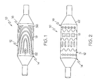
- FIGs. 1 and 2 embodiments of the invention are shown wherein different forms of medical device, such as a catheter 10 are respectively depicted.
- Catheter 10 may be any type of elongate medical device or portion thereof, such as a balloon, capable of being inserted into a body lumen and advanced therethrough. Numerous types and configurations of such medical devices are known and the term "catheter” as used herein is merely a convenient term used to designate all such devices.
- catheter 10 may be manufactured from a catheter material or tube 12.
- the catheter 10 includes a distal region 14 which has an outer surface 16 having a pattern of indented or raised material 18 thereon.
- a deposited material 18 can be characterized as being soft or tacky when compared to the surrounding material 12. However, material 18 that is comparatively hard, relative to the catheter material 12 may also be used. In some embodiments of the invention, the materials 12 and 18 may be the same or have similar characteristics.
- FIGs. 1 and 2 illustrate merely two potential patterns of material 18 which a catheter 10 may be configured with. As is shown in FIG. 3 , such unique patterns are useful in securing an expandable medical device, such as for example a stent 20 to the catheter surface 16 prior to delivery of the stent 20.
- an expandable medical device such as for example a stent 20
- stents may be self-expandable, balloon expandable or maybe a hybrid of the two more common types. Stents of all types may be included with appropriate embodiments of the present invention.
- the distal region 14 of the catheter 10 may be equipped with an expandable member or balloon 22.
- balloon 22 may be used to trigger or aid in stent delivery and may further be used to seat the stent into place within the body lumen.
- the distal region 14 may include a balloon 22 therewith.
- the catheter 10 will further include an inflation means such as an inflation lumen or similar device (not shown) to inflate the balloon 22 for stent delivery or other purposes as is known in the art.
- the material 18 may be characterized as any substance or substances that alter the physical properties of the catheter 10, such as the ability of the catheter surface 16 to interact with a medical device such as stent 20 disposed thereabout.
- the material 18 may provide the catheter 10 with improved ability to removably engage the stent 20 mounted thereon such as is shown in FIGs. 3 and 6 .
- a wide variety of substances may comprise material 18.
- Material 18 may include, but is not limited to: inorganic ceramic substances.
- the material 18 is a fibrous material comprising organic and/or inorganic thermoset compositions.
- organic thermoset compositions may comprise for example: linear or branched resin systems containing epoxy, urethane, imide, ester, ketene, sulphone or urea functionalities.
- Organic thermosets may also contain vinyl or allylic functionalities, such as vinyl esters and cyanoacrylates, for example. Phenolic and silicone containing resins would also be included.
- Inorganic fibrous materials may contain thermoset compositions comprising alkoxides of silicon, aluminum, titanium, zirconcium, etc. In some embodiments carbon fiber may also be used.
- some examples of the invention may include a material 18 that is a thermoset composition comprising mesogenic functionalities which provide liquid crystalline properties to the thermoset.
- material 18 includes resin compositions having planar aromatic functionalities such as: 4-4'-di(2,3 epoxypropyloxy) phenyl benzoate, diamino diphenyl ester, 2,6 napthalene - di[4-(2-propenyloxy) benzoate], diamino diphenly sulfone, methylene dianiline, dicyatonapthalene, resorcinol diglycidyl ether, diaminonapthalene, napthalene diol, and p-phenylene diamine among others.
- fibrous material 18 may contain additional fillers to enhance the properties of the thermoset. These fillers may be conventional fillers such as glass fiber, carbon, etc. In some embodiments the material may contain nanocomposite fillers such as intercalated and /or exfoliated clays such as, for example: montmorillonite, hectorites, hydrotalcites, vermiculite, and laponite.
- filler materials include, for example, monomeric silicates such as polyhedral oligomer silesequioxanes (POSS), carbon and ceramic nanotubes and fibers, nano-wires, and nano-fibers including single and multiwalled fullerenes, silica nano-gels, alumina nano-fibers, metal and metal oxide powders including alumina oxide, titanium oxide, gold, silver, platinum, and magnetic powders such as neodenium iron boron.
- monomeric silicates such as polyhedral oligomer silesequioxanes (POSS)
- carbon and ceramic nanotubes and fibers such as polyhedral oligomer silesequioxanes (POSS)
- nano-wires such as single and multiwalled fullerenes
- silica nano-gels such as silica nano-gels
- alumina nano-fibers such as alumina oxide, titanium oxide, gold, silver, platinum, and magnetic powders such as neo
- the material 18, or one or more components thereof may be at characterized as being at least partially radio or MRI opaque.
- material 18 is a thermoset
- the material 18 may be deposited in multiple parts to enable a curing step. There may be additional processing steps including predeposition treatment of the surface 16 and post-deposition processing. Post-deposition processing may include a curing step that requires exposure of the material to an energy source such as IR or UV energy. As a result, depending on the particular substance selected to act as material 18 and the particular pattern employed the physical properties of the catheter 10 may be altered as desired.
- Placement of the material 18 on the catheter surface 16 may be accomplished by a variety of deposition or coating methods. Such methods include but are not limited to the use of: solution coating, spray coating, thermal printing, piezo jet printing, contact printing, among others.
- the material 18 may be placed on the catheter 10 in any pattern desired. Some additional patterns of material 18 deposition are shown in FIGs. 7-11 .
- the material 18 comprises a plurality of stripes 120 which increase in thickness as the stripes 120 extend longitudinally along the length of the catheter 10. In some embodiments, the stripes 120 continue to increase until they contact one another to form a continuous band 122 about a portion of the catheter material 12.
- the material 18 is applied as at least one helically oriented strip 120.
- the material 18 is deposited in a pattern of substantially parallel longitudinally oriented stripes 120.
- the material 18 is shown deposited only on the balloon portion 22 of a catheter 10. While the material 18 is shown limited only to the body portion of the balloon, in some embodiments, the material 18 may be selectively applied to the catheter 10 to be included on one or more cones and/or the body portion of the balloon 22.
- the unique patterns of deposited material 18 used in the various embodiments described herein may provide a tubular member such as a catheter or balloon with stiffer or softer segments. In all of the various embodiments shown, the material 18 may be deposited on the external catheter surface 16 or the internal catheter surface as desired.
- the unique patterns of deposited material 18 may be raised to extend outward relative to the catheter surface 16.
- the profile of the catheter 10 may be seen wherein the material 18 extends outward from the surface 16 of the balloon 22.
- the pattern of material 18 can provide the catheter 10 with a textured surface capable of engaging a stent 20 or other medical device such as is shown in FIG. 3 .
- Stents typically comprise a framework 30 of interconnected struts and members 32 which define a plurality of openings 34 therebetween. Stents have a variety of strut patterns as well as a variety of opening sizes and shapes.
- Catheter 10 may be equipped with a pattern of deposited material 18 which acts to at least partially pass through the various openings of the stent in the reduced configuration. The unique pattern of material 18 may engage the stent 20 to retain the stent in the reduced predelivery state without the need for one or more retaining sheathes or members.
- the individual protrusions 36 of the pattern of material 18 pass at least partially through correspondingly positioned openings 34 of the stent framework 30 to retain the stent 20 to the distal region 14 of the catheter 10 prior to delivery of the stent 20.
- the protrusions 36 engage the stent 20 by extending into the openings 34 to about 30 percent to about 100 percent of the thickness of the stent 20.
- a tubular member that is provided with a coating or pattern of deposits of material may be provided with a variety of enhanced or modified characteristics. For example, by providing a pattern of material that is harder than the material of the tube, a catheter or other device made therefrom may be imparted with improved kink resistance due to the presence of the harder deposited material.
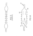
- the tube 12 is a balloon 22, such as is shown in FIG. 6 .
- the balloon 22 may be adapted to provide uniform inflation characteristics by application of one or more deposits of fibrous material 18.
- FIG. 5 labeled PRIOR ART, an example of one type of previously known balloon is shown.
- this type of balloon is inflated such as for example, during a stent delivery procedure, the ends of the balloon tend to inflate first. This non-uniform inflation may provide for uneven delivery of the stent.
- struts or stripes 120 of material 18 are placed near the ends of the balloon 22. The stripes 120 act to transfer inflation stress from the ends of the balloon 22 to the middle portion of the balloon allowing the balloon to inflate more evenly.
- a balloon 22 may be utilized to provide more uniform deployment of a medical device such as stent 20.
- An alternative embodiment of a striped balloon is shown in FIGs. 10 and 11 .
- catheters, balloons and other tubular members may be provided with deposits of material that will affect, enhance or otherwise modify one or more physicaland/or performance characteristics of the tubular member. It should be recognized that in addition to those characteristics described herein, the present invention is also directed to any and all modifications of balloons and catheters utilizing the deposition of a pattern of fibrous material as described in accordance with the present invention herein.
Landscapes
- Health & Medical Sciences (AREA)
- Heart & Thoracic Surgery (AREA)
- Life Sciences & Earth Sciences (AREA)
- Anesthesiology (AREA)
- Hematology (AREA)
- Biophysics (AREA)
- Pulmonology (AREA)
- Engineering & Computer Science (AREA)
- Vascular Medicine (AREA)
- Biomedical Technology (AREA)
- Child & Adolescent Psychology (AREA)
- Animal Behavior & Ethology (AREA)
- General Health & Medical Sciences (AREA)
- Public Health (AREA)
- Veterinary Medicine (AREA)
- Materials For Medical Uses (AREA)
- Media Introduction/Drainage Providing Device (AREA)
- Prostheses (AREA)
- Eyeglasses (AREA)
Abstract
Description
- The use of catheters and medical balloons therewith, for delivery of an expandable, implantable medical device such as a stent, stent-graft, graft or vena cava filter to a desired bodily location are well known in the art. Typically, an expandable, implantable medical device such as a stent is disposed about a balloon which in turn is mounted on a catheter tube. The catheter is inserted into a bodily vessel and advanced to a desired location. The balloon is then inflated so as to expand or assist in expanding the medical device. Where the implantable medical device is self-expandable the catheter may be equipped with a medical device retaining region in addition to or in place of the medical balloon.
- The term 'catheter' as used herein is directed to medical devices such as guide catheters, delivery catheters, balloon catheters, and portions thereof, including but not limited to inflatable members such as balloons.
- In delivering a balloon expandable medical device, it is important that the medical device be accurately positioned on the body or working portion of the balloon. Failure to properly position the medical device on the balloon may result in a non-uniform expansion of the medical device.
- Unfortunately, the proper positioning of such a medical device on a balloon catheter can be a challenging task because the medical device is typically mounted on an uninflated balloon.
- Numerous devices have been employed to help secure an expandable medical device, such as a stent onto a catheter. Such devices include pull-back sheathes which extend over the entire stent to retain the stent to a portion of the catheter. Some examples of sheathes may be found in
US 5772669 ,US 5868755 ,US 4732152 ,US 4848343 ,US 4875480 ,US 5662703 ,US 5690644 ,WO 94/15549 - Some systems have been developed which avoid the need for retractable sheathes by providing a stent delivery catheter with one or more self-retracting sleeves. Some examples of delivery catheters having sleeves which may be self-retractable are described in:
US 4950227 ,US 5403341 ,US 5108416 , and others. - In
US 4950227 to Savin et al., an inflation expandable stent delivery system includes a sleeve which overlaps the distal or proximal margin (or both) of the stent during delivery. During inflation of the stent at the deployment site, the stent margins are freed of the protective sleeve(s).US 5403341 to Solar , relates to a stent delivery and deployment assembly which uses retaining sheaths positioned about opposite ends of the compressed stent. The retaining sheaths of Solar are adapted to tear under pressure as the stent is radially expanded, thus releasing the stent from engagement with the sheaths.US 5108416 to Ryan et al., describes a stent introducer system which uses one or two flexible end caps and an annular socket surrounding the balloon to position the stent during introduction to the deployment site. - Still other systems are known which employ a variety of alternative means for retaining a stent on a catheter prior to deliver. For example, the stent delivery system of
U.S. Pat. App. 09/697608 includes stent securement hubs which engage portions of a stent disposed about a catheter, andEP 696,447 - Still other systems have been developed which employ surface features on the catheter surface to aid in retaining the stent thereabout. Some examples of systems having unique surface features are described in:
WO 00/57816 US 6258099 which describes catheter balloons having engagement protrusions, andUS 6048350 which describes delivery systems employing a combination of securement hubs and balloon segments to aid in retaining a stent there on. - An advantage of providing a stent delivery catheter and/or balloon with surface features that promote stent retention prior to delivery is that the profile of the catheter may be minimized as there may be no need to include additional sheathes, sleeves or other members which would otherwise overlap the stent and increase the profile of the catheter. Another advantage of providing a catheter with stent retaining surface features is that by removing the need for retractable members, the need for relatively bulky or complex retraction systems is likewise removed, thereby providing a delivery system which may be much more simple and safer to use.
- Expandable medical devices such as stents have a wide variety of shapes, sizes and configurations. For example, it is known that a stent having a particular strut pattern may have performance characteristics which are significantly different than a stent having a different strut pattern. As a result, it would be desirable to provide individual catheters with varying types of surface feature patterns in order to maximize the effectiveness of the surface pattern in retaining a stent of a particular configuration. Unfortunately, typical manufacturing processes of catheters do not readily lend themselves to individualized production of different catheter types.
- Typically, catheters are formed of extruded material which is then shaped or molded into the final catheter shape. Providing dozens of different molds for a wide range of surface feature patterns may be cost prohibitive as well as extremely inefficient from a manufacturing perspective. Thus, it would be desirable to provide a method for applying a unique surface feature pattern to catheters which may be cheaply and easily employed on an individual basis.
- From
WO 02/07795 A2 - Without limiting the scope of the invention a brief summary of some of the claimed embodiments of the invention is set forth below. Additional details of the summarized embodiments of the inventionand/or additional embodiments of the invention may be found in the Detailed Description of the Invention below.
- The present invention includes many different embodiments. Some of the embodiments are directed to catheters in general and in some embodiments to catheter balloons for angioplasty or advantageously for use in the delivery of medical devices such as stents.
- Some embodiments of the invention are directed to catheters having a textured, partially textured or otherwise marked surface which provides the catheter with improved stent retaining characteristics. The texturing or marking facilitates the positioning of an expandable, implantable medical device on the catheter and increases the securement of a stent or other expandable, implantable medical device to the catheter.
- In at least one embodiment of the invention, a catheter, balloon or other tubular shaft may be provided with a deposited pattern of material. The deposited material may be characterized as any material that may be used to modify the physical properties of the tubing, such as for example flexibility, via the configuration, location, and/or other characteristic of the pattern and the physical properties of the deposited material.
- In at least one embodiment, the material deposited on the catheter or balloon shaft is a fibrous material. The material may be, but is not limited to inorganic ceramics.
- In at least one embodiment, the deposited material is provided with a pattern which is constructed and arranged to improve retention and engagement between the catheter and/or balloon surface and a stent or other implantable medical device that may be disposed thereabout.
- In at least some embodiments, the deposited pattern of material is of a material having a different composition than that of the underlying catheter or balloon tubing.
- In at least one embodiment of the invention, material deposited on a balloon or catheter is a continuous film. Alternatively the deposited material may be a discontinuous coating or deposit. The deposited material may be deposited on the tubing in a pattern comprised of features such as helical, longitudinal, crossed, and/or radial stripes, or any pattern desired. In some embodiments of the invention, the deposited material is oriented on the tubing in one or more longitudinally tapering stripes.
- In some embodiments where the invention is directed to a balloon, the surface of the balloon is provided with one or more deposited struts of material which act to provide the balloon with uniform inflation characteristics. During balloon inflation, the strut or struts can act to transfer stress from the ends of the balloon to the middle portion of the balloon.
- In some embodiments of the invention, material deposited on a catheter or balloon, is deposited by one or more techniques including: solution coating, spray coating, thermal printing, piezo jet printing, contact printing, etc.
- In at least one embodiment of the invention, the particular method utilized to deposit the material on the catheter/balloon tube may include one or more of the following steps: a curing step or steps, initial surface treatment step or steps, a post-deposition processing step or steps, etc.
- In the various embodiments of the invention, the resulting selectively coated catheter and/or balloon tubular member will be provided with one or more physical characteristics that are different than the tubular member would have had without the deposition of material. Through the application of a deposited material to a tubular member, for use as a catheter, balloon or other medical device, the tubular member may be provided with a variety of desired performance characteristics. Some examples of characteristics that may be altered or improved according to the present invention include but are not limited to: flexular modulus, elasticity, columnar strength, kink resistance, burst pressure, compliance, among others.
- Additional details and/or embodiments of the invention are discussed below.
- A detailed description of the invention is hereafter described with specific reference being made to the drawings.
-
FIG. 1 is a side elevational view of an embodiment of the invention wherein a portion of a catheter is shown with one a pattern of material placed thereon. -
FIG. 2 is a side elevational view of an embodiment of the invention wherein a portion of a catheter is shown with one a pattern of material placed thereon. -
FIG. 3 is a side elevational view of an embodiment of the invention illustrating the engagement of a medical device to a catheter having a pattern of material which corresponds to openings in the framework of the medical device. -
FIG. 4 is a cross-sectional view of an embodiment of the invention. -
FIG. 5 , labeled PRIOR ART, shows a side view of one type of known balloon during inflation. -
FIG. 6 is a side view of an embodiment of the invention directed to a balloon shown during inflation. -
FIG. 7 is a side view of an embodiment of the invention showing a pattern of material placed on a section of catheter tubing. -
FIG. 8 is a side view of an embodiment of the invention showing a pattern of material placed on a section of catheter tubing. -
FIG. 9 is a side view of an embodiment of the invention showing a pattern of material placed on a section of catheter tubing. -
FIG. 10 is a side view of an embodiment of the invention showing a pattern of material placed on a section of catheter tubing. -
FIG. 11 is a side view of an embodiment of the invention showing a pattern of material placed on a section of catheter tubing. - The present invention includes many different embodiments. For example, in
FIGs. 1 and 2 embodiments of the invention are shown wherein different forms of medical device, such as acatheter 10 are respectively depicted.Catheter 10 may be any type of elongate medical device or portion thereof, such as a balloon, capable of being inserted into a body lumen and advanced therethrough. Numerous types and configurations of such medical devices are known and the term "catheter" as used herein is merely a convenient term used to designate all such devices. - In the various embodiments described herein,
catheter 10 may be manufactured from a catheter material ortube 12. Thecatheter 10 includes adistal region 14 which has anouter surface 16 having a pattern of indented or raisedmaterial 18 thereon. - In some embodiments, a deposited
material 18 can be characterized as being soft or tacky when compared to the surroundingmaterial 12. However,material 18 that is comparatively hard, relative to thecatheter material 12 may also be used. In some embodiments of the invention, thematerials -
FIGs. 1 and 2 illustrate merely two potential patterns ofmaterial 18 which acatheter 10 may be configured with. As is shown inFIG. 3 , such unique patterns are useful in securing an expandable medical device, such as for example astent 20 to thecatheter surface 16 prior to delivery of thestent 20. - As is known, medical devices such as stents may be self-expandable, balloon expandable or maybe a hybrid of the two more common types. Stents of all types may be included with appropriate embodiments of the present invention. For example, in order to deliver and expand a balloon expandable stent, the
distal region 14 of thecatheter 10 may be equipped with an expandable member orballoon 22. Wherestent 20 is a self-expanding stent or a hybrid device,balloon 22 may be used to trigger or aid in stent delivery and may further be used to seat the stent into place within the body lumen. - In the embodiments shown in
FIGs. 1 and 2 thedistal region 14 may include aballoon 22 therewith. Where any embodiment of the present invention includes aballoon 22, it is understood that thecatheter 10 will further include an inflation means such as an inflation lumen or similar device (not shown) to inflate theballoon 22 for stent delivery or other purposes as is known in the art. - In various embodiments of the invention, the
material 18 may be characterized as any substance or substances that alter the physical properties of thecatheter 10, such as the ability of thecatheter surface 16 to interact with a medical device such asstent 20 disposed thereabout. For example, where thematerial 18 is a higher modulus material than thecatheter material 12, thematerial 18 may provide thecatheter 10 with improved ability to removably engage thestent 20 mounted thereon such as is shown inFIGs. 3 and6 . A wide variety of substances may comprisematerial 18.Material 18 may include, but is not limited to: inorganic ceramic substances. - In some examples, the
material 18 is a fibrous material comprising organic and/or inorganic thermoset compositions. Some organic thermoset compositions may comprise for example: linear or branched resin systems containing epoxy, urethane, imide, ester, ketene, sulphone or urea functionalities. Organic thermosets may also contain vinyl or allylic functionalities, such as vinyl esters and cyanoacrylates, for example. Phenolic and silicone containing resins would also be included. Inorganic fibrous materials may contain thermoset compositions comprising alkoxides of silicon, aluminum, titanium, zirconcium, etc. In some embodiments carbon fiber may also be used. - In addition to organic thermoset polymers, inorganic thermoset polymers and blends thereof, some examples of the invention may include a material 18 that is a thermoset composition comprising mesogenic functionalities which provide liquid crystalline properties to the thermoset. For example, in at least one example,
material 18 includes resin compositions having planar aromatic functionalities such as: 4-4'-di(2,3 epoxypropyloxy) phenyl benzoate, diamino diphenyl ester, 2,6 napthalene - di[4-(2-propenyloxy) benzoate], diamino diphenly sulfone, methylene dianiline, dicyatonapthalene, resorcinol diglycidyl ether, diaminonapthalene, napthalene diol, and p-phenylene diamine among others. - In some embodiments
fibrous material 18 may contain additional fillers to enhance the properties of the thermoset. These fillers may be conventional fillers such as glass fiber, carbon, etc. In some embodiments the material may contain nanocomposite fillers such as intercalated and /or exfoliated clays such as, for example: montmorillonite, hectorites, hydrotalcites, vermiculite, and laponite. Other filler materials include, for example, monomeric silicates such as polyhedral oligomer silesequioxanes (POSS), carbon and ceramic nanotubes and fibers, nano-wires, and nano-fibers including single and multiwalled fullerenes, silica nano-gels, alumina nano-fibers, metal and metal oxide powders including alumina oxide, titanium oxide, gold, silver, platinum, and magnetic powders such as neodenium iron boron. - In some embodiments the
material 18, or one or more components thereof, may be at characterized as being at least partially radio or MRI opaque. - Where
material 18 is a thermoset, thematerial 18 may be deposited in multiple parts to enable a curing step. There may be additional processing steps including predeposition treatment of thesurface 16 and post-deposition processing. Post-deposition processing may include a curing step that requires exposure of the material to an energy source such as IR or UV energy. As a result, depending on the particular substance selected to act asmaterial 18 and the particular pattern employed the physical properties of thecatheter 10 may be altered as desired. - Placement of the material 18 on the
catheter surface 16 may be accomplished by a variety of deposition or coating methods. Such methods include but are not limited to the use of: solution coating, spray coating, thermal printing, piezo jet printing, contact printing, among others. - As is illustrated in
FIGs. 1-3 , thematerial 18 may be placed on thecatheter 10 in any pattern desired. Some additional patterns ofmaterial 18 deposition are shown inFIGs. 7-11 . InFIG. 7 for example thematerial 18 comprises a plurality ofstripes 120 which increase in thickness as thestripes 120 extend longitudinally along the length of thecatheter 10. In some embodiments, thestripes 120 continue to increase until they contact one another to form acontinuous band 122 about a portion of thecatheter material 12. - In
FIG. 8 thematerial 18 is applied as at least one helically orientedstrip 120. - In
FIG. 9 thematerial 18 is deposited in a pattern of substantially parallel longitudinally orientedstripes 120. - In the embodiment shown in
FIGs. 10 and 11 , thematerial 18 is shown deposited only on theballoon portion 22 of acatheter 10. While thematerial 18 is shown limited only to the body portion of the balloon, in some embodiments, thematerial 18 may be selectively applied to thecatheter 10 to be included on one or more cones and/or the body portion of theballoon 22. - The unique patterns of deposited
material 18 used in the various embodiments described herein may provide a tubular member such as a catheter or balloon with stiffer or softer segments. In all of the various embodiments shown, thematerial 18 may be deposited on theexternal catheter surface 16 or the internal catheter surface as desired. - In the embodiments shown in
FIGs. 1 and 2 the unique patterns of depositedmaterial 18 may be raised to extend outward relative to thecatheter surface 16. InFIG. 4 , the profile of thecatheter 10 may be seen wherein thematerial 18 extends outward from thesurface 16 of theballoon 22. - Regardless of the particular pattern of
material 18 applied to thesurface 16, the pattern ofmaterial 18 can provide thecatheter 10 with a textured surface capable of engaging astent 20 or other medical device such as is shown inFIG. 3 . - Stents typically comprise a
framework 30 of interconnected struts andmembers 32 which define a plurality ofopenings 34 therebetween. Stents have a variety of strut patterns as well as a variety of opening sizes and shapes.Catheter 10 may be equipped with a pattern of depositedmaterial 18 which acts to at least partially pass through the various openings of the stent in the reduced configuration. The unique pattern ofmaterial 18 may engage thestent 20 to retain the stent in the reduced predelivery state without the need for one or more retaining sheathes or members. Preferably, theindividual protrusions 36 of the pattern ofmaterial 18 pass at least partially through correspondingly positionedopenings 34 of thestent framework 30 to retain thestent 20 to thedistal region 14 of thecatheter 10 prior to delivery of thestent 20. Theprotrusions 36 engage thestent 20 by extending into theopenings 34 to about 30 percent to about 100 percent of the thickness of thestent 20. - In addition to providing a catheter with improved medical device retaining characteristics, a tubular member that is provided with a coating or pattern of deposits of material may be provided with a variety of enhanced or modified characteristics. For example, by providing a pattern of material that is harder than the material of the tube, a catheter or other device made therefrom may be imparted with improved kink resistance due to the presence of the harder deposited material.
- In at least one embodiment of the invention, the
tube 12 is aballoon 22, such as is shown inFIG. 6 . In such an embodiment theballoon 22 may be adapted to provide uniform inflation characteristics by application of one or more deposits offibrous material 18. - In
FIG. 5 , labeled PRIOR ART, an example of one type of previously known balloon is shown. As may be seen inFIG. 5 when this type of balloon is inflated such as for example, during a stent delivery procedure, the ends of the balloon tend to inflate first. This non-uniform inflation may provide for uneven delivery of the stent. In the embodiment of the invention shown inFIG. 6 however, struts orstripes 120 ofmaterial 18 are placed near the ends of theballoon 22. Thestripes 120 act to transfer inflation stress from the ends of theballoon 22 to the middle portion of the balloon allowing the balloon to inflate more evenly. As a result, aballoon 22 may be utilized to provide more uniform deployment of a medical device such asstent 20. An alternative embodiment of a striped balloon is shown inFIGs. 10 and 11 . - In addition to the embodiments described herein, in accordance with the above disclosure it is evident that catheters, balloons and other tubular members may be provided with deposits of material that will affect, enhance or otherwise modify one or more physicaland/or performance characteristics of the tubular member. It should be recognized that in addition to those characteristics described herein, the present invention is also directed to any and all modifications of balloons and catheters utilizing the deposition of a pattern of fibrous material as described in accordance with the present invention herein.
Claims (12)
- A substantially tubular member comprising:a body (22), the body (22) constructed from a first material (12), the body (22) having an external surface (16), at least a portion of the external surface (16) having a predetermined pattern of a second material (18) deposited thereon, the second material (18) comprising a fibrous material, characterized in that the predetermined pattern of the second material is deposited on the at least a portion of the external surface by at least one printing process selected from the group consisting of: solution coating, spray coating, thermal printing, piezo jet printing, contact printing and any combination thereof, and in that the fibrous material is selected from the group consisting of: inorganic ceramics and thermosets with a filler.
- The substantially tubular member of claim 1 wherein the predetermined pattern of a second material defines at least one raised portion (36) of the at least a portion of the external surface (16) of the body.
- The substantially tubular member of claim 1 or 2 wherein the predetermined pattern of a second material defines at least one substantially longitudinally oriented stripe (120) on the at least a portion of the external surface (16) of the body (22).
- The substantially tubular member of claim 3 wherein the at least one substantially longitudinally oriented stripe (120) comprises a plurality of stripes.
- The substantially tubular member of any of the claims 1 to 4 wherein the predetermined pattern of a second material is an irregular pattern.
- The substantially tubular member of any of the claims 1 to 4 wherein the predetermined pattern of a second material is a regular pattern.
- The substantially tubular member of any of claims 1 to 6 wherein the body comprises a catheter (10).
- The substantially tubular member of claim 7 wherein the external surface (16) comprises a medical device receiving region, the predetermined pattern of a second material constructed and arranged to retain a medical device (20) to the medical device receiving region prior to delivery of the medical device (20).
- The substantially tubular member of claim 8 wherein the medical device receiving region is an expandable balloon (22).
- The substantially tubular member of claim 9 wherein the medical device is a stent (20) removably engaged to the at least a portion of the medical device receiving region, the predetermined pattern of a second material (18) substantially engaging the stent (20) prior to delivery.
- The substantially tubular member of any of the claims 1 to 10 wherein the predetermined pattern of a second material (18) is a material that is softer than the first material (12).
- The substantially tubular member of any of the claims 1 to 10 wherein the predetermined pattern of a second material (18) is a material that is harder than the first material (12).
Applications Claiming Priority (3)
| Application Number | Priority Date | Filing Date | Title |
|---|---|---|---|
| US330506 | 1994-10-28 | ||
| US10/330,506 US6841213B2 (en) | 2002-12-27 | 2002-12-27 | Fiber pattern printing |
| PCT/US2003/036980 WO2004060472A1 (en) | 2002-12-27 | 2003-11-19 | Catheter balloon having a suface pattern and method of manufacture |
Publications (2)
| Publication Number | Publication Date |
|---|---|
| EP1575655A1 EP1575655A1 (en) | 2005-09-21 |
| EP1575655B1 true EP1575655B1 (en) | 2008-10-01 |
Family
ID=32654509
Family Applications (1)
| Application Number | Title | Priority Date | Filing Date |
|---|---|---|---|
| EP03783685A Expired - Lifetime EP1575655B1 (en) | 2002-12-27 | 2003-11-19 | Catheter balloon having a surface pattern and method of manufacture |
Country Status (9)
| Country | Link |
|---|---|
| US (2) | US6841213B2 (en) |
| EP (1) | EP1575655B1 (en) |
| JP (1) | JP2006512145A (en) |
| AT (1) | ATE409507T1 (en) |
| AU (1) | AU2003291096A1 (en) |
| CA (1) | CA2509875A1 (en) |
| DE (1) | DE60323873D1 (en) |
| ES (1) | ES2315552T3 (en) |
| WO (1) | WO2004060472A1 (en) |
Families Citing this family (56)
| Publication number | Priority date | Publication date | Assignee | Title |
|---|---|---|---|---|
| US7776078B2 (en) * | 2003-05-22 | 2010-08-17 | Boston Scientfic Scimed, Inc. | Catheter balloon with improved retention |
| US7758572B2 (en) | 2004-05-20 | 2010-07-20 | Boston Scientific Scimed, Inc. | Medical devices and methods including cooling balloons having nanotubes |
| US8092910B2 (en) * | 2005-02-16 | 2012-01-10 | Dow Corning Toray Co., Ltd. | Reinforced silicone resin film and method of preparing same |
| WO2006088645A1 (en) * | 2005-02-16 | 2006-08-24 | Dow Corning Corporation | Reinforced silicone resin film and method of preparing same |
| US8672990B2 (en) * | 2005-05-27 | 2014-03-18 | Boston Scientific Scimed, Inc. | Fiber mesh controlled expansion balloon catheter |
| JP2009503230A (en) * | 2005-08-04 | 2009-01-29 | ダウ・コーニング・コーポレイション | Reinforced silicone resin film and method for producing the same |
| US7867169B2 (en) * | 2005-12-02 | 2011-01-11 | Abbott Cardiovascular Systems Inc. | Echogenic needle catheter configured to produce an improved ultrasound image |
| ATE517947T1 (en) | 2005-12-21 | 2011-08-15 | Dow Corning | SILICONE RESIN FILM, PRODUCTION METHOD THEREOF AND NANOMATERIAL-FILLED SILICONE COMPOSITION |
| US8264137B2 (en) * | 2006-01-03 | 2012-09-11 | Samsung Electronics Co., Ltd. | Curing binder material for carbon nanotube electron emission cathodes |
| JP5543111B2 (en) * | 2006-01-19 | 2014-07-09 | ダウ・コーニング・コーポレイション | Self-supporting silicone resin film, preparation method thereof, and nanomaterial-filled silicone composition for self-supporting silicone resin film |
| WO2007092118A2 (en) * | 2006-02-02 | 2007-08-16 | Dow Corning Corporation | Silicone resin film, method of preparing same, and nanomaterial-filled silicone composition |
| WO2007097835A2 (en) * | 2006-02-20 | 2007-08-30 | Dow Corning Corporation | Silicone resin film, method of preparing same, and nanomaterial-filled silicone composition |
| US7794402B2 (en) * | 2006-05-15 | 2010-09-14 | Advanced Cardiovascular Systems, Inc. | Echogenic needle catheter configured to produce an improved ultrasound image |
| KR20090074758A (en) * | 2006-10-05 | 2009-07-07 | 다우 코닝 코포레이션 | Silicone resin film and method of preparing same |
| US7857786B2 (en) * | 2006-11-03 | 2010-12-28 | Cook Incorporated | Balloon catheter having improved balloon folding capability |
| KR20090107529A (en) * | 2007-02-06 | 2009-10-13 | 다우 코닝 코포레이션 | Silicone resin, silicone composition, coated substrate, and reinforced silicone resin film |
| WO2008103229A1 (en) * | 2007-02-22 | 2008-08-28 | Dow Corning Corporation | Reinforced silicone resin film and method of preparing same |
| WO2008103226A1 (en) * | 2007-02-22 | 2008-08-28 | Dow Corning Corporation | Reinforced silicone resin films |
| EP2117836B1 (en) * | 2007-02-22 | 2012-11-07 | Dow Corning Corporation | Reinforced silicone resin films |
| US8628746B2 (en) * | 2007-04-12 | 2014-01-14 | Raytheon Company | System and method for dispersing nanostructures in a composite material |
| WO2008134241A1 (en) * | 2007-05-01 | 2008-11-06 | Dow Corining Corporation | Nanomaterial-filled silicone composition and reinforced silicone resin film |
| EP2142589A2 (en) * | 2007-05-01 | 2010-01-13 | Dow Corning Corporation | Reinforced silicone resin film |
| US8491292B1 (en) | 2007-07-31 | 2013-07-23 | Raytheon Company | Aligning nanomaterial in a nanomaterial composite |
| US8636972B1 (en) | 2007-07-31 | 2014-01-28 | Raytheon Company | Making a nanomaterial composite |
| US20090082847A1 (en) * | 2007-09-26 | 2009-03-26 | Boston Scientific Corporation | System and method of securing stent barbs |
| US20090082845A1 (en) * | 2007-09-26 | 2009-03-26 | Boston Scientific Corporation | Alignment stent apparatus and method |
| US8226701B2 (en) | 2007-09-26 | 2012-07-24 | Trivascular, Inc. | Stent and delivery system for deployment thereof |
| US8066755B2 (en) * | 2007-09-26 | 2011-11-29 | Trivascular, Inc. | System and method of pivoted stent deployment |
| US20090082841A1 (en) * | 2007-09-26 | 2009-03-26 | Boston Scientific Corporation | Apparatus for securing stent barbs |
| US8663309B2 (en) * | 2007-09-26 | 2014-03-04 | Trivascular, Inc. | Asymmetric stent apparatus and method |
| EP2194921B1 (en) * | 2007-10-04 | 2018-08-29 | TriVascular, Inc. | Modular vascular graft for low profile percutaneous delivery |
| JP5485896B2 (en) * | 2007-10-12 | 2014-05-07 | ダウ コーニング コーポレーション | Aluminum oxide dispersion and method for preparing the same |
| WO2009048694A1 (en) * | 2007-10-12 | 2009-04-16 | Dow Corning Corporation | Reinforced silicone resin film and nanofiber-filled silicone composition |
| US8083789B2 (en) * | 2007-11-16 | 2011-12-27 | Trivascular, Inc. | Securement assembly and method for expandable endovascular device |
| US8328861B2 (en) * | 2007-11-16 | 2012-12-11 | Trivascular, Inc. | Delivery system and method for bifurcated graft |
| US20100331958A1 (en) * | 2007-12-20 | 2010-12-30 | Trivascular, Inc. | Hinged endovascular device |
| US8187221B2 (en) | 2008-07-11 | 2012-05-29 | Nexeon Medsystems, Inc. | Nanotube-reinforced balloons for delivering therapeutic agents within or beyond the wall of blood vessels, and methods of making and using same |
| US20100145429A1 (en) * | 2008-12-09 | 2010-06-10 | Cook Incorporated | Introducer sheath and method of manufacture |
| US20110218609A1 (en) * | 2010-02-10 | 2011-09-08 | Trivascular, Inc. | Fill tube manifold and delivery methods for endovascular graft |
| US9227041B2 (en) | 2010-04-09 | 2016-01-05 | Boston Scientific Scimed, Inc. | Balloon catheters with fibers for delivery of therapeutic agent and methods of making the same |
| US8795312B2 (en) * | 2010-11-12 | 2014-08-05 | Smith & Nephew, Inc. | Inflatable, steerable balloon for elevation of tissue within a body |
| US9730726B2 (en) | 2011-10-07 | 2017-08-15 | W. L. Gore & Associates, Inc. | Balloon assemblies having controllably variable topographies |
| US8992595B2 (en) | 2012-04-04 | 2015-03-31 | Trivascular, Inc. | Durable stent graft with tapered struts and stable delivery methods and devices |
| US9498363B2 (en) | 2012-04-06 | 2016-11-22 | Trivascular, Inc. | Delivery catheter for endovascular device |
| US20140135907A1 (en) * | 2012-11-09 | 2014-05-15 | Medtronic CV Luxembourg S.a.r.l. | Medical Device Delivery System and Methods of Delivering Medical Devices |
| US20140277071A1 (en) * | 2013-03-12 | 2014-09-18 | Acclarent, Inc. | Features to enhance grip of balloon within airway |
| US9669194B2 (en) | 2013-03-14 | 2017-06-06 | W. L. Gore & Associates, Inc. | Conformable balloon devices and methods |
| CN106029116A (en) | 2014-01-02 | 2016-10-12 | 波士顿科学国际有限公司 | Drug eluting balloon with preferred drug orientation to improve drug transfer efficiency |
| GB2529720A (en) * | 2014-09-01 | 2016-03-02 | Cook Medical Technologies Llc | Shaped or textured medical balloon with strengthening elements |
| CN112426253A (en) | 2015-05-27 | 2021-03-02 | 特里瓦斯库拉尔公司 | Balloon assisted endoluminal prosthesis deployment |
| WO2017096350A1 (en) | 2015-12-05 | 2017-06-08 | The Regents Of The University Of Colorado, A Body Corporate | Novel endoscopic devices and methods using same |
| US11089944B2 (en) | 2018-01-16 | 2021-08-17 | The Regents Of The University Of Colorado | Medical devices including textured inflatable balloons |
| US11577056B2 (en) | 2018-01-16 | 2023-02-14 | Aspero Medical, Inc. | Medical devices including textured inflatable balloons |
| US11730928B2 (en) | 2018-01-16 | 2023-08-22 | Aspero Medical, Inc. | Split overtube assembly |
| CA3108318A1 (en) * | 2018-08-24 | 2020-02-27 | C.R. Bard, Inc. | Inflatable medical balloon with s-shaped fiber |
| EP3908180A2 (en) * | 2019-01-09 | 2021-11-17 | King Abdullah University Of Science And Technology | Panel and method for manufacturing the panel |
Family Cites Families (40)
| Publication number | Priority date | Publication date | Assignee | Title |
|---|---|---|---|---|
| ES8705239A1 (en) | 1984-12-05 | 1987-05-01 | Medinvent Sa | A device for implantation and a method of implantation in a vessel using such device. |
| SE454482B (en) | 1986-09-30 | 1988-05-09 | Medinvent Sa | DEVICE FOR IMPLANTATION |
| SE455834B (en) | 1986-10-31 | 1988-08-15 | Medinvent Sa | DEVICE FOR TRANSLUMINAL IMPLANTATION OF A PRINCIPLE RODFORMALLY RADIALLY EXPANDABLE PROSTHESIS |
| US4793348A (en) | 1986-11-15 | 1988-12-27 | Palmaz Julio C | Balloon expandable vena cava filter to prevent migration of lower extremity venous clots into the pulmonary circulation |
| US4950227A (en) | 1988-11-07 | 1990-08-21 | Boston Scientific Corporation | Stent delivery system |
| US5108416A (en) | 1990-02-13 | 1992-04-28 | C. R. Bard, Inc. | Stent introducer system |
| JPH0564660A (en) * | 1991-05-21 | 1993-03-19 | Sumitomo Bakelite Co Ltd | Medical catheter and making thereof |
| WO1994015549A1 (en) | 1992-12-30 | 1994-07-21 | Schneider (Usa) Inc. | Apparatus for deploying body implantable stents |
| US5746745A (en) | 1993-08-23 | 1998-05-05 | Boston Scientific Corporation | Balloon catheter |
| JPH09507148A (en) * | 1994-01-06 | 1997-07-22 | シメッド ライフ システムズ インコーポレイテッド | Thermoplastic polyimide balloon catheter |
| US5403341A (en) | 1994-01-24 | 1995-04-04 | Solar; Ronald J. | Parallel flow endovascular stent and deployment apparatus therefore |
| US5683451A (en) | 1994-06-08 | 1997-11-04 | Cardiovascular Concepts, Inc. | Apparatus and methods for deployment release of intraluminal prostheses |
| US6306144B1 (en) | 1996-11-01 | 2001-10-23 | Scimed Life Systems, Inc. | Selective coating of a balloon catheter with lubricious material for stent deployment |
| NL1000106C2 (en) * | 1995-04-10 | 1996-10-11 | Cordis Europ | Balloon balloon balloon catheter and method of making the balloon. |
| DE69626108T2 (en) | 1995-04-14 | 2003-11-20 | Boston Scient Ltd | STENTING DEVICE WITH ROLLING MEMBRANE |
| US5772669A (en) | 1996-09-27 | 1998-06-30 | Scimed Life Systems, Inc. | Stent deployment catheter with retractable sheath |
| US6146814A (en) * | 1996-12-27 | 2000-11-14 | Millet; Marcus J. | Methods of making composite catheters |
| US5868755A (en) | 1997-01-16 | 1999-02-09 | Atrion Medical Products, Inc. | Sheath retractor mechanism and method |
| US5888577A (en) * | 1997-06-30 | 1999-03-30 | Procath Corporation | Method for forming an electrophysiology catheter |
| US6242063B1 (en) * | 1997-09-10 | 2001-06-05 | Scimed Life Systems, Inc. | Balloons made from liquid crystal polymer blends |
| US6129706A (en) * | 1998-12-10 | 2000-10-10 | Janacek; Jaroslav | Corrugated catheter balloon |
| US5976155A (en) * | 1999-03-05 | 1999-11-02 | Advanced Cardiovascular Systems, Inc. | System for removably securing a stent on a catheter assembly and method of use |
| US6183505B1 (en) | 1999-03-11 | 2001-02-06 | Medtronic Ave, Inc. | Method of stent retention to a delivery catheter balloon-braided retainers |
| US6786889B1 (en) | 1999-03-31 | 2004-09-07 | Scimed Life Systems, Inc | Textured and/or marked balloon for stent delivery |
| US6258099B1 (en) | 1999-03-31 | 2001-07-10 | Scimed Life Systems, Inc. | Stent security balloon/balloon catheter |
| US6048350A (en) | 1999-06-14 | 2000-04-11 | Scimed Life Systems, Inc. | Segmented balloon delivery system |
| US6325780B1 (en) * | 1999-09-13 | 2001-12-04 | Advanced Cardiovascular Systems, Inc. | Inflatable member formed of liquid crystal polymeric material blend |
| DE19952505A1 (en) * | 1999-10-29 | 2001-05-03 | Gerd Hausdorf | An expandable balloon for medical use comprises a thin-walled polymer shell coated with radio-opaque material in a pattern and is expandable on introduction of liquid and increasing pressure |
| US7479128B1 (en) * | 2000-01-04 | 2009-01-20 | Boston Scientific Scimed, Inc. | Protective coatings for medical devices |
| US6447835B1 (en) | 2000-02-15 | 2002-09-10 | Scimed Life Systems, Inc. | Method of coating polymeric tubes used in medical devices |
| US6440503B1 (en) * | 2000-02-25 | 2002-08-27 | Scimed Life Systems, Inc. | Laser deposition of elements onto medical devices |
| US6494894B2 (en) | 2000-03-16 | 2002-12-17 | Scimed Life Systems, Inc. | Coated wire |
| US6395326B1 (en) * | 2000-05-31 | 2002-05-28 | Advanced Cardiovascular Systems, Inc. | Apparatus and method for depositing a coating onto a surface of a prosthesis |
| AU2001282959A1 (en) * | 2000-07-24 | 2002-02-05 | Jeffrey Grayzel | Stiffened balloon catheter for dilatation and stenting |
| US6656211B1 (en) * | 2000-10-26 | 2003-12-02 | Scimed Life Systems, Inc. | Stent delivery system with improved tracking |
| US6682771B2 (en) * | 2001-07-02 | 2004-01-27 | Scimed Life Systems, Inc. | Coating dispensing system and method using a solenoid head for coating medical devices |
| US7985234B2 (en) * | 2002-02-27 | 2011-07-26 | Boston Scientific Scimed, Inc. | Medical device |
| US6989025B2 (en) * | 2002-10-04 | 2006-01-24 | Boston Scientific Scimed, Inc. | Extruded tubing with discontinuous striping |
| US7776078B2 (en) * | 2003-05-22 | 2010-08-17 | Boston Scientfic Scimed, Inc. | Catheter balloon with improved retention |
| US20040247775A1 (en) * | 2003-06-06 | 2004-12-09 | Boulais Dennis R. | Positive displacement coating deposition apparatus and method |
-
2002
- 2002-12-27 US US10/330,506 patent/US6841213B2/en not_active Expired - Lifetime
-
2003
- 2003-11-19 WO PCT/US2003/036980 patent/WO2004060472A1/en active Application Filing
- 2003-11-19 JP JP2004565029A patent/JP2006512145A/en active Pending
- 2003-11-19 AU AU2003291096A patent/AU2003291096A1/en not_active Abandoned
- 2003-11-19 DE DE60323873T patent/DE60323873D1/en not_active Expired - Lifetime
- 2003-11-19 ES ES03783685T patent/ES2315552T3/en not_active Expired - Lifetime
- 2003-11-19 EP EP03783685A patent/EP1575655B1/en not_active Expired - Lifetime
- 2003-11-19 AT AT03783685T patent/ATE409507T1/en not_active IP Right Cessation
- 2003-11-19 CA CA002509875A patent/CA2509875A1/en not_active Abandoned
-
2004
- 2004-12-28 US US11/027,813 patent/US7459192B2/en not_active Expired - Fee Related
Also Published As
| Publication number | Publication date |
|---|---|
| US6841213B2 (en) | 2005-01-11 |
| EP1575655A1 (en) | 2005-09-21 |
| CA2509875A1 (en) | 2004-07-22 |
| DE60323873D1 (en) | 2008-11-13 |
| JP2006512145A (en) | 2006-04-13 |
| WO2004060472A1 (en) | 2004-07-22 |
| AU2003291096A1 (en) | 2004-07-29 |
| US20040126526A1 (en) | 2004-07-01 |
| ES2315552T3 (en) | 2009-04-01 |
| ATE409507T1 (en) | 2008-10-15 |
| US7459192B2 (en) | 2008-12-02 |
| US20050113749A1 (en) | 2005-05-26 |
Similar Documents
| Publication | Publication Date | Title |
|---|---|---|
| EP1575655B1 (en) | Catheter balloon having a surface pattern and method of manufacture | |
| EP2242528B1 (en) | Method for manufacturing the balloon for the treatment of stenosis | |
| JP4309286B2 (en) | Balloon catheter and method for providing a longitudinal axial channel in a lesion | |
| EP1935376B1 (en) | Stent with cutting element | |
| US20020120321A1 (en) | Stent retention mechanism | |
| EP4052680A1 (en) | Anti-migration micropatterned stent coating | |
| US20060184112A1 (en) | Medical devices | |
| US20110301565A1 (en) | Medical balloons having a sheath designed to facilitate release of therapeutic agent | |
| JP2002539888A (en) | Stent security balloon catheter | |
| EP1848487A1 (en) | Medical devices | |
| EP1624920B1 (en) | Balloon with improved retention | |
| CN113057717B (en) | Balloon catheter | |
| EP4045128B1 (en) | Cutting balloon catheter | |
| US20080009799A1 (en) | Resilient protection sleeve for balloon catheter | |
| CN115515656A (en) | Medical device delivery system with improved medical device retention |
Legal Events
| Date | Code | Title | Description |
|---|---|---|---|
| PUAI | Public reference made under article 153(3) epc to a published international application that has entered the european phase |
Free format text: ORIGINAL CODE: 0009012 |
|
| 17P | Request for examination filed |
Effective date: 20050702 |
|
| AK | Designated contracting states |
Kind code of ref document: A1 Designated state(s): AT BE BG CH CY CZ DE DK EE ES FI FR GB GR HU IE IT LI LU MC NL PT RO SE SI SK TR |
|
| AX | Request for extension of the european patent |
Extension state: AL LT LV MK |
|
| DAX | Request for extension of the european patent (deleted) | ||
| RIN1 | Information on inventor provided before grant (corrected) |
Inventor name: MILLER, PAUL, J. Inventor name: PARSONAGE, EDWARD |
|
| 17Q | First examination report despatched |
Effective date: 20060127 |
|
| GRAP | Despatch of communication of intention to grant a patent |
Free format text: ORIGINAL CODE: EPIDOSNIGR1 |
|
| GRAS | Grant fee paid |
Free format text: ORIGINAL CODE: EPIDOSNIGR3 |
|
| GRAA | (expected) grant |
Free format text: ORIGINAL CODE: 0009210 |
|
| AK | Designated contracting states |
Kind code of ref document: B1 Designated state(s): AT BE BG CH CY CZ DE DK EE ES FI FR GB GR HU IE IT LI LU MC NL PT RO SE SI SK TR |
|
| REG | Reference to a national code |
Ref country code: GB Ref legal event code: FG4D |
|
| REG | Reference to a national code |
Ref country code: CH Ref legal event code: EP |
|
| REG | Reference to a national code |
Ref country code: IE Ref legal event code: FG4D |
|
| REF | Corresponds to: |
Ref document number: 60323873 Country of ref document: DE Date of ref document: 20081113 Kind code of ref document: P |
|
| PG25 | Lapsed in a contracting state [announced via postgrant information from national office to epo] |
Ref country code: SI Free format text: LAPSE BECAUSE OF FAILURE TO SUBMIT A TRANSLATION OF THE DESCRIPTION OR TO PAY THE FEE WITHIN THE PRESCRIBED TIME-LIMIT Effective date: 20081001 |
|
| REG | Reference to a national code |
Ref country code: ES Ref legal event code: FG2A Ref document number: 2315552 Country of ref document: ES Kind code of ref document: T3 |
|
| PG25 | Lapsed in a contracting state [announced via postgrant information from national office to epo] |
Ref country code: BG Free format text: LAPSE BECAUSE OF FAILURE TO SUBMIT A TRANSLATION OF THE DESCRIPTION OR TO PAY THE FEE WITHIN THE PRESCRIBED TIME-LIMIT Effective date: 20090101 Ref country code: AT Free format text: LAPSE BECAUSE OF FAILURE TO SUBMIT A TRANSLATION OF THE DESCRIPTION OR TO PAY THE FEE WITHIN THE PRESCRIBED TIME-LIMIT Effective date: 20081001 |
|
| PG25 | Lapsed in a contracting state [announced via postgrant information from national office to epo] |
Ref country code: PT Free format text: LAPSE BECAUSE OF FAILURE TO SUBMIT A TRANSLATION OF THE DESCRIPTION OR TO PAY THE FEE WITHIN THE PRESCRIBED TIME-LIMIT Effective date: 20090302 Ref country code: FI Free format text: LAPSE BECAUSE OF FAILURE TO SUBMIT A TRANSLATION OF THE DESCRIPTION OR TO PAY THE FEE WITHIN THE PRESCRIBED TIME-LIMIT Effective date: 20081001 |
|
| PG25 | Lapsed in a contracting state [announced via postgrant information from national office to epo] |
Ref country code: MC Free format text: LAPSE BECAUSE OF NON-PAYMENT OF DUE FEES Effective date: 20081130 |
|
| REG | Reference to a national code |
Ref country code: CH Ref legal event code: PL |
|
| PG25 | Lapsed in a contracting state [announced via postgrant information from national office to epo] |
Ref country code: EE Free format text: LAPSE BECAUSE OF FAILURE TO SUBMIT A TRANSLATION OF THE DESCRIPTION OR TO PAY THE FEE WITHIN THE PRESCRIBED TIME-LIMIT Effective date: 20081001 Ref country code: DK Free format text: LAPSE BECAUSE OF FAILURE TO SUBMIT A TRANSLATION OF THE DESCRIPTION OR TO PAY THE FEE WITHIN THE PRESCRIBED TIME-LIMIT Effective date: 20081001 Ref country code: RO Free format text: LAPSE BECAUSE OF FAILURE TO SUBMIT A TRANSLATION OF THE DESCRIPTION OR TO PAY THE FEE WITHIN THE PRESCRIBED TIME-LIMIT Effective date: 20081001 |
|
| PLBE | No opposition filed within time limit |
Free format text: ORIGINAL CODE: 0009261 |
|
| STAA | Information on the status of an ep patent application or granted ep patent |
Free format text: STATUS: NO OPPOSITION FILED WITHIN TIME LIMIT |
|
| PG25 | Lapsed in a contracting state [announced via postgrant information from national office to epo] |
Ref country code: SE Free format text: LAPSE BECAUSE OF FAILURE TO SUBMIT A TRANSLATION OF THE DESCRIPTION OR TO PAY THE FEE WITHIN THE PRESCRIBED TIME-LIMIT Effective date: 20090101 Ref country code: CZ Free format text: LAPSE BECAUSE OF FAILURE TO SUBMIT A TRANSLATION OF THE DESCRIPTION OR TO PAY THE FEE WITHIN THE PRESCRIBED TIME-LIMIT Effective date: 20081001 |
|
| 26N | No opposition filed |
Effective date: 20090702 |
|
| PG25 | Lapsed in a contracting state [announced via postgrant information from national office to epo] |
Ref country code: SK Free format text: LAPSE BECAUSE OF FAILURE TO SUBMIT A TRANSLATION OF THE DESCRIPTION OR TO PAY THE FEE WITHIN THE PRESCRIBED TIME-LIMIT Effective date: 20081001 |
|
| PG25 | Lapsed in a contracting state [announced via postgrant information from national office to epo] |
Ref country code: LI Free format text: LAPSE BECAUSE OF NON-PAYMENT OF DUE FEES Effective date: 20081130 Ref country code: CH Free format text: LAPSE BECAUSE OF NON-PAYMENT OF DUE FEES Effective date: 20081130 |
|
| PG25 | Lapsed in a contracting state [announced via postgrant information from national office to epo] |
Ref country code: LU Free format text: LAPSE BECAUSE OF NON-PAYMENT OF DUE FEES Effective date: 20081119 Ref country code: CY Free format text: LAPSE BECAUSE OF FAILURE TO SUBMIT A TRANSLATION OF THE DESCRIPTION OR TO PAY THE FEE WITHIN THE PRESCRIBED TIME-LIMIT Effective date: 20081001 Ref country code: HU Free format text: LAPSE BECAUSE OF FAILURE TO SUBMIT A TRANSLATION OF THE DESCRIPTION OR TO PAY THE FEE WITHIN THE PRESCRIBED TIME-LIMIT Effective date: 20090402 |
|
| PG25 | Lapsed in a contracting state [announced via postgrant information from national office to epo] |
Ref country code: TR Free format text: LAPSE BECAUSE OF FAILURE TO SUBMIT A TRANSLATION OF THE DESCRIPTION OR TO PAY THE FEE WITHIN THE PRESCRIBED TIME-LIMIT Effective date: 20081001 |
|
| PG25 | Lapsed in a contracting state [announced via postgrant information from national office to epo] |
Ref country code: GR Free format text: LAPSE BECAUSE OF FAILURE TO SUBMIT A TRANSLATION OF THE DESCRIPTION OR TO PAY THE FEE WITHIN THE PRESCRIBED TIME-LIMIT Effective date: 20090102 |
|
| PGFP | Annual fee paid to national office [announced via postgrant information from national office to epo] |
Ref country code: BE Payment date: 20101116 Year of fee payment: 8 Ref country code: GB Payment date: 20101022 Year of fee payment: 8 Ref country code: IT Payment date: 20101119 Year of fee payment: 8 |
|
| PGFP | Annual fee paid to national office [announced via postgrant information from national office to epo] |
Ref country code: ES Payment date: 20101115 Year of fee payment: 8 |
|
| BERE | Be: lapsed |
Owner name: BOSTON SCIENTIFIC LIMITED Effective date: 20111130 |
|
| GBPC | Gb: european patent ceased through non-payment of renewal fee |
Effective date: 20111119 |
|
| PG25 | Lapsed in a contracting state [announced via postgrant information from national office to epo] |
Ref country code: IT Free format text: LAPSE BECAUSE OF NON-PAYMENT OF DUE FEES Effective date: 20111119 Ref country code: BE Free format text: LAPSE BECAUSE OF NON-PAYMENT OF DUE FEES Effective date: 20111130 |
|
| PG25 | Lapsed in a contracting state [announced via postgrant information from national office to epo] |
Ref country code: GB Free format text: LAPSE BECAUSE OF NON-PAYMENT OF DUE FEES Effective date: 20111119 |
|
| REG | Reference to a national code |
Ref country code: ES Ref legal event code: FD2A Effective date: 20130603 |
|
| PG25 | Lapsed in a contracting state [announced via postgrant information from national office to epo] |
Ref country code: ES Free format text: LAPSE BECAUSE OF NON-PAYMENT OF DUE FEES Effective date: 20111120 |
|
| REG | Reference to a national code |
Ref country code: FR Ref legal event code: CA Effective date: 20140513 |
|
| REG | Reference to a national code |
Ref country code: DE Ref legal event code: R082 Ref document number: 60323873 Country of ref document: DE Representative=s name: VOSSIUS & PARTNER PATENTANWAELTE RECHTSANWAELT, DE |
|
| REG | Reference to a national code |
Ref country code: DE Ref legal event code: R082 Ref document number: 60323873 Country of ref document: DE Representative=s name: VOSSIUS & PARTNER PATENTANWAELTE RECHTSANWAELT, DE |
|
| REG | Reference to a national code |
Ref country code: DE Ref legal event code: R081 Ref document number: 60323873 Country of ref document: DE Owner name: BOSTON SCIENTIFIC LIMITED, BM Free format text: FORMER OWNER: BOSTON SCIENTIFIC LTD., ST. MICHAEL, BARBADOS, BB Effective date: 20150202 Ref country code: DE Ref legal event code: R082 Ref document number: 60323873 Country of ref document: DE Representative=s name: VOSSIUS & PARTNER PATENTANWAELTE RECHTSANWAELT, DE Effective date: 20150202 Ref country code: DE Ref legal event code: R082 Ref document number: 60323873 Country of ref document: DE Representative=s name: VOSSIUS & PARTNER PATENTANWAELTE RECHTSANWAELT, DE Effective date: 20141026 |
|
| REG | Reference to a national code |
Ref country code: FR Ref legal event code: PLFP Year of fee payment: 14 |
|
| REG | Reference to a national code |
Ref country code: FR Ref legal event code: PLFP Year of fee payment: 15 |
|
| PGFP | Annual fee paid to national office [announced via postgrant information from national office to epo] |
Ref country code: NL Payment date: 20171115 Year of fee payment: 15 Ref country code: DE Payment date: 20171114 Year of fee payment: 15 Ref country code: FR Payment date: 20171012 Year of fee payment: 15 |
|
| PGFP | Annual fee paid to national office [announced via postgrant information from national office to epo] |
Ref country code: IE Payment date: 20171109 Year of fee payment: 15 |
|
| REG | Reference to a national code |
Ref country code: DE Ref legal event code: R119 Ref document number: 60323873 Country of ref document: DE |
|
| REG | Reference to a national code |
Ref country code: NL Ref legal event code: MM Effective date: 20181201 |
|
| REG | Reference to a national code |
Ref country code: IE Ref legal event code: MM4A |
|
| PG25 | Lapsed in a contracting state [announced via postgrant information from national office to epo] |
Ref country code: NL Free format text: LAPSE BECAUSE OF NON-PAYMENT OF DUE FEES Effective date: 20181201 |
|
| PG25 | Lapsed in a contracting state [announced via postgrant information from national office to epo] |
Ref country code: DE Free format text: LAPSE BECAUSE OF NON-PAYMENT OF DUE FEES Effective date: 20190601 Ref country code: FR Free format text: LAPSE BECAUSE OF NON-PAYMENT OF DUE FEES Effective date: 20181130 Ref country code: IE Free format text: LAPSE BECAUSE OF NON-PAYMENT OF DUE FEES Effective date: 20181119 |