Field of Technology
The present invention relates to a gaming machine having variable
display means for variably displaying various symbols necessary for a game
and control means such as microcomputer and the like for controlling the
variable display, the gaming machine including so-called Japanese pachi-slot
machine; slot machine; ball flipping machine such as the first grade ~ third
grade Japanese pachinko machine, arrange ball machine, mah-jong ball
gaming machine or slit-slot machine; video slot machine; video poker machine
and the like.
Description of Related Art
For example, the Japanese pachi-slot machine has a mechanically
variable display device in which it is provided a plurality of rotating reels
each of which variably displays plural symbols within a display window
arranged in front of the machine, the reels being parallel provided in plural
lines. According to start operation by a player, the control means drives and
controls the variable display device and the reels are rotated, thereby
symbols on the reels are variably displayed. And rotation of each reel is
stopped automatically or based on stop operation by the player. At that
time, in a case that the symbols of each reel displayed within the display
window comprises a predetermined combination (the winning mode), game
media such as medals or coins are paid out, thereby a predetermined benefit
is given to the player.
Further, it is previously proposed a gaming machine having a plurality
of reel drums, reel strips each of which is arranged on an outer periphery of
each reel drum and on each outer surface of which the symbols are described
in a divided manner, light sources each of which illuminates the symbol
division on each reel strip from the backside thereof and is arranged within
each reel drum and control means for controlling illumination by the light
sources. Here, in the reel strip, the symbol portion is made semitransparent
and the background of the symbol is made transparent or semitransparent,
and the light source is constructed from a plurality of luminous diodes
arranged in a dot-matrix manner. The control means controls light emission
of each luminous diode, thereby light emission of the light source is controlled
so as to display characters or figures by the emitted diodes.
And it is known a gaming machine that predetermined waiting images
are displayed under power turning on state of the gaming machine during a
non-gaming state from an end of a game to a start of the next game, in order
to inform the player that games can be started by inserting coins.
See, for example, Japanese unexamined Publication No. 2001-353255.
Summary of the Invention
However, in the above mentioned gaming machine, images are merely
displayed, therefore there is a case lacking for interest for games.
The object of the present invention is to provide a gaming machine
which is constructed to include first display means and second display means
arranged at a more front side than a display area of the first display means
when seeing a front side of the gaming machine, light transmitting symbols
of the second display means being variably displayed so as to be able to see a
part of the first display means, thereby interest for games can be enhanced.
The gaming machine of the present invention comprises: game result
display means for displaying a game result thereon; and beneficial state
generating means (for example, the CPU 43 mentioned later) for generating a
beneficial state for a player when a predetermined game result is displayed
on the game result display means; wherein the game result display means
includes first display means (for example, the reels 3L, 3C, 3R mentioned
later) and second display means (for example, the liquid crystal display
device 31 mentioned later) arranged at a more front side than a display area
of the first display means when seen from a front side of the gaming machine,
and wherein the second display means has light transmitting symbols (for
example the fireworks 92 mentioned later) capable of displaying display
contents of the first display means therethrough, and the light transmitting
symbols are variably displayed on the second display means.
In the gaming machine of the present invention, the light transmitting
symbols may have specific shapes.
The gaming machine may further comprise rear illumination means
for illuminating the first display means from a rear side thereof.
The gaming machine may further comprise: light transmitting mode
memory means (for example, the image ROM 86 mentioned later) for storing
a plurality of display modes of images including the light transmitting
symbols; and light transmitting mode select means (for example, the
sub-CPU 73 mentioned later) for selecting one or more display modes among
the display modes stored in the light transmitting mode memory means;
wherein the second display means displays an image including the display
area based on a selected result by the light transmitting mode select means.
In the concrete embodiment of the present invention, the first display
means includes a plurality of symbol display parts (for example, reels 3L, 3C,
3R mentioned later) capable of variably displaying one or more symbols and
conducting stop display thereof, and wherein the light transmitting symbols
correspond to areas which are driven so that the player sees and recognizes a
part of the symbol (for example, the reel sheet mentioned later) display parts.
In the gaming machine according to the present invention, the game
result display means is constructed to include the first display means and the
second display means arranged at a more front side than the display area of
the first display means when seeing the front side of the gaming machine,
and the second display means has the light transmitting symbols capable of
displaying the display contents of the first display means therethrough and
variably displays the light transmitting symbols thereon, thereby interest for
games can be enhanced.
Brief Description of the Drawings
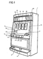
Fig. 1 is a perspective view of a slot machine according to the
embodiment;
Fig. 2 is an explanatory view showing a panel display part and a liquid
crystal display part;
Fig. 3 is an explanatory view showing an external appearance of a reel
mechanism in which lamps are arranged within each reel;
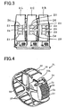
Fig. 4 is a perspective view showing a reel and a circuit board for
receiving LEDs therein arranged in the reel;
Fig. 5 is a perspective view roughly showing a construction of the
liquid crystal display device;
Fig. 6 is an exploded perspective view showing a part of the liquid
crystal display device;
Fig. 7 is an explanatory view for explaining function of the LED lamps
and fluorescent lamps;
Fig. 8 is a block diagram showing an electrical circuit in the
embodiment;
Fig. 9 is a block diagram showing a construction of a sub-control
circuit; and
Fig. 10 is an explanatory view showing demonstration display
contents.
Detailed Description of the Invention
Fig. 1 is a perspective view showing an outlined shape of a gaming
machine 1 according to one embodiment of the present invention. Here, the
gaming machine 1 is a so-called Japanese pachi-slot machine. Though, in
the gaming machine 1, a player plays games by using game media such as
coins, medals or tokens, or a card in which information of game value given
to the player is stored, it will be described hereinafter the gaming machine 1
in which medals are used.
Presently, the Japanese pachi-slot machine in the main current has a
plural kinds of winning modes. In particular, when a predetermined
winning combination is accepted, the player can obtain a more beneficial
gaming state than a normal gaming state for a predetermined period without
finishing the game by only one payout of medals. As such winning
combination, there exist one winning combination in which the game
relatively giving large benefit to the player can be done in predetermined
times (this winning combination is called "BIG BONUS" and abbreviated as
"BB" hereinafter) and another winning combination in which the game
relatively giving small benefit to the player in predetermined times (this
winning combination is called "REGULAR BONUS" and abbreviated "RB"
hereinafter).
And in the Japanese pachi-slot machine in the main current, in order
to materialize the winning combination that medals or coins are paid out
when a predetermined symbol combination stands side by side along pay
lines made activated (abbreviated as "activated line" hereinafter), it is
required to internally win the winning combination (abbreviated as "internal
winning" hereinafter) by the internal lottery treatment (abbreviated as
"internal lottery" hereinafter) and to conduct stop operation of the symbols by
the player at the timing that the symbol combination indicating the winning
combination internally won (abbreviated as "internal winning combination"
hereinafter) can stop along the activated lines. That is to say, even if the
winning combination is internally won, the winning according to the internal
winning combination cannot be realized when the stop operation by the
player is out of the timing. Namely, in the present Japanese pachi-slot
machine in the main current, it is required technique to conduct stop
operation of the symbols at good timing. This technique is called
"observation push", thus it is highly appreciated the technical intervention in
the present Japanese pachi-slot machine.
At the front surface of a cabinet 2 entirely forming the gaming
machine 1, a panel display unit 2a, a liquid crystal display unit 2b and a
fixed display unit 2c, which have substantially vertical planes, are formed.
As for the panel display unit 2a, the liquid crystal display unit 2b and the
fixed display unit 2c, they will be described with reference to Fig. 2,
hereinafter. In the cabinet 2 (at the rear side of the liquid crystal display
unit 2b), three reels 3L, 3C, 3R (the first display means comprising the game
result display means), on each outer periphery of which symbol line
comprising a plural kinds of symbols is described, are rotatably arranged
along a horizontal line. The reels 3L, 3C, 3R form the variable display
means. Symbols on each reel (rotational drum type display device) can be
seen through symbol display areas 21L, 21C, 21R (shown in Fig. 2
hereinafter). Each reel is constructed so as to be able to rotate at a constant
rotational speed (for example, 80 rotations / minute).
At a lower position of the panel display unit 2a, the liquid crystal
display unit 2b and the fixed display unit 2c, a frontward projection portion 4
having a substantially horizontal plane is formed. At the left side of the
frontward projection portion 4, it is arranged a BET switch 5 for betting
medals credited by button pressing operation. At the right side of the
frontward projection portion 4, a medal insertion slot 6 is formed. At the
front left side of the frontward projection portion 4, it is provided a c/p switch
7 for switching credit/payout of medals obtained in the game by the player
based on button pressing operation. On the basis of switching by the c/p
switch 7, medals are paid out from a medal payout opening 8 and the paid
medals are accumulated in a medal receiving tray 9.
At the right side of the C/P switch 7, a start lever 10 (game start
instruction means operable by the player), which starts rotation of the reels
when operated by the player and starts variable display of the symbols
(starts the game) within each of the symbol display areas 21L, 21C, 21R (see
Fig. 2), is provided so as to be able to rotate within a predetermined angle.
At the front center of the frontward projection portion 4 and the right side of
the start lever 10, three stop buttons 11L 11C, 11R (game result leading
means operable by the player), which is operated to stop rotation of the reels
3L, 3C, 3R, respectively, are arranged. At the upper left and right sides of
the cabinet 2, speakers 12L, 12R are arranged. Between the speakers 12L,
12R, a payout table panel 13 which shows winning combinations of the
symbols and the number of medals paid out as awards, is provided.
With reference to Fig. 2, the panel display unit 2a, the liquid crystal
display unit 2b and the fixed display unit 2c will be explained.
The panel display unit 2a comprises a bonus game information display
part 16, BET lamps 17a ~ 17c, a payout display part 18 and a credit display
part 19. Here, the bonus display part 16 is constructed from 7-segment
LEDs and displays the game information during the bonus game. The
1-BET lamp 17a, 2-BET lamp 17b and MAX-BET lamp 17c are turned on
according to the medal number betted to conduct the game. The 1-BET
lamp 17a is turned on when the betted medal number is "1". The 2-BET
lamp 17b is turned on when the betted medal number is "2". And the
MAX-BET lamp 17c is turned on when the betted medal number is "3". The
payout display part 18 and the credit display part 19 are constructed from
7-segment LEDs respectively. The payout display part 18 displays the
payout medal number when the winning is materialized. The credit display
part 19 displays the medal number accumulated (credited).
The liquid crystal display unit 2b comprises the symbol display areas
21L, 21C, 21R, window frame display areas 22L, 22C, 22R and effect display
area 23. The display contents displayed on the liquid crystal display 2b are
variably changed according to the variable symbol display mode of the reels
3L, 3C, 3R, stop display mode of the symbols and operation of a liquid crystal
display device 31 mentioned hereinafter.
The symbol display areas 21L, 21C, 21R are provided corresponding to
the reels 3L, 3C, 3R, respectively, and display the symbols arranged on the
outer periphery of the reels 3L, 3C, 3R and various effects thereon. Here, in
a case that the reels 3L, 3C, 3R corresponding to the symbol display areas
21L, 21C, 21R are rotating or the stop buttons 11L, 11C, 11R corresponding
to the symbol display areas 21L, 21C, 21R are in a operable state for stop
operation of the reels 3L, 3C, 3R, each symbol display area 21L, 21C, 21R is
transparently displayed so as to be able to easily recognize the symbols
arranged on the outer peripheries of the reels 3L, 3C, 3R, and effect effected
through still images or moving images by, for example, symbols, letters,
figures, marks, characters is not displayed.
The window frame display areas 22L, 22C, 22R are formed so as to
enclose each symbol display area 21L, 21C, 21R and represents the frames of
the symbols arranged on the outer peripheries of the reels 3L, 3C, 3R.
The effect display area 23 is formed in an area other than the symbol
display areas 21L, 21C, 21R and the window frame display areas 22L, 22C,
22R in the liquid crystal display unit 2b. This effect display area 23
displays the image (representing so-called "WIN LAMP") conclusively
indicating that bonus winning is realizable, the effect to increase interest for
games and the information necessary for the player to beneficially advance
the game.
The fixed display unit 2c is an area to display the images determined
beforehand. Concretely, the fixed display unit 2c displays" a part of row
houses" which is described on a display plate 33 mentioned hereinafter. By
combining the image displayed on the fixed display unit 2c and the image
displayed on the effect display area 23, one still image or moving image can
be displayed. In the embodiment, one complete image of the row houses can
be displayed.
Further, with reference to Figs. 3 and 4, LED lamps 29 arranged in the
reels 3L, 3C, 3R will be described. The LED lamps 29 function as
illumination means for illuminate the symbols arranged on the outer
peripheries of the reels 3L, 3C, 3R and one of illumination means for
illuminating the areas mainly corresponding to the symbol display areas 21L,
21C, 21R within an area of a liquid crystal panel 34 (mentioned later). Thus,
the LED lamps 29 function as common illumination means for commonly
illuminating the above symbols and the areas. And the LED lamps 29 also
function as rear illumination means for illuminating the first display means
from the backside thereof.
As shown in Fig. 3, in the reels 3L, 3C, 3R, there are arranged LED
receiving circuit boards 24 which are positioned behind the symbols of three
symbol lines (totally nine symbols), each symbol line appearing in each of
symbol display areas 21L, 21C, 21R when rotation of the reels 3L, 3C, 3R
stops. Each LED receiving circuit board 24 has three LED receiving
portions in each of which a plurality of LED lamps 29 are provided.
Hereinafter, among nine LED receiving portions, the LED receiving portion is
serially represented by Z1, Z2 and Z3 from the left portion in the horizontal
upper line, the LED receiving portion is serially represented by Z4, Z5 and Z6
from the left portion in the horizontal center line and the LED receiving
portion is serially represented by Z7, Z8 and Z9 from the left portion in the
bottom horizontal line. The LED lamp 29 illuminates the rear side of the
reel sheet by white light, the reel sheet being attached to the reel 3L, 3C, 3R
along the outer periphery thereof. The reel sheet is made translucent, thus
light emitted from the LED lamp 29 permeates to the front plane of the reel
sheet.
As shown in Fig. 4, the reel 3L is constructed from a cylindrical frame
construction in which two circular frames 25 and 26 with the same shapes
are connected by a plurality of connecting members 27 while separating with
a distance (corresponding to the reel width) therebetween, and transmitting
members 28 for transmitting driving force of a stepping motor 53L (see Fig.
8) arranged in the center position of the frame construction to the circular
frames 25 and 26. Here, the reel sheet attached to the outer periphery of
the reel 3L is omitted.
The LED receiving circuit board 24 arranged within the reel 3L has
three LED receiving portions Z1, Z4 and Z7, each receiving a plurality of
LED lamps 29. The LED receiving circuit board 24 is arranged so that the
LED receiving portions Z1, Z4, Z7 position at rear sides of the symbols
(totally three symbols), respectively, the symbols being seen through the
symbol display area 21L by the player. Here, though the reels 3C and 3R
are not shown, both reels have the same construction and the LED receiving
circuit board 24 is arranged within each reel.
Next, with reference to Figs. 5 and 6, a transmission type liquid crystal
display device 31 (corresponding to the second display means constructing the
game result display means) will be described. Fig. 5 is a perspective view
(seeing from the rear side of the cabinet 2) showing outline construction of
the liquid crystal display device 31. Fig. 6 is an exploded perspective view
showing a partial construction of the liquid crystal display device 31.
The liquid crystal display device 31 is constructed from a protect glass
32, a display plate 33, a liquid crystal panel 34, a light guide plate 35, a
reflection film 36, fluorescent lamps 37a, 37b, 38a, 38b functioning as
so-called white light sources (capable of emitting light including light having
all wavelengths with a predetermined ratio so that specific colors are
inconspicuous to eyes of persons), lamp holders 39a ~ 39h and a flexible
circuit board (not shown) comprising a table carrier package (TCP) mounting
an IC for driving the liquid crystal panel, the TCP being connected to a
terminal portion of the liquid crystal panel 34. The liquid crystal display
device 31 is arranged at a more front side than the display areas of the reels
3L, 3C, 3R (more front side than the display planes thereof) so as to spread
over the reels 3L, 3C, 3R. And the reels 3L, 3C, 3R and the liquid crystal
display device 31 are independently arranged (with a predetermined distance
therebetween).
The protect glass 32 and the display plate 33 are made of light
transmittable material. The protect glass 32 is provided with an object to
protect the liquid crystal panel 34. At the areas corresponding to the panel
display unit 2a of the display plate 33 and the fixed display unit 2c, images
are described. Here, various display parts positioned at the rear side of the
area in the display plate 33 corresponding to the panel display unit 2a and
electric circuits for operating the BET lamps 17a ~ 17c are omitted to show.
The liquid crystal panel 34 is formed by filling liquid crystal material
in clearance formed between the transparent plate such as a glass plate on
which thin film transistor layer is formed and the transparent plate facing
thereto. The display mode of the liquid crystal panel 34 is set to normally
white. Here, "normally white" means a construction that the liquid crystal
panel 34 becomes in a white display state (light can advance toward the
display plane, that is, light transmitted can be seen from outside) when the
liquid crystal panel 34 is not driven. By utilizing the liquid crystal panel 34
constructed to have the normally white mode, the symbols (variable display
and stop display of the symbol display parts) arranged on the reels 3L, 3C,
3R can be seen and recognized through the symbol display areas 21L, 21C,
21R even if it occurs a trouble that the liquid crystal panel cannot be driven.
Thereby, the player can continue the game. That is to say, if the above
trouble occurs, it can be conducted the game based on the basic function such
as the variable display and the stop display of the reels 3L, 3C, 3R.
The light guide plate 35 is arranged at the rear side of the liquid
crystal panel 34 in order to lead the light emitted from the luminescent
lamps 37a, 37b to the liquid crystal panel 34 (to illuminate the liquid crystal
panel). For example, the light guide plate 35 is constructed from the light
transmittable member with thickness of about 2 cm (having light
transmitting ability) made of acrylic resin.
As the reflection film 36, for example, it is used the member that silver
deposition layer is formed on white polyester film or aluminium thin film.
The reflection film 36 reflects light led to the light guide plate 35 toward the
front side thereof. This reflection film 36 is constructed from a reflection
area 36A and non-reflection areas (non-transmittable areas) 36BL, 36BC,
36BR. The non-reflection areas 36BL, 36BC, 36BR are formed as the light
transmittable areas which are made of transparent material and transmit
the light led thereto without reflecting, and are arranged at each front
position of symbols (totally three symbols) displayed when rotation of the
reels 3L, 3C, 3R is stopped. In this case, areas corresponding to the reel
sheet function as the light transmittable areas. Concretely, sizes and
positions of the non-reflection areas 36BL, 36BC, 36BR coincide with those of
the symbol display areas 21L, 21C, 21R. The reflection area 36A reflects the
light led thereto and functions as one of the illumination means for the area
mainly corresponding to the window frame display areas 22L, 22C, 22R and
the effect display area 23 within the area on liquid crystal panel 34.
According to the above construction, since the player can see and recognize
variable display and stop display of the symbols in the symbol display areas
through the light transmittable areas in reflection means, the player can
enjoy the game based on the display mode in the symbol display areas and
the liquid crystal display device.
The fluorescent lamps 37a and 37b are arranged along the upper edge
and the lower edge of the light guide plate 35 and both ends of the
fluorescent lamp 37a, 37b are supported by lamp holders 39. The
fluorescent lamps 37a and 37b function as illumination means for the area
mainly corresponding to the window frame display areas 22L, 22C, 22R and
the effect display area 23 within the area on the liquid crystal panel 34.
Namely, the fluorescent lamps 37a and 37b emit light led to the light guide
plate 35 (the lamps separately lead light to the light guide plate 35).
And the fluorescent lamps 38a and 38b are arranged so as to face
toward the reels 3L, 3C, 3R at the upper and lower positions on the rear side
of the reflection film 36. The light, which is emitted from the fluorescent
lamps 38a and 38b and reflected on the surface of the reels 3L, 3C, 3R,
further entered in the non-reflection areas 36BL, 36BC, 36BR, illuminates
the liquid crystal panel 34. Therefore, the fluorescent lamps 38a and 38b
function as the illumination means for illuminating the symbols arranged on
the reels 3L, 3C, 3R and one of the illumination means for the areas mainly
corresponding to the symbol display areas 21L, 21C, 21R within the area on
the liquid crystal panel 34. The fluorescent lamps 38a and 38b function as
common illumination means for illuminating both the above symbols and
areas. Further, the fluorescent lamps 38a and 38b also function as the
forward illumination means for illuminating the first display means from the
front side thereof.
As mentioned above, the first display means and the second display
means are commonly illuminated by the common illumination means. That
is to say, since not only the first display means but also the second display
means are illuminated by the light emitted from the common illumination
means, cost becomes cheaper than a case that the illumination means is
independently arranged for each display means. Further, by controlling the
common illumination means illumination control can made simple and the
same illumination for two display means can be also realized at the same
time.
Next, with reference to Fig. 7, function of the LED lamp 29 and the
fluorescent lamps 37a, 37b, 38a, 38b will be described. In Fig. 7, moving
direction of the emitted light from the lamp is shown by arrows.
Fig. 7 (1) schematically shows function of each lamp when the liquid
crystal existing at the symbol display areas 12L, 21C, 21R is not driven
(voltage is not added between the transparent plates of portions
corresponding to the symbol display areas in the liquid crystal panel 34).
A part of the light emitted from the fluorescent lamps 38a. 38b is
reflected on the reel sheet. And a part of the light emitted from the LED
lamps 29 arranged on the LED receiving circuit board 24 penetrates through
the reel sheet. Since the above light penetrates through the non-reflection
areas 36BL, 36BC, 36BR, the light guide plate 35 and the liquid crystal panel
36 both of which constructs the liquid crystal display device 31, the player
can see and recognize the symbols arranged on the reels. Therefore, in a
case that the liquid crystal existing at the symbol display areas 12L, 21C,
21R is not driven, the LED lamps 29 and the fluorescent lamps 38a, 38b
function as the illumination means for the symbols arranged on the reels 3L,
3C, 3R.
On the contrary, the light emitted from the fluorescent lamps 37a, 37b
and led into the light guide plate 35 penetrates through the liquid crystal
panel 34 and enters in eyes of the player. That is, the fluorescent lamps 37a,
37b function as the illumination means for the area in the liquid crystal
panel 34 corresponding to the above window frame display areas 22L, 22C,
22R and the effect display area 23.
Fig. 7 (2) schematically shows function of each lamp when the liquid
crystal existing at the symbol display areas 12L, 21C, 21R is driven (voltage
is added between the transparent plates of portions corresponding to the
symbol display areas in the liquid crystal panel 34).
A part of the light emitted from the fluorescent lamps 38a, 38b
is reflected on the reel sheet. And a part of the light emitted from the LED
lamps 29 penetrates through the reel sheet. Since a part of the above light
is reflected on or absorbed in or penetrated through the areas that the liquid
crystal is driven within the area of the liquid crystal panel 34, the player can
see and recognize the effect display and the like displayed on the symbol
display areas 21L, 21C, 21R. Therefore, in a case that the liquid crystal
existing at the symbol display areas 12L, 21C, 21R is driven, the LED lamps
29 and the fluorescent lamps 38a, 38b function as the illumination means
corresponding to the symbol display areas 21L, 21C, 21R within the area of
the liquid crystal panel 34.
Here, in a case that a part of the areas corresponding to the symbol
display areas 21L, 21C, 21R within the area of the liquid crystal panel 34 is
driven, the LED lamps 29 and the fluorescent lamps 38a, 38b function as the
illumination means for the symbols arranged on the reels 3L, 3C, 3R and as
the areas corresponding to the liquid crystal not driven in the symbol display
areas 21L, 21C, 21R within the liquid crystal panel 34.
Fig. 8 shows the circuitry construction including a main control circuit
41 for controlling game treatment operation in the gaming machine 1,
peripheral devices electrically connected to the main control circuit 41, and a
sub-control circuit 71 for controlling the liquid crystal display device 31 and
speakers 12L, 12R based on the control command transmitted from the main
control circuit 41. The main control circuit 41 and the sub-control circuit 71
construct the game result display control means. The main control circuit
41 has functions as the internal winning combination determination means,
the first display control means and the beneficial state producing means.
The internal winning combination determination means determines the
internal winning combination among plural winning combinations based on
the output from the game start instruction means. The first display
control means controls the first display means based on the determined
result by the internal winning combination determination means and the
output by the game result leading means. The beneficial state producing
means produces beneficial state for the player when a predetermined game
result is displayed on the game result display means. And the sub-control
circuit 71 controls the second display means based on the determined result
by the internal winning combination determination means and the output
from the game result leading means.
The main control circuit 41 is mainly constructed from a
microcomputer 42 arranged on the circuit board, in addition to a circuit for
sampling random number. The microcomputer 42 includes a CPU 43
conducting control operation according to preset program, a ROM 44 and a
RAM 45.
To the CPU 43, a clock pulse generator 46 generating reference clock
pulses, a frequency divider 47, a random number generator 48 for generating
random numbers sampled and a sampling circuit 49 are connected
respectively. Here, as the means for sampling random number, it may
construct that random number sampling is done according to the operation
program of the CPU 43 in the microcomputer 42. In this case, the random
number generator 48 and the sampling circuit 49 may be omitted, or these
may be remained to back up random number sampling operation.
In the ROM 44 of the microcomputer 42, there are stored a probability
lottery table utilized for judging random number sampling conducted every
operation of the start lever 10 (start operation), a stop control table for
determining stop combination of the reels according to operation of the stop
buttons and various control instructions (commands) to transmit to the
sub-control circuit 71. Here, the sub-control circuit 71 never transmits
commands, information and the like to the main control circuit 41, but
one-way transmission from the main control circuit 41 to the sub-control
circuit 71 is only done.
In the circuit of Fig. 8, as main actuators controlled based on control
signal from the microcomputer 42, there are various lamps (1-BET lamp 17a,
2-BET lamp 17b, MAX-BET lamp 17c), various display parts (bonus game
information display part 16, payout display part 18, credit display part 19), a
hopper 52 as the game value giving means (including drive part for payout)
accumulating medals and paying out a predetermined number of medals
according to instruction by a hopper drive circuit 51 and stepping motors 53L,
53C, 53R for driving the reels 3L, 3C, 3R to be rotated.
A motor drive circuit 54 for driving and controlling the stepping motors
53L, 53C, 53R, a hopper drive circuit 51 for driving and controlling the
hopper 52 and a lamp drive circuit 56 for driving and controlling various
lamps and a display drive circuit 56 for driving and controlling display parts
are connected to the output part of the CPU 43 through an I/O port 57.
These drive circuits controls operation in each of the actuators when
receiving control commands such as drive commands each of which is output
from the CPU 43.
Further, as for the input signal producing means mainly producing
input signals which are necessary for the microcomputer 42 to produce the
control commands, there are provided the BET switch 5, the medal sensor 6S
for detecting the inserted medals, the C/P switch 7, the start switch 10S, the
reel stop signal circuit 58, the reel position detecting circuit 59 and the
payout completion signal circuit 60. These are also connected to the CPU 43
through the I/O port 57.
The medal sensor 6S detects the medals inserted in the medal
insertion slot 6. The start switch 10S detects operation of the start lever 10.
The reel stop signal circuit 58 produces stop signal corresponding to
operation of each stop button 11L, 11C, 11R. The reel position detecting
circuit 59 provides signal to detect the position of each reel 3L, 3C, 3R with
the CPU 43 when receiving pulse signal from the reel rotation sensor. The
payout completion signal circuit 60 produces signal for detecting the medal
payout completion when the count number (corresponding to the medal
number paid out from the hopper 52) by the medal detection unit 52S reaches
to data of a designated number.
In the circuit shown in Fig. 8, the random number generator 48
generates random numbers within a predetermined numeral range and the
sampling circuit 49 conducts sampling of one random number at the suitable
timing after the start lever 10 is operated. Based on the thus sampled
random number and the probability lottery table stored in the ROM 44, the
internal winning combination of the symbols is determined. And after the
internal winning combination is determined, sampling of the random number
is conducted again to select the "stop control table".
After rotation of the reels 3L, 3C, 3R is started, it is counted the
number of the drive pulses each of which is provided with each of the
stepping motors 53L, 53C, 53R, and the counted number is written in the
predetermined area of the RAM 45. The reset pulse is generated from each
of the reels 3L, 3C 3R every one rotation thereof, and these reset pulses are
input to the CPU 43 through the reel position detecting circuit 59. Based on
the thus obtained reset pulses, the count number of drive pulses counted in
the RAM 45 is cleared to "0". Thereby, in the RAM 45, the count number
corresponding to the rotational position within one rotation in each of the
reels 3L, 3C, 3R is stored.
In order to connect the rotational positions of the reels 3L, 3C, 3R with
the symbols described on the outer peripheries of the reels, a symbol table is
stored in the ROM 44. In this symbol table, both code numbers, each of
which is serially given every a predetermined rotational pitch of each reel 3L,
3C, 3R by setting the rotational position producing the reset pulse as the
reference rotational position, and symbol codes, each of which indicates the
symbol provided corresponding to each of the code numbers, are connected
with each other.
Further, in the ROM 44, a winning symbol combination table is stored.
In the winning symbol combination table, winning symbol combinations
corresponding to various winnings, medal payout numbers each of which
corresponds to each winning and winning determination codes each of which
represents each winning, are corresponded with each other. The above
winning symbol combination table is referred when the stop control of the left
reel 3L, the center reel 3C and the right reel 3R is conducted and when the
winning is confirmed after all reels 3L, 3C, 3R are stopped.
When one of winning combinations is internally won by the lottery
treatment (probability lottery treatment) based on the above sampling of the
random number, the CPU 43 sends stop signals for conducting stop control of
the reels 3L, 3C, 3R to the motor drive circuit 54, based on the operation
signals sent from the reel stop signal circuit 58 at the timing that the player
operates the stop buttons 11L, 11C, 11R and the selected stop control table.
If the symbols stop in a stop mode that the winning combination
internally won is realized, the CPU 43 provides the payout command signal
to the hopper drive circuit 51, thereby a predetermined number of the medals
are paid out from the hopper 52. At that time, the medal detection unit 52S
counts the number of medals paid out, and when the number of medals paid
out reaches to the designated number, the medal payout completion signal is
input to the CPU 43. Thereby, the CPU 43 stops driving of the hopper 52
through the hopper drive circuit 51, as a result, the payout treatment of the
medals is terminated.
Fig. 9 shows a construction of the sub-control circuit 71. The
sub-control circuit 71 conducts turning on and off treatment of the LED
lamps 29 based on the control command from the main control circuit 41,
display control of the liquid crystal display device 31 and output control of
sounds output from the speakers 12L, 12R. This sub-control circuit 71 is
constructed on a separate circuit board from the circuit board on which the
main control circuit 41 is formed and is mainly constructed from a
microcomputer (abbreviated as "sub-microcomputer" hereinafter) 72. The
sub-control circuit 71 is constructed from a LED drive circuit 77 as the
display control means for controlling a plurality of ornamental lamps, the
LED lamps 29 and the fluorescent lamps 37a, 37b which are arranged on the
cabinet of the gaming machine 1, an image control circuit 81 as the display
control means of the liquid crystal display device 31, a sound source IC 78 for
controlling sounds output from the speakers 12L, 12R and a power amplifier
79 acting as the amplifier.
The sub-microcomputer 72 includes a sub-CPU 73 conducting control
operation according to the control command sent from the main control
circuit 41, a program ROM 74 acting as the memory means and a work RAM
75. Though the sub-control circuit 71 does not have the clock pulse
generator, the frequency divider, the random number generator and the
sampling circuit, it is constructed so that the random sampling is conducted
in the operation program of the sub-CPU 73. And the program ROM 74
stores the control program executed in the sub-CPU 73. Further, the
program ROM 74 also stores the image control program concerning with
display on the liquid crystal display device 31 and various select tables. The
work RAM 75 is constructed as the temporary memory means utilized when
the control program is executed by the sub-CPU 73.
The image control circuit 81 is constructed form an image control work
RAM 83, an image ROM 86, a video RAM 87 and an image control IC 82.
The image control IC 82 determines the display contents displayed on the
liquid crystal display device 31 based on parameters designated by the
sub-CPU 73. The image control work RAM 83 is used for temporarily
storing images when images are formed by the image control IC 82 and when
images followingly displayed on the liquid crystal display device 31 are
designated to the image control IC 82 by the sub-CPU 73. The image
control IC 82 forms images corresponding to display contents determined by
the sub-CPU 73 and outputs to the liquid crystal display device 31. The
image ROM 86 stores various images to form the images to be displayed.
And the video RAM 87 is constructed as the temporary memory means
utilized when images are formed in the image control IC 82.
Further, with reference to Fig. 10, display examples in the liquid
crystal display unit 2b will be described. Here, in the liquid crystal display
unit 2b of the embodiment, after it is continued for a predetermined time
interval (for example, one minute) a state (abbreviated "non-gaming state"
hereinafter) that medal inserting operation and operation of the BET switch
5 (abbreviated as "BET operation " hereinafter) are not conducted after one
game is finished (for example, rotation of all reels is stopped), demonstration
display (waiting image display) is basically conducted. This demonstration
display indicates a display for notifying a state that the gaming machine is in
a waiting state for the player. And existence or nonexistence of the
demonstration display and display patterns (modes) are changed according to
the internal winning combination and the like. Hereinafter,
"demonstration" is abbreviated as "demo".
Although detailed description will be explained later, the liquid crystal
display device 31 moves and displays visible areas ( fireworks 92, 93
mentioned later) on the liquid crystal panel, a part of the first display means
capable of being seen and recognized through the visible areas in cooperation
with the light transmittable part. This visible areas (light transmitting
symbols) have predetermined shapes (concretely, the shape indicating
"fireworks"). That is to say, it is provided in the second display means the
light transmitting symbols through which the player can see and confirm the
first display means and the light transmitting symbols can be variably
displayed, thereby display in the first display means and display in the
second display means can be mutually combined and displayed. Thus, it can
be done variegated effect display, which cannot be realized previously.
Further, since the light transmitting symbols have predetermined
shapes, the player can play games with more enjoyment than in previous
cases. And in a case that the predetermined shapes are symbols displayed
on the first display means, it can make the player have expectation to
occurrence of the beneficial state that a predetermined winning combination
or a specific winning combination may be materialized according to the
predetermined shapes.
And if it is constructed that the player can see and confirm a part of
the first symbol display part through the light transmitting symbols, the
player will play games with very high expectation when the player can see a
part of bonus winning symbol behind the light transmitting symbols.
Thereby, interest for games conducted in the game machine can be improved.
Here, the BET operation and start operation are conducted, and
"cherry small combination" is determined as the internal winning
combination. Further, the symbols are variably displayed on the symbol
display areas 21L, 21C, 21R and stop operation of the symbols is done.
Thereafter, as shown in Fig. 10 (1), the symbols are stopped and displayed on
the symbol display areas 21L, 21C, 21R. Here, "cherry small combination"
is materialized. In Fig. 10 (1), symbols on the reel sheet are partially
omitted to show. After stop display of the symbols is conducted and the
non-gaming state is continued for one minute, the "demo" display is done in
the effect display area 23 as shown in Fig. 10 (2). Concretely, two fireworks
91 and 92 are displayed in the effect display area 23 while moving. The
fireworks 91 are moved and displayed in the effect display area 23 and the
fireworks 92 are moved and displayed over the symbol display area 21R, the
window frame display area 22R and the effect display area 23. These
fireworks are moved and displayed based on moving images. Here, a part of
the reel sheet can be seen and recognized through the fireworks 92 displayed
on the symbol display area 21R.
Further, as shown in Fig. 10 (3), supposed that the center of the
fireworks 93 are positioned at the central part of the symbol display area 21C,
when the fireworks 93 are moved and displayed over the symbol display
areas 21L, 21C, 21R, the window frame display areas 22L, 22C, 22R and the
effect display area 23, the player can see and confirm a part of the symbol
(cherry symbol), which is stopped at the central part of the symbol display
area 21C, through a part indicating the fireworks 93.
As mentioned above, the visible area (the fireworks 92, 93), through
which the reel sheet as a part of the first display means can be seen and
recognized through the light transmittable part on the liquid crystal panel 34
by the liquid crystal display device 31, is moved and displayed. Thereby, it
can make the player have interest about what symbols are stopped and
displayed and interest for games can be raised. And since the visible area
has the shape indicating the fireworks, the player can enjoy the effect by the
displayed fireworks and it can make the player have interest about the
symbols and the like which can be seen and recognized through the shape
indicating the fireworks. Here, in the symbol display areas 21L, 21C, 21R, a
part of the shape in the fireworks 93 is indicated by white display. That is
to say, a part of the shape in the fireworks 93 is displayed by forming the
area in which the liquid crystal is not driven. And the player can clearly see
and recognize the symbol according to the shape indicating the fireworks by
providing the mentioned rear illumination means. Further, since the rear
illumination means illuminating the mentioned first illumination means from
the rear side thereof is provided, the player can clearly see and recognize the
display contents of the first display means, the contents being seen and
recognized through the light transmitting symbols, and it can make the
player have expectation that a predetermined beneficial state or a specific
beneficial state may occur, by combining the display contents of the first
display means with the shape of the light transmitting symbol.
Further, since the player is, in general, very interested in the mode of
symbols which are stopped and displayed, when the fireworks are moved and
displayed so as to be able to see and recognize the symbol, it can make the
player have more interest for games.
Though description is done according to the embodiment, the present
invention is not limited to this description.
The above mentioned second display means may be constructed from
the liquid crystal display device including the liquid crystal panel, the light
transmitting means arranged at the rear side of the liquid crystal panel,
individual illumination means for producing light entering in the light
transmitting means and the reflection means for reflecting light entered in
the light transmitting means toward the liquid crystal panel arranged at the
front side of the light transmitting means, and area in a part of the reflection
means may be made light transmittable, thereby the visible area through
which a part of the first display means can be seen and recognized through
the light transmittable part on the liquid crystal panel may be moved and
displayed.
Further, moving velocity of the above mentioned visible area (the
fireworks in the embodiment) may be differently changed. And a plurality
of the visible areas with different moving velocity may be provided and the
displayed visible area may be determined according to situations in the game.
Further, shape of the visible area may be changed or the visible area may be
moved and displayed while changing the shape thereof.
Further, the visible area may be moved and displayed based on a
predetermined operation by the player and the like persons (including clerk,
salesperson). And the visible area may be easily moved and displayed
according to the predetermined operation by the player. For example,
moving velocity, number, color, pattern, or shape (outline shape, inner shape)
of the visible area may be changed according to the predetermined operation
by the player, expectation value (information concerning with the game),
so-called stock number and the like.
Further, the visible area may be constructed so as to start of moving
and display thereof during variable displaying of the symbol display means
(the above mentioned reels), at substantially same timing of start of the
variable displaying, during stop displaying of the symbols and at
substantially same timing of stop displaying of the symbols.
Further, a plurality of the visible areas may be moved and displayed.
And these visible areas may have different moving velocity and shape,
respectively.
Further, it may be provided the light transmitting mode memory
means (for example, the image ROM 86) for storing a plurality of display
modes of images (for example, characters and the like) including the visible
area and the light transmitting mode select means (the sub-CPU 73) for
selecting one or plural display modes among the plural display modes stored
in the light transmitting mode memory means, the second display means may
display the image including the visible area based on the selected result by
the light transmitting mode select means. Thereby, various display modes
can be displayed and the player does not lose interest for the displayed
contents. As a result, interest for games can be more highly raised.
Further, since it is constructed so that display control of a plurality of
the light transmitting symbols can be done, variegated effect display can be
conducted. And in a case that the specific light transmitting symbol is
provided and when the specific winning combination is selected by the
winning combination select means the specific light transmitting symbol is
displayed with a more higher probability than a case that the specific
winning combination is not selected, the player plays games with very high
expectation when the specific light transmitting symbol is displayed, thereby
interest for games conducted in the game machine can be improved.
And in the embodiment, though the symbol display portions are formed
every reel which displays a plurality of symbols while rotating, the present
invention is not limited to this. For example, one symbol display area may
be formed in the second display means corresponding to one or plural or all of
plural reels (plural variable display parts) each of which displays a plurality
of symbols while rotating. Entire area of the second display means may
construct the symbol display area. The size thereof may be changed.
Further, it is enough that the symbol display area can display the
symbol of the first display means, and may be constructed from only member
capable of displaying symbols (transparent glass or transparent resin) in
which liquid crystal is not provided in the symbol display area.
The first display means or the third display means may be constructed
so as to be able to move in directions of up and down, right and left, before
and behind, reciprocally move, inducibly vibrate or rotate. In this case, the
symbol display part may be constructed so as to move according to the
movement of the first display means or the third display means. Based on
these operations, it can expect more interesting effect and there may be a
case that such operations are applicable for concerning with game contents.
It is enough for the symbol display area that the first display means or
the third display means can be seen therethrough.
And it is enough that the above mentioned light transmitting symbols
has a predetermined shape and the player can see and recognize the first
display means through the light transmitting symbol. Further, it may be
constructed that the light transmitting symbol is able to variably display by
enlargement, reduction or change in shape thereof. And the gaming
machine may be constructed so that a plurality of variable display modes can
be controlled to display and one or plural variable display modes are selected
among the above mentioned plural variable display modes according to the
winning combination selected by the winning combination select means, the
winning combination which is internally won but not materialized or random
number lottery and the like, and the light transmitting symbol is variably
displayed based on the selected variable display mode. In that case, the
player can see and recognize various light transmitting symbols themselves
or the symbols displayed on the first display means through the light
transmitting symbols. Thus, variegated effect display can be conducted and
thereby interest for games conducted in the gaming machine can be
improved.
Further, while variably displaying the light transmitting symbol, light
transmittability (easiness to see the first display means) thereof may be
varied. And the light transmitting symbol may have the same light
transmittability thereover and the light transmittability in plural stages.
As the concrete example, the light transmitting symbol may be constructed so
as to have high light transmittability (easier to see the first display means) at
circumferential part of the center thereof and low light transmittability
(harder to see the first display means) at a part according that such part is
apart from the circumferential part of the center thereof. Also in the thus
constructed case, variegated effect display can be conducted.
Further, the light transmittability of the light transmitting symbol
may be constructed so as to vary in time series (by stages or continuously
according to elapsing of time). In that case, velocity or direction in varying
of the light transmittability may be changed. Thereby, more profound effect
can be realized.
And the gaming machine may be constructed so that the light
transmittability of the light transmitting symbol is changed according to the
winning combination selected by the winning combination select means, the
winning combination which is internally won but not materialized or random
number lottery and the like. Substantially at the same time, movement and
size of the light transmitting symbol may be changed. Thereby, the player
see change in display of the light transmitting symbol while expecting
occurrence of the beneficial state, thus not only effect but also interest for
games can be improved.
And in the embodiment, though the reels 3L, 3C, 3R are adopted as
the first display means and the liquid crystal display device 31 is adopted as
the second display means, the present invention is not limited to this. For
example, CRT, LCD, plasma display, 7-segment LED, LED dot-matrix, lamp,
LED, fluorescent lamp, organic EL display, disc, electronic paper, flexible
LED, flexible liquid crystal, liquid crystal projector, FED and the like can be
adopted as the first display means, the second display means or the third
display means. Further, the third display means different from the first
display means and the second display means can be arranged at a more front
side than the second display means when seeing the front side of the gaming
machine, between the first display means and the second display means, or
at a more rear side than the first display means when seeing the front side of
the gaming machine. The display result displayed on the first display
means, the second display means or the third display means is constructed
from still images or moving images. The combination, in which two or more
or all of the first display means, the second display means and the third
display means are combined, can be integrally constructed. In this case,
there may be a case that the unit integrally constructed can be wholly
exchanged, and this case is preferable since time and labor for decomposing
work or assembling work thereof can be omitted and maintenance work can
be improved. Further, if parts and construction can be commonly used in
the unit, this case is preferable since it can contribute to cost reduction. Of
course, if the illumination means commonly utilizable for the common
illumination means is included in the unit, the same effect similar to the
above can be expected,
Further, the beneficial state includes: a state that a predetermined
combination (for example, replay, BB, RB, small combination, single bonus
and the like) is materialized; free game; a state that information necessary
for the player to favorably advance the game is notified; a state that
probability to get internal winning of a predetermined combination is high; a
state that winning of a predetermined combination is materialized with high
probability; winning of a predetermined combination or a predetermined
combination carried over is permitted to materialize with high probability;
so-called "challenge time" that the reels are basically stopped based on the
operation timing of the stop buttons by the player; small combination;
medium combination; big combination; combination (state that so-called
"symbol start opening" (symbol variable movement is started when a ball
enters in the symbol start opening) is opened or enlarged; so-called
"probability changing state", so-called "time shortening state"); or
combination of the above states. Here, the small combination, the medium
combination and the big combination concern with a state that so-called "big
winning opening" is opened in the so-called Japanese Pachinko gaming
machine.
And when the internal winning combination determination means
determines a predetermined combination (for example, bonus) as the internal
winning combination, one or plural or all of the illumination means included
in the common illuminations means can be turned off. For example, the
LED lamps 29 arranged for each of the reels 3L, 3C, 3R can be turned off
every the operation button corresponding thereto is operated or every the
operation button other than the above operation button is operated. Based
on the above constructions, interest for games increases. And the forward
illumination means (the fluorescent lamps 38a, 38b) can be provided for each
of the symbol display parts (the reel 3L, 3C, 3R).
Further, one or plural or all of the illumination means included in the
common illumination means can be constructed so as to variably display.
For example, still images or moving images can be displayed on the first
display means (reel sheet) by changing the turning on mode of the LED
lamps 29 or light colors emitted therefrom or by continuously changing those.
And self-emitting type plasma display, organic EL display and the like may
be adopted as the illumination means (one example of the third illumination
means), thereby images can be displayed on the first display means. By this
constructions, interest for games increases.
In a case that the special game result (for example, the symbol
combination indicating that bonus winning is materialized) is displayed on
the first display means or the second display means, it can be provided the
special gaming state producing means that the beneficial state for the player
is displayed thereon. And both the special gaming state producing means
and the second display means can be formed on single control circuit board.
And the gaming state can be displayed by superimposing the images
displayed on the first display means and the images displayed on the second
display means. Further, based on the trigger that a predetermined state is
realized, the effect display on the second display means can be done so as to
avoid the specific symbols stopped and displayed on the symbol display part
or so as to superimpose the specific symbols. If the gaming state is
displayed by the superimposed images, the beneficial state for the player may
be produced with high probability in comparison with the case in which the
superimposed images is not displayed. Thereby, it can include the effect
that the player's expectation increases, in excess of the previous case. Thus,
such effect can contribute to increase of interest.
In the embodiment, though the start lever 10 is adopted as the game
start instruction means, the present invention is not limited to this. For
example, the BET switch 5, the medal insertion slot 6, the medal sensor 6S
or the start switch 10S can be adopted.
The display includes: display by the sense of sight, display by the sense
of hearing, notification by the sense of smelling, turning on of the lamps or
combination of those. The display mode includes: colors, patterns, shapes
(outline shapes, interior shapes) and the like. And the game result can be
displayed after operation of the game start instruction means or the game
result leading means.
In the embodiment, though the above mentioned LED drive circuit is
utilized as the display control means for a plurality of the ornamental lamps,
the LED lamps and the fluorescent lamps, each of which is arranged in the
cabinet, the present invention is not limited to this. Turning on control of
the LED lamps may be conducted by another display control means. In this
case, for example, in turning on control of the LED lamps, electric power may
be provided so that the LED lamps are always turned on during a period
from power-on of the gaming machine till power-off thereof. Here, turning
on includes blinking mode that the LED lamps are intermittently blinked
with a very short time interval. Thus, since the LED lamps are always
turned on, light emitted from the LED lamps always illuminates each symbol
display area even if abnormality occurs in the mentioned LED drive circuit.
Thereby, the player can always see the symbols arranged on each of the reels
through the each symbol display areas, thus the above turning on control is
preferable.
Further, turning on control of the above mentioned fluorescent lamps
may be done by another display control means. In this case, for example, in
the turning on control of the fluorescent lamps, electric power may be
provided so that the fluorescent lamps are always turned on during a period
from power-on of the gaming machine till power-off thereof. Thereby,
similar to the above, light emitted from the fluorescent lamps always
illuminates each symbol display area even if abnormality occurs in the
mentioned LED drive circuit. Thereby, the player can always see and
recognize the symbols arranged on each of the reels through the each symbol
display areas
Further, in the embodiment, though the above mentioned sub-CPU
conducts display control of a plurality of the ornamental lamps arranged in
the cabinet, sound output control and image display control of the liquid
crystal display device, the present invention is not limited to this. Another
sub-CPU separate from the above sub-CPU may conduct the above various
controls. For example, in a case that another sub-CPU separate from the
above sub-CPU conducts the control of a plurality of the ornamental lamps
arranged in the cabinet and, for example, in a case that abnormality occurs
in the display control, it is enough to exchange only the sub-CPU with
abnormality occurrence or only the circuit construction including the
sub-CPU with abnormality occurrence to the normal sub-CPU or circuit
construction having the normal sub-CPU. Therefore, time and labor for
removing the cause of the abnormality occurrence can be omitted and such
construction is very preferable. And in a case that another sub-CPU other
than the above sub-CPU conducts sound output control or image display
control, or for example, in a case that abnormality occurs in the sound output
control or the image display control, it is enough to exchange only the
sub-CPU with abnormality occurrence or only circuit construction including
the sub-CPU with abnormality occurrence.
Further, the liquid crystal display device described in the embodiment
may have image enlarging means for enlarging the input images by a
predetermined magnification. For example, the image enlarging means may
convert the image data for 640 x 480 dots into the image data for 1024 x 768
dots and output the converted image data to the display part (above
mentioned terminal part). Thereby, it can use the image data for small
display area, the data quantity thereof being less in comparison with that for
the factual display area. As a result, memory quantity of the ROM and
image data forming time can be reduced.
And in the embodiment, though the symbol display area is divided
corresponding to each of three reels 3L, 3C, 3R, the present invention is not
limited to this and the symbol display area may be formed so as not to be
divided. For example, it may be conceivable that two or three of the reels
3L, 3C, 3R can be seen and recognized through one symbol display area.
And if the first display means and the third display means are arranged at
the rear face or side of the second display means, it may be constructed that
the player sees and recognizes through one symbol display area a part or
whole of the first display means and a part or whole of the third display
means. When the reflection means is produced, there may be a case that
the reflection means can be easily produced in comparison with a case that a
plurality of transparent portions are formed dividedly.
Further, the present invention can apply to Japanese Pachinko gaming
machine, arrange ball gaming machine, mah-jong ball gaming machine,
video-slot machine, video poker machine and the other machines, in addition
to the slot machine in the embodiment. And even in the game program
imitatively executing operation of the above mentioned slot machine in a
family gaming machine, the present invention can apply and execute the
game. In this case, CD-ROM, FD (flexible disc) and the similar memory
medium can be utilized for the memory medium for storing the game
program.
Here, recently in the Japanese Pachinko gaming machine in the main
current, the gaming machine, in which an electric display device such as the
liquid crystal display device is arranged at the center of gaming plate, is
popularized. In this electric display device, a plurality of symbols
(abbreviated as "special symbols" hereinafter) represented by images are
variably displayed, thereby three lines of reels in the slot machine are
imitatively displayed. When variable display of the special symbols stops
and a predetermined stop mode (in which the same special symbols stop such
as 7-7-7 and this stop mode is generally called "big combination"), the game
shifts to the special gaming state beneficial for the player. In general
Japanese Pachinko gaming machine, the variable display of the special
symbols is started on condition that balls shot within the gaming plate by
operation of the shooting handle enter into a predetermined winning hole
(so-called "variable display start hole"). After a predetermined time is
elapsed the variable display of the special symbols stops.
In this kind of Japanese Pachinko gaming machine, it may be arranged
the liquid crystal display device (the second display means) and the first
display means (for example, drum-type reels) at a more rear side than the
display area (display plane) of the liquid crystal display device when seeing
the front side of the gaming machine. And the special symbols may be
variably displayed on one or both of the first display means (for example, the
liquid crystal display device) and the second display means (for example,
drum-type reels).
The above mentioned game result display means may be constructed so
as to include the first display means and the second display means provided
at a more front side than the display area of the first display means when
seeing the front surface of the gaming machine. And the game result
display means may be constructed so as to include the first display means
and the second display means provided at a more front side than the display
area of the first display means when seeing the front side of the gaming
machine.
The above mentioned rear illumination means illuminates the second
display means from the backside thereof. And the above mentioned front
illumination means illuminates the second display means from the backside
of thereof. And the front illumination means may illuminate the second
display means from the side plane thereof.
The above mentioned first display means and/or the second display
means may be formed in a curved shape. As for extent of the curvature, the
first display means and the second display means may have substantially the
same curvature. Thereby, there may be a case that design of the gaming
machine is improved and the gaming machine is made attractive. Even if
the first display means is curved with a small radius of curvature or with a
large radius of curvature, the above same effect can be obtained.
The above mentioned reflection means corresponds to means which has
at least function to refract a part or whole of light led by the light leading
means toward the liquid crystal panel and illuminate the liquid crystal panel.
The above mentioned game start instruction means may be a variable
symbol display start hole which produces an output signal when the winning
combination or passage of the ball is detected. The game start instruction
means in the ball flipping machine corresponds to the variable display start
hole for the special symbols (or the start gate), the variable display start hole
for the common symbols, the various judging symbol display start holes (or
the start gates).
In a case that the above mentioned internal winning combination
determination means determines the predetermined combination as the
internal winning combination, one or plural illumination means included in
the common illumination means is/are turned off. Or the illumination
means may always be turned off.
There may be a case that one or plural illumination means included in
the common illumination means is/are turned off at the substantially same
timing that the above mentioned internal winning combination determination
means determines the predetermined combination as the internal winning
combination. Or the illumination means may always be turned off.
As for variable display by the illumination means included in the
common illumination means, it is conceivable various display modes. For
example, it may be constructed so as to be able to execute the special symbol
variable display. Here, the special symbol variable display can be executed
in the mode such as: brightness in a part or whole of the display part in the
illumination means differs from that in the non-specific symbol variable
display; still images, moving images, specific letters, numbers, figures,
characters, which are not displayed in the non-specific symbol variable
display, are displayed; variable display speed differs from that in the
non-specific symbol variable display. Further, voluntary display modes may
be utilized. And in a case that the specific symbol variable display is
conducted, it may be constructed that the beneficial state for the player
occurs with high probability in comparison with the case that the specific
symbol variable display is not done. Thereby, it can be included the effect
that the player's expectation increases, in excess of the previous case. Thus,
such effect can contribute to increase of interest.
As for the means adopted as the third display means, it may be
adopted display devices which is applicable as the first display means and the
second display means, as mentioned above. It may be a case that one or
plural effect display reels is/are utilized as the third display means, and both
the first display means and the third means are arranged at the rear surface
or side of the second display means. In this case, the symbol display area
through which the player sees the display area of the third display means
may be provided in the second display means. Thereby, the player can
easily recognize the display contents on the display area of the third display
means, thus this construction is very preferable.
Further, it may be controlled so that the images formed by
superimposing the images of the second display means and the images of the
third display means are seen by the player, and when such control occurs, the
beneficial state occurs with higher probability than the case that such control
does not occur. Thereby, it can be included the effect that the player's
expectation increases, in excess of the previous case. Thus, such effect can
contribute to increase of interest.
Further, any one of the first display means, the second display means
and the third display means may be constructed form a movable structure
with shapes such as figures, dolls, animals, insects, famous structures, fishes,
vehicles. For example, the above structures may be moved with rotation,
swing, reciprocal movement or vibration in cases that: the special
combination is internally won, the special combination is materialized, the
number of the combination which is as same as the special combination
internally won but not materialized exceeds a predetermined number, the
special images are displayed on the display means different from the above
structures. And there may be a case that the above structure is constructed
from plural members and a part of the members is/are moved. In this case,
there may be a case that it can be further expected more various effects by
displaying on other than the image display device.
Further, the front illumination means may be arranged at the front
side of the first display means and the second display means. In this case, if
the inside of the game arcade is dark, the front illumination means can
illuminate both the first display means and the second display means with
enough light. Therefore, there may be a case that the player can clearly
recognize the images displayed on the display means, thus it can be expected
that the player can enjoy more various effect in the gaming machine.
Although only some exemplary embodiments of this invention have
been described in detail above, those skilled in the art will readily
appreciated that many modifications are possible in the exemplary
embodiments without materially departing from the novel teachings and
advantages of this invention. Accordingly, all such modifications are
intended to be included within the scope of this invention.