TECHNICAL FIELD
-
The present invention relates generally to a
communication apparatus and a band control method,
and particularly to a communication apparatus for
constructing a virtual group formed by a portion of
information appliances implemented over a network.
BACKGROUND ART
-
In a network constructed by the Ethernet
(registered trademark) such as a LAN, virtual LAN
(VLAN) technology may be used to construct a virtual
group with a portion of information appliances
(stations) provided in a LAN.
-
In the VLAN technology, a physical network
structure and a logical network structure are
separated so that stations residing over physically
separate segments may be grouped into one virtual
segment. Such VLAN technology is defined by the
IEEE 802.1Q standard, and presently, two types of
VLAN technology exist, namely, the port VLAN and the
tag VLAN.
-
Port VLAN involves assigning LAN numbers to the
ports of bridge apparatuses such as switching hubs,
and arranging traffic flow such that each port only
receives traffic designated for its corresponding
group with its corresponding VLAN number. Port VLAN
enables separation of traffic into physical ports,
and may therefore be suitable for fields such as
security and network management.
-
Tag VLAN involves attaching two bytes of
information called a 'VLAN tag' to a frame, and
setting a VLAN number (VLAN ID) for identifying the
group to which the frame belongs. Tag VLAN enables
plural groups to share one physical link. The VLAN
tag is used as an identifier for identifying a
corresponding group of a frame.
-
In recent years and continuing, application of
the Ethernet to a metropolitan area network (MAN) is
being contemplated. Such a MAN may be constructed
by an electronic communications company (carrier) to
provide network service to a user.
-
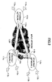
FIG.1 illustrates an exemplary configuration of
an Ethernet service scheme in a MAN. In the MAN
shown in FIG.1, a virtual group (user A) is made up
of stations 102a~102c, which constitute a portion of
a LAN constructed by the Ethernet (to be simply
referred to as Ethernet network hereinafter).
-
In the present example, a VLAN tag is assigned
to user A so that bridge apparatuses 100a~100c and
101 within the Ethernet network may use the VLAN tag
to realize frame transmission between the stations
102a~102c. The VLAN tag is used as an identifier to
identify a corresponding group of a user (i.e.
subscriber), and in this way, band and other QoS
(quality of service) may be provided to a given
group according to its VLAN tag.
-
Also, technology exists for connecting plural
Ethernet networks by an MPLS (Multiprotocol Label
Switching) network, such technology being referred
to as EoMPLS (Ethernet over MPLS). EoMPLS involves
attaching an identifier called a 'label' to a frame
within an MPLS network, and conducting frame
transmission based on this label.
-
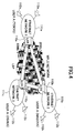
FIG.2 shows an exemplary configuration of an
EoMPLS network. In the example of FIG.2, a virtual
group is made up of stations 112a~112c corresponding
to portions of Ethernet networks 111a~111c,
respectively. The Ethernet networks 111a~111c are
interconnected by an LSP (Label Switch Path) within
the MPLS network. The Ethernet networks 111a~111c
are connected to the MPLS via LER (Label Edge
Router) 110a~110c, respectively.
-
In the present example, an LSP may be
established between the Ethernet networks 111a~111c
by using EoMPLS technology, and thereby, a desired
band may be secured as a reserved band in each LSP
to realize band control betweeen the Ethernet
networks 111a~111c.
-
However, in the case of an Ethernet service
scheme in a MAN as is illustrated in FIG.1, the VLAN
tag is used as an identifier for identifying a
corresponding group of a user, and consequently,
problems such as those described below are created.
-
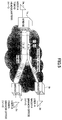
Referring to FIG.3, if user A subscribes to an
Ethernet service at three different locations,
namely, Tokyo headquarters, Nagoya branch office,
and Osaka branch office, for example, the reserved
band is equally distributed between these locations.
In a WAN as illustrated in FIG.3, the group
corresponding to user A may be identified by the
VLAN tag; however, the respective locations of the
group may not be identified and thereby band usage
may not be controlled with respect to the different
locations.
-
For example, if the reserved band corresponds
to 100 Mb/s, it is not possible to control usage of
the band so that 80 Mb/s may be used between the
Tokyo headquarters and the Osaka branch office and
20 Mb/s between the Tokyo headquarters and the
Nagoya branch office. In other words, in the
present example, the bridge apparatuses 100a~100c
and 101 are merely capable of handling traffic as
that designated for user A and are unable to
recognize the different locations belonging to the
group of user A.
-
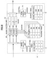
Referring to FIG.4, in the case of using EoMPLS
technology as is illustrated in FIG.2, an LSP may be
established between the Ethernet networks, and a
desired band may be set as the reserved band for
each LSP so that band usage between the respective
locations (base) may be suitably controlled.
-
For example, if the reserved band is 100 Mb/s,
band usage may be controlled so that 80 Mb/s is used
between the Tokyo head quarters and the Osaka branch
office, and 20 Mb/s is used between the Tokyo head
quarters and the Nagoya branch office.
-
However, the MPLS network requires complicated
network designing. Also, in the EoMPLS technology,
the frame being transmitted over the Ethernet
network is encapsulated by the frame being
transmitted over the MPLS network, thereby resulting
in a large overhead.
DISCLOSURE OF THE INVENTION
-
The present invention has been conceived in
response to the one or more problems of the related
art and its object is to provide a communication
apparatus and a band control method for enabling
band control of bases within a virtual group that is
constructed by a portion of information appliances
provided over a network.
-
To achieve the above-described object, the
present invention, according to one aspect, provides
a communication apparatus that constructs a virtual
group with a portion of information appliances
provided over a network, the apparatus including:
- a tag attaching unit configured to attach to a
frame received at an input port a group
identification tag for identifying the group to
which the frame belongs and a route identification
tag for identifying a route of the frame;
- a queue configured to store the frame according
to the group identification tag and the route
identification tag attached to the frame;
- a read control unit configured to control a
read rate for reading the frame from the queue.
-
-
In a communication apparatus according to an
aspect of the present invention, a group
identification tag and a route identification tag
are attached to a frame and band control may be
realized according to the route identification tag.
Thereby, band control may be easily conducted for
the respective bases of a virtual group formed by a
portion of information appliances provided over a
network.
-
According to a preferred embodiment of the
present invention, the communication apparatus of
the present invention further includes:
- a traffic flow control unit configured to
control traffic flow of the frame to be stored in
the queue according to the group identification tag
attached to the frame;
wherein the frame is stored in the queue
according to the route identification tag attached
to the frame.-
-
In a communication apparatus according to the
present embodiment, traffic flow of a frame to be
stored in a queue may be controlled for each group
identification tag and frames with the same route
may be stored in the same queue so that the number
of queues may be reduced.
-
According to another preferred embodiment of
the present invention, the traffic flow control unit
is configured to control a maximum flow of the frame
to be stored in the queue according to the group
identification tag attached to the frame.
-
In a communication apparatus according the
present embodiment, the maximum flow of a frame to
be stored in a queue may be controlled for each
group identification tag so that band resources may
be fairly distributed among differing groups of
frames within a given queue.
-
According to another preferred embodiment of
the present invention, the traffic control unit is
configured to control a maximum flow and a minimum
flow of the frame to be stored in the queue
according to the group identification tag attached
to the frame.
-
In a communication apparatus according to the
present embodiment, the minimum flow and the maximum
flow of a frame to be stored in a queue may be
controlled for each group identification tag.
Thereby, a minimum band may be secured for each
corresponding group of a frame that is stored in a
given queue, while an unused band that is secured
for a group may be allotted to another group.
-
According to another preferred embodiment of
the present invention, when the traffic flow of the
frame is greater than or equal to the minimum flow
and is less than or equal to the maximum flow, the
traffic flow control unit attaches to the frame an
indicator for indicating that the frame is to be
discarded with priority upon congestion of the queue.
-
In a communication apparatus according to the
present embodiment, a frame with a traffic flow that
is greater than or equal to a minimum flow and is
less than or equal to a maximum flow may be
discarded with priority upon congestion of a queue,
and thereby, a frame of a group that is assigned a
band having a traffic flow below the minimum flow
rate may be read with priority.
-
According to another preferred embodiment of
the present invention, the route identification tag
is attached to a position corresponding to a
position in the frame to which the group
identification tag is attached prior to the
attachment of the route identification tag.
-
In a communication apparatus according to the
present embodiment, a route identification tag is
attached to a frame at a position corresponding to
where a group identification tag is previously
positioned, and thereby, a function of the
communication apparatus of transferring a frame
according to its group identification tag may be
used to transmit a frame to another communication
apparatus according to the route identification tag
attached to the frame.
-
Also, the present invention, according to
another aspect, provides a communication apparatus
that constructs a virtual group with a portion of
information appliances provided over a network, the
apparatus comprising:
- a tag removing unit configured to remove from a
frame received at an input port a route
identification tag for identifying a route of the
frame; and
- an output unit configured to read from the
frame a group identification tag for identifying the
group to which the frame belongs and output the
frame to an output port according to the group
identification tag.
-
-
In a communication apparatus according to an
aspect of the present invention, a route
identification tag is removed from a frame having a
group identification tag and a route identification
tag attached thereto, and thereby, a frame that is
converted back to its original state may be output
to an output port.
-
Also, the present invention, according to
another aspect, provides a band control method for
controlling a communication apparatus that
constructs a virtual group with a portion of
information appliances provided over a network, the
method comprising:
- a tag attaching step of attaching to a frame
received at an input port a group identification tag
for identifying the group to which the frame belongs
and a route identification tag for identifying a
route of the frame;
- a buffering step of storing the frame in a
queue according to the group identification tag and
the route identification tag attached to the frame;
and
- a reading step of reading the frame from the
queue according to a read rate set for the queue.
-
-
In a band control method according to an aspect
of the present invention, a group identification tag
and a route identification tag are attached to a
received frame to realize band control based on the
route identification tag of a frame. Thereby, band
control may be easily realized for the respective
bases of a virtual group formed by a portion of
information appliances provided over a network.
-
Also, the present invention, according to
another aspect, provides a band control method for
controlling a communication apparatus that
constructs a virtual group with a portion of
information appliances provided over a network, the
method comprising:
- a tag removing step of removing from a frame
received at an input port a route identification tag
for identifying a route of the frame; and
- an outputting step of reading from the frame a
group identification tag for identifying the group
to which the frame belongs and outputting the frame
to an output port according to the read group
identification tag.
-
-
In a band control method according to an aspect
of the present invention, a route identification tag
is removed from a frame having a group
identification tag and a route identification tag
attached thereto, and thereby, a frame that is
converted back to its original state may be output
to an output port.
BRIEF DESCRIPTION OF THE DRAWINGS
-
Other objects, features and advantages of the
present invention will become more apparent from the
following detailed description when read in
conjunction with the accompanying drawings.
- FIG.1 is a diagram showing an exemplary scheme
of an Ethernet service in a MAN;
- FIG.2 is a diagram showing an exemplary
configuration of an EoMPLS network;
- FIG.3 is a diagram illustrating a band control
scheme of an Ethernet service in a MAN;
- FIG.4 is a diagram showing a band control
scheme for controlling the bands between bases
provided over an EoMPLS network;
- FIG.5 is a diagram showing a configuration of
an Ethernet network implementing bridge apparatuses
as communication apparatuses according to an
embodiment of the present invention;
- FIG.6 is a diagram showing an exemplary
configuration of a bridge apparatus according to an
embodiment of the present invention;
- FIG.7 is a diagram showing a configuration of a
queue control unit according to a first embodiment
of the present invention;
- FIG.8 is a diagram showing a configuration of a
queue control unit according to a second embodiment
of the present invention;
- FIG.9 is a diagram showing a configuration of a
queue control unit according to a third embodiment
of the present invention;
- FIG.10 is a diagram showing a configuration of
a queue control unit according to a fourth
embodiment of the present invention;
- FIG.11 is a diagram illustrating an exemplary
operation of the bridge apparatus upon receiving a
non-learned frame; and
- FIG.12 is a diagram showing an exemplary
configuration of another bridge apparatus according
to an embodiment of the present invention.
-
BEST MODE FOR CARRYING OUT THE INVENTION
-
In the following, preferred embodiments of the
present invention are described with reference to
the accompanying drawings.
-
FIG.5 shows an exemplary configuration of a
network using communication apparatuses according to
an embodiment of the present invention; more
specifically, FIG.5 shows an exemplary Ethernet
network using bridge apparatuses. In the following
description, an example is described in which a user
A having base points at Tokyo headquarters, Nagoya
branch office, and Osaka branch office establishes
connection by assigning 20 Mb/s between the Tokyo
headquarters and the Nagoya branch office and 80
Mb/s between the Tokyo headquarters and the Osaka
branch office.
-
In a case where user A subscribes to Ethernet
service at three locations; namely, the Tokyo
headquarters, the Nagoya branch office, and the
Osaka branch office, station 3a at the Tokyo
headquarters, station 3b at the Nagoya branch office,
and station 3c at the Osaka branch office form a
virtual group.
-
As is shown in the drawing, station 3a is
connected to a bridge apparatus 1a; station 3b is
connected to a bridge apparatus 1b, and station 3c
is connected to a bridge apparatus 1c. The bridge
apparatuses 1a~1c are interconnected via a bridge
apparatus 2.
-
According to the present embodiment, a first
VLAN tag V1 for identifying a user group and a
second VLAN tag V2 for identifying a frame route are
assigned to a frame being transmitted between two of
the bridge apparatuses 1a~1c. In FIG.5, VLAN tag
V1=1 is set for the group corresponding to user A,
VLAN tag V2=3 is set for the route between the Tokyo
headquarters and the Nagoya branch office, and VLAN
tag V2=5 is set for the route between the Tokyo head
quarters and the Osaka branch office. It is noted
that in FIG.5, frames being transmitted between two
of the bridge apparatuses 1a~1c are only represented
by their VLAN tags V1 and V2, and other components
of these frames are omitted from the drawing for the
sake of simplicity.
-
For example, in the case of a port VLAN, a
frame transmitted from station 3a of the Tokyo
headquarters may be supplied to the bridge apparatus
1a. In turn, the bridge apparatus 1a may attach to
this frame a VLAN number 1 that is assigned to the
port receiving the frame as a VLAN tag V1.
-
In the case of a tag VLAN, a frame transmitted
from the station 3a at the Tokyo headquarters is
supplied to the bridge apparatus 1a after a VLAN tag
V1 is attached to the frame at a prior stage
apparatus.
-
Then, the bridge apparatus 1a attaches a VLAN
tag V2 to the frame according to the route of the
received frame having a VLAN tag V1 attached thereto.
For example, a frame that is to be transmitted from
station 3a to station 3b may have a VLAN tag V1=1
and a VLAN tag V2=3 attached thereto, and a frame
that is to be transmitted from station 3a to station
3c may have a VLAN tag V1=1 and a VLAN tag V2=5
attached thereto.
-
Then, the bridge apparatus 1a stores (buffers)
the frame with the VLAN tags V1 and V2 attached
thereto in a queue according to the VLAN tags V1 and
V2. In the example shown in FIG.5, the VLAN tag V1
and V2 are attached to a frame within the bridge
apparatus 1a; however, other embodiments are
possible in which plural bridge apparatuses are used
to attach the VLAN tags V1 and V2 to a frame, for
example.
-
It is noted that band control for the queues
storing frames according to their VALN tags may be
realized by WRR (Weighted Round Robin). For example,
a frame stored in a queue for a VLAN tag V1=1 and a
VLAN tag V2=3 may be read at 20 Mb/s, whereas a
frame stored in a queue for a VLAN tag V1=1 and a
VLAN tag V2=5 may be read at 80 Mb/s. A frame that
is read from a queue according to the band set in a
manner described above may then be transmitted to
the bridge apparatus 2.
-
In the present example, a frame transmitted
from the bridge apparatus 1a is received at a tag
VLAN port of the bridge apparatus 2. The bridge
apparatus 2 is arranged to identify the route of a
received frame by referring to its outermost VLAN
tag, namely, its VLAN tag V2. It is noted that the
bridge apparatus is arranged to identify a domain of
a frame by simply referring to the outermost VLAN
tag of a frame, and the present embodiment uses such
feature of the bridge apparatus to identify the
route of a frame. More specifically, by stacking a
VLAN tag V2 on a VLAN tag V1 so that the VLAN tag V2
is positioned at an outermost edge of a frame, the
bridge apparatus 2 may identify the route of a frame
by simply referring to the outer most VLAN tag V2 of
a received frame without recognizing the existence
of two stacks of tag information.
-
The bridge apparatus 1b or 1c is arranged to
receive a frame from the bridge apparatus 2 and
remove the second VLAN tag V2 from the received
frame. In the case of the port LAN, the bridge
apparatus 1b or 1c removes the VLAN tag V2 and then
the VLAN tag V1 from the frame, and transmits the
resulting frame to the corresponding station 3b or
3c. In the case of the tag VLAN, the bridge
apparatus 1b or 1c removes the VLAN tag V2 after
which it transmits the frame to a subsequent
apparatus where the VLAN tag V1 may be removed.
Then, the resulting frame is transmitted to the
corresponding station 3b or 3c.
-
FIG.6 shows an exemplary configuration of the
bridge apparatus 1a. According to the present
example, the bridge apparatus 1a includes a VLAN tag
V1 attaching unit 10, a MAC search unit 11, a queue
control unit 12, at least one queue 13, a write
control unit 14, a read control unit 15, and a MAC
table 16. It is noted that in the example of FIG.6,
only a VLAN tag V1, a VLAN tag V2, a DA (destination
address), and a SA (source address) of a frame
passing through the bridge apparatus 1a are
indicated, and other components of the frame are
omitted from the drawing for the sake of simplicity.
-
In the example of FIG.5 in which the station 3a
is directly connected to the bridge apparatus 1a and
the VLAN corresponds to a port VLAN, the VLAN tag V1
attaching unit 10 attaches a VLAN tag V1 to a frame
received from the station 3a and transmits the frame
with the VLAN tag V1 to the MAC search unit 11.
-
On the other hand, when the station 3a is not
directly connected to the bridge apparatus 1a in
which case the VLAN corresponds to a tag VLAN, a
frame having a VLAN tag V1 attached thereto in a
prior stage apparatus is transmitted to the MAC
search unit 11.
-
According to the present example, the MAC
search unit 11 is arranged to read the DA and the
VLAN tag V1 of a received frame, and access a MAC
table 16 to search for a corresponding VLAN tag V2
and a port to which the frame is to be output using
the DA and the VLAN tag V1 as key information. The
MAC table 16 indicates the correspondence between a
DA, a VLAN tag V1, a port, and a VLAN tag V2. After
determining the corresponding VLAN tag V2 and output
port, the MAC search unit 11 attaches the
corresponding VLAN tag V2 to the received frame and
transmits this frame to the queue control unit 12.
-
In turn, the write control unit 14 included in
the queue control unit 12 reads the VLAN tags V1 and
V2 from the received frame, and searches for a queue
13 to which the frame is to be stored based on the
VLAN tags V1 and V2 as is described in detail below.
Then, the queue control unit 12 stores the frame in
the corresponding queue 13.
-
The read control unit 15 included in the queue
control unit 12 searches for a corresponding read
rate for reading the frame. It is noted that a
predetermined read rate may be set for each queue,
so that a frame may be read from its corresponding
queue 13 at a corresponding read rate. In this way,
the queue control unit 12 is able to control a frame
read rate for each queue.
-
In the following, the operation of the queue
control unit 12 is described in greater detail.
-
FIG.7 is a diagram showing a configuration of a
queue control unit 12 according to a first
embodiment of the present invention. In the example
of FIG.7, the queue control unit 12 includes at
least one queue 13, a write control unit 14, a read
control unit 15, a queue allotting table 17, and a
shaping table 18.
-
In the present example, the write control unit
14 of the queue control unit 12 is arranged to read
the VLAN tags V1 and V2 of a received frame, and
access the queue allotting table 17 to search for a
corresponding queue 13 using the VLAN tags V1 and V2
as key information. The queue allotting table 17
indicates a correspondence between VLAN tags V1 and
V2 and a queue. After determining the corresponding
queue 13 based on the VLAN tags V1 and V2, the write
control unit 14 stores the received frame in the
corresponding queue 13.
-
In the example of FIG.7, different queues 13
are provided for different combinations of the VLAN
tags V1 and V2. Thus, the queue control unit 12
allots a received frame according to its VLAN tags
V1 and V2.
-
Also, in the present example, the read control
unit 15 of the queue control unit 12 is arranged to
search for a corresponding read rate for a queue 13
from the shaping table 18 and read a frame from the
queue 13 at the corresponding read rate. In this
way, the queue control unit 12 may be able to
control a frame read rate for each queue 13.
-
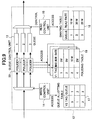
FIG.8 is a diagram showing a configuration of a
queue control unit 12 according to a second
embodiment of the present invention. The queue
control unit 12 of FIG.8 includes at least one queue
13, a write control unit 14, a read control unit 15,
a queue allotting table 17, a shaping table 18, a
policing table 19, and at least one policer 20.
-
According to the present example, the write
control unit 14 of the queue control unit 12 is
arranged to read the VLAN tag V2 of a received frame
and access the queue allotting table 17 to search
for a corresponding queue for the frame using the
VLAN tag V2 as key information. The queue allotting
table 17 indicates a correspondence between a VLAN
tag V2 and a queue 13. The queue control unit 12
allots a received frame to a corresponding queue 13
according to its VLAN tag V2; namely, its route.
-
In an arrangement according to the present
example, policing of traffic flow is conducted with
respect to each VLAN tag V1; namely, for each group,
so that a particular group may be prevented from
dominating the read band. The queue control unit 12
of FIG.8 includes a policer 20 before each queue 13
to conduct policing of a frame being stored in each
queue 13 to thereby control the traffic flow of a
frame according to its VLAN tag V1.
-
The policer 20 is arranged to read the VLAN tag
V1 of a received frame and access the policing table
19, which indicates a correspondence between a VLAN
tag V1 and an input rate, to determine a
corresponding input rate for the received frame
using the read VLAN tag V1 as key information. It
is noted that the policing table 19 may be
individually set for each policer 20. In this way,
the queue control unit 12 may allot a received frame
according to its VLAN tag V2 and control the traffic
flow of the allotted frame according to its VLAN tag
V1.
-
After the policing conducted by the policer 20,
a frame that is allotted according to its VLAN tag
V2 may be stored in its corresponding queue 13. It
is noted that in the example of FIG.8, different
queues 13 are provided with respect to different
VLAN tags V2, and thereby, the number of queues to
be provided in the queue control unit 12 may be
reduced compared to the example of FIG.7.
-
Also, in the present example, the read control
unit 15 of the queue control unit 12 is arranged to
access the shaping table 18 to search for a
corresponding read rate for a frame from the
respective read rates set to the queues 13 in the
shaping table 18, and read the frame from its
corresponding queue 13 at the corresponding read
rate. In this way, the queue control unit 12 is
able to control a frame read rate for each queue 13.
-
FIG.9 is a diagram showing a configuration of a
queue control unit 12 according to a third
embodiment of the present invention. In the queue
control unit 12 of FIG.9 the shaping table 18 and
the policing table 19 are set differently from the
example of FIG.8.
-
Specifically, in FIG.9, the policing table 19
indicates a maximum rate for each VLAN tag or each
group. Accordingly, the policer 20 conducts
policing of a frame to be stored in a queue 13
according to a maximum rate set for the
corresponding group of the frame referring to the
policing table 19. In the shaping table 18 of the
present example, the sum of the maximum rates for
the corresponding groups of frames stored in a queue
13 is set as the read rate of the queue 13.
-
By setting the sum of the maximum rates of the
corresponding groups of the frames stored in a queue
13 as the read rate of the queue 13 in the shaping
table 18, traffic passing through a corresponding
policer 20 may be transmitted without being
discarded.
-
For example, in a case where frames belonging
to groups of users A and B are stored in the same
queue 13, if the maximum rate set for the group of
user A is 50 Mb/s, and the maximum rate set for the
group of user B is 80 Mb/s, the read rate of the
corresponding queue 13 is set to 130 Mb/s in the
shaping table 18.
-
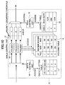
FIG.10 is a diagram showing a configuration of
a queue control unit 12 according to a fourth
embodiment of the present invention. In the queue
control unit 12 of FIG.10, the shaping table 18 and
the policing table 19 are set differently with
respect to the examples of FIGS.8 and 9.
-
According to the present example, the policing
table 19 sets a minimum rate and a maximum rate for
each VLAN tag V1; namely, for each group. The
policer 20 is arranged to conduct policing of a
frame to be stored in a queue 13 according to the
minimum rate and the maximum rate for the
corresponding group of the frame set in the policing
table 19. In this example, traffic with flow rate
that is within the range between the minimum rate
and the maximum rate (best effort traffic) has a
priority discarding bit set thereto so as to be
discarded with priority in its corresponding queue
13.
-
Also, in each queue 13, a priority discarding
threshold value is set, and when traffic in a queue
13 exceeds the priority discarding threshold value,
a frame with the priority discarding bit may be
discarded with priority. By giving priority for
discarding a frame having a priority discarding bit
over other frames, traffic below the minimum rate
may be read with priority when traffic in a queue 13
exceeds the priority discarding threshold value.
-
For example, in the case where frames belonging
to groups of users A and B are stored in the same
queue 13, if the maximum rate and minimum rate for
the group of user A are set to 50 Mb/s and 20 Mb/s,
respectively, and the maximum rate and the minimum
rate set for the group of user B are 80 Mb/s and 20
Mb/s, respectively, the read rate for the queue 13
is set to 30~130 Mb/s in the shaping table 18. It
is noted that a high read rate set in the shaping
table 18 enables efficient passage of the best
effort traffic while a low read rate tends to
degrade the passage of the best effort traffic.
-
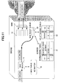
In the following, an operation of the bridge
apparatus 1a in response to receiving a non-learned
frame is described with reference to FIG.11.
-
FIG.11 is a diagram illustrating an exemplary
operation of the bridge apparatus 1a in response to
receiving a non-learned frame. It is noted that
basic operation steps conducted in the present
example are identical to those described in relation
to the example of FIG.6, and their descriptions are
omitted accordingly.
-
In the present example, the MAC search unit 11
reads the DA and the VLAN tag V1 of a received frame
and accesses the MAC table 16 to search for a
corresponding VLAN tag V2 and a port to which the
frame is to be output using the read DA and the VLAN
tag V1 as key information. In the present example,
the received frame corresponds to a non-learned
frame, and thereby, the MAC search unit 11 is unable
to find the corresponding VLAN tag V2 and the port
to which the frame is to be output from the MAC
table 16.
-
In such a case, the MAC search unit accesses a
forwarding table 31 using the VLAN tag V1 of the
received frame as key information to acquire a bit
map of the physical and logical ports belonging to
the VLAN tag V1 so that it may multicast the frame
to the VLAN tag V1 domain. In such an operation,
the frame may be accumulated in a multicast queue 30
to wait for a readout opportunity to each port.
-
When a readout opportunity is granted, a
corresponding VLAN tag V2 for the queue from which a
frame is to be read is read out from the VLAN tag
attaching table 32. In this way, a read control
unit may be able to transmit a frame with a VLAN tag
V2 attached thereto even when the frame is received
as a non-learned frame.
-
FIG.12 is a diagram showing an exemplary
configuration of the bridge apparatuses 1b and 1c.
According to the present example, the bridge
apparatuses 1b and 1c each include a MAC learning
unit 40, a VLAN tag V2 removing unit 41, a MAC
search unit 42, a VLAN tag V1 removing unit 43, and
a MAC table 44. It is noted that in FIG.12, only
the VLAN tag V1, the VLAN tag V2, the DA, and the SA
are indicated in the frame passing through the
bridge apparatus 1b or 1c, and the rest of the
components of the frame are omitted from the
drawings for the sake of simplicity.
-
According to the present example, upon
receiving a frame from the bridge apparatus 2, the
MAC search unit 40 of the bridge apparatus 1b or 1c
is arranged to read the VLAN tag V1, the VLAN tag V2,
and the SA of the received frame, learn the
correspondence between the SA, the VLAN tag V1, the
port receiving the frame, and the VLAN tag V2, and
store the learned information in the MAC table 44.
-
It is noted that the MAC table 44 associates a
set of the SA and the VLAN tag V1 with a set of the
corresponding output port and the VLAN tag V2.
After storing the learned information, the MAC
leaning unit 40 transmits the learned frame to the
VLAN tag V2 removing unit 41. In turn, the VLAN tag
V2 removing unit removes the VLAN tag V2 from the
received frame and transmits the resulting frame to
the MAC search unit 42.
-
The MAC search unit 42 is arranged to read the
VLAN tag of a received frame, and access the MAC
table 44 to determine a corresponding port to which
the frame is to be output using the VLAN tag V1 as
key information.
-
If the corresponding port is a port VLAN, the
VLAN tag V1 removing unit 43 receives the frame from
the MAC search unit 42, removes the VLAN tag V1 from
the received frame, and transmits the resulting
frame to the corresponding station 3b or 3c. On the
other hand, if the corresponding port is a tag VLAN,
the MAC search unit 42 of the bridge apparatus 1b or
1c transmits the frame with the VLAN tag V2 removed
therefrom to a subsequent apparatus where the VLAN
tag V1 may be removed. Then, the resulting frame is
transmitted to the corresponding station 3b or 3c.
-
Further, it is noted that the present invention
is not limited to the specific embodiments described
above, and variations and modifications may be made
without departing from the scope of the present
invention.