EP1569360A1 - Spread-spectrum system and method - Google Patents
Spread-spectrum system and method Download PDFInfo
- Publication number
- EP1569360A1 EP1569360A1 EP05010690A EP05010690A EP1569360A1 EP 1569360 A1 EP1569360 A1 EP 1569360A1 EP 05010690 A EP05010690 A EP 05010690A EP 05010690 A EP05010690 A EP 05010690A EP 1569360 A1 EP1569360 A1 EP 1569360A1
- Authority
- EP
- European Patent Office
- Prior art keywords
- power
- cell
- mobile unit
- site
- signal
- Prior art date
- Legal status (The legal status is an assumption and is not a legal conclusion. Google has not performed a legal analysis and makes no representation as to the accuracy of the status listed.)
- Withdrawn
Links
Images


Classifications
-
- H—ELECTRICITY
- H04—ELECTRIC COMMUNICATION TECHNIQUE
- H04W—WIRELESS COMMUNICATION NETWORKS
- H04W52/00—Power management, e.g. TPC [Transmission Power Control], power saving or power classes
- H04W52/04—TPC
-
- H—ELECTRICITY
- H04—ELECTRIC COMMUNICATION TECHNIQUE
- H04B—TRANSMISSION
- H04B1/00—Details of transmission systems, not covered by a single one of groups H04B3/00 - H04B13/00; Details of transmission systems not characterised by the medium used for transmission
- H04B1/69—Spread spectrum techniques
- H04B1/707—Spread spectrum techniques using direct sequence modulation
-
- H—ELECTRICITY
- H03—ELECTRONIC CIRCUITRY
- H03G—CONTROL OF AMPLIFICATION
- H03G3/00—Gain control in amplifiers or frequency changers without distortion of the input signal
- H03G3/20—Automatic control
- H03G3/30—Automatic control in amplifiers having semiconductor devices
- H03G3/3036—Automatic control in amplifiers having semiconductor devices in high-frequency amplifiers or in frequency-changers
- H03G3/3042—Automatic control in amplifiers having semiconductor devices in high-frequency amplifiers or in frequency-changers in modulators, frequency-changers, transmitters or power amplifiers
- H03G3/3047—Automatic control in amplifiers having semiconductor devices in high-frequency amplifiers or in frequency-changers in modulators, frequency-changers, transmitters or power amplifiers for intermittent signals, e.g. burst signals
-
- H—ELECTRICITY
- H04—ELECTRIC COMMUNICATION TECHNIQUE
- H04B—TRANSMISSION
- H04B1/00—Details of transmission systems, not covered by a single one of groups H04B3/00 - H04B13/00; Details of transmission systems not characterised by the medium used for transmission
- H04B1/69—Spread spectrum techniques
- H04B1/707—Spread spectrum techniques using direct sequence modulation
- H04B1/7097—Interference-related aspects
- H04B1/711—Interference-related aspects the interference being multi-path interference
- H04B1/7115—Constructive combining of multi-path signals, i.e. RAKE receivers
- H04B1/712—Weighting of fingers for combining, e.g. amplitude control or phase rotation using an inner loop
-
- H—ELECTRICITY
- H04—ELECTRIC COMMUNICATION TECHNIQUE
- H04B—TRANSMISSION
- H04B7/00—Radio transmission systems, i.e. using radiation field
- H04B7/005—Control of transmission; Equalising
-
- H—ELECTRICITY
- H04—ELECTRIC COMMUNICATION TECHNIQUE
- H04J—MULTIPLEX COMMUNICATION
- H04J13/00—Code division multiplex systems
-
- H—ELECTRICITY
- H04—ELECTRIC COMMUNICATION TECHNIQUE
- H04J—MULTIPLEX COMMUNICATION
- H04J13/00—Code division multiplex systems
- H04J13/0003—Code application, i.e. aspects relating to how codes are applied to form multiplexed channels
-
- H—ELECTRICITY
- H04—ELECTRIC COMMUNICATION TECHNIQUE
- H04J—MULTIPLEX COMMUNICATION
- H04J13/00—Code division multiplex systems
- H04J13/16—Code allocation
-
- H—ELECTRICITY
- H04—ELECTRIC COMMUNICATION TECHNIQUE
- H04W—WIRELESS COMMUNICATION NETWORKS
- H04W52/00—Power management, e.g. TPC [Transmission Power Control], power saving or power classes
- H04W52/04—TPC
- H04W52/06—TPC algorithms
- H04W52/08—Closed loop power control
-
- H—ELECTRICITY
- H04—ELECTRIC COMMUNICATION TECHNIQUE
- H04W—WIRELESS COMMUNICATION NETWORKS
- H04W52/00—Power management, e.g. TPC [Transmission Power Control], power saving or power classes
- H04W52/04—TPC
- H04W52/18—TPC being performed according to specific parameters
- H04W52/22—TPC being performed according to specific parameters taking into account previous information or commands
- H04W52/221—TPC being performed according to specific parameters taking into account previous information or commands using past power control commands
-
- H—ELECTRICITY
- H04—ELECTRIC COMMUNICATION TECHNIQUE
- H04W—WIRELESS COMMUNICATION NETWORKS
- H04W52/00—Power management, e.g. TPC [Transmission Power Control], power saving or power classes
- H04W52/04—TPC
- H04W52/18—TPC being performed according to specific parameters
- H04W52/22—TPC being performed according to specific parameters taking into account previous information or commands
- H04W52/225—Calculation of statistics, e.g. average, variance
-
- H—ELECTRICITY
- H04—ELECTRIC COMMUNICATION TECHNIQUE
- H04W—WIRELESS COMMUNICATION NETWORKS
- H04W52/00—Power management, e.g. TPC [Transmission Power Control], power saving or power classes
- H04W52/04—TPC
- H04W52/18—TPC being performed according to specific parameters
- H04W52/22—TPC being performed according to specific parameters taking into account previous information or commands
- H04W52/228—TPC being performed according to specific parameters taking into account previous information or commands using past power values or information
-
- H—ELECTRICITY
- H04—ELECTRIC COMMUNICATION TECHNIQUE
- H04W—WIRELESS COMMUNICATION NETWORKS
- H04W52/00—Power management, e.g. TPC [Transmission Power Control], power saving or power classes
- H04W52/04—TPC
- H04W52/30—TPC using constraints in the total amount of available transmission power
- H04W52/36—TPC using constraints in the total amount of available transmission power with a discrete range or set of values, e.g. step size, ramping or offsets
- H04W52/362—Aspects of the step size
-
- H—ELECTRICITY
- H04—ELECTRIC COMMUNICATION TECHNIQUE
- H04W—WIRELESS COMMUNICATION NETWORKS
- H04W52/00—Power management, e.g. TPC [Transmission Power Control], power saving or power classes
- H04W52/04—TPC
- H04W52/52—TPC using AGC [Automatic Gain Control] circuits or amplifiers
-
- H—ELECTRICITY
- H04—ELECTRIC COMMUNICATION TECHNIQUE
- H04B—TRANSMISSION
- H04B1/00—Details of transmission systems, not covered by a single one of groups H04B3/00 - H04B13/00; Details of transmission systems not characterised by the medium used for transmission
- H04B1/69—Spread spectrum techniques
- H04B1/707—Spread spectrum techniques using direct sequence modulation
- H04B1/709—Correlator structure
- H04B1/7093—Matched filter type
-
- H—ELECTRICITY
- H04—ELECTRIC COMMUNICATION TECHNIQUE
- H04B—TRANSMISSION
- H04B2201/00—Indexing scheme relating to details of transmission systems not covered by a single group of H04B3/00 - H04B13/00
- H04B2201/69—Orthogonal indexing scheme relating to spread spectrum techniques in general
- H04B2201/707—Orthogonal indexing scheme relating to spread spectrum techniques in general relating to direct sequence modulation
- H04B2201/70707—Efficiency-related aspects
-
- H—ELECTRICITY
- H04—ELECTRIC COMMUNICATION TECHNIQUE
- H04J—MULTIPLEX COMMUNICATION
- H04J13/00—Code division multiplex systems
- H04J13/10—Code generation
-
- H—ELECTRICITY
- H04—ELECTRIC COMMUNICATION TECHNIQUE
- H04W—WIRELESS COMMUNICATION NETWORKS
- H04W52/00—Power management, e.g. TPC [Transmission Power Control], power saving or power classes
- H04W52/04—TPC
- H04W52/30—TPC using constraints in the total amount of available transmission power
- H04W52/36—TPC using constraints in the total amount of available transmission power with a discrete range or set of values, e.g. step size, ramping or offsets
- H04W52/367—Power values between minimum and maximum limits, e.g. dynamic range
-
- H—ELECTRICITY
- H04—ELECTRIC COMMUNICATION TECHNIQUE
- H04W—WIRELESS COMMUNICATION NETWORKS
- H04W52/00—Power management, e.g. TPC [Transmission Power Control], power saving or power classes
- H04W52/04—TPC
- H04W52/54—Signalisation aspects of the TPC commands, e.g. frame structure
Definitions
- the present application relates communication systems. More specifically, the present invention relates to a novel and improved method and apparatus for controlling transmitter power in a code division multiple access (CDMA) cellular mobile telephone system.
- CDMA code division multiple access
- CDMA code division multiple access
- TDMA time division multiple access
- FDMA frequency division multiple access
- AM modulation schemes such as amplitude companded single sideband (ACSSB)
- CDMA has significant advantages over these other techniques.
- TDMA time division multiple access
- FDMA frequency division multiple access
- AM modulation schemes such as amplitude companded single sideband (ACSSB)
- CDMA has significant advantages over these other techniques.
- TDMA time division multiple access
- FDMA frequency division multiple access
- ACSB amplitude companded single sideband
- the use of CDMA techniques in a multiple access communication system is disclosed in U.S. Patent Application Serial No. 06/921,261, filed October 17, 1986, entitled "SPREAD SPECTRUM MULTIPLE ACCESS COMMUNICATION SYSTEM USING SATELLITE OR TERRESTRIAL REPEATERS", now U.S. Patent No. 4,901,307 assigned to the assignee of the present invention, the disclosure thereof incorporated by
- a multiple access technique is disclosed where a large number of mobile telephone system users each having a transceiver communicate through satellite repeaters or terrestrial base stations (also known as cell-sites stations, or for short cell-sites) using code division multiple access (CDMA) spread spectrum communication signals.
- CDMA code division multiple access
- the frequency spectrum can be reused multiple times thus permitting an increase in system user capacity.
- the use of CDMA results in a much higher spectral efficiency than can be achieved using other multiple access techniques.
- increases in system capacity may be realized by controlling the transmitter power of each mobile user so as to reduce interference to other system users.
- the mobile unit transceiver measures the power level of a signal received via a satellite repeater. Using this power measurement, along with knowledge of the satellite transponder downlink transmit power level and the sensitivity of the mobile unit receiver, the mobile unit transceiver can estimate the path loss of the channel between the mobile unit and the satellite. The mobile unit transceiver then determines the appropriate transmitter power to be used for signal transmissions between the mobile unit and the satellite, taking into account the path loss measurement, the transmitted data rate and the satellite receiver sensitivity.
- the signals transmitted by the mobile unit to the satellite are relayed by the satellite to a Hub control system earth station.
- the Hub measures the received signal power from signals transmitted by each active mobile unit transceiver.
- the Hub determines the deviation in the received power level from that which is necessary to maintain the desired communications.
- the desired power level is a minimum power level necessary to maintain quality communications so as to result in a reduction in system interference.
- the Hub transmits a power control command signal to each mobile user so as to adjust or "fine tune” the transmit power of the mobile unit.
- This command signal is used by the mobile unit to change the transmit power level closer to a minimum level required to maintain the desired communications.
- both the mobile unit receiver power measurement and the power control feedback from the Hub continually readjust the transmit power level so as to maintain a proper power level.
- the power control feedback from the Hub is generally quite slow due to round trip delays through the satellite requiring approximately 1/2 of a second of propagation time.
- satellite or terrestrial base stations systems One important difference between satellite or terrestrial base stations systems are the relative distances separating the mobile units and the satellite or cell-site. Another important different in the satellite versus the terrestrial system is the type of fading that occurs in these channels. Thus, these differences require various refinements in the approach to system power control for the terrestrial system.
- the satellite repeaters are normally located in a geosynchronous earth orbit. As such, the mobile units are all at approximately the same distance from the satellite repeaters and therefore experience nearly the same propagation loss. Furthermore, the satellite channel has a propagation loss characteristic that follows approximately the inverse square law, i.e. the propagation loss is inversely proportional to the square of the distance between the mobile unit and the satellite repeater in use. Accordingly, in the satellite channel the variation in path loss due to distance variation is typically on the order of only 1-2 dB.
- the terrestrial/mobile unit channel i.e. the terrestrial channel
- the distance between the mobile units and the cell sites can vary considerably. For example, one mobile unit may be located at a distance of five miles from the cell site while another mobile unit may be located only a few feet away. The variation in distance may exceed a factor of one hundred to one.
- the terrestrial channel experiences a propagation loss characteristic as did the satellite channel.
- the propagation loss characteristic corresponds to an inverse fourth-power law, i.e. the path loss is proportional to the inverse of the path distance raised to the fourth power. Accordingly, path loss variations may be encountered which are on the order of over 80 dB in a cell having a radius of five miles.
- the satellite channel typically experiences fading that is characterized as Rician. Accordingly the received signal consists of a direct component summed with a multiply reflected component having Rayleigh fading statistics.
- the power ratio between the direct and reflected component is typically on the order of 6-10 dB, depending upon the characteristics of the mobile unit antenna and the environment about the mobile unit.
- the terrestrial channel experiences signal fading that typically consists of the Rayleigh faded component without a direct component.
- the terrestrial channel presents a more severe fading environment than the satellite channel where Rician fading is the dominant fading characteristic.
- the Rayleigh fading characteristics in the terrestrial channel signal is caused by the signal being reflected from many different features of the physical environment. As a result, a signal arrives almost simultaneously at a mobile unit receiver from many directions with different transmission delays.
- UHF frequency bands usually employed for mobile radio communications including those of cellular mobile telephone systems, significant phase differences in signals traveling on different paths may occur. The possibility for destructive summation of the signals may result, with on occasion deep fades occurring.
- Terrestrial channel fading is a very strong function of the physical position of the mobile unit. A small change in position of the mobile unit changes the physical delays of all the signal propagation paths, which further results in a different phase for each path. Thus, the motion of the mobile unit through the environment can result in a quite rapid fading process. For Example, in the 850 MHz cellular radio frequency band, this fading can typically be fast as one fade per second per mile per hour of vehicle speed. Fading on this order can be extremely disruptive to signals in the terrestrial channel resulting in poor communication quality. However, additional transmitter power can be used to overcome the problem of fading.
- the terrestrial cellular mobile telephone system typically requires a full-duplex channel to be provided in order to allow both directions of the telephone conversation to be simultaneously active such as provided by the conventional wired telephone system.
- This full-duplex radio channel is normally provided by using one frequency band for the outbound link, i.e. transmissions from the cell-site transmitter to the mobile unit receivers.
- a different frequency band is utilized for the inbound link, i.e. transmissions from the mobile unit transmitters to the cell-site receivers. According, this frequency band separation allows a mobile unit transmitter and receiver to be active simultaneously without feedback or interference from the transmitter into the receiver.
- the mobile phone is capable of communications through multiple cell-sites as disclosed in U.S. Patent No. 5,101,501 issued March 31, 1992, entitled “METHOD AND SYSTEM FOR PROVIDING A SOFT HANDOFF IN COMMUNICATIONS IN A CDMA CELLULAR TELEPHONE SYSTEM", the disclosure of which is incorporated by reference.
- the mobile unit and cell-sites include a multiple receiver scheme as disclosed in the just mentioned patent and further detailed in U.S. Patent No. 5,109,390 issued April 28, 1992, entitled “DIVERSITY RECEIVER IN A CDMA CELLULAR TELEPHONE SYSTEM", the disclosure of which is also incorporated by reference.
- mobile phone transmitter power In the cell diversity environment in which the mobile phone is communicating with another user through multiple cell-sites, mobile phone transmitter power must also be controlled so as to avoid adverse interference with other communications in all cells.
- an object of the present invention to provide a novel and improved method and apparatus for controlling transmitter power in the terrestrial channel in a cell diversity environment so as to overcome deleterious fading without causing unnecessary system interference which can adversely affect overall system capacity.
- the transmitter power of the mobile units be controlled so as to produce at the cell site receiver a nominal received signal power from each and every mobile unit transmitter operating within the cell. Should all of the mobile unit transmitters within an area of coverage of the cell-site have transmitter power controlled accordingly the total signal power received at the cell-site would be equal to the nominal receiver power of the mobile unit transmitted signal multiplied by the number of mobile units transmitting within the cell. To this is added the noise power received at the cell-site from mobile units in adjacent cells.
- the CDMA receivers of the cell-site respectively operate by converting a wideband CDMA signal from a corresponding one of the mobile unit transmitters into a narrowband digital information carrying signal. At the same time, other received CDMA signals that are not selected remain as wideband noise signals.
- the bit-error-rate performance of the cell-site receiver is thus determined by the ratio of the power of the desired signal to that of the undesired signals received at the cell-site, i.e., the received signal power in the desired signal transmitted by the selected mobile unit transmitter to that of the received signal power in undesired signals transmitted by the other mobile unit transmitters.
- the bandwidth reduction processing a correlation process which results in what is commonly called “processing gain" increases the signal to noise interference ratio from a negative value to a positive value thus allowing operation within an acceptable bit-error-rate.
- System capacity can be maximized if the transmitter power of each mobile unit is controlled such that the transmitted signal arrives at the cell-site receive at the minimal signal to noise interference ratio which allows acceptable data recovery. If a signal transmitted by a mobile unit arrives at the cell-site receiver at a power level that is too low, the bit-error-rate may be too high to permit high quality communications. On the other hand if the mobile unit transmitted signal is at a power level that is too high when received at the cell-site receiver, communication with this particular mobile unit will be acceptable. However, this high power signal acts as interference to other mobile unit transmitted signals that are sharing the same channel, i.e. bandwidth. This interference may adversely affect communications with other mobile units unless the total number of communicating mobile units is reduced.
- the path loss of signals in the UHF frequency band of the cellular mobile telephone channel can be characterized by two separate phenomena, average path loss and fading.
- the average path loss can be described statistically by a log-normal distribution whose mean is proportional to the inverse fourth- power of the path distance, and whose standard deviation is approximately equal to 8 dB.
- the second phenomena is a fading process caused by multipath propagation of the signals which is characterized by a Rayleigh distribution.
- the average path loss which is a log-normal distribution, can be considered to be the same for both the inbound and outbound frequency bands, as is for the conventional cellular mobile telephone systems.
- Rayleigh fading is an independent phenomena for the inbound and outbound link frequency bands.
- the log-normal distribution of the average path loss is a relatively slow varying function of position. In contrast, the Rayleigh distribution varies relatively fast as a function of position.
- a CDMA approach to multiple user access in a cellular mobile telephone system is implemented.
- all the cell-sites in a region transmit a "pilot" signal of the same frequency and code.
- the use of a pilot signal in CDMA systems is well known.
- the pilot signal is used by the mobile units for initial synchronization of the mobile unit receiver.
- the pilot signal is also used as a phase and frequency reference, and a time reference for demodulation of the digital speech signals transmitted by the cell-site.
- each mobile unit estimates the path loss in signals transmitted from the cell-site to the mobile unit.
- the power level of the cell-site transmitted signals, as received at the mobile unit are measured.
- the mobile unit thus measures the pilot signal power as received from the cell-site to which the mobile unit is communicating.
- the mobile unit also measures the power level sum of all cell-site transmitted signals as received at the mobile unit. The power level sum measurement as described in further detail later herein, is necessary to handle cases in which the mobile unit might temporarily obtain a better path to a more distant cell-site than to a normally preferred closest cell-site.
- the outbound link path loss estimate may be filtered using a non-linear filter.
- the purpose of the non-linearity in the estimation process is to permit a rapid response to a sudden improvement in the channel while only allowing a much slower response to a sudden degradation in the channel.
- the mobile unit in response to a sudden improvement in the channel thus suddenly reduces mobile unit transmitter transmit power.
- a typical example of a sudden improvement in the channel occurs when a mobile unit is moving through an area that is shadowed by a large building or other obstruction and then drives out of the shadow.
- the channel improvement as a result of the vehicle movement, can take place on the order of a few tens of milliseconds.
- the outbound link signal as received by the mobile unit will suddenly increase in strength.
- the outbound link path loss estimate at the mobile unit is used by the mobile unit to adjust the mobile unit transmitter power.
- the stronger the received signal the lower the mobile unit transmitter power will be.
- Reception of a strong signal from the cell-site indicates that the mobile unit is either close to the cell-site or else an unusually good path to the cell-site exists. Reception of a strong signal means that a relatively smaller mobile unit transmitter power level is required in nominal received power at the cell-site the mobile unit.
- the non-linear filter prevents the mobile transmitter power from being increased at a high rate in response to the sudden decrease in signal power in signals received at the mobile unit.
- the rate of increase of the mobile unit transmitter transmit power must generally be limited to the rate of a closed loop power adjustment command transmitted from the cell-site, as described below, can reduce the mobile unit transmitter transmit power.
- the mobile unit transmitter power will be prevented from being increased to a level significantly higher than the level required for communications, particularly when a sudden channel degradation occurs in only the outbound link path and not in the inbound link path.
- a slow response in the mobile unit transmitter power control is undesirable because the possibility of sudden improvements and fades that affect the inbound and outbound channels equally. If the response to a sudden improvement were to be slowed down by a filter, then there would be frequent occasions when the mobile unit transmitter power would be quite excessive and cause interference to all other mobile users.
- the present invention uses a two-time constant, non-linear approach in estimating the path loss.
- the processor in the mobile unit In addition to measuring the received signal strength in the mobile unit, it is also desirable for the processor in the mobile unit to know the cell-site transmitter power and antenna gain (EIRP), the cell-site G/T (receive antenna gain G divided by receiver noise level T) the mobile unit antenna gain, and the number of calls active at this cell-site.
- EIRP cell-site transmitter power and antenna gain
- G/T transmit antenna gain G divided by receiver noise level T
- T receiver noise level
- This information allows the mobile unit processor to properly compute the reference power level for the local power setting function. This computation is done by calculating the cell- site to mobile link power budget, solving for the path loss. This path loss estimate is then used in the mobile cell-site link budget equation, solving for the mobile unit transmit power required to produce a desired signal level.
- This capability allows the system to have cell-sites with differing EIRP levels to correspond to the size of the cells.
- a small radius cell need not transmit with as high a power level as a large radius cell.
- the mobile unit when it is a certain distance from a low power cell, it would receive a weaker signal than from a high power cell. The mobile unit would respond with a higher transmit power than would be necessary for the short range.
- the desirability of having each cell-site transmit information as to its characteristics for power control.
- the cell-site transmits information such as cell-site EIRP, G/T and number of active calls on a cell-site setup channel.
- the mobile unit receives this information when first obtaining system synchronization and continues to monitor this channel when idle for pages for calls originated within the public telephone switching network intended for the mobile unit.
- the mobile unit antenna gain is stored in a memory in the mobile unit at the time the mobile unit is installed in the vehicle.
- mobile unit transmitter power is also controlled by a signal from one or more cell-sites.
- Each cell-site receiver measures the strength of the signal, as received at the cell-site, from each mobile unit to which the cell-site is in communication with. The measured signal strength is compared to a desired signal strength level for that particular mobile unit.
- a power adjustment command is generated and sent to the mobile unit in the outbound link data, or voice channel, addressed to that mobile unit.
- the mobile unit increases or decreases the mobile unit transmitter power by a predetermined amount, nominally 1 dB.
- power adjustment commands are provided from both cell sites. The mobile unit acts upon these multiple cell-site provided power control commands, so as to avoid mobile unit transmitter power levels that may adversely interfere with other mobile unit communications with the cell-sites, and yet provide sufficient power to support communications between the mobile unit and at least one cell-site.
- the power adjustment command is transmitted by the cell-site transmitter at a relatively high rate, typically on the order of about one command every millisecond.
- the rate of transmission of the power adjustment command must be high enough to permit Rayleigh fading on the inbound link path to be tracked. It is further desirable for the outbound link path Rayleigh fading impressed on the inbound link path signal to be tracked.
- One command per 1.25 millisecond is adequate to track the fading processes for vehicle speeds in the range of 25-50 miles per hour for 850 MHz band mobile communications. It is important that the latency in determining the power adjustment command and the transmission thereof be minimized so that channel conditions will not change significantly before the mobile unit receives and responds to the signal.
- the mobile unit transmitter power is controlled by the power adjustment command from the cell-site.
- Each cell-site receiver measures the received signal strength from each mobile unit. The measured signal strength is compared to the desired signal strength for that mobile unit and a power adjustment command is generated. The power adjustment command is sent to the mobile unit in the outbound data or voice channel addressed to that mobile unit. This power adjustment command is combined with the mobile unit one way estimate to obtain the final value of the mobile unit transmitter power.
- the power adjustment command signal is transmitted, in an exemplary embodiment, by overwriting one or more user data bits every millisecond.
- the modulation system employed in CDMA systems is capable of providing correction coding for user data bits.
- the overwrite by the power adjustment command is treated as a channel bit error or erasure and corrected by the error correction as decoded in the mobile unit receiver. Error correction coding on the power adjustment command bits in many cases may not be desirable because of the resulting increased latency in reception and response to the power adjustment command. It is also envisioned that time division multiplexing for transmission of the power adjustment command bits may be used without overwriting user data channel symbols.
- the cell-site controller or processor can be used to determine the desired signal strength, as received at the cell-site, for signals transmitted by each mobile unit.
- the desired signal strength level values are provided to each of the cell-site receivers.
- the desired signal strength value is used for comparing with a measured signal strength value for generating the power adjustment command.
- a system controller is utilized to command each cell-site processor as to the value of desired signal strength to use.
- the nominal power level can be adjusted up or down to accommodate variations in the average conditions of the cell. For example, a cell-site positioned in an unusually noisy location or geographic region might be allowed to use a higher than normal inbound power level. However, such a higher power level for in-cell operation will result in higher levels of interference to immediate neighbors of this cell. This interference can be compensated for by allowing the neighbor cells a small increase in inbound link power. Such an increase in inbound power in neighboring cells would be smaller than that of the increase given to the mobile users communicating in the high noise environment cell. It is further understood that the cell-site processor may monitor the average bit-error-rate. This data may be used by the system controller to command the cell-site processor to set an appropriate inbound link power level to assure acceptable quality communications.
- the primary reason for providing such control is to accommodate the fact that in certain locations, the outbound channel link from the cell-site to the mobile unit may be unusually disadvantaged. Unless the power being transmitted to this mobile is increased, the quality may become unacceptable.
- An example of such a location is a point where the path loss to one or two neighboring cells is nearly the same as the path loss to the cell-site communicating with the mobile unit. In such a location, the total interference would be increased by three times over the interference seen by the mobile unit at a point relatively close to its cell-site. In addition, the interference coming from these neighboring cell-sites will not fade in unison with the desired signal as would be the case for interference coming from the desired cell-site. This situation may required 3 - 4 dB additional signal power to achieve adequate performance.
- the mobile unit may be located where several strong multi-path signals arrive, resulting in larger than normal interference. In such a situation, increasing the power of the desired signal relative to the interference may allow acceptable performance. At other times, the mobile unit may be located where the signal-to-interference ratio is unusually good. In such a case, the cell-site could transmit the desired signal using a lower than normal transmitter power, reducing interference to other signals being transmitted by the system.
- the preferred embodiment includes a signal-to-interference measurement capability within the mobile unit receiver. This measurement is performed by comparing the power of the desired signal to the total interference and noise power. If the measured ratio is less than a predetermined value, the mobile transmits a request to the cell-site for additional power in cell-site transmissions. If the ratio exceeds the predetermined value the mobile unit transmits a request for a reduction in power.
- the cell-site receives the power adjustment requests from each mobile and responds by adjusting the power allocated to the corresponding cell-site transmitted signal by a predetermined amount.
- the adjustment would usually be small, typically on the order of 0.5 - 1 dB, or around 12% more or less.
- the other cell-site transmitted signals are reduced by a factor of the increase divided by n, where n is the number of other channel units communicating to a mobile telephone.
- the decrease in power may be on the order of 0.05 dB.
- the rate of change of power may be somewhat slower than that used for the inbound link from the mobile unit to cell-site, perhaps once per second.
- the dynamic range of the adjustment would also be limited to 4 dB less than nominal to about 6 dB greater than nominal. It should be understood the power increase and decrease levels are for purposes of example and that other levels may be readily selected depending on system parameters.
- the cell-site must also consider the power demands being made on it by all the mobiles in deciding whether to comply with the requests of any particular mobile. For example, if the cell-site is loaded to capacity, requests for additional power might be granted but only by 6% or less, instead of the normal 12%. In this regime, a request for a reduction in power would still be granted at the normal 12% change.
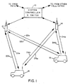
- FIG. 1 An exemplary terrestrial cellular mobile telephone system in which the present invention is embodied is illustrated in Figure 1.
- the system illustrated in Figure 1 utilizes CDMA modulation techniques in communications between the system mobile user, and the cell-sites.
- Cellular systems in large cities may have hundreds of cell-site stations serving hundreds of thousands of mobile telephones.
- the use of CDMA techniques readily facilitates increases in user capacity in systems of this size as compared to conventional FM modulation cellular systems.
- system controller and switch 10 typically includes appropriate interface and processing hardware for providing system control information to the cell-sites.
- Controller 10 controls the routing of telephone calls from the public switched telephone network (PSTN) to the appropriate cell-site for transmission to the appropriate mobile unit.
- Controller 10 also controls the routing of calls from the mobile units via at least one cell-site to the PSTN. Controller 10 may direct calls between mobile users via the appropriate cell-site stations since such mobile units do not typically communicate directly with one another.
- PSTN public switched telephone network
- Controller 10 may be coupled to the cell-sites by various means such as dedicated telephone lines; optical fiber links or by radio frequency communications.
- FIG 1 two exemplary cell-sites, 12 and 14, along with two exemplary mobile units 16 and 18 which include cellular telephones are illustrated.
- Arrows 20a-20b and 22a-22b respectively define the possible communication links between cell-site 12 and mobile units 16 and 18.
- arrows 24a-24b and arrows 26a-26b respectively define the possible communication links between cell-site 14 and mobile units 18 and 16.
- Cell-sites 12 and 14 normally transmit using equal power.
- Cell-sites 12 and 14 are in the typical case are terrestrial base stations which define cell service areas, however it should be understood that earth orbit relay satellites, such as satellites 13 and 15, may be used to provide more complete cellular coverage, particularly for remote areas.
- earth orbit relay satellites such as satellites 13 and 15
- signals are relayed between the mobile users and the terrestrial base stations using satellites 13 and 15.
- the satellite case also provides the ability for communication between a mobile unit and one or more base stations via multiple transponders on the same satellite or through different satellites.
- Mobile unit 16 measures the total received power in pilot signals transmitted by cell-sites 12 and 14 upon path 20a and 26a.
- mobile unit 18 measures the total received power in pilot signal as transmitted by cell-sites 12 and 14 upon paths 22a and 24a.
- pilot signal power is measured in the receiver where the signal is a wideband signal. Accordingly, this power measurement is made prior to correlation of the received signal with a pseudonoise (PN) spectrum spreading signal.
- PN pseudonoise
- the received signal power When mobile unit 16 is closer to cell-site 12, the received signal power will be dominated by the signal traveling path 20a. When mobile unit 16 is nearer to cell-site 14, the received power will be dominated by the signal traveling on path 26a. Similarly, when mobile unit 18 is closer to cell-site 14, the received power will be dominated by the signal on path 24a. When mobile unit 18 is closer to cell-site 12, the received power will be dominated by the signal traveling on path 22a.
- Each of mobile units 16 and 18 uses the resultant measurement, together with knowledge of the cell-site transmitter power and the mobile unit antenna gain to estimate the path loss to the closest cell-site.
- the estimated path loss, together with knowledge of the mobile antenna gain and the cell-site G/T is used to determine the nominal transmitter power required to obtain the desired carrier-to-noise ratio in the cell-site receiver.
- the knowledge by the mobile units of the cell-site parameters may be either fixed in memory or transmitted in cell-site information broadcast signals, setup channel, to indicate other than nominal conditions for a particular cell-site.
- the mobile unit transmitted signals will arrive at the nearest cell-site precisely at the desired carrier-to-noise ratio.
- the desired performance will be obtained with the minimum amount of mobile unit transmitter power.
- the minimization of the mobile unit transmitted power is important in a CDMA system because each mobile unit causes interference to every other mobile unit in the system. In minimizing the mobile unit transmitter power, system interference will be held to a minimum, thus allowing additional mobile users to share the frequency band. Accordingly, system capacity and spectral efficiency is maximized.
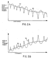
- Figure 2A illustrates the effect of both Rayleigh fading as a function of distance on the strength of the cell-site transmitted signal as received at a mobile unit.
- the average path loss, indicated by curve 30, is determined primarily by the fourth-power of the distance between the cell-site and the mobile unit, and by the shape of the terrain between them. As distance increases between the mobile unit and the cell-site, signal power decreases as received at the mobile unit for a constant power transmitted cell-site signal.
- the average path loss is the same for both directions of the link, and typically exhibits a log-normal distribution about the average path loss.
- Curve 32 represents the variation in signal path loss as a result of Rayleigh fading.
- the Rayleigh fading is typically independent for the two directions of the cell-site/mobile unit communication link, i.e. outbound and inbound channels. For example, when the outbound channel is fading, the inbound channel is not necessarily fading at the same time.
- Figure 2B illustrates the mobile unit transmitter power adjusted to correspond to the link path signal strength of Figure 2A.
- curve 34 represents the desired average transmit power corresponding to the average path loss of curve 30 of Figure 2A.
- curve 36 corresponds to the mobile unit transmitter power responding to the Rayleigh fading as represented by curve 32 of Figure 2A.
- the present invention envisions the use of an optional nonlinear filter to control rapid upward excursions, or increases, in transmitter power.
- the present invention also utilizes closed loop power adjustment feedback from the cell-site to adjust mobile unit transmitter power.
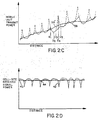
- Figure 2C illustrates the mobile unit transmitter power corresponding to Figure 2A without taking into consideration the cell-site closed loop power adjustment feedback.
- the desired average transmit power as represented by curve 34', corresponds to the mobile unit received signal strength of curve 30 of Figure 2A.
- Curve 38 illustrates the transmitter power utilizing the optional non-linear filter in power control of the present invention.
- transmitter power decreases rather quickly corresponding to a sudden improvement in the channel.
- the channel degrades with a corresponding increase in transmitter power. The change in degradation is not so significant such that the non-linear filter maximum rate limits the rate of increase in transmitter power.
- the channel degrades much more rapidly than the nonlinear filter will permit an increase in transmitter power. During this period, transmitter power increases at the maximum rate permitted by the non-linear filter. During the distance change indicated by marks D 4 -D 5 , the channel begins improving. However, as the quality of the channel improves the transmitter power continues to increase at the maximum rate until transmitter power is sufficient to meet the desired level such as at mark D 5 .
- Figure 2D is a graph illustrating the cell-site received signal power strength with respect to transmissions of the mobile unit as it travels from the cell-site.
- Curve 40 indicates the desired average received signal power at the cell-site for a signal transmitted from a mobile unit. It is desirable that the average received signal power be at a constant level, yet a minimum necessary to assure a quality communication link with the mobile unit. Corrections are made at the mobile unit to correct for Rayleigh fading in the cell-site transmitted signal.
- the mobile unit transmitted signal experiences Rayleigh fading before arriving at the cell-site receiver.
- the signal received at the cell-site is therefore a signal of constant average received power level but still with the Rayleigh fading of the inbound channel impressed thereupon.
- Curve 42 represents the Rayleigh fading that occurs on the inbound signal.
- a high speed power control process is utilized in the present invention to compensate for the Rayleigh fading.
- the speed at which the open loop control operates is slowed down.
- curve 44 illustrates the mobile unit transmitted signal power as received at the cell-site when compensating for average path loss and Rayleigh fading on both the inbound and outbound channels. As can be seen in Figure 2D curve 44 follows close to curve 40 except for instances of severe fading where the fading process is minimized by the closed loop control.
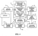
- antenna 52 is provided for receiving multiple mobile unit transmitted signals which are then provided to analog receiver 54 for amplification, frequency downconversion and IF processing of the received RF signal.
- the analog signals output from receiver 54 are provided to a plurality of receiver modules or channel units for, extraction of user directed information signals, generation of power adjustment commands, and modulation of user input information signals for transmission.
- One such module used in communications with a particular mobile unit, such as mobile unit N, is module 50N.
- the output of receiver 54 is provided to a plurality of these modules including module 50N.
- Module 50N comprises digital data receiver 56, user digital baseband circuit 58, received power measurement circuitry 60 and transmit modulator 62.
- Digital data receiver 56 receives the wideband spread spectrum signals for correlating and despreading the mobile unit N transmitted signal to a narrowband signal for transfer to an intended recipient communicating with mobile unit N.
- Digital data receiver 56 provides the narrowband digital signals to user digital baseband circuitry 58.
- Digital data receiver 56 also provides the narrowband signal to received power measurement circuitry 60.
- Received power measurement circuitry 60 measures the power level in the received signal from mobile unit N. Received power measurement circuitry 60 in response to the measured level of power generates a power adjustment command which is input to transmit modulator 62 for transmission to mobile unit N. As previously discussed, the data bits in the power adjustment command are used by mobile unit N in adjusting mobile unit transmitter power.
- an appropriate power adjustment command is generated. Should the received power measurement be less than the preset level, the power adjustment command data bits are generated and indicate that an increase in mobile unit transmitter power is necessary. Similarly, if the received measurement is greater than the preset level, the power adjustment command is generated such that the mobile unit transmitter power is reduced. The power adjustment command is utilized to maintain a nominal received power level at the cell-site.
- the signal output from digital data receiver 56 is provided to user digital baseband circuitry 58 where it is interfaced for coupling to the intended recipient via the system controller and switch.
- baseband circuitry 58 receives user information signals intended for mobile unit N and provides them to transmit modulator 62.
- Transmit modulator 62 spread spectrum modulates the user addressable information signals for transmission to mobile unit N. Transmit modulator 62 also receives the power adjustment command data bits from received power measurement circuitry 60. The power adjustment command data bits are also spread spectrum modulated by transmit modulator 62 for transmission to mobile unit N. Transmit modulator 62 provides the spread spectrum modulated signal via transmit power control circuitry 63 to summer 64 where combined with spread spectrum signals from other module transmit modulators also located at the cell-site.
- the combined spread spectrum signals are input to summer 66 where they are combined with a pilot signal provided by pilot signal generator 68. These combined signals are then provided to circuitry (not shown) for frequency upconversion from the IF frequency band to the RF frequency band and amplified. The RF signals are then provided to antenna 52 for transmission.
- transmit power control circuitry may be disposed between summer 66 and antenna 52. This circuitry, under control of the cell-site processor, is responsive to power adjustment command signals transmitted by the mobile unit which are demodulated at the cell-site receiver and provided to the cell-site control processor for coupling to the circuitry.
- the mobile unit such as mobile unit N, includes an antenna 70 for collecting cell site transmitted signals and radiating mobile unit generated CDMA signals.
- antenna 70 is comprised of two separate antennas, one for transmission and another for reception.
- Mobile unit N receives the pilot signal, setup channel signals and the mobile unit N addressed signals using antenna 70, analog receiver 72 and digital data receiver system 74.
- Receiver 72 amplifies and frequency downconverts the received RF CDMA signals to IF, and filters the IF signals.
- the IF signals are output to digital data receiver 74 for digital processing.
- Receiver 72 also includes circuitry for performing an analog measurement of the combined power of the received signals. This power measurement is used to generate a feedback signal that is provided to transmit power control circuitry 76 for controlling transmit power.
- Digital data receiver system 74 is comprised of multiple digital data receivers.
- One digital data receiver, receiver 74a is used to search for pilot signals that are transmitted by each cell-site. These pilot signals may be multipath signals of a same cell-site, pilot signals transmitted by different cell-sites, or a combination of both.
- the different cell-site transmitted pilot signals are each of a same spreading code but of at a different code phase offset for identification of the particular cell-site.
- Receiver 74a provides to control processor 78 signals indicative of the strongest pilot signals, whether they be multipath signals of a single cell-site or from different cell-sites. Control processor 78 uses the information provided from receiver 74a in establishing and maintaining communication with the cell-site or cell-site.
- Digital data receiver system 74 is further comprised of digital data receivers 74b and 74c. Although only two receivers are illustrated, additional receivers.may be provided.
- Receivers 74a and 74b are used for despreading and correlating the received signals addressed to mobile unit N from one cell-site or from multiple cell-sites for cell diversity mode communications.
- Receivers 74b and 74c are assigned to process different multipath signals from the same cell-site, or signals from different cell-sites when in a cell diversity mode. Under the control of control processor 78, receivers 74b and 74c process the assigned signal intended for the mobile user. Typically receivers 74b and 74c are assigned to process the spread spectrum digital user data signal which correspond to the strongest pilot signals identified by receiver 74a.
- Receivers 74b and 74c provides demodulated user data such as digitized encoded speech to diversity combiner and decoder circuitry 75.
- Circuitry 75 coherently combines the different signals from receivers 74b and 74, whether they be multipath signals or cell diversity signal so as to provide a single user data signal.
- Circuitry 75 also performs decoding and error correction on the user data.
- the signal output from circuitry is provided to digital baseband circuitry 82 for interface with the user.
- Baseband circuitry 82 includes interface hardware for coupling receiver 74 and transmit modulator 82 to the user handset (not shown).
- Receivers 74b and 74c also separate the digital user data from the power adjustment commands generated by the cell-site(s) and transmitted in the user data signals.
- the extracted power adjustment command data bits are sent to control processor 78.
- Processor 78 analyzes the power adjustment commands to so as to provide control over the mobile unit transmitter power.
- processor 78 is responsive to the power adjustment command data bits generates a transmit power control command that is provided to transmit power control circuitry 80.
- processor 78 provides a signal to transmit power control circuitry 76 to increase transmitter power.
- processor 78 provides a signal to transmit power control circuitry 76 to decrease transmitter power.
- additional factors must be taken into consideration by processor 78.
- the power adjustment commands are arriving from two different cell-sites.
- Mobile unit transmitter power as measured at these different sites may be different, and therefore care must be taken in controlling the mobile unit transmitter power to avoid transmitting at a level that would adversely affect communications between the cell-sites and other users. Since the cell-site power adjustment command generation process is independent from each other cell-site, the mobile unit must respond to the received commands in a manner that does not affect other users.
- control processor operates in a logical AND function and generates a power control signal to transmit power control circuitry 76 indicative of an increase in transmitter power.
- a request for a power increase request corresponds to a logical "1" while a power decrease request corresponds to a logical "0".
- Transmit power control circuitry 76 is responsive to this type of power control signal so as to increase the transmitter power. This situation may occur when the communication path to both cell-sites is degraded for one or more reasons.
- processor 78 again operates in the above mentioned logical AND function to generate a power control signal to transmit power control circuitry 76 indicative of an decrease in transmitter power. Transmit power control circuitry 76 is responsive to this type of power control signal so as to decrease the transmitter power. This situation may occur when the communication path to one cell-site is degraded while the communication path to the' other cell-site becomes improved.
- mobile unit transmitter power is increased only when all cell-sites in which the mobile unit is in communication with request an increase in power, and is decreased when any one or more of these cell-sites request a decrease in power.
- a mobile unit will not transmit at a power level that would unnecessarily increase the level of system interference for other users, but yet maintain a level that would facilitate communication with at least one cell-site.
- Processor 78 also provides a level set command to transmit power control circuitry 76 for use in setting transmitter power level in the with respect to the wideband power measurement from analog receiver 72. Further details on the interaction of receiver 72, transmit power control circuitry 76 and 80, and processor 78 are described in further detail with reference to Figure 5.
- Data to be transmitted is provided through baseband circuitry 82 where it is encoded and provided to transmit modulator 84.
- the data is spread spectrum modulated by transmit modulator 84 according to an assigned spreading code.
- the spread spectrum signals are output from transmit modulator 84 to transmit power control circuitry 80.
- the signal power is adjusted in accordance with the transmit power control command provided by control processor 78.
- This power adjusted signal is provided from transmit power control circuitry 80 to transmit power control circuitry 76 where the signal is adjusted in accordance with the analog measurement control signal.
- the power level could be adjusted by a single variable gain amplifier with two input control signals combined before being applied to the variable gain amplifier. However in the illustrated exemplary embodiment the two control functions are shown as separate elements.
- receiver 72 measures the combined power level of all signals received from all cell-sites. These power level measurement results are used in controlling the power level as set by transmit power control circuitry 76.
- Transmit power control circuitry 76 includes circuitry in which the rate of increase transmitter power is limited by an optional non-linear filter as previously discussed. The rate of increase is set to be no faster than the rate at which transmit power control circuitry 80 can turn the power down in response to a series of downward commands from the cell-site as processed by receiver 74 and processor 78.
- Figure 5 illustrates in further detail the power control aspect of mobile unit N discussed with reference to Figure 4.
- received RF signals from the antenna are provided to frequency downconverter 90 where the received RF signals are converted to an IF frequency.
- the IF frequency signals are coupled to bandpass filter 92 where out of band frequency components are removed from the signals.
- the filtered signals are output from filter 92 to variable gain IF amplifier 94 where the signals are amplified.
- the amplified signals are output from amplifier 94 to an analog to digital (A/D) converter (not shown) for digital signal processing operations on the signals.
- A/D analog to digital
- the output of amplifier 94 is also coupled to automatic gain control (AGC) detector circuit 96.
- AGC automatic gain control
- AGC detector circuit 96 generates a gain control signal which is coupled to a gain control input of amplifier 94. This gain control signal is used to control the gain of the amplifier 94 so as to maintain a constant average power level as output from amplifier 94 to the A/D converter.
- AGC detector circuit 96 also provides an output to one input of comparator 98.
- the other input of comparator 98 is provided with a level set signal from the mobile unit processor (not shown). This level set signal is indicative of a desired transmitter reference power level.
- These input signals are compared by comparator 98 with the comparison signal provided to an optional non-linear filter circuit 100. This comparison signal corresponds to a deviation in the received power measurement from a desired mobile unit transmitter power level.
- Filter 100 may be configured as a simple resistor-diode-capacitor circuit.
- the input to the circuit is a common node shared by two resistors.
- the other end of each resistor is coupled to a respective diode.
- the diodes are reversed in their connection to the resistors and the other end of each diode coupled together at a common node as an output of the filter.
- a capacitor is coupled between the diode common node and ground.
- the filter circuit is designed to limit the rate of power increase to less than 1 dB per millisecond.
- the rate of power decrease is typically set to be about ten times faster than the rate of power increase, i.e. 10 dB per millisecond.
- the output of filter 100 is provided as a power level control signal input to the gain control input of variable gain IF amplifier 102.
- AGC detector circuit 96, comparator 98 and filter 100 estimate received mobile unit signal power and the power correction necessary for the mobile unit transmitter. This correction is used to maintain a desired transmitter power level in conditions of fading on the outbound channel that are common to the inbound channel.
- Transmit modulator circuit 84 of Figure 4 provides a low power, IF frequency spread spectrum signal to an input of variable gain IF amplifier 104.
- Amplifier 104 is gain controlled by a power level control signal from processor 78 ( Figure 4). This power level control signal is derived from the closed loop power adjustment command signal transmitted by the cell-site and processed by the mobile unit as discussed with reference to Figure 4.
- the power adjustment command signal consists of a sequence of power-up and power-down commands that are accumulated in the mobile unit processor.
- the mobile unit control processor starts with the gain control level set to a nominal value.
- Each power-up command increases the value of a gain control command corresponding to a resultant approximate 1 dB increase in amplifier gain.
- Each power-down command decreases the value of the gain control command, corresponding to a resultant approximate 1 dB decrease in amplifier gain.
- the gain control command is converted to analog form by a digital to analog (D/A) converter (not shown) before applied to amplifier 104 as the power level control signal.
- D/A digital to analog
- the mobile unit reference power level may be stored in the memory of the control processor. In the alternative, the mobile unit reference power level may be contained within a signal sent to the mobile unit. This signal command data is separated by the digital data receiver and interpreted by the control processor in setting the level. This signal as provided from the control processor is converted by a digital to analog (D/A) converter (not shown) before input to comparator 98.
- D/A digital to analog
- amplifier 104 The output of amplifier 104 is provided as an input to amplifier 102.
- Amplifier 102 as previously mentioned is also a variable gain IF amplifier with the gain determined according to the power level control signal output from filter 100.
- the signal for transmission is thus amplified in accordance with the gain set by the power level control signal.
- the amplified signal output from amplifier 102 and is further amplified and frequency translated to the RF frequency for transmission.
- the RF signal is then fed to the antenna for transmission.
- Figure 6 illustrates in further detail the power control scheme of the cell-site as illustrated in Figure 3.
- a mobile unit transmitted signal is received at the cell-site.
- the received signal is processed by the cell-site analog receiver and cell-site corresponding to mobile unit N.
- the received analog signal is converted from analog to digital form by A/D converter 110.
- the digital signal output from A/D converter is provided to pseudorandom noise (PN) correlator 112 where the signal undergoes a correlation process with a PN signal provided from PN generator 114.
- PN correlator 112 is provided to a fast Hadamard transform digital filter 114 where the signal is filtered.
- the output of filter 114 is provided to a user data decoder circuit 116 which provides user data to the user digital baseband circuitry. Decoder 116 provides the largest transform filter symbols to power averager circuit 118. Power averager circuit 118 averages the largest transform outputs over a one millisecond interval using well known digital techniques.
- a signal indicative of each average power level is output from power averager 118 to comparator 120.
- Comparator 120 also receives a power level set signal indicative of the desired received power level. This desired received power level is set by the control processor for the cell-site. Comparator 120 compares the two input signals and provides an output signal indicative of the deviation of the average power level from the desired power level. This signal is provided output to power up/down command generator 122. Generator 122 in response to the comparison generates either a power-up or a power-down command. Power command generator 122 provides the power control commands to the cell-site transmit modulator for transmission and control of the transmitter power of mobile unit N.
- a power-down command is generated and transmitted to mobile unit N.
- a power-up command is generated and transmitted.
- the up/down commands are transmitted at a high rate, nominally 800 commands per second in the exemplary embodiment. At one bit per command, the overhead of the power command is insignificant compared to the bit rate of a high quality digital voice signal.
- the power adjustment command feedback compensates for changes in the inbound channel that are independent of the outbound channel. These independent inbound channel changes are not measured in the outbound channel signal. Therefore the path loss estimate based upon then outbound channel and the corresponding transmitter power adjustment do not reflect the changes in the inbound channel. Thus, the power adjustment command feedback is used to compensate for adjustments in the mobile unit transmitter power based on the inbound channel path losses that do not exist in the outbound channel.
- the present invention provides a novel and unique power control circuitry at the cell-site for minimizing delay and latency of measurement and transmission.
- the power control circuitry at the mobile unit, analog control and digital command response, provides a vastly improved power control process in the cellular mobile telephone system.
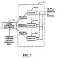
- FIG 7 illustrates the typical cell-site configuration in which multiple modules 50A - 50Z are included. Modules 50A - 50Z are each identical in construction with that of module 50N of Figure 3. In Figure 7, mobile unit N is considered to be in communication with module 50N for purposes of illustration.
- Each of modules 50A - 50Z are coupled to system controller 10 as was discussed with reference to Figure 1. Through the link to system controller 10, each module 50A - 50Z demodulates and relays the mobile unit power requests to system controller 10.
- System controller 10 in response to a mobile unit request for an increase in module transmitter power may reduce all transmitter power for some or all other module transmitters by a small increment.
- System controller 10 would transmit a power control command to a cell-site, typically to the cell-site control processor.
- the cell-site control processor in response thereto reduces transmitter power of the cell-site other modules.
- the reduction in power of the other modules makes available an increase in power to the module servicing the requesting mobile user by n times the increment, where n is the number of modules reducing transmitter power.
- n is the number of modules reducing transmitter power.
- module 50N transmits at a nominal power level as discussed above.
- the power level is set by a command from the cell-site control processor, with this command modified at the cell-site control processor by a command from the system controller.
- the command input to transmit power control circuitry 63 is used typically to decrease transmitter power.
- Transmit power control circuitry 63 may be configured as a variable gain amplifier as was discussed with reference to Figure 5.
- the quality of the received data signal is measured in the form of data frame errors. From this measurment the level of adequacy of the signal power is determined, where execessive frame errors are an indication insufficient signal power.
- Frame error information may be generated from the known error correction circuitry such as through the normalization rate of a Viterbi decoder or Cyclic Redundancy Check/Code (CRC), or a combination thereof.
- Various other techniques that are well known in the art may be used for indirectly or directly measuring signal power. Other techniques include re-encoding the data and comparing with the originally transmitted data for an indication of errors. It should further be understood that the power of the data signal itself may be measured and used as an indication of link quality.
- the frame error information is provided to processor 78.
- Processor 78 in response to a frame error rate exceeding a predetermined threshold level over a certain number of frames, such as 5 frames, generates a power increase request message that is output to transmit modulator 84. Transmit modulator 84 modulates the power request message for transmission to the cell-site.
- system controller through the cell-site modules may solicit a power level measurement at the mobile units.
- Each mobile unit communicates its power level measurement to the system controller.
- the system controller may adjust transmission power for the various cell-site modules for system optimization.
Abstract

Description
Claims (15)
- A mobile station comprising:an antenna for receiving a first spread spectrum signal;a despreader for despreading the first spread spectrum signal;a demultiplexer for demultiplexing the first spread spectrum signal to recover power commands;a step size algorithm device having an algorithm for adjusting a gain of a variable gain device; anda variable gain device for adjusting the gain of a second spread spectrum signal to be transmitted from the mobile station in response to the algorithm and recovered power commands.
- The mobile station of claim 1 wherein the step size algorithm device varying a step size of increases or decreases in the gain of the variable gain device.
- The mobile station of claim 1 or 2 further comprising an accumulator for use in analyzing multiple power commands.
- The mobile station of claim 3 wherein the multiple power commands are a sequence of power commands.
- The mobile station of claim 4 wherein the algorithm adjusts the gain by a first amount if each power command in the sequence of power commands has a same value and a second amount if each power command in the sequence of power commands has differing values.
- A mobile station comprising:means for receiving a first spread spectrum signal;means for despreading the first spread spectrum signal;means for demultiplexing the first spread spectrum signal to recover power commands;step size algorithm means having an algorithm for adjusting a gain; andmeans for adjusting the gain of a second spread spectrum signal to be transmitted from the mobile station in response to the algorithm and recovered power commands.
- The mobile station of claim 6 wherein the step size algorithm means varying a step size of increases or decreases in the gain of the variable gain device.
- The mobile station of claim 6 or 7 further comprising means for use in analyzing multiple power commands.
- The mobile station of claim 8 wherein the multiple power commands are a sequence of power commands.
- The mobile station of claim 9 wherein the algorithm adjusts the gain by a first amount if each power command in the sequence of power commands has a same value and a second amount if each power command in the sequence of power commands has differing values.
- A method comprising:receiving a first spread spectrum signal by a mobile station;despreading the first spread spectrum signal;demultiplexing the first spread spectrum signal to recover power commands; providing an algorithm for adjusting a gain value; andmeans for adjusting a gain of a second spread spectrum signal to be transmitted from the mobile station in response to the algorithm and recovered power commands.
- The method of claim 11 further comprising varying a step size of increases or decreases in the gain of the variable gain device.
- The method of claim 11 or 12 further comprising providing an accumulator for use in analyzing multiple power commands.
- The method of claim 13 wherein the multiple power commands are a sequence of power commands.
- The method of claim 14 wherein the algorithm adjusts the gain by a first amount if each power command in the sequence of power commands has a same value and a second amount if each power command in the sequence of power commands has differing values.
Priority Applications (1)
| Application Number | Priority Date | Filing Date | Title |
|---|---|---|---|
| EP10182945.5A EP2264911B1 (en) | 1995-01-04 | 1995-12-22 | Spread-spectrum system and method |
Applications Claiming Priority (4)
| Application Number | Priority Date | Filing Date | Title |
|---|---|---|---|
| US368710 | 1995-01-04 | ||
| US08/368,710 US5574747A (en) | 1995-01-04 | 1995-01-04 | Spread spectrum adaptive power control system and method |
| EP00114941A EP1043844B1 (en) | 1995-01-04 | 1995-12-22 | Communication station, method and network for power control in spread spectrum systems |
| EP95943981A EP0801856B1 (en) | 1995-01-04 | 1995-12-22 | Spread-spectrum system and method for adaptive power control in a cellular communication network |
Related Parent Applications (2)
| Application Number | Title | Priority Date | Filing Date |
|---|---|---|---|
| EP95943981.1 Division | 1996-07-11 | ||
| EP00114941.8 Division | 2000-07-18 |
Related Child Applications (1)
| Application Number | Title | Priority Date | Filing Date |
|---|---|---|---|
| EP10182945.5A Division EP2264911B1 (en) | 1995-01-04 | 1995-12-22 | Spread-spectrum system and method |
Publications (1)
| Publication Number | Publication Date |
|---|---|
| EP1569360A1 true EP1569360A1 (en) | 2005-08-31 |
Family
ID=23452422
Family Applications (6)
| Application Number | Title | Priority Date | Filing Date |
|---|---|---|---|
| EP10182945.5A Expired - Lifetime EP2264911B1 (en) | 1995-01-04 | 1995-12-22 | Spread-spectrum system and method |
| EP00114940A Expired - Lifetime EP1041728B1 (en) | 1995-01-04 | 1995-12-22 | Spread-spectrum system and method |
| EP05010690A Withdrawn EP1569360A1 (en) | 1995-01-04 | 1995-12-22 | Spread-spectrum system and method |
| EP00114941A Expired - Lifetime EP1043844B1 (en) | 1995-01-04 | 1995-12-22 | Communication station, method and network for power control in spread spectrum systems |
| EP00114939A Expired - Lifetime EP1041727B1 (en) | 1995-01-04 | 1995-12-22 | Spread-spectrum apparatus and method |
| EP95943981A Expired - Lifetime EP0801856B1 (en) | 1995-01-04 | 1995-12-22 | Spread-spectrum system and method for adaptive power control in a cellular communication network |
Family Applications Before (2)
| Application Number | Title | Priority Date | Filing Date |
|---|---|---|---|
| EP10182945.5A Expired - Lifetime EP2264911B1 (en) | 1995-01-04 | 1995-12-22 | Spread-spectrum system and method |
| EP00114940A Expired - Lifetime EP1041728B1 (en) | 1995-01-04 | 1995-12-22 | Spread-spectrum system and method |
Family Applications After (3)
| Application Number | Title | Priority Date | Filing Date |
|---|---|---|---|
| EP00114941A Expired - Lifetime EP1043844B1 (en) | 1995-01-04 | 1995-12-22 | Communication station, method and network for power control in spread spectrum systems |
| EP00114939A Expired - Lifetime EP1041727B1 (en) | 1995-01-04 | 1995-12-22 | Spread-spectrum apparatus and method |
| EP95943981A Expired - Lifetime EP0801856B1 (en) | 1995-01-04 | 1995-12-22 | Spread-spectrum system and method for adaptive power control in a cellular communication network |
Country Status (16)
| Country | Link |
|---|---|
| US (16) | US5574747A (en) |
| EP (6) | EP2264911B1 (en) |
| JP (9) | JP3736807B2 (en) |
| AT (4) | ATE293307T1 (en) |
| AU (1) | AU4529796A (en) |
| DE (7) | DE69534149T2 (en) |
| DK (3) | DK1041727T3 (en) |
| ES (4) | ES2154247T3 (en) |
| FI (4) | FI116256B (en) |
| HK (3) | HK1031954A1 (en) |
| IL (6) | IL116444A (en) |
| MY (6) | MY123400A (en) |
| PT (1) | PT801856E (en) |
| TW (1) | TW281837B (en) |
| WO (1) | WO1996021295A1 (en) |
| ZA (1) | ZA9510969B (en) |
Cited By (1)
| Publication number | Priority date | Publication date | Assignee | Title |
|---|---|---|---|---|
| CN102361463A (en) * | 2011-05-27 | 2012-02-22 | 福建三元达通讯股份有限公司 | Radio frequency (RF) band selector |
Families Citing this family (177)
| Publication number | Priority date | Publication date | Assignee | Title |
|---|---|---|---|---|
| US6873643B2 (en) * | 1990-11-16 | 2005-03-29 | Interdigital Technology Corporation | Spread spectrum adaptive power control communications system and method |
| US5870393A (en) * | 1995-01-20 | 1999-02-09 | Hitachi, Ltd. | Spread spectrum communication system and transmission power control method therefor |
| JP3192047B2 (en) * | 1994-06-03 | 2001-07-23 | キヤノン株式会社 | Spread spectrum receiver |
| US5574747A (en) * | 1995-01-04 | 1996-11-12 | Interdigital Technology Corporation | Spread spectrum adaptive power control system and method |
| TW347616B (en) * | 1995-03-31 | 1998-12-11 | Qualcomm Inc | Method and apparatus for performing fast power control in a mobile communication system a method and apparatus for controlling transmission power in a mobile communication system is disclosed. |
| US6977967B1 (en) * | 1995-03-31 | 2005-12-20 | Qualcomm Incorporated | Method and apparatus for performing fast power control in a mobile communication system |
| US5764687A (en) * | 1995-06-20 | 1998-06-09 | Qualcomm Incorporated | Mobile demodulator architecture for a spread spectrum multiple access communication system |
| US7020111B2 (en) | 1996-06-27 | 2006-03-28 | Interdigital Technology Corporation | System for using rapid acquisition spreading codes for spread-spectrum communications |
| US7929498B2 (en) * | 1995-06-30 | 2011-04-19 | Interdigital Technology Corporation | Adaptive forward power control and adaptive reverse power control for spread-spectrum communications |
| US6885652B1 (en) | 1995-06-30 | 2005-04-26 | Interdigital Technology Corporation | Code division multiple access (CDMA) communication system |
| US6816473B2 (en) | 1995-06-30 | 2004-11-09 | Interdigital Technology Corporation | Method for adaptive forward power control for spread-spectrum communications |
| US6831905B1 (en) | 1995-06-30 | 2004-12-14 | Interdigital Technology Corporation | Spread spectrum system assigning information signals to message-code signals |
| US6697350B2 (en) | 1995-06-30 | 2004-02-24 | Interdigital Technology Corporation | Adaptive vector correlator for spread-spectrum communications |
| US6788662B2 (en) | 1995-06-30 | 2004-09-07 | Interdigital Technology Corporation | Method for adaptive reverse power control for spread-spectrum communications |
| ZA965340B (en) | 1995-06-30 | 1997-01-27 | Interdigital Tech Corp | Code division multiple access (cdma) communication system |
| JP3269959B2 (en) * | 1996-01-16 | 2002-04-02 | 株式会社日立国際電気 | Correlation filter and CDMA receiver |
| US5722051A (en) * | 1996-02-13 | 1998-02-24 | Lucent Technologies Inc. | Adaptive power control and coding scheme for mobile radio systems |
| US6697415B1 (en) * | 1996-06-03 | 2004-02-24 | Broadcom Corporation | Spread spectrum transceiver module utilizing multiple mode transmission |
| JPH09327072A (en) * | 1996-06-05 | 1997-12-16 | Hitachi Ltd | Cdma communication method and spread spectrum communication system |
| JPH1079701A (en) | 1996-09-03 | 1998-03-24 | Fujitsu Ltd | Mobile communication terminal and its transmission power control system |
| US5825826A (en) * | 1996-09-30 | 1998-10-20 | Motorola, Inc. | Method and apparatus for frequency domain ripple compensation for a communications transmitter |
| US6259724B1 (en) * | 1996-10-18 | 2001-07-10 | Telefonaktiebolaget L M Ericsson (Publ) | Random access in a mobile telecommunications system |
| JP2760352B1 (en) * | 1996-11-29 | 1998-05-28 | 日本電気株式会社 | Cell search circuit for CDMA |
| JPH10173594A (en) * | 1996-12-06 | 1998-06-26 | Hitachi Ltd | Code division multiple access communication system and sending power control method |
| JP2800891B2 (en) * | 1996-12-17 | 1998-09-21 | 日本電気株式会社 | CDMA multi-code transmission device |
| JP3795984B2 (en) * | 1996-12-20 | 2006-07-12 | 富士通株式会社 | Wireless receiver |
| US5956369A (en) * | 1997-02-24 | 1999-09-21 | Golden Bridge Technology, Inc. | Spread spectrum multipath combining subsystem and method |
| US6148313A (en) * | 1997-04-09 | 2000-11-14 | Ge Capital Spacenet Services, Inc. | Correlator method and apparatus |
| US6396867B1 (en) * | 1997-04-25 | 2002-05-28 | Qualcomm Incorporated | Method and apparatus for forward link power control |
| US5896411A (en) * | 1997-05-05 | 1999-04-20 | Northern Telecom Limited | Enhanced reverse link power control in a wireless communication system |
| US5953365A (en) * | 1997-05-08 | 1999-09-14 | Sicom, Inc. | Interference-tolerant spread-spectrum receiver and method therefor |
| US6185431B1 (en) * | 1997-06-18 | 2001-02-06 | Oki Telecom, Inc. | Mobile station closed loop output power stability system for weak signal conditions |
| JP3380446B2 (en) * | 1997-10-20 | 2003-02-24 | 株式会社鷹山 | Receiver for CDMA communication system |
| US6700939B1 (en) * | 1997-12-12 | 2004-03-02 | Xtremespectrum, Inc. | Ultra wide bandwidth spread-spectrum communications system |
| US6175745B1 (en) * | 1997-12-24 | 2001-01-16 | Telefonaktiebolaget Lm Ericsson | Initial transmit power determination in a radiocommunication system |
| EP0930721B1 (en) * | 1997-12-29 | 2007-06-20 | Nortel Matra Cellular | Telecommunications system with bandwidth agile receivers and transmitters |
| US6408019B1 (en) | 1997-12-29 | 2002-06-18 | Georgia Tech Research Corporation | System and method for communication using noise |
| WO1999035769A1 (en) * | 1997-12-31 | 1999-07-15 | Schleifring Und Apparatebau Gmbh | Device for transmitting signals with low-interference |
| US20040160906A1 (en) | 2002-06-21 | 2004-08-19 | Aware, Inc. | Multicarrier transmission system with low power sleep mode and rapid-on capability |
| US6084919A (en) * | 1998-01-30 | 2000-07-04 | Motorola, Inc. | Communication unit having spectral adaptability |
| US6212399B1 (en) * | 1998-03-06 | 2001-04-03 | Lucent Technologies, Inc. | Method and apparatus for controlling the power radiated by a wireless terminal in a telecommunications system based on a variable step size |
| US6085104A (en) * | 1998-03-25 | 2000-07-04 | Sharp Laboratories Of America, Inc. | Pilot aided, time-varying finite impulse response, adaptive channel matching receiving system and method |
| CN101013910B (en) * | 1998-03-26 | 2011-09-07 | 三菱电机株式会社 | Spread spectrum communication apparatus and method |
| FI105131B (en) * | 1998-03-27 | 2000-06-15 | Nokia Networks Oy | Method for performing power control of a physical channel in a radio system |
| JP3728116B2 (en) | 1998-06-02 | 2005-12-21 | キヤノン株式会社 | Communication method and apparatus |
| US6304591B1 (en) | 1998-07-10 | 2001-10-16 | Aloha Networks, Inc. | Match filter architecture based upon parallel I/O |
| US6658202B1 (en) | 1998-09-09 | 2003-12-02 | Smartdisk | Portable data transfer and mass storage device for removable memory modules |
| US6987927B1 (en) | 1998-09-09 | 2006-01-17 | Smartdisk Corporation | Enhanced digital data collector for removable memory modules |
| US6370183B1 (en) * | 1998-10-26 | 2002-04-09 | Nortel Networks Limited | Predictive rake receiver for CDMA mobile radio systems |
| US6411610B1 (en) * | 1998-11-05 | 2002-06-25 | Nortel Networks Limited | Correlation for synchronizing to long number sequences in communications systems |
| US6512925B1 (en) * | 1998-12-03 | 2003-01-28 | Qualcomm, Incorporated | Method and apparatus for controlling transmission power while in soft handoff |
| US6138034A (en) * | 1998-12-04 | 2000-10-24 | Motorola, Inc. | Method for transmitting a quick paging channel at different power levels |
| US7346120B2 (en) | 1998-12-11 | 2008-03-18 | Freescale Semiconductor Inc. | Method and system for performing distance measuring and direction finding using ultrawide bandwidth transmissions |
| US6269239B1 (en) * | 1998-12-11 | 2001-07-31 | Nortel Networks Corporation | System and method to combine power control commands during soft handoff in DS/CDMA cellular systems |
| EP1011281A3 (en) * | 1998-12-18 | 2000-07-05 | TELEFONAKTIEBOLAGET L M ERICSSON (publ) | Flexible CDMA combiner |
| FR2788177B1 (en) * | 1998-12-30 | 2001-02-09 | Mitsubishi Electric Inf Tech | METHOD FOR CONTROLLING THE POWER RECEIVED FROM A TRANSMITTER BY A RECEIVER OF A TELECOMMUNICATIONS SYSTEM, POWER CONTROL SYSTEM AND TRANSMITTER OF A TELECOMMUNICATIONS SYSTEM PROVIDED FOR CARRYING OUT SUCH A METHOD |
| JP2003525534A (en) * | 1998-12-30 | 2003-08-26 | フューチャーウェイブ インク. | Constant envelope modulation communication system |
| FI982856A (en) * | 1998-12-31 | 2000-07-01 | Nokia Networks Oy | Reception procedure and recipients |
| US6424642B1 (en) * | 1998-12-31 | 2002-07-23 | Texas Instruments Incorporated | Estimation of doppler frequency through autocorrelation of pilot symbols |
| JP2000201101A (en) * | 1999-01-07 | 2000-07-18 | Fujitsu Ltd | Spread spectrum communication system and its mobile unit |
| JP3618055B2 (en) * | 1999-02-05 | 2005-02-09 | 富士通株式会社 | Portable mobile terminal and transmitter |
| US6463296B1 (en) * | 1999-02-16 | 2002-10-08 | Telefonaktiebolaget L M Ericsson (Publ) | Power control in a CDMA mobile communications system |
| FI990354A (en) | 1999-02-18 | 2000-08-19 | Nokia Networks Oy | A method for automatic volume control of cellular radio network supports |
| JP3173600B2 (en) * | 1999-02-19 | 2001-06-04 | 日本電気株式会社 | Receiving machine |
| FR2791495B1 (en) * | 1999-03-26 | 2001-05-04 | France Telecom | METHOD FOR SYNCHRONIZING THE RHYTHM OF A DIGITAL SIGNAL |
| EP1045529B1 (en) * | 1999-04-12 | 2006-11-29 | Alcatel | A method for improving performances of a mobile radiocommunication system using a power control algorithm |
| EP1045528B1 (en) * | 1999-04-12 | 2004-02-18 | Alcatel | A method for improving performances of a mobile radiocommunication system using a power control algorithm |
| EP1045530B1 (en) * | 1999-04-12 | 2002-03-06 | Alcatel | Improved channel adaptive fast power control in CDMA |
| GB9908518D0 (en) * | 1999-04-14 | 1999-06-09 | Nokia Telecommunications Oy | Method for controlling transmission power |
| US6351246B1 (en) | 1999-05-03 | 2002-02-26 | Xtremespectrum, Inc. | Planar ultra wide band antenna with integrated electronics |
| CN1183695C (en) * | 1999-05-26 | 2005-01-05 | 皇家菲利浦电子有限公司 | Closed loop power control in radio communication system |
| DE19927203A1 (en) * | 1999-06-15 | 2000-12-28 | Alcatel Sa | Method for influencing the transmission of information signals in an interactive communication network |
| US6714585B1 (en) | 1999-06-25 | 2004-03-30 | Ericsson Inc. | Rake combining methods and apparatus using weighting factors derived from knowledge of spreading spectrum signal characteristics |
| US6801565B1 (en) | 1999-06-25 | 2004-10-05 | Ericsson Inc. | Multi-stage rake combining methods and apparatus |
| GB9919595D0 (en) | 1999-08-18 | 1999-10-20 | Nokia Telecommunications Oy | Connection control in a communication system |
| US6434135B1 (en) * | 1999-08-31 | 2002-08-13 | Interdigital Technology Corporation | Adaptive RF amplifier prelimiter |
| US7110434B2 (en) * | 1999-08-31 | 2006-09-19 | Broadcom Corporation | Cancellation of interference in a communication system with application to S-CDMA |
| FI19991871A (en) * | 1999-09-02 | 2001-03-02 | Nokia Networks Oy | Method for processing signal components in a communication system and a receiver |
| US6278726B1 (en) | 1999-09-10 | 2001-08-21 | Interdigital Technology Corporation | Interference cancellation in a spread spectrum communication system |
| SE9903235L (en) * | 1999-09-10 | 2001-03-11 | Ericsson Telefon Ab L M | Method and apparatus of a telecommunication system |
| US6115406A (en) | 1999-09-10 | 2000-09-05 | Interdigital Technology Corporation | Transmission using an antenna array in a CDMA communication system |
| SE516225C2 (en) * | 1999-09-17 | 2001-12-03 | Ericsson Telefon Ab L M | A method for power control and a radio system |
| US6961369B1 (en) | 1999-11-09 | 2005-11-01 | Aware, Inc. | System and method for scrambling the phase of the carriers in a multicarrier communications system |
| CN1124728C (en) * | 1999-11-25 | 2003-10-15 | 华为技术有限公司 | Multiple choise coherent detection method |
| EP2293459A3 (en) | 2000-01-07 | 2014-04-16 | TQ Delta, LLC | Systems and methods for characterizing transmission lines in a multi-carrier DSL environment |
| JP3991543B2 (en) | 2000-01-11 | 2007-10-17 | 株式会社日立製作所 | Imaging device |
| AU2001231248A1 (en) * | 2000-01-28 | 2001-08-07 | Morphics Technology, Inc. | Apparatus and method for sub-chip offset correlation in spread-spectrum communication systems |
| US6597723B1 (en) * | 2000-03-21 | 2003-07-22 | Interdigital Technology Corporation | Weighted open loop power control in a time division duplex communication system |
| US6600772B1 (en) * | 2000-03-21 | 2003-07-29 | Interdigital Communications Corporation | Combined closed loop/open loop power control in a time division duplex communication system |
| US6603797B1 (en) | 2000-03-22 | 2003-08-05 | Interdigital Technology Corporation | Outer loop/weighted open loop power control in a time division duplex communication system |
| EP1146657A1 (en) * | 2000-04-11 | 2001-10-17 | Siemens Aktiengesellschaft | Mobile station and method for allocating rake fingers |
| EP1154584A1 (en) * | 2000-05-12 | 2001-11-14 | Siemens Aktiengesellschaft | Mobile station and method for allocating rake fingers and tracking devices |
| US6289039B1 (en) * | 2000-06-14 | 2001-09-11 | Linex Technologies, Inc. | Spread-spectrum communications utilizing variable throughput reduction |
| KR100452860B1 (en) * | 2000-06-20 | 2004-10-14 | 삼성전자주식회사 | Method and apparatus for adjusting filter tap length of adaptive equalizer by using training sequence |
| US6862457B1 (en) * | 2000-06-21 | 2005-03-01 | Qualcomm Incorporated | Method and apparatus for adaptive reverse link power control using mobility profiles |
| US8301137B1 (en) | 2000-07-31 | 2012-10-30 | Interdigital Patent Corporation | Method and apparatus for wireless router multicast |
| US6700929B1 (en) | 2000-07-31 | 2004-03-02 | Rf Micro Devices, Inc. | Method and apparatus for multipath parameter estimation in spread-spectrum communications systems |
| US6647077B1 (en) | 2000-07-31 | 2003-11-11 | Rf Micro Devices, Inc. | Multipath parameter estimation in spread-spectrum communications systems |
| US6728324B1 (en) | 2000-07-31 | 2004-04-27 | Rf Micro Devices, Inc. | Method and apparatus for multipath signal compensation in spread-spectrum communications systems |
| US6944406B1 (en) * | 2000-08-04 | 2005-09-13 | Fujitsu Limited | Transport system with tunable channel spacing DWDM |
| WO2002013313A2 (en) | 2000-08-07 | 2002-02-14 | Xtremespectrum, Inc. | Electrically small planar uwb antenna apparatus and system thereof |
| JP3510589B2 (en) * | 2000-12-15 | 2004-03-29 | Necエレクトロニクス株式会社 | Cell search method and cell search device |
| US7012977B2 (en) | 2000-12-29 | 2006-03-14 | Telefonaktiebolaget Lm Ericsson (Publ) | System, method and apparatus for wireless channel parameter estimation in spread spectrum communication systems |
| US6725055B2 (en) | 2001-01-05 | 2004-04-20 | Telefonaktiebolaget Lm Ericsson (Publ) | SIR estimation using delay time of power control commands |
| GB2371725A (en) * | 2001-01-24 | 2002-07-31 | Ubinetics Ltd | A rake receiver wherein each finger has a DLL and at least one has early and late correlators connected via a controllable bandwidth filter to a subtractor |
| US6711389B2 (en) | 2001-02-16 | 2004-03-23 | Telefonaktiebolaget L.M. Ericsson | Power controller for a mobile terminal |
| US6876692B2 (en) * | 2001-03-09 | 2005-04-05 | Motorola, Inc. | System for code division multi-access communication |
| US7039125B2 (en) * | 2001-03-12 | 2006-05-02 | Analog Devices, Inc. | Equalized SNR power back-off |
| US8199696B2 (en) * | 2001-03-29 | 2012-06-12 | Qualcomm Incorporated | Method and apparatus for power control in a wireless communication system |
| EP1248384B1 (en) * | 2001-04-02 | 2007-08-22 | STMicroelectronics N.V. | Transmit power control method |
| EP1255353B1 (en) * | 2001-04-30 | 2005-02-16 | Lucent Technologies Inc. | Channel-selective amplifier with tunable filter |
| US6745042B1 (en) | 2001-05-02 | 2004-06-01 | Ensure Technologies, Inc. | Synchronization of wireless communication between devices |
| US7345988B2 (en) * | 2001-08-17 | 2008-03-18 | Synopsys, Inc. | System and method for providing crosstalk management for high-speed signaling links |
| US7161974B2 (en) * | 2001-09-10 | 2007-01-09 | Sasken Communication Technologies Ltd. | Method for 2D antenna rake combining in a code division multiplication access system |
| AU2002340093A1 (en) | 2001-10-05 | 2003-04-22 | Aware, Inc. | Systems and methods for multi-pair atm over dsl |
| DE60205128T2 (en) * | 2001-10-19 | 2006-05-24 | Matsushita Electric Industrial Co., Ltd., Kadoma | DEVICE AND METHOD FOR SPREADING SPECTRUM TRANSMISSION |
| KR100487221B1 (en) * | 2001-11-23 | 2005-05-03 | 삼성전자주식회사 | Method and apparatus for controlling the transmission power of control information in a mobile communication system |
| US7366201B2 (en) * | 2001-12-21 | 2008-04-29 | Texas Instruments Incorporated | Method and apparatus for vector based sequence generation |
| JP3840412B2 (en) * | 2001-12-28 | 2006-11-01 | 株式会社日立製作所 | Wireless terminal device |
| US7088794B2 (en) * | 2002-02-19 | 2006-08-08 | The United States Of America As Represented By The Secretary Of The Navy | Automatic gain control for digitized RF signal processing |
| US6792037B2 (en) * | 2002-02-28 | 2004-09-14 | Interdigital Technology Corporation | Apparatus and method of searching for known sequences |
| KR100911138B1 (en) * | 2002-04-25 | 2009-08-06 | 삼성전자주식회사 | Power controllable wireless mobile communication system of adaptive modulation and coding scheme and its method therefor |
| FR2839590B1 (en) * | 2002-05-07 | 2006-07-21 | Evolium Sas | METHOD AND DEVICE FOR CONTROLLING AN EXTERNAL LOOP ADJUSTING THE TARGET VALUE OF AN INTERNAL POWER CONTROL LOOP |
| FI20020990A (en) * | 2002-05-27 | 2003-11-28 | Nokia Corp | A method for controlling signal power in a transmitter in a radio system and a transmitter in a radio system |
| US7289580B2 (en) * | 2002-05-31 | 2007-10-30 | Zenith Electronics Corporation | Channel estimator using one or more correlation reference vectors to eliminate data related noise |
| JP4157729B2 (en) * | 2002-06-12 | 2008-10-01 | 株式会社日立製作所 | Reflective image projection device, projection image display device using the same, and light source device used therefor |
| US20050124308A1 (en) * | 2002-07-04 | 2005-06-09 | Yasuhiro Shibuya | Radio receiver |
| JP3637333B2 (en) * | 2002-07-05 | 2005-04-13 | 株式会社東芝 | Spread spectrum communication apparatus and control method thereof |
| EP1758259A1 (en) * | 2002-07-30 | 2007-02-28 | Interdigital Technology Corporation | Power measurement of received CDMA signals using soft threshold preprocessing after correlation |
| US7054396B2 (en) | 2002-08-20 | 2006-05-30 | Rf Micro Devices, Inc. | Method and apparatus for multipath signal compensation in spread-spectrum communications systems |
| KR100689400B1 (en) | 2002-10-24 | 2007-03-08 | 삼성전자주식회사 | Automatic gain control apparatus and methods |
| US6748235B1 (en) * | 2002-11-12 | 2004-06-08 | Interdigital Technology Corporation | Power control during a transmission pause |
| US7062232B2 (en) * | 2002-12-11 | 2006-06-13 | Qualcomm Incorporated | Switched antenna transmit diversity |
| JP2004207840A (en) * | 2002-12-24 | 2004-07-22 | Nec Corp | Method of managing radio resource, managing apparatus used therefor, base station and terminal |
| CN1512800A (en) * | 2002-12-30 | 2004-07-14 | �ʼҷ����ֵ��ӹɷ�����˾ | Self adaption step-size power control system and method for radio communication system |
| AU2003213983A1 (en) * | 2003-02-22 | 2004-09-09 | Telefonaktiebolaget Lm Ericsson (Publ) | Arrangements and method for power estimation |
| US7356074B2 (en) * | 2003-05-08 | 2008-04-08 | Rf Micro Devices, Inc. | Estimation of multipath channel with sub-chip resolution |
| DE60334413D1 (en) * | 2003-05-21 | 2010-11-11 | Ericsson Telefon Ab L M | METHOD AND SYSTEM FOR UNBALANCED ANGLE RESOLUTION OF A PERMANENT BROAD ANTENNA GROUP |
| US7171159B2 (en) * | 2003-06-24 | 2007-01-30 | Northrop Grumman Corporation | Transmission power control in a satellite communication system |
| US7054597B2 (en) * | 2003-06-25 | 2006-05-30 | Nokia Corporation | Power control for a transmitter |
| TWI393370B (en) * | 2003-11-17 | 2013-04-11 | Interdigital Tech Corp | Method and base station for generating power control information |
| US7340014B2 (en) | 2003-12-31 | 2008-03-04 | Intel Corporation | Apparatus and method of multi-user detection |
| US7852259B2 (en) | 2004-01-23 | 2010-12-14 | Telefonaktiebolaget Lm Ericsson (Publ) | Clutter filtering |
| CA2555757C (en) | 2004-03-03 | 2015-01-20 | Aware, Inc. | Impulse noise management |
| US7272375B2 (en) | 2004-06-30 | 2007-09-18 | Silicon Laboratories Inc. | Integrated low-IF terrestrial audio broadcast receiver and associated method |
| US7596182B1 (en) * | 2004-08-11 | 2009-09-29 | Marvell International, Ltd. | Optimum symbol timing estimation with various performance measures for OFDM systems |
| US8897828B2 (en) | 2004-08-12 | 2014-11-25 | Intellectual Ventures Holding 81 Llc | Power control in a wireless communication system |
| KR20100120722A (en) | 2004-09-25 | 2010-11-16 | 어웨어, 인크. | Crc counter normalization |
| CA2580280C (en) | 2004-10-12 | 2015-03-10 | Aware, Inc. | Resource sharing in a telecommunications environment |
| DK1800427T3 (en) | 2004-10-15 | 2012-08-13 | Aware Inc | DMT symbol repetition in the presence of pulse noise |
| US20060128326A1 (en) * | 2004-12-09 | 2006-06-15 | Interdigital Technology Corporation | Low complexity adaptive channel estimation |
| CN100386973C (en) * | 2004-12-23 | 2008-05-07 | 华为技术有限公司 | Method of automatic gain correction for down going channel |
| GB2423044A (en) * | 2005-02-10 | 2006-08-16 | Black & Decker Inc | Hammer with cam-actuated driven member |
| US20060209993A1 (en) * | 2005-02-18 | 2006-09-21 | Wei Lu | Demodulator and receiver for pre-coded partial response signals |
| US7634290B2 (en) * | 2005-05-31 | 2009-12-15 | Vixs Systems, Inc. | Adjusting transmit power of a wireless communication device |
| US8000302B2 (en) * | 2005-06-23 | 2011-08-16 | Qualcomm Incorporated | Adaptive multi-channel modem |
| US8755440B2 (en) | 2005-09-27 | 2014-06-17 | Qualcomm Incorporated | Interpolation techniques in wavelet transform multimedia coding |
| US7483678B2 (en) * | 2005-09-27 | 2009-01-27 | Skyworks Solutions, Inc. | Single chip GSM/EDGE transceiver architecture with closed loop power control |
| EP2178254B1 (en) | 2006-04-12 | 2017-02-08 | TQ Delta, LLC | Packet retransmission and memory sharing |
| DE102006019889A1 (en) * | 2006-04-28 | 2007-10-31 | Infineon Technologies Ag | Digitally modulated carrier signal receiver circuit, has control device arranged such that adjustment of filter function of matched filter to different interval lengths is enabled based on output signal of evaluation device |
| RU2397616C1 (en) * | 2006-05-26 | 2010-08-20 | Нек Корпорейшн | Radio communication device, radio communication system and radio communication method |
| US8126098B2 (en) | 2006-09-12 | 2012-02-28 | Marvell World Trade Ltd. | Multi-rake receiver |
| US8009574B2 (en) | 2006-09-25 | 2011-08-30 | Lantiq Deutschland Gmbh | Power level settings for transmission lines |
| KR100774363B1 (en) * | 2006-11-16 | 2007-11-08 | 한국전자통신연구원 | Apparatus and method of auto gain control in mobile telecommunications system |
| EP2045916B1 (en) * | 2007-10-01 | 2014-12-17 | JDS Uniphase Corporation | Automatic gain control stress measurement for digital carriers |
| EP2090700A1 (en) * | 2008-02-15 | 2009-08-19 | Caterpillar Inc. | Machine power control with ratio increase |
| US20100109783A1 (en) * | 2008-11-03 | 2010-05-06 | T-Var Semiconductor, Llc | Reconfigurable Amplifier and Filter Using Time-Varying Circuits |
| JP5258540B2 (en) * | 2008-12-24 | 2013-08-07 | 京セラ株式会社 | Adder circuit, power amplifier circuit using the same, transmitter and communication device using the same |
| NO331970B1 (en) * | 2010-01-15 | 2012-05-14 | Cisco Systems Int Sarl | Method of Reducing Electromagnetic Radiation from High Speed Communication Back Panel |
| JP5659549B2 (en) * | 2010-04-27 | 2015-01-28 | 日本電気株式会社 | Power control system, power control method, control device, program, and server device |
| US20120275354A1 (en) * | 2011-04-26 | 2012-11-01 | Nxp B.V. | Asymmetric white space communications |
| US8514117B2 (en) * | 2011-09-09 | 2013-08-20 | Texas Instruments Incorporated | Excess loop delay compensation for a continuous time sigma delta modulator |
| US9124470B2 (en) * | 2012-02-20 | 2015-09-01 | Nec Corporation | Reception signal processing device and method for processing reception signal |
| US8744390B2 (en) * | 2012-03-29 | 2014-06-03 | Adc Telecommunications, Inc. | Systems and methods for adjusting system tests based on detected interference |
| CN103684567A (en) * | 2012-09-21 | 2014-03-26 | 中兴通讯股份有限公司 | Diversity combining method for radio communication system receiver and apparatus |
| KR102222838B1 (en) * | 2014-04-17 | 2021-03-04 | 보이세지 코포레이션 | Methods, encoder and decoder for linear predictive encoding and decoding of sound signals upon transition between frames having different sampling rates |
| JP7004503B2 (en) * | 2017-01-27 | 2022-01-21 | ラピスセミコンダクタ株式会社 | Automatic gain control circuit (AGC), despreading circuit and method of reproducing received data |
Citations (2)
| Publication number | Priority date | Publication date | Assignee | Title |
|---|---|---|---|---|
| WO1992021196A1 (en) * | 1991-05-17 | 1992-11-26 | Qualcomm Incorporated | Method and apparatus for controlling transmission power in a cdma cellular mobile telephone system |
| EP0682417A2 (en) * | 1994-05-12 | 1995-11-15 | Ntt Mobile Communications Network Inc. | Transmission power control setting transmission power according to number of consecutive transmission power control bits having same value |
Family Cites Families (91)
| Publication number | Priority date | Publication date | Assignee | Title |
|---|---|---|---|---|
| US522410A (en) * | 1894-07-03 | Philip goerlitz | ||
| US538658A (en) * | 1895-05-07 | carney | ||
| CH513157A (en) * | 1967-02-27 | 1971-09-30 | Hoffmann La Roche | Pyrroline cpds hypoglycaemics anti-diabetics |
| US3571767A (en) * | 1968-07-10 | 1971-03-23 | Coast Guard Usa | Electrical filter arrangement |
| US3887461A (en) * | 1971-05-10 | 1975-06-03 | Combustion Eng | Making active carbon from sewage sludge |
| US3955281A (en) * | 1974-12-05 | 1976-05-11 | Pacemaker Corporation | Disposable dental tray for topical application of fluoride gel and other dental medications |
| US4653069A (en) * | 1975-11-06 | 1987-03-24 | General Electric Company | Spread spectrum correlation receiver |
| US4164628A (en) * | 1977-06-06 | 1979-08-14 | International Telephone And Telegraph Corporation | Processor for multiple, continuous, spread spectrum signals |
| US4189677A (en) * | 1978-03-13 | 1980-02-19 | Purdue Research Foundation | Demodulator unit for spread spectrum apparatus utilized in a cellular mobile communication system |
| US4193031A (en) * | 1978-03-13 | 1980-03-11 | Purdue Research Foundation | Method of signal transmission and reception utilizing wideband signals |
| US4222115A (en) * | 1978-03-13 | 1980-09-09 | Purdue Research Foundation | Spread spectrum apparatus for cellular mobile communication systems |
| US4253067A (en) * | 1978-12-11 | 1981-02-24 | Rockwell International Corporation | Baseband differentially phase encoded radio signal detector |
| US4349915A (en) * | 1981-02-02 | 1982-09-14 | General Electric Company | Minimization of multipath and doppler effects in radiant energy communication systems |
| US4426630A (en) * | 1981-12-28 | 1984-01-17 | Rockwell International Corporation | Electronically tunable band reject filter |
| JPS6084030A (en) | 1983-05-30 | 1985-05-13 | Nippon Telegr & Teleph Corp <Ntt> | Transmission output control system in mobile communication |
| US4641322A (en) | 1983-10-18 | 1987-02-03 | Nec Corporation | System for carrying out spread spectrum communication through an electric power line |
| US4653068A (en) * | 1984-10-19 | 1987-03-24 | Itt Corporation | Frequency hopping data communication system |
| US4621365A (en) * | 1984-11-16 | 1986-11-04 | Hughes Aircraft Company | Synchronization preamble correlation detector and frequency estimator |
| DE3447107A1 (en) * | 1984-12-22 | 1986-06-26 | Philips Patentverwaltung Gmbh, 2000 Hamburg | PROCESS FOR TRANSMITTING MESSAGES IN A DIGITAL RADIO TRANSMISSION SYSTEM |
| DE3607687A1 (en) * | 1986-03-08 | 1987-09-10 | Philips Patentverwaltung | METHOD AND CIRCUIT ARRANGEMENT FOR SWITCHING A RADIO CONNECTION INTO ANOTHER RADIO CELL OF A DIGITAL RADIO TRANSMISSION SYSTEM |
| US4694467A (en) * | 1986-07-03 | 1987-09-15 | Signatron, Inc. | Modem for use in multipath communication systems |
| JPS6393233A (en) * | 1986-10-08 | 1988-04-23 | Oki Electric Ind Co Ltd | Spread spectrum communication system |
| US4901307A (en) * | 1986-10-17 | 1990-02-13 | Qualcomm, Inc. | Spread spectrum multiple access communication system using satellite or terrestrial repeaters |
| DE3730399A1 (en) * | 1987-09-10 | 1989-03-23 | Armin Wittneben | Method and device for transmitting a digital signal |
| US5080643A (en) * | 1988-03-21 | 1992-01-14 | Dow Brands Inc. | Method of making a stand-up plastic bag |
| US4984248A (en) * | 1988-08-19 | 1991-01-08 | Industrial Technology Research Institute | High speed transceiver |
| CH676179A5 (en) * | 1988-09-29 | 1990-12-14 | Ascom Zelcom Ag | |
| EP0370953A3 (en) * | 1988-11-21 | 1991-05-02 | Ciba-Geigy Ag | Process for the preparation of dye intermediates |
| US4965539A (en) * | 1989-06-02 | 1990-10-23 | Watkins-Johnson Company | Microwave notch filter using pin diode shunted YIG resonators |
| US5257283A (en) * | 1989-11-07 | 1993-10-26 | Qualcomm Incorporated | Spread spectrum transmitter power control method and system |
| US5109390A (en) * | 1989-11-07 | 1992-04-28 | Qualcomm Incorporated | Diversity receiver in a cdma cellular telephone system |
| US5267262A (en) * | 1989-11-07 | 1993-11-30 | Qualcomm Incorporated | Transmitter power control system |
| US5056109A (en) | 1989-11-07 | 1991-10-08 | Qualcomm, Inc. | Method and apparatus for controlling transmission power in a cdma cellular mobile telephone system |
| US5101501A (en) * | 1989-11-07 | 1992-03-31 | Qualcomm Incorporated | Method and system for providing a soft handoff in communications in a cdma cellular telephone system |
| US5485486A (en) * | 1989-11-07 | 1996-01-16 | Qualcomm Incorporated | Method and apparatus for controlling transmission power in a CDMA cellular mobile telephone system |
| US5077753A (en) * | 1990-04-09 | 1991-12-31 | Proxim, Inc. | Radio communication system using spread spectrum techniques |
| JP2748656B2 (en) * | 1990-06-19 | 1998-05-13 | ソニー株式会社 | Mobile wireless communication method |
| US5103459B1 (en) | 1990-06-25 | 1999-07-06 | Qualcomm Inc | System and method for generating signal waveforms in a cdma cellular telephone system |
| FR2664113B1 (en) * | 1990-06-28 | 1993-06-04 | Alcatel Transmission | DIRECT SEQUENCE SPREAD CHANGE DIGITAL SPREAD TRANSMISSION METHOD DURING TRANSMISSION, AND TRANSMITTER AND RECEIVER USING THE SAME. |
| US5180999A (en) * | 1990-09-28 | 1993-01-19 | Rockwell International Corporation | Filter system with controlled amplitude in stopband or passband |
| US5218618A (en) * | 1990-11-07 | 1993-06-08 | Hughes Aircraft Company | Cellular telephone service using spread spectrum transmission |
| US5299226A (en) * | 1990-11-16 | 1994-03-29 | Interdigital Technology Corporation | Adaptive power control for a spread spectrum communications system and method |
| US5081643A (en) * | 1990-11-16 | 1992-01-14 | Scs Mobilecom, Inc. | Spread spectrum multipath receiver apparatus and method |
| US5535238A (en) | 1990-11-16 | 1996-07-09 | Interdigital Technology Corporation | Spread spectrum adaptive power control communications system and method |
| US5093840A (en) * | 1990-11-16 | 1992-03-03 | Scs Mobilecom, Inc. | Adaptive power control for a spread spectrum transmitter |
| US5631921A (en) * | 1990-11-16 | 1997-05-20 | Interdigital Technology Corp. | Adaptive power control for a spread spectrum communications system and method |
| JPH04185130A (en) | 1990-11-20 | 1992-07-02 | Clarion Co Ltd | Diversity receiver for spread spectrum communication |
| US5161168A (en) * | 1991-05-15 | 1992-11-03 | Scs Mobilecom, Inc. | Spread spectrum CDMA communications system microwave overlay |
| US5224120A (en) * | 1990-12-05 | 1993-06-29 | Interdigital Technology Corporation | Dynamic capacity allocation CDMA spread spectrum communications |
| US5228056A (en) * | 1990-12-14 | 1993-07-13 | Interdigital Technology Corporation | Synchronous spread-spectrum communications system and method |
| US5179572A (en) * | 1991-06-17 | 1993-01-12 | Scs Mobilecom, Inc. | Spread spectrum conference calling system and method |
| DE69102405T2 (en) * | 1990-12-13 | 1994-09-29 | Mitsubishi Gas Chemical Co | Activated carbon substance, manufacturing process and application. |
| US5208829A (en) * | 1991-03-26 | 1993-05-04 | Hughes Aircraft Company | Communication satellite system having an increased power output density per unit of bandwidth |
| CA2102914A1 (en) * | 1991-05-13 | 1992-11-26 | Robert C. Dixon | Dual mode transmitter and receiver |
| JP2771050B2 (en) | 1991-06-07 | 1998-07-02 | キヤノン株式会社 | Spread spectrum communication equipment |
| US5179571A (en) * | 1991-07-10 | 1993-01-12 | Scs Mobilecom, Inc. | Spread spectrum cellular handoff apparatus and method |
| US5321721A (en) | 1991-09-13 | 1994-06-14 | Sony Corporation | Spread spectrum communication system and transmitter-receiver |
| JPH05145515A (en) * | 1991-11-19 | 1993-06-11 | Canon Inc | Spread spectrum communication equipment |
| US5305468A (en) * | 1992-03-18 | 1994-04-19 | Motorola, Inc. | Power control method for use in a communication system |
| JPH05276142A (en) | 1992-03-26 | 1993-10-22 | Clarion Co Ltd | Rz pseudo noise code generator |
| JPH05292063A (en) | 1992-04-06 | 1993-11-05 | Nippon Telegr & Teleph Corp <Ntt> | Spread spectrum receiver |
| US5233626A (en) * | 1992-05-11 | 1993-08-03 | Space Systems/Loral Inc. | Repeater diversity spread spectrum communication system |
| JPH0697914A (en) | 1992-09-14 | 1994-04-08 | Nippon Telegr & Teleph Corp <Ntt> | Spread time diversity spectrum communication system |
| JPH06141021A (en) | 1992-10-27 | 1994-05-20 | N T T Idou Tsuushinmou Kk | Transmitter/receiver for code division multiplex communication |
| US5363403A (en) * | 1993-04-22 | 1994-11-08 | Interdigital Technology Corporation | Spread spectrum CDMA subtractive interference canceler and method |
| US5305349A (en) * | 1993-04-29 | 1994-04-19 | Ericsson Ge Mobile Communications Inc. | Quantized coherent rake receiver |
| EP0624994B1 (en) | 1993-05-12 | 2000-04-05 | Ntt Mobile Communications Network Inc. | Hand-off method and mobile station for spread spectrum communications system |
| JPH07509113A (en) * | 1993-05-12 | 1995-10-05 | ロウク マナー リサーチ リミテッド | Device for installations for the formation of digital radio links between fixed and mobile radio units |
| JPH06334626A (en) | 1993-05-21 | 1994-12-02 | Hitachi Commun Syst Inc | Spread spectrum communication system |
| JPH06334575A (en) | 1993-05-24 | 1994-12-02 | Nippon Telegr & Teleph Corp <Ntt> | Spread spectrum communication reception equipment |
| JPH06338872A (en) | 1993-05-28 | 1994-12-06 | Canon Inc | Code division multiplex spread spectrum communication equipment |
| US5438329A (en) | 1993-06-04 | 1995-08-01 | M & Fc Holding Company, Inc. | Duplex bi-directional multi-mode remote instrument reading and telemetry system |
| FI932605A (en) * | 1993-06-07 | 1994-12-08 | Nokia Telecommunications Oy | Receiver device for base station |
| FR2709028B1 (en) * | 1993-08-13 | 1995-10-20 | Matra Communication | Method for selecting the propagation paths used to receive messages transmitted by CDMA radiocommunication. |
| US5343496A (en) * | 1993-09-24 | 1994-08-30 | Bell Communications Research, Inc. | Interference suppression in CDMA systems |
| FI934759A (en) * | 1993-10-27 | 1995-04-28 | Nokia Telecommunications Oy | Procedure for the elimination of multi-use interference and mobile station |
| US5659572A (en) * | 1993-11-22 | 1997-08-19 | Interdigital Technology Corporation | Phased array spread spectrum system and method |
| WO1996000471A1 (en) * | 1994-06-23 | 1996-01-04 | Ntt Mobile Communications Network Inc. | Cdma demodulation circuit and demodulating method |
| US6277780B1 (en) * | 1994-08-09 | 2001-08-21 | Westvaco Corporation | Preparation of phosphorus-treated activated carbon composition |
| US5538929A (en) * | 1994-08-09 | 1996-07-23 | Westvaco Corporation | Phosphorus-treated activated carbon composition |
| US5757847A (en) * | 1994-09-09 | 1998-05-26 | Omnipoint Corporation | Method and apparatus for decoding a phase encoded signal |
| US5802105A (en) * | 1994-11-30 | 1998-09-01 | Qualcomm Incorporated | Method and apparatus for testing a digital communication channel |
| US5574747A (en) | 1995-01-04 | 1996-11-12 | Interdigital Technology Corporation | Spread spectrum adaptive power control system and method |
| US5710982A (en) * | 1995-06-29 | 1998-01-20 | Hughes Electronics | Power control for TDMA mobile satellite communication system |
| US5809020A (en) * | 1996-03-18 | 1998-09-15 | Motorola, Inc. | Method for adaptively adjusting weighting coefficients in a cDMA radio receiver |
| US5995583A (en) | 1996-11-13 | 1999-11-30 | Schick Technologies, Inc. | Dental radiography using an intra-oral linear array sensor |
| FI114060B (en) * | 1998-04-03 | 2004-07-30 | Nokia Corp | Method and apparatus for power control in a mobile communication system |
| CN1183695C (en) * | 1999-05-26 | 2005-01-05 | 皇家菲利浦电子有限公司 | Closed loop power control in radio communication system |
| JP3960799B2 (en) * | 1999-05-26 | 2007-08-15 | コーニンクレッカ フィリップス エレクトロニクス エヌ ヴィ | Closed loop power control in wireless communication systems |
| US6760598B1 (en) * | 2002-05-01 | 2004-07-06 | Nokia Corporation | Method, device and system for power control step size selection based on received signal quality |
| EP1511191A1 (en) * | 2002-05-31 | 2005-03-02 | Matsushita Electric Industrial Co., Ltd. | Data distribution device and transmission method |
-
1995
- 1995-01-04 US US08/368,710 patent/US5574747A/en not_active Expired - Lifetime
- 1995-04-17 US US08/423,519 patent/US5563907A/en not_active Expired - Lifetime
- 1995-04-17 US US08/423,513 patent/US5673286A/en not_active Expired - Lifetime
- 1995-12-19 IL IL11644495A patent/IL116444A/en not_active IP Right Cessation
- 1995-12-19 IL IL12863395A patent/IL128633A/en not_active IP Right Cessation
- 1995-12-19 IL IL12863495A patent/IL128634A/en not_active IP Right Cessation
- 1995-12-22 PT PT95943981T patent/PT801856E/en unknown
- 1995-12-22 ES ES00114941T patent/ES2154247T3/en not_active Expired - Lifetime
- 1995-12-22 EP EP10182945.5A patent/EP2264911B1/en not_active Expired - Lifetime
- 1995-12-22 EP EP00114940A patent/EP1041728B1/en not_active Expired - Lifetime
- 1995-12-22 DE DE69534149T patent/DE69534149T2/en not_active Expired - Lifetime
- 1995-12-22 DE DE69534253T patent/DE69534253T2/en not_active Expired - Lifetime
- 1995-12-22 EP EP05010690A patent/EP1569360A1/en not_active Withdrawn
- 1995-12-22 AU AU45297/96A patent/AU4529796A/en not_active Abandoned
- 1995-12-22 DE DE1041728T patent/DE1041728T1/en active Pending
- 1995-12-22 DE DE69527372T patent/DE69527372T2/en not_active Expired - Lifetime
- 1995-12-22 DK DK00114939T patent/DK1041727T3/en active
- 1995-12-22 ES ES00114939T patent/ES2154620T3/en not_active Expired - Lifetime
- 1995-12-22 EP EP00114941A patent/EP1043844B1/en not_active Expired - Lifetime
- 1995-12-22 ES ES00114940T patent/ES2154621T3/en not_active Expired - Lifetime
- 1995-12-22 DK DK00114941T patent/DK1043844T3/en active
- 1995-12-22 EP EP00114939A patent/EP1041727B1/en not_active Expired - Lifetime
- 1995-12-22 AT AT00114939T patent/ATE293307T1/en not_active IP Right Cessation
- 1995-12-22 AT AT95943981T patent/ATE220486T1/en active
- 1995-12-22 DE DE1043844T patent/DE1043844T1/en active Pending
- 1995-12-22 AT AT00114940T patent/ATE297075T1/en not_active IP Right Cessation
- 1995-12-22 DK DK00114940T patent/DK1041728T3/en active
- 1995-12-22 ES ES95943981T patent/ES2179122T3/en not_active Expired - Lifetime
- 1995-12-22 WO PCT/US1995/016905 patent/WO1996021295A1/en active Application Filing
- 1995-12-22 DE DE1041727T patent/DE1041727T1/en active Pending
- 1995-12-22 DE DE69534304T patent/DE69534304T2/en not_active Expired - Lifetime
- 1995-12-22 JP JP52113296A patent/JP3736807B2/en not_active Expired - Lifetime
- 1995-12-22 AT AT00114941T patent/ATE299316T1/en not_active IP Right Cessation
- 1995-12-22 EP EP95943981A patent/EP0801856B1/en not_active Expired - Lifetime
- 1995-12-26 TW TW084113988A patent/TW281837B/zh not_active IP Right Cessation
- 1995-12-27 ZA ZA9510969A patent/ZA9510969B/en unknown
-
1996
- 1996-01-03 MY MYPI20004565 patent/MY123400A/en unknown
- 1996-01-03 MY MYPI20004563A patent/MY122591A/en unknown
- 1996-01-03 MY MYPI96000007A patent/MY115391A/en unknown
- 1996-01-03 MY MYPI20004566 patent/MY125376A/en unknown
- 1996-01-03 MY MYPI20004562 patent/MY124192A/en unknown
- 1996-01-03 MY MYPI20004564A patent/MY122599A/en unknown
- 1996-11-04 US US08/743,379 patent/US5835527A/en not_active Expired - Lifetime
-
1997
- 1997-05-27 FI FI972241A patent/FI116256B/en not_active IP Right Cessation
- 1997-07-08 US US08/889,281 patent/US5920590A/en not_active Expired - Lifetime
- 1997-07-10 US US08/891,236 patent/US5995538A/en not_active Expired - Lifetime
-
1999
- 1999-02-22 IL IL12863399A patent/IL128633A0/en unknown
- 1999-02-22 IL IL12863499A patent/IL128634A0/en unknown
- 1999-03-26 US US09/277,400 patent/US6175586B1/en not_active Expired - Lifetime
-
2000
- 2000-11-20 US US09/716,864 patent/US6330272B1/en not_active Expired - Lifetime
-
2001
- 2001-03-22 HK HK01102088A patent/HK1031954A1/en not_active IP Right Cessation
- 2001-03-22 HK HK01102089A patent/HK1031955A1/en not_active IP Right Cessation
- 2001-03-26 HK HK01102199A patent/HK1032492A1/en not_active IP Right Cessation
- 2001-10-19 US US10/027,693 patent/US6611548B2/en not_active Expired - Fee Related
-
2002
- 2002-02-07 US US10/071,964 patent/US6671308B2/en not_active Expired - Fee Related
- 2002-02-07 US US10/071,974 patent/US6721350B2/en not_active Expired - Fee Related
- 2002-05-30 IL IL14996702A patent/IL149967A0/en not_active IP Right Cessation
- 2002-11-08 JP JP2002325396A patent/JP3875180B2/en not_active Expired - Lifetime
- 2002-11-08 JP JP2002325451A patent/JP3693333B2/en not_active Expired - Lifetime
- 2002-11-08 JP JP2002325434A patent/JP3693332B2/en not_active Expired - Lifetime
-
2004
- 2004-04-07 US US10/819,625 patent/US7697643B2/en not_active Expired - Fee Related
- 2004-05-04 FI FI20040634A patent/FI20040634A/en not_active Application Discontinuation
-
2005
- 2005-05-09 JP JP2005136193A patent/JP3938186B2/en not_active Expired - Lifetime
- 2005-05-19 FI FI20050533A patent/FI124521B/en not_active IP Right Cessation
-
2006
- 2006-05-29 JP JP2006148165A patent/JP4058080B2/en not_active Expired - Lifetime
-
2007
- 2007-09-03 JP JP2007228368A patent/JP4644234B2/en not_active Expired - Lifetime
-
2009
- 2009-03-30 JP JP2009082890A patent/JP4747205B2/en not_active Expired - Lifetime
- 2009-07-16 JP JP2009167933A patent/JP4772893B2/en not_active Expired - Lifetime
-
2010
- 2010-02-25 US US12/712,657 patent/US7961822B2/en not_active Expired - Fee Related
-
2011
- 2011-06-01 US US13/150,371 patent/US8340228B2/en not_active Expired - Fee Related
-
2012
- 2012-06-13 FI FI20125652A patent/FI125863B/en not_active IP Right Cessation
- 2012-11-21 US US13/683,431 patent/US8553816B2/en not_active Expired - Fee Related
-
2013
- 2013-09-18 US US14/030,202 patent/US8824523B2/en not_active Expired - Fee Related
Patent Citations (2)
| Publication number | Priority date | Publication date | Assignee | Title |
|---|---|---|---|---|
| WO1992021196A1 (en) * | 1991-05-17 | 1992-11-26 | Qualcomm Incorporated | Method and apparatus for controlling transmission power in a cdma cellular mobile telephone system |
| EP0682417A2 (en) * | 1994-05-12 | 1995-11-15 | Ntt Mobile Communications Network Inc. | Transmission power control setting transmission power according to number of consecutive transmission power control bits having same value |
Cited By (2)
| Publication number | Priority date | Publication date | Assignee | Title |
|---|---|---|---|---|
| CN102361463A (en) * | 2011-05-27 | 2012-02-22 | 福建三元达通讯股份有限公司 | Radio frequency (RF) band selector |
| CN102361463B (en) * | 2011-05-27 | 2014-11-19 | 福建三元达通讯股份有限公司 | Radio frequency (RF) band selector |
Also Published As
Similar Documents
| Publication | Publication Date | Title |
|---|---|---|
| US5265119A (en) | Method and apparatus for controlling transmission power in a CDMA cellular mobile telephone system | |
| US5485486A (en) | Method and apparatus for controlling transmission power in a CDMA cellular mobile telephone system | |
| US5056109A (en) | Method and apparatus for controlling transmission power in a cdma cellular mobile telephone system | |
| US5257283A (en) | Spread spectrum transmitter power control method and system | |
| EP1569360A1 (en) | Spread-spectrum system and method | |
| US5267262A (en) | Transmitter power control system |
Legal Events
| Date | Code | Title | Description |
|---|---|---|---|
| PUAI | Public reference made under article 153(3) epc to a published international application that has entered the european phase |
Free format text: ORIGINAL CODE: 0009012 |
|
| 17P | Request for examination filed |
Effective date: 20050517 |
|
| AC | Divisional application: reference to earlier application |
Ref document number: 1043844 Country of ref document: EP Kind code of ref document: P Ref document number: 0801856 Country of ref document: EP Kind code of ref document: P |
|
| AK | Designated contracting states |
Kind code of ref document: A1 Designated state(s): AT BE CH DE DK ES FR GB GR IE IT LI LU MC NL PT SE |
|
| REG | Reference to a national code |
Ref country code: HK Ref legal event code: DE Ref document number: 1079359 Country of ref document: HK |
|
| AKX | Designation fees paid |
Designated state(s): AT BE CH DE DK ES FR GB GR IE IT LI LU MC NL PT SE |
|
| RAP1 | Party data changed (applicant data changed or rights of an application transferred) |
Owner name: INTERDIGITAL TECHNOLOGY CORPORATION |
|
| 17Q | First examination report despatched |
Effective date: 20090427 |
|
| RAP1 | Party data changed (applicant data changed or rights of an application transferred) |
Owner name: INTEL CORPORATION |
|
| REG | Reference to a national code |
Ref country code: HK Ref legal event code: WD Ref document number: 1079359 Country of ref document: HK |
|
| STAA | Information on the status of an ep patent application or granted ep patent |
Free format text: STATUS: THE APPLICATION IS DEEMED TO BE WITHDRAWN |
|
| 18D | Application deemed to be withdrawn |
Effective date: 20180117 |