EP1568313A1 - Blood pressure measuring device - Google Patents
Blood pressure measuring device Download PDFInfo
- Publication number
- EP1568313A1 EP1568313A1 EP05003570A EP05003570A EP1568313A1 EP 1568313 A1 EP1568313 A1 EP 1568313A1 EP 05003570 A EP05003570 A EP 05003570A EP 05003570 A EP05003570 A EP 05003570A EP 1568313 A1 EP1568313 A1 EP 1568313A1
- Authority
- EP
- European Patent Office
- Prior art keywords
- blood pressure
- enclosure
- living body
- insert portion
- body insert
- Prior art date
- Legal status (The legal status is an assumption and is not a legal conclusion. Google has not performed a legal analysis and makes no representation as to the accuracy of the status listed.)
- Granted
Links
Images


Classifications
-
- A—HUMAN NECESSITIES
- A61—MEDICAL OR VETERINARY SCIENCE; HYGIENE
- A61B—DIAGNOSIS; SURGERY; IDENTIFICATION
- A61B5/00—Measuring for diagnostic purposes; Identification of persons
- A61B5/02—Detecting, measuring or recording pulse, heart rate, blood pressure or blood flow; Combined pulse/heart-rate/blood pressure determination; Evaluating a cardiovascular condition not otherwise provided for, e.g. using combinations of techniques provided for in this group with electrocardiography or electroauscultation; Heart catheters for measuring blood pressure
- A61B5/021—Measuring pressure in heart or blood vessels
- A61B5/022—Measuring pressure in heart or blood vessels by applying pressure to close blood vessels, e.g. against the skin; Ophthalmodynamometers
- A61B5/02233—Occluders specially adapted therefor
Definitions
- the present invention relates to a blood pressure measuring device, and more particularly to a blood pressure measuring device provided with an automatic cuff winding mechanism for automatically winding a cuff around a living body.
- a cuff provided with a living body pressing fluid bag for pressing an artery located within the living body is wound around the body surface, and arterial pressure pulse waves caused in the artery by inflation/deflation of the living body pressing fluid bag are detected to measure the blood pressure value.
- the cuff refers to a band-shaped structure having a bladder, which can be wound around a portion of a living body, for use in measurement of arterial pressure of an upper limb, a lower limb or the like by introducing fluid such as gas or liquid into the bladder.
- the cuff represents the concept including the living body pressing fluid bag as well as a unit for winding the living body pressing fluid bag around the living body.
- a conventional blood pressure measuring device (hereinafter, also simply referred to as a "blood pressure monitor"), the cuff was wound around the living body by a subject or the like, so that there occurred variation in the cuff winding strength, which caused variation in the blood pressure values measured.
- blood pressure monitors provided with an automatic cuff winding device have become widespread, which enables automatic winding of the cuff around the living body.
- constant winding strength is reproduced for each time of measurement, which ensures stable and accurate measurement and also eliminates the burdensome, cuff winding job.
- a blood pressure monitor provided with an automatic cuff winding mechanism generally has a hollow opening at a prescribed position of the main unit case into which a portion of the living body is inserted, and a cuff for securing the living body by pressing is disposed on the inner peripheral surface of the hollow opening.
- the automatic cuff winding mechanism housed in the main unit case is used to wind the cuff around an upper arm, for example, inserted into the hollow opening, to measure a blood pressure value.
- the blood pressure monitors each provided with an automatic cuff winding mechanism as described above are disclosed, e.g., in Japanese Patent Laying-Open Nos. 10-314123, 10-314125, and Japanese Utility Model Laying-Open No. 02-135003.
- the blood pressure monitors disclosed therein pose the following problems.
- a living body insert portion including a hollow opening into which an arm is inserted is integral with a main unit incorporating a cuff winding mechanism, thereby restricting the posture allowed to a subject at the time of measurement.
- the posture of a subject upon measurement varies depending on the body type of the subject, the height of a table on which the blood pressure monitor is placed, the height of a chair on which the subject sits, and others.
- the cuff winding mechanism provided in the living body insert portion is supported by a plate spring or a plurality of coil springs, to allow swinging of the winding mechanism itself.
- the hollow opening provided at the living body insert portion is integral with the main unit, so that the angle of insertion of the arm is restricted at the mouth of the living body insert portion, again restricting the posture of a subject at the time of measurement.
- the degree of freedom of the posture upon measurement is somewhat improved compared to the automatic cuff winding mechanism disclosed in Japanese Patent Laying-Open Nos. 10-314123 and 10-314125, the problem has not been solved completely. Further, since the winding mechanism is elastically biased with the plate spring or the coil springs, large flexure of the springs will apply load on the cuff by their elastic force, causing degradation of measurement accuracy.
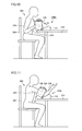
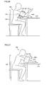
- a main unit 110 and a living body insert portion 140 are formed in two pieces, and are connected in a pivotable manner via a pivot 145 provided on the rear end of main unit 110.
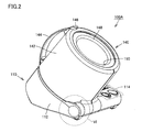
- living body insert portion 140 located on top of main unit 110 in a non-use state, is tilted backward (in a direction shown by an arrow H in the figure) as a subject 300 inserts the arm, and the inclination angle of living body insert portion 140 is adjusted in accordance with the subject's posture upon measurement. This enables accurate measurement of the blood pressure value, without restricting the posture of the subject to cause pain.
- living body insert portion 140 is tilted backward (in the direction of arrow H in the figure). This means that living body insert portion 140 moves with respect to main unit 110 in a direction opposite to the side of subject 300.
- subject 300 is required to slouch forward to follow the movement of living body insert portion 140.
- in order for subject 300 to apply the cuff on upper arm 320 he/she needs to slouch forward on the side of desk 210 and keep the relevant posture for several tens of seconds during the measurement. This makes subject 300 suffer pain until the end of measurement.
- An object of the present invention is to provide a blood pressure measuring device provided with an automatic cuff winding mechanism that enables measurement of a blood pressure value with high accuracy, hardly causes pain to a subject during the measurement, and allows the subject to keep an unconstrained posture during the measurement.
- the blood pressure measuring device includes: a first enclosure rested on a table; a second enclosure located on the first enclosure in a non-use state and having a cuff arranged on its inner peripheral surface, the cuff having a hollow opening to which a portion of a living body of a subject is inserted; and a connection mechanism for connecting the second enclosure with the first enclosure in a movable manner such that, upon application of the cuff to the subject, the second enclosure can move to come closer to the subject than the first enclosure.
- the blood pressure measuring device further includes an inclination level detecting portion for detecting an inclination level of the second enclosure.
- the blood pressure measuring device further includes an informing portion for informing the subject of a result of determination as to whether the inclination level of the second enclosure detected by the inclination level detecting portion is within a predetermined range.
- the blood pressure measuring device further includes a control unit for determining whether the inclination level of the second enclosure detected by the inclination level detecting portion is within a predetermined range, and when it is out of the predetermined range, for controlling to terminate a measurement operation when it is already in progress, and not to enter a measurement operation when it is yet to be started.
- the inclination level detecting portion may be one for detecting an inclination angle of the second enclosure with respect to a horizontal plane.
- the inclination level detecting portion may be one for detecting an inclination angle of the second enclosure with respect to the first enclosure.
- the inclination level detecting portion may be one for detecting an amount of movement of the second enclosure with respect to the first enclosure.
- connection mechanism may be formed of a pivot connection mechanism including a pivot that supports the second enclosure with respect to the first enclosure in a pivotable manner.
- the pivot is preferably provided at an end of the first enclosure on the subject side.
- torque required to be applied to the pivot to move the second enclosure is smaller than torque that is imposed on the pivot in accordance with a change in pressure of the cuff during the measurement.
- the pivot connection mechanism preferably includes at least one of a dumper and a friction spring for suppressing abrupt pivotal movement of the second enclosure.
- the pivot connection mechanism preferably further includes a bias portion for biasing the second enclosure in a direction away from the first enclosure in a non-use state, and a locking portion for locking the second enclosure with the first enclosure in opposition to bias force of the bias portion in the non-use state.
- connection mechanism may be formed of a slide connection mechanism that supports the second enclosure with respect to the first enclosure in a slidable manner.
- the subject can take an unforced posture during the measurement, without suffering pain, so that accurate and stable measurement of the blood pressure value becomes possible.
- a blood pressure monitor detects arterial pressure pulse waves by pressing an upper arm of a subject, to measure a blood pressure value.
- the blood pressure monitor of the present embodiment is provided with an automatic cuff winding mechanism to wind a cuff around the upper arm.
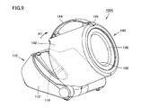
- the blood pressure monitor 100A primarily includes a main unit 110 placed on a table or the like, and a living body insert portion 140 having a hollow opening 150 to which a portion of a living body (an upper arm in the case of blood pressure monitor 100A of the present embodiment) of a subject is inserted.
- Main unit 110 is covered with a casing for the main unit (hereinafter, referred to as the "main unit casing") 112 that is a first enclosure
- living body insert portion 140 is covered with a casing for the living body insert portion (hereinafter, referred to as the "living body insert portion casing") 142 that is a second enclosure.
- main unit 110 Provided on the upper surface of main unit 110 is a control portion 114 having various buttons arranged therein, which include a power supply button for turning the power on, a measurement button for starting a measurement operation, a display portion control button for controlling a display portion, and others.
- a display portion 116 is provided on another part of the upper surface of main unit 110, for displaying a result of the measurement, operating guides and others.
- An elbow rest 119 for resting the elbow when the subject takes a posture for measurement is provided at a prescribed position on the upper surface of main unit 110, adjacent to control portion 114 and display portion 116 (see Fig. 9). This elbow rest 119 is, for example, a depression provided on the upper surface of main unit casing 112.
- Living body insert portion 140 is connected to main unit 110 in a pivotable manner by means of a pivot connection mechanism including a pivot.
- a pivot connection mechanism including a pivot.
- the pivot arranged within main unit casing 112 to the front end of main unit 110 facing the subject connects main unit casing 112 with living body insert portion casing 142 in a pivotable manner.
- Living body insert portion 140 includes a cuff arranged on the inner peripheral surface of living body insert portion casing 142 of an approximately cylindrical shape, and a cuff cover 148 attached to living body insert portion casing 142 to cover the cuff.
- a handle 144 is also provided at a prescribed position on the outer peripheral surface of living body insert portion casing 142, which is used by a subject to pivotally move living body insert portion 140.
- an unlocking button 146 is provided in the vicinity of handle 144, which is used to allow pivotal movement of living body insert portion casing 142 rested on main unit 110. Unlocking button 146 and an unlocking/locking mechanism cooperating therewith will be described later.
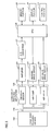
- a living body pressing air bag 152 included in the cuff is connected via an air tube 154 to a living body pressing air system 120.
- a CPU (central processing unit) 128 controls an operation of living body pressing air system 120.
- Living body pressing air system 120 includes an air pump 121, an air valve 122, and a pressure sensor 123.
- Air pump 121 is provided for pressurizing a bladder of living body pressing air bag 152, which is driven by an air pump drive circuit 124 having received a command from CPU 128. Upon measurement, air pump 121 introduces compressed gas into the bladder of living body pressing air bag 152 to make it attain a prescribed pressure.
- Air valve 122 is provided for keeping or reducing the pressure in the bladder of living body pressing air bag 152, which is controlled to open and close by an air valve drive circuit 125 having received a command from CPU 128.
- air valve 122 Upon measurement, air valve 122 functions to keep and reduce the pressure of the bladder of living body pressing air bag 152 having attained a high-pressure state by air pump 121. After completion of the measurement, air valve 122 causes the bladder of living body pressing air bag 152 to return to the atmospheric pressure.
- Pressure sensor 123 is provided for detecting a pressure of the bladder of living body pressing air bag 152.
- pressure sensor 123 detects the pressure of the bladder of living body pressing air bag 152 that changes from moment to moment, and outputs signals corresponding to the detected values to an amplifier 126.
- Amplifier 126 amplifies the signals output from pressure sensor 123 and outputs the amplified signals to an A/D converter 127.
- A/D converter 127 digitalizes the analog signals received from amplifier 126, and outputs the resultant signals to CPU 128.
- CPU 128 controls living body pressing air system 120 based on commands input via control portion 114 provided at main unit 110 of blood pressure monitor 100A, and outputs a result of measurement to display portion 116 and a memory portion 129.
- Memory portion 129 is provided for storing the measurement results.
- all the functional blocks shown in Fig. 3 except for living body pressing air bag 152 and pressure sensor 123 are provided at main unit 110, and accommodated in main unit casing 112.
- Living body pressing air bag 152 and pressure sensor 123 are provided at living body insert portion 140, and accommodated in living body insert portion casing 142.
- Living body pressing air bag 152, air pump 121 and air valve 122 are connected via a flexible air tube, and pressure sensor 123 and amplifier 126 are connected via a flexible signal line.
- the flexible air tube and the flexible signal line used to connect the components accommodated in main unit casing 112 and those accommodated in living body insert portion casing 142 can follow the pivotal movement of living body insert portion casing 142 to enable injection/discharge of the air and transmission/reception of the signals.
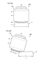
- main unit casing 112 and living body insert portion casing 142 are separated from each other, and the pivot connection mechanism including a pivot connects the separated main unit casing 112 and living body insert portion casing 142.
- living body insert portion casing 142 is rested on main unit casing 112.
- the upper surface of main unit casing 112 is formed slopewise in advance such that when it is placed on a horizontal table or the like, it is arranged at a prescribed angle with respect to the horizontal plane.
- Living body insert portion casing 142 is rested on main unit casing 112 in such a manner that the axis line of hollow opening 150 of living body insert portion casing 142 is orthogonal to the upper surface of main unit casing 112 thus inclined.
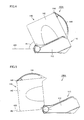
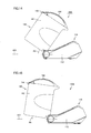
- the inclination angle of living body insert portion casing 142 with respect to the horizontal plane in the non-use state is represented as R1.
- the pivotal movement of living body insert portion casing 142 caused by a subject is restricted within a pivotally movable range.
- living body insert portion casing 142 attains a maximum moved state to the side of the subject within the movable range, living body insert portion casing 142 comes closer to the subject than main unit casing 112.
- the axis line of hollow opening 150 is tilted to the extent slightly beyond the state parallel to the horizontal plane.
- the inclination angle of living body insert portion casing 142 with respect to the horizontal plane in the maximum moved state is represented as R2.
- living body insert portion casing 142 can pivotally move freely, by an operation of the subject, within the movable range from the position corresponding to the non-use state shown in Fig. 4 to the position corresponding to the maximum moved state shown in Fig. 5.
- living body insert portion casing 142 pivotally moves from the position in the non-use state to approach the subject within the range of the angle (R1 + R2).
- torque required to be applied to the pivot to pivotally move living body insert portion casing 142 is smaller than torque that is imposed on the pivot during the measurement in accordance with the change in pressure of the cuff, or the torque that is applied to the pivot by living body insert portion casing 142 during the measurement when living body insert portion casing 142 is pressed by inflation or deflation of the cuff.
- the torque of the pivot is adjusted in this manner, the movement of living body insert portion casing 142 in accordance with the change in pressure of the cuff during the measurement is no longer restricted.
- contact of the cuff with the living body improves, and blood pressure can be measured with high accuracy.
- the pivot connection mechanism may also include a dumper or a friction spring for the purpose of suppressing abrupt pivotal movement of living body insert portion casing 142.
- the dumper or the friction spring may be provided at a connecting portion between the pivot and living body insert portion casing 142 or/and main unit casing 112. This configuration can suppress abrupt pivotal movement of living body insert portion casing 142 for example when the subject suddenly changes the posture during the measurement, so that occurrence of an artifact error due to detection of abnormal pressure pulse waves can be prevented. Further, operability for adjusting living body insert portion casing 142 to a desired angle when applying the cuff to the living body can be improved.
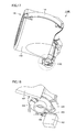
- Fig. 6 shows an embodiment in the case where the above-described pivot connection mechanism is provided with the friction spring in the form of a coil spring.
- part of the main unit casing is not illustrated for ease of understanding of the shape of the coil spring.
- the pivot connection mechanism includes, in addition to the pivot, a coil spring 130 as the bias portion for biasing living body insert portion casing 142 in a direction away from main unit casing 112 in the non-use state.
- coil spring 130 has an end secured to main unit casing 112, and another end 132 secured to living body insert portion casing 142. With this configuration, coil spring 130 suppresses abrupt pivotal movement of living body insert portion casing 142.
- living body insert portion casing 142 is rested on and secured to main unit casing 112 in the non-use state. That is, in the non-use state, living body insert portion casing 142 is secured to main unit casing 112 by the locking portion in opposition to the elastic bias force of coil spring 130 serving as the above-described bias portion.
- the locking portion is formed of a hook 117 provided at main unit casing 112 and another hook 143 provided at living body insert portion casing 142.
- an unlocking lever 147 cooperating with unlocking button 146 extends inside living body insert portion casing 142.
- An end 147a of unlocking lever 147 reaches main unit casing 112, and abuts hook 117 provided at main unit casing 112.
- An end 117a of hook 117 is engaged with hook 143 provided at living body insert portion casing 142, and coil spring 118 elastically biases hook 117 to maintain the engagement.
- unlocking lever 147 moves in the direction shown by an arrow B in the figure, and end 147a of unlocking lever 147 presses downward a tapered surface provided at the upper end of hook 117.
- end 117a of hook 117 is disconnected from hook 143 of living body insert portion casing 142, as shown in Fig. 8C, and the lock of living body insert portion casing 142 with main unit casing 112 is released. This enables pivotal movement of living body insert portion casing 142 with respect to main unit casing 112.
- living body insert portion casing 142 is pressed upward by the bias force of the above-described coil spring 130 shown in Fig. 6 to the position shown in Fig. 9. Specifically, living body insert portion casing 142 pivotally moves about the pivot toward the subject to come closer to the subject than main unit casing 112, and stops at a position where its own weight balances with the elastic bias force of coil spring 130. It is noted that the position where living body insert portion casing 142 stops moving after the unlocking operation may be set to a desired angle by altering the elastic bias force of coil spring 130 as well as the own weight of living body insert portion casing 142 as appropriate.
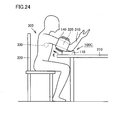
- main unit 110 of blood pressure monitor 100A is placed on a desk 210 having a horizontal surface, and a subject 300 sits on a chair 220. Depressing unlocking button 146, subject 300 moves living body insert portion 140 in the direction shown by an arrow A1 in the figure. Subject 300 then inserts the right hand into hollow opening 150 of living body insert portion 140, while gripping handle 144 provided at living body insert portion casing 142 of blood pressure monitor 100A with the left hand to adjust the inclination angle of living body insert portion 140.
- Subject 300 inserts the right hand to the further depth of hollow opening 150, until a forearm 310 and then an upper arm 320 faces the cuff provided in living body insert portion 140. With slightly bending the elbow of the right arm inserted in hollow opening 150, subject 300 rests the elbow on elbow rest 119 provided at the upper surface of main unit 110, to thereby take the posture for measurement as shown in Fig. 11.
- the inclination angle of living body insert portion 140 changes in accordance with the inclination angle of the right arm. Specifically, living body insert portion 140 turns following the movement of the right hand, as the right hand and then the right arm inserted in hollow opening 150 of living body insert portion 140 contact the inner peripheral surface of hollow opening 150. For example, at the stage where the right hand is inserted, it is preferable that living body insert portion 140 is turned in advance to the position corresponding to the maximum moved state as shown in Fig. 10 or closer thereto, to reduce the burden imposed on the subject.
- living body insert portion 140 pivotally moves in the direction shown by an arrow A2 in the figure in accordance with the movement of the right hand and arm.
- the torque required to be applied to the pivot to rotate living body insert portion 140 is adjusted to allow living body insert portion 140 to follow the movement of the right hand and arm
- blood pressure monitor 100A of the present embodiment arterial pressure pulse waves caused in the artery located within upper arm 320 by inflation/deflation of living body pressing air bag 152 are detected to measure the blood pressure value.
- living body insert portion 140 rotates following the movement of the upper arm This ensures good contact between the cuff and the living body, and measurement with high accuracy becomes possible.
- the subject can take an unconstrained posture during the measurement under any conditions, without suffering unnecessary pain. As a result, it is possible to stably and accurately measure the blood pressure value.
- a blood pressure monitor is identical to that of the first embodiment in that it detects arterial pressure pulse waves by pressing an upper arm of a subject to measure a blood pressure value and also in that the cuff is wound around the upper arm automatically by an automatic cuff winding mechanism.
- the portions similar to those of the blood pressure monitor of the first embodiment are denoted by the same reference characters, and description thereof will not be repeated here.
- the living body insert portion casing and the main unit casing are connected to each other by a pivot connection mechanism including a pivot, as in the blood pressure monitor of the first embodiment.
- the living body insert portion casing moves with respect to the main unit casing in a pivotable manner, for which a wide movable range is ensured such that the subject can readily insert the arm to apply the cuff, again as in the blood pressure monitor of the first embodiment.
- the blood pressure monitor configured as described above, however, there may occur a case where a blood pressure value can be measured without hindrance even if the posture of the subject is not suitable for the measurement. Such a risk increases as the movable range of the living body insert portion casing is set wider. Accuracy in measurement may be degraded if there is a considerable difference in height between the upper arm around which the cuff is wound and the heart.
- the inclination level detecting portion for detecting an inclination level of the living body insert portion casing is provided to solve such a problem.
- the inclination level of the living body insert portion casing refers to the degree of inclination of the living body insert portion casing, which may be derived from the inclination angle with respect to the horizontal plane, the inclination angle with respect to the main unit casing, or an amount of movement of the living body insert portion casing with respect to the main unit casing.
- the blood pressure monitor 100B of the present embodiment is provided with an inclination level detecting portion 160, and information about the inclination level of living body insert portion casing 142 detected by inclination level detecting portion 160 is output to CPU 128.
- an optimal range for the inclination angle of the upper arm inserted into hollow opening 150 of living body insert portion 140 is necessarily derived.
- the optimal range for the inclination angle of the upper arm corresponds to the inclination level of living body insert portion casing 142 at the time of measurement, and as a result, an optimal measurement range of living body insert portion casing 142 is decided.
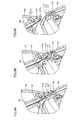
- Fig. 14 shows the state where the living body insert portion casing is in a minimum moved position within the optimal measurement range enabling accurate measurement of the blood pressure value.
- the inclination angle of living body insert portion casing 142 with respect to the horizontal plane in this state is represented as R3.
- Fig. 15 shows the state where the living body insert portion casing is in a maximum moved position within the optimal measurement range enabling accurate measurement of the blood pressure value.
- the inclination angle of living body insert portion casing 142 with respect to the horizontal plane in this state is represented as R4.
- living body insert portion casing 142 freely turns within a movable range that is defined by inclination angles R1 and R2 shown in the figure.
- the optimal measurement range of living body insert portion casing 142 corresponds to the range from inclination angle R3 to inclination angle R4 shown in the figure.
- the optimal measurement range is included in the movable range, and has the inclination angle with respect to the horizontal plane preferably within the range from 15° to 45°.
- the inclination level detecting portion for detecting whether living body insert portion casing 142 is within the optimal measurement range or not application of various sensors is conceivable.
- an angle sensor or the like may be employed as the means for directly detecting the inclination angle of living body insert portion casing 142 with respect to the horizontal plane or its inclination angle with respect to main unit casing 112
- a range sensor as typified by a photoelectric sensor (proximity sensor), a photoelectric sensor employing an encoder system, and the like may be employed.
- the inclination level may be detected using various switches.
- a tact switch, a rotary switch, a switch employing variable resistance, and the like may be used to detect the inclination angle of living body insert portion casing 142 indirectly from the amount of movement of living body insert portion casing 142.
- a rotary plate 134 is attached to an end of the pivot connecting living body insert portion casing 142 and main unit casing 112.
- Rotary plate 134 turns corresponding to the turn of living body insert portion casing 142.
- a projection 136 is provided on the surface of rotary plate 134, which differs in height from another area 135 of the surface.
- a tact switch 162 serving as the inclination level detecting portion is arranged in the vicinity of rotary plate 134.
- a switch level 164 of tact switch 162 abuts the main surface of rotary plate 134 on which projection 136 is provided.
- Projection 136 of rotary plate 134 is formed to have a predetermined width in angle in the circumferential direction. Specifically, it is formed to have the angle width the same as the angle defining the optimal measurement range of living body insert portion casing 142 described above.
- Switch lever 164 facing the main surface of rotary plate 134 provided with projection 136, causes tact switch 162 to attain an on state when it abuts projection 136, and to attain an off state when it abuts other area 135 not provided with projection 136.
- tact switch 162 attains the on state when living body insert portion casing 142 is located within the optimal measurement range, whereas it attains the off state when living body insert portion casing 152 is located out of the optimal measurement range.
- a result of the determination may be used, e.g., for an informing system that informs the subject as to whether the posture for measurement is acceptable or not.
- an informing system that informs the subject as to whether the posture for measurement is acceptable or not.
- step S0 the power supply button is turned on to make blood pressure monitor 100B enter a standby state.
- the inclination level of living body insert portion casing 142 is detected (step S1).
- the inclination level of living body insert portion casing 142 detected in step S 1 is output to CPU 128, and, in step S2, it is determined whether it is within the optimal measurement range. If the inclination level of living body insert portion casing 142 is within the optimal measurement range, the process goes to step S3 where blood pressure monitor 100B enters a standby state for measurement. If it is out of the optimal measurement range, warning is given to the subject in step S4. The way of giving warning will be described later.
- Blood pressure monitor 100B having entered the measurement standby state in step S3 proceeds to the step (step S6) of detecting the inclination level of living body insert portion casing 142 again when the subject turns on a pressurization button (step S5). During this time, the inflating and deflating operations of the cuff are carried out, and detection of the arterial pressure pulse waves by the pressure sensor is conducted concurrently.
- step S7 if it is determined that the inclination level of living body insert portion casing 142 is within the optimal measurement range, the process goes to step S8, where the measurement is finished. If it is determined that the inclination level of living body insert portion casing 142 is out of the optimal measurement range in step S7, the process goes to step S9, where warning is given to the subject or the measurement operation is forcibly terminated.
- a warning display may be provided on the display portion, a warning sound may be emitted by a buzzer or the like, an LED (light-emitting diode) provided at the main unit or the living body insert portion of the blood pressure monitor may be turned on, or the blood pressure monitor itself may be made to vibrate.
- a configuration of the display portion in the case where a liquid crystal display is used to display a warning to attract attention of the subject will be described.
- display portion 116 displays a value indicating the pressure within the living body pressing air bag, a label of the subject, and time.
- a warning mark is displayed on a prescribed position of display portion 116, as shown in Fig. 20B.
- display portion 116 displays a pressure within the living body pressing air bag, a label of the subject, and time. In this state, if it is determined that the inclination level of living body insert portion casing 142 is out of the optimal measurement range, a warning mark is displayed on a prescribed position of display portion 116, as shown in Fig. 21B.
- display portion 116 displays the systolic blood pressure value and the diatolic blood pressure value measured in the past, a label of the subject, a heart rate, and time.
- a warning mark is displayed on a prescribed position of display portion 116, as shown in Fig. 22B.
- an adverse effect caused by ensuring a wide movable range of the living body insert portion casing can be prevented, and the intended purpose to make it possible to accurately measure the blood pressure value with an unforced posture is accomplished.
- main unit casing 112 and living body insert portion casing 142 are slidably connected by a slide connection mechanism.
- the slide connection mechanism is formed, e.g., of a ridge 149 provided at the lower end of living body insert portion casing 142 with a prescribed radius of curvature, and a guide groove provided at the upper end of main unit casing 112 with a prescribed radius of curvature. Engagement of ridge 149 with the guide groove realizes the connection between living body insert portion casing 142 and main unit casing 112 in a slidable manner.
- living body insert portion casing 142 moves toward the subject (in the direction shown by an arrow E in the figure) with respect to main unit casing 112.
- ridge 149 and the guide groove are both provided with a prescribed radius of curvature, so that living body insert portion casing 142 is inclined as it moves.
- the posture for measurement as shown in Fig. 24 is realized, and similar effects to those of the first embodiment described above can be obtained.
- the subject does not need to suffer unnecessary pain during the measurement, and the measurement can be carried out with an unconstrained posture under any conditions. Accordingly, accurate and stable measurement of the blood pressure value becomes possible.
- main unit casing 112 and living body insert portion casing 142 are slidably and pivotally connected via a slide connection mechanism and a pivot connection mechanism.
- the slide connection mechanism is formed, e.g., of a ridge 149 provided at the lower end of living body insert portion casing 142 and a guide groove provided at the upper end of main unit casing 112, and ridge 149 and the guide groove are engaged with each other to connect living body insert portion casing 142 with main unit casing 112 in a slidable manner.
- the pivot connection mechanism is formed, e.g., of a pivot 145 provided at the rear end of living body insert portion casing 142 and the guide groove of main unit casing 112, and engagement of pivot 145 with the guide groove connects living body insert portion casing 142 with main unit casing 112 in a pivotable manner.
- living body insert portion casing 142 Upon application of the cuff to the upper arm, as shown in Fig. 25B, living body insert portion casing 142 is moved toward the subject (in the direction shown by an arrow F in the figure) with respect to main unit casing 112, to insert the arm into hollow opening 150 of living body insert portion 140. In the state where the arm is inserted, living body insert portion casing 142 pivotally moves (in the direction shown by an arrow G in the figure) in accordance with the movement of the arm, so that the posture for measurement as shown in Fig. 25B is realized.
- the blood pressure monitor according to the third or fourth embodiment may be provided with the inclination level detecting portion as in the blood pressure monitor of the second embodiment, to make it possible to inform the subject when the inclination level is out of the optimal measurement range and/or to inhibit measurement of the blood pressure at that time.
- the blood pressure monitor according to the third or fourth embodiment may also be provided with a dumper, a friction spring, and/or a coil spring or the like to cause the living body insert portion casing to move to a prescribed position when the unlocking button is manipulated, to realize a blood pressure monitor excellent in operability.
- the upper arm blood pressure monitor for measuring a blood pressure value by pressing an upper arm has been explained by way of example.
- the present invention is of course applicable to a wrist blood pressure monitor. Further, not limited to the blood pressure monitors, the present invention is applicable to a pulse wave detecting device and others as well.
Abstract
Description
Claims (13)
- A blood pressure measuring device, comprising:a first enclosure (112) rested on a table;a second enclosure (142) located on said first enclosure (112) in a non-use state and having a cuff arranged on its inner peripheral surface, the cuff having a hollow opening (150) to which a portion of a living body of a subject is inserted; anda connection mechanism for connecting said second enclosure (142) with said first enclosure (112) in a movable manner such that, upon application of said cuff to the subject, said second enclosure (142) can move to come closer to the subject than said first enclosure (112).
- The blood pressure measuring device according to claim 1, further comprising an inclination level detecting portion (160) for detecting an inclination level of said second enclosure (142).
- The blood pressure measuring device according to claim 2, further comprising an informing portion (116) for informing the subject of a result of determination as to whether the inclination level of said second enclosure (142) detected by said inclination level detecting portion (160) is within a predetermined range.
- The blood pressure measuring device according to claim 2, further comprising a control portion (128) for determining whether the inclination level of said second enclosure (142) detected by said inclination level detecting portion (160) is within a predetermined range, and when it is out of said predetermined range, for controlling to terminate a measurement operation when it is already in progress, and not to enter a measurement operation when it is yet to be started.
- The blood pressure measuring device according to claim 2, wherein said inclination level detecting portion (160) detects an inclination angle of said second enclosure (142) with respect to a horizontal plane.
- The blood pressure measuring device according to claim 2, wherein said inclination level detecting portion (160) detects an inclination angle of said second enclosure (142) with respect to said first enclosure (112).
- The blood pressure measuring device according to claim 2, wherein said inclination level detecting portion (160) detects an amount of movement of said second enclosure (142) with respect to said first enclosure (112).
- The blood pressure measuring device according to claim 1, wherein said connection mechanism is formed of a pivot connection mechanism including a pivot that supports said second enclosure (142) with respect to said first enclosure (112) in a pivotable manner.
- The blood pressure measuring device according to claim 8, wherein said pivot is provided at an end of said first enclosure (112) on the subject side.
- The blood pressure measuring device according to claim 8, wherein torque required to be applied to said pivot to move said second enclosure (142) is smaller than torque that is imposed on said pivot in accordance with a change in pressure of said cuff during the measurement.
- The blood pressure measuring device according to claim 8, wherein said pivot connection mechanism includes at least one of a dumper and a friction spring (130) for suppressing abrupt pivotal movement of said second enclosure (142).
- The blood pressure measuring device according to claim 8, wherein said pivot connection mechanism further includes a bias portion (130) for biasing said second enclosure (142) in a direction away from said first enclosure (112) in a non-use state, and a locking portion (117, 143) for locking said second enclosure (142) with said first enclosure (112) in opposition to bias force of said bias portion (130) in the non-use state.
- The blood pressure measuring device according to claim 1, wherein said connection mechanism is formed of a slide connection mechanism that supports said second enclosure (142) with respect to said first enclosure (112) in a slidable manner.
Applications Claiming Priority (2)
| Application Number | Priority Date | Filing Date | Title |
|---|---|---|---|
| JP2004054362 | 2004-02-27 | ||
| JP2004054362A JP3818295B2 (en) | 2004-02-27 | 2004-02-27 | Blood pressure measurement device |
Publications (2)
| Publication Number | Publication Date |
|---|---|
| EP1568313A1 true EP1568313A1 (en) | 2005-08-31 |
| EP1568313B1 EP1568313B1 (en) | 2021-06-02 |
Family
ID=34747560
Family Applications (1)
| Application Number | Title | Priority Date | Filing Date |
|---|---|---|---|
| EP05003570.8A Expired - Fee Related EP1568313B1 (en) | 2004-02-27 | 2005-02-18 | Blood pressure measuring device |
Country Status (4)
| Country | Link |
|---|---|
| US (1) | US7316653B2 (en) |
| EP (1) | EP1568313B1 (en) |
| JP (1) | JP3818295B2 (en) |
| CN (1) | CN1331438C (en) |
Cited By (5)
| Publication number | Priority date | Publication date | Assignee | Title |
|---|---|---|---|---|
| EP1932468A2 (en) | 2006-12-14 | 2008-06-18 | Matsushita Electric Works, Ltd. | Sphygmomanometer |
| EP1932469A2 (en) | 2006-12-14 | 2008-06-18 | Matsushita Electric Works, Ltd. | Sphygmomanometer |
| US7775984B2 (en) | 2005-08-12 | 2010-08-17 | Omron Healthcare Co., Ltd. | Electronic blood pressure monitor and data processing apparatus |
| RU2444283C2 (en) * | 2007-11-06 | 2012-03-10 | Омрон Хэлткэа Ко., Лтд. | Device for measuring blood pressure |
| FR3042697A1 (en) * | 2015-10-26 | 2017-04-28 | Faou Daniel Jean Marie Michel Le | STORAGE CASE FOR WRENCH TENSIOMETER |
Families Citing this family (26)
| Publication number | Priority date | Publication date | Assignee | Title |
|---|---|---|---|---|
| JP3818295B2 (en) | 2004-02-27 | 2006-09-06 | オムロンヘルスケア株式会社 | Blood pressure measurement device |
| JP4595449B2 (en) * | 2004-09-02 | 2010-12-08 | オムロンヘルスケア株式会社 | Sphygmomanometer cuff |
| US8439998B2 (en) * | 2004-12-06 | 2013-05-14 | Sunrex Kogyo Co., Ltd. | Manufacturing method of metal product and metal product |
| US20060184053A1 (en) * | 2005-02-15 | 2006-08-17 | Health & Life Co., Ltd. | Tunnel type sphygmomanometer assembly |
| US7060034B1 (en) * | 2005-03-15 | 2006-06-13 | Health & Life Co., Ltd. | Tunnel type electronic sphygmomanometer measuring unit assembly |
| JP3125595U (en) * | 2006-05-25 | 2006-09-28 | 日本精密測器株式会社 | Wrist blood pressure monitor |
| JP4730332B2 (en) * | 2007-04-24 | 2011-07-20 | オムロンヘルスケア株式会社 | Blood pressure measurement device and measurement data processing program |
| US20090036759A1 (en) * | 2007-08-01 | 2009-02-05 | Ault Timothy E | Collapsible noninvasive analyzer method and apparatus |
| US20090137914A1 (en) * | 2007-11-26 | 2009-05-28 | National Yang-Ming University | Portable hydraulic sphygmomanometer |
| US20090198109A1 (en) * | 2008-02-06 | 2009-08-06 | Health & Life Co., Ltd. | Method and apparatus for guided operating instruction for physiological measuring instrument |
| JP5092779B2 (en) * | 2008-02-13 | 2012-12-05 | オムロンヘルスケア株式会社 | Blood pressure measurement device |
| JP5200907B2 (en) * | 2008-12-12 | 2013-06-05 | オムロンヘルスケア株式会社 | Blood pressure measurement device |
| CN102264284A (en) * | 2008-12-23 | 2011-11-30 | 模拟技术公司 | Blood pressure cuff |
| JP5200953B2 (en) * | 2009-01-22 | 2013-06-05 | オムロンヘルスケア株式会社 | Blood pressure measurement device |
| JP5313735B2 (en) * | 2009-03-24 | 2013-10-09 | テルモ株式会社 | Electronic blood pressure monitor |
| US9492092B2 (en) * | 2009-05-20 | 2016-11-15 | Sotera Wireless, Inc. | Method for continuously monitoring a patient using a body-worn device and associated system for alarms/alerts |
| JP5287572B2 (en) * | 2009-07-23 | 2013-09-11 | オムロンヘルスケア株式会社 | Sphygmomanometer |
| US8211029B2 (en) * | 2009-08-27 | 2012-07-03 | Memsic, Inc. | Devices, systems, and methods for accurate blood pressure measurement |
| DE102011111030A1 (en) * | 2010-12-24 | 2012-06-28 | Paul Hartmann Ag | Blood pressure measuring cuff |
| DE102010056241A1 (en) * | 2010-12-24 | 2012-06-28 | Paul Hartmann Ag | Blood pressure measuring cuff |
| EP2677925A4 (en) * | 2011-02-27 | 2015-08-12 | Eitan Mardiks | Apparatus and method for real-time measurement of changes in volume of breast and other organs |
| US20140350418A1 (en) * | 2013-05-21 | 2014-11-27 | Pharma-Smart Internation, Inc. | Blood pressure kiosk for use with left or right arm |
| JP7010120B2 (en) * | 2018-04-10 | 2022-01-26 | オムロンヘルスケア株式会社 | Sphygmomanometer |
| JP7070022B2 (en) * | 2018-04-20 | 2022-05-18 | オムロンヘルスケア株式会社 | Sphygmomanometer |
| CN109222940A (en) * | 2018-10-26 | 2019-01-18 | 南通市第人民医院 | The device of heart present position is proofreaded when a kind of measurement blood pressure |
| CN116965789B (en) * | 2023-06-30 | 2023-12-29 | 东莞一测科技有限公司 | Tunnel electronic sphygmomanometer and assembling method |
Citations (6)
| Publication number | Priority date | Publication date | Assignee | Title |
|---|---|---|---|---|
| DE2837707A1 (en) * | 1978-08-30 | 1980-03-13 | Richard Dr Med Humpert | Inflatable sleeve for blood pressure measuring device - is carried inside curved swinging halves forming loop around upper arm when closed |
| JPS63305841A (en) * | 1987-06-09 | 1988-12-13 | Omron Tateisi Electronics Co | Digital electronic hemomanometer |
| EP0415288A1 (en) * | 1989-08-25 | 1991-03-06 | Toto Ltd. | Toilet device with system for inspecting health conditions |
| EP0700657A1 (en) * | 1994-03-25 | 1996-03-13 | Toto Ltd. | Toilet-installed digital sphygmomanometer with retractable cuff |
| US5778879A (en) * | 1995-02-16 | 1998-07-14 | Omron Corporation | Electronic blood pressure meter with posture detector |
| US6413224B1 (en) * | 1994-02-25 | 2002-07-02 | Colin Corporation | Blood pressure measuring apparatus |
Family Cites Families (19)
| Publication number | Priority date | Publication date | Assignee | Title |
|---|---|---|---|---|
| JPS5529303A (en) | 1978-08-21 | 1980-03-01 | Fuji Electric Co Ltd | Cuff automatic winder |
| JPS57180939A (en) * | 1981-04-30 | 1982-11-08 | Fuji Denki Sogo Kenkyusho Kk | Cuff automatic take-up apparatus |
| JPS57180940A (en) | 1981-04-30 | 1982-11-08 | Fuji Denki Sogo Kenkyusho Kk | Automatic arm band winding mechanism for blood pressure measuring apparatus |
| JPS58117604A (en) | 1981-12-29 | 1983-07-13 | 松下電工株式会社 | Noise reducer for discharge lamp lighting apparatus |
| US4859467A (en) | 1986-09-25 | 1989-08-22 | Colgate-Palmotive Company | Sustained release fluoride composition |
| US5218966A (en) * | 1987-06-12 | 1993-06-15 | Omron Tateisi Electronics Co. | Electronic blood pressure meter |
| JPH02135003A (en) | 1988-11-16 | 1990-05-23 | Iseki & Co Ltd | Apparatus for controlling direction of combine |
| US5069219A (en) * | 1989-12-20 | 1991-12-03 | Spacelabs, Inc. | Self snugging universal blood pressure cuff |
| FR2664158B1 (en) * | 1990-07-06 | 1995-06-16 | Oreal | SKIN MASSAGE APPARATUS, EQUIPPED WITH ORIENTED ROTATING ELEMENTS. |
| JPH10314125A (en) | 1997-05-21 | 1998-12-02 | Nippon Colin Co Ltd | Blood pressure measuring arm band device |
| JPH10314123A (en) | 1997-05-21 | 1998-12-02 | Nippon Colin Co Ltd | Arm band winding instrument for measuring blood pressure |
| JP2000041958A (en) | 1998-07-27 | 2000-02-15 | Nippon Colin Co Ltd | Automatic sphygmomanometry instrument |
| US6428124B1 (en) * | 2000-04-14 | 2002-08-06 | Computerized Screening, Inc. | Health care kiosk with handicapped accessible seat |
| WO2002039893A1 (en) * | 2000-11-14 | 2002-05-23 | Omron Corporation | Electronic sphygmomanometer |
| JP2002159351A (en) | 2000-11-27 | 2002-06-04 | Nakabayashi Co Ltd | Small article housing box |
| US6471657B2 (en) * | 2001-01-31 | 2002-10-29 | Spacelabs Medical, Inc. | User releasable and adjustable blood pressure cuff and method |
| JP3966188B2 (en) | 2003-02-26 | 2007-08-29 | 松下電工株式会社 | Sphygmomanometer |
| JP3826938B2 (en) | 2004-02-18 | 2006-09-27 | オムロンヘルスケア株式会社 | Sphygmomanometer |
| JP3818295B2 (en) | 2004-02-27 | 2006-09-06 | オムロンヘルスケア株式会社 | Blood pressure measurement device |
-
2004
- 2004-02-27 JP JP2004054362A patent/JP3818295B2/en not_active Expired - Lifetime
-
2005
- 2005-02-18 EP EP05003570.8A patent/EP1568313B1/en not_active Expired - Fee Related
- 2005-02-23 US US11/062,964 patent/US7316653B2/en active Active
- 2005-02-28 CN CNB2005100525049A patent/CN1331438C/en active Active
Patent Citations (6)
| Publication number | Priority date | Publication date | Assignee | Title |
|---|---|---|---|---|
| DE2837707A1 (en) * | 1978-08-30 | 1980-03-13 | Richard Dr Med Humpert | Inflatable sleeve for blood pressure measuring device - is carried inside curved swinging halves forming loop around upper arm when closed |
| JPS63305841A (en) * | 1987-06-09 | 1988-12-13 | Omron Tateisi Electronics Co | Digital electronic hemomanometer |
| EP0415288A1 (en) * | 1989-08-25 | 1991-03-06 | Toto Ltd. | Toilet device with system for inspecting health conditions |
| US6413224B1 (en) * | 1994-02-25 | 2002-07-02 | Colin Corporation | Blood pressure measuring apparatus |
| EP0700657A1 (en) * | 1994-03-25 | 1996-03-13 | Toto Ltd. | Toilet-installed digital sphygmomanometer with retractable cuff |
| US5778879A (en) * | 1995-02-16 | 1998-07-14 | Omron Corporation | Electronic blood pressure meter with posture detector |
Non-Patent Citations (1)
| Title |
|---|
| PATENT ABSTRACTS OF JAPAN vol. 013, no. 145 (C - 583) 10 April 1989 (1989-04-10) * |
Cited By (11)
| Publication number | Priority date | Publication date | Assignee | Title |
|---|---|---|---|---|
| US7775984B2 (en) | 2005-08-12 | 2010-08-17 | Omron Healthcare Co., Ltd. | Electronic blood pressure monitor and data processing apparatus |
| EP1932468A2 (en) | 2006-12-14 | 2008-06-18 | Matsushita Electric Works, Ltd. | Sphygmomanometer |
| EP1932469A2 (en) | 2006-12-14 | 2008-06-18 | Matsushita Electric Works, Ltd. | Sphygmomanometer |
| EP1932468A3 (en) * | 2006-12-14 | 2008-08-13 | Matsushita Electric Works, Ltd. | Sphygmomanometer |
| EP1932469A3 (en) * | 2006-12-14 | 2008-11-05 | Matsushita Electric Works, Ltd. | Sphygmomanometer |
| CN101204324B (en) * | 2006-12-14 | 2010-12-08 | 松下电工株式会社 | Sphygmomanometer |
| US8109881B2 (en) | 2006-12-14 | 2012-02-07 | Panasonic Electric Works Co., Ltd. | Sphygmomanometer |
| US8128571B2 (en) | 2006-12-14 | 2012-03-06 | Panasonic Electric Works Co., Ltd. | Sphygmomanometer |
| RU2444283C2 (en) * | 2007-11-06 | 2012-03-10 | Омрон Хэлткэа Ко., Лтд. | Device for measuring blood pressure |
| US9226668B2 (en) | 2007-11-06 | 2016-01-05 | Omron Healthcare Co., Ltd. | Blood pressure monitor |
| FR3042697A1 (en) * | 2015-10-26 | 2017-04-28 | Faou Daniel Jean Marie Michel Le | STORAGE CASE FOR WRENCH TENSIOMETER |
Also Published As
| Publication number | Publication date |
|---|---|
| US7316653B2 (en) | 2008-01-08 |
| EP1568313B1 (en) | 2021-06-02 |
| JP3818295B2 (en) | 2006-09-06 |
| US20050192501A1 (en) | 2005-09-01 |
| CN1660009A (en) | 2005-08-31 |
| JP2005237802A (en) | 2005-09-08 |
| CN1331438C (en) | 2007-08-15 |
Similar Documents
| Publication | Publication Date | Title |
|---|---|---|
| US7316653B2 (en) | Blood pressure measuring device | |
| US9226668B2 (en) | Blood pressure monitor | |
| US5649542A (en) | Continuous non-invasive blood pressure monitoring system | |
| JP3578727B2 (en) | Blood pressure waveform monitor | |
| EP1177762B1 (en) | A noninvasive blood pressure measuring method and apparatus | |
| US8753282B2 (en) | Blood pressure measurement apparatus | |
| WO2002039893A1 (en) | Electronic sphygmomanometer | |
| TW201032775A (en) | Electronic blood pressure guage | |
| EP1201184A2 (en) | Arterial-hardness evaluation apparatus | |
| WO2011010686A1 (en) | Blood pressure meter | |
| JP3261682B2 (en) | Hybrid sphygmomanometer | |
| JP2008061830A (en) | Pulse wave measuring apparatus | |
| JP3835483B2 (en) | Blood pressure measurement device | |
| US20060200028A1 (en) | Sensor-based apparatus and method for portable noninvasive monitoring of blood pressure | |
| JP2002102181A (en) | Cuff structure and electronic sphygmomanometer | |
| WO2021029258A1 (en) | Sphygmomanometer, blood pressure calculation method, and program | |
| JPH0618555B2 (en) | Photoplethysmograph | |
| JP3546838B2 (en) | Wrist sphygmomanometer | |
| US10709340B2 (en) | Automated fitted cuff blood pressure and arm circumference measuring device | |
| JPS63234945A (en) | Hemomanometer | |
| JP2021030037A (en) | Blood pressure manometer, blood pressure calculation method and program | |
| JPS63311929A (en) | Digital electronic hemomanometer | |
| JPH04312442A (en) | Electronic blood pressure gauge |
Legal Events
| Date | Code | Title | Description |
|---|---|---|---|
| PUAI | Public reference made under article 153(3) epc to a published international application that has entered the european phase |
Free format text: ORIGINAL CODE: 0009012 |
|
| AK | Designated contracting states |
Kind code of ref document: A1 Designated state(s): AT BE BG CH CY CZ DE DK EE ES FI FR GB GR HU IE IS IT LI LT LU MC NL PL PT RO SE SI SK TR |
|
| AX | Request for extension of the european patent |
Extension state: AL BA HR LV MK YU |
|
| 17P | Request for examination filed |
Effective date: 20051215 |
|
| AKX | Designation fees paid |
Designated state(s): DE ES FR GB IT |
|
| 17Q | First examination report despatched |
Effective date: 20140206 |
|
| APBK | Appeal reference recorded |
Free format text: ORIGINAL CODE: EPIDOSNREFNE |
|
| APBN | Date of receipt of notice of appeal recorded |
Free format text: ORIGINAL CODE: EPIDOSNNOA2E |
|
| APBR | Date of receipt of statement of grounds of appeal recorded |
Free format text: ORIGINAL CODE: EPIDOSNNOA3E |
|
| APAV | Appeal reference deleted |
Free format text: ORIGINAL CODE: EPIDOSDREFNE |
|
| RAP1 | Party data changed (applicant data changed or rights of an application transferred) |
Owner name: OMRON HEALTHCARE CO., LTD. |
|
| APBX | Invitation to file observations in appeal sent |
Free format text: ORIGINAL CODE: EPIDOSNOBA2E |
|
| APBZ | Receipt of observations in appeal recorded |
Free format text: ORIGINAL CODE: EPIDOSNOBA4E |
|
| APBT | Appeal procedure closed |
Free format text: ORIGINAL CODE: EPIDOSNNOA9E |
|
| GRAP | Despatch of communication of intention to grant a patent |
Free format text: ORIGINAL CODE: EPIDOSNIGR1 |
|
| STAA | Information on the status of an ep patent application or granted ep patent |
Free format text: STATUS: GRANT OF PATENT IS INTENDED |
|
| INTG | Intention to grant announced |
Effective date: 20210126 |
|
| GRAS | Grant fee paid |
Free format text: ORIGINAL CODE: EPIDOSNIGR3 |
|
| GRAA | (expected) grant |
Free format text: ORIGINAL CODE: 0009210 |
|
| STAA | Information on the status of an ep patent application or granted ep patent |
Free format text: STATUS: THE PATENT HAS BEEN GRANTED |
|
| AK | Designated contracting states |
Kind code of ref document: B1 Designated state(s): DE ES FR GB IT |
|
| REG | Reference to a national code |
Ref country code: GB Ref legal event code: FG4D |
|
| REG | Reference to a national code |
Ref country code: DE Ref legal event code: R096 Ref document number: 602005057237 Country of ref document: DE |
|
| PG25 | Lapsed in a contracting state [announced via postgrant information from national office to epo] |
Ref country code: ES Free format text: LAPSE BECAUSE OF FAILURE TO SUBMIT A TRANSLATION OF THE DESCRIPTION OR TO PAY THE FEE WITHIN THE PRESCRIBED TIME-LIMIT Effective date: 20210602 |
|
| REG | Reference to a national code |
Ref country code: DE Ref legal event code: R097 Ref document number: 602005057237 Country of ref document: DE |
|
| PLBE | No opposition filed within time limit |
Free format text: ORIGINAL CODE: 0009261 |
|
| STAA | Information on the status of an ep patent application or granted ep patent |
Free format text: STATUS: NO OPPOSITION FILED WITHIN TIME LIMIT |
|
| 26N | No opposition filed |
Effective date: 20220303 |
|
| PG25 | Lapsed in a contracting state [announced via postgrant information from national office to epo] |
Ref country code: IT Free format text: LAPSE BECAUSE OF FAILURE TO SUBMIT A TRANSLATION OF THE DESCRIPTION OR TO PAY THE FEE WITHIN THE PRESCRIBED TIME-LIMIT Effective date: 20210602 |
|
| REG | Reference to a national code |
Ref country code: DE Ref legal event code: R119 Ref document number: 602005057237 Country of ref document: DE |
|
| GBPC | Gb: european patent ceased through non-payment of renewal fee |
Effective date: 20220218 |
|
| PG25 | Lapsed in a contracting state [announced via postgrant information from national office to epo] |
Ref country code: FR Free format text: LAPSE BECAUSE OF NON-PAYMENT OF DUE FEES Effective date: 20220228 |
|
| PG25 | Lapsed in a contracting state [announced via postgrant information from national office to epo] |
Ref country code: GB Free format text: LAPSE BECAUSE OF NON-PAYMENT OF DUE FEES Effective date: 20220218 Ref country code: DE Free format text: LAPSE BECAUSE OF NON-PAYMENT OF DUE FEES Effective date: 20220901 |