EP1566917A2 - Adaptive MIMO systems - Google Patents
Adaptive MIMO systems Download PDFInfo
- Publication number
- EP1566917A2 EP1566917A2 EP05250410A EP05250410A EP1566917A2 EP 1566917 A2 EP1566917 A2 EP 1566917A2 EP 05250410 A EP05250410 A EP 05250410A EP 05250410 A EP05250410 A EP 05250410A EP 1566917 A2 EP1566917 A2 EP 1566917A2
- Authority
- EP
- European Patent Office
- Prior art keywords
- mimo
- receiver
- transmitter
- signal
- channel
- Prior art date
- Legal status (The legal status is an assumption and is not a legal conclusion. Google has not performed a legal analysis and makes no representation as to the accuracy of the status listed.)
- Granted
Links
Images


Classifications
-
- H—ELECTRICITY
- H04—ELECTRIC COMMUNICATION TECHNIQUE
- H04B—TRANSMISSION
- H04B7/00—Radio transmission systems, i.e. using radiation field
- H04B7/02—Diversity systems; Multi-antenna system, i.e. transmission or reception using multiple antennas
- H04B7/04—Diversity systems; Multi-antenna system, i.e. transmission or reception using multiple antennas using two or more spaced independent antennas
- H04B7/0413—MIMO systems
- H04B7/0417—Feedback systems
-
- H—ELECTRICITY
- H04—ELECTRIC COMMUNICATION TECHNIQUE
- H04L—TRANSMISSION OF DIGITAL INFORMATION, e.g. TELEGRAPHIC COMMUNICATION
- H04L1/00—Arrangements for detecting or preventing errors in the information received
- H04L1/0001—Systems modifying transmission characteristics according to link quality, e.g. power backoff
- H04L1/0002—Systems modifying transmission characteristics according to link quality, e.g. power backoff by adapting the transmission rate
- H04L1/0003—Systems modifying transmission characteristics according to link quality, e.g. power backoff by adapting the transmission rate by switching between different modulation schemes
-
- H—ELECTRICITY
- H04—ELECTRIC COMMUNICATION TECHNIQUE
- H04L—TRANSMISSION OF DIGITAL INFORMATION, e.g. TELEGRAPHIC COMMUNICATION
- H04L1/00—Arrangements for detecting or preventing errors in the information received
- H04L1/02—Arrangements for detecting or preventing errors in the information received by diversity reception
- H04L1/06—Arrangements for detecting or preventing errors in the information received by diversity reception using space diversity
- H04L1/0618—Space-time coding
- H04L1/0675—Space-time coding characterised by the signaling
- H04L1/0693—Partial feedback, e.g. partial channel state information [CSI]
-
- H—ELECTRICITY
- H04—ELECTRIC COMMUNICATION TECHNIQUE
- H04B—TRANSMISSION
- H04B7/00—Radio transmission systems, i.e. using radiation field
- H04B7/02—Diversity systems; Multi-antenna system, i.e. transmission or reception using multiple antennas
- H04B7/04—Diversity systems; Multi-antenna system, i.e. transmission or reception using multiple antennas using two or more spaced independent antennas
- H04B7/0413—MIMO systems
- H04B7/0426—Power distribution
- H04B7/043—Power distribution using best eigenmode, e.g. beam forming or beam steering
-
- H—ELECTRICITY
- H04—ELECTRIC COMMUNICATION TECHNIQUE
- H04B—TRANSMISSION
- H04B7/00—Radio transmission systems, i.e. using radiation field
- H04B7/02—Diversity systems; Multi-antenna system, i.e. transmission or reception using multiple antennas
- H04B7/04—Diversity systems; Multi-antenna system, i.e. transmission or reception using multiple antennas using two or more spaced independent antennas
- H04B7/0413—MIMO systems
- H04B7/0426—Power distribution
- H04B7/0434—Power distribution using multiple eigenmodes
- H04B7/0439—Power distribution using multiple eigenmodes utilizing channel inversion
-
- H—ELECTRICITY
- H04—ELECTRIC COMMUNICATION TECHNIQUE
- H04B—TRANSMISSION
- H04B7/00—Radio transmission systems, i.e. using radiation field
- H04B7/02—Diversity systems; Multi-antenna system, i.e. transmission or reception using multiple antennas
- H04B7/04—Diversity systems; Multi-antenna system, i.e. transmission or reception using multiple antennas using two or more spaced independent antennas
- H04B7/0413—MIMO systems
- H04B7/0426—Power distribution
- H04B7/0434—Power distribution using multiple eigenmodes
- H04B7/0443—Power distribution using multiple eigenmodes utilizing "waterfilling" technique
-
- H—ELECTRICITY
- H04—ELECTRIC COMMUNICATION TECHNIQUE
- H04B—TRANSMISSION
- H04B7/00—Radio transmission systems, i.e. using radiation field
- H04B7/02—Diversity systems; Multi-antenna system, i.e. transmission or reception using multiple antennas
- H04B7/04—Diversity systems; Multi-antenna system, i.e. transmission or reception using multiple antennas using two or more spaced independent antennas
- H04B7/0413—MIMO systems
- H04B7/0456—Selection of precoding matrices or codebooks, e.g. using matrices antenna weighting
- H04B7/046—Selection of precoding matrices or codebooks, e.g. using matrices antenna weighting taking physical layer constraints into account
- H04B7/0465—Selection of precoding matrices or codebooks, e.g. using matrices antenna weighting taking physical layer constraints into account taking power constraints at power amplifier or emission constraints, e.g. constant modulus, into account
-
- H—ELECTRICITY
- H04—ELECTRIC COMMUNICATION TECHNIQUE
- H04B—TRANSMISSION
- H04B7/00—Radio transmission systems, i.e. using radiation field
- H04B7/02—Diversity systems; Multi-antenna system, i.e. transmission or reception using multiple antennas
- H04B7/04—Diversity systems; Multi-antenna system, i.e. transmission or reception using multiple antennas using two or more spaced independent antennas
- H04B7/06—Diversity systems; Multi-antenna system, i.e. transmission or reception using multiple antennas using two or more spaced independent antennas at the transmitting station
- H04B7/0613—Diversity systems; Multi-antenna system, i.e. transmission or reception using multiple antennas using two or more spaced independent antennas at the transmitting station using simultaneous transmission
- H04B7/0615—Diversity systems; Multi-antenna system, i.e. transmission or reception using multiple antennas using two or more spaced independent antennas at the transmitting station using simultaneous transmission of weighted versions of same signal
- H04B7/0619—Diversity systems; Multi-antenna system, i.e. transmission or reception using multiple antennas using two or more spaced independent antennas at the transmitting station using simultaneous transmission of weighted versions of same signal using feedback from receiving side
-
- H—ELECTRICITY
- H04—ELECTRIC COMMUNICATION TECHNIQUE
- H04B—TRANSMISSION
- H04B7/00—Radio transmission systems, i.e. using radiation field
- H04B7/02—Diversity systems; Multi-antenna system, i.e. transmission or reception using multiple antennas
- H04B7/04—Diversity systems; Multi-antenna system, i.e. transmission or reception using multiple antennas using two or more spaced independent antennas
- H04B7/06—Diversity systems; Multi-antenna system, i.e. transmission or reception using multiple antennas using two or more spaced independent antennas at the transmitting station
- H04B7/0613—Diversity systems; Multi-antenna system, i.e. transmission or reception using multiple antennas using two or more spaced independent antennas at the transmitting station using simultaneous transmission
- H04B7/0667—Diversity systems; Multi-antenna system, i.e. transmission or reception using multiple antennas using two or more spaced independent antennas at the transmitting station using simultaneous transmission of delayed versions of same signal
- H04B7/0669—Diversity systems; Multi-antenna system, i.e. transmission or reception using multiple antennas using two or more spaced independent antennas at the transmitting station using simultaneous transmission of delayed versions of same signal using different channel coding between antennas
-
- H—ELECTRICITY
- H04—ELECTRIC COMMUNICATION TECHNIQUE
- H04B—TRANSMISSION
- H04B7/00—Radio transmission systems, i.e. using radiation field
- H04B7/02—Diversity systems; Multi-antenna system, i.e. transmission or reception using multiple antennas
- H04B7/04—Diversity systems; Multi-antenna system, i.e. transmission or reception using multiple antennas using two or more spaced independent antennas
- H04B7/08—Diversity systems; Multi-antenna system, i.e. transmission or reception using multiple antennas using two or more spaced independent antennas at the receiving station
- H04B7/0891—Space-time diversity
-
- H—ELECTRICITY
- H04—ELECTRIC COMMUNICATION TECHNIQUE
- H04L—TRANSMISSION OF DIGITAL INFORMATION, e.g. TELEGRAPHIC COMMUNICATION
- H04L25/00—Baseband systems
- H04L25/02—Details ; arrangements for supplying electrical power along data transmission lines
- H04L25/0202—Channel estimation
- H04L25/024—Channel estimation channel estimation algorithms
- H04L25/0242—Channel estimation channel estimation algorithms using matrix methods
- H04L25/0246—Channel estimation channel estimation algorithms using matrix methods with factorisation
-
- H—ELECTRICITY
- H04—ELECTRIC COMMUNICATION TECHNIQUE
- H04W—WIRELESS COMMUNICATION NETWORKS
- H04W52/00—Power management, e.g. TPC [Transmission Power Control], power saving or power classes
- H04W52/04—TPC
- H04W52/38—TPC being performed in particular situations
- H04W52/42—TPC being performed in particular situations in systems with time, space, frequency or polarisation diversity
Definitions
- This invention is generally concerned with apparatus, methods and processor control code for MIMO (multiple-input multiple-output) communications systems.
- MIMO systems An underlying idea in MIMO systems is space-time signal processing, which effectively takes advantage of the separatability of the spatial channels between the multiple transmit and multiple receive antennas or the MIMO channels to provide higher data rates without a concomitant increase in spectral usage or, alternatively, increased robustness and a lower error rate.
- space-time signal processing effectively takes advantage of the separatability of the spatial channels between the multiple transmit and multiple receive antennas or the MIMO channels to provide higher data rates without a concomitant increase in spectral usage or, alternatively, increased robustness and a lower error rate.
- coding a signal in space or/and time increases robustness by effectively providing numerous versions of a signal whilst multiplexing in space (spatial multiplexing) effectively increases the available data rate.
- a choice must be made as to this trade-off between spatial-multiplexing and space-time-diversity although one of the major advantages of MIMO systems is generally seen as their ability to provide an increased data rate transmission.
- WLAN wireless local area network
- IEEE802.11a IEEE802.11a
- MIMO systems have the capability to increase throughput without increasing bandwidth, the throughput potentially scaling linearly with the number of transmit/receive antennas (see, for example, Telatar I.E., Capacity of multi-antenna Gaussian channels. Bell Labs Technical Memorandum, 1995, also in European Transactions on Telecommunications, vol .10, p.5 85-595, Nov/Dec 1999; Foschini G. J. and Gans M. J., On limits of wireless communications in a fading environment when using multiple antennas, Wireless Personal Communications, vol. 6, p. 311-335, 1998).
- a four transmit, four receive antenna system provides up to four times the capacity of a single transmit-receive antenna system.
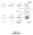
- Figure 1a shows a typical MIMO data communications system 100.
- a data source 102 provides data (comprising information bits or symbols) to a channel encoder 104.
- the channel encoder typically comprises a convolutional coder such as a recursive systematic convolutional (RSC) encoder, or a stronger so-called turbo encoder (which includes an interleaver). More bits are output than are input, and typically the rate is one half or one third.
- RSC recursive systematic convolutional
- turbo encoder which includes an interleaver
- More bits are output than are input, and typically the rate is one half or one third.
- the channel encoder 104 is followed by a channel interleaver 106 and, in the illustrated example, a space-time encoder 108.
- the space-time encoder 108 encodes an incoming symbol or symbols as a plurality of code symbols, which are mapped to complex modulation symbols such as QPSK (quadrature phase shift keying), M-QAM (M-ary quadrature amplitude modulation) for simultaneous transmission from each of a plurality of transmit antennas 110.
- QPSK quadrature phase shift keying
- M-QAM M-ary quadrature amplitude modulation
- Space-time encoding may be described in terms of an encoding machine, described by a coding matrix, which operates on the data to provide spatial and temporal transmit diversity or multiplexing; this is typically followed by a modulator to provide coded symbols for transmission.
- Space-frequency encoding may additionally (or alternatively) be employed.
- incoming symbols and processed versions (such as symbols which are phase-shifted and scaled according to the Space-Time code algorithm) are distributed into a grid having space and time and/or frequency coordinates, for increased diversity.
- space-frequency coding the separate frequency channels may be modulated onto OFDM (orthogonal frequency division multiplexed) carriers, a cyclic prefix generally being added to each transmitted symbol to mitigate the effects of channel dispersion.
- the encoded transmitted signals propagate through MIMO channel 112 to receive antennas 114, which provide a plurality of inputs to a space-time (and/or frequency) decoder 116. This has the task of removing the effect of the encoder 108.
- the output of the decoder 116 comprises a plurality of signal streams, one for each transmit antenna, each carrying so-called soft or likelihood data on the probability of a transmitted symbol having a particular value. This data is provided to a channel de-interleaver 118 which reverses the effect of channel interleaver 106, and then to a channel decoder 120, such as a Viterbi decoder, which decodes the convolutional code.
- channel decoder 120 is a SISO (soft-in soft-out) decoder, that is receiving symbol (or bit) likelihood data and providing similar likelihood data as an output rather than, say, data on which a hard decision has been made.
- SISO soft-in soft-out
- the output of channel decoder 120 is provided to a data sink 122, for further processing of the data in any desired manner.
- turbo or iterative decoding in which a soft output from channel decoder 120 is provided to a channel interleaver 124, corresponding to channel interleaver 106, which in turn provides soft (likelihood) data to decoder 116 for iterative space-time (and/or frequency) and channel decoding.
- channel decoder 120 provides complete transmitted symbols to decoder 116, that is for example including error check bits.
- MIMO systems may encounter different types of channels.
- the capacity of a MIMO system is not only dependent on SNR but also dependent on the type of channel.
- Two types of channel are Line-Of-Sight (LOS) and multipath-rich channels (see Da-Shan Shiu; Foschini, G.J.; Gans, M.J.; Kahn, J.M., Fading correlation and its effect on the capacity of multielement antenna systems, Communications, IEEE Transactions on, Vol.48, Iss.3, Mar 2000, Pages:502-513).
- MIMO Multiple Access
- space-time diversity techniques deliver higher data rates with LOS channels
- multiplexing techniques perform better with multipath-rich channels (see Parker, S., Sandell, M., Lee, M., The performance of space-time codes in office environments, Vehicular Technology Conference, 2003. VTC 2003-Spring. The 57th IEEE Semiannual, Volume: 1 , 22-25 April 2003, Pages:741 - 745).
- WO '646 describes a multiple-antenna processing scheme in which transmit power is allocated to antennas according to one of a selection of techniques including a water-filling transmission scheme, a selective channel inversion transmission scheme, a uniform transmission scheme, a principal eigenmode beam-forming transmission scheme and a beam-steering transmission scheme.
- EP '001 describes a MIMO OFDM system in which, broadly speaking, the arrangement of data on OFDM sub carriers uses either time diversity or spatial diversity based upon one of three criteria relating to the channel condition with the aim of maintaining a defined minimum threshold quality of service (QoS), in '001 defined as the number of times that the same packet can be re-transmitted.
- QoS quality of service
- the channel matrix H namely the ratio of the largest and smallest eigenvalues of the MIMO channel matrix H.
- This document also discloses the selection of a modulation scheme for each sub carrier based upon the estimated carrier-to-inference or signal-to-noise ratio.
- the Abe et al. paper describes a hybrid MIMO system which selectively employs either spatial multiplexing or transmit diversity (selection diversity in which the whole transmit power is provided to the antenna which provides the largest received SNR and in which spatial correlation between data streams of the MIMO channel matrix is used as a metric.
- a feedback channel from the receiver to the transmitter allows transmission mode commands defining the transmission scheme and symbol constellation size to be provided from the receiver to the transmitter; a similar arrangement may be implemented in the generalised system of Figure 1 by means of a transmitter 126 and a receiver 128, which need only have a low bandwidth.
- an adaptive MIMO communications system comprising a MIMO transmitter and a MIMO receiver and having a feedback path from said receiver to said transmitter, said MIMO transmitter including a receiver to receive a feedback signal from said receiver sent via said feedback path and a controller responsive to said feedback signal to configure a MIMO transmission from said transmitter to said receiver; said MIMO receiver being configured to receive said MIMO transmission; and wherein said MIMO receiver includes a decision module, said decision module having a power indicating input to input a signal indicating a desired receiver power consumption, and an output for sending a MIMO configuration signal to said MIMO transmitter, said decision module being configured to determine a MIMO transmission configuration responsive to said power indicating input and to output a MIMO configuration signal for feedback to said transmitter to configure said transmitter in accordance with said determination.
- a battery powered device may include a battery monitor and/or user-definable power mode defining an approximate power consumption.
- power consumption constraint data which may be provided in real time from a battery monitor, allows the MIMO scheme and/or constellation and/or data rate to be modified, for example to reduce the data rate or use a scheme with a lower decoding complexity to reduce the power consumption as the battery discharges and nears the end of its capacity.
- the invention further provides an adaptive MIMO communications system comprising a MIMO transmitter and a MIMO receiver and having a feedback path from said receiver to said transmitter, said MIMO transmitter including a receiver to receive a feedback signal from said receiver sent via said feedback path and a controller responsive to said feedback signal to configure a MIMO transmission from said transmitter to said receiver; said MIMO receiver being configured to receive said MIMO transmission; and wherein said MIMO receiver includes a communications quality of service (QoS) measuring system having measured QoS signal output, and a decision module, said decision module having a first, measured QoS input and a second input to input a signal indicating a desired QoS, and an output to output a MIMO configuration signal, and wherein said decision module is configured to input a said desired QoS signal, determine a first MIMO transmission configuration responsive to said desired QoS signal, output a first MIMO configuration signal for feedback to said transmitter to configure said transmitter in accordance with said determination, input a said measured QoS signal, determine a second MIMO transmission
- the second MIMO transmission configuration may be modified to take account of the actual, measured quality of service, for example as defined by a block error rate, optionally averaged over time.
- the choice of MIMO transmission configuration indicated by a lookup table may be followed only if the quality of service is within a desired range, and if not the transmission configuration may be modified.
- the desired quality of service may be subordinate to other requirements, in particular a power requirement, for example to allow a user to trade off quality against battery life.
- the transmitter may include a data compression or other input signal pre-processing module such as an audio and/or video compression module.
- the MIMO configuration signal generated by the receiver may indicate that a reduced data rate is to be employed.
- this may be implemented, for example, by increasing the compression ratio and/or decreasing the audio or video data capture resolution.
- the desired quality of service signal may comprise a signal indicating a type of data to be transmitted, for example one of a number of categories such as streamed media (audio and/or video), email/web traffic, and the like. Each of these categories of data may be associated with a minimum acceptable quality of service level.
- the decision module may also take into account other factors, in particular a history of MIMO transmission configurations and/or a channel metric.
- a MIMO transmission configuration includes one or more of a MIMO transmission scheme and/or algorithm, a constellation size, and a data rate.
- channel metrics which may be employed including signal-to-noise ratio, power-delay profile, capacity, inter-channel correlation as used by Abe et al., ibid, hereby incorporated by reference, and/or a measure of channel condition as described, for example, in EP 1185001 at paragraph 37 (hereby incorporated by reference).
- the channel metric computation may comprise an average over time and the time over which the average is taken may then be varied according to the type of MIMO channel.
- the MIMO channel is expected to change only slowly whereas outdoors the MIMO channel will change at a speed dependent upon the relative speed of motion of the transmitter and receiver, for example slowly for a pedestrian and fast for an in-car user.
- An indication of channel type may be provided to the channel metric computation module either, for example, from a pre-configuration in hardware, or from a channel estimation module within the receiver, or from the decision module, for example by observing the average block error rate.
- the decision module incorporates a lookup table for determining a MIMO transmission scheme and constellation (and optionally data rate) responsive to parameters such as a power constraint and a data type, and also a decision modifier to optionally modify data read from the lookup table responsive to, say, a measured quality of service such as a block error rate.
- a desired and/or measured quality of service may provide an input to the lookup table and the data read from this table may then be modified by, say, a power constraint signal in order to allow an overriding power constraint to take priority over one or more other parameters.
- a power constraint signal in order to allow an overriding power constraint to take priority over one or more other parameters.
- the receiver is configured to share computational resources between a channel metric computation module or component and a MIMO decoding module or component. This may be achieved by performing a decomposition of the MIMO channel matrix as estimated at the receiver, for example a QR or SVD decomposition, to provide intermediate data which is usable for both a channel metric computation and for decoding a received MIMO signal. Additionally or alternatively in these or other embodiments the speed/economy of the receiver may be improved by, in effect, combining the MIMO channel matrix estimation procedure with the MIMO channel matrix estimate decomposition.
- channel estimation may be performed by transmitting a training sequence from each transmit antenna in turn (listening on all the receive antennas), or by simultaneously transmitting substantially orthogonal training sequences from all the transmit antennas.
- the MIMO channel estimate matrix may be constructed column by column, and it has been appreciated that QR and other matrix decompositions may also be performed column-by-column, in step with construction of the channel estimate matrix.
- the classical Gram-Schmidt algorithm used for QR decomposition generates one column of both Q and R per algorithm step (see, for example, Golub G.H., Van Loan C.F., Matrix computations 3rd ed., Johns Hopkins Univ. Pr.
- an adaptive MIMO communications system comprising a MIMO transmitter and a MIMO receiver and having a feedback path from said receiver to said transmitter, said MIMO transmitter including a receiver to receive a feedback signal from said receiver sent via said feedback path and a controller responsive to said feedback signal to configure a MIMO transmission from said transmitter to said receiver; said MIMO receiver being configured to receive said MIMO transmission; and wherein said MIMO receiver includes a channel metric computation module having a channel metric output and a decision module, said decision module having a channel metric input and an output for sending a MIMO configuration signal to said MIMO transmitter, said decision module being configured to determine a MIMO transmission configuration responsive to said channel metric input and to output a MIMO configuration signal for feedback to said transmitter to configure said transmitter in accordance with said determination; wherein said receiver is further configured to estimate a MIMO channel response matrix for decoding a received signal and for computing a said channel metric, and to determine a decomposition of said channel response matrix, for computing a said channel
- the invention also provides an adaptive MIMO communications system comprising a MIMO transmitter and a MIMO receiver and having a feedback path from said receiver to said transmitter, said MIMO transmitter including a receiver to receive a feedback signal from said receiver sent via said feedback path and a controller responsive to said feedback signal to configure a MIMO transmission from said transmitter to said receiver; said MIMO receiver being configured to receive said MIMO transmission; and wherein said MIMO receiver includes channel metric computation module having a channel metric output and a decision module, said decision module having a channel metric input and an output for sending a MIMO configuration signal to said MIMO transmitter, said decision module being configured to determine a MIMO transmission configuration responsive to said channel metric input and to output a MIMO configuration signal for feedback to said transmitter to configure said transmitter in accordance with said determination; wherein said receiver is further configured to estimate a MIMO channel response matrix for decoding a received signal and for computing a said channel metric, and to determine a decomposition of said channel response matrix, for computing a said channel metric and for de
- the invention provides firstly, a transmitter, and secondly, a receiver, as described above.
- the invention also provides a MIMO receiver for receiving a MIMO transmission, the receiver comprising: a MIMO channel matrix estimator to estimate a MIMO channel response matrix for decoding a received signal; and a matrix decomposition module to determine a decomposition of said channel response matrix for decoding a received signal; and wherein said receiver is configured to estimate said channel response in parallel with said channel matrix response decomposition determination.
- the invention also provides a method of configuring an adaptive MIMO communications system comprising a MIMO transmitter and a MIMO receiver and having a feedback path from said receiver to said transmitter, said MIMO transmitter including a receiver to receive a feedback signal from said receiver sent via said feedback path and a controller responsive to said feedback signal to configure a MIMO transmission from said transmitter to said receiver, said MIMO receiver being configured to receive said MIMO transmission, the method comprising: inputting a signal indicating a desired receiver power consumption; determining a MIMO transmission configuration responsive to said power indicating input; and outputting a MIMO configuration signal for feedback to said transmitter to configure said transmitter in accordance with said determination.
- the invention further provides a method of configuring an adaptive MIMO communications system comprising a MIMO transmitter and a MIMO receiver and having a feedback path from said receiver to said transmitter, said MIMO transmitter including a receiver to receive a feedback signal from said receiver sent via said feedback path and a controller responsive to said feedback signal to configure a MIMO transmission from said transmitter to said receiver, said MIMO receiver being configured to receive said MIMO transmission, the method comprising: inputting a desired communications quality of service (QoS) signal; determining a first MIMO transmission configuration responsive to said desired QoS signal; outputting said first MIMO configuration signal for feedback to said transmitter to configure said transmitter in accordance with said determination; measuring a communications quality of service (QoS); determining a second MIMO transmission configuration responsive to said measured QoS; and outputting a second MIMO configuration signal for feedback to said transmitter to configure said transmitter in accordance with said second determination.
- QoS communications quality of service
- the above-described systems, transmitters, receivers and methods may be implemented using processor control code, optionally provided on a data carrier such as a disk, CD-or DVD-ROM, programmed memory such as read-only memory (Firmware), or on a data carrier such as optical or electrical signal carrier.
- a data carrier such as a disk, CD-or DVD-ROM, programmed memory such as read-only memory (Firmware), or on a data carrier such as optical or electrical signal carrier.
- transmitters, receivers and methods will be implemented on a DSP (Digital Signal Processor), ASIC (Application Specific Integrated Circuit) and/or FPGA (Field Programmable Gate Array).
- code (and data) to implement embodiments of the invention may comprise code in a conventional programming language such as C, or microcode.
- code to implement embodiments of the invention may alternatively comprise code for setting up or controlling an ASIC or FPGA, or code for a hardware description language such as Verilog (Trade Mark), VHDL (Very high speed integrated circuit Hardware Description Language) or SystemC.
- Verilog Trade Mark
- VHDL Very high speed integrated circuit Hardware Description Language
- SystemC SystemC
- an intelligent adaptive MIMO system in which decisions on the MIMO encoding and decoding schemes are based upon a range of parameters, as well as an estimated channel metric and the signal-to-noise ratio (or SNR range) also including information from layers above the physical layer such as quality of service requirements and power constraints, further taking into account actual performance indications.
- embodiments of the adaptive system aim to provide optimum physical layer throughput using a feedback channel from the receiver to the transmitter of a MIMO transceiver system.
- other parameters such as the modulation type of constellation size may also be varied.
- the upper - or application - layer information may comprise restrictions on a required BLER (block error rate), optionally varied according to the type of data to be sent from the transmitter to the receiver, and/or a CRC (cyclic redundancy check) performance.
- BLER block error rate
- CRC cyclic redundancy check
- the power consumption constraints which may be employed, for example in the case of portable devices, may be provided in real time from battery management components.
- Other parameters input to the decision making process may comprise the signal-to-noise ratio or carrier-to-interference ratio.
- the physical layer information may also comprise a computed channel metric, for example constructed from information relating to the channel statistics such as SNR, the power delay profile, the channel capacity, the degree of correlation between MIMO channels, and the channel conditions (for example determined by means of Singular Value Decomposition or a similar technique), and optionally any other available information.
- a computed channel metric for example constructed from information relating to the channel statistics such as SNR, the power delay profile, the channel capacity, the degree of correlation between MIMO channels, and the channel conditions (for example determined by means of Singular Value Decomposition or a similar technique), and optionally any other available information.
- Figure 1b shows a typical single-scheme MIMO decoding architecture 150 comprising a plurality of receive antennas 152 providing received signals to a MIMO decoder 154 and to a MIMO channel matrix estimator 156.
- Channel estimator 156 provides a first output 158a to MIMO decoder 154 comprising an estimate of the MIMO channel matrix, and a second output 158b to the MIMO decoder 154 comprising a signal-to-noise ratio estimate, which is the operating SNR.
- the MIMO decoder 154 provides a plurality of symbol outputs 160, one for each transmit antenna, comprising estimates of the symbols sent from each transmit antenna, and these symbols are converted back into a bit stream by a symbol-to-bit converter 162 which provides a serial data output 164. MIMO decoder 154 also provides a noise variance estimate (for each symbol) output 161 to the symbol-to-bit decoder. The noise variance information is used by the symbol-to-bit decoder in order to produce soft-value outputs. It will be recognised that apart from antenna front ends and down conversion circuitry (not shown in Figure 1b) generally the received signals will be digitised at an early stage and the architecture illustrated in Figure 1b will therefore comprise a software architecture.
- FIG. 2 shows an example of an architecture of an intelligent adaptive MIMO receiver 200 embodying aspects of the present invention; for completeness a corresponding MIMO transmitter 280 is also shown.
- the receiver 200 of Figure 2 comprises six main sections: a hybrid MIMO decoder system 202, similar to the MIMO decoder of Figure 1b but reconfigurable such that it can be controlled to decode different MIMO algorithms and constellation sizes as needed; a MIMO scheme selection module 204; a data post-processing module 206; a channel condition estimation module 208; a decision module 210; and a feedback system 212.
- the MIMO decoder system comprises a plurality of receiver antennas 214 which provide a plurality of received signals to a hybrid MIMO decoder 216 and also to a MIMO scheme and constellation (Q) selector 218 of scheme selection module 204 and to a MIMO channel estimator 220 of channel condition estimation module 208.
- the channel estimator 220 provides an estimate of a MIMO channel matrix, H, and an SNR estimate of respective outputs 220a, b.
- the scheme and constellation selector 218 receives and decodes scheme and constellation selection information sent from the MIMO transmitter 280 and provides respective MIMO scheme identification and constellation/Q identification data outputs 218a, b.
- a packetised data transmission scheme is employed and a packet header information may then include this MIMO scheme and constellation identification data; this may be encoded using a pre-determined default encoding scheme, preferably one which is relatively straightforward to decode.
- information defining the active MIMO scheme and constellation may be transmitted during a special (pre-arranged) packet transmission, or even at the trailing end of a previously transmitted packet; the information signalling the hybrid MIMO decoder 216 to change scheme should, however, arrive before the actual data to be decoded.
- the hybrid MIMO decoder reconfiguration may take place at the same time as a channel estimation process.
- MIMO transmission schemes examples include, but are not limited to, Alamouti (a simple space-time code which provides a transmit diversity of two), vertical BLAST (Bell labs Layered Space Time) decoding and Bell labs Layered Time, and other techniques, such as those described in the following references: V. Tarokh, H. Jafarkhani and A. R. Calderbank, "Space-time block codes from orthogonal designs," IEEE Trans. Info. Theory., vol. 45, pp. 1456-1467, July 1999; B. Hassibi and B. Hochwald, "High-rate codes that are linear in space and time," IEEE Trans. Info. Theory., vol. 48, pp. 1804-1824, Jul. 2002); also see G. J.
- Foschini "Layered space-time architecture for wireless communication in a fading environment when using multi-element antennas," Bell Labs. Tech. J., vol. 1, no. 2, pp. 41-59, 1996 for BLAST, and S. M. Alamouti, "A simple transmitter diversity scheme for wireless communications," IEEE J. Sel. Area Comm., pp. 1451-1458, Oct. 1998 for Alamouti.
- Other MIMO decoding schemes are described in the applicant's co-pending UK patent applications numbers 0219056.9 filed 15 August 2002, 0227770.5 filed on 28 November 2002, 0323074.5 filed on 2 October 2003, 0323208.9 filed on 3 October 2003, 0323211.3 filed on 3 October 2003, and 0329230.7 filed on 17 December 2003.
- Modulation schemes/constellations which may be employed include, but are not limited to, M-PSK and M-QAM.
- M-PSK M-PSK
- M-QAM M-QAM
- the hybrid MIMO decoder 216 accepts the MIMO scheme and constellation information from outputs 218a, b and the channel estimate and signal-to-noise ratio information from outputs 220a, b as well as one signal from each receive antenna and provides a plurality of symbol outputs 222, one corresponding to each transmit antenna, as well as a noise variance for each symbol (222) output 224, these being provided, together with the modulation/constellation type information from output 218b, to a symbol-to-bit converter 226 which provides an output bit stream 228 comprising an estimate of a bit stream provided to MIMO transmitter 280.
- This bit stream is provided to the data post-processing module 206 which may include a variety of other processing 230, for example channel decoding using, say, a Viterbi decoder, and a CRC check 232.
- processing 230 for example channel decoding using, say, a Viterbi decoder, and a CRC check 232.
- CRC check 232 a CRC check 232.
- the data post-processing module 206 provides a data output 234 to higher level modules, for example medium-access control (MAC) layer modules and application layer modules such an audio and/or video decoder.
- MAC medium-access control
- Data post-processing module 206 also provides a channel statistics data output 236 comprising statistical data relating to an actual (measured) channel performance, for example comprising an instantaneous or average block error rate (BLER). This measured statistical information is provided to the decision module 210.
- BLER block error rate
- this also includes a channel metric computation module 238 having an input from the MIMO channel estimate output 220a of channel estimator 220 and providing a channel metric data output 240 to decision module 210.
- the channel metric computation module 238 may operate in any conventional manner to compute a channel metric based upon, for example, QR factorisation or SVD (singular value decomposition).
- QR factorisation or SVD singular value decomposition
- Some channel metric computation techniques are described in the prior art documents to which reference has already been made (in particular EP 1185001 and Abe et al.); alternatively where, for example SVD is employed then a channel condition metric may be determined from the ratio of the largest to the smallest singular value. Additionally or alternatively the smallest singular value and/or diagonal element may be employed as an indicator of the applicability or robustness of a particular MIMO transmission scheme.
- the channel condition may be computed as an average over time and the channel metric computation module 238 may be provided with a channel type data input 242 indicative of the type of MIMO channel, for example indoor or outdoor, and this information may be used to determine over what period to average. For example for an indoor environment it may be appropriate to average over a period of from 1 to 10 seconds whereas for an outdoor environment it may be appropriate to average over a period of less than 1 second or possibly less than 0.1 second. Additionally or alternatively the channel metric computation module may determine a channel metric using one or more of channel statistics such as the power delay profile, the channel capacity, and the correlation between the MIMO channels. As previously mentioned generally channel estimator 220 will determine a channel estimate by making use of a known training sequence.
- the channel estimator and/or channel metric computation module can be assisted by being provided with information relating to the channel characteristics or type, which can assist in adapting to an optimum sampling rate and which can improve tracking performance and, more generally, provide improved estimates of the channel/channel statistics.
- the lookup table 244 is configured to receive a number of parameters indexing entries within the table and to provide a pair of outputs 244a, b identifying a MIMO transmission scheme and constellation size/type respectively.
- the input parameters in the illustrated embodiment, comprise a power constraint input for index 244c, a data type input or index 244d, a channel metric input or index 240, and an average SNR input or index 244e. Each of these input parameters effectively acts as a dimension of the lookup table 244, a set of input parameters identifying a pre-determined MIMO scheme and constellation for output.
- the data in lookup table 244 will depend upon the particular implementation of the MIMO system, the power constraints, the required performance, and the like.
- data for the lookup table may readily be determined by routine experiment, for example by measuring the power consumption of a particular MIMO decoding scheme and by experimentally determining the performance of particular combinations of MIMO schemes and constellation sizes/types under a range of conditions (channel type, data type, average SNR), when subject to a range of minimum quality of service requirements.
- the results of such routine experiments may then be examined to determine, for a particular set of input parameters, a third MIMO scheme and constellation size/type and this data can then be permanently (or upgradably) stored in the lookup table to 244 which may comprise, for example, ROM or Flash RAM.
- the lookup table may store data relating to the expected performance of a range of combinations of MIMO schemes and constellation sizes/types (which the hybrid MIMO detector can support) and also data relating the expected power consumption for each of these schemes/constellation types, for a subset of or for all possible input parameter values.
- the lookup table is then effectively configured to respond to a query from the decision logic component 246 comprising, for example, a channel metric, SNR, data type, and/or power constraint, by outputting data identifying the optimal MIMO transmission scheme and constellation type/size to employ.
- a simple scheme such as an Alamouti scheme may be employed whereas when more power is available a BLAST-type scheme using a high-performance high-complexity MIMO decoder may be employed.
- the outputs 244a, b from lookup table 244 may be taken to define the MIMO scheme and constellations to be employed by the transmitter 280.
- the decision module 210 incorporates a decision logic component 246 which is able to modify the supposed optimal scheme/constellation output from the lookup table, in particular to provide feedback based upon actual measured performance of a selected scheme/constellation.
- This information is provided to the decision logic 246 from the post-processing module 206, for example via output 236 from CRC check unit 232 (although since the output of a CRC check is generally simply a logic value, true or false - pass or fail, this may need to be converted to a statistic).
- the decision logic 246 facilitates modification of the outputs from lookup table 244 in many ways. For example if the selected scheme/constellation provides a block error rate within a desired range then the scheme/constellation may be left unchanged, otherwise it may be modified. Additionally or alternatively the lookup table 244 may suggest a power hungry MIMO decoding scheme but other information may indicate, for example, that a battery has only a few minutes of life left, in which case the choice can be modified to a simpler scheme, requiring less processing power to decode, and hence extending the available battery life. Alternatively if the measured block error rate (or other statistic) implies that the quality of service is higher than necessary the scheme/constellation may be modified to deliver a higher data throughput at a lower, but still acceptable quality of service.
- decision logic component 246 has or can derive knowledge of the channel type (for example how fast it changes and whether it is an indoor or an outdoor environment) and of the data type (for example non-time critical data for web browsing, time-critical data for video transmission, required transmission quality for video, and the like), for example in the form of BLER requirements.
- the average SNR estimator 248 may also provide an input to lookup table 244.
- the SNR estimator 248 receives estimated SNR data from channel estimator 220 and calculates a running or windowed average of this, and is preferably re-settable by an output 246a from decision logic component 246, for example when the MIMO scheme/constellation changes or at other times when the channel characteristics may change.
- the decision logic component 246 of decision module 210 provides an output 246b to feedback path module 212 comprising data identifying a MIMO scheme and constellation size/type.
- This information is sent back to MIMO transmitter 280 by any convenient communications method, which may or may not comprise wireless communications.
- the scheme/constellation data is provided to a buffer 248 and thence to a transmit antenna 250 which sends the data back to a receive antenna 282 coupled to MIMO transmitter 280 so that the MIMO transmitter can receive the scheme/constellation command data and configure the transmissions accordingly.
- MIMO transmitter 280 is configured to transmit video data compressed by a video data compression module 284.
- the feedback path from the receiver 200 to the transmitter 280 need only be relatively low bandwidth as the information to be sent, that is the receiver's estimate of the optimal scheme and constellation type/size for recurrent period of time, may be defined by just a few bits.
- a single bit may be employed for scheme selection for a hybrid decoder with two schemes, such as Alamouti and BLAST (or similar techniques), and two bits may be employed to define a constellation size if choosing between four types, for example BPSK (binary phase shift keying), QPSK (quadrature PSK), 16-QAM, and 64-QAM.
- this information may be included in headers sent inside acknowledgement packets (as sending such acknowledgement packets is normal for applications with a defined quality of service requirement).
- buffer 248 may comprise a header transmit queue.
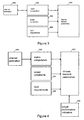
- Figures 3 to 5 illustrate generic architectures for intelligent adaptive MIMO systems as described in detail above with reference to Figure 2.
- a transmit parameter selection/decision module 300 receives inputs from a metric computation module 302, a power constraint determining module 304, and a quality of service requirements module 306, the metric computation module 302 in turn receiving an input from a channel estimation module 308.
- the architecture of Figure 4 is similar except that the selection/decision module 400 also receives an input from one or more actual performance indicators 402; the arrangement of Figure 5 has a selection/decision module 500 which further receives or has knowledge of a history of chosen transmit parameters 502 (scheme and/or constellation size/type).
- the receiver signal processing resources can be shared to increase the processing and/or reduce power consumption (or possibly silicon area). This based upon a recognition that, firstly, decomposition of the MIMO channel estimate matrix can be used as a precursor to both determining a channel condition or metric and decoding received data, and secondly that decomposition of the channel estimate matrix can proceed in parallel with a determination of the channel estimation matrix itself.
- MIMO decoding generally relies upon some form of factorisation of the matrix channel estimate, such as QR factorisation or SVD factorisation, to estimate the transmitted symbols (see, for example, Wubben D., Bohnke R., Rinas J., Kuhn V., Kammeyer K.D., Efficient algorithm for decoding layered space-time codes, IEEE Electronics Letters, Vol. 37, No. 22, Oct. 2001).
- the channel metric computation may also rely upon or be simplified by a decomposition of the matrix channel estimate and thus by configuring the receiver so that there is a common initial stage of decomposition or factorisation of the MIMO channel estimate matrix the computational load in the receiver may be reduced.
- a channel condition may be determined by taking the ratio of highest to lowest singular values of a singular value decomposition.
- the SVD may be determined via a QR factorisation (see, for example, Golub G.H., Van Loan C.F., Matrix computations 3rd ed., Johns Hopkins Univ. Pr. Baltimore, Md, 1996, in particular paragraph 3.54, algorithm 3.5.1, hereby incorporated by reference), or alternatively QR factorisation may be used to determine the channel conditions directly.
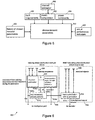
- Figure 6 shows a portion of a MIMO receiver 600 which schematically illustrates this procedure, showing how resources may be shared between an intelligent or adaptive part of the receiver, for example using channel condition information, and a decoding part of the receiver, in the illustrative example employing a back substitution-algorithm.
- the two dashed boxes 602, 604 of Figure 6 indicate a training phase of the receiver's operation and a decoding phase of the receiver's operation respectively; physically the two sets of receive antennas 606 are the same.
- the receiver receives training sequences, for example at the start of a packet, which are provided to a channel estimation/decomposition module 608.
- This module performs a channel estimation and matrix decomposition, preferably in parallel as described further below, determining a QR factorisation of the MIMO channel estimate matrix and providing Q and R matrix outputs 608a, b, an estimated signal-to-noise ratio output 608c, and a channel condition output 608d, for example based upon highest to lowest singular value ratio.
- the Q and R values may be pre-processed or transformed by a precalculation component 610 in order to simplify and/or improve the reliability of a subsequent back-substitution procedure.
- values inside the matrix R which are very close or equal to 0 can cause problems when performing back-substitution 612, effectively because they are used as divisors in division operations (for a formulation of back-substitution algorithm - see, for example, Golub G.H., Van Loan C.F., Matrix computations 3rd ed., Johns Hopkins Univ. Pr. Baltimore, Md, 1996, in particular section 3.1.2). This can result in erroneously estimating the transmitted symbols and can also result in arithmetic overflows during the division operations of the decoding hardware, and these values may therefore be adjusted. Any necessary pre-calculations may be performed after or during (as described further below) channel estimation at the start of a block.
- the precalculation step 610 can also function in-place of the back-substitution demultiplexing algorithm 612 as described, for example, in Golub et al. section 5.7.1.
- the training phase 602 is generally performed no more frequently than once for each block of received symbols processed but the decoding is performed for each set of received data symbols.
- figure 8 shows a block of symbols according to the IEEE 802.11a standard IEEE Std 802.11a-1999 [ISO/IEC 8802-11:1999/Amd 1:2000(E)] (Supplement to IEEE Std 802.11, 1999 Edition) Part 11: Wireless LAN Medium Access Control (MAC) and Physical Layer (PHY) specifications: High-speed Physical Layer in the 5 GHz Band (in particular a PPDU frame format).
- the PLCP Preamble and SIGNAL OFDM symbols are followed (in time) by the data part that carries several OFDM symbols carrying the data symbols which are decoded by the receiver (decoding phase).
- the QR decomposition, pre-processed as necessary is provided to, for example, a back-substitution module 612 with quantisation to provide a demultiplexed signal stream 614 for further processing.
- a received signal vector y Q ⁇ R ⁇ c
- c is a transmitted signal vector
- Q the inverse from definition (of the QR decomposition) and multiplied by y and because R is an upper triangular matrix
- the symbol c can be determined element by element, starting by determining C n from Q T y n and working backwards, for each c-value in turn quantising the value to the closest constellation point.
- the MIMO decoder can use a straightforward back-substitution method with quantisation for estimating each symbol in the block, whilst simplifying the channel metric computation process.
- the QR or other decomposition may be performed in parallel with the channel estimation procedure.
- the channel estimation may be performed column-by-column and the QR decomposition procedure may also allow decomposition on a column-by-column basis.
- mGS modified-Gram Schmidt
- Steps 1 and 2 use the first column of H
- steps 3 and 4 use the second
- 5 and 6 use the third and steps 7 and 8 use the fourth column of H. It is therefore possible to parallelize the channel estimation process with those first steps of the modified-Gram Schmidt (mGS) algorithm.
- the estimation and decomposition steps are:
- channel estimation may in fact comprise a single, unified procedure.
- determination of the channel condition estimation metric may comprise a different component or module of the architecture and this component may operate, for example, during and in parallel with the back-substitution procedure.
- Figure 7a shows a receiver 700 incorporating an adaptive MIMO decoder and configured to implement the above described techniques.
- Receiver 700 comprises one or more receive antennas 702a, b (of which two are shown in the illustrated embodiment) each coupled to a respective RF front end 704a, b, for example similar to the RF front end of Figure 2a, and thence to a respective analogue-to-digital converter 706a,b and to a digital signal processor (DSP) 708.
- DSP 708 will typically include one or more processors 708a (for example, for a parallel implementation of filter 414) and some working memory 708b.
- the DSP 708 has a data output 710 and an address, data and control bus 712 to couple the DSP to permanent program memory 714 such as flash RAM or ROM.
- Permanent program memory 714 stores code and optionally data structures or data structure definitions for DSP 708.
- program memory 714 includes MIMO scheme and constellation selection code comprising SNR averaging, channel metric computation control, lookup table interface and MIMO/constellation decision components to, when running on DSP 708, implement corresponding functions as described above.
- Program memory 714 also includes column-by-column MIMO channel estimation code 714b to provide a MIMO channel estimate H, column-by-column MIMO channel matrix decomposition code 714c, (optional precalculation and) back-substitution code 714d, channel metric computation code 714e, a lookup table 714f comprising data for selecting a MIMO scheme and constellation size/type, MIMO scheme and constellation size/type control data reception code 714g, and optionally de-interleaver code 714h, interleaver code 714i, and channel decoder code 714j. Examples of suitable code 714e are well known to those skilled in the art.
- the code in permanent program memory 714 may be provided on a carrier such as an optical or electrical signal carrier or, as illustrated in
- the data output 710 from DSP 708 is provided to further data processing elements of receiver 700 (not shown in Figure 7) as desired. These may a baseband data processor for implementing higher level protocols.
- the receiver front-end will generally be implemented in hardware whilst the receiver processing will usually be implemented at least partially in software, although one or more ASICs and/or FPGAs may also be employed.
- ASICs and/or FPGAs may also be employed.
- All the functions of the receiver could be performed in hardware and that the exact point at which the signal is digitised in a software radio will generally depend upon a cost/complexity/power consumption trade-off.
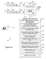
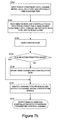
- Figure 7b shows an outline flow diagram illustrating the operation of the MIMO scheme and constellation selection code 714a of the receiver 700 of Figure 7a.
- the code receives power constraint data, channel metric data, data type data and optionally time averaged SNR data and, at step S722, uses these data to read data identifying a MIMO scheme and constellation from lookup table 714F.
- the code reads the average block error rate and, and at step S726, determines whether or not this is within a permitted range (S726), if not modifying the MIMO scheme and/or constellation recommended by the lookup table (S728).
- the scheme/constellation selection code identifies a channel type from the block error rate and outputs channel-type data to the channel metric computation module 714e (which may modify the MIMO scheme/constellation indicated by the lookup table data). Then, at step S732, the MIMO scheme and constellation data are output a feedback (transmitter control) channel for the transmitter to implement.
- the receiver is instructed, as previously described, by transmitting scheme and constellation selection data to the receiver for interpretation and implementation by control data reception code 714g.
- Embodiments of the above-described techniques facilitate better adaptation of a MIMO communications system to the channel conditions and other constraints, in particular relating to power consumption.
- a space-time coding scheme such as Alamouti employs diversity to decrease the bit error rate and is thus robust to afford channel conditions and noise but typically has a maximum rate (compared with a single-in-out system) of unity
- a spatial multiplexing scheme such as BLAST potentially offers a maximum rate equal to the number of transmit antennas but which can drop significantly (even below unity) for ill-conditioned channels and/or low SNRs.
- channel coding rate i.e., referring to elements of Figure 1, encoder 104, decoder 120
- this is contemplated in embodiments/aspects of the invention.
- channel coding rate/algorithm may effectively be read/understood in addition to and/or in place of references to constellation or a constellation parameter.
- Embodiments of the above-described adaptive MIMO communications system can provide a minimum throughput guarantee for applications requiring operation at or below a given error rate, providing the channel and SNR permit (therefore satisfying quality of service requirement).
- the described techniques are also helpful for adapting the power consumption of the receiver, for example by trading throughput and complexity.
- embodiments of the system can effectively ensure a performance floor over an envelope of channel metric/SNR/QoS requirements.
- computational resources in particular relating to MIMO channel matrix decomposition, can be re-used in order to reduce hardware complexity and/or power consumption and/or optionally increase speed.
- Embodiments of the above-described techniques have applications in a wide range of MIMO communications systems including base stations, access points, and mobile terminals/devices.
- MIMO schemes for use in the adaptive communications process may be selected from very simple schemes such as Alamouti to complex space-time and/or frequency MIMO schemes such as BLAST or sphere decoding.
- embodiments of the invention facilitate improved or at least a more consistent level of performance and/or, depending upon the conditions and parameters, increased data rates and/or, in particular embodiments, more efficient use of hardware resources.
Abstract
Description
- This invention is generally concerned with apparatus, methods and processor control code for MIMO (multiple-input multiple-output) communications systems.
- An underlying idea in MIMO systems is space-time signal processing, which effectively takes advantage of the separatability of the spatial channels between the multiple transmit and multiple receive antennas or the MIMO channels to provide higher data rates without a concomitant increase in spectral usage or, alternatively, increased robustness and a lower error rate. Broadly speaking coding a signal in space or/and time (spatial, time and space-time diversity) increases robustness by effectively providing numerous versions of a signal whilst multiplexing in space (spatial multiplexing) effectively increases the available data rate. In a fixed configuration MIMO system a choice must be made as to this trade-off between spatial-multiplexing and space-time-diversity although one of the major advantages of MIMO systems is generally seen as their ability to provide an increased data rate transmission.
- The current generation of WLAN (wireless local area network) standards such as Hiperlan/2 (in Europe) and IEEE802.11a (in the USA) provide data rates of up to 54 Mbit/s. Increased data rates, for example for multimedia services, may be achieved by simply increasing the data transmission bandwidth, but this is inefficient and expensive. MIMO systems have the capability to increase throughput without increasing bandwidth, the throughput potentially scaling linearly with the number of transmit/receive antennas (see, for example, Telatar I.E., Capacity of multi-antenna Gaussian channels. Bell Labs Technical Memorandum, 1995, also in European Transactions on Telecommunications, vol .10, p.5 85-595, Nov/Dec 1999; Foschini G. J. and Gans M. J., On limits of wireless communications in a fading environment when using multiple antennas, Wireless Personal Communications, vol. 6, p. 311-335, 1998).
- For example a four transmit, four receive antenna system provides up to four times the capacity of a single transmit-receive antenna system.
- Figure 1a shows a typical MIMO
data communications system 100. Adata source 102 provides data (comprising information bits or symbols) to achannel encoder 104. The channel encoder typically comprises a convolutional coder such as a recursive systematic convolutional (RSC) encoder, or a stronger so-called turbo encoder (which includes an interleaver). More bits are output than are input, and typically the rate is one half or one third. Thechannel encoder 104 is followed by achannel interleaver 106 and, in the illustrated example, a space-time encoder 108. The space-time encoder 108 encodes an incoming symbol or symbols as a plurality of code symbols, which are mapped to complex modulation symbols such as QPSK (quadrature phase shift keying), M-QAM (M-ary quadrature amplitude modulation) for simultaneous transmission from each of a plurality oftransmit antennas 110. - Space-time encoding may be described in terms of an encoding machine, described by a coding matrix, which operates on the data to provide spatial and temporal transmit diversity or multiplexing; this is typically followed by a modulator to provide coded symbols for transmission. Space-frequency encoding may additionally (or alternatively) be employed. Thus, broadly speaking, incoming symbols and processed versions (such as symbols which are phase-shifted and scaled according to the Space-Time code algorithm) are distributed into a grid having space and time and/or frequency coordinates, for increased diversity. Where space-frequency coding is employed the separate frequency channels may be modulated onto OFDM (orthogonal frequency division multiplexed) carriers, a cyclic prefix generally being added to each transmitted symbol to mitigate the effects of channel dispersion.
- The encoded transmitted signals propagate through
MIMO channel 112 to receiveantennas 114, which provide a plurality of inputs to a space-time (and/or frequency)decoder 116. This has the task of removing the effect of theencoder 108. The output of thedecoder 116 comprises a plurality of signal streams, one for each transmit antenna, each carrying so-called soft or likelihood data on the probability of a transmitted symbol having a particular value. This data is provided to a channel de-interleaver 118 which reverses the effect ofchannel interleaver 106, and then to achannel decoder 120, such as a Viterbi decoder, which decodes the convolutional code. Typicallychannel decoder 120 is a SISO (soft-in soft-out) decoder, that is receiving symbol (or bit) likelihood data and providing similar likelihood data as an output rather than, say, data on which a hard decision has been made. The output ofchannel decoder 120 is provided to adata sink 122, for further processing of the data in any desired manner. - In some communications systems so-called turbo or iterative decoding is employed in which a soft output from
channel decoder 120 is provided to achannel interleaver 124, corresponding tochannel interleaver 106, which in turn provides soft (likelihood) data todecoder 116 for iterative space-time (and/or frequency) and channel decoding. (It will be appreciated that in such anarrangement channel decoder 120 provides complete transmitted symbols todecoder 116, that is for example including error check bits.) - MIMO systems may encounter different types of channels. The capacity of a MIMO system is not only dependent on SNR but also dependent on the type of channel. Two types of channel are Line-Of-Sight (LOS) and multipath-rich channels (see Da-Shan Shiu; Foschini, G.J.; Gans, M.J.; Kahn, J.M., Fading correlation and its effect on the capacity of multielement antenna systems, Communications, IEEE Transactions on, Vol.48, Iss.3, Mar 2000, Pages:502-513). The performance of different MIMO algorithms is dependent upon the types of MIMO channels, for example, space-time diversity techniques deliver higher data rates with LOS channels, while multiplexing techniques perform better with multipath-rich channels (see Parker, S., Sandell, M., Lee, M., The performance of space-time codes in office environments, Vehicular Technology Conference, 2003. VTC 2003-Spring. The 57th IEEE Semiannual, Volume: 1 , 22-25 April 2003, Pages:741 - 745).
- Generally speaking published MIMO communications systems employ a single, fixed MIMO algorithm but in an attempt to circumvent the need to define a particular trade-off of data rate against quality of service some adaptive schemes have been proposed, in particular as described in WO 03/073646, EP 1185001, and Abe T., Fujii H, Tomisato S., A hybrid MIMO System Using Spatial Correlation, Wireless Personal Multimedia Communications, The 5th International Symposium on, 2002. WO '646 describes a multiple-antenna processing scheme in which transmit power is allocated to antennas according to one of a selection of techniques including a water-filling transmission scheme, a selective channel inversion transmission scheme, a uniform transmission scheme, a principal eigenmode beam-forming transmission scheme and a beam-steering transmission scheme. EP '001 describes a MIMO OFDM system in which, broadly speaking, the arrangement of data on OFDM sub carriers uses either time diversity or spatial diversity based upon one of three criteria relating to the channel condition with the aim of maintaining a defined minimum threshold quality of service (QoS), in '001 defined as the number of times that the same packet can be re-transmitted. One of the criteria upon which the choice is made is the condition of the channel matrix H, namely the ratio of the largest and smallest eigenvalues of the MIMO channel matrix H. This document also discloses the selection of a modulation scheme for each sub carrier based upon the estimated carrier-to-inference or signal-to-noise ratio. The Abe et al. paper describes a hybrid MIMO system which selectively employs either spatial multiplexing or transmit diversity (selection diversity in which the whole transmit power is provided to the antenna which provides the largest received SNR and in which spatial correlation between data streams of the MIMO channel matrix is used as a metric. A feedback channel from the receiver to the transmitter allows transmission mode commands defining the transmission scheme and symbol constellation size to be provided from the receiver to the transmitter; a similar arrangement may be implemented in the generalised system of Figure 1 by means of a
transmitter 126 and areceiver 128, which need only have a low bandwidth. - There are a number of drawbacks with the above-described adaptive MIMO systems, which do not take full advantage of the possibilities offered by the return channel. In particular these known systems are all relatively simple and leave room for improvements in throughput and/or quality of service. For example there is an inherent assumption in EP '001 that operating in a certain SNR region guarantees a particular quality of service, but in practice this has been found not to be the case. It has been found that a prediction of, for example, a modulation scheme based upon signal-to-noise ratio may not provide optimum results and may benefit from modification in the light of an actual, measured performance.
- In relation to another aspect of adaptive MIMO systems it has been recognised that when considering a practical implementation of a MIMO communications system in, for example, a portable battery-powered device, different MIMO communications schemes require significantly different amounts of power when decoding received signals at the receiver, because of the very different complexities and hence processing power requirements of different MIMO decoding algorithms.
- According to a first aspect of the present invention there is therefore provided an adaptive MIMO communications system comprising a MIMO transmitter and a MIMO receiver and having a feedback path from said receiver to said transmitter, said MIMO transmitter including a receiver to receive a feedback signal from said receiver sent via said feedback path and a controller responsive to said feedback signal to configure a MIMO transmission from said transmitter to said receiver; said MIMO receiver being configured to receive said MIMO transmission; and wherein said MIMO receiver includes a decision module, said decision module having a power indicating input to input a signal indicating a desired receiver power consumption, and an output for sending a MIMO configuration signal to said MIMO transmitter, said decision module being configured to determine a MIMO transmission configuration responsive to said power indicating input and to output a MIMO configuration signal for feedback to said transmitter to configure said transmitter in accordance with said determination.
- Employing application level data such as data indicating a desired power consumption provides increased flexibility and facilitates power management. For example a battery powered device may include a battery monitor and/or user-definable power mode defining an approximate power consumption. Such power consumption constraint data, which may be provided in real time from a battery monitor, allows the MIMO scheme and/or constellation and/or data rate to be modified, for example to reduce the data rate or use a scheme with a lower decoding complexity to reduce the power consumption as the battery discharges and nears the end of its capacity.
- In a related aspect the invention further provides an adaptive MIMO communications system comprising a MIMO transmitter and a MIMO receiver and having a feedback path from said receiver to said transmitter, said MIMO transmitter including a receiver to receive a feedback signal from said receiver sent via said feedback path and a controller responsive to said feedback signal to configure a MIMO transmission from said transmitter to said receiver; said MIMO receiver being configured to receive said MIMO transmission; and wherein said MIMO receiver includes a communications quality of service (QoS) measuring system having measured QoS signal output, and a decision module, said decision module having a first, measured QoS input and a second input to input a signal indicating a desired QoS, and an output to output a MIMO configuration signal, and wherein said decision module is configured to input a said desired QoS signal, determine a first MIMO transmission configuration responsive to said desired QoS signal, output a first MIMO configuration signal for feedback to said transmitter to configure said transmitter in accordance with said determination, input a said measured QoS signal, determine a second MIMO transmission configuration responsive to said measured QoS signal, and output a second MIMO configuration signal for feedback to said transmitter to configure said transmitter in accordance with said second determination.
- The second MIMO transmission configuration may be modified to take account of the actual, measured quality of service, for example as defined by a block error rate, optionally averaged over time. In embodiments, for example, the choice of MIMO transmission configuration indicated by a lookup table may be followed only if the quality of service is within a desired range, and if not the transmission configuration may be modified. In other embodiments, however, the desired quality of service may be subordinate to other requirements, in particular a power requirement, for example to allow a user to trade off quality against battery life. In one implementation the transmitter may include a data compression or other input signal pre-processing module such as an audio and/or video compression module. In such a case it may be desirable to maintain a pre-determined minimum quality of service in order that decompression at the receiver operates substantially correctly and in this case the MIMO configuration signal generated by the receiver may indicate that a reduced data rate is to be employed. At the transmitter this may be implemented, for example, by increasing the compression ratio and/or decreasing the audio or video data capture resolution. This enables an intelligent adaptation of an entire communications system from an input device, via data compression and, following reception, subsequent decompression, to an output device taking into account requirements of, in particular, quality of service and battery life in order to maintain a service under conditions where this might not otherwise have been possible. The skilled person will appreciate that quality of service, although exemplified later by average block error rate, may additionally or alternatively comprise other parameters, for example data transmission latency.
- The skilled person will appreciate that much or substantially all of the above described MIMO communication systems will often be implemented in software, sometime in association with dedicated hardware processors, and that therefore the decision module, in particular will normally comprise some form of computer programme or processor control code stored in memory.
- In embodiments of the above described systems the desired quality of service signal may comprise a signal indicating a type of data to be transmitted, for example one of a number of categories such as streamed media (audio and/or video), email/web traffic, and the like. Each of these categories of data may be associated with a minimum acceptable quality of service level.
- The decision module may also take into account other factors, in particular a history of MIMO transmission configurations and/or a channel metric. Here a MIMO transmission configuration includes one or more of a MIMO transmission scheme and/or algorithm, a constellation size, and a data rate. As the skilled person will be aware there are many possible channel metrics which may be employed including signal-to-noise ratio, power-delay profile, capacity, inter-channel correlation as used by Abe et al., ibid, hereby incorporated by reference, and/or a measure of channel condition as described, for example, in EP 1185001 at paragraph 37 (hereby incorporated by reference). The channel metric computation may comprise an average over time and the time over which the average is taken may then be varied according to the type of MIMO channel. For example in an indoor, office environment the MIMO channel is expected to change only slowly whereas outdoors the MIMO channel will change at a speed dependent upon the relative speed of motion of the transmitter and receiver, for example slowly for a pedestrian and fast for an in-car user. An indication of channel type may be provided to the channel metric computation module either, for example, from a pre-configuration in hardware, or from a channel estimation module within the receiver, or from the decision module, for example by observing the average block error rate.
- In a preferred embodiment the decision module incorporates a lookup table for determining a MIMO transmission scheme and constellation (and optionally data rate) responsive to parameters such as a power constraint and a data type, and also a decision modifier to optionally modify data read from the lookup table responsive to, say, a measured quality of service such as a block error rate. In other embodiments a desired and/or measured quality of service may provide an input to the lookup table and the data read from this table may then be modified by, say, a power constraint signal in order to allow an overriding power constraint to take priority over one or more other parameters. The skilled person will appreciate that other combinations of parameters serve as inputs to the lookup table and inputs to the decision modifier may also be employed.
- In some preferred embodiments of the system the receiver is configured to share computational resources between a channel metric computation module or component and a MIMO decoding module or component. This may be achieved by performing a decomposition of the MIMO channel matrix as estimated at the receiver, for example a QR or SVD decomposition, to provide intermediate data which is usable for both a channel metric computation and for decoding a received MIMO signal. Additionally or alternatively in these or other embodiments the speed/economy of the receiver may be improved by, in effect, combining the MIMO channel matrix estimation procedure with the MIMO channel matrix estimate decomposition. In a MIMO system channel estimation may be performed by transmitting a training sequence from each transmit antenna in turn (listening on all the receive antennas), or by simultaneously transmitting substantially orthogonal training sequences from all the transmit antennas. With both procedures, but particularly with the former, the MIMO channel estimate matrix may be constructed column by column, and it has been appreciated that QR and other matrix decompositions may also be performed column-by-column, in step with construction of the channel estimate matrix. As an example, the classical Gram-Schmidt algorithm used for QR decomposition, generates one column of both Q and R per algorithm step (see, for example, Golub G.H., Van Loan C.F., Matrix computations 3rd ed., Johns Hopkins Univ. Pr. Baltimore, Md, 1996, in particular, section 5.2.7). For an example of a more sophisticated technique, namely sorted-QR decomposition, reference may be made to Wubben D., Bohnke R., Rinas J., Kuhn V., Kammeyer K.D., Efficient algorithm for decoding layered space-time codes, IEEE Electronics Letters, Vol. 37, No. 22, Oct. 2001. Equally, depending upon the definitions, the channel estimation and decomposition may proceed row by row. In either case the underlying idea is that channel estimation and decomposition of the channel matrix, as a prelude to decoding/channel condition estimation, may be performed substantially in parallel, thus assisting the decoder in working faster.
- Thus according to another aspect of the invention there is provided an adaptive MIMO communications system comprising a MIMO transmitter and a MIMO receiver and having a feedback path from said receiver to said transmitter, said MIMO transmitter including a receiver to receive a feedback signal from said receiver sent via said feedback path and a controller responsive to said feedback signal to configure a MIMO transmission from said transmitter to said receiver; said MIMO receiver being configured to receive said MIMO transmission; and wherein said MIMO receiver includes a channel metric computation module having a channel metric output and a decision module, said decision module having a channel metric input and an output for sending a MIMO configuration signal to said MIMO transmitter, said decision module being configured to determine a MIMO transmission configuration responsive to said channel metric input and to output a MIMO configuration signal for feedback to said transmitter to configure said transmitter in accordance with said determination; wherein said receiver is further configured to estimate a MIMO channel response matrix for decoding a received signal and for computing a said channel metric, and to determine a decomposition of said channel response matrix, for computing a said channel metric and/or decoding a received signal, in parallel with said channel response estimation.
- In a related aspect the invention also provides an adaptive MIMO communications system comprising a MIMO transmitter and a MIMO receiver and having a feedback path from said receiver to said transmitter, said MIMO transmitter including a receiver to receive a feedback signal from said receiver sent via said feedback path and a controller responsive to said feedback signal to configure a MIMO transmission from said transmitter to said receiver; said MIMO receiver being configured to receive said MIMO transmission; and wherein said MIMO receiver includes channel metric computation module having a channel metric output and a decision module, said decision module having a channel metric input and an output for sending a MIMO configuration signal to said MIMO transmitter, said decision module being configured to determine a MIMO transmission configuration responsive to said channel metric input and to output a MIMO configuration signal for feedback to said transmitter to configure said transmitter in accordance with said determination; wherein said receiver is further configured to estimate a MIMO channel response matrix for decoding a received signal and for computing a said channel metric, and to determine a decomposition of said channel response matrix, for computing a said channel metric and for decoding a received signal using shared computational resources.
- In other aspects the invention provides firstly, a transmitter, and secondly, a receiver, as described above.
- The invention also provides a MIMO receiver for receiving a MIMO transmission, the receiver comprising: a MIMO channel matrix estimator to estimate a MIMO channel response matrix for decoding a received signal; and a matrix decomposition module to determine a decomposition of said channel response matrix for decoding a received signal; and wherein said receiver is configured to estimate said channel response in parallel with said channel matrix response decomposition determination.
- The invention also provides a method of configuring an adaptive MIMO communications system comprising a MIMO transmitter and a MIMO receiver and having a feedback path from said receiver to said transmitter, said MIMO transmitter including a receiver to receive a feedback signal from said receiver sent via said feedback path and a controller responsive to said feedback signal to configure a MIMO transmission from said transmitter to said receiver, said MIMO receiver being configured to receive said MIMO transmission, the method comprising: inputting a signal indicating a desired receiver power consumption; determining a MIMO transmission configuration responsive to said power indicating input; and outputting a MIMO configuration signal for feedback to said transmitter to configure said transmitter in accordance with said determination.'
- The invention further provides a method of configuring an adaptive MIMO communications system comprising a MIMO transmitter and a MIMO receiver and having a feedback path from said receiver to said transmitter, said MIMO transmitter including a receiver to receive a feedback signal from said receiver sent via said feedback path and a controller responsive to said feedback signal to configure a MIMO transmission from said transmitter to said receiver, said MIMO receiver being configured to receive said MIMO transmission, the method comprising: inputting a desired communications quality of service (QoS) signal; determining a first MIMO transmission configuration responsive to said desired QoS signal; outputting said first MIMO configuration signal for feedback to said transmitter to configure said transmitter in accordance with said determination; measuring a communications quality of service (QoS); determining a second MIMO transmission configuration responsive to said measured QoS; and outputting a second MIMO configuration signal for feedback to said transmitter to configure said transmitter in accordance with said second determination.
- The above-described systems, transmitters, receivers and methods may be implemented using processor control code, optionally provided on a data carrier such as a disk, CD-or DVD-ROM, programmed memory such as read-only memory (Firmware), or on a data carrier such as optical or electrical signal carrier. For many applications embodiments of the above-described systems, transmitters, receivers and methods will be implemented on a DSP (Digital Signal Processor), ASIC (Application Specific Integrated Circuit) and/or FPGA (Field Programmable Gate Array). Thus code (and data) to implement embodiments of the invention may comprise code in a conventional programming language such as C, or microcode. However code to implement embodiments of the invention may alternatively comprise code for setting up or controlling an ASIC or FPGA, or code for a hardware description language such as Verilog (Trade Mark), VHDL (Very high speed integrated circuit Hardware Description Language) or SystemC. As the skilled person will appreciate such code and/or data may be distributed between a plurality of coupled components in communication with one another, for example on a network.
- These and other aspects of the present invention will now be further described, by way of example only, with reference to the accompanying figures in which:
- Figures 1a and 1b show, respectively, an example of a MIMO - time coded communications system with feedback, and an example of a MIMO receiver architecture;
- Figure 2 shows a block diagram of an adaptive MIMO receiver according to an embodiment of an aspect of the present invention;
- Figure 3 shows a generalised architecture of an intelligent adaptive MIMO system;
- Figure 4 shows another architecture of an intelligent adaptive MIMO system;
- Figure 5 shows an architecture of an intelligent adaptive MIMO system with memory;
- Figure 6 shows an architecture for a MIMO receiver employing resource sharing;
- Figures 7a and 7b show, reflectively, a receiver configured to operate in accordance with an embodiment of the present invention, and a flow diagram of an adaptive MIMO process; and
- Figure 8 shows an example of a header format of an 802.11a data packet.
-
- Broadly speaking we will describe an intelligent adaptive MIMO system in which decisions on the MIMO encoding and decoding schemes are based upon a range of parameters, as well as an estimated channel metric and the signal-to-noise ratio (or SNR range) also including information from layers above the physical layer such as quality of service requirements and power constraints, further taking into account actual performance indications. In this way embodiments of the adaptive system aim to provide optimum physical layer throughput using a feedback channel from the receiver to the transmitter of a MIMO transceiver system. In embodiments other parameters such as the modulation type of constellation size may also be varied.
- In embodiments of the system the upper - or application - layer information may comprise restrictions on a required BLER (block error rate), optionally varied according to the type of data to be sent from the transmitter to the receiver, and/or a CRC (cyclic redundancy check) performance. The power consumption constraints which may be employed, for example in the case of portable devices, may be provided in real time from battery management components. Other parameters input to the decision making process may comprise the signal-to-noise ratio or carrier-to-interference ratio. The physical layer information may also comprise a computed channel metric, for example constructed from information relating to the channel statistics such as SNR, the power delay profile, the channel capacity, the degree of correlation between MIMO channels, and the channel conditions (for example determined by means of Singular Value Decomposition or a similar technique), and optionally any other available information.
- Figure 1b shows a typical single-scheme
MIMO decoding architecture 150 comprising a plurality of receiveantennas 152 providing received signals to aMIMO decoder 154 and to a MIMOchannel matrix estimator 156.Channel estimator 156 provides afirst output 158a toMIMO decoder 154 comprising an estimate of the MIMO channel matrix, and asecond output 158b to theMIMO decoder 154 comprising a signal-to-noise ratio estimate, which is the operating SNR. TheMIMO decoder 154 provides a plurality of symbol outputs 160, one for each transmit antenna, comprising estimates of the symbols sent from each transmit antenna, and these symbols are converted back into a bit stream by a symbol-to-bit converter 162 which provides aserial data output 164.MIMO decoder 154 also provides a noise variance estimate (for each symbol)output 161 to the symbol-to-bit decoder. The noise variance information is used by the symbol-to-bit decoder in order to produce soft-value outputs. It will be recognised that apart from antenna front ends and down conversion circuitry (not shown in Figure 1b) generally the received signals will be digitised at an early stage and the architecture illustrated in Figure 1b will therefore comprise a software architecture. - Referring now to Figure 2, this shows an example of an architecture of an intelligent
adaptive MIMO receiver 200 embodying aspects of the present invention; for completeness acorresponding MIMO transmitter 280 is also shown. - The
receiver 200 of Figure 2 comprises six main sections: a hybridMIMO decoder system 202, similar to the MIMO decoder of Figure 1b but reconfigurable such that it can be controlled to decode different MIMO algorithms and constellation sizes as needed; a MIMOscheme selection module 204; adata post-processing module 206; a channelcondition estimation module 208; adecision module 210; and afeedback system 212. - The MIMO decoder system comprises a plurality of
receiver antennas 214 which provide a plurality of received signals to ahybrid MIMO decoder 216 and also to a MIMO scheme and constellation (Q)selector 218 ofscheme selection module 204 and to aMIMO channel estimator 220 of channelcondition estimation module 208. Thechannel estimator 220 provides an estimate of a MIMO channel matrix, H, and an SNR estimate ofrespective outputs 220a, b. The scheme andconstellation selector 218 receives and decodes scheme and constellation selection information sent from theMIMO transmitter 280 and provides respective MIMO scheme identification and constellation/Qidentification data outputs 218a, b. Typically a packetised data transmission scheme is employed and a packet header information may then include this MIMO scheme and constellation identification data; this may be encoded using a pre-determined default encoding scheme, preferably one which is relatively straightforward to decode. In other arrangements information defining the active MIMO scheme and constellation may be transmitted during a special (pre-arranged) packet transmission, or even at the trailing end of a previously transmitted packet; the information signalling thehybrid MIMO decoder 216 to change scheme should, however, arrive before the actual data to be decoded. To optimise speed the hybrid MIMO decoder reconfiguration may take place at the same time as a channel estimation process. - Examples of MIMO transmission schemes which may be employed include, but are not limited to, Alamouti (a simple space-time code which provides a transmit diversity of two), vertical BLAST (Bell labs Layered Space Time) decoding and Bell labs Layered Time, and other techniques, such as those described in the following references: V. Tarokh, H. Jafarkhani and A. R. Calderbank, "Space-time block codes from orthogonal designs," IEEE Trans. Info. Theory., vol. 45, pp. 1456-1467, July 1999; B. Hassibi and B. Hochwald, "High-rate codes that are linear in space and time," IEEE Trans. Info. Theory., vol. 48, pp. 1804-1824, Jul. 2002); also see G. J. Foschini, "Layered space-time architecture for wireless communication in a fading environment when using multi-element antennas," Bell Labs. Tech. J., vol. 1, no. 2, pp. 41-59, 1996 for BLAST, and S. M. Alamouti, "A simple transmitter diversity scheme for wireless communications," IEEE J. Sel. Area Comm., pp. 1451-1458, Oct. 1998 for Alamouti. Other MIMO decoding schemes are described in the applicant's co-pending UK patent applications numbers 0219056.9 filed 15 August 2002, 0227770.5 filed on 28 November 2002, 0323074.5 filed on 2 October 2003, 0323208.9 filed on 3 October 2003, 0323211.3 filed on 3 October 2003, and 0329230.7 filed on 17 December 2003. Modulation schemes/constellations which may be employed include, but are not limited to, M-PSK and M-QAM. To identify the MIMO scheme and modulation type a simple code can be employed such as 1 = V-BLAST, 1 = 16QAM, and the like.
- Referring back to Figure 2, the
hybrid MIMO decoder 216 accepts the MIMO scheme and constellation information fromoutputs 218a, b and the channel estimate and signal-to-noise ratio information fromoutputs 220a, b as well as one signal from each receive antenna and provides a plurality ofsymbol outputs 222, one corresponding to each transmit antenna, as well as a noise variance for each symbol (222)output 224, these being provided, together with the modulation/constellation type information fromoutput 218b, to a symbol-to-bit converter 226 which provides anoutput bit stream 228 comprising an estimate of a bit stream provided toMIMO transmitter 280. This bit stream is provided to the datapost-processing module 206 which may include a variety ofother processing 230, for example channel decoding using, say, a Viterbi decoder, and aCRC check 232. The skilled person will recognise that depending upon the receiver implementation a range of functions may be provided within data-post processing module 206 and the components shown in Figure 2 are merely meant to illustrate, in general terms, some of the options. However, broadly speaking, the datapost-processing module 206 provides a data output 234 to higher level modules, for example medium-access control (MAC) layer modules and application layer modules such an audio and/or video decoder.Data post-processing module 206 also provides a channelstatistics data output 236 comprising statistical data relating to an actual (measured) channel performance, for example comprising an instantaneous or average block error rate (BLER). This measured statistical information is provided to thedecision module 210. - Referring back to the channel
condition estimation module 208, as well as achannel estimator 220 this also includes a channelmetric computation module 238 having an input from the MIMOchannel estimate output 220a ofchannel estimator 220 and providing a channelmetric data output 240 todecision module 210. The channelmetric computation module 238 may operate in any conventional manner to compute a channel metric based upon, for example, QR factorisation or SVD (singular value decomposition). Some channel metric computation techniques are described in the prior art documents to which reference has already been made (in particular EP 1185001 and Abe et al.); alternatively where, for example SVD is employed then a channel condition metric may be determined from the ratio of the largest to the smallest singular value. Additionally or alternatively the smallest singular value and/or diagonal element may be employed as an indicator of the applicability or robustness of a particular MIMO transmission scheme. - The channel condition may be computed as an average over time and the channel
metric computation module 238 may be provided with a channeltype data input 242 indicative of the type of MIMO channel, for example indoor or outdoor, and this information may be used to determine over what period to average. For example for an indoor environment it may be appropriate to average over a period of from 1 to 10 seconds whereas for an outdoor environment it may be appropriate to average over a period of less than 1 second or possibly less than 0.1 second. Additionally or alternatively the channel metric computation module may determine a channel metric using one or more of channel statistics such as the power delay profile, the channel capacity, and the correlation between the MIMO channels. As previously mentioned generally channelestimator 220 will determine a channel estimate by making use of a known training sequence. Broadly speaking the channel estimator and/or channel metric computation module can be assisted by being provided with information relating to the channel characteristics or type, which can assist in adapting to an optimum sampling rate and which can improve tracking performance and, more generally, provide improved estimates of the channel/channel statistics. - Referring now to the
decision module 210, this incorporates two main components, a lookup table 244 anddecision logic 246, and optionally may further include anaverage SNR estimator 248. The lookup table 244 is configured to receive a number of parameters indexing entries within the table and to provide a pair ofoutputs 244a, b identifying a MIMO transmission scheme and constellation size/type respectively. The input parameters, in the illustrated embodiment, comprise a power constraint input forindex 244c, a data type input orindex 244d, a channel metric input orindex 240, and an average SNR input orindex 244e. Each of these input parameters effectively acts as a dimension of the lookup table 244, a set of input parameters identifying a pre-determined MIMO scheme and constellation for output. The data in lookup table 244 will depend upon the particular implementation of the MIMO system, the power constraints, the required performance, and the like. The skilled person will appreciate that data for the lookup table may readily be determined by routine experiment, for example by measuring the power consumption of a particular MIMO decoding scheme and by experimentally determining the performance of particular combinations of MIMO schemes and constellation sizes/types under a range of conditions (channel type, data type, average SNR), when subject to a range of minimum quality of service requirements. The results of such routine experiments may then be examined to determine, for a particular set of input parameters, a third MIMO scheme and constellation size/type and this data can then be permanently (or upgradably) stored in the lookup table to 244 which may comprise, for example, ROM or Flash RAM. Additionally or alternatively the lookup table may store data relating to the expected performance of a range of combinations of MIMO schemes and constellation sizes/types (which the hybrid MIMO detector can support) and also data relating the expected power consumption for each of these schemes/constellation types, for a subset of or for all possible input parameter values. In either case the lookup table is then effectively configured to respond to a query from thedecision logic component 246 comprising, for example, a channel metric, SNR, data type, and/or power constraint, by outputting data identifying the optimal MIMO transmission scheme and constellation type/size to employ. For example, for a power constrained application a simple scheme such as an Alamouti scheme may be employed whereas when more power is available a BLAST-type scheme using a high-performance high-complexity MIMO decoder may be employed. - In embodiments of the receiver the
outputs 244a, b from lookup table 244 may be taken to define the MIMO scheme and constellations to be employed by thetransmitter 280. However in preferred embodiments thedecision module 210 incorporates adecision logic component 246 which is able to modify the supposed optimal scheme/constellation output from the lookup table, in particular to provide feedback based upon actual measured performance of a selected scheme/constellation. This information is provided to thedecision logic 246 from thepost-processing module 206, for example viaoutput 236 from CRC check unit 232 (although since the output of a CRC check is generally simply a logic value, true or false - pass or fail, this may need to be converted to a statistic). Thedecision logic 246 facilitates modification of the outputs from lookup table 244 in many ways. For example if the selected scheme/constellation provides a block error rate within a desired range then the scheme/constellation may be left unchanged, otherwise it may be modified. Additionally or alternatively the lookup table 244 may suggest a power hungry MIMO decoding scheme but other information may indicate, for example, that a battery has only a few minutes of life left, in which case the choice can be modified to a simpler scheme, requiring less processing power to decode, and hence extending the available battery life. Alternatively if the measured block error rate (or other statistic) implies that the quality of service is higher than necessary the scheme/constellation may be modified to deliver a higher data throughput at a lower, but still acceptable quality of service. (The skilled person will appreciate that a statistical error rate is a useful measure of a quality of service although other measures, such the number of retransmissions required to substantially ensure error-free packet reception may also be employed. The decision logic component may also take account of user inputs or settings, for example to define an operating mode of the system. In embodimentsdecision logic component 246 has or can derive knowledge of the channel type (for example how fast it changes and whether it is an indoor or an outdoor environment) and of the data type (for example non-time critical data for web browsing, time-critical data for video transmission, required transmission quality for video, and the like), for example in the form of BLER requirements. - As previously mentioned the
average SNR estimator 248 may also provide an input to lookup table 244. TheSNR estimator 248 receives estimated SNR data fromchannel estimator 220 and calculates a running or windowed average of this, and is preferably re-settable by anoutput 246a fromdecision logic component 246, for example when the MIMO scheme/constellation changes or at other times when the channel characteristics may change. - The
decision logic component 246 ofdecision module 210 provides anoutput 246b tofeedback path module 212 comprising data identifying a MIMO scheme and constellation size/type. This information is sent back toMIMO transmitter 280 by any convenient communications method, which may or may not comprise wireless communications. In the illustrated example the scheme/constellation data is provided to abuffer 248 and thence to a transmitantenna 250 which sends the data back to a receiveantenna 282 coupled toMIMO transmitter 280 so that the MIMO transmitter can receive the scheme/constellation command data and configure the transmissions accordingly. As illustrated in the example of Figure 2MIMO transmitter 280 is configured to transmit video data compressed by a videodata compression module 284. - The feedback path from the
receiver 200 to thetransmitter 280 need only be relatively low bandwidth as the information to be sent, that is the receiver's estimate of the optimal scheme and constellation type/size for recurrent period of time, may be defined by just a few bits. For example a single bit may be employed for scheme selection for a hybrid decoder with two schemes, such as Alamouti and BLAST (or similar techniques), and two bits may be employed to define a constellation size if choosing between four types, for example BPSK (binary phase shift keying), QPSK (quadrature PSK), 16-QAM, and 64-QAM. Thus, for example, this information may be included in headers sent inside acknowledgement packets (as sending such acknowledgement packets is normal for applications with a defined quality of service requirement). Thus buffer 248 may comprise a header transmit queue. - Figures 3 to 5 illustrate generic architectures for intelligent adaptive MIMO systems as described in detail above with reference to Figure 2. Thus in Figure 3 a transmit parameter selection/
decision module 300 receives inputs from ametric computation module 302, a powerconstraint determining module 304, and a quality ofservice requirements module 306, themetric computation module 302 in turn receiving an input from achannel estimation module 308. The architecture of Figure 4 is similar except that the selection/decision module 400 also receives an input from one or moreactual performance indicators 402; the arrangement of Figure 5 has a selection/decision module 500 which further receives or has knowledge of a history of chosen transmit parameters 502 (scheme and/or constellation size/type). - In particularly preferred embodiments of the receiver signal processing resources can be shared to increase the processing and/or reduce power consumption (or possibly silicon area). This based upon a recognition that, firstly, decomposition of the MIMO channel estimate matrix can be used as a precursor to both determining a channel condition or metric and decoding received data, and secondly that decomposition of the channel estimate matrix can proceed in parallel with a determination of the channel estimation matrix itself. As is well-known to the skilled person, MIMO decoding generally relies upon some form of factorisation of the matrix channel estimate, such as QR factorisation or SVD factorisation, to estimate the transmitted symbols (see, for example, Wubben D., Bohnke R., Rinas J., Kuhn V., Kammeyer K.D., Efficient algorithm for decoding layered space-time codes, IEEE Electronics Letters, Vol. 37, No. 22, Oct. 2001). However the channel metric computation may also rely upon or be simplified by a decomposition of the matrix channel estimate and thus by configuring the receiver so that there is a common initial stage of decomposition or factorisation of the MIMO channel estimate matrix the computational load in the receiver may be reduced. For example, as mentioned above, a channel condition may be determined by taking the ratio of highest to lowest singular values of a singular value decomposition. The SVD may be determined via a QR factorisation (see, for example, Golub G.H., Van Loan C.F., Matrix computations 3rd ed., Johns Hopkins Univ. Pr. Baltimore, Md, 1996, in particular paragraph 3.54, algorithm 3.5.1, hereby incorporated by reference), or alternatively QR factorisation may be used to determine the channel conditions directly.
- Figure 6 shows a portion of a
MIMO receiver 600 which schematically illustrates this procedure, showing how resources may be shared between an intelligent or adaptive part of the receiver, for example using channel condition information, and a decoding part of the receiver, in the illustrative example employing a back substitution-algorithm. The two dashedboxes antennas 606 are the same. In the training phase the receiver receives training sequences, for example at the start of a packet, which are provided to a channel estimation/decomposition module 608. This module performs a channel estimation and matrix decomposition, preferably in parallel as described further below, determining a QR factorisation of the MIMO channel estimate matrix and providing Q andR matrix outputs 608a, b, an estimated signal-to-noise ratio output 608c, and achannel condition output 608d, for example based upon highest to lowest singular value ratio. Optionally the Q and R values may be pre-processed or transformed by aprecalculation component 610 in order to simplify and/or improve the reliability of a subsequent back-substitution procedure. For example values inside the matrix R which are very close or equal to 0 can cause problems when performing back-substitution 612, effectively because they are used as divisors in division operations (for a formulation of back-substitution algorithm - see, for example, Golub G.H., Van Loan C.F., Matrix computations 3rd ed., Johns Hopkins Univ. Pr. Baltimore, Md, 1996, in particular section 3.1.2). This can result in erroneously estimating the transmitted symbols and can also result in arithmetic overflows during the division operations of the decoding hardware, and these values may therefore be adjusted. Any necessary pre-calculations may be performed after or during (as described further below) channel estimation at the start of a block. Theprecalculation step 610 can also function in-place of the back-substitution demultiplexing algorithm 612 as described, for example, in Golub et al. section 5.7.1. - The
training phase 602 is generally performed no more frequently than once for each block of received symbols processed but the decoding is performed for each set of received data symbols. As a general example, figure 8 shows a block of symbols according to the IEEE 802.11a standard IEEE Std 802.11a-1999 [ISO/IEC 8802-11:1999/Amd 1:2000(E)] (Supplement to IEEE Std 802.11, 1999 Edition) Part 11: Wireless LAN Medium Access Control (MAC) and Physical Layer (PHY) specifications: High-speed Physical Layer in the 5 GHz Band (in particular a PPDU frame format). This specifies an OFDM system with OFDM symbols comprising two parts: a header part which occupies the first OFDM symbols during a transmission and includes a specific training sequence of symbols used for channel estimation in the PLCP Preamble symbols, and a SIGNAL part which provides information on the modulation type and coding rate used for the following OFDM symbols. The PLCP Preamble and SIGNAL OFDM symbols are followed (in time) by the data part that carries several OFDM symbols carrying the data symbols which are decoded by the receiver (decoding phase). Thus in thedecoding phase 604 the QR decomposition, pre-processed as necessary, is provided to, for example, a back-substitution module 612 with quantisation to provide ademultiplexed signal stream 614 for further processing. - Broadly speaking, apart from a noise term a received signal vector y is given by y = Q·R·c where c is a transmitted signal vector, and thus knowing y, Q and R, because Q can be easily inverted as its transpose is the inverse from definition (of the QR decomposition) and multiplied by y and because R is an upper triangular matrix the symbol c can be determined element by element, starting by determining Cn from QTyn and working backwards, for each c-value in turn quantising the value to the closest constellation point. As the channel estimate and channel metric computation are performed only once per block of transmitted symbols the MIMO decoder can use a straightforward back-substitution method with quantisation for estimating each symbol in the block, whilst simplifying the channel metric computation process.
- In order to improve the speed of operation of the receiver the QR or other decomposition may be performed in parallel with the channel estimation procedure. For example the channel estimation may be performed column-by-column and the QR decomposition procedure may also allow decomposition on a column-by-column basis. As an example, consider the modified-Gram Schmidt (mGS) algorithm used for QR decomposition. The first steps of the mGS algorithm are:
- 1. R(1,1) = norm (1st column of H)
- 2. 1st column of Q = (1st column of H) / R(1, 1)
- 3. R(1,2)= (first column of Q)' * (2nd column of H)
- 4. (2nd column of H) = (2nd column of H) - R(1,2) * (1st column of Q)
- 5. R(1,3)= (first column of Q)' * (3rd column of H)
- 6. (3rd column of H) = (3rd column of H) - R(1,3) * (1st column of Q)
- 7. R(1,4)= (first column of Q)' * (4th column of H)
- 8. (4th column of H) = (4th column of H) - R(1,4) * (1st column of Q)
- 9. Remaining steps
-
-
Steps - 1. Estimate 1st column of H.
- 2. Perform
steps - 3. Perform
steps 3 and 4 of mGS above while estimating 3rd column of H. - 4. Perform
steps 5 and 6 of mGS above while estimating 4th column of H. - 5. Perform steps 7 and 8 of mGS.
- 6. Continue with remaining steps of mGS.
-
- Thus in Figure 6 the two elements indicated by dashed lines in
module 608, channel estimation, and decomposition, may in fact comprise a single, unified procedure. In such a case determination of the channel condition estimation metric may comprise a different component or module of the architecture and this component may operate, for example, during and in parallel with the back-substitution procedure. - It is also known to perform channel estimation by determining a decomposition or factorisation such as an SVD or QR factorisation. Examples of such channel estimators (including blind equalisation without requiring noise variants estimation) are described in Edfors O., Sandell M., van de Beek J-J, Wilson S.K., Borjesson P.O., OFDM Channel estimation by Singular Value Decomposition, IEEE Transactions on Communications, Vol. 46, No. 7, July 1998 and Li X., Fan H.(H), QR Factorization Based Blind Channel Identification and Equalization with Second-Order Statistics, IEEE Transactions on Signal Processing, Vol. 48, No. 1, Jan 2000. Such systems effectively allow the decomposition and channel estimation portions of
module 608 to be exchanged. - Figure 7a shows a
receiver 700 incorporating an adaptive MIMO decoder and configured to implement the above described techniques. -
Receiver 700 comprises one or more receiveantennas 702a, b (of which two are shown in the illustrated embodiment) each coupled to a respective RFfront end 704a, b, for example similar to the RF front end of Figure 2a, and thence to a respective analogue-to-digital converter 706a,b and to a digital signal processor (DSP) 708.DSP 708 will typically include one ormore processors 708a (for example, for a parallel implementation of filter 414) and some workingmemory 708b. TheDSP 708 has adata output 710 and an address, data andcontrol bus 712 to couple the DSP topermanent program memory 714 such as flash RAM or ROM.Permanent program memory 714 stores code and optionally data structures or data structure definitions forDSP 708. - As illustrated
program memory 714 includes MIMO scheme and constellation selection code comprising SNR averaging, channel metric computation control, lookup table interface and MIMO/constellation decision components to, when running onDSP 708, implement corresponding functions as described above.Program memory 714 also includes column-by-column MIMOchannel estimation code 714b to provide a MIMO channel estimate H, column-by-column MIMO channelmatrix decomposition code 714c, (optional precalculation and) back-substitution code 714d, channelmetric computation code 714e, a lookup table 714f comprising data for selecting a MIMO scheme and constellation size/type, MIMO scheme and constellation size/type controldata reception code 714g, and optionallyde-interleaver code 714h,interleaver code 714i, andchannel decoder code 714j. Examples ofsuitable code 714e are well known to those skilled in the art. Optionally the code inpermanent program memory 714 may be provided on a carrier such as an optical or electrical signal carrier or, as illustrated in Figure 7, afloppy disk 716. - The
data output 710 fromDSP 708 is provided to further data processing elements of receiver 700 (not shown in Figure 7) as desired. These may a baseband data processor for implementing higher level protocols. - The receiver front-end will generally be implemented in hardware whilst the receiver processing will usually be implemented at least partially in software, although one or more ASICs and/or FPGAs may also be employed. The skilled person will recognise that all the functions of the receiver could be performed in hardware and that the exact point at which the signal is digitised in a software radio will generally depend upon a cost/complexity/power consumption trade-off.
- Figure 7b shows an outline flow diagram illustrating the operation of the MIMO scheme and
constellation selection code 714a of thereceiver 700 of Figure 7a. At step S720 the code receives power constraint data, channel metric data, data type data and optionally time averaged SNR data and, at step S722, uses these data to read data identifying a MIMO scheme and constellation from lookup table 714F. At step S724 the code reads the average block error rate and, and at step S726, determines whether or not this is within a permitted range (S726), if not modifying the MIMO scheme and/or constellation recommended by the lookup table (S728). Optionally, at step S730, the scheme/constellation selection code identifies a channel type from the block error rate and outputs channel-type data to the channelmetric computation module 714e (which may modify the MIMO scheme/constellation indicated by the lookup table data). Then, at step S732, the MIMO scheme and constellation data are output a feedback (transmitter control) channel for the transmitter to implement. When the change has been implemented the receiver is instructed, as previously described, by transmitting scheme and constellation selection data to the receiver for interpretation and implementation by controldata reception code 714g. - Embodiments of the above-described techniques facilitate better adaptation of a MIMO communications system to the channel conditions and other constraints, in particular relating to power consumption. For example a space-time coding scheme such as Alamouti employs diversity to decrease the bit error rate and is thus robust to afford channel conditions and noise but typically has a maximum rate (compared with a single-in-out system) of unity, whilst a spatial multiplexing scheme such as BLAST potentially offers a maximum rate equal to the number of transmit antennas but which can drop significantly (even below unity) for ill-conditioned channels and/or low SNRs. Despite this the need to operate at low SNRs can be important for portable devices in order to save power but in other situations a more complex multiplexing algorithm at the expense of an increased power consumption may be preferred. Furthermore some applications require a threshold minimum error rate and spatial multiplexing algorithms can fail to deliver this when the SNR is low or when ill-conditioning of the channel is high. Water-filling schemes (distributing power to transmit antennas dependent upon SNRs) provide some degree of adaptation but can require significantly higher levels of feedback than is the case with the techniques described above. The above-described techniques take into account a range of factors and can provide significantly improved performance over prior art techniques. The generalised architectures for implementing these techniques are schematically illustrated in Figures 3 to 5, as described above. For example, referring to Figure 5, in which information relating to previously selected MIMO scheme/constellation parameters is used as one of the input parameters for selecting a scheme/constellation type, only small changes in rate may be permitted so that the system adapts gradually to different requirements, say by switching between algorithms that are close in, for example, error rate performance. Thus the selection of a new MIMO scheme/constellation may be dependent upon the scheme having a predicted or actual data or error rate which is no greater than a threshold difference from that currently employed.
- In embodiments of systems employing the above-described techniques it is also possible to weight one or more requirements according to their importance - for example where estimation of a channel metric is expected to be unreliable this may be given a reduced weight so as not to cause abrupt changes in the transmit parameters, with a consequent risk of unexpected communications failure. By contrast other parameters, for example power constraints, could be given an increased weight so that these produce a significant change in the transmit parameters suitable for, say, adapting a terminal to either mains or battery operation.
- In the above described techniques another important parameter that can be adapted additionally or alternatively to the constellation size/modulation order is the channel coding rate and, optionally, the coding algorithm (i.e., referring to elements of Figure 1,
encoder 104, decoder 120) and this is contemplated in embodiments/aspects of the invention. Thus in this document channel coding rate/algorithm may effectively be read/understood in addition to and/or in place of references to constellation or a constellation parameter. - Embodiments of the above-described adaptive MIMO communications system can provide a minimum throughput guarantee for applications requiring operation at or below a given error rate, providing the channel and SNR permit (therefore satisfying quality of service requirement). The described techniques are also helpful for adapting the power consumption of the receiver, for example by trading throughput and complexity. In this way, providing operational conditions permit, embodiments of the system can effectively ensure a performance floor over an envelope of channel metric/SNR/QoS requirements. We have also described how computational resources, in particular relating to MIMO channel matrix decomposition, can be re-used in order to reduce hardware complexity and/or power consumption and/or optionally increase speed.
- Embodiments of the above-described techniques have applications in a wide range of MIMO communications systems including base stations, access points, and mobile terminals/devices. MIMO schemes for use in the adaptive communications process may be selected from very simple schemes such as Alamouti to complex space-time and/or frequency MIMO schemes such as BLAST or sphere decoding. Broadly speaking embodiments of the invention facilitate improved or at least a more consistent level of performance and/or, depending upon the conditions and parameters, increased data rates and/or, in particular embodiments, more efficient use of hardware resources.
- No doubt many other effective alternatives will occur to the skilled person. It will be understood that the invention is not limited to the described embodiments and encompasses modifications apparent to those skilled in the art lying within the spirit and scope of the claims appended hereto.
Claims (24)
- An adaptive MIMO communications system comprising a MIMO transmitter (280) and a MIMO receiver (200) and having a feedback path (212) from said receiver to said transmitter,
said MIMO transmitter (280) including a receiver (282) to receive a feedback signal from said receiver sent via said feedback path and a controller responsive to said feedback signal to configure a MIMO transmission from said transmitter to said receiver;
said MIMO receiver (200) being configured to receive said MIMO transmission; and wherein said MIMO receiver (200) includes a decision module (210), said decision module (210) having a power indicating input to input a signal indicating a desired receiver power consumption, and an output for sending a MIMO configuration signal to said MIMO transmitter (280), said decision module (210) being configured to determine a MIMO transmission configuration responsive to said power indicating input and to output a MIMO configuration signal for feedback to said transmitter (280) to configure said transmitter (280) in accordance with said determination. - An adaptive MIMO system as claimed in claim 1 wherein said receiver (200) further includes a communications quality of service (QoS) measuring system having a measured QoS signal output, and wherein said decision module includes a measured QoS input from said measured QoS output, and a desired QoS input for inputting a signal indicating a desired QoS, and wherein said decision module is further configured to input.
- An adaptive MIMO communications system comprising a MIMO transmitter (280) and a MIMO receiver (200) and having a feedback path (212) from said receiver to said transmitter,
said MIMO transmitter (280) including a receiver (282) to receive a feedback signal from said receiver sent via said feedback path (212) and a controller responsive to said feedback signal to configure a MIMO transmission from said transmitter to said receiver;
said MIMO receiver (200) being configured to receive said MIMO transmission; and wherein said MIMO receiver includes a communications quality of service (QoS) measuring system having measured QoS signal output, and a decision module (210), said decision module (210) having a first, measured QoS input and a second input to input a signal indicating a desired QoS, and an output to output a MIMO configuration signal, and wherein said decision module (210) is configured to input a said desired QoS signal, determine a first MIMO transmission configuration responsive to said desired QoS signal, output a first MIMO configuration signal for feedback to said transmitter (280) to configure said transmitter in accordance with said determination, input a said measured QoS signal, determine a second MIMO transmission configuration responsive to said measured QoS signal, and output a second MIMO configuration signal for feedback to said transmitter (280) to configure said transmitter (280) in accordance with said second determination. - An adaptive MIMO system as claimed in claim 2 or 3 wherein said desired QoS signal comprises a signal indicating into which one of a plurality of categories the data to be transmitted falls.
- An adaptive MIMO system as claimed in claim 4 wherein said plurality of categories of data define a plurality of minimum acceptable QoS levels.
- An adaptive MIMO system as claimed in claim 4 or 5 wherein said plurality of categories of data define a plurality of maximum data transmission latencies.
- An adaptive MIMO system as claimed in any one of claims 2 to 6 wherein said measured QoS signal comprises a block error rate signal.
- An adaptive MIMO system as claimed in any one of claims 2 to 7 wherein said transmitter includes a data compression module, responsive to said feedback signal, for outputting compressed audio and/or video data for transmission, wherein said decision module is configured to output a MIMO configuration signal indicating that a reduced data rate is to be employed when said measured QoS is less than said desired QoS, and wherein said transmitter is configured control said data compression module responsive to said rate reduction signal to provide a reduced data rate output.
- An adaptive MIMO system as claimed in any preceding claim wherein said decision module is further configured to determine a said MIMO transmission configuration responsive to a previously determined MIMO transmission configuration.
- An adaptive MIMO system as claimed in any preceding claim wherein said receiver further includes a channel metric computation module having a channel metric output, and wherein said decision module is further configured to determine a said MIMO transmission configuration responsive to said channel metric output.
- An adaptive MIMO system as claimed in claim 10 wherein said channel metric computation module has a time determining input, wherein said channel metric is calculated over a period of time responsive to said time determining input, and wherein said decision module is configured to provide a channel type signal to said time determining input, said channel type signal indicating one of a plurality of categories of channel type into which a MIMO channel between said MIMO transmitter and said MIMO receiver falls.
- An adaptive MIMO system as claimed in claim 10 or 11 wherein said receiver is further configured to estimate a MIMO channel response matrix for decoding a received signal and for computing a said channel metric.
- An adaptive MIMO system as claimed in claim 12 wherein said receiver is configured to determine a decomposition of said channel response matrix, for computing a said channel metric and/or decoding a received signal, in parallel with said channel response estimation.
- An adaptive MIMO system as claimed in claim 12 wherein said receiver is configured to determine a decomposition of said channel response matrix, for computing a said channel metric and for decoding a received signal using shared computational resources.
- An adaptive MIMO system as claimed in any preceding claim wherein said MIMO configuration signal comprises a signal indicating a MIMO transmission scheme or algorithm and/or a constellation size or modulation type.
- An adaptive MIMO system as claimed in any one of claims 2 to 15 wherein said decision module comprises a look-up table to provide data indicating a preferred MIMO configuration and a decision modifier to modify said preferred MIMO configuration responsive to said measured QoS signal to provide a modified MIMO configuration for outputting as a said MIMO configuration signal.
- An adaptive MIMO communications system comprising a MIMO transmitter (280) and a MIMO receiver (200) and having a feedback path (212) from said receiver to said transmitter,
said MIMO transmitter (280) including a receiver (282) to receive a feedback signal from said receiver sent via said feedback path (212) and a controller responsive to said feedback signal to configure a MIMO transmission from said transmitter to said receiver;
said MIMO receiver (200) being configured to receive said MIMO transmission; and wherein said MIMO receiver (200) includes a channel metric computation module (238) having a channel metric output and a decision module (210), said decision module (210) having a channel metric input and an output for sending a MIMO configuration signal to said MIMO transmitter (280), said decision module (210) being configured to determine a MIMO transmission configuration responsive to said channel metric input and to output a MIMO configuration signal for feedback to said transmitter (280) to configure said transmitter (280) in accordance with said determination; wherein said receiver (200) is further configured to estimate a MIMO channel response matrix for decoding a received signal and for computing a said channel metric, and to determine a decomposition of said channel response matrix, for computing a said channel metric and/or decoding a received signal, in parallel with said channel response estimation. - An adaptive MIMO communications system comprising a MIMO transmitter (280) and a MIMO receiver (200) and having a feedback path (212) from said receiver to said transmitter,
said MIMO transmitter (280) including a receiver (282) to receive a feedback signal from said receiver (200) sent via said feedback path (212) and a controller responsive to said feedback signal to configure a MIMO transmission from said transmitter to said receiver;
said MIMO receiver (200) being configured to receive said MIMO transmission; and wherein said MIMO receiver (200) includes channel metric computation module (238) having a channel metric output and a decision module (210), said decision module (210) having a channel metric input and an output for sending a MIMO configuration signal to said MIMO transmitter (280), said decision module (210) being configured to determine a MIMO transmission configuration responsive to said channel metric input and to output a MIMO configuration signal for feedback to said transmitter (280) to configure said transmitter (280) in accordance with said determination; wherein said receiver (200) is further configured to estimate a MIMO channel response matrix for decoding a received signal and for computing a said channel metric, and to determine a decomposition of said channel response matrix, for computing a said channel metric and for decoding a received signal using shared computational resources. - A MIMO receiver as recited in any one of claims 1 to 18.
- A MIMO transmitter as recited in any one of claims 1 to 18.
- Computer program code, in particular on a carrier, to when running implement the decision module of any one of claims 1 to 18.
- A MIMO receiver (200) for receiving a MIMO transmission, the receiver comprising:a MIMO channel matrix estimator to estimate a MIMO channel response matrix for decoding a received signal; anda matrix decomposition module to determine a decomposition of said channel response matrix for decoding a received signal; andwherein said receiver is configured to estimate said channel response in parallel with said channel matrix response decomposition determination.
- A method of configuring an adaptive MIMO communications system comprising a MIMO transmitter (280) and a MIMO receiver (200) and having a feedback path (212) from said receiver (200) to said transmitter (280), said MIMO transmitter (280) including a receiver (282) to receive a feedback signal from said receiver (200) sent via said feedback path (212) and a controller responsive to said feedback signal to configure a MIMO transmission from said transmitter (280) to said receiver (200), said MIMO receiver (200) being configured to receive said MIMO transmission, the method comprising:inputting a signal indicating a desired receiver power consumption;determining a MIMO transmission configuration responsive to said power indicating input; andoutputting a MIMO configuration signal for feedback to said transmitter to configure said transmitter (280) in accordance with said determination.
- A method of configuring an adaptive MIMO communications system comprising a MIMO transmitter (280) and a MIMO receiver (200) and having a feedback path (212) from said receiver (200) to said transmitter (280), said MIMO transmitter (280) including a receiver (282) to receive a feedback signal from said receiver (200) sent via said feedback path (212) and a controller responsive to said feedback signal to configure a MIMO transmission from said transmitter (280) to said receiver (200), said MIMO receiver (200) being configured to receive said MIMO transmission, the method comprising:inputting a desired communications quality of service (QoS) signal;determining a first MIMO transmission configuration responsive to said desired QoS signal;outputting said first MIMO configuration signal for feedback to said transmitter to configure said transmitter in accordance with said determination;measuring a communications quality of service (QoS);determining a second MIMO transmission configuration responsive to said measured QoS; andoutputting a second MIMO configuration signal for feedback to said transmitter (280) to configure said transmitter in accordance with said second determination.
Applications Claiming Priority (2)
| Application Number | Priority Date | Filing Date | Title |
|---|---|---|---|
| GB0403975A GB2411328B (en) | 2004-02-23 | 2004-02-23 | Adaptive MIMO systems |
| GB0403975 | 2004-02-23 |
Publications (3)
| Publication Number | Publication Date |
|---|---|
| EP1566917A2 true EP1566917A2 (en) | 2005-08-24 |
| EP1566917A3 EP1566917A3 (en) | 2005-12-21 |
| EP1566917B1 EP1566917B1 (en) | 2012-10-31 |
Family
ID=32050703
Family Applications (1)
| Application Number | Title | Priority Date | Filing Date |
|---|---|---|---|
| EP05250410A Expired - Fee Related EP1566917B1 (en) | 2004-02-23 | 2005-01-27 | Adaptive MIMO systems |
Country Status (6)
| Country | Link |
|---|---|
| US (1) | US20050237971A1 (en) |
| EP (1) | EP1566917B1 (en) |
| JP (2) | JP4372155B2 (en) |
| CN (1) | CN1774873A (en) |
| GB (1) | GB2411328B (en) |
| WO (1) | WO2005081424A2 (en) |
Cited By (21)
| Publication number | Priority date | Publication date | Assignee | Title |
|---|---|---|---|---|
| WO2007084562A1 (en) * | 2006-01-17 | 2007-07-26 | Marvell World Trade Ltd. | Recursive computation of a channel matrix for a mimo equalizer |
| EP1889393A2 (en) * | 2005-06-01 | 2008-02-20 | QUALCOMM Incorporated | Cqi and rank prediction for list sphere decoding and ml mimo receivers |
| EP1889380A2 (en) * | 2005-06-01 | 2008-02-20 | QUALCOMM Incorporated | Cqi and rank prediction for list sphere decoding and ml mimo receivers |
| EP1901444A1 (en) * | 2006-09-15 | 2008-03-19 | NTT DoCoMo Inc. | Pilot overhead reduction in wireless communication systems utilizing multiple transmit antennas |
| WO2008068021A2 (en) * | 2006-12-06 | 2008-06-12 | Nokia Corporation | Power-efficient intelligent reception |
| WO2009039443A2 (en) * | 2007-09-21 | 2009-03-26 | Qualcomm Incorporated | Interference management utilizing power and attenuation profiles |
| WO2009140082A1 (en) * | 2008-05-14 | 2009-11-19 | Motorola, Inc. | Method and apparatus for allocating downlink power in an orthogonal frequency division multiplexing communication system |
| RU2464734C2 (en) * | 2007-09-21 | 2012-10-20 | Квэлкомм Инкорпорейтед | Management of mutual noise using power and signal attenuation profiles |
| CN103220726A (en) * | 2013-04-08 | 2013-07-24 | 福建星网锐捷网络有限公司 | Dynamic adjustment method of EDCA (Enhanced Distributed Channel Access) parameter values and related device |
| AU2011226869B2 (en) * | 2007-09-21 | 2014-01-16 | Qualcomm Incorporated | Interference management utilizing power and attenuation profiles |
| CN103945436A (en) * | 2014-04-03 | 2014-07-23 | 福建星网锐捷网络有限公司 | Method and equipment for adjusting enhanced distributed channel access parameter values |
| US8824979B2 (en) | 2007-09-21 | 2014-09-02 | Qualcomm Incorporated | Interference management employing fractional frequency reuse |
| US8837305B2 (en) | 2007-11-27 | 2014-09-16 | Qualcomm Incorporated | Interference management in a wireless communication system using beam and null steering |
| US8948095B2 (en) | 2007-11-27 | 2015-02-03 | Qualcomm Incorporated | Interference management in a wireless communication system using frequency selective transmission |
| US9065584B2 (en) | 2010-09-29 | 2015-06-23 | Qualcomm Incorporated | Method and apparatus for adjusting rise-over-thermal threshold |
| US9066306B2 (en) | 2007-09-21 | 2015-06-23 | Qualcomm Incorporated | Interference management utilizing power control |
| US9078269B2 (en) | 2007-09-21 | 2015-07-07 | Qualcomm Incorporated | Interference management utilizing HARQ interlaces |
| US9137806B2 (en) | 2007-09-21 | 2015-09-15 | Qualcomm Incorporated | Interference management employing fractional time reuse |
| US9907116B2 (en) | 2006-12-06 | 2018-02-27 | Nokia Technologies Oy | Power-efficient intelligent reception |
| WO2018164613A1 (en) * | 2017-03-08 | 2018-09-13 | Telefonaktiebolaget Lm Ericsson (Publ) | Radio network node, wireless device and methods performed therein |
| EP2315472B1 (en) * | 2009-08-18 | 2020-10-07 | Sony Corporation | Transmitter apparatus, receiver apparatus, radio apparatus, and method for controlling transmission modes in transmitter apparatus |
Families Citing this family (78)
| Publication number | Priority date | Publication date | Assignee | Title |
|---|---|---|---|---|
| US6926919B1 (en) * | 2003-02-26 | 2005-08-09 | Advanced Cardiovascular Systems, Inc. | Method for fabricating a coating for a medical device |
| US7885282B2 (en) * | 2003-07-24 | 2011-02-08 | Seagate Technology Llc | Dynamic control of physical layer quality on a serial bus |
| US8526963B2 (en) * | 2003-10-30 | 2013-09-03 | Qualcomm Incorporated | Restrictive reuse for a wireless communication system |
| US9585023B2 (en) * | 2003-10-30 | 2017-02-28 | Qualcomm Incorporated | Layered reuse for a wireless communication system |
| WO2005107117A1 (en) * | 2004-04-14 | 2005-11-10 | Conexant Systems, Inc. | Dual mode communication systems and methods |
| US8059589B2 (en) * | 2004-06-09 | 2011-11-15 | Qualcomm Incorporated | Dynamic restrictive reuse scheduler |
| US8032145B2 (en) | 2004-07-23 | 2011-10-04 | Qualcomm Incorporated | Restrictive reuse set management algorithm for equal grade of service on FL transmission |
| US8270512B2 (en) | 2004-08-12 | 2012-09-18 | Interdigital Technology Corporation | Method and apparatus for subcarrier and antenna selection in MIMO-OFDM system |
| US7548752B2 (en) * | 2004-12-22 | 2009-06-16 | Qualcomm Incorporated | Feedback to support restrictive reuse |
| US8077669B2 (en) * | 2005-02-07 | 2011-12-13 | Broadcom Corporation | Method and system for adaptive modulations and signal field for closed loop multiple input multiple output (MIMO) wireless local area network (WLAN) system |
| US7839819B2 (en) * | 2005-02-07 | 2010-11-23 | Broadcom Corporation | Method and system for adaptive modulations and signal field for closed loop multiple input multiple output (MIMO) wireless local area network (WLAN) system |
| US7680211B1 (en) * | 2005-05-18 | 2010-03-16 | Urbain A. von der Embse | MIMO maximum-likelihood space-time architecture |
| JP4478119B2 (en) * | 2005-05-25 | 2010-06-09 | パナソニック株式会社 | Receiver |
| JP4900243B2 (en) * | 2005-06-23 | 2012-03-21 | 株式会社ニコン | Wireless device, electronic device, and imaging device |
| KR100693833B1 (en) * | 2005-07-19 | 2007-03-12 | 삼성전자주식회사 | Decoder using predetermined noise variance and method using the same |
| US7907971B2 (en) * | 2005-08-22 | 2011-03-15 | Airgain, Inc. | Optimized directional antenna system |
| BRPI0617022A2 (en) * | 2005-09-14 | 2011-07-12 | Interdigital Tech Corp | High performance station protection method and apparatus |
| EP1929734B1 (en) * | 2005-09-20 | 2012-11-28 | Koninklijke Philips Electronics N.V. | Method and system of diversity transmission of data |
| TWI274482B (en) * | 2005-10-18 | 2007-02-21 | Ind Tech Res Inst | MIMO-OFDM system and pre-coding and feedback method therein |
| US7657244B2 (en) * | 2005-10-27 | 2010-02-02 | Samsung Electronics Co., Ltd. | Methods of antenna selection for downlink MIMO-OFDM transmission over spatial correlated channels |
| US7751493B2 (en) | 2005-12-22 | 2010-07-06 | Samsung Electronics Co., Ltd. | Method for rate adaptation with extended MCS set for wideband eigen-beamforming transmission |
| US7620067B2 (en) * | 2005-12-22 | 2009-11-17 | Samsung Electronics Co., Ltd. | Method of switching transmission modes in IEEE 802.11n MIMO communication systems |
| US8660210B2 (en) | 2006-01-23 | 2014-02-25 | Qualcomm Incorporated | Method of packet format dependent selection of MIMO-OFDM demodulator |
| US7680206B2 (en) * | 2006-01-31 | 2010-03-16 | Beceem Communications Inc. | Selecting modulation and coding level and spatial rate for orthogonal frequency domain modulation systems |
| US8116267B2 (en) * | 2006-02-09 | 2012-02-14 | Samsung Electronics Co., Ltd. | Method and system for scheduling users based on user-determined ranks in a MIMO system |
| FI20065108A0 (en) * | 2006-02-13 | 2006-02-13 | Nokia Corp | Data transmission procedure, transceivers and telecommunications systems |
| US20070206697A1 (en) * | 2006-03-06 | 2007-09-06 | Siemens Aktiengesellschaft | Signal receiving method and signal receiving equipment for multiple input multiple output wireless communication system |
| GB2439770A (en) * | 2006-07-05 | 2008-01-09 | Siemens Ag | Decision error compensation in wireless MIMO receivers |
| US20070230608A1 (en) * | 2006-03-31 | 2007-10-04 | Guangjie Li | Method and apparatus for quasi maximum likelihood MIMO detection |
| KR100766322B1 (en) * | 2006-06-01 | 2007-10-11 | 한국전자통신연구원 | Apparatus and method for transmitting data in multi-input multi-output system |
| GB2440196B (en) * | 2006-07-14 | 2008-10-08 | Toshiba Res Europ Ltd | Wireless Communications Apparatus |
| US20080084829A1 (en) * | 2006-10-05 | 2008-04-10 | Nokia Corporation | Apparatus, method and computer program product providing link adaptation |
| GB2442785B (en) * | 2006-10-10 | 2008-12-24 | Toshiba Res Europ Ltd | Wireless communications apparatus |
| US8619742B2 (en) * | 2006-10-31 | 2013-12-31 | Telefonaktiebolaget L M Ericsson (Publ) | System and method for coding WCDMA MIMO CQI reports |
| CA2667732C (en) * | 2006-11-16 | 2017-07-25 | Stryker Corporation | Wireless endoscopic camera |
| CN101569126B (en) | 2006-12-21 | 2014-12-17 | 无线星球有限责任公司 | Method and arrangement for symbol mapping in communication systems utilizing ofdm-techniques |
| CN104320223A (en) * | 2006-12-21 | 2015-01-28 | 无线星球有限责任公司 | Method and device for symbol mapping in communicating system utilizing OFDM technology |
| KR101071690B1 (en) * | 2007-02-05 | 2011-10-11 | 삼성전자주식회사 | Apparatus and method for selecting tranmission mode in multi-antenna system |
| US8792922B2 (en) * | 2007-02-28 | 2014-07-29 | Qualcomm Incorporated | Uplink scheduling for fairness in channel estimation performance |
| KR100986938B1 (en) * | 2007-04-26 | 2010-10-12 | 재단법인서울대학교산학협력재단 | Apparatus and method for partial adaptive transmission in multiple-input multiple-output system |
| US8687561B2 (en) | 2007-05-04 | 2014-04-01 | Motorola Mobility Llc | Method and system for link adaptation using metric feedback |
| US8199861B1 (en) * | 2007-05-21 | 2012-06-12 | Karkhanechi Haideh M | Channel estimation in MIMO OFDM communication systems |
| US8010820B1 (en) * | 2007-08-28 | 2011-08-30 | Meru Networks | Controlling multiple-radio wireless communication access points when using power over Ethernet |
| US8081589B1 (en) * | 2007-08-28 | 2011-12-20 | Meru Networks | Access points using power over ethernet |
| GB2453777A (en) * | 2007-10-18 | 2009-04-22 | Toshiba Res Europ Ltd | Lattice reduction aided MIMO detector with storing means for storing channel decoding information output from a pre-processing section |
| KR100948259B1 (en) * | 2007-12-13 | 2010-03-18 | 한국전자통신연구원 | Mimo antenna receiving apparatus and receiving method |
| KR101469154B1 (en) * | 2008-02-21 | 2014-12-05 | 삼성전자주식회사 | Apparatus and method for changing antenna structure in antenna system |
| US8638811B2 (en) * | 2008-03-17 | 2014-01-28 | Qualcomm Incorporated | Reconfigurable multiple-input multiple-output systems and methods |
| CN102362439B (en) * | 2009-01-26 | 2015-06-10 | 德雷塞尔大学 | Systems and methods for selecting reconfigurable antennas in MIMO systems |
| WO2011032571A1 (en) * | 2009-09-17 | 2011-03-24 | Universität Duisburg-Essen | Transmitter and receiver for transceiving optical signals |
| KR101725553B1 (en) * | 2010-04-01 | 2017-04-27 | 엘지전자 주식회사 | Method of performing communication in wireless communication system and apparatus thereof |
| US8543633B2 (en) | 2010-09-24 | 2013-09-24 | Lockheed Martin Corporation | Modified Gram-Schmidt core implemented in a single field programmable gate array architecture |
| US8320438B2 (en) * | 2010-11-23 | 2012-11-27 | I Shou University | Evaluation device for providing a transceiver system with performance information thereof |
| KR20120083619A (en) * | 2011-01-18 | 2012-07-26 | 삼성전자주식회사 | Apparatus and method for ranging in distributed antenna system |
| US8750187B2 (en) * | 2011-05-13 | 2014-06-10 | Qualcomm Incorporated | Data driven adaptive receive chain diversity processing |
| US9225482B2 (en) | 2011-10-17 | 2015-12-29 | Golba Llc | Method and system for MIMO transmission in a distributed transceiver network |
| TWI474648B (en) * | 2012-01-03 | 2015-02-21 | Realtek Semiconductor Corp | Radio-frequency (rf) transmitting method and rf transmission system using the same |
| US9225412B2 (en) * | 2012-05-02 | 2015-12-29 | Samsung Electronics Co., Ltd. | Communication system with feedback mechanism and method of operation thereof |
| US9197982B2 (en) | 2012-08-08 | 2015-11-24 | Golba Llc | Method and system for distributed transceivers for distributed access points connectivity |
| EP2904721B1 (en) * | 2012-10-01 | 2016-12-07 | Telefonaktiebolaget LM Ericsson (publ) | Method and apparatus for rf performance metric estimation |
| EP3123641B1 (en) | 2014-03-28 | 2019-03-13 | CommScope Technologies LLC | Power management for distributed antenna system |
| US9866289B2 (en) * | 2015-11-10 | 2018-01-09 | Cable Television Laboratories, Inc. | System and method for spatial multiplexing in LoS environments |
| EP3188394B1 (en) * | 2015-12-28 | 2020-05-06 | Institut Mines-Telecom | Recursive sub-block decoding |
| CN105847194B (en) * | 2016-03-24 | 2019-05-03 | 中国人民解放军国防科学技术大学 | A kind of QRD structure based on MGS |
| CN110063046A (en) * | 2016-06-08 | 2019-07-26 | 华为技术有限公司 | Receiving device and its method |
| CN109076041B (en) * | 2016-08-15 | 2020-07-07 | 华为技术有限公司 | Determination method of target constellation diagram, data transmission method and device |
| CN107241124B (en) * | 2017-05-02 | 2021-01-08 | 南京航空航天大学 | Power distribution-based high energy efficiency adaptive modulation method in distributed antenna system |
| US10321332B2 (en) | 2017-05-30 | 2019-06-11 | Movandi Corporation | Non-line-of-sight (NLOS) coverage for millimeter wave communication |
| US20190014003A1 (en) * | 2017-07-10 | 2019-01-10 | Qualcomm Incorporated | Dynamic chain configuration selection |
| US10484078B2 (en) | 2017-07-11 | 2019-11-19 | Movandi Corporation | Reconfigurable and modular active repeater device |
| US10148470B1 (en) | 2017-08-11 | 2018-12-04 | Seagate Technology Llc | Adaptive MIMO channel equalization and detection |
| US10348371B2 (en) | 2017-12-07 | 2019-07-09 | Movandi Corporation | Optimized multi-beam antenna array network with an extended radio frequency range |
| US10862559B2 (en) | 2017-12-08 | 2020-12-08 | Movandi Corporation | Signal cancellation in radio frequency (RF) device network |
| US10090887B1 (en) | 2017-12-08 | 2018-10-02 | Movandi Corporation | Controlled power transmission in radio frequency (RF) device network |
| US11088457B2 (en) | 2018-02-26 | 2021-08-10 | Silicon Valley Bank | Waveguide antenna element based beam forming phased array antenna system for millimeter wave communication |
| US10637159B2 (en) | 2018-02-26 | 2020-04-28 | Movandi Corporation | Waveguide antenna element-based beam forming phased array antenna system for millimeter wave communication |
| US11101867B2 (en) * | 2018-10-09 | 2021-08-24 | Mediatek Singapore Pte. Ltd. | Reducing beamforming feedback size in WLAN communication |
| US11070995B2 (en) * | 2019-06-14 | 2021-07-20 | Cypress Semiconductor Corporation | Method for IoT device to stagger TX and save power |
Citations (7)
| Publication number | Priority date | Publication date | Assignee | Title |
|---|---|---|---|---|
| US5949484A (en) * | 1995-03-08 | 1999-09-07 | Hitachi, Ltd. | Portable terminal apparatus for multimedia communication |
| US20010031647A1 (en) * | 1999-12-01 | 2001-10-18 | Scherzer Shimon B. | Adaptive antenna array wireless data access point |
| US20020114269A1 (en) * | 2000-10-03 | 2002-08-22 | Onggosanusi Eko Nugroho | Channel aware optimal space-time signaling for wireless communication over wideband multipath channels |
| WO2002082689A2 (en) * | 2001-04-07 | 2002-10-17 | Motorola, Inc. | Feedback method for controlling a multiple-input, multiple-output communications channel |
| US20020154705A1 (en) * | 2000-03-22 | 2002-10-24 | Walton Jay R. | High efficiency high performance communications system employing multi-carrier modulation |
| WO2003005606A1 (en) * | 2001-07-03 | 2003-01-16 | Fraunhofer-Gesellschaft zur Förderung der angewandten Forschung e.V. | Adaptive signal processing method in a mimo system |
| WO2003073646A1 (en) * | 2002-02-26 | 2003-09-04 | Qualcomm, Incorporated | Multiple-input, multiple-output (mimo) systems with multiple transmission modes |
Family Cites Families (10)
| Publication number | Priority date | Publication date | Assignee | Title |
|---|---|---|---|---|
| US6181711B1 (en) * | 1997-06-26 | 2001-01-30 | Cisco Systems, Inc. | System and method for transporting a compressed video and data bit stream over a communication channel |
| US6405173B1 (en) * | 1998-03-05 | 2002-06-11 | American Management Systems, Inc. | Decision management system providing qualitative account/customer assessment via point in time simulation |
| US6985434B2 (en) * | 2000-09-01 | 2006-01-10 | Nortel Networks Limited | Adaptive time diversity and spatial diversity for OFDM |
| US6802035B2 (en) * | 2000-09-19 | 2004-10-05 | Intel Corporation | System and method of dynamically optimizing a transmission mode of wirelessly transmitted information |
| US6807227B2 (en) * | 2000-10-26 | 2004-10-19 | Rockwell Scientific Licensing, Llc | Method of reconfiguration of radio parameters for power-aware and adaptive communications |
| EP1255369A1 (en) * | 2001-05-04 | 2002-11-06 | TELEFONAKTIEBOLAGET LM ERICSSON (publ) | Link adaptation for wireless MIMO transmission schemes |
| US6662024B2 (en) * | 2001-05-16 | 2003-12-09 | Qualcomm Incorporated | Method and apparatus for allocating downlink resources in a multiple-input multiple-output (MIMO) communication system |
| EP1379020A1 (en) * | 2002-07-03 | 2004-01-07 | National University Of Singapore | A wireless communication apparatus and method |
| US8179864B2 (en) * | 2002-08-06 | 2012-05-15 | Rockstar Bidco Lp | Method of controlling a communications link |
| US7085595B2 (en) * | 2003-12-16 | 2006-08-01 | Intel Corporation | Power saving in a wireless local area network |
-
2004
- 2004-02-23 GB GB0403975A patent/GB2411328B/en not_active Expired - Fee Related
-
2005
- 2005-01-13 US US11/033,631 patent/US20050237971A1/en not_active Abandoned
- 2005-01-27 EP EP05250410A patent/EP1566917B1/en not_active Expired - Fee Related
- 2005-02-22 CN CNA2005800000157A patent/CN1774873A/en active Pending
- 2005-02-22 WO PCT/JP2005/003256 patent/WO2005081424A2/en active Application Filing
- 2005-02-22 JP JP2006524988A patent/JP4372155B2/en not_active Expired - Fee Related
-
2009
- 2009-05-22 JP JP2009124280A patent/JP2009194930A/en active Pending
Patent Citations (7)
| Publication number | Priority date | Publication date | Assignee | Title |
|---|---|---|---|---|
| US5949484A (en) * | 1995-03-08 | 1999-09-07 | Hitachi, Ltd. | Portable terminal apparatus for multimedia communication |
| US20010031647A1 (en) * | 1999-12-01 | 2001-10-18 | Scherzer Shimon B. | Adaptive antenna array wireless data access point |
| US20020154705A1 (en) * | 2000-03-22 | 2002-10-24 | Walton Jay R. | High efficiency high performance communications system employing multi-carrier modulation |
| US20020114269A1 (en) * | 2000-10-03 | 2002-08-22 | Onggosanusi Eko Nugroho | Channel aware optimal space-time signaling for wireless communication over wideband multipath channels |
| WO2002082689A2 (en) * | 2001-04-07 | 2002-10-17 | Motorola, Inc. | Feedback method for controlling a multiple-input, multiple-output communications channel |
| WO2003005606A1 (en) * | 2001-07-03 | 2003-01-16 | Fraunhofer-Gesellschaft zur Förderung der angewandten Forschung e.V. | Adaptive signal processing method in a mimo system |
| WO2003073646A1 (en) * | 2002-02-26 | 2003-09-04 | Qualcomm, Incorporated | Multiple-input, multiple-output (mimo) systems with multiple transmission modes |
Non-Patent Citations (1)
| Title |
|---|
| ABE T ET AL: "A hybrid MIMO system using spatial correlation" WIRELESS PERSONAL MULTIMEDIA COMMUNICATIONS, 2002. THE 5TH INTERNATIONAL SYMPOSIUM ON OCT. 27-30, 2002, PISCATAWAY, NJ, USA,IEEE, vol. 3, 27 October 2002 (2002-10-27), pages 1346-1350, XP010619313 ISBN: 0-7803-7442-8 * |
Cited By (43)
| Publication number | Priority date | Publication date | Assignee | Title |
|---|---|---|---|---|
| EP1889380A4 (en) * | 2005-06-01 | 2012-11-21 | Qualcomm Inc | Cqi and rank prediction for list sphere decoding and ml mimo receivers |
| EP1889393A2 (en) * | 2005-06-01 | 2008-02-20 | QUALCOMM Incorporated | Cqi and rank prediction for list sphere decoding and ml mimo receivers |
| EP1889380A2 (en) * | 2005-06-01 | 2008-02-20 | QUALCOMM Incorporated | Cqi and rank prediction for list sphere decoding and ml mimo receivers |
| US8767885B2 (en) | 2005-06-01 | 2014-07-01 | Qualcomm Incorporated | CQI and rank prediction for list sphere decoding and ML MIMO receivers |
| US8971461B2 (en) | 2005-06-01 | 2015-03-03 | Qualcomm Incorporated | CQI and rank prediction for list sphere decoding and ML MIMO receivers |
| EP1889393A4 (en) * | 2005-06-01 | 2012-11-21 | Qualcomm Inc | Cqi and rank prediction for list sphere decoding and ml mimo receivers |
| US8699556B1 (en) | 2006-01-17 | 2014-04-15 | Marvell World Trade Ltd. | Method and apparatus for recursively computing equalizer coefficients for multiple-input multiple-output (MIMO) orthogonal frequency-division multiplexing (OFDM) communications |
| US9001873B2 (en) | 2006-01-17 | 2015-04-07 | Marvell World Trade Ltd. | Method and apparatus for recursively computing equalizer parameters for multiple-input multiple-output (MIMO) wireless communication channels |
| WO2007084562A1 (en) * | 2006-01-17 | 2007-07-26 | Marvell World Trade Ltd. | Recursive computation of a channel matrix for a mimo equalizer |
| US8340169B1 (en) | 2006-01-17 | 2012-12-25 | Marvell World Trade Ltd. | Order recursive computation for a MIMO equalizer |
| EP1901444A1 (en) * | 2006-09-15 | 2008-03-19 | NTT DoCoMo Inc. | Pilot overhead reduction in wireless communication systems utilizing multiple transmit antennas |
| WO2008068021A2 (en) * | 2006-12-06 | 2008-06-12 | Nokia Corporation | Power-efficient intelligent reception |
| US9907116B2 (en) | 2006-12-06 | 2018-02-27 | Nokia Technologies Oy | Power-efficient intelligent reception |
| WO2008068021A3 (en) * | 2006-12-06 | 2008-07-24 | Nokia Corp | Power-efficient intelligent reception |
| WO2009039443A2 (en) * | 2007-09-21 | 2009-03-26 | Qualcomm Incorporated | Interference management utilizing power and attenuation profiles |
| US9344973B2 (en) | 2007-09-21 | 2016-05-17 | Qualcomm Incorporated | Interference management utilizing power and attenuation profiles |
| AU2011226869B2 (en) * | 2007-09-21 | 2014-01-16 | Qualcomm Incorporated | Interference management utilizing power and attenuation profiles |
| RU2511222C2 (en) * | 2007-09-21 | 2014-04-10 | Квэлкомм Инкорпорейтед | Interference management using power and signal attenuation profiles |
| US9374791B2 (en) | 2007-09-21 | 2016-06-21 | Qualcomm Incorporated | Interference management utilizing power and attenuation profiles |
| RU2464734C2 (en) * | 2007-09-21 | 2012-10-20 | Квэлкомм Инкорпорейтед | Management of mutual noise using power and signal attenuation profiles |
| US9137806B2 (en) | 2007-09-21 | 2015-09-15 | Qualcomm Incorporated | Interference management employing fractional time reuse |
| US8824979B2 (en) | 2007-09-21 | 2014-09-02 | Qualcomm Incorporated | Interference management employing fractional frequency reuse |
| US9078269B2 (en) | 2007-09-21 | 2015-07-07 | Qualcomm Incorporated | Interference management utilizing HARQ interlaces |
| EP2254375A1 (en) * | 2007-09-21 | 2010-11-24 | QUALCOMM Incorporated | Interference Management Utilizing Power and Attenuation Profiles |
| US9066306B2 (en) | 2007-09-21 | 2015-06-23 | Qualcomm Incorporated | Interference management utilizing power control |
| WO2009039443A3 (en) * | 2007-09-21 | 2010-02-25 | Qualcomm Incorporated | Interference management utilizing power and attenuation profiles |
| US9072102B2 (en) | 2007-11-27 | 2015-06-30 | Qualcomm Incorporated | Interference management in a wireless communication system using adaptive path loss adjustment |
| US9288814B2 (en) | 2007-11-27 | 2016-03-15 | Qualcomm Incorporated | Interface management in wireless communication system using hybrid time reuse |
| US8948095B2 (en) | 2007-11-27 | 2015-02-03 | Qualcomm Incorporated | Interference management in a wireless communication system using frequency selective transmission |
| US8867456B2 (en) | 2007-11-27 | 2014-10-21 | Qualcomm Incorporated | Interface management in wireless communication system using hybrid time reuse |
| US8848619B2 (en) | 2007-11-27 | 2014-09-30 | Qualcomm Incorporated | Interface management in a wireless communication system using subframe time reuse |
| US8837305B2 (en) | 2007-11-27 | 2014-09-16 | Qualcomm Incorporated | Interference management in a wireless communication system using beam and null steering |
| US9119217B2 (en) | 2007-11-27 | 2015-08-25 | Qualcomm Incorporated | Interference management in a wireless communication system using frequency selective transmission |
| WO2009140082A1 (en) * | 2008-05-14 | 2009-11-19 | Motorola, Inc. | Method and apparatus for allocating downlink power in an orthogonal frequency division multiplexing communication system |
| US8355360B2 (en) | 2008-05-14 | 2013-01-15 | Motorola Mobility Llc | Method and apparatus for allocating downlink power in an orthogonal frequency division multiplexing communication system |
| EP2315472B1 (en) * | 2009-08-18 | 2020-10-07 | Sony Corporation | Transmitter apparatus, receiver apparatus, radio apparatus, and method for controlling transmission modes in transmitter apparatus |
| US9065584B2 (en) | 2010-09-29 | 2015-06-23 | Qualcomm Incorporated | Method and apparatus for adjusting rise-over-thermal threshold |
| CN103220726B (en) * | 2013-04-08 | 2016-05-04 | 福建星网锐捷网络有限公司 | A kind of dynamic adjusting method of EDCA parameter value and relevant apparatus |
| CN103220726A (en) * | 2013-04-08 | 2013-07-24 | 福建星网锐捷网络有限公司 | Dynamic adjustment method of EDCA (Enhanced Distributed Channel Access) parameter values and related device |
| CN103945436A (en) * | 2014-04-03 | 2014-07-23 | 福建星网锐捷网络有限公司 | Method and equipment for adjusting enhanced distributed channel access parameter values |
| CN103945436B (en) * | 2014-04-03 | 2017-07-28 | 福建星网锐捷网络有限公司 | It is a kind of to adjust the method and apparatus that enhanced distributed channel accesses parameter value |
| WO2018164613A1 (en) * | 2017-03-08 | 2018-09-13 | Telefonaktiebolaget Lm Ericsson (Publ) | Radio network node, wireless device and methods performed therein |
| US10772106B2 (en) | 2017-03-08 | 2020-09-08 | Telefonaktiebolaget Lm Ericsson (Publ) | Radio network node, wireless device and methods performed therein |
Also Published As
| Publication number | Publication date |
|---|---|
| EP1566917B1 (en) | 2012-10-31 |
| CN1774873A (en) | 2006-05-17 |
| WO2005081424A2 (en) | 2005-09-01 |
| US20050237971A1 (en) | 2005-10-27 |
| JP4372155B2 (en) | 2009-11-25 |
| GB2411328A (en) | 2005-08-24 |
| WO2005081424A3 (en) | 2005-12-08 |
| JP2009194930A (en) | 2009-08-27 |
| GB2411328B (en) | 2007-05-16 |
| JP2007522686A (en) | 2007-08-09 |
| GB0403975D0 (en) | 2004-03-31 |
| EP1566917A3 (en) | 2005-12-21 |
Similar Documents
| Publication | Publication Date | Title |
|---|---|---|
| EP1566917B1 (en) | Adaptive MIMO systems | |
| US7508748B2 (en) | Rate selection for a multi-carrier MIMO system | |
| KR100784744B1 (en) | Successive interference cancellation receiver processing with selection deversity | |
| US7599443B2 (en) | Method and apparatus to balance maximum information rate with quality of service in a MIMO system | |
| KR101076627B1 (en) | Method for determing adaptive modulation and coding scheme in multiple input multiple output system | |
| US8175181B1 (en) | Method and apparatus for selecting a modulation coding scheme | |
| WO2008054172A1 (en) | Method for determining modulation and coding scheme | |
| US20050254461A1 (en) | Apparatus and method for data transmission/reception using channel state information in wireless communication system | |
| KR20050016698A (en) | Power and bit loading allocation in a communication system with a plurality of channels | |
| JP4861316B2 (en) | System and method for maximum likelihood decoding in a multi-output wireless communication system | |
| WO2006082924A1 (en) | Multi-antenna communication device | |
| Jung et al. | Design and implementation of MIMO-OFDM baseband processor for high-speed wireless LANs | |
| Choi et al. | A pragmatic PHY abstraction technique for link adaptation and MIMO switching | |
| Song et al. | A low complexity space-frequency BICM MIMO-OFDM system for next-generation WLAN | |
| Jensen et al. | Mutual information metrics for fast link adaptation in IEEE 802.11 n | |
| Moon et al. | Channel estimation for MIMO-OFDM systems employing spatial multiplexing | |
| WO2004032403A1 (en) | Simplified implementation of optimal decoding for cofdm transmitter deversity system | |
| Codreanu et al. | Adaptive MIMO-OFDM systems with channel state information at TX side | |
| Adireddy et al. | Optimal placement of known symbols for slowly varying frequency-selective channels | |
| KR101339587B1 (en) | Method of determining modulation and coding scheme in multiple antenna system | |
| Li et al. | Adaptive trellis and bit-interleaved coded modulation for ordered MIMO-OFDM channels | |
| Hoefel | IEEE 802.11 ac WLANs: A performance evaluation of sphere decoding and lattice reduction MMSE-SIC MIMO detectors | |
| Sandell | Link adaptation for MIMO systems using reliability values | |
| Song et al. | Rate-compatible punctured convolutionally (RCPC) space-frequency bit-interleaved coded modulation (SF-BICM) | |
| KR20080040108A (en) | Modulation and coding scheme selection method and user scheduling method using the same |
Legal Events
| Date | Code | Title | Description |
|---|---|---|---|
| PUAI | Public reference made under article 153(3) epc to a published international application that has entered the european phase |
Free format text: ORIGINAL CODE: 0009012 |
|
| 17P | Request for examination filed |
Effective date: 20050222 |
|
| AK | Designated contracting states |
Kind code of ref document: A2 Designated state(s): AT BE BG CH CY CZ DE DK EE ES FI FR GB GR HU IE IS IT LI LT LU MC NL PL PT RO SE SI SK TR |
|
| AX | Request for extension of the european patent |
Extension state: AL BA HR LV MK YU |
|
| RIC1 | Information provided on ipc code assigned before grant |
Ipc: 7H 04L 1/06 B Ipc: 7H 04B 7/06 A |
|
| PUAL | Search report despatched |
Free format text: ORIGINAL CODE: 0009013 |
|
| AK | Designated contracting states |
Kind code of ref document: A3 Designated state(s): AT BE BG CH CY CZ DE DK EE ES FI FR GB GR HU IE IS IT LI LT LU MC NL PL PT RO SE SI SK TR |
|
| AX | Request for extension of the european patent |
Extension state: AL BA HR LV MK YU |
|
| AKX | Designation fees paid |
Designated state(s): DE FR |
|
| 17Q | First examination report despatched |
Effective date: 20071022 |
|
| REG | Reference to a national code |
Ref country code: DE Ref legal event code: R079 Ref document number: 602005036765 Country of ref document: DE Free format text: PREVIOUS MAIN CLASS: H04B0007060000 Ipc: H04B0007040000 |
|
| RIC1 | Information provided on ipc code assigned before grant |
Ipc: H04L 1/06 20060101ALI20120322BHEP Ipc: H04B 7/04 20060101AFI20120322BHEP |
|
| GRAP | Despatch of communication of intention to grant a patent |
Free format text: ORIGINAL CODE: EPIDOSNIGR1 |
|
| GRAS | Grant fee paid |
Free format text: ORIGINAL CODE: EPIDOSNIGR3 |
|
| GRAA | (expected) grant |
Free format text: ORIGINAL CODE: 0009210 |
|
| AK | Designated contracting states |
Kind code of ref document: B1 Designated state(s): DE FR |
|
| REG | Reference to a national code |
Ref country code: DE Ref legal event code: R096 Ref document number: 602005036765 Country of ref document: DE Effective date: 20121227 |
|
| PLBE | No opposition filed within time limit |
Free format text: ORIGINAL CODE: 0009261 |
|
| STAA | Information on the status of an ep patent application or granted ep patent |
Free format text: STATUS: NO OPPOSITION FILED WITHIN TIME LIMIT |
|
| 26N | No opposition filed |
Effective date: 20130801 |
|
| REG | Reference to a national code |
Ref country code: DE Ref legal event code: R097 Ref document number: 602005036765 Country of ref document: DE Effective date: 20130801 |
|
| REG | Reference to a national code |
Ref country code: FR Ref legal event code: PLFP Year of fee payment: 11 |
|
| PGFP | Annual fee paid to national office [announced via postgrant information from national office to epo] |
Ref country code: DE Payment date: 20150120 Year of fee payment: 11 |
|
| PGFP | Annual fee paid to national office [announced via postgrant information from national office to epo] |
Ref country code: FR Payment date: 20150108 Year of fee payment: 11 |
|
| REG | Reference to a national code |
Ref country code: DE Ref legal event code: R119 Ref document number: 602005036765 Country of ref document: DE |
|
| REG | Reference to a national code |
Ref country code: FR Ref legal event code: ST Effective date: 20160930 |
|
| PG25 | Lapsed in a contracting state [announced via postgrant information from national office to epo] |
Ref country code: DE Free format text: LAPSE BECAUSE OF NON-PAYMENT OF DUE FEES Effective date: 20160802 |
|
| PG25 | Lapsed in a contracting state [announced via postgrant information from national office to epo] |
Ref country code: FR Free format text: LAPSE BECAUSE OF NON-PAYMENT OF DUE FEES Effective date: 20160201 |