EP1560145A2 - Biological data acquiring apparatus and storage device for biological data acquiring apparatus - Google Patents
Biological data acquiring apparatus and storage device for biological data acquiring apparatus Download PDFInfo
- Publication number
- EP1560145A2 EP1560145A2 EP05002054A EP05002054A EP1560145A2 EP 1560145 A2 EP1560145 A2 EP 1560145A2 EP 05002054 A EP05002054 A EP 05002054A EP 05002054 A EP05002054 A EP 05002054A EP 1560145 A2 EP1560145 A2 EP 1560145A2
- Authority
- EP
- European Patent Office
- Prior art keywords
- biological data
- section
- information
- storage
- storing section
- Prior art date
- Legal status (The legal status is an assumption and is not a legal conclusion. Google has not performed a legal analysis and makes no representation as to the accuracy of the status listed.)
- Withdrawn
Links
Images


Classifications
-
- G—PHYSICS
- G16—INFORMATION AND COMMUNICATION TECHNOLOGY [ICT] SPECIALLY ADAPTED FOR SPECIFIC APPLICATION FIELDS
- G16H—HEALTHCARE INFORMATICS, i.e. INFORMATION AND COMMUNICATION TECHNOLOGY [ICT] SPECIALLY ADAPTED FOR THE HANDLING OR PROCESSING OF MEDICAL OR HEALTHCARE DATA
- G16H40/00—ICT specially adapted for the management or administration of healthcare resources or facilities; ICT specially adapted for the management or operation of medical equipment or devices
- G16H40/60—ICT specially adapted for the management or administration of healthcare resources or facilities; ICT specially adapted for the management or operation of medical equipment or devices for the operation of medical equipment or devices
- G16H40/63—ICT specially adapted for the management or administration of healthcare resources or facilities; ICT specially adapted for the management or operation of medical equipment or devices for the operation of medical equipment or devices for local operation
-
- G—PHYSICS
- G16—INFORMATION AND COMMUNICATION TECHNOLOGY [ICT] SPECIALLY ADAPTED FOR SPECIFIC APPLICATION FIELDS
- G16Z—INFORMATION AND COMMUNICATION TECHNOLOGY [ICT] SPECIALLY ADAPTED FOR SPECIFIC APPLICATION FIELDS, NOT OTHERWISE PROVIDED FOR
- G16Z99/00—Subject matter not provided for in other main groups of this subclass
-
- G—PHYSICS
- G16—INFORMATION AND COMMUNICATION TECHNOLOGY [ICT] SPECIALLY ADAPTED FOR SPECIFIC APPLICATION FIELDS
- G16H—HEALTHCARE INFORMATICS, i.e. INFORMATION AND COMMUNICATION TECHNOLOGY [ICT] SPECIALLY ADAPTED FOR THE HANDLING OR PROCESSING OF MEDICAL OR HEALTHCARE DATA
- G16H10/00—ICT specially adapted for the handling or processing of patient-related medical or healthcare data
- G16H10/60—ICT specially adapted for the handling or processing of patient-related medical or healthcare data for patient-specific data, e.g. for electronic patient records
Definitions
- biological data acquiring apparatuses those which store acquired biological data in a biological data storing section to, for example, allow a user to check changes in biological data within a given period are also known (for example, refer to Patent Publication 3).
- biological data acquiring apparatuses of a type which sends acquired biological data to an external data processing device and stores the acquired biological data in the device often store the acquired biological data in the biological data storing section thereof temporarily.
- biological data are stored in the biological data storing section to its full storage capacity, stored biological data are automatically overwritten and deleted by newly acquired biological data, whereby the newly acquired biological data is stored.
- the biological data acquiring apparatuses are constituted such that past biological data stored in the biological data storing section are automatically deleted as described above when biological data are stored in the biological data storing section to its full storage capacity, the past biological data may be deleted against a user's intention even if the user does not desire deletion of the biological data.
- a biological data acquiring apparatus which is so constituted as not to be allowed to store a large amount of biological data in the biological data storing section thereof on the premise that biological data are sent to an external data processing device at a relatively short time interval (e.g., once in a week)
- a relatively short time interval e.g., once in a week
- an object of the present invention is to provide a biological data acquiring apparatus which can reduce a possibility that biological data stored in a biological data storing section is deleted against a user's intention and a storage device for such a biological data acquiring apparatus.
- a secondary object of the present invention is to provide the biological data acquiring apparatus and storage device which can delete stored biological data and store the most recent biological data when the user permits deletion of the stored biological data.
- a biological data acquiring apparatus comprises:
- the biological data acquiring apparatus is desirably such that when the information about the storage space has reached a predetermined state indicating that the biological data storing section has no available space left by the updating of the information about the storage space, the control section outputs information indicating that the biological data storing section has no available space left to the storage state informing section as the information about the storage state and does not perform updating of the information about the storage space.
- the biological data acquiring apparatus is desirably such that the apparatus further comprises an order information storing section containing information about the order of storage of biological data into the biological data storing section, and the control section updates the information about the order of storage each time it stores biological data in the biological data storing section and stores the biological data in the biological data storing section based on the updated information about the order of storage.
- the biological data acquiring apparatus is desirably such that the apparatus further comprises biological data sending means for sending biological data stored in the biological data storing section to an external data processing device, and the control section resets the information about the storage space to an initial state when the biological data stored in the biological data storing section is sent to the external data processing device by the biological data sending means.
- the biological data acquiring apparatus is desirably such that the biological data sending means is a storage device which is independent of and detachable from the apparatus's main unit incorporating at least the biological data acquiring section and incorporates at least the biological data storing section and the space information storing section.
- the biological data acquiring apparatus is desirably such that the storage device further incorporates the order information storing section.
- the biological data acquiring apparatus is desirably such that the apparatus further comprises a biological data displaying section for displaying biological data acquired by the biological data acquiring section, and the storage state informing section is integrated in the biological data displaying section.
- a storage device for a biological data acquiring apparatus is independent of and detachable from the main unit of a biological data acquiring apparatus which incorporates a biological data acquiring section for acquiring biological data and incorporates a biological data storing section for storing biological data acquired by the biological data acquiring section and a space information storing section containing information about the storage space of the biological data storing section.
- the storage device for a biological data acquiring apparatus is desirably such that the device further comprises an order information storing section containing information about the order of storage of biological data into the biological data storing section.
- the biological data acquiring apparatus of the present invention since information about the storage state of the biological data storing section is informed based on information about the storage space of the biological data storing section which is updated each time biological data is stored, a user can recognize the storage state of biological data in the biological data storing section. Therefore, a possibility that deletion of stored biological data is performed against the user's intention can be reduced.
- the user can be easily and always aware that currently stored biological data is overwritten and deleted if biological data is further acquired and stored.
- the possibility that deletion of stored biological data is performed against the user's intention can be reduced more securely.
- biological data is stored in the biological data storing section based on information about the order of storage of biological data which is updated each time biological data is stored, biological data with the oldest storage order is overwritten and deleted by newly acquired biological data and the most recent biological data can be stored because the user permits deletion of already stored biological data when the user continues acquisition of biological data even if the biological data storing section has no available space left.
- the information about the storage state which is informed after sending out the biological data can also be reset to an initial state.
- this constitution is applied particularly to a constitution that it is informed as the information about the storage state that the biological data storing section has no available space left, the information about the storage state is not informed after sending out the biological data. Thus, unnecessary informing can be prevented, thereby attaining a rational biological data acquiring apparatus.
- the biological data sending means is a storage device which is independent of and detachable from the main unit of the biological data acquiring apparatus and incorporates at least the biological data storing section and the space information storing section, preferably further incorporates the order information storing section
- the biological data sending means can be inexpensive and used regardless of the positions of the main unit of the biological data acquiring apparatus and the data processing device, and a user-friendly biological data acquiring apparatus which can perform, e.g., informing of the above information about the storage space of the biological data storing section can be obtained.
- the storage state informing section for informing the information about the storage state of the biological data storing section is integrated in the biological data displaying section for displaying biological data, it becomes possible that the information about the storage state of the biological data storing section is informed by use of the biological data displaying section which easily draws attention from the user. Thus, a possibility that the user overlooks the information about the storage state can be reduced.
- the storage device for the biological data acquiring apparatus of the present invention since it is independent of and detachable from the main unit of the biological data acquiring apparatus and incorporates at least the biological data storing section and the space information storing section, the information about the storage state of the biological data storing section can be informed based on the information about the storage space which is stored in the space information storing section. Further, when the storage device further comprises the order information storing section, biological data can be stored in the biological data storing section based on the information about the order of storage which is stored in the order information storing section.
- a storage device for a biological data acquiring apparatus which can allow the user to recognize the storage state of biological data in the biological data storing section and allow newly acquired biological data to overwrite and delete biological data with the oldest storage order and be stored in the biological data storing section.
- a biological data acquiring apparatus comprises:
- the biological data acquiring apparatus is desirably such that when the information about the storage space has reached a predetermined state indicating that the biological data storing section has no available space left by the updating of the information about the storage space, the control section outputs information indicating that the biological data storing section has no available space left to the storage state informing section as the information about the storage state and does not perform updating of the information about the storage space.
- the biological data acquiring apparatus is desirably such that the apparatus further comprises an order information storing section containing information about the order of storage of biological data into the biological data storing section, and the control section updates the information about the order of storage each time it stores biological data in the biological data storing section and stores the biological data in the biological data storing section based on the updated information about the order of storage.
- the biological data acquiring apparatus is desirably such that the apparatus further comprises biological data sending means for sending biological data stored in the biological data storing section to an external data processing device, and the control section resets the information about the storage space to an initial state when the biological data stored in the biological data storing section is sent to the external data processing device by the biological data sending means.
- the biological data acquiring apparatus is desirably such that the biological data sending means is a storage device which is independent of and detachable from the apparatus's main unit incorporating at least the biological data acquiring section and incorporates at least the biological data storing section and the space information storing section.
- the biological data acquiring apparatus is desirably such that the storage device further incorporates the order information storing section.
- the biological data acquiring apparatus is desirably such that the apparatus further comprises a biological data displaying section for displaying biological data acquired by the biological data acquiring section, and the storage state informing section is integrated in the biological data displaying section.
- a storage device for a biological data acquiring apparatus is independent of and detachable from the main unit of a biological data acquiring apparatus which incorporates a biological data acquiring section for acquiring biological data and incorporates a biological data storing section for storing biological data acquired by the biological data acquiring section and a space information storing section containing information about the storage space of the biological data storing section.
- the storage device for a biological data acquiring apparatus is desirably such that the device further comprises an order information storing section containing information about the order of storage of biological data into the biological data storing section.
- Fig. 1 is an external view of a biological data acquiring apparatus 10 as a suitable example of the present invention together with an external data processing device 30.
- Fig. 2 is a schematic diagram illustrating the circuit configuration of the biological data acquiring apparatus 10.
- Fig. 3 is a diagram illustrating the constitution of the biological data storing section of the biological data acquiring apparatus 10.
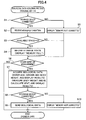
- Fig. 4 is a flowchart illustrating a control process executed by the main unit of the biological data acquiring apparatus 10.
- Fig. 5 is a diagram illustrating display examples of the liquid crystal display of the biological data acquiring apparatus 10.
- Fig. 6 is a flowchart illustrating a control process executed by the storage device of the biological data acquiring apparatus 10.
- the biological data acquiring apparatus 10 comprises a main unit 11 and a storage device 1 which is independent of and detachable from the main unit 11.
- the apparatus 10 can send biological data acquired in the main unit 11 of a user, such as age, gender, a body height, a body weight, a bioelectrical impedance, a body fat mass (percentage), a total body water (percentage), a muscle mass (percentage), a visceral fat area (level), a bone mass, a bone density, a basal metabolic rate and the like, to the external data processing device 30 via the storage device 1 as indicated by the dotted lines.
- the main unit 11 is an improved version of a known so-called scale equipped with a body fat monitor which takes in biological data of a user such as age, gender and a body height, measures the body weight and bioelectrical impedance of the user and calculates the body fat mass (percentage), total body water (percentage), muscle mass (percentage), visceral fat area (level), bone mass, bone density, basal metabolic rate and the like, based on these entered and measured data.
- the above biological data to be input will be generically referred to as "personal data”
- the above biological data to be measured or calculated will be generically referred to as "measurement data” hereinafter.
- This main unit 11 is basically constituted as a scale having a known load cell 12 (refer to Fig. 2) incorporated therein.
- input switches 13 which are used by a user to input personal data
- electrodes 14 which make contact with the bottoms of the feet of the user to measure a bioelectrical impedance
- a liquid crystal display 15 which displays personal data and measurement data
- an installation section 16 in which the storage device 1 to be described later is installed.
- personal key switches 17 which comprise four personal key switches 17a, 17b, 17c and 17d and a power-off switch 18. Each of the switches 17a to 17d can also serve as a power-on switch.
- the electrodes 14 comprise electrodes 14a and 14b which make contact with the bottom of the left foot of the user and electrodes 14c and 14d which make contact with the bottom of the right foot of the user.
- the electrodes 14a and 14c which make contact with the toe sides of the feet are used to pass a weak current between the feet
- the electrodes 14b and 14d which make contact with the heel sides of the feet are used to measure a potential difference (voltage) between the feet.
- a bioelectrical impedance can be determined from these current value and voltage value.
- the installation section 16 for the storage device 1 to be described later is formed in the central portion between the electrodes 14a and 14b for the left foot and the electrodes 14c and 14d for the right foot of the top surface 11a of the main unit.
- the installation section 16 is formed as a fitting cavity 16b of such a size that the storage device 1 to be described later can be fitted therein in a laid position.
- the cavity has an openable/closable cover 16a.
- a terminal 21 (refer to Fig. 2) which is used to connect the storage device 1 to the main unit is provided.
- the storage device 1 can be attached and detached more easily than when the installation section 16 is formed on the side or rear surface of the main unit 11. Further, when the installation section 16 has the foregoing structure that the storage device 1 can be fitted therein in a laid position, it can be prevented that the storage device 1 sticks out from the top surface 11a at the time of its installation without increasing the thickness of the main unit 11 so much, thereby making it difficult to occur that a user mistakenly steps on the storage device 1 and breaks it. Further, with the openable/closable cover 16a, the possibility of occurrence of such a breakage is further reduced to a significant degree.
- the position and shape of the installation section 16 need not be limited to those in the present example and may be any appropriate position and shape according to the sizes and other features of the storage device 1 and main unit 11.
- the installation section 16 may be formed in the unit.
- the storage device 1 is an improved version of a known so-called USB memory which has already been commercially available in various forms as an external memory for a personal computer having a terminal conforming to the USB (Universal Serial Bus) standard.
- the size and shape of the storage device 1 are nearly the same as those of a chewing gum package. It has a male USB terminal 2 at one end in its longitudinal direction and can be easily connected to the main unit 11 and the data processing device 30 which have a terminal corresponding to the USB terminal 2. Thereby, the storage device 1 exchanges data with these main unit 11 and data processing device 30 as host devices.
- the biological data acquiring apparatus 10 (main unit 11 and storage device 1) has a circuit configuration as shown in Fig. 2 therein.
- a microcomputer 20 which comprises a CPU, a ROM and a RAM to accept input of personal data from a user and to measure or calculate measurement data is incorporated.
- the terminal 21 which corresponds to the USB terminal 2 of the storage device 1 is connected via a data bus D5.
- a weighing circuit 22 which is connected to the above load cell 12, an input circuit 23 which is connected to the input switches 13, an impedance circuit 24 which is connected to the electrodes 14, a display output circuit 25 which is connected to the liquid crystal display 15, and a power supply circuit 27 which is connected to the personal key switches 17 and power-off switch 18 and a battery 28 are also connected to the microcomputer 20 via respective data buses or control signal buses.
- these microcomputer 20, terminal 21 and circuits 22 to 25 are connected to the power supply circuit 27 via a power supply line VI.
- the main unit 11 may incorporate an EEPROM 26 for storing personal data and measurement data.
- the microcomputer 20 calculates a body fat percentage and other data, based on a body weight measured by the load cell 12 and the weighing circuit 22, personal data entered by the input switches 13 and the input circuit 23 and a bioelectrical impedance measured by the electrodes 14 and the impedance circuit 24. Further, the microcomputer 20 outputs entered personal data and measured or calculated measurement data (i.e., biological data) to the liquid crystal display 15 via the display output circuit 25 and displays the data on the liquid crystal display 15. Further, the microcomputer 20 sends these biological data to the storage device 1 via the terminal 21. In addition, the microcomputer 20 also performs various other operations, e.g. , timing and updating date and time data constantly by a built-in clock.
- various other operations e.g. , timing and updating date and time data constantly by a built-in clock.
- the storage device 1 comprises the above USB terminal 2, an analog switch 3 which is used to select a data signal to be exchanged with the main unit 11 or the data processing device 30 as a host device, a microcomputer 4 which executes controls related to processing and storing of a data signal, and an EEPROM 5.
- the EEPROM 5 may be replaced to any other rewritable storage medium capable of storing data such as a nonvolatile memory.
- a flash memory may be used alternatively.
- the USB terminal 2 is connected to the analog switch 3 via a data bus D1.
- the analog switch 3 is connected to the microcomputer 4 via data buses D2 and D3 and a control signal bus C1.
- the microcomputer 4 is connected to the EEPROM 5 via a data bus D4.
- the analog switch 3, the microcomputer 4 and the EEPROM 5 are connected to the USB terminal 2 via a power supply line (not shown). Therefore, this storage device 1 operates by receiving power supplied from the host device via the USB terminal 2, as in the case of many other devices which conform to the USB standard.
- the CPU in the microcomputer 20 of the main unit 11 is not as high in processing power as a CPU incorporated in a personal computer or equivalent devices and consequently does not support data transmission conforming to the USB standard.
- transmission of data from the main unit 11 to the storage device 1 relies on serial transmission using a serial signal such as RS232C (as indicated by the dotted lines SERIAL in Fig. 1).
- the data processing device 30 shown in Fig. 1 is a so-called desktop personal computer which supports data transmission conforming to the USB standard and has a female USB terminal 31. Further, in the data processing device 30, history management software capable of, for example, graphically displaying the history of changes in biological data on the monitor and driver software for controlling the storage device 1 are installed.
- the microcomputer 4 of the storage device 1 When the history management software is activated in the data processing device 30 and the USB terminal 2 of the storage device 1 is connected to the USB terminal 31 of the data processing device 30, the microcomputer 4 of the storage device 1 reads out biological data stored in the EEPROM 5 via the data bus D4, and then sends the biological data to the data processing device 30 via the data bus D3, analog switch 3, data bus D1 and USB terminal 2 (as indicated by the dotted lines USB in Fig. 1). Then, in the data processing device 30, management of the history of the received biological data is performed in accordance with the history management software.
- the load cell 12 and weighing circuit 22, the input switches 13 and input circuit 23, the electrodes 14 and impedance circuit 24 and the microcomputer 20 constitute a biological data acquiring section for acquiring biological data;
- the EEPROM 5 constitutes a biological data storing section for storing biological data;
- the microcomputer 20 and the microcomputer 4 constitute a control section for controlling these biological data acquiring section and biological data storing section.
- the liquid crystal display section 15 and the display output circuit 25 constitute a biological data displaying section for displaying biological data
- the storage device 1 constitutes biological data sending means for sending biological data to the external data processing device 30.
- the EEPROM 5 as the biological data storing section may be not only incorporated into the storage device 1 which is independent of and detachable from the main unit 11 as in the present example but also incorporated directly into the main unit 11, as exemplified by the EEPROM 26 shown by the dotted lines in Fig. 2.
- the biological data sending means may be constituted by a communication cable which connects the main unit 11 and the data processing device 30 to each other or wireless communication equipment using an infrared ray or radio waves.
- the biological data sending means when the biological data sending means is constituted by the storage device 1 having the EEPROM 5 as the biological data storing section as in the present example, it can be placed at a site distant from the main unit 11 and the data processing device 30, as compared with when the biological data sending means is constituted by the communication cable or infrared communication equipment, and it can be an inexpensive device, as compared with when the biological data sending means is constituted by radio wave communication equipment.
- program software to be installed in the data processing terminal 30 a variety of program software such as one which gives a user, for example, advice about health management based on received biological data and one which transmits these biological data to others (e.g., the user's doctor) via the Internet or other route can be conceived.
- the EEPROM 5 as the biological data storing section.
- four fields 51, 52, 53 and 54 which correspond to the above four personal key switches 17a, 17b, 17c and 17d, respectively, are formed.
- the fields 51, 52, 53 and 54 comprise header information fields 51a, 52a, 53a and 54a and data storage fields 51b, 52b, 53b and 54b, respectively.
- the header information fields 51a to 54a each store information comprising four items(hereinafter generically referred to as "header information”),i.e., the number of a corresponding personal key switch (hereinafter referred to as “personal number”), a value representing the total capacity of a corresponding data storage field (hereinafter abbreviated as “total capacity”), a value representing currently available space in the corresponding data storage field (hereinafter abbreviated as “available space”), and a data storage address pointer indicating where in the corresponding data storage field biological data is to be stored (hereinafter abbreviated as "address pointer").
- head information i.e., the number of a corresponding personal key switch (hereinafter referred to as “personal number”), a value representing the total capacity of a corresponding data storage field (hereinafter abbreviated as “total capacity”), a value representing currently available space in the corresponding data storage field (hereinafter abbreviated as “available space”), and a data
- the above available space corresponds to information about the storage space of the biological data storing section
- the above address pointer corresponds to information about the order of storage of biological data.
- the above header information field constitutes a space information storing section and an order information storing section.
- each of the data storage fields 51b to 54b a plurality of data storage addresses are formed for storing biological data acquired in the main unit 11 sequentially.
- one personal data storage address hereinafter referred to as "personal data address”
- ten measurement data storage addresses hereinafter referred to as “measurement data addresses”. Therefore, in this storage device 1, personal data for one user and measurement data for 10 measurements (for 10 days) can be stored per personal number.
- the number of the fields 51 to 54 is not limited to and may be smaller or larger than four. Further, the number of the measurement data addresses formed in the data storage fields 51b to 54b is not limited to 10 and may be smaller or larger than ten.
- the microcomputer 20 checks whether the storage device 1 is connected to the main unit 11. More specifically, the microcomputer 20 sends a predetermined connection confirmation command pulse to the storage device 1 via the data bus D5 and the terminal 21. Receiving this connection confirmation command pulse, the storage device 1 sends back a predetermined connection response command pulse to the main unit 11 immediately. Thus, if the microcomputer 20 receives the connection response command pulse within a very short predetermined time (for example, 100 milliseconds) after sending the connection confirmation command pulse, it determines that the storage device 1 is connected to the main unit 11 and proceeds to STEP S2.
- a very short predetermined time for example, 100 milliseconds
- the microcomputer 20 sends a header information request command pulse for requesting header information corresponding to the personal number 1 to the storage device 1.
- the storage device 1 specifies the header information field 51a storing the personal number 1, reads header information out of the field 51a, and sends back the information to the main unit 11.
- the microcomputer 20 receives the header information corresponding to the personal number 1.
- the microcomputer 20 determines whether available space in the data storage field 51b is 0 (zero) from the header information it has received in STEP S2.
- the initial value of the available space is set at 10, and each time biological data is stored in the data storage field 51b, it is basically decremented by 1 (refer to STEP S17 to be described later).
- the available space is 0, it indicates that measurement data are already stored in all of the ten measurement data addresses formed in the data storage field 51b. That is, in the present example, a state when the available space is 0 corresponds to a predetermined state when the biological data storing section has no available space left.
- the microcomputer 20 proceeds to STEP S4 when the available space is 0.
- the microcomputer 20 displays characters "MEMORY FULL” indicating that the EEPROM 5 as the biological data storing section has no storage space left, on the liquid crystal display 15, as shown in Fig. 5(a).
- the character display corresponds to the information about the storage state of the biological data storing section, and a storage state informing section for informing this information is integrated in the liquid crystal display 15. Since the liquid crystal display 15 also displays biological data as described above, it draws attention from a user easily. Therefore, by performing the character display with the liquid crystal display 15, the user can be securely informed of the storage state of the biological data storing section. In addition, by the character display, the user can easily recognize that the EEPROM 5 does not have any available space left and can expect that past measurement data already stored in the EEPROM 5 will be overwritten if measurements of body weight, body fat percentage and the like are still continued.
- the user can take appropriate steps, e.g., detaching the storage device 1 from the main unit 11 at this time and connecting the storage device 1 to the external data processing device 30 so as to send out the measurement data stored in the EEPROM 5 to the data processing device 30 (refer to STEPS S20 and S21 to be described later) or replacing the storage device 1 by another storage device 1 having some available space left.
- Means for informing the information about the storage state of the biological data storing section is not limited to character display as shown in Fig. 5(a). A more simplified symbol may be displayed in place of characters.
- the storage state informing section may not have to be integrated in the liquid crystal display 15 and may be provided, for example, as an LED which lights upon informing, in the vicinity of the input switches 13 or on the storage device 1 itself.
- the storage state informing section is not limited to those appealing to the visual sense of a user and may also be those appealing to the auditory sense of the user, e. g. , a buzzer which gives a beep sound. It may also be a proper combination of these character display, LED, buzzer and the like.
- the microcomputer 20 proceeds to STEP S6 to prepare for input or measurement of biological data by the user.
- the microcomputer 20 determines that the storage device 1 is not connected to the main unit 11 and proceeds to STEP S5.
- the microcomputer 20 displays characters "MEMORY NOT CONNECTED" indicating the storage device 1 is not connected to the main unit 11, on the liquid crystal display 15, as shown in Fig. 5 (b) .
- This character display may also be replaced by more simplified symbol display, an LED, a buzzer or the like.
- the microcomputer 20 proceeds to STEP S6 to prepare for input or measurement of biological data by the user.
- the microcomputer 20 skips STEP S4 and proceeds to STEP S6 to prepare for input or measurement of biological data by the user.
- the microcomputer 20 stands by for the start of input of personal data or the start of measurement of measurement data by the user for a predetermined standby time (e.g., 2 minutes). If no input is made from either the input switches 13 or the load cell 12 and the electrodes 14 within the standby time, the microcomputer 20 skips all subsequent steps to end this control process and shuts off power. On the other had, if inputs are made from either the input switches 13 or the load cell 12 and the electrodes 14, the microcomputer 20 proceeds to STEP S7.
- a predetermined standby time e.g. 2 minutes
- the microcomputer 20 not only acquires biological data but also displays the acquired biological data on the liquid crystal display 15. More specifically, when inputs are made from the input switches 13 in STEP S6, the microcomputer 20 acquires personal data in accordance with the inputs and displays the data in turn. Meanwhile, when inputs are made from the load cell 12 and the electrodes 14 in STEP S6, the microcomputer 20 measures a body weight and a bioelectrical impedance based on these inputs. Then, the microcomputer 20 reads out personal data stored in the data storage field 51a of the EEPROM 5 from the connected storage device 1 and calculates a body fat percentage and other data based on these body weight, bioelectrical impedance and personal data.
- Fig. 5(c) is a display example of a body weight
- Fig. 5(d) is a display example of a body fat percentage
- Fig. 5(e) is a display example of a basal metabolic rate. Displays of these measurement data are repeated for a predetermined number of times in a given time. In this case, the body fat percentage and other data are not calculated when the storage device 1 is not connected to the main unit 11 or when personal data are not yet stored in the EEPROM 5.
- STEP S8 the microcomputer 20 rechecks connection of the storage device 1 in the same manner as in the above STEP S1. If it has been confirmed that the storage device 1 is connected to the main unit 1, the microcomputer 20 proceeds to STEP S9. If it has not been confirmed, the microcomputer 20 proceeds to STEP S10.
- the microcomputer 20 sends the biological data acquired in the above STEP S7 to the storage device 1 via the data bus D5 and the terminal 21. Then, after passage of a predetermined standby time (e.g., 2 minutes), the microcomputer 20 ends this control process and shuts off power.
- a predetermined standby time e.g., 2 minutes
- the microcomputer 20 displays "MEMORY NOT CONENCTED" on the liquid crystal display 15 as in the above STEP S5. Then, after passage of a predetermined standby time (e.g. , 2 minutes), the microcomputer 20 ends this control process and shuts off power.
- a predetermined standby time e.g. , 2 minutes
- the biological data acquired in the above STEP S7 are displayed continuously on the liquid crystal display 15 until the microcomputer 20 shuts off power after the above STEP S9 or STEP S10.
- the microcomputer 4 in the storage device 1 is supplied with power required for its operation from the main unit 11 or the data processing device 30 as a host device.
- the microcomputer 4 checks whether the storage device 1 is currently connected to the main unit 11. More specifically, when the microcomputer 4 receives the above connection confirmation command pulse (refer to the above STEP S1) from the host device, it determines that the storage device 1 is connected to the main unit 11 and sends back the above connection response command pulse and proceeds to STEP S12. Meanwhile, when the microcomputer 4 receives a so-called bus reset signal (identification signal transmitted from a host device in data transmission conforming to the USB standard) from the host device, it determines that the storage device 1 is connected to the data processing device 30 and proceeds to STEP S20.
- a so-called bus reset signal identification signal transmitted from a host device in data transmission conforming to the USB standard
- the storage device 1 in the present example has the analog switch 3 for data bus switching between the USB terminal 2 and the microcomputer 4.
- the microcomputer 4 controls the analog switch 3 via the control signal bus C1, thereby making it possible to use the data bus D2 for data transmission using a serial signal between the storage device 1 and the main unit 11 or to use the data bus D3 for data transmission conforming to the USB standard between the storage device 1 and the data processing device 30.
- the microcomputer 4 receives the header information request command pulse (refer to the above STEP S2) from the main unit 11, specifies the header information field 51a storing the corresponding personal number (in this case, the personal number 1) out of the EEPROM 5, reads out header information stored therein and sends back the information to the main unit 11.
- the microcomputer 4 receives the biological data sent from the main unit 11 (refer to the above STEP S9).
- STEP S14 the microcomputer 4 determines whether the biological data received in STEP S13 is personal data. If it is personal data, the microcomputer 4 proceeds to STEP S15.
- the microcomputer 4 stores the personal data received in STEP S14 in the personal data address formed in the data storage field 51b. If personal data is already stored therein, it is overwritten by the received personal data.
- the microcomputer 4 proceeds from STEP S14 to STEP S16.
- the microcomputer 4 determines whether available space in the data storage field 51b is 0 (zero) from the header information read in STEP S12. As described above, the initial value of the available space is set at 10, and each time biological data is stored in the data storage field, it is basically decremented by 1 (refer to STEP S17 to be described later). The microcomputer 4 proceeds to STEP S17 when the available space is not 0, while it skips STEP S17 and proceeds to STEP S18 when the available space is 0.
- the microcomputer 4 decrements the current available space by 1 and proceeds to STEP S18.
- the main unit 11 will go through the following operations the next time the storage device 1 is connected to the main unit 11. That is, the main unit 11 receives header information containing the updated available space in the above STEP S2, determines that the available space of the data storage field is 0 in the above STEP S3, and displays characters "MEMORY FULL" on the liquid crystal display 15 in the above STEP S4. Further, at this time, since this STEP S17 is skipped in the storage device 1, updating of the available space is not performed, thereby leaving the available space at 0.
- This available space is reset to the initial value when stored biological data are sent out to the data processing device 30 (refer to STEP S21 to be described later). Accordingly, the characters "MEMORY FULL" are displayed in the main unit 11 all the time until the user sends out the biological data.
- the microcomputer 4 updates an address pointer pointing out where in the data storage field 51b measurement data is to be stored. Since ten measurement data addresses are formed in each data storage field as described above, numerical values of 1 to 10 are given as the address pointers, for example.
- the address pointer is updated by repeating a sequence of numerical values 1, 2, 3, ... 9, 10 sequentially. That is, if the current address pointer is 10, this value is updated to 1.
- measurement data for one day when it is desired that measurement data for one day be stored in one measurement data address and biological data for a total of 10 days be stored in the storage device 1, it is to be programmed that date and time data counted/updated in the main unit 11 is included into measurement data, the date and time data in the measurement data to be stored this time is compared with date and time data in measurement data stored last time, and the address pointer is not updated when they match each other (that is, when they are measurement data for the same day). Thus, measurement data for the same day is stored in the same measurement data address.
- the microcomputer 4 stores the measurement data in a measurement data address specified by the address pointer. If measurement data is already stored therein, it is overwritten. As a result, when the user has continued measurement in the above STEP S6 despite displaying the characters "MEMORY FULL" on the liquid crystal display 15 in the above STEP S4, this implies that the user permits deletion of stored data, so that stored measurement data are overwritten and deleted in turn from the oldest measurement data.
- the process of storing the measurement data in the above STEP S19 is performed after the process of updating the available space in the above STEPS S16 and S17 and the process of updating the address pointer in the above STEP S18.
- the storing process may be carried out before these updating processes.
- the microcomputer 4 sends biological data to the data processing device 30. More specifically, when the microcomputer 4 receives a biological data requesting signal sent from the data processing device 30 in accordance with the above history management software or the like, the microcomputer 4 sends personal data and measurement data stored in the data storage field to the data processing device 30 by means of data transmission conforming to the USB standard. Thereafter, the microcomputer 4 proceeds to STEP S21.
- STEP S21 the microcomputer 4 resets the available space in the data storage field which has sent out the biological data in STEP S20 to the initial value, i.e., 10. As a result, next time the storage device 1 is connected to the main unit 11, it is determined in the above STEP S3 that the available space is not 0, and "MEMORY FULL" will not be displayed.
- a biological data acquiring apparatus to which the present invention can be applied is not limited to a body-fat-monitor-incorporated scale of a type which measures a bioelectrical impedance between both feet as in the above example and may be a type which measures a bioelectrical impedance between both hands and/or between a hand and a foot or may also be a biological data acquiring apparatus other than the body-fat-monitor-incorporated scale, e.g., a pedometer, a blood pressure meter or a thermometer.
Abstract
Description
-
- (i) Field of the Invention This invention relates to a biological data acquiring apparatus for acquiring biological data of a user and a storage device for the biological data acquiring apparatus. Particularly, it relates to a biological data acquiring apparatus which has a biological data storing section for storing acquired biological data and a storage device for the biological data acquiring apparatus.
- (ii) Description of the Related Art
Various biological data acquiring apparatuses which
acquire biological data of a user such as a body weight, a body
fat percentage, pulses and the number of steps have been
developed and practically used. These biological data
acquiring apparatuses include those which directly measure a
body weight which is biological data of a user like a scale and
those which calculate desired biological data such as a body
fat mass (percentage), a total body water (percentage), a muscle
mass (percentage), a visceral fat area, a bone density and a
basal metabolic rate from measured biological data of a user,
i.e., a body weight and a bioelectrical impedance value, and
biological data entered by the user, e.g., a body height, age
and gender, like a body fat monitor (for example, refer to
Patent Publications 1 and 2). -
- Further, as such biological data acquiring apparatuses, those which store acquired biological data in a biological data storing section to, for example, allow a user to check changes in biological data within a given period are also known (for example, refer to Patent Publication 3).
- Further, in recent years, there are systems which make it possible to, for example, manage the long-term continuous change record of biological data, by sending biological data acquired by these biological data acquiring apparatuses to an external data processing device such as a personal computer and storing the biological data in the external device. As such systems, there are proposed systems which acquire biological data of a user such as the number of steps and a walking pace by use of a body motion sensor and a computing unit which are incorporated in a pedometer, send the biological data to a personal computer by means of a communication cable or an optical communication unit and perform calculations on the biological data and other biological data entered in the personal computer such as the body height, body weight, age and gender of the user to acquire biological data such as consumed calories and change records thereof (refer to Patent Publication 4).
- Japanese Patent Publication No. 5-49050
- Japanese Patent Laid-Open Publication No. 2001-70273
- Japanese Patent Laid-Open Publication No. 2001-190514
- Japanese Patent Laid-Open Publication No. 2000-41953
- Of the above conventional biological data acquiring apparatuses, particularly, in biological data acquiring apparatuses of a type which stores acquired biological data in a biological data storing section, when biological data are stored in the biological data storing section to its full storage capacity, past biological data stored therein are automatically overwritten and deleted, generally from the oldest biological data, by newly acquired biological data, whereby the newly acquired biological data is stored.
- Further, biological data acquiring apparatuses of a type which sends acquired biological data to an external data processing device and stores the acquired biological data in the device often store the acquired biological data in the biological data storing section thereof temporarily. In such a case as well, when biological data are stored in the biological data storing section to its full storage capacity, stored biological data are automatically overwritten and deleted by newly acquired biological data, whereby the newly acquired biological data is stored.
- If the biological data acquiring apparatuses are constituted such that past biological data stored in the biological data storing section are automatically deleted as described above when biological data are stored in the biological data storing section to its full storage capacity, the past biological data may be deleted against a user's intention even if the user does not desire deletion of the biological data. In particular, in the case of a biological data acquiring apparatus which is so constituted as not to be allowed to store a large amount of biological data in the biological data storing section thereof on the premise that biological data are sent to an external data processing device at a relatively short time interval (e.g., once in a week), if a user acquires biological data without performing the above data transmission at a certain time interval unintentionally, past biological data may be deleted and the above long-term continuous change record may be adversely affected.
- Therefore, an object of the present invention is to provide a biological data acquiring apparatus which can reduce a possibility that biological data stored in a biological data storing section is deleted against a user's intention and a storage device for such a biological data acquiring apparatus.
- Further, a secondary object of the present invention is to provide the biological data acquiring apparatus and storage device which can delete stored biological data and store the most recent biological data when the user permits deletion of the stored biological data.
- A biological data acquiring apparatus according to the present invention comprises:
- a biological data acquiring section for acquiring biological data,
- a biological data storing section for storing acquired biological data sequentially, and
- a control section for controlling these biological data
acquiring section and biological data storing section,
the apparatus further comprising:
- a space information storing section for storing information about the storage space of the biological data storing section, and
- a storage state informing section for informing information about the storage state of the biological data storing section, the control section updating the information about the storage space each time it stores biological data in the biological data storing section and outputting the information about the storage state to the storage state informing section based on the updated information about the storage space.
-
- Further, the biological data acquiring apparatus according to the present invention is desirably such that when the information about the storage space has reached a predetermined state indicating that the biological data storing section has no available space left by the updating of the information about the storage space, the control section outputs information indicating that the biological data storing section has no available space left to the storage state informing section as the information about the storage state and does not perform updating of the information about the storage space.
- Further, the biological data acquiring apparatus according to the present invention is desirably such that the apparatus further comprises an order information storing section containing information about the order of storage of biological data into the biological data storing section, and the control section updates the information about the order of storage each time it stores biological data in the biological data storing section and stores the biological data in the biological data storing section based on the updated information about the order of storage.
- Further, the biological data acquiring apparatus according to the present invention is desirably such that the apparatus further comprises biological data sending means for sending biological data stored in the biological data storing section to an external data processing device, and the control section resets the information about the storage space to an initial state when the biological data stored in the biological data storing section is sent to the external data processing device by the biological data sending means.
- Further, the biological data acquiring apparatus according to the present invention is desirably such that the biological data sending means is a storage device which is independent of and detachable from the apparatus's main unit incorporating at least the biological data acquiring section and incorporates at least the biological data storing section and the space information storing section.
- Further, the biological data acquiring apparatus according to the present invention is desirably such that the storage device further incorporates the order information storing section.
- Further, the biological data acquiring apparatus according to the present invention is desirably such that the apparatus further comprises a biological data displaying section for displaying biological data acquired by the biological data acquiring section, and the storage state informing section is integrated in the biological data displaying section.
- Alternatively, a storage device for a biological data acquiring apparatus according to the present invention is independent of and detachable from the main unit of a biological data acquiring apparatus which incorporates a biological data acquiring section for acquiring biological data and incorporates a biological data storing section for storing biological data acquired by the biological data acquiring section and a space information storing section containing information about the storage space of the biological data storing section.
- Further, the storage device for a biological data acquiring apparatus according to the present invention is desirably such that the device further comprises an order information storing section containing information about the order of storage of biological data into the biological data storing section.
- According to the biological data acquiring apparatus of the present invention, since information about the storage state of the biological data storing section is informed based on information about the storage space of the biological data storing section which is updated each time biological data is stored, a user can recognize the storage state of biological data in the biological data storing section. Therefore, a possibility that deletion of stored biological data is performed against the user's intention can be reduced.
- Further, if it is informed as the information about the storage state that the information about the storage space has been updated to a predetermined state indicating that the biological data storing section has no available space left and subsequent updating of the information about the storage space is cancelled, the user can be easily and always aware that currently stored biological data is overwritten and deleted if biological data is further acquired and stored. Thus, the possibility that deletion of stored biological data is performed against the user's intention can be reduced more securely.
- Further, if biological data is stored in the biological data storing section based on information about the order of storage of biological data which is updated each time biological data is stored, biological data with the oldest storage order is overwritten and deleted by newly acquired biological data and the most recent biological data can be stored because the user permits deletion of already stored biological data when the user continues acquisition of biological data even if the biological data storing section has no available space left.
- Further, if the information about the storage space is reset to an initial state when biological data stored in the biological data storing section are sent to an external data processing device by the biological data sending means, the information about the storage state which is informed after sending out the biological data can also be reset to an initial state. When this constitution is applied particularly to a constitution that it is informed as the information about the storage state that the biological data storing section has no available space left, the information about the storage state is not informed after sending out the biological data. Thus, unnecessary informing can be prevented, thereby attaining a rational biological data acquiring apparatus.
- Further, when the biological data sending means is a storage device which is independent of and detachable from the main unit of the biological data acquiring apparatus and incorporates at least the biological data storing section and the space information storing section, preferably further incorporates the order information storing section, the biological data sending means can be inexpensive and used regardless of the positions of the main unit of the biological data acquiring apparatus and the data processing device, and a user-friendly biological data acquiring apparatus which can perform, e.g., informing of the above information about the storage space of the biological data storing section can be obtained.
- Further, when the storage state informing section for informing the information about the storage state of the biological data storing section is integrated in the biological data displaying section for displaying biological data, it becomes possible that the information about the storage state of the biological data storing section is informed by use of the biological data displaying section which easily draws attention from the user. Thus, a possibility that the user overlooks the information about the storage state can be reduced.
- Meanwhile, according to the storage device for the biological data acquiring apparatus of the present invention, since it is independent of and detachable from the main unit of the biological data acquiring apparatus and incorporates at least the biological data storing section and the space information storing section, the information about the storage state of the biological data storing section can be informed based on the information about the storage space which is stored in the space information storing section. Further, when the storage device further comprises the order information storing section, biological data can be stored in the biological data storing section based on the information about the order of storage which is stored in the order information storing section. Thus, there can be obtained a storage device for a biological data acquiring apparatus which can allow the user to recognize the storage state of biological data in the biological data storing section and allow newly acquired biological data to overwrite and delete biological data with the oldest storage order and be stored in the biological data storing section.
-
- Fig. 1 is an external view of a biological data acquiring apparatus according to the present invention.
- Fig. 2 is a schematic diagram illustrating the circuit configuration of the biological data acquiring apparatus according to the present invention.
- Fig. 3 is a diagram illustrating the biological data storing section of the biological data acquiring apparatus according to the present invention.
- Fig. 4 is a flowchart illustrating a control process executed by the main unit of the biological data acquiring apparatus according to the present invention.
- Fig. 5 is a diagram wherein (a) to (e) show display examples of the liquid crystal display of the biological data acquiring apparatus according to the present invention.
- Fig. 6 is a flowchart illustrating a control process executed by the storage device of the biological data acquiring apparatus according to the present invention.
-
- A biological data acquiring apparatus according to the present invention comprises:
- a biological data acquiring section for acquiring biological data,
- a biological data storing section for storing acquired biological data sequentially, and
- a control section for controlling these biological data acquiring section and biological data storing section,
- the apparatus further comprising:
- a space information storing section for storing information about the storage space of the biological data storing section, and
- a storage state informing section for informing information about the storage state of the biological data storing section, the control section updating the information about the storage space each time it stores biological data in the biological data storing section and outputting the information about the storage state to the storage state informing section based on the updated information about the storage space.
-
- Further, the biological data acquiring apparatus according to the present invention is desirably such that when the information about the storage space has reached a predetermined state indicating that the biological data storing section has no available space left by the updating of the information about the storage space, the control section outputs information indicating that the biological data storing section has no available space left to the storage state informing section as the information about the storage state and does not perform updating of the information about the storage space.
- Further, the biological data acquiring apparatus according to the present invention is desirably such that the apparatus further comprises an order information storing section containing information about the order of storage of biological data into the biological data storing section, and the control section updates the information about the order of storage each time it stores biological data in the biological data storing section and stores the biological data in the biological data storing section based on the updated information about the order of storage.
- Further, the biological data acquiring apparatus according to the present invention is desirably such that the apparatus further comprises biological data sending means for sending biological data stored in the biological data storing section to an external data processing device, and the control section resets the information about the storage space to an initial state when the biological data stored in the biological data storing section is sent to the external data processing device by the biological data sending means.
- Further, the biological data acquiring apparatus according to the present invention is desirably such that the biological data sending means is a storage device which is independent of and detachable from the apparatus's main unit incorporating at least the biological data acquiring section and incorporates at least the biological data storing section and the space information storing section.
- Further, the biological data acquiring apparatus according to the present invention is desirably such that the storage device further incorporates the order information storing section.
- Further, the biological data acquiring apparatus according to the present invention is desirably such that the apparatus further comprises a biological data displaying section for displaying biological data acquired by the biological data acquiring section, and the storage state informing section is integrated in the biological data displaying section.
- Alternatively, a storage device for a biological data acquiring apparatus according to the present invention is independent of and detachable from the main unit of a biological data acquiring apparatus which incorporates a biological data acquiring section for acquiring biological data and incorporates a biological data storing section for storing biological data acquired by the biological data acquiring section and a space information storing section containing information about the storage space of the biological data storing section.
- Further, the storage device for a biological data acquiring apparatus according to the present invention is desirably such that the device further comprises an order information storing section containing information about the order of storage of biological data into the biological data storing section.
- Hereinafter, an example of the present invention will be described with reference to the drawings. Fig. 1 is an external view of a biological
data acquiring apparatus 10 as a suitable example of the present invention together with an externaldata processing device 30. Fig. 2 is a schematic diagram illustrating the circuit configuration of the biologicaldata acquiring apparatus 10. Fig. 3 is a diagram illustrating the constitution of the biological data storing section of the biologicaldata acquiring apparatus 10. Fig. 4 is a flowchart illustrating a control process executed by the main unit of the biologicaldata acquiring apparatus 10. Fig. 5 is a diagram illustrating display examples of the liquid crystal display of the biologicaldata acquiring apparatus 10. Fig. 6 is a flowchart illustrating a control process executed by the storage device of the biologicaldata acquiring apparatus 10. - As shown in Figs. 1 and 2, the biological
data acquiring apparatus 10 comprises amain unit 11 and astorage device 1 which is independent of and detachable from themain unit 11. Theapparatus 10 can send biological data acquired in themain unit 11 of a user, such as age, gender, a body height, a body weight, a bioelectrical impedance, a body fat mass (percentage), a total body water (percentage), a muscle mass (percentage), a visceral fat area (level), a bone mass, a bone density, a basal metabolic rate and the like, to the externaldata processing device 30 via thestorage device 1 as indicated by the dotted lines. - First of all, the
main unit 11 is an improved version of a known so-called scale equipped with a body fat monitor which takes in biological data of a user such as age, gender and a body height, measures the body weight and bioelectrical impedance of the user and calculates the body fat mass (percentage), total body water (percentage), muscle mass (percentage), visceral fat area (level), bone mass, bone density, basal metabolic rate and the like, based on these entered and measured data. In the present example, the above biological data to be input will be generically referred to as "personal data", and the above biological data to be measured or calculated will be generically referred to as "measurement data" hereinafter. - This
main unit 11 is basically constituted as a scale having a known load cell 12 (refer to Fig. 2) incorporated therein. On itstop surface 11a, there are provided input switches 13 which are used by a user to input personal data,electrodes 14 which make contact with the bottoms of the feet of the user to measure a bioelectrical impedance, aliquid crystal display 15 which displays personal data and measurement data, and aninstallation section 16 in which thestorage device 1 to be described later is installed. Further, on theside face 11b, there are provided personalkey switches 17 which comprise four personalkey switches off switch 18. Each of theswitches 17a to 17d can also serve as a power-on switch. - The
electrodes 14 compriseelectrodes electrodes electrodes electrodes - Further, in the central portion between the
electrodes electrodes top surface 11a of the main unit, theinstallation section 16 for thestorage device 1 to be described later is formed. Theinstallation section 16 is formed as afitting cavity 16b of such a size that thestorage device 1 to be described later can be fitted therein in a laid position. The cavity has an openable/closable cover 16a. On the internal surface of thefitting cavity 16b, a terminal 21 (refer to Fig. 2) which is used to connect thestorage device 1 to the main unit is provided. - When the
installation section 16 for thestorage device 1 is formed on thetop surface 11a of the main unit as described above, thestorage device 1 can be attached and detached more easily than when theinstallation section 16 is formed on the side or rear surface of themain unit 11. Further, when theinstallation section 16 has the foregoing structure that thestorage device 1 can be fitted therein in a laid position, it can be prevented that thestorage device 1 sticks out from thetop surface 11a at the time of its installation without increasing the thickness of themain unit 11 so much, thereby making it difficult to occur that a user mistakenly steps on thestorage device 1 and breaks it. Further, with the openable/closable cover 16a, the possibility of occurrence of such a breakage is further reduced to a significant degree. - As a matter of course, the position and shape of the
installation section 16 need not be limited to those in the present example and may be any appropriate position and shape according to the sizes and other features of thestorage device 1 andmain unit 11. For example, in the case of a biological data acquiring apparatus which has the input switches 13 and theliquid crystal display 15 as a unit which is detachable from or independent of themain unit 11, theinstallation section 16 may be formed in the unit. - Meanwhile, the
storage device 1 is an improved version of a known so-called USB memory which has already been commercially available in various forms as an external memory for a personal computer having a terminal conforming to the USB (Universal Serial Bus) standard. The size and shape of thestorage device 1 are nearly the same as those of a chewing gum package. It has amale USB terminal 2 at one end in its longitudinal direction and can be easily connected to themain unit 11 and thedata processing device 30 which have a terminal corresponding to theUSB terminal 2. Thereby, thestorage device 1 exchanges data with thesemain unit 11 anddata processing device 30 as host devices. - Further, the biological data acquiring apparatus 10 (
main unit 11 and storage device 1) has a circuit configuration as shown in Fig. 2 therein. - First, in the
main unit 11, amicrocomputer 20 which comprises a CPU, a ROM and a RAM to accept input of personal data from a user and to measure or calculate measurement data is incorporated. To themicrocomputer 20, the terminal 21 which corresponds to theUSB terminal 2 of thestorage device 1 is connected via a data bus D5. Further, a weighing circuit 22 which is connected to theabove load cell 12, aninput circuit 23 which is connected to the input switches 13, animpedance circuit 24 which is connected to theelectrodes 14, adisplay output circuit 25 which is connected to theliquid crystal display 15, and apower supply circuit 27 which is connected to the personalkey switches 17 and power-off switch 18 and abattery 28 are also connected to themicrocomputer 20 via respective data buses or control signal buses. Further, thesemicrocomputer 20,terminal 21 and circuits 22 to 25 are connected to thepower supply circuit 27 via a power supply line VI. - Further, aside from the
storage device 1, themain unit 11 may incorporate anEEPROM 26 for storing personal data and measurement data. - Further, the
microcomputer 20 calculates a body fat percentage and other data, based on a body weight measured by theload cell 12 and the weighing circuit 22, personal data entered by the input switches 13 and theinput circuit 23 and a bioelectrical impedance measured by theelectrodes 14 and theimpedance circuit 24. Further, themicrocomputer 20 outputs entered personal data and measured or calculated measurement data (i.e., biological data) to theliquid crystal display 15 via thedisplay output circuit 25 and displays the data on theliquid crystal display 15. Further, themicrocomputer 20 sends these biological data to thestorage device 1 via theterminal 21. In addition, themicrocomputer 20 also performs various other operations, e.g. , timing and updating date and time data constantly by a built-in clock. - Meanwhile, the
storage device 1 comprises theabove USB terminal 2, ananalog switch 3 which is used to select a data signal to be exchanged with themain unit 11 or thedata processing device 30 as a host device, amicrocomputer 4 which executes controls related to processing and storing of a data signal, and anEEPROM 5. As a matter of course, theEEPROM 5 may be replaced to any other rewritable storage medium capable of storing data such as a nonvolatile memory. For example, a flash memory may be used alternatively. - The
USB terminal 2 is connected to theanalog switch 3 via a data bus D1. Theanalog switch 3 is connected to themicrocomputer 4 via data buses D2 and D3 and a control signal bus C1. Themicrocomputer 4 is connected to theEEPROM 5 via a data bus D4. Theanalog switch 3, themicrocomputer 4 and theEEPROM 5 are connected to theUSB terminal 2 via a power supply line (not shown). Therefore, thisstorage device 1 operates by receiving power supplied from the host device via theUSB terminal 2, as in the case of many other devices which conform to the USB standard. - When the
USB terminal 2 of thestorage device 1 is connected to theterminal 21 of themain unit 11, biological data acquired in themain unit 11 are received by themicrocomputer 4 via theUSB terminal 2, data bus D1,analog switch 3 and data bus D2, and then stored in theEEPROM 5 via the data bus D4 from themicrocomputer 4. - The CPU in the
microcomputer 20 of themain unit 11 is not as high in processing power as a CPU incorporated in a personal computer or equivalent devices and consequently does not support data transmission conforming to the USB standard. Thus, transmission of data from themain unit 11 to thestorage device 1 relies on serial transmission using a serial signal such as RS232C (as indicated by the dotted lines SERIAL in Fig. 1). - Meanwhile, the
data processing device 30 shown in Fig. 1 is a so-called desktop personal computer which supports data transmission conforming to the USB standard and has afemale USB terminal 31. Further, in thedata processing device 30, history management software capable of, for example, graphically displaying the history of changes in biological data on the monitor and driver software for controlling thestorage device 1 are installed. - When the history management software is activated in the
data processing device 30 and theUSB terminal 2 of thestorage device 1 is connected to theUSB terminal 31 of thedata processing device 30, themicrocomputer 4 of thestorage device 1 reads out biological data stored in theEEPROM 5 via the data bus D4, and then sends the biological data to thedata processing device 30 via the data bus D3,analog switch 3, data bus D1 and USB terminal 2 (as indicated by the dotted lines USB in Fig. 1). Then, in thedata processing device 30, management of the history of the received biological data is performed in accordance with the history management software. - That is, in the biological
data acquiring apparatus 10 of the present example, theload cell 12 and weighing circuit 22, the input switches 13 andinput circuit 23, theelectrodes 14 andimpedance circuit 24 and themicrocomputer 20 constitute a biological data acquiring section for acquiring biological data; theEEPROM 5 constitutes a biological data storing section for storing biological data; and themicrocomputer 20 and themicrocomputer 4 constitute a control section for controlling these biological data acquiring section and biological data storing section. Further, the liquidcrystal display section 15 and thedisplay output circuit 25 constitute a biological data displaying section for displaying biological data, and thestorage device 1 constitutes biological data sending means for sending biological data to the externaldata processing device 30. - The
EEPROM 5 as the biological data storing section may be not only incorporated into thestorage device 1 which is independent of and detachable from themain unit 11 as in the present example but also incorporated directly into themain unit 11, as exemplified by theEEPROM 26 shown by the dotted lines in Fig. 2. Further, the biological data sending means may be constituted by a communication cable which connects themain unit 11 and thedata processing device 30 to each other or wireless communication equipment using an infrared ray or radio waves. However, when the biological data sending means is constituted by thestorage device 1 having theEEPROM 5 as the biological data storing section as in the present example, it can be placed at a site distant from themain unit 11 and thedata processing device 30, as compared with when the biological data sending means is constituted by the communication cable or infrared communication equipment, and it can be an inexpensive device, as compared with when the biological data sending means is constituted by radio wave communication equipment. - Further, as program software to be installed in the
data processing terminal 30, a variety of program software such as one which gives a user, for example, advice about health management based on received biological data and one which transmits these biological data to others (e.g., the user's doctor) via the Internet or other route can be conceived. - Next, a detailed description will be given to the
EEPROM 5 as the biological data storing section. As shown in Fig. 3, in theEEPROM 5, fourfields key switches fields header information fields data storage fields - The header information fields 51a to 54a each store information comprising four items(hereinafter generically referred to as "header information"),i.e., the number of a corresponding personal key switch (hereinafter referred to as "personal number"), a value representing the total capacity of a corresponding data storage field (hereinafter abbreviated as "total capacity"), a value representing currently available space in the corresponding data storage field (hereinafter abbreviated as "available space"), and a data storage address pointer indicating where in the corresponding data storage field biological data is to be stored (hereinafter abbreviated as "address pointer"). That is, in the present example, the above available space corresponds to information about the storage space of the biological data storing section, and the above address pointer corresponds to information about the order of storage of biological data. Thus, the above header information field constitutes a space information storing section and an order information storing section.
- Further, in each of the data storage fields 51b to 54b, a plurality of data storage addresses are formed for storing biological data acquired in the
main unit 11 sequentially. In the present example, in each of the data storage fields 51b to 54b, one personal data storage address (hereinafter referred to as "personal data address") and ten measurement data storage addresses (hereinafter referred to as "measurement data addresses") are formed. Therefore, in thisstorage device 1, personal data for one user and measurement data for 10 measurements (for 10 days) can be stored per personal number. - The number of the
fields 51 to 54 is not limited to and may be smaller or larger than four. Further, the number of the measurement data addresses formed in the data storage fields 51b to 54b is not limited to 10 and may be smaller or larger than ten. - Next, a control process executed by the
main unit 11 of the biologicaldata acquiring apparatus 10 will be described with reference to the flowchart of Fig. 4. Further, display examples of theliquid crystal display 15 will also be described with reference to Fig. 5. - When a user presses down any of the personal
key switches 17a to 17d of themain unit 11, electrical power is supplied from thebattery 28 to each section of themain unit 11 via thepower supply circuit 27, and in themicrocomputer 20, a personal number corresponding to the pressed personal key switch is specified and the control process in accordance with the flowchart of Fig. 4 is executed. In this case, it is assumed that the personalkey switch 17a has been pressed down and apersonal number 1 has been specified. - In STEP S1, the
microcomputer 20 checks whether thestorage device 1 is connected to themain unit 11. More specifically, themicrocomputer 20 sends a predetermined connection confirmation command pulse to thestorage device 1 via the data bus D5 and the terminal 21. Receiving this connection confirmation command pulse, thestorage device 1 sends back a predetermined connection response command pulse to themain unit 11 immediately. Thus, if themicrocomputer 20 receives the connection response command pulse within a very short predetermined time (for example, 100 milliseconds) after sending the connection confirmation command pulse, it determines that thestorage device 1 is connected to themain unit 11 and proceeds to STEP S2. - In STEP S2, first, the
microcomputer 20 sends a header information request command pulse for requesting header information corresponding to thepersonal number 1 to thestorage device 1. Receiving this header information request command pulse, thestorage device 1 specifies theheader information field 51a storing thepersonal number 1, reads header information out of thefield 51a, and sends back the information to themain unit 11. Then, themicrocomputer 20 receives the header information corresponding to thepersonal number 1. - In STEP S3, the
microcomputer 20 determines whether available space in thedata storage field 51b is 0 (zero) from the header information it has received in STEP S2. In the present example, the initial value of the available space is set at 10, and each time biological data is stored in thedata storage field 51b, it is basically decremented by 1 (refer to STEP S17 to be described later). Thus, if the available space is 0, it indicates that measurement data are already stored in all of the ten measurement data addresses formed in thedata storage field 51b. That is, in the present example, a state when the available space is 0 corresponds to a predetermined state when the biological data storing section has no available space left. Themicrocomputer 20 proceeds to STEP S4 when the available space is 0. - In STEP S4, the
microcomputer 20 displays characters "MEMORY FULL" indicating that theEEPROM 5 as the biological data storing section has no storage space left, on theliquid crystal display 15, as shown in Fig. 5(a). - That is, in the present example, the character display corresponds to the information about the storage state of the biological data storing section, and a storage state informing section for informing this information is integrated in the
liquid crystal display 15. Since theliquid crystal display 15 also displays biological data as described above, it draws attention from a user easily. Therefore, by performing the character display with theliquid crystal display 15, the user can be securely informed of the storage state of the biological data storing section. In addition, by the character display, the user can easily recognize that theEEPROM 5 does not have any available space left and can expect that past measurement data already stored in theEEPROM 5 will be overwritten if measurements of body weight, body fat percentage and the like are still continued. Thus, when the user does not want the past measurement data to be deleted, the user can take appropriate steps, e.g., detaching thestorage device 1 from themain unit 11 at this time and connecting thestorage device 1 to the externaldata processing device 30 so as to send out the measurement data stored in theEEPROM 5 to the data processing device 30 (refer to STEPS S20 and S21 to be described later) or replacing thestorage device 1 by anotherstorage device 1 having some available space left. - Means for informing the information about the storage state of the biological data storing section is not limited to character display as shown in Fig. 5(a). A more simplified symbol may be displayed in place of characters. Further, the storage state informing section may not have to be integrated in the
liquid crystal display 15 and may be provided, for example, as an LED which lights upon informing, in the vicinity of the input switches 13 or on thestorage device 1 itself. In addition, the storage state informing section is not limited to those appealing to the visual sense of a user and may also be those appealing to the auditory sense of the user, e. g. , a buzzer which gives a beep sound. It may also be a proper combination of these character display, LED, buzzer and the like. - After STEP S4, the
microcomputer 20 proceeds to STEP S6 to prepare for input or measurement of biological data by the user. - Meanwhile, if the
microcomputer 20 does not receive the connection response command pulse in the above STEP S1, it determines that thestorage device 1 is not connected to themain unit 11 and proceeds to STEP S5. In STEP S5, themicrocomputer 20 displays characters "MEMORY NOT CONNECTED" indicating thestorage device 1 is not connected to themain unit 11, on theliquid crystal display 15, as shown in Fig. 5 (b) . This character display may also be replaced by more simplified symbol display, an LED, a buzzer or the like. Then, themicrocomputer 20 proceeds to STEP S6 to prepare for input or measurement of biological data by the user. - Further, if the available space is not 0 (that is, the
EEPROM 5 still has some available space left) in the above STEP S3, themicrocomputer 20 skips STEP S4 and proceeds to STEP S6 to prepare for input or measurement of biological data by the user. - In STEP S6, the
microcomputer 20 stands by for the start of input of personal data or the start of measurement of measurement data by the user for a predetermined standby time (e.g., 2 minutes). If no input is made from either the input switches 13 or theload cell 12 and theelectrodes 14 within the standby time, themicrocomputer 20 skips all subsequent steps to end this control process and shuts off power. On the other had, if inputs are made from either the input switches 13 or theload cell 12 and theelectrodes 14, themicrocomputer 20 proceeds to STEP S7. - In STEP S7, the
microcomputer 20 not only acquires biological data but also displays the acquired biological data on theliquid crystal display 15. More specifically, when inputs are made from the input switches 13 in STEP S6, themicrocomputer 20 acquires personal data in accordance with the inputs and displays the data in turn. Meanwhile, when inputs are made from theload cell 12 and theelectrodes 14 in STEP S6, themicrocomputer 20 measures a body weight and a bioelectrical impedance based on these inputs. Then, themicrocomputer 20 reads out personal data stored in thedata storage field 51a of theEEPROM 5 from the connectedstorage device 1 and calculates a body fat percentage and other data based on these body weight, bioelectrical impedance and personal data. The thus acquired measurement data are displayed in turn on theliquid crystal display 15, as exemplified in Figs. 5(c) to 5(e). Fig. 5(c) is a display example of a body weight, Fig. 5(d) is a display example of a body fat percentage, and Fig. 5(e) is a display example of a basal metabolic rate. Displays of these measurement data are repeated for a predetermined number of times in a given time. In this case, the body fat percentage and other data are not calculated when thestorage device 1 is not connected to themain unit 11 or when personal data are not yet stored in theEEPROM 5. - In STEP S8, the
microcomputer 20 rechecks connection of thestorage device 1 in the same manner as in the above STEP S1. If it has been confirmed that thestorage device 1 is connected to themain unit 1, themicrocomputer 20 proceeds to STEP S9. If it has not been confirmed, themicrocomputer 20 proceeds to STEP S10. - In STEP S9, the
microcomputer 20 sends the biological data acquired in the above STEP S7 to thestorage device 1 via the data bus D5 and the terminal 21. Then, after passage of a predetermined standby time (e.g., 2 minutes), themicrocomputer 20 ends this control process and shuts off power. - In STEP S10, the
microcomputer 20 displays "MEMORY NOT CONENCTED" on theliquid crystal display 15 as in the above STEP S5. Then, after passage of a predetermined standby time (e.g. , 2 minutes), themicrocomputer 20 ends this control process and shuts off power. - The biological data acquired in the above STEP S7 are displayed continuously on the
liquid crystal display 15 until themicrocomputer 20 shuts off power after the above STEP S9 or STEP S10. - Next, a control process executed by the
storage device 1 of the biologicaldata acquiring apparatus 10 will be described with reference to the flowchart of Fig. 6. Themicrocomputer 4 in thestorage device 1 is supplied with power required for its operation from themain unit 11 or thedata processing device 30 as a host device. - In STEP S11, the
microcomputer 4 checks whether thestorage device 1 is currently connected to themain unit 11. More specifically, when themicrocomputer 4 receives the above connection confirmation command pulse (refer to the above STEP S1) from the host device, it determines that thestorage device 1 is connected to themain unit 11 and sends back the above connection response command pulse and proceeds to STEP S12. Meanwhile, when themicrocomputer 4 receives a so-called bus reset signal (identification signal transmitted from a host device in data transmission conforming to the USB standard) from the host device, it determines that thestorage device 1 is connected to thedata processing device 30 and proceeds to STEP S20. - The
storage device 1 in the present example has theanalog switch 3 for data bus switching between theUSB terminal 2 and themicrocomputer 4. Themicrocomputer 4 controls theanalog switch 3 via the control signal bus C1, thereby making it possible to use the data bus D2 for data transmission using a serial signal between thestorage device 1 and themain unit 11 or to use the data bus D3 for data transmission conforming to the USB standard between thestorage device 1 and thedata processing device 30. - In STEP S12, the
microcomputer 4 receives the header information request command pulse (refer to the above STEP S2) from themain unit 11, specifies theheader information field 51a storing the corresponding personal number (in this case, the personal number 1) out of theEEPROM 5, reads out header information stored therein and sends back the information to themain unit 11. - In STEP S13, the
microcomputer 4 receives the biological data sent from the main unit 11 (refer to the above STEP S9). - In STEP S14, the
microcomputer 4 determines whether the biological data received in STEP S13 is personal data. If it is personal data, themicrocomputer 4 proceeds to STEP S15. - In STEP S15, the
microcomputer 4 stores the personal data received in STEP S14 in the personal data address formed in thedata storage field 51b. If personal data is already stored therein, it is overwritten by the received personal data. - Meanwhile, if the biological data received in STEP S14 is not personal data but measurement data, the
microcomputer 4 proceeds from STEP S14 to STEP S16. - In STEP S16, the
microcomputer 4 determines whether available space in thedata storage field 51b is 0 (zero) from the header information read in STEP S12. As described above, the initial value of the available space is set at 10, and each time biological data is stored in the data storage field, it is basically decremented by 1 (refer to STEP S17 to be described later). Themicrocomputer 4 proceeds to STEP S17 when the available space is not 0, while it skips STEP S17 and proceeds to STEP S18 when the available space is 0. - In STEP S17, the
microcomputer 4 decrements the current available space by 1 and proceeds to STEP S18. When the available space becomes 0 as a result of the decrementation, themain unit 11 will go through the following operations the next time thestorage device 1 is connected to themain unit 11. That is, themain unit 11 receives header information containing the updated available space in the above STEP S2, determines that the available space of the data storage field is 0 in the above STEP S3, and displays characters "MEMORY FULL" on theliquid crystal display 15 in the above STEP S4. Further, at this time, since this STEP S17 is skipped in thestorage device 1, updating of the available space is not performed, thereby leaving the available space at 0. This available space is reset to the initial value when stored biological data are sent out to the data processing device 30 (refer to STEP S21 to be described later). Accordingly, the characters "MEMORY FULL" are displayed in themain unit 11 all the time until the user sends out the biological data. - In STEP S18, the
microcomputer 4 updates an address pointer pointing out where in thedata storage field 51b measurement data is to be stored. Since ten measurement data addresses are formed in each data storage field as described above, numerical values of 1 to 10 are given as the address pointers, for example. The address pointer is updated by repeating a sequence ofnumerical values - For instance, when it is desired that measurement data for one day be stored in one measurement data address and biological data for a total of 10 days be stored in the
storage device 1, it is to be programmed that date and time data counted/updated in themain unit 11 is included into measurement data, the date and time data in the measurement data to be stored this time is compared with date and time data in measurement data stored last time, and the address pointer is not updated when they match each other (that is, when they are measurement data for the same day). Thus, measurement data for the same day is stored in the same measurement data address. - In STEP S19, the
microcomputer 4 stores the measurement data in a measurement data address specified by the address pointer. If measurement data is already stored therein, it is overwritten. As a result, when the user has continued measurement in the above STEP S6 despite displaying the characters "MEMORY FULL" on theliquid crystal display 15 in the above STEP S4, this implies that the user permits deletion of stored data, so that stored measurement data are overwritten and deleted in turn from the oldest measurement data. - In the present example, the process of storing the measurement data in the above STEP S19 is performed after the process of updating the available space in the above STEPS S16 and S17 and the process of updating the address pointer in the above STEP S18. However, the storing process may be carried out before these updating processes.
- Meanwhile, if the
storage device 1 is connected to thedata processing device 30 in the above STEP S11, themicrocomputer 4 proceeds to STEP S20 as described above. - In STEP S20, the
microcomputer 4 sends biological data to thedata processing device 30. More specifically, when themicrocomputer 4 receives a biological data requesting signal sent from thedata processing device 30 in accordance with the above history management software or the like, themicrocomputer 4 sends personal data and measurement data stored in the data storage field to thedata processing device 30 by means of data transmission conforming to the USB standard. Thereafter, themicrocomputer 4 proceeds to STEP S21. - In STEP S21, the
microcomputer 4 resets the available space in the data storage field which has sent out the biological data in STEP S20 to the initial value, i.e., 10. As a result, next time thestorage device 1 is connected to themain unit 11, it is determined in the above STEP S3 that the available space is not 0, and "MEMORY FULL" will not be displayed. - Although a suitable example of the present invention has been described above, it is needless to say that various modifications as mentioned as appropriate in the description of the present example can be made to the present invention. Further, a biological data acquiring apparatus to which the present invention can be applied is not limited to a body-fat-monitor-incorporated scale of a type which measures a bioelectrical impedance between both feet as in the above example and may be a type which measures a bioelectrical impedance between both hands and/or between a hand and a foot or may also be a biological data acquiring apparatus other than the body-fat-monitor-incorporated scale, e.g., a pedometer, a blood pressure meter or a thermometer.
Claims (9)
- A biological data acquiring apparatus comprising:a biological data acquiring section for acquiring biological data,a biological data storing section for storing acquired biological data sequentially, anda control section for controlling these biological data acquiring section and biological data storing section, the apparatus further comprising:a space information storing section for storing information about the storage space of the biological data storing section, anda storage state informing section for informing information about the storage state of the biological data storing section, the control section updating the information about the storage space each time it stores biological data in the biological data storing section and outputting the information about the storage state to the storage state informing section based on the updated information about the storage space.
- The apparatus of claim 1, wherein when the information about the storage space has reached a predetermined state indicating that the biological data storing section has no available space left by the updating of the information about the storage space, the control section outputs information indicating that the biological data storing section has no available space left to the storage state informing section as the information about the storage state and does not perform updating of the information about the storage space.
- The apparatus of claim 1 or 2, further comprising an order information storing section containing information about the order of storage of biological data into the biological data storing section,
the control section updating the information about the order of storage each time it stores biological data in the biological data storing section and storing the biological data in the biological data storing section based on the updated information about the order of storage. - The apparatus of claims 1 to 3, further comprising biological data sending means for sending biological data stored in the biological data storing section to an external data processing device, the control section resetting the information about the storage space to an initial state when the biological data stored in the biological data storing section is sent to the external data processing device by the biological data sending means.
- The apparatus of claim 4, wherein the biological data sending means is a storage device which is independent of and detachable from the apparatus's main unit incorporating at least the biological data acquiring section and incorporates at least the biological data storing section and the space information storing section.
- The apparatus of claim 5, wherein the storage device further incorporates the order information storing section.
- The apparatus of any one of claims 1 to 6, further comprising a biological data displaying section for displaying biological data acquired by the biological data acquiring section,
the storage state informing section being integrated in the biological data displaying section. - A storage device for a biological data acquiring apparatus, the storage device being independent of and detachable from the main unit of a biological data acquiring apparatus which incorporates a biological data acquiring section for acquiring biological data,
the storage device incorporating a biological data storing section for storing biological data acquired by the biological data acquiring section and a space information storing section containing information about the storage space of the biological data storing section. - The device of claim 8, further comprising an order information storing section containing information about the order of storage of biological data into the biological data storing section.
Applications Claiming Priority (2)
| Application Number | Priority Date | Filing Date | Title |
|---|---|---|---|
| JP2004026113 | 2004-02-02 | ||
| JP2004026113A JP2005211603A (en) | 2004-02-02 | 2004-02-02 | Biological information acquisition apparatus and storage device for biological information acquisition apparatus |
Publications (2)
| Publication Number | Publication Date |
|---|---|
| EP1560145A2 true EP1560145A2 (en) | 2005-08-03 |
| EP1560145A3 EP1560145A3 (en) | 2009-01-14 |
Family
ID=34650899
Family Applications (1)
| Application Number | Title | Priority Date | Filing Date |
|---|---|---|---|
| EP05002054A Withdrawn EP1560145A3 (en) | 2004-02-02 | 2005-02-01 | Biological data acquiring apparatus and storage device for biological data acquiring apparatus |
Country Status (3)
| Country | Link |
|---|---|
| US (1) | US20050203351A1 (en) |
| EP (1) | EP1560145A3 (en) |
| JP (1) | JP2005211603A (en) |
Cited By (1)
| Publication number | Priority date | Publication date | Assignee | Title |
|---|---|---|---|---|
| CN106643998A (en) * | 2016-12-23 | 2017-05-10 | 中山乐心电子有限公司 | Data processing method and device for electronic scale and electronic scale comprising device |
Families Citing this family (3)
| Publication number | Priority date | Publication date | Assignee | Title |
|---|---|---|---|---|
| US20070265541A1 (en) * | 2006-05-15 | 2007-11-15 | Chin-Yeh Hung | MP3 player capable of transmitting pulse data |
| TWI507171B (en) * | 2010-12-31 | 2015-11-11 | Wistron Corp | Measurement device, measurement system and data processing method for physiological signals |
| JP5879543B2 (en) * | 2012-05-11 | 2016-03-08 | パナソニックIpマネジメント株式会社 | Biological information measuring device |
Citations (6)
| Publication number | Priority date | Publication date | Assignee | Title |
|---|---|---|---|---|
| JPH032631A (en) * | 1989-05-31 | 1991-01-09 | Tokyo Electric Co Ltd | Electronic scale |
| US5678562A (en) * | 1995-11-09 | 1997-10-21 | Burdick, Inc. | Ambulatory physiological monitor with removable disk cartridge and wireless modem |
| WO1999052425A2 (en) * | 1998-04-15 | 1999-10-21 | Braun Gmbh | Body composition analyzer with trend display |
| WO2001085019A2 (en) * | 2000-05-09 | 2001-11-15 | Cardionetics Limited | Heart monitoring apparatus and method |
| WO2002067122A1 (en) * | 2001-02-15 | 2002-08-29 | I-Medik, Inc. | Wireless internet bio-telemetry monitoring system and interface |
| US20030145141A1 (en) * | 2002-01-31 | 2003-07-31 | Chien-An Chen | Universal serial bus flash memory integrated circuit device |
Family Cites Families (1)
| Publication number | Priority date | Publication date | Assignee | Title |
|---|---|---|---|---|
| US6018713A (en) * | 1997-04-09 | 2000-01-25 | Coli; Robert D. | Integrated system and method for ordering and cumulative results reporting of medical tests |
-
2004
- 2004-02-02 JP JP2004026113A patent/JP2005211603A/en not_active Withdrawn
-
2005
- 2005-01-31 US US11/045,099 patent/US20050203351A1/en not_active Abandoned
- 2005-02-01 EP EP05002054A patent/EP1560145A3/en not_active Withdrawn
Patent Citations (6)
| Publication number | Priority date | Publication date | Assignee | Title |
|---|---|---|---|---|
| JPH032631A (en) * | 1989-05-31 | 1991-01-09 | Tokyo Electric Co Ltd | Electronic scale |
| US5678562A (en) * | 1995-11-09 | 1997-10-21 | Burdick, Inc. | Ambulatory physiological monitor with removable disk cartridge and wireless modem |
| WO1999052425A2 (en) * | 1998-04-15 | 1999-10-21 | Braun Gmbh | Body composition analyzer with trend display |
| WO2001085019A2 (en) * | 2000-05-09 | 2001-11-15 | Cardionetics Limited | Heart monitoring apparatus and method |
| WO2002067122A1 (en) * | 2001-02-15 | 2002-08-29 | I-Medik, Inc. | Wireless internet bio-telemetry monitoring system and interface |
| US20030145141A1 (en) * | 2002-01-31 | 2003-07-31 | Chien-An Chen | Universal serial bus flash memory integrated circuit device |
Cited By (1)
| Publication number | Priority date | Publication date | Assignee | Title |
|---|---|---|---|---|
| CN106643998A (en) * | 2016-12-23 | 2017-05-10 | 中山乐心电子有限公司 | Data processing method and device for electronic scale and electronic scale comprising device |
Also Published As
| Publication number | Publication date |
|---|---|
| US20050203351A1 (en) | 2005-09-15 |
| JP2005211603A (en) | 2005-08-11 |
| EP1560145A3 (en) | 2009-01-14 |
Similar Documents
| Publication | Publication Date | Title |
|---|---|---|
| EP1938747B1 (en) | Health data generating method, health data generation apparatus therefor, user terminal therefor, and user terminal program therefor | |
| US8554316B2 (en) | Biological information measurement device, biological information measurement method, and body composition measurement device | |
| US7979116B2 (en) | Body composition measuring instrument for recognizing changes in body composition | |
| US20060079739A1 (en) | Multifunctional portable medical measurement device and display method thereof | |
| JP5076456B2 (en) | Biological information measuring device and biological information measuring method | |
| EP1095613A1 (en) | Bio-characteristic value measuring device with graphical display | |
| US20050187484A1 (en) | Blood pressure measurement device storing measurement data | |
| EP1262745A1 (en) | Measuring device having function for identifying a measured subject | |
| EP1560145A2 (en) | Biological data acquiring apparatus and storage device for biological data acquiring apparatus | |
| US20090131812A1 (en) | Body composition measuring instrument for recognizing body site used in calculation of composition component | |
| EP1488742B1 (en) | Biological data acquiring apparatus | |
| JPH1085223A (en) | Clinical thermometer | |
| US20120110054A1 (en) | Information Provision System, Information Provision Method, Program, and Server Device | |
| EP1481634A1 (en) | Body composition management apparatus for pregnant woman | |
| EP1452130B1 (en) | Storage device | |
| EP1491140B1 (en) | Pedometer for use with pregnant woman | |
| JP2005245669A (en) | Body composition information acquisition system | |
| JP4791716B2 (en) | Maternity health management device | |
| JP4364666B2 (en) | Biological information acquisition device | |
| KR100943295B1 (en) | Body pat measurement device having corpulence management function and control method thereof | |
| JP2747277B2 (en) | Women's thermometer | |
| JP7251263B2 (en) | measuring equipment | |
| JP2004261255A (en) | Memory unit for biological information acquisition device and biological information acquisition device using the same | |
| JP2003265419A (en) | Collection method and collection system for biological information | |
| JPH11332846A (en) | Body fat meter, scale and body-fat rate measuring system |
Legal Events
| Date | Code | Title | Description |
|---|---|---|---|
| PUAI | Public reference made under article 153(3) epc to a published international application that has entered the european phase |
Free format text: ORIGINAL CODE: 0009012 |
|
| 17P | Request for examination filed |
Effective date: 20050201 |
|
| AK | Designated contracting states |
Kind code of ref document: A2 Designated state(s): AT BE BG CH CY CZ DE DK EE ES FI FR GB GR HU IE IS IT LI LT LU MC NL PL PT RO SE SI SK TR |
|
| AX | Request for extension of the european patent |
Extension state: AL BA HR LV MK YU |
|
| PUAL | Search report despatched |
Free format text: ORIGINAL CODE: 0009013 |
|
| AK | Designated contracting states |
Kind code of ref document: A3 Designated state(s): AT BE BG CH CY CZ DE DK EE ES FI FR GB GR HU IE IS IT LI LT LU MC NL PL PT RO SE SI SK TR |
|
| AX | Request for extension of the european patent |
Extension state: AL BA HR LV MK YU |
|
| AKX | Designation fees paid |
Designated state(s): DE FR GB |
|
| STAA | Information on the status of an ep patent application or granted ep patent |
Free format text: STATUS: THE APPLICATION IS DEEMED TO BE WITHDRAWN |
|
| 18D | Application deemed to be withdrawn |
Effective date: 20090715 |