EP1555716A1 - Mobile communication terminal - Google Patents
Mobile communication terminal Download PDFInfo
- Publication number
- EP1555716A1 EP1555716A1 EP04773360A EP04773360A EP1555716A1 EP 1555716 A1 EP1555716 A1 EP 1555716A1 EP 04773360 A EP04773360 A EP 04773360A EP 04773360 A EP04773360 A EP 04773360A EP 1555716 A1 EP1555716 A1 EP 1555716A1
- Authority
- EP
- European Patent Office
- Prior art keywords
- antenna
- casing
- circuit board
- communication terminal
- mobile communication
- Prior art date
- Legal status (The legal status is an assumption and is not a legal conclusion. Google has not performed a legal analysis and makes no representation as to the accuracy of the status listed.)
- Granted
Links
Images


Classifications
-
- H—ELECTRICITY
- H01—ELECTRIC ELEMENTS
- H01Q—ANTENNAS, i.e. RADIO AERIALS
- H01Q21/00—Antenna arrays or systems
- H01Q21/30—Combinations of separate antenna units operating in different wavebands and connected to a common feeder system
-
- H—ELECTRICITY
- H01—ELECTRIC ELEMENTS
- H01Q—ANTENNAS, i.e. RADIO AERIALS
- H01Q1/00—Details of, or arrangements associated with, antennas
- H01Q1/12—Supports; Mounting means
- H01Q1/22—Supports; Mounting means by structural association with other equipment or articles
- H01Q1/24—Supports; Mounting means by structural association with other equipment or articles with receiving set
- H01Q1/241—Supports; Mounting means by structural association with other equipment or articles with receiving set used in mobile communications, e.g. GSM
- H01Q1/242—Supports; Mounting means by structural association with other equipment or articles with receiving set used in mobile communications, e.g. GSM specially adapted for hand-held use
- H01Q1/243—Supports; Mounting means by structural association with other equipment or articles with receiving set used in mobile communications, e.g. GSM specially adapted for hand-held use with built-in antennas
-
- H—ELECTRICITY
- H01—ELECTRIC ELEMENTS
- H01Q—ANTENNAS, i.e. RADIO AERIALS
- H01Q1/00—Details of, or arrangements associated with, antennas
- H01Q1/36—Structural form of radiating elements, e.g. cone, spiral, umbrella; Particular materials used therewith
- H01Q1/38—Structural form of radiating elements, e.g. cone, spiral, umbrella; Particular materials used therewith formed by a conductive layer on an insulating support
-
- H—ELECTRICITY
- H01—ELECTRIC ELEMENTS
- H01Q—ANTENNAS, i.e. RADIO AERIALS
- H01Q9/00—Electrically-short antennas having dimensions not more than twice the operating wavelength and consisting of conductive active radiating elements
- H01Q9/04—Resonant antennas
- H01Q9/30—Resonant antennas with feed to end of elongated active element, e.g. unipole
- H01Q9/42—Resonant antennas with feed to end of elongated active element, e.g. unipole with folded element, the folded parts being spaced apart a small fraction of the operating wavelength
Landscapes
- Engineering & Computer Science (AREA)
- Computer Networks & Wireless Communication (AREA)
- Support Of Aerials (AREA)
- Telephone Set Structure (AREA)
- Details Of Aerials (AREA)
- Variable-Direction Aerials And Aerial Arrays (AREA)
Abstract
Description
- The present invention relates to a mobile communication terminal, particularly to a mobile communication terminal in which an antenna is installed.
- As a kind of mobile communication terminal, there is a mobile phone unit of a folding type in which a casing can be folded. The mobile phone unit of a folding type has an antenna. When the mobile phone unit of such folding type is folded, an unfavorable effect may be given to characteristics of the antenna.
- Therefore, as shown in
Patent document 1, technology of disposing a dipole antenna in one part of a casing and disposing a conductor in the other part of the casing is proposed. When such a mobile phone unit is folded, one part of the casing faces the other part of the casing and the dipole antenna faces the conductor as well. Hence, characteristics of the antenna become stabilized, because the conductor functions as a passive element, which is described in Published Japanese Patent Application No. H10-84406 issued by the Japan Patent Office. - However, in the case where a dipole antenna and a conductor (passive element) are combined as described above, characteristics of the antenna when a mobile phone unit of the folding type is opened may become deteriorated depending on the length of a circuit board in which the dipole antenna and the conductor are disposed.
- Therefore, the present invention is to provide the combination of an antenna and a passive element in which characteristics of the antenna are not easily subject to the influence of the length of a circuit board where the antenna and the passive element are disposed.
- A first aspect of the present invention is a mobile communication terminal including a first casing having a feeding antenna to which power is supplied and a second casing connected to the first casing, in which the second casing has a passive antenna to which power is not supplied and which resonates at approximately the lower limit communication frequency in a communication frequency band used for communication.
- A second aspect of the present invention is the mobile communication terminal according to the first aspect of the present invention, in which an electrical length of the passive antenna is a quarter of a wavelength of a radio wave corresponding to the lower limit communication frequency.
- A third aspect of the present invention is the mobile communication terminal according to the first aspect of the present invention, in which the first casing and the second casing can be folded to be opposed to each other.
- A fourth aspect of the present invention is the mobile communication terminal according to the third aspect of the present invention, in which the power feeding antenna and the passive antenna are electromagnetically coupled when folded.
- A fifth aspect of the present invention is the mobile communication terminal according to the first aspect of the present invention, in which the first casing has a first circuit board connected to the power feeding antenna, the second casing has a second circuit board in which the passive antenna is provided, and power is supplied between the power feeding antenna and a ground potential of the first circuit board.
- A sixth aspect of the present invention is the mobile communication terminal according to the fifth aspect of the present invention, in which the passive antenna has a circuit pattern provided on the second circuit board.
- A seventh aspect of the present invention is the mobile communication terminal according to the sixth aspect of the present invention, in which the circuit pattern has the shape of meanders.
- An eighth aspect of the present invention is the mobile communication terminal according to the sixth aspect of the present invention, in which the circuit pattern has an approximately straight shape.
- A ninth aspect of the present invention is the mobile communication terminal according to the fifth aspect of the present invention, in which the passive antenna has a wire provided on the second circuit board.
- A tenth aspect of the present invention is the mobile communication terminal according to the fifth aspect of the present invention, in which the passive antenna has a metal plate provided on the second circuit board.
- An eleventh aspect of the present invention is the mobile communication terminal according to the fifth aspect of the present invention, in which the second casing has a circuit member which is connected to the passive antenna and the ground potential of the second circuit board and which makes the passive antenna resonate at the lower limit communication frequency.
- A twelfth aspect of the present invention is a mobile communication terminal including a first casing having a feeding antenna to which power is supplied and a second casing connected to the first casing, in which the second casing has a passive antenna selectively connected.
- A thirteenth aspect of the present invention is the mobile communication terminal according to the twelfth aspect of the present invention, in which the first casing and the second casing can be folded to be opposed to each other, and the connection state of the passive antenna when the first casing and the second casing are not folded is changed from the connection state thereof when both the casings are folded.
- A fourteenth aspect of the present invention is the mobile communication terminal according to the thirteenth aspect of the present invention, in which the power feeding antenna and the passive antenna are electromagnetically coupled when folded.
- A fifteenth aspect of the present invention is the mobile communication terminal according to the twelfth aspect of the present invention, in which the first casing has the first circuit board connected to the power feeding antenna, the second casing has the second circuit board in which the passive antenna is provided, and power is supplied between the power feeding antenna and the ground potential of the first circuit board.
- Accordingly, since the passive antenna is provided as described above, the deterioration of the antenna characteristics can be controlled to prevent the deterioration of the telephone speech quality of the mobile communication terminal.
-
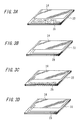
- FIGS. 1A and 1B are views showing an example of a mobile phone unit (mobile communication terminal) according to a first embodiment of the present invention, in which FIG. 1A is a plan view and FIG. 1B is a side section view;
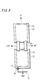
- FIG. 2 is a plan view showing an example of a state of a first circuit board, a second circuit board and a hinge used for the circuit boards, when a mobile phone unit according to the first embodiment of the present invention is fully opened;
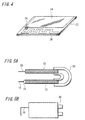
- FIGS. 3A to 3D are perspective views showing examples of a structure of a passive antenna;
- FIG. 4 is a perspective view showing a modified example in which a circuit chip is connected between a passive antenna and a GND portion of a mobile phone unit according to the first embodiment of the present invention;
- FIGS. 5A and 5B are views showing an example of a state of the first circuit, the second circuit and the hinge used for the circuit boards, when the mobile phone unit according to the first embodiment of the present invention is folded, in which FIG. 5A is a side view and FIG. 5B is a plan view;
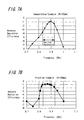
- FIGS. 6A and 6B show a comparative example, in which FIG. 6A is a plan view, and FIG. 6B is a characteristic curve of the antenna radiation efficiency;
- FIGS. 7A and 7B are characteristic curves, in which FIG. 7A shows an example of the antenna radiation efficiency in a comparative example (H=165mm), and FIG. 7B shows an example of the antenna radiation efficiency according to the first embodiment of the present invention (H=165mm);
- FIG. 8 is a characteristic curve showing examples of the antenna radiation efficiency, when the resonance frequency of the passive antenna according to the first embodiment of the present invention is a lower limit fL (lower limit communication frequency), the resonance frequency thereof is an upper limit fH and the resonance frequency thereof is an average fc of the lower limit and upper limit in the communication frequency band, respectively;
- FIG. 9 is an explanatory view in which the directions of the antenna radiation pattern are defined;
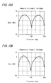
- FIGS. 10A and 10B are characteristic curves showing examples of the antenna radiation pattern in a comparative example;
- FIGS. 11A and 11B are characteristic curves, in which FIG. 11A shows an example of the antenna radiation pattern in a comparative example (H=165mm) and FIG. 11B shows an example of antenna radiation pattern according to an embodiment of the present invention (H=165mm);
- FIG. 12 is a characteristic curve which shows an example of
the antenna radiation efficiency, when a
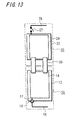
mobile phone unit 1 is folded; - FIG. 13 is a plan view showing an example of a state of the
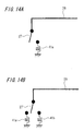
first circuit board 12 and thesecond circuit board 22, when a mobile phone unit (mobile communication terminal) according to a second embodiment of the present invention is fully opened; - FIGS. 14A and 14B are connection diagrams showing an example of the connection of a passive antenna of a mobile phone unit according to the second embodiment of the present invention;
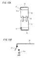
- FIGS. 15A and 15B are views showing the mobile phone unit according to the second embodiment of the present invention, in which FIG. 15A is a plan view showing a state of the casing thereof, and FIG. 15B is a connection diagram showing an example of the connection of a passive antenna in the state;
- FIGS. 16A and 16B are views showing a mobile phone unit according to the second embodiment of the present invention, in which FIG. 16A is a plan view showing a state of the casing thereof, and FIG. 16B is a connection diagram showing an example of the connection of a passive antenna in the state;
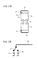
- FIGS. 17A and 17B are views showing a mobile phone unit according to the second embodiment of the present invention, in which FIG. 17A is a plan view showing a state of the casing thereof, and FIG. 17B is a connection diagram showing an example of the connection of a passive antenna in the state;
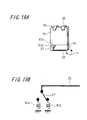
- FIGS. 18A and 18B are views showing a mobile phone unit according to the second embodiment of the present invention, in which FIG. 18A is a plan view showing a state of the casing thereof, and FIG. 18B is a connection diagram showing an example of the connection of a passive antenna in the state;
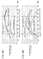
- FIGS. 19A and 19B are characteristic curves showing the antenna radiation efficiency according to the second embodiment of the present invention, in which FIG. 19A shows an example of the characteristic when a terminal is opened, and FIG. 19B shows an example thereof when the terminal is closed; and
- FIG. 20 is a plan view showing a modified example of a mobile phone unit (mobile communication terminal) according to the second embodiment of the present invention.
-
- Hereinafter, the first embodiment of the present invention will be explained with reference to FIGS. 1 to 12.
- FIGS. 1A and 1B are views showing a mobile phone unit 1 (mobile communication terminal) according to this embodiment; FIG. 1A is a plan view and FIG. 1B is side section view. A communication frequency band that the
mobile phone 1 uses for communication is predetermined in every system. The communication frequency band is from about 0.83GHz to about 0.93GHz, for example. Hereupon, the lower limit of the communication frequency band is called fL (the lower limit frequency), the upper limit thereof is called fH, and the average between the lower limit and upper limit is called fc. - The
mobile phone unit 1 includes afirst casing 10 and asecond casing 20. As shown in FIG. 1A, buttons such as a ten-key are provided in thefirst casing 10. A display is provided in thesecond casing 20. Thefirst casing 10 and thesecond casing 20 are connected by a hinge not shown in the figure. Themobile phone unit 1 can be folded by means of this hinge such that the buttons of thefirst casing 10 and the display of thesecond casing 20 are opposed to each other. In FIGS. 1A and 1B, thefirst casing 10 and thesecond casing 20 are at an angle of almost 45 degrees, and themobile phone unit 1 is recognized as being open in such state. The angle made by thefirst casing 10 and thesecond casing 20 may not almost exist in some cases. Also, there is so-called a turning type in which thesecond casing 20 is rotated clockwise or counterclockwise with respect to thefirst casing 10 and can be folded. In the following embodiments, in the case where a mobile phone unit capable of being folded is mentioned, all the types described above are included. - As shown in FIG. 1B, the
first casing 10 has afirst circuit board 12 and thesecond casing 20 has asecond circuit board 22. Thefirst circuit board 12 and thesecond circuit board 22 are connected by acircuit board hinge 30. With this, thefirst circuit board 12 and thesecond circuit board 22 can change the posture flexibly depending on the folded state of themobile phone unit 1. - FIG. 2 is a plan view showing a state of the
first circuit board 12,second circuit board 22 andcircuit board hinge 30, when themobile phone unit 1 is fully opened and thefirst casing 10 and thesecond casing 20 face almost in the same direction (when opened). - A GND (ground potential)
portion 14, apower feeding antenna 16, apower supply portion 17 and afeed point 18 are provided in thefirst circuit board 12. - The GND (ground potential)
portion 14 is a portion keeping the ground potential. For example, the portion has almost a rectangular-shaped solid circuit pattern. Thepower feeding antenna 16 is an antenna to which high frequency electric power is supplied. Thepower supply portion 17 is connected to theGND portion 14 and thepower feeding antenna 16 and supplies the high frequency electric power between theground portion 14 and thepower feeding antenna 16. Thefeed point 18 is a portion at which thepower feeding antenna 16 is connected to thefirst circuit board 12, and thepower feeding antenna 16 receives power through thefeed point 18. - A GND (ground potential)
portion 24 and apassive antenna 26 are attached to thesecond circuit board 22. - The GND (ground potential)
portion 24 is a portion keeping the ground potential. For example, the portion has almost a rectangular-shaped solid circuit pattern. Thepassive antenna 26 is an antenna to which power is not supplied. Thepassive antenna 26 is connected to theground portion 24. - Here, the whole length L = La + Lb (La: a portion parallel to the short side of the
second circuit board 22, Lb: a portion parallel to the long side of the second circuit board 22) of thepassive antenna 26 is approximately a quarter of a wavelength λ of a radio wave corresponding to the fL (lower limit frequency). In other words, L=λ/4. With such construction, thepassive antenna 26 is made to resonate at the lower limit communication frequency fL. Note that the whole length L of thepassive antenna 26 may not be λ/4 on condition that the antenna resonates at the lower limit communication frequency. - Further, the
passive antenna 26 can be provided on thesecond circuit board 22 instead of being attached to the outside of thesecond circuit board 22. The modified examples are shown in FIGS. 3A to 3D. - As shown in FIG. 3A, the
passive antenna 26 may have the circuit pattern of the shape of meanders. As shown in FIG. 3B, thepassive antenna 26 may have the circuit pattern of an approximately straight shape in which the long side portion is considerably longer than the short side portion. Further, thepassive antenna 26 may not be the circuit pattern and may be a wire as shown in FIG. 3C and may be a metal plate as shown in FIG. 3D. - In the above described examples, the
passive antenna 26 is made to resonate at the lower limit communication frequency fL by adjusting the whole length L of thepassive antenna 26. However, instead of adjusting the whole length L of thepassive antenna 26, as shown in FIG. 4, acircuit chip 25 may be connected to thepassive antenna 26 and theGND portion 24 to make thepassive antenna 26 resonate at the lower limit communication frequency fL. - FIGS. 5A and 5B show a state of the
first circuit 12,second circuit 22 andcircuit board hinge 30, when themobile phone unit 1 is folded and thefirst casing 10 and thesecond casing 20 oppose to each other; FIG. 5A is a side view and FIG. 5B is a plan view. - As shown in FIG. 5A, the
power feeding antenna 16 opposes to thepassive antenna 26. Further, thepower feeding antenna 16 is positioned at the back of thepassive antenna 26 shown in FIG. 5B, and thepower feeding antenna 16 opposes to thepassive antenna 26. Accordingly, thepower feeding antenna 16 and thepassive antenna 26 are electromagnetically coupled. - FIGS. 6A and 6B show a comparative example to be compared with a practice example of the present invention; FIG. 6A is a plan view and FIG. 6B shows the antenna radiation efficiency.
- As shown in FIG. 6A, the comparative example has no
passive antenna 26. In this case, the antenna radiation efficiency changes depending on the whole length H of the circuit board that is the sum of the length of thefirst circuit board 12 and the length of the second circuit board 22 (refer to FIG. 6B). It is recognized that H=125mm is the case with which the radiation efficiency becomes highest in the desired communication frequency band (the desired band). - In FIGS. 7A and 7B, FIG. 7A shows the antenna radiation efficiency in a comparative example (H=165mm), and FIG. 7B shows the antenna radiation efficiency in a practice example (H=165mm) of the present invention.
- As shown in FIG. 7A, the antenna radiation efficiency in the comparative example (H=165mm) is not desirable, because it becomes particularly low around the lower limit of the desired band. On the other hand, as shown in FIG. 7B, the antenna radiation efficiency in the practice example (H=165mm) of the present invention becomes almost constant within the desired band and is desirable, while the whole length H of the circuit board is the same as that of the comparative example. Hence, the antenna radiation efficiency becomes desirable in the desired band regardless of the whole length H of the circuit board according to the practice example of the present invention.
- FIG. 8 shows the antenna radiation efficiency of a
passive antenna 26 in the communication frequency band, in each of the cases where the resonance frequency thereof is a lower limit fL (lower limit communication frequency), is an upper limit fH and is an average fc of the lower limit and upper limit. As shown in FIG. 8, the antenna radiation efficiency becomes particularly low around the lower limit fL in the communication frequency band, when the resonance frequency of thepassive antenna 26 is fH and fc, which is not favorable. On the other hand, the antenna radiation efficiency becomes excellent over the whole of the desired band, when the resonance frequency of thepassive antenna 26 is fL, which is favorable. - Therefore, since the
passive antenna 26 is provided in thesecond circuit board 22 and the resonance frequency of thepassive antenna 26 is fL, the antenna radiation efficiency becomes excellent over the whole of the desired band and the desirable effectiveness can be obtained. - Here, directions are defined as shown in FIG. 9 and the antenna radiation pattern in the comparative example is shown in FIGS. 10A and 10B. It is known that the radiation pattern from the minute current element is a sine curve, and originally, the direction of maximum radiation is the side directions (90°, 270°) and should become symmetrical with the top and bottom (the directions of 0° and 180°). The case shown in FIG. 10A (H=125mm) is the original radiation pattern, and the antenna radiation efficiency is excellent (refer to FIG. 6B).
- However, depending on the whole length H of the circuit board, the phase of the high-frequency current which flows on the circuit board is reversed on the path of the current, and so the offset of the radiation occurs to make the antenna radiation pattern distorted. As a result, the direction of maximum radiation will shift upward (in the directions of 0° and 360°) from the side directions (90°, 270°). It is a case (H=165 mm) shown in FIG. 10B. In this case, the radiation characteristics (efficiency and band) becomes deteriorated by the offset of the radiation (refer to FIG. 6B). While the phase reversal generally occurs by the half-wavelength in the high frequency current, the phase reversal occurs by the length shorter than the half-wavelength when the current flows in the circuit board or the like having the width and thickness.
- In FIGS. 11A and 11B, FIG. 11A shows the antenna radiation pattern in the comparative example (H=165mm) and FIG. 11B shows the antenna radiation pattern in the practice example (H=165mm) of the present invention.
- As shown in FIG. 11A, the antenna radiation pattern in the comparative example (H=165mm) is not desirable, because the direction of maximum radiation shifts upward (in the directions of 0° and 360°). On the other hand, as shown in FIG. 11B, the practice example of the present invention (H=165mm) is desirable, because the direction of maximum radiation comes closer to the side directions (90°, 270°), while the whole length H of the circuit board is the same as that of the comparative example. Hence, according to the practice example of the present invention, the antenna radiation pattern becomes desirable regardless of the whole length H of the circuit board.
- The characteristics of the antenna when the
mobile phone unit 1 is opened have heretofore been explained, hereupon, the antenna radiation efficiency when themobile phone unit 1 is folded is shown in FIG. 12. As is obvious from FIG. 12, the antenna radiation efficiency of the practice example 1 according to the present invention is higher than that of the comparative example in the desired band. - Next, the second embodiment of the present invention will be explained with reference to FIGS. 13 to 20. Since the second embodiment is also applied to the folding type mobile phone unit 1 (the mobile communication terminal) similarly to the first embodiment, the same reference numerals are given to the same members as those in the
mobile phone unit 1 explained in the first embodiment and the detailed explanation is omitted. - FIG. 13 is a drawing of a mobile phone unit (mobile communication terminal) 1 according to this embodiment of the present invention and is a plan view showing a state of a
first circuit board 12,second circuit board 22 andcircuit board hinge 30, when themobile phone unit 1 is fully opened and afirst casing 10 and asecond casing 20 face almost in the same direction (when opened). - A GND (ground potential)
portion 14, apower feeding antenna 16, apower supply portion 17 and afeed point 18 are provided in thefirst circuit board 12. - The GND (ground potential)
portion 14 is a portion keeping the ground potential. For example, the portion has almost a rectangular-shaped solid circuit pattern. Thepower feeding antenna 16 is an antenna to which the high frequency electric power is supplied. Thepower supply portion 17 is connected to theground portion 14 and thepower feeding antenna 16 and supplies the high frequency electric power between thepower feeding antenna 16 and theGND portion 14. Thefeed point 18 is a portion at which thepower feeding antenna 16 is connected to thefirst circuit board 12, and thepower feeding antenna 16 receives power through thefeed point 18. - The
second circuit board 22 has a GND (ground potential)portion 24, and apassive antenna 26 is attached to theGND portion 24 through aswitch 27. - The GND (ground potential)
portion 24 is a portion keeping the ground potential. For example, the portion has almost a rectangular-shaped solid circuit pattern. Thepassive antenna 26 is an antenna to which power is not supplied. Thepassive antenna 26 is connected to theGND portion 24 through theswitch 27. - The
switch 27 is switched between when themobile phone unit 1 is fully opened and thefirst casing 10 and thesecond casing 20 are opened and when thefirst casing 10 and thesecond casing 20 are closed, for example. The switching of this switch is performed by the control of a control portion (not shown in the figure) which detects the states of the opening and closing of themobile phone unit 1, for example. Alternatively, a switch changed mechanically in accordance with the opening and closing operations of themobile phone unit 1 may be used. - Similarly to the first embodiment, the whole length of the
passive antenna 26 is preferable to be approximately a quarter of a wavelength λ of the radio wave corresponding to the fL (lower limit frequency). In other words, L=λ/4. With such construction, thepassive antenna 26 is made to resonate at the lower limit communication frequency fL. Note that the whole length L of thepassive antenna 26 may not be λ/4 on condition that the antenna resonates at the lower limit communication frequency. - Further, similarly to the first embodiment, the
passive antenna 26 may be provided on thesecond circuit board 22 instead of being attached to the outside of thesecond circuit board 22 and may have various shapes as shown in FIGS. 3A to 3D, for example. - When the
GND portion 24 and thepassive antenna 26 are connected through theswitch 27, circuit components (a coil, resistance, capacitor and so on) made of chip components and the like may be attached. Specifically, as shown in FIG. 14A for example, acoil 41a (thiscoil 41a has the inductance value of 33nH or 30nH, for example) is connected between theGND portion 24 and thepassive antenna 26, when theswitch 27 is closed. Further, thepassive antenna 26 is made not to connect to thecoil 41a and theGND portion 24, when the switch is opened. - Further, as shown in FIG. 14B for example, a switch connected to the
passive antenna 26 is provided as a switch 27' which can be switched from one side to the other side, and acoil 41a is connected between theGND portion 24 and thepassive antenna 26 when the switch changes to one side, and acoil 41b is connected between theGND portion 24 and thepassive antenna 26 when the switch changes to the other side. Thecoil 41a has the inductance value of 33nH, for example, and thecoil 41b has the inductance value of 30nH, for example. The inductance components formed of a chip component are used as thecoils - FIGS. 15A and 15B and FIGS. 16A and 16B are drawings which show an example of a state of the
passive antenna 26 when themobile phone unit 1 is opened (FIGS. 15A and 15B), and show an example of a state of thepassive antenna 26 when themobile phone unit 1 is closed (FIGS. 16A and 16B), in the case where the connection configuration shown in FIG. 14A is employed. - When the
mobile phone unit 1 is opened as shown in FIG. 15A, theswitch 27 is in an open state as shown in FIG. 15B and thepassive antenna 26 is in a state of being separated from thecoil 41a and the GND 24 (that is, a state of being separated from the circuit board inside the second casing 20). - When the
mobile phone unit 1 is closed as shown in FIG. 16A, theswitch 27 is in a closed state as shown in FIG 16B and thepassive antenna 26 is in a state of being connected to theGND portion 24 through thecoil 41a. - FIGS. 17A and 17B and FIGS. 18A and 18B are drawings which show an example of a state of the
passive antenna 26 when themobile phone unit 1 is opened (FIGS. 17A and 17B), and show an example of a state of thepassive antenna 26 when themobile phone unit 1 is closed (FIGS. 18A and 18B), in the case where the connection configuration shown in FIG. 14B is employed. - When the
mobile phone unit 1 is opened as shown in FIG. 17A, the switch 27' is in a state of being connected to one side as shown in FIG. 17B and thepassive antenna 26 is in a state of being connected to theGND portion 24 through thecoil 41a. - When the
mobile phone unit 1 is closed as shown in FIG. 18A, the switch 27' is in a state of being connected to the other side as shown in FIG. 18B and thepassive antenna 26 is in a state of being connected to theGND portion 24 through thecoil 41b. - With such construction, when the
mobile phone unit 1 is closed, the characteristics as the mobile communication terminal becomes excellent, because the electromagnetic coupling e is generated between theantenna 16 on thefirst casing 10 side and thepassive antenna 26 on thesecond casing 20 side as shown in FIG. 16A or 18A. Further, when themobile phone unit 1 is opened, the characteristics in the open state can be improved, because thepassive antenna 26 is in a state of being separated (FIGS. 15A and 15B) or is in another connection state (FIG. 17A and 17B). - FIGS. 19A and 19B are characteristic curves showing an example of the antenna radiation efficiency of a practice example (practice example 2) according to the second embodiment of the present invention. Here, FIG. 19A shows an example of the characteristic in the frequency band for the wireless communication when a
mobile phone unit 1 is opened, and FIG. 19B shows an example of the characteristic in the frequency band for the wireless communication when amobile phone unit 1 is closed. - In this practice example, with respect to each state of the
mobile phone unit 1, the characteristics in three states are compared: the state in which the coil with the inductance value a (here, 33nH) is connected between thepassive antenna 26 and the GND portion, the state in which the coil with the inductance value b (here, 30nH) is connected between thepassive antenna 26 and the GND portion, and the state in which thepassive antenna 26 is separated from the GND portion. - As shown in FIG. 19A, when the
mobile phone unit 1 is opened, the characteristics obtained in the case of using the inductance value b and in the case of not connecting to the passive antenna are superior to the characteristic obtained in the case of using the inductance value a, in almost all the frequency band for the communication. - Further, as shown in FIG. 19B, when the
mobile phone unit 1 is closed, the characteristics obtained in the case of using the inductance value a and in the case of using the inductance value b are superior to the characteristic obtained in the case of not connecting to the passive antenna, in almost all the frequency band for the communication. - Therefore, for example, both in the examples of FIGS. 15A and 15B and FIGS. 16A and 16B, excellent communication characteristics are obtained, in which when the terminal is opened, the passive antenna is not connected and in which when the terminal is closed, the passive antenna is connected to the GND portion through the coil of the inductance value a or b.
- Further, for example, both in the examples of FIGS. 17A and 17B and FIGS. 18A and 18B, excellent communication characteristics are obtained, in which when the terminal is opened, the passive antenna is connected to the GND portion through the coil of the inductance value b and in which when the terminal is closed, the passive antenna is connected to the GND portion through the coil of the inductance value a.
- Note that the radiation efficiency shown in FIG. 19 changes depending on various factors regarding a structure such as the size of a circuit board to which an antenna is connected, and the state in which characteristic is more favorable depends on the structure. Also, regarding the inductance values, the values mentioned above are examples.
- Further, in the second embodiment heretofore explained, the
switch 27 or 27' to switch the connection of the passive antenna is provided at the end portion where the GDN portion of the antenna is connected, however the switch may be provided in the middle of the passive antenna and a part of the passive antenna is separated depending on the state of the terminal. - Specifically, as shown in FIG. 20 for example, when a
switch 28 is provided in the middle of thepassive antenna 26 and the mobile phone unit is opened, about the half of the tip side of thepassive antenna 26 is separated from the GND portion by making theswitch 28 into the open state, and only the remaining half is connected to the GND portion. Then, when the mobile phone unit is closed, the whole of thepassive antenna 26 is made to connect to the GND portion by making theswitch 28 into the closed state. The circuit components such as a coil and so on may be connected in series to theswitch 28. - With the above construction, the antenna characteristic in each state of the mobile phone unit can be improved.
Claims (15)
- A mobile communication terminal comprising:a first casing including a power feeding antenna to which power is supplied anda second casing connected to said first casing, whereinsaid second casing includes a passive antenna to which power is not supplied and which resonates at approximately the lower limit communication frequency in a communication frequency band used for communication.
- The mobile communication terminal according to claim 1, wherein
the electrical length of said passive antenna is a quarter of a wavelength of a radio wave corresponding to said lower limit communication frequency. - The mobile communication terminal according to claim 1, wherein
said first casing and said second casing can be folded to be opposed to each other. - The mobile communication terminal according to claim 3, wherein
said power feeding antenna and said passive antenna are electromagnetically coupled when folded. - The mobile communication terminal according to claim 1, wherein
said first casing has a first circuit board to which said power feeding antenna is connected,
said second casing has a second circuit board in which said passive antenna is provided, and
power is supplied between said power feeding antenna and a ground potential of said first circuit board. - The mobile communication terminal according to claim 5, wherein
said passive antenna has a circuit pattern provided on said second circuit board. - The mobile communication terminal according to claim 6, wherein
said circuit pattern has the shape of meanders. - The mobile communication terminal according to claim 6, wherein
said circuit pattern has an approximately straight shape. - The mobile communication terminal according to claim 5, wherein
said passive antenna has a wire provided on said second circuit board. - The mobile communication terminal according to claim 5, wherein
said passive antenna has a metal plate provided on said second circuit board. - The mobile communication terminal according to claim 5, wherein
said second casing has a circuit member which is connected to said passive antenna and a ground potential of said second circuit board and which makes said passive antenna resonate at said lower limit communication frequency. - A mobile communication terminal comprising:a first casing including a power feeding antenna to which power is supplied anda second casing connected to said first casing, whereinsaid second casing has a passive antenna selectively connected.
- The mobile communication terminal according to claim 12, wherein
said first casing and said second casing can be folded to be opposed to each other and
a connection state of said passive antenna is changed between the state in which said first casing and said second casing are folded and the state in which the both are not folded. - The mobile communication terminal according to claim 13, wherein
said power feeding antenna and said passive antenna are electromagnetically coupled when folded. - The mobile communication terminal according to claim 12, wherein
said first casing has a first circuit board connected to said power feeding antenna,
said second casing has a second circuit board in which said passive antenna is provided, and
power is supplied between said power feeding antenna and a ground potential of said first circuit board.
Priority Applications (1)
| Application Number | Priority Date | Filing Date | Title |
|---|---|---|---|
| EP07024685A EP1898490B1 (en) | 2003-09-18 | 2004-09-15 | Mobile communication terminal |
Applications Claiming Priority (3)
| Application Number | Priority Date | Filing Date | Title |
|---|---|---|---|
| JP2003326689 | 2003-09-18 | ||
| JP2003326689 | 2003-09-18 | ||
| PCT/JP2004/013878 WO2005029638A1 (en) | 2003-09-18 | 2004-09-15 | Mobile communication terminal |
Related Child Applications (1)
| Application Number | Title | Priority Date | Filing Date |
|---|---|---|---|
| EP07024685A Division EP1898490B1 (en) | 2003-09-18 | 2004-09-15 | Mobile communication terminal |
Publications (3)
| Publication Number | Publication Date |
|---|---|
| EP1555716A1 true EP1555716A1 (en) | 2005-07-20 |
| EP1555716A4 EP1555716A4 (en) | 2006-03-08 |
| EP1555716B1 EP1555716B1 (en) | 2008-03-12 |
Family
ID=34372828
Family Applications (2)
| Application Number | Title | Priority Date | Filing Date |
|---|---|---|---|
| EP04773360A Expired - Fee Related EP1555716B1 (en) | 2003-09-18 | 2004-09-15 | Mobile communication terminal |
| EP07024685A Expired - Fee Related EP1898490B1 (en) | 2003-09-18 | 2004-09-15 | Mobile communication terminal |
Family Applications After (1)
| Application Number | Title | Priority Date | Filing Date |
|---|---|---|---|
| EP07024685A Expired - Fee Related EP1898490B1 (en) | 2003-09-18 | 2004-09-15 | Mobile communication terminal |
Country Status (4)
| Country | Link |
|---|---|
| EP (2) | EP1555716B1 (en) |
| JP (1) | JP4426531B2 (en) |
| DE (2) | DE602004012377T2 (en) |
| WO (1) | WO2005029638A1 (en) |
Cited By (5)
| Publication number | Priority date | Publication date | Assignee | Title |
|---|---|---|---|---|
| WO2007118824A2 (en) * | 2006-04-18 | 2007-10-25 | Palm, Inc. | Mobile terminal with a monopole like antenna |
| EP2372834A1 (en) * | 2008-12-26 | 2011-10-05 | Panasonic Corporation | Portable wireless apparatus |
| US8854276B2 (en) | 2008-12-25 | 2014-10-07 | Kyocera Corporation | Portable terminal |
| US20170110786A1 (en) * | 2015-10-14 | 2017-04-20 | Microsoft Technology Licensing, Llc | Self-adaptive antenna systems for electronic devices having multiple form factors |
| US11888239B2 (en) | 2019-02-22 | 2024-01-30 | Huawei Technologies Co., Ltd. | Antenna apparatus and electronic device |
Families Citing this family (3)
| Publication number | Priority date | Publication date | Assignee | Title |
|---|---|---|---|---|
| US7696928B2 (en) | 2006-02-08 | 2010-04-13 | Hong Kong Applied Science And Technology Research Institute Co., Ltd. | Systems and methods for using parasitic elements for controlling antenna resonances |
| US7616158B2 (en) | 2006-05-26 | 2009-11-10 | Hong Kong Applied Science And Technology Research Institute Co., Ltd. | Multi mode antenna system |
| JP6462247B2 (en) | 2014-06-26 | 2019-01-30 | Necプラットフォームズ株式会社 | ANTENNA DEVICE, RADIO COMMUNICATION DEVICE, AND BAND ADJUSTMENT METHOD |
Citations (9)
| Publication number | Priority date | Publication date | Assignee | Title |
|---|---|---|---|---|
| US5572223A (en) * | 1994-07-21 | 1996-11-05 | Motorola, Inc. | Apparatus for multi-position antenna |
| EP0860897A1 (en) * | 1996-09-11 | 1998-08-26 | Matsushita Electric Industrial Co., Ltd. | Antenna system |
| US5905473A (en) * | 1997-03-31 | 1999-05-18 | Resound Corporation | Adjustable array antenna |
| US5943021A (en) * | 1998-08-03 | 1999-08-24 | Ericsson Inc. | Swivel antenna with parasitic tuning |
| US6239753B1 (en) * | 1996-04-05 | 2001-05-29 | Omron Corporation | Transmitter-and-receiver device |
| US6246374B1 (en) * | 2000-04-06 | 2001-06-12 | Motorola, Inc. | Passive flip radiator for antenna enhancement |
| WO2002019671A1 (en) * | 2000-08-28 | 2002-03-07 | In4Tel Ltd. | Apparatus and method for enhancing low-frequency operation of mobile communication antennas |
| EP1258943A1 (en) * | 2001-05-08 | 2002-11-20 | Mitsubishi Denki Kabushiki Kaisha | Foldable portable telephone using one of the shieldings as a second antenna |
| EP1306922A2 (en) * | 2001-10-24 | 2003-05-02 | Matsushita Electric Industrial Co., Ltd. | Antenna structure, methof of using antenna structure and communication device |
Family Cites Families (7)
| Publication number | Priority date | Publication date | Assignee | Title |
|---|---|---|---|---|
| JP3767030B2 (en) * | 1996-09-09 | 2006-04-19 | 三菱電機株式会社 | Foldable wireless communication device |
| JP3783447B2 (en) * | 1998-03-18 | 2006-06-07 | 株式会社村田製作所 | Antenna device and portable radio using the same |
| SE9801381D0 (en) * | 1998-04-20 | 1998-04-20 | Allgon Ab | Ground extension arrangement for coupling to ground means in an antenna system, and an antenna system and a mobile radio device having such ground arrangement |
| JP2003037415A (en) * | 2001-07-25 | 2003-02-07 | Matsushita Electric Ind Co Ltd | Portable radio unit |
| JP3502071B2 (en) * | 2001-08-08 | 2004-03-02 | 松下電器産業株式会社 | Radio antenna device |
| JP2003273620A (en) * | 2002-03-19 | 2003-09-26 | Sony Corp | Portable electronic equipment |
| JP2003347815A (en) * | 2002-05-23 | 2003-12-05 | Nec Corp | Mobile radio equipment |
-
2004
- 2004-09-15 JP JP2005514113A patent/JP4426531B2/en not_active Expired - Fee Related
- 2004-09-15 WO PCT/JP2004/013878 patent/WO2005029638A1/en active IP Right Grant
- 2004-09-15 EP EP04773360A patent/EP1555716B1/en not_active Expired - Fee Related
- 2004-09-15 DE DE602004012377T patent/DE602004012377T2/en active Active
- 2004-09-15 EP EP07024685A patent/EP1898490B1/en not_active Expired - Fee Related
- 2004-09-15 DE DE200460026946 patent/DE602004026946D1/en active Active
Patent Citations (9)
| Publication number | Priority date | Publication date | Assignee | Title |
|---|---|---|---|---|
| US5572223A (en) * | 1994-07-21 | 1996-11-05 | Motorola, Inc. | Apparatus for multi-position antenna |
| US6239753B1 (en) * | 1996-04-05 | 2001-05-29 | Omron Corporation | Transmitter-and-receiver device |
| EP0860897A1 (en) * | 1996-09-11 | 1998-08-26 | Matsushita Electric Industrial Co., Ltd. | Antenna system |
| US5905473A (en) * | 1997-03-31 | 1999-05-18 | Resound Corporation | Adjustable array antenna |
| US5943021A (en) * | 1998-08-03 | 1999-08-24 | Ericsson Inc. | Swivel antenna with parasitic tuning |
| US6246374B1 (en) * | 2000-04-06 | 2001-06-12 | Motorola, Inc. | Passive flip radiator for antenna enhancement |
| WO2002019671A1 (en) * | 2000-08-28 | 2002-03-07 | In4Tel Ltd. | Apparatus and method for enhancing low-frequency operation of mobile communication antennas |
| EP1258943A1 (en) * | 2001-05-08 | 2002-11-20 | Mitsubishi Denki Kabushiki Kaisha | Foldable portable telephone using one of the shieldings as a second antenna |
| EP1306922A2 (en) * | 2001-10-24 | 2003-05-02 | Matsushita Electric Industrial Co., Ltd. | Antenna structure, methof of using antenna structure and communication device |
Non-Patent Citations (1)
| Title |
|---|
| See also references of WO2005029638A1 * |
Cited By (8)
| Publication number | Priority date | Publication date | Assignee | Title |
|---|---|---|---|---|
| WO2007118824A2 (en) * | 2006-04-18 | 2007-10-25 | Palm, Inc. | Mobile terminal with a monopole like antenna |
| WO2007118824A3 (en) * | 2006-04-18 | 2008-04-10 | Benq Mobile Gmbh & Co Ohg | Mobile terminal with a monopole like antenna |
| US8854276B2 (en) | 2008-12-25 | 2014-10-07 | Kyocera Corporation | Portable terminal |
| EP2372834A1 (en) * | 2008-12-26 | 2011-10-05 | Panasonic Corporation | Portable wireless apparatus |
| EP2372834A4 (en) * | 2008-12-26 | 2012-07-25 | Panasonic Corp | Portable wireless apparatus |
| US20170110786A1 (en) * | 2015-10-14 | 2017-04-20 | Microsoft Technology Licensing, Llc | Self-adaptive antenna systems for electronic devices having multiple form factors |
| US10193213B2 (en) * | 2015-10-14 | 2019-01-29 | Microsoft Technology Licensing, Llc | Self-adaptive antenna systems for electronic devices having multiple form factors |
| US11888239B2 (en) | 2019-02-22 | 2024-01-30 | Huawei Technologies Co., Ltd. | Antenna apparatus and electronic device |
Also Published As
| Publication number | Publication date |
|---|---|
| JP4426531B2 (en) | 2010-03-03 |
| DE602004012377T2 (en) | 2009-03-12 |
| JPWO2005029638A1 (en) | 2006-11-30 |
| DE602004026946D1 (en) | 2010-06-10 |
| EP1898490B1 (en) | 2010-04-28 |
| WO2005029638A1 (en) | 2005-03-31 |
| EP1555716A4 (en) | 2006-03-08 |
| DE602004012377D1 (en) | 2008-04-24 |
| EP1555716B1 (en) | 2008-03-12 |
| EP1898490A1 (en) | 2008-03-12 |
Similar Documents
| Publication | Publication Date | Title |
|---|---|---|
| KR101025680B1 (en) | Antenna device and portable radio communication terminal | |
| JP3562512B2 (en) | Surface mounted antenna and communication device provided with the antenna | |
| US7760150B2 (en) | Antenna assembly and wireless unit employing it | |
| US7825861B2 (en) | Radio module | |
| KR101232557B1 (en) | Mobile radio device | |
| US7787915B2 (en) | Folding type portable wireless unit | |
| US7589673B2 (en) | Antenna and mobile wireless equipment using the same | |
| KR100993439B1 (en) | Antenna arrangement | |
| EP2160796B1 (en) | An antenna arrangement | |
| EP2198478B1 (en) | An antenna arrangement, a method for manufacturing an antenna arrangement and a printed wiring board for use in an antenna arrangement | |
| JP4440243B2 (en) | Mobile device | |
| WO2011067944A1 (en) | Portable radio | |
| KR20070053125A (en) | Folded dipole antenna device and mobile radio terminal | |
| EP1703587A1 (en) | Antenna and portable radio communication unit | |
| EP2302734B1 (en) | Short-side direction slide type radio apparatus | |
| EP1555716B1 (en) | Mobile communication terminal | |
| JP2008294635A (en) | Antenna unit and portable radio apparatus | |
| JP4049185B2 (en) | Portable radio | |
| US20120062429A1 (en) | Portable radio | |
| JP4925937B2 (en) | ANTENNA DEVICE AND PORTABLE RADIO DEVICE | |
| EP1708304A1 (en) | Multi-band mobile phone antenna | |
| CN102931470A (en) | Multi-part wireless device |
Legal Events
| Date | Code | Title | Description |
|---|---|---|---|
| PUAI | Public reference made under article 153(3) epc to a published international application that has entered the european phase |
Free format text: ORIGINAL CODE: 0009012 |
|
| 17P | Request for examination filed |
Effective date: 20050520 |
|
| AK | Designated contracting states |
Kind code of ref document: A1 Designated state(s): AT BE BG CH CY CZ DE DK EE ES FI FR GB GR HU IE IT LI LU MC NL PL PT RO SE SI SK TR |
|
| AX | Request for extension of the european patent |
Extension state: AL HR LT LV MK |
|
| RIC1 | Information provided on ipc code assigned before grant |
Ipc: H01Q 9/42 19680901ALI20051201BHEP Ipc: H01Q 1/38 19680901AFI20051201BHEP Ipc: H01Q 21/30 19680901ALI20051201BHEP |
|
| A4 | Supplementary search report drawn up and despatched |
Effective date: 20060119 |
|
| DAX | Request for extension of the european patent (deleted) | ||
| RBV | Designated contracting states (corrected) |
Designated state(s): DE FR GB |
|
| RIN1 | Information on inventor provided before grant (corrected) |
Inventor name: MATSUMOTO, HIROYUKI Inventor name: SHOJI, HIDEAKI Inventor name: SAWAMURA, MASATOSHI Inventor name: KOZAKAI, OSAMU |
|
| 17Q | First examination report despatched |
Effective date: 20060509 |
|
| RIN1 | Information on inventor provided before grant (corrected) |
Inventor name: MATSUMOTO, HIROYUKI Inventor name: SAWAMURA, MASATOSHI Inventor name: SHOJI, HIDEAKI Inventor name: KOZAKAI, OSAMUC/O SONY ERICSSON MOB. COMMUNICATION |
|
| GRAP | Despatch of communication of intention to grant a patent |
Free format text: ORIGINAL CODE: EPIDOSNIGR1 |
|
| GRAS | Grant fee paid |
Free format text: ORIGINAL CODE: EPIDOSNIGR3 |
|
| GRAA | (expected) grant |
Free format text: ORIGINAL CODE: 0009210 |
|
| AK | Designated contracting states |
Kind code of ref document: B1 Designated state(s): DE FR GB |
|
| REG | Reference to a national code |
Ref country code: GB Ref legal event code: FG4D |
|
| REF | Corresponds to: |
Ref document number: 602004012377 Country of ref document: DE Date of ref document: 20080424 Kind code of ref document: P |
|
| ET | Fr: translation filed | ||
| PLBE | No opposition filed within time limit |
Free format text: ORIGINAL CODE: 0009261 |
|
| STAA | Information on the status of an ep patent application or granted ep patent |
Free format text: STATUS: NO OPPOSITION FILED WITHIN TIME LIMIT |
|
| 26N | No opposition filed |
Effective date: 20081215 |
|
| REG | Reference to a national code |
Ref country code: FR Ref legal event code: PLFP Year of fee payment: 12 |
|
| PGFP | Annual fee paid to national office [announced via postgrant information from national office to epo] |
Ref country code: GB Payment date: 20150917 Year of fee payment: 12 Ref country code: DE Payment date: 20150922 Year of fee payment: 12 |
|
| PGFP | Annual fee paid to national office [announced via postgrant information from national office to epo] |
Ref country code: FR Payment date: 20150922 Year of fee payment: 12 |
|
| REG | Reference to a national code |
Ref country code: DE Ref legal event code: R119 Ref document number: 602004012377 Country of ref document: DE |
|
| GBPC | Gb: european patent ceased through non-payment of renewal fee |
Effective date: 20160915 |
|
| REG | Reference to a national code |
Ref country code: FR Ref legal event code: ST Effective date: 20170531 |
|
| PG25 | Lapsed in a contracting state [announced via postgrant information from national office to epo] |
Ref country code: GB Free format text: LAPSE BECAUSE OF NON-PAYMENT OF DUE FEES Effective date: 20160915 Ref country code: FR Free format text: LAPSE BECAUSE OF NON-PAYMENT OF DUE FEES Effective date: 20160930 Ref country code: DE Free format text: LAPSE BECAUSE OF NON-PAYMENT OF DUE FEES Effective date: 20170401 |