EP1555445A2 - Arrangement for fixing objects to a wall - Google Patents
Arrangement for fixing objects to a wall Download PDFInfo
- Publication number
- EP1555445A2 EP1555445A2 EP04027038A EP04027038A EP1555445A2 EP 1555445 A2 EP1555445 A2 EP 1555445A2 EP 04027038 A EP04027038 A EP 04027038A EP 04027038 A EP04027038 A EP 04027038A EP 1555445 A2 EP1555445 A2 EP 1555445A2
- Authority
- EP
- European Patent Office
- Prior art keywords
- arrangement
- hook
- use position
- component
- eye
- Prior art date
- Legal status (The legal status is an assumption and is not a legal conclusion. Google has not performed a legal analysis and makes no representation as to the accuracy of the status listed.)
- Granted
Links
Images


Classifications
-
- B—PERFORMING OPERATIONS; TRANSPORTING
- B60—VEHICLES IN GENERAL
- B60R—VEHICLES, VEHICLE FITTINGS, OR VEHICLE PARTS, NOT OTHERWISE PROVIDED FOR
- B60R7/00—Stowing or holding appliances inside vehicle primarily intended for personal property smaller than suit-cases, e.g. travelling articles, or maps
- B60R7/08—Disposition of racks, clips, holders, containers or the like for supporting specific articles
- B60R7/10—Disposition of racks, clips, holders, containers or the like for supporting specific articles for supporting hats, clothes or clothes hangers
-
- B—PERFORMING OPERATIONS; TRANSPORTING
- B60—VEHICLES IN GENERAL
- B60N—SEATS SPECIALLY ADAPTED FOR VEHICLES; VEHICLE PASSENGER ACCOMMODATION NOT OTHERWISE PROVIDED FOR
- B60N3/00—Arrangements or adaptations of other passenger fittings, not otherwise provided for
- B60N3/02—Arrangements or adaptations of other passenger fittings, not otherwise provided for of hand grips or straps
- B60N3/023—Arrangements or adaptations of other passenger fittings, not otherwise provided for of hand grips or straps movable
-
- B—PERFORMING OPERATIONS; TRANSPORTING
- B60—VEHICLES IN GENERAL
- B60P—VEHICLES ADAPTED FOR LOAD TRANSPORTATION OR TO TRANSPORT, TO CARRY, OR TO COMPRISE SPECIAL LOADS OR OBJECTS
- B60P7/00—Securing or covering of load on vehicles
- B60P7/06—Securing of load
- B60P7/08—Securing to the vehicle floor or sides
- B60P7/0807—Attachment points
Definitions
- the present invention relates to an arrangement for attachment of objects a wall according to the preamble of claim 1.
- Hooks for hanging objects, jackets or coats, in the interior a motor vehicle in the area above the side windows between the A and B pillars and / or the B and C columns, integrated in handles, are for example from DE 199 55 621 A1, DE 201 01 541 U1 and DE 101 19 604 C1.
- a hook device for attachment of Shopping bags and the like are known in the footwell area of the passenger are turned off to secure them from falling over even in sharp turns.
- the Hook device is about 180 degrees between a non-use position and a Swivel position of use.
- hooks are known in the trunk of Station wagons and limousines are arranged to hang items there as well can.
- a disadvantage of these arrangements of hooks proves that this Hooks are usually designed as separate components, which adds extra Production costs for the provision of a hook arise.
- As an example of such Hooks can serve EP 1 132 257 A2 and DE 94 05 306 U1.
- a coat hook in a motor vehicle is known, which is from the position of use in the non-use position in the headliner or in the Side paneling can be inserted in a straight line and has a very small installation space needed.
- a disadvantage may be the relatively large installation depth of this embodiment.
- Fold-out eyelets for lashing objects in motor vehicles are for example from DE 35 22 393 A1, DE 295 00 242 U1 and EP 1 123 838 A2 known. Like the hooks mentioned above, the lashing eyes are also separate Components executed.
- the core of the invention according to claim 1 is therefore known hooks and for Known eyelets combine to form a component.
- a preferred Embodiment of the invention is by integration of hook and eye in a single component on the one hand avoided that the hook or the eyelet as additional part is executed.
- the space requirement in the interior of the Motor vehicle reduced. Important in this context is the reduction the installation effort.
- this component can be alternately in a position of use and pivot a non-use position each one of its areas.
- the hook or the eyelet used in one and the same place is, the component according to the invention can be expediently either in the Use position of the hook, the use position of the eyelet or in the Swivel non-use position of the component, in which the hook and the eyelet in their non-use position.
- hook and eye the is called the hook-shaped and the eye-shaped area, formed by individual parts, which together form the component. Both parts are independent in Use position and non-use position preferably in hinge-like Arrangement swiveling.
- the advantage of this embodiment is that you have the can use hook and eye-shaped area at the same time.
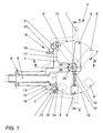
- FIG. 1 to 3 is a wall 1, for example, part of a side panel may be shown with a pot-like receptacle 2.
- a cup-like receptacle 2 In the cup-like receptacle 2 is an arrangement 3 installed.
- This, the actual invention performing arrangement. 3 comprises a holder 4 which is fixed by means of a screw 5 in the shell 6, and a Component 7.
- the screw 5 is advantageously as a socket screw, such as Torx or Allen, trained, but it can also be a cross or slotted screw.
- the component 7 consists of a hook-shaped region 8 and a loop-shaped Area 9.
- the hook-shaped area 8 and the eye-shaped area 9 are in this Embodiment jointly pivotable about a horizontally extending Mounted pivot axis 10 and are located with respect to the pivot axis 10 diametrically across from. If the component 7 as in this embodiment at a more or less vertical wall 1 is mounted, there is the hook-shaped area. 8 above and the eye-shaped area 9 with each other on both sides of the common Pivot axis 10.
- the hook-shaped portion 8 pivots along the pivoting circle 11 and the eye-shaped area 9 along the pivoting circle 12 in each case at least three different locking positions: located in a first locking position Both the hook-shaped area 8 and the eye-shaped area 9 in the Non-use position (shown with a continuous outline).
- the component 7 forms in this non-use position with a more or less flat conclusion the wall 1.
- the hook-shaped portion 8th in its use position reproduced at 8 ', the eye-shaped area 9 in contrast, in his at 9 'indicated non-use position.
- a third Arresting position is finally the hook-shaped portion 8 in the Non-use position 8 "and the eye-shaped portion 9 in its use position 9 ".
- the latter two positions are represented by a dashed outline.
- the two areas 8 and 9 a form single component 7, that are rigidly connected to each other
- the two Areas 8 and 9 in another embodiment not shown here also be formed by individual parts, so that the component 7 is then in two parts as it were. These two parts are then independent of each other about the pivot axis 10th pivotable, so that both in the use position or the Can be located in non-use position.
- a handle or the like must be present in order to for example, to be able to pull out the hook.
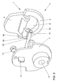
- the holder 4 has a hole 13 for the screw 5 behind the eye-shaped area 9, because a fitter then the screw 5 with a Screwdriver or with an Allen key through an opening 14th tighten in the eye-shaped area 9 and so can fix the holder 4 on the shell 6.
- This opening 14 here forms the eyelet itself.
- the holder 4 has in the lower Area, that is in the eye-shaped area 9, a recess 15, and the screw fifth has a screw head 16, wherein advantageously the recess 15 so is dimensioned so that they can completely accommodate the screw head 16, so that the Top of the screw head 16 terminates with the surface 17 of the holder 4.
- the inventive arrangement 3 in the holder 4 a Clip connection 18, which clings into the wall 1.
- the clip connection 18 is in This embodiment of a locking pin 19, which is integral with the holder 10th is connected, and locking lugs 20 in the wall. 1
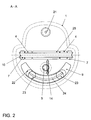
- stop buffer 21 and 22 are clipped in the holder 4 yet.
- the stop buffer 21 is round and the stop buffer 22 has an arcuate shape, actually a circular ring section (see in particular Figure 2).
- the arcuate stop buffer 22 has two plugs 23, the engage in the holder 4, and an arcuate recess groove 24, which here too has the shape of a circular ring section.
- FIGS. 4 and 5 the arrangement 3 according to the invention is in each case one Exploded view shown.
- Figure 4 shows the arrangement from the front, so from Vehicle interior seen from and Figure 5 from the rear, so from the side in the built-in state is no longer visible.
- the stop buffer 22 in the Figures 2 to 3 is arcuate, is the stop buffer 22 'in the figure 4th round.
- the Verraster 25 has two locking lugs 28 and 28 ' and a recessed groove 29. In the non-use position of both the hook-shaped portion 8 and the eye-shaped portion 9 engages the latch 26th in the recessed groove 29, the locking lug 28 in the recessed groove 27 and the locking lug 28 ' into the recessed groove 27 '.
- In the use position 8 'of the hook-shaped area snaps the locking lug 26 'in the recessed groove 29 and in the position of use 9 "of eyelet-shaped area, the locking lug 26 "in the recessed groove 29 a.
- the hook-shaped portion 8 is similar to the DE already mentioned 197 30 562 A1 in particular for hanging bags, so that they are filled Condition does not fall over.
- the eye-shaped area 9 is particularly suitable for hooking of luggage nets, rubber banners, or similar fastening or Load securing equipment.
- the arrangement according to the invention thus offers a cost-effective and practical Choice between two different attachment or Holding means in one and the same place.
Abstract
Description
Die vorliegende Erfindung betrifft eine Anordnung zur Befestigung von Gegenständen an
einer Wand gemäß dem Oberbegriffs des Patentanspruchs 1.The present invention relates to an arrangement for attachment of objects
a wall according to the preamble of
Haken für die Aufhängung von Gegenständen, Jacken oder Mänteln, im Innenraum eines Kraftfahrzeuges im Bereich oberhalb der Seitenscheiben zwischen der A- und B-Säule und/oder der B- und C-Säule, integriert in Haltegriffe, sind beispielsweise aus der DE 199 55 621 A1, DE 201 01 541 U1 und DE 101 19 604 C1 bekannt.Hooks for hanging objects, jackets or coats, in the interior a motor vehicle in the area above the side windows between the A and B pillars and / or the B and C columns, integrated in handles, are for example from DE 199 55 621 A1, DE 201 01 541 U1 and DE 101 19 604 C1.
Weiterhin ist aus der DE 101 55 941 A1 eine Anordnung eines Hakens für die Aufhängung von Gegenständen in einem Kraftfahrzeug bekannt, wobei der Haken in eine Klappe eines Faches zur Aufbewahrung von Gegenständen integriert ist.Furthermore, from DE 101 55 941 A1 an arrangement of a hook for the Suspension of objects known in a motor vehicle, wherein the hook in a flap of a compartment for storing objects is integrated.
Aus der DE 197 30 562 A1 ist eine Hakeneinrichtung zur Befestigung von Einkaufstaschen und dergleichen bekannt, die im Fußraumbereich des Beifahrers abgestellt sind, um diese vor dem Umfallen auch in scharfen Kurven zu sichern. Die Hakeneinrichtung ist um ca. 180 Grad zwischen einer Nichtgebrauchsstellung und einer Gebrauchsstellung schwenkbar.From DE 197 30 562 A1 a hook device for attachment of Shopping bags and the like are known in the footwell area of the passenger are turned off to secure them from falling over even in sharp turns. The Hook device is about 180 degrees between a non-use position and a Swivel position of use.
Weiterhin sind aus dem Stand der Technik Haken bekannt, die in dem Kofferraum von
Kombis und Limousinen angeordnet sind, um auch dort Gegenstände aufhängen zu
können. Als nachteilig bei diesen Anordnungen von Haken erweist sich, dass diese
Haken in der Regel als separate Bauteile ausgeführt sind, wodurch zusätzliche
Fertigungskosten für das Vorsehen eines Haken entstehen. Als Beispiel für solche
Haken können die EP 1 132 257 A2 und DE 94 05 306 U1 dienen.Furthermore, from the prior art hooks are known in the trunk of
Station wagons and limousines are arranged to hang items there as well
can. A disadvantage of these arrangements of hooks proves that this
Hooks are usually designed as separate components, which adds extra
Production costs for the provision of a hook arise. As an example of such
Hooks can serve
Aus der DE 199 13 745 A1 ist ein Kleiderhaken in einem Kraftfahrzeug bekannt, der sich von der Gebrauchslage in die Nichtgebrauchslage in den Dachhimmel oder in die Seitenverkleidung gradlinig hineinschieben läßt und der einen sehr kleinen Einbauraum benötigt. Nachteilig kann an dieser Ausführungsform die relativ große Einbautiefe sein.From DE 199 13 745 A1 a coat hook in a motor vehicle is known, which is from the position of use in the non-use position in the headliner or in the Side paneling can be inserted in a straight line and has a very small installation space needed. A disadvantage may be the relatively large installation depth of this embodiment.
Ausklappbare Ösen zum Verzurren von Gegenständen in Kraftfahrzeugen sind beispielsweise aus der DE 35 22 393 A1, DE 295 00 242 U1 und EP 1 123 838 A2 bekannt. Ebenso wie die oben genannten Haken sind auch die Verzurrösen als separate Bauteile ausgeführt.Fold-out eyelets for lashing objects in motor vehicles are for example from DE 35 22 393 A1, DE 295 00 242 U1 and EP 1 123 838 A2 known. Like the hooks mentioned above, the lashing eyes are also separate Components executed.
Es ist Aufgabe der Erfindung, eine an einer Wand vorzusehende Anordnung zur Befestigung von Gegenständen zu schaffen, die die Wahlmöglichkeit zwischen mindestens zwei unterschiedlichen Befestigungs- beziehungsweise Haltemitteln an ein und der selben Stelle bietet.It is an object of the invention to provide an on a wall arrangement for Attachment of objects to create the choice between at least two different fastening or holding means to a and the same place offers.
Die Aufgabe wird erfindungsgemäß mit den Merkmalen des Anspruchs 1 gelöst.
Vorteilhafte Ausführungen beschreiben die Unteransprüche.The object is achieved with the features of
Aus dem Stand der Technik sind zwar verschiedene Haken und verschiedene Ösen bekannt, jedoch sind dies immer separate Bauteile an unterschiedlichen Einbaustellen. Oft wird aber an ein und der selben Stelle einmal ein Haken und ein anderes Mal eine Öse, gegebenenfalls beide gleichzeitig, gebraucht. Wenn zum Beispiel im Kofferraum ein Haken gebraucht wird und nur eine Öse vorhanden ist, nützt ein Haken an einer anderen Stelle im Fahrzeug wenig.From the prior art, although different hooks and different eyelets However, these are always separate components at different installation sites. Often, however, at one and the same point, there is a catch and another time Eyelet, possibly both at the same time, used. If, for example, in the trunk Hook is needed and only one eyelet is available, a hook on another Place in the vehicle little.
Der Kern der Erfindung gemäß Anspruch 1 ist es daher, für sich bekannte Haken und für
sich bekannte Ösen zu einem Bauteil zusammenzufassen. Bei einer bevorzugten
Ausführungsform der Erfindung wird durch Integration von Haken und Öse in ein
einziges Bauteil zum einen vermieden, dass der Haken beziehungsweise die Öse als
zusätzliches Teil ausgeführt ist. Zum anderen wird der Platzbedarf im Innenraum des
Kraftfahrzeugs reduziert. Wichtig in diesem Zusammenhang ist auch die Reduzierung
des Montageaufwandes.The core of the invention according to
Vorteilhafterweise läßt sich dieses Bauteil wechselweise in eine Gebrauchsposition und eine Nichtgebrauchsposition jeweils eines seiner Bereiche verschwenken. Da wie schon beschrieben, entweder der Haken oder die Öse an ein und derselben Stelle gebraucht wird, läßt sich zweckmäßigerweise das erfindungsgemäße Bauteil entweder in die Gebrauchsposition des Hakens, die Gebrauchsposition der Öse oder in die Nichtgebrauchsposition des Bauteils verschwenken, in der sich der Haken und die Öse in ihrer Nichtgebrauchsposition befinden.Advantageously, this component can be alternately in a position of use and pivot a non-use position each one of its areas. There you are described, either the hook or the eyelet used in one and the same place is, the component according to the invention can be expediently either in the Use position of the hook, the use position of the eyelet or in the Swivel non-use position of the component, in which the hook and the eyelet in their non-use position.
Dagegen werden in einer anderen Ausführungsform der Erfindung Haken und Öse, das heißt der hakenförmige und der ösenförmige Bereich, durch individuelle Teile gebildet, die zusammen das Bauteil bilden. Beide Teile sind unabhängig voneinander in Gebrauchsposition und Nichtgebrauchsposition vorzugsweise in scharnierartiger Anordnung schwenkbar. Der Vorteil an dieser Ausführungsform ist, dass man den haken- und ösenförmigen Bereich gleichzeitig benutzen kann.In contrast, in another embodiment of the invention hook and eye, the is called the hook-shaped and the eye-shaped area, formed by individual parts, which together form the component. Both parts are independent in Use position and non-use position preferably in hinge-like Arrangement swiveling. The advantage of this embodiment is that you have the can use hook and eye-shaped area at the same time.
Weitere Merkmale und Vorteile der vorliegenden Erfindung werden deutlich anhand der nachfolgenden Beschreibung bevorzugter Ausführungsbeispiele unter Bezugnahme auf die beiliegenden Abbildungen. Darin zeigen
Figur 1- eine Ansicht einer erfindungsgemäßen Anordnung,
Figur 2- den Schnitt A-A durch die erfindungsgemäße Anordnung,
Figur 3- den Schnitt B-B durch die erfindungsgemäße Anordnung,
Figur 4- eine perspektivische Explosionsdarstellung von vorne,
Figur 5- eine Explosionsdarstellung von der Einbauseite gesehen,
Figur 6 und 7- ein weiteres Aufführungsbeispiel der erfindungsgemäßen Anordnung.
- FIG. 1
- a view of an arrangement according to the invention,
- FIG. 2
- the section AA through the inventive arrangement,
- FIG. 3
- the section BB by the arrangement according to the invention,
- FIG. 4
- an exploded perspective view from the front,
- FIG. 5
- an exploded view seen from the installation side,
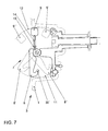
- FIGS. 6 and 7
- another performance example of the arrangement according to the invention.
In den Figuren 1 bis 3 ist eine Wand 1, die zum Beispiel ein Teil einer Seitenverkleidung
sein kann, mit einer topfartigen Aufnahme 2 dargestellt. In die topfartige Aufnahme 2 ist
eine Anordnung 3 eingebaut. Diese, die eigentliche Erfindung darstellende Anordnung 3
umfaßt einen Halter 4, der mit Hilfe einer Schraube 5 im Rohbau 6 befestigt ist, und ein
Bauteil 7. Die Schraube 5 ist vorteilhafterweise als Innenkantschraube, wie zum Beispiel
Torx oder Inbus, ausgebildet, sie kann aber auch eine Kreuz- oder Schlitzschraube sein.
Das Bauteil 7 besteht aus einem hakenförmigen Bereich 8 und einem ösenförmigen
Bereich 9. Der hakenförmige Bereich 8 und der ösenförmige Bereich 9 sind in diesem
Ausführungsbeispiel gemeinsam schwenkbar um eine horizontal verlaufende
Schwenkachse 10 gelagert und liegen sich bezüglich der Schwenkachse 10 diametral
gegenüber. Wenn das Bauteil 7 wie in diesem Ausführungsbeispiel an einer mehr oder
weniger senkrechten Wand 1 montiert ist, befindet sich der hakenförmige Bereich 8
oberhalb und der ösenförmige Bereich 9 untereinander beiderseits der gemeinsamen
Schwenkachse 10. Der hakenförmige Bereich 8 schwenkt entlang des Schwenkkreises
11 und der ösenförmigen Bereich 9 entlang des Schwenkkreises 12 in jeweils
mindestens drei verschiedene Arretierpositionen: In einer ersten Arretierposition befindet
sich sowohl der hakenförmige Bereich 8 als auch der ösenförmige Bereich 9 in der
Nichtgebrauchsposition (dargestellt mit einer durchgehenden Umrißlinie). Das Bauteil 7
bildet in dieser Nichtgebrauchsposition einen mehr oder weniger flachen Abschluß mit
der Wand 1. In einer anderen Arretierposition befindet sich der hakenförmige Bereich 8
in seiner bei 8' wiedergegebenen Gebrauchsposition, der ösenförmige Bereich 9
dagegen in seiner bei 9' angedeuteten Nichtgebrauchsposition. In einer dritten
Arretierposition befindet sich schließlich der hakenförmige Bereich 8 in der
Nichtgebrauchsposition 8" und der ösenförmige Bereich 9 in seiner Gebrauchsposition
9". Die letzteren beiden Positionen sind durch eine gestrichelte Umrißlinie dargestellt.In Figures 1 to 3 is a
Während in dem beschriebenen Ausführungsbeispiel die beiden Bereiche 8 und 9 ein
einziges Bauteil 7 bilden, also starr miteinander verbunden sind, können die beiden
Bereiche 8 und 9 in einem anderen hier nicht dargestellten Ausführungsbeispiel auch
durch individuelle Teile gebildet sein, so dass das Bauteil 7 dann gleichsam zweiteilig ist.
Diese beiden Teile sind dann unabhängig voneinander um die Schwenkachse 10
schwenkbar, so dass sich beide in der Gebrauchsposition beziehungsweise der
Nichtgebrauchsposition befinden können. Während man in dem Ausführungsbeispiel der
Figuren 1 bis 3 den gewünschten Bereich 8 oder 9 durch Druck auf den der
Schwenkachse 10 gegenüberliegenden Bereich 8 beziehungsweise 9 ausklappen kann,
muß bei dieser Ausführungsform ein Griff oder ähnliches vorhanden sein, um
beispielsweise den Haken herausziehen zu können.While in the described embodiment, the two
Vorteilhafterweise weist der Halter 4 ein Loch 13 für die Schraube 5 hinter dem
ösenförmigen Bereich 9 auf, weil ein Monteur dann die Schraube 5 mit einem
Schraubendreher beziehungsweise mit einem Innenkantschlüssel durch eine Öffnung 14
im ösenförmigen Bereich 9 anziehen und so den Halter 4 am Rohbau 6 befestigen kann.
Diese Öffnung 14 bildet hier auch die Öse an sich. Der Halter 4 besitzt im unteren
Bereich, das heißt im ösenförmigen Bereich 9, eine Vertiefung 15, und die Schraube 5
weist einen Schraubenkopf 16 auf, wobei vorteilhafterweise die Vertiefung 15 so
dimensioniert ist, dass sie den Schraubenkopf 16 komplett aufnehmen kann, so dass die
Oberseite des Schraubenkopfs 16 mit der Oberfläche 17 des Halters 4 abschließt.Advantageously, the
Um das Loch 13 für die Montage genau vor der Öffnung für die Schraube 5 zu
positionieren, weist die erfindungsgemäße Anordnung 3 im Halter 4 eine
Clipsverbindung 18 auf, die in die Wand 1 einclipst. Die Clipsverbindung 18 besteht in
diesem Ausführungsbeispiel aus einem Rastzapfen 19, der einstückig mit dem Halter 10
verbunden ist, und Rastnasen 20 in der Wand 1.To the
Da das Bauteil 7 und der Halter 4 beide vorteilhafterweise aus einem harten Werkstoff
gefertigt sind, sind in dem Halter 4 noch zwei Anschlagpuffer 21 und 22 eingeclipst. In
der Nichtgebrauchsposition 8" des hakenförmigen Bereichs liegt dieser am
Anschlagpuffer 21 an, in der Nichtgebrauchsposition 9' des ösenförmigen Bereichs liegt
dieser am Anschlagpuffer 22 an. Der Anschlagpuffer 21 ist rund und der Anschlagpuffer
22 hat eine bogenförmige Form, genaugenommen die eines Kreisringabschnitts (siehe
insbesondere Figur 2). Der bogenförmige Anschlagpuffer 22 weist zwei Pfropfen 23, die
in den Halter 4 einrasten, und eine bogenförmige Vertiefungsrille 24 auf, die hier auch
die Form eines Kreisringabschnitts hat.Since the
In den Figuren 4 und 5 ist die erfindungsgemäße Anordnung 3 jeweils in einer
Explosionsdarstellung gezeigt. Figur 4 zeigt die Anordnung von vorne, also vom
Fahrzeuginneren aus gesehen und Figur 5 von hinten, also von der Seite, die im
eingebauten Zustand nicht mehr sichtbar ist. Während der Anschlagpuffer 22 in den
Figuren 2 bis 3 bogenförmig ausgebildet ist, ist der Anschlagpuffer 22' in der Figur 4
rund.In FIGS. 4 and 5, the
Weil das harte Bauteil 7 schlecht mit dem ebenfalls harten Halter 4 verrasten kann, wird
in den mittleren Bereich der Schwenkachse 10 ein Verraster 25 aus einem weicheren
und nachgiebigeren Material montiert, der mit dem Bauteil 7 zusammen um die
Schwenkachse 10 schwenkt. Um in den drei verschiedenen Arretierpositionen verrasten
zu können, befinden sich am Halter 4 drei Rastnasen 26, 26' und 26" und zwei
Vertiefungsrillen 27 und 27' (Figur 4). Der Verraster 25 weist zwei Rastnasen 28 und 28'
und eine Vertiefungsrille 29 auf. In der Nichtgebrauchsstellung sowohl des
hakenförmigen Bereichs 8 als auch des ösenförmigen Bereichs 9 rastet die Rastnase 26
in die Vertiefungsrille 29, die Rastnase 28 in die Vertiefungsrille 27 und die Rastnase 28'
in die Vertiefungsrille 27' ein. In der Gebrauchsstellung 8' des hakenförmigen Bereichs
rastet die Rastnase 26' in die Vertiefungsrille 29 und in der Gebrauchsstellung 9" des
ösenförmigen Bereichs die Rastnase 26" in die Vertiefungsrille 29 ein.Because the
Der hakenförmige Bereich 8 eignet sich ähnlich wie in der schon eingangs erwähnten DE
197 30 562 A1 insbesondere zum Einhängen von Taschen, damit diese im befüllten
Zustand nicht umfallen. Der ösenförmige Bereich 9 eignet sich besonders zum Einhaken
von Gepäcknetzen, Gummispannern, oder ähnlichen Befestigungs- oder
Ladegutsicherungseinrichtungen.The hook-shaped
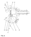
Während im Ausführungsbeispiel der Figuren 1 bis 3 die Anordnung 3 so in der Wand 1
montiert wird, dass sich innerhalb des Bauteils 7 der hakenförmige Bereich 8 oben und
der ösenförmige Bereich 9 unten befindet, ist in den beiden verschiedenen
Ausführungsbeispielen der Figuren 6 und 7 der ösenförmige Bereich 9 oben und der
hakenförmige Bereich 8 unten. Der hakenförmige Bereich 8 weist in der Figur 6 einen
nach außen gebogenen Haken 30 und in der Figur 7 einen nach innen gebogenen
Haken 30' auf. Diese ungekehrte Montage in diesem Ausführungsbeispiel im Vergleich
zum Ausführungsbeispiel der Figuren 1 bis 3 rührt daher, weil im Ausführungsbeispiel
der Figuren 1 bis 3 der Haken durch Abklappen des hakenförmigen Bereichs 8 nach
außen bebildet wird und beim vorliegenden Ausführungsbeispielen der Figuren 6 und 7
die Haken 30 und 30' schon fertig ausgebildet sind.While in the embodiment of Figures 1 to 3, the
Die erfindungsgemäße Anordnung bietet somit eine kostengünstige und praktische Wahlmöglichkeit zwischen zwei unterschiedlichen Befestigungs- beziehungsweise Haltemitteln an ein und der selben Stelle. The arrangement according to the invention thus offers a cost-effective and practical Choice between two different attachment or Holding means in one and the same place.
- 11
- Wandwall
- 22
- topfartige Aufnahmecup-like intake
- 33
- Anordnungarrangement
- 44
- Halterholder
- 55
- Schraubescrew
- 66
- Rohbaushell
- 77
- Bauteilcomponent
- 88th
- hakenförmiger Bereichhook-shaped area
- 8',8th',
-
Gebrauchsposition des hakenförmigen Bereichs 8Use position of the hook-shaped
area 8 - 8"8th"
-
Nichtgebrauchsposition des hakenförmigen Bereichs 8Non-use position of the hook-shaped
portion 8 - 99
- ösenförmiger Bereicheyelet-shaped area
- 9'9 '
-
Nichtgebrauchsposition des ösenförmigen Bereichs 9Non-use position of the loop-shaped
area 9 - 9"9 "
-
Gebrauchsposition des ösenförmigen Bereichs 9Use position of the eye-shaped
area 9 - 1010
- Schwenkachseswivel axis
- 1111
- Schwenkkreisswing circle
- 1212
- Schwenkkreisswing circle
- 1313
-
Loch im Halter 4Hole in the
holder 4 - 1414
-
Öffnung im ösenförmigen Bereich 9Opening in the eye-shaped
area 9 - 1515
-
Vertiefung des Halters 4Deepening of the
holder 4 - 1616
- Schraubenkopfscrew head
- 1717
-
Oberfläche des Halters 4Surface of the
holder 4 - 1818
- Clipsverbindungclip connection
- 1919
- Rastzapfenlatching pin
- 2020
- Rastnasenlocking lugs
- 21, 22, 22'21, 22, 22 '
- Anschlagpufferbuffer
- 2323
- PfropfenGraft
- 2424
- Vertiefungsrillerecessed groove
- 2525
- VerrasterVerraster
- 26, 26', 26"26, 26 ', 26 "
- Rastnaselocking lug
- 27,27'27.27 '
- Vertiefungsrillerecessed groove
- 28, 28'28, 28 '
- Rastnaselocking lug
- 2929
- Vertiefungsrillerecessed groove
- 30,30'30.30 '
- Hakenhook
Claims (14)
Applications Claiming Priority (2)
| Application Number | Priority Date | Filing Date | Title |
|---|---|---|---|
| DE102004002050 | 2004-01-15 | ||
| DE200410002050 DE102004002050A1 (en) | 2004-01-15 | 2004-01-15 | Arrangement for fixing objects to a wall |
Publications (3)
| Publication Number | Publication Date |
|---|---|
| EP1555445A2 true EP1555445A2 (en) | 2005-07-20 |
| EP1555445A3 EP1555445A3 (en) | 2006-10-04 |
| EP1555445B1 EP1555445B1 (en) | 2013-05-29 |
Family
ID=34609556
Family Applications (1)
| Application Number | Title | Priority Date | Filing Date |
|---|---|---|---|
| EP20040027038 Not-in-force EP1555445B1 (en) | 2004-01-15 | 2004-11-13 | Arrangement for fixing objects to a wall |
Country Status (2)
| Country | Link |
|---|---|
| EP (1) | EP1555445B1 (en) |
| DE (1) | DE102004002050A1 (en) |
Cited By (1)
| Publication number | Priority date | Publication date | Assignee | Title |
|---|---|---|---|---|
| EP1754629A3 (en) * | 2005-08-15 | 2007-12-26 | YMOS GmbH | Device for securing loads in vehicle |
Families Citing this family (1)
| Publication number | Priority date | Publication date | Assignee | Title |
|---|---|---|---|---|
| CZ2010536A3 (en) | 2010-07-07 | 2012-01-18 | Škoda Auto a. s. | Removable suspension means of baggage compartment |
Citations (5)
| Publication number | Priority date | Publication date | Assignee | Title |
|---|---|---|---|---|
| US2222950A (en) * | 1940-06-07 | 1940-11-26 | Harry Rubin | Assist strap for vehicles |
| DE2911197B1 (en) * | 1979-03-22 | 1980-10-02 | Happich Gmbh Gebr | Handle, in particular a bow-like handle for the interior of motor vehicles |
| US5676508A (en) * | 1995-04-03 | 1997-10-14 | Weicht; Gary Lee | Multi-function tie-down device |
| US6076233A (en) * | 1998-05-27 | 2000-06-20 | Honda Giken Kogyo Kabushiki Kaisha | Grab rail and hook assembly for a vehicle |
| JP2004010017A (en) * | 2002-06-11 | 2004-01-15 | Kanto Auto Works Ltd | Hooked grip |
Family Cites Families (4)
| Publication number | Priority date | Publication date | Assignee | Title |
|---|---|---|---|---|
| DE7916926U1 (en) * | 1977-12-14 | 1979-09-20 | Baelter, Bror G., Orsa (Schweden) | Hook device |
| SE507623C3 (en) * | 1992-02-18 | 1998-08-10 | Wiklund Henry & Co | Lifting hook with safety lock and possibility for automatic load release |
| FR2739152B1 (en) * | 1995-09-22 | 1997-12-05 | Wichard | SAFETY CARABINER |
| EP0948913A1 (en) * | 1998-04-08 | 1999-10-13 | Luciano Rosa | Locking device for the releasable connection of two parts |
-
2004
- 2004-01-15 DE DE200410002050 patent/DE102004002050A1/en not_active Withdrawn
- 2004-11-13 EP EP20040027038 patent/EP1555445B1/en not_active Not-in-force
Patent Citations (5)
| Publication number | Priority date | Publication date | Assignee | Title |
|---|---|---|---|---|
| US2222950A (en) * | 1940-06-07 | 1940-11-26 | Harry Rubin | Assist strap for vehicles |
| DE2911197B1 (en) * | 1979-03-22 | 1980-10-02 | Happich Gmbh Gebr | Handle, in particular a bow-like handle for the interior of motor vehicles |
| US5676508A (en) * | 1995-04-03 | 1997-10-14 | Weicht; Gary Lee | Multi-function tie-down device |
| US6076233A (en) * | 1998-05-27 | 2000-06-20 | Honda Giken Kogyo Kabushiki Kaisha | Grab rail and hook assembly for a vehicle |
| JP2004010017A (en) * | 2002-06-11 | 2004-01-15 | Kanto Auto Works Ltd | Hooked grip |
Non-Patent Citations (1)
| Title |
|---|
| PATENT ABSTRACTS OF JAPAN Bd. 2003, Nr. 12, 5. Dezember 2003 (2003-12-05) & JP 2004 010017 A (KANTO AUTO WORKS LTD), 15. Januar 2004 (2004-01-15) * |
Cited By (1)
| Publication number | Priority date | Publication date | Assignee | Title |
|---|---|---|---|---|
| EP1754629A3 (en) * | 2005-08-15 | 2007-12-26 | YMOS GmbH | Device for securing loads in vehicle |
Also Published As
| Publication number | Publication date |
|---|---|
| DE102004002050A1 (en) | 2005-08-04 |
| EP1555445B1 (en) | 2013-05-29 |
| EP1555445A3 (en) | 2006-10-04 |
Similar Documents
| Publication | Publication Date | Title |
|---|---|---|
| DE60126547T2 (en) | Molded part for motor vehicles and associated fastening element | |
| DE602004008564T2 (en) | Vehicle side wall storage container arrangement | |
| DE102017118623A1 (en) | HANDLEBAR WITH MOUNTING SUPPORTS IN DIFFERENT HEIGHTS FOR VEHICLE DOOR ASSEMBLY. | |
| DE10303733A1 (en) | Integrated vehicle cupboard system | |
| DE102013214337A1 (en) | APPAREL HOOK AND PROTECTION DEVICE ASSEMBLY FOR VEHICLES | |
| DE102017221265A1 (en) | Armrest with cup holder arrangement | |
| DE10062137B4 (en) | Burglar-proof trunk lock | |
| DE19948647B4 (en) | Vehicle rear construction | |
| EP1674336B1 (en) | Net for securing load in a vehicle | |
| DE60026740T2 (en) | FASTENING DEVICE FOR REMOVABLE MOUNTING OF A TABLE | |
| EP0586842B1 (en) | Stowing appliance for the inside of a vehicle | |
| DE102009025087A1 (en) | Hatchback-handle structure for opening and/or closing hatchback in hatchback panel of e.g. caravan, has decoration unit provided with surface, so that opening stands in connection with exterior when housing is coupled with decoration unit | |
| EP1555445B1 (en) | Arrangement for fixing objects to a wall | |
| DE102016214724A1 (en) | Armrest for a motor vehicle seat | |
| DE102017206462B4 (en) | SYSTEM FOR FIXING A COVER TO A LUGGAGE TANK | |
| EP1123838B1 (en) | Tie-down device, especially for a loading space in a motor vehicle | |
| DE10236072A1 (en) | Attachment system for motor vehicle has at least one rail mounted on vehicle to bound channel to which suspension head for accessory can be removably attached; rail is mounted in passenger compartment. | |
| DE10253881A1 (en) | Cover for outer aperture in motor vehicle body is of plastic, and has journals on inside to lock into apertures, hook with grip unit, and captive strap | |
| DE102019111672B4 (en) | DELIVERY STORAGE BAG FOR ONE VEHICLE | |
| DE4336591C2 (en) | Assembly of three components that are positively connected by clip connections | |
| DE102021113002A1 (en) | CUP HOLDER DEVICE | |
| DE19859655A1 (en) | Covering construction for motor car rear threshold | |
| DE102015208748A1 (en) | Storage compartment with a lid | |
| DE102014207721A1 (en) | Arrangement for attaching a warning triangle to a vehicle wall | |
| EP1092613A2 (en) | Exterior frame member for a vehicle |
Legal Events
| Date | Code | Title | Description |
|---|---|---|---|
| PUAI | Public reference made under article 153(3) epc to a published international application that has entered the european phase |
Free format text: ORIGINAL CODE: 0009012 |
|
| AK | Designated contracting states |
Kind code of ref document: A2 Designated state(s): AT BE BG CH CY CZ DE DK EE ES FI FR GB GR HU IE IS IT LI LU MC NL PL PT RO SE SI SK TR |
|
| AX | Request for extension of the european patent |
Extension state: AL HR LT LV MK YU |
|
| PUAL | Search report despatched |
Free format text: ORIGINAL CODE: 0009013 |
|
| AK | Designated contracting states |
Kind code of ref document: A3 Designated state(s): AT BE BG CH CY CZ DE DK EE ES FI FR GB GR HU IE IS IT LI LU MC NL PL PT RO SE SI SK TR |
|
| AX | Request for extension of the european patent |
Extension state: AL HR LT LV MK YU |
|
| RIC1 | Information provided on ipc code assigned before grant |
Ipc: B60P 7/08 20060101ALI20060831BHEP Ipc: F16B 45/00 20060101ALI20060831BHEP Ipc: B60N 3/02 20060101ALI20060831BHEP Ipc: B60R 7/10 20060101AFI20060831BHEP |
|
| 17P | Request for examination filed |
Effective date: 20070404 |
|
| AKX | Designation fees paid |
Designated state(s): AT BE BG CH CY CZ DE DK EE ES FI FR GB GR HU IE IS IT LI LU MC NL PL PT RO SE SI SK TR |
|
| RAP1 | Party data changed (applicant data changed or rights of an application transferred) |
Owner name: VOLKSWAGEN AKTIENGESELLSCHAFT |
|
| GRAP | Despatch of communication of intention to grant a patent |
Free format text: ORIGINAL CODE: EPIDOSNIGR1 |
|
| GRAS | Grant fee paid |
Free format text: ORIGINAL CODE: EPIDOSNIGR3 |
|
| GRAA | (expected) grant |
Free format text: ORIGINAL CODE: 0009210 |
|
| AK | Designated contracting states |
Kind code of ref document: B1 Designated state(s): AT BE BG CH CY CZ DE DK EE ES FI FR GB GR HU IE IS IT LI LU MC NL PL PT RO SE SI SK TR |
|
| REG | Reference to a national code |
Ref country code: GB Ref legal event code: FG4D Free format text: NOT ENGLISH |
|
| REG | Reference to a national code |
Ref country code: CH Ref legal event code: EP |
|
| REG | Reference to a national code |
Ref country code: AT Ref legal event code: REF Ref document number: 614164 Country of ref document: AT Kind code of ref document: T Effective date: 20130615 |
|
| REG | Reference to a national code |
Ref country code: IE Ref legal event code: FG4D Free format text: LANGUAGE OF EP DOCUMENT: GERMAN |
|
| REG | Reference to a national code |
Ref country code: DE Ref legal event code: R096 Ref document number: 502004014198 Country of ref document: DE Effective date: 20130725 |
|
| PG25 | Lapsed in a contracting state [announced via postgrant information from national office to epo] |
Ref country code: ES Free format text: LAPSE BECAUSE OF FAILURE TO SUBMIT A TRANSLATION OF THE DESCRIPTION OR TO PAY THE FEE WITHIN THE PRESCRIBED TIME-LIMIT Effective date: 20130909 Ref country code: SI Free format text: LAPSE BECAUSE OF FAILURE TO SUBMIT A TRANSLATION OF THE DESCRIPTION OR TO PAY THE FEE WITHIN THE PRESCRIBED TIME-LIMIT Effective date: 20130529 Ref country code: SE Free format text: LAPSE BECAUSE OF FAILURE TO SUBMIT A TRANSLATION OF THE DESCRIPTION OR TO PAY THE FEE WITHIN THE PRESCRIBED TIME-LIMIT Effective date: 20130529 Ref country code: GR Free format text: LAPSE BECAUSE OF FAILURE TO SUBMIT A TRANSLATION OF THE DESCRIPTION OR TO PAY THE FEE WITHIN THE PRESCRIBED TIME-LIMIT Effective date: 20130830 Ref country code: IS Free format text: LAPSE BECAUSE OF FAILURE TO SUBMIT A TRANSLATION OF THE DESCRIPTION OR TO PAY THE FEE WITHIN THE PRESCRIBED TIME-LIMIT Effective date: 20130929 Ref country code: FI Free format text: LAPSE BECAUSE OF FAILURE TO SUBMIT A TRANSLATION OF THE DESCRIPTION OR TO PAY THE FEE WITHIN THE PRESCRIBED TIME-LIMIT Effective date: 20130529 Ref country code: PT Free format text: LAPSE BECAUSE OF FAILURE TO SUBMIT A TRANSLATION OF THE DESCRIPTION OR TO PAY THE FEE WITHIN THE PRESCRIBED TIME-LIMIT Effective date: 20130930 |
|
| REG | Reference to a national code |
Ref country code: NL Ref legal event code: VDEP Effective date: 20130529 |
|
| PG25 | Lapsed in a contracting state [announced via postgrant information from national office to epo] |
Ref country code: BG Free format text: LAPSE BECAUSE OF FAILURE TO SUBMIT A TRANSLATION OF THE DESCRIPTION OR TO PAY THE FEE WITHIN THE PRESCRIBED TIME-LIMIT Effective date: 20130829 Ref country code: PL Free format text: LAPSE BECAUSE OF FAILURE TO SUBMIT A TRANSLATION OF THE DESCRIPTION OR TO PAY THE FEE WITHIN THE PRESCRIBED TIME-LIMIT Effective date: 20130529 |
|
| PG25 | Lapsed in a contracting state [announced via postgrant information from national office to epo] |
Ref country code: CZ Free format text: LAPSE BECAUSE OF FAILURE TO SUBMIT A TRANSLATION OF THE DESCRIPTION OR TO PAY THE FEE WITHIN THE PRESCRIBED TIME-LIMIT Effective date: 20130529 Ref country code: SK Free format text: LAPSE BECAUSE OF FAILURE TO SUBMIT A TRANSLATION OF THE DESCRIPTION OR TO PAY THE FEE WITHIN THE PRESCRIBED TIME-LIMIT Effective date: 20130529 Ref country code: DK Free format text: LAPSE BECAUSE OF FAILURE TO SUBMIT A TRANSLATION OF THE DESCRIPTION OR TO PAY THE FEE WITHIN THE PRESCRIBED TIME-LIMIT Effective date: 20130529 Ref country code: EE Free format text: LAPSE BECAUSE OF FAILURE TO SUBMIT A TRANSLATION OF THE DESCRIPTION OR TO PAY THE FEE WITHIN THE PRESCRIBED TIME-LIMIT Effective date: 20130529 |
|
| PG25 | Lapsed in a contracting state [announced via postgrant information from national office to epo] |
Ref country code: NL Free format text: LAPSE BECAUSE OF FAILURE TO SUBMIT A TRANSLATION OF THE DESCRIPTION OR TO PAY THE FEE WITHIN THE PRESCRIBED TIME-LIMIT Effective date: 20130529 Ref country code: RO Free format text: LAPSE BECAUSE OF FAILURE TO SUBMIT A TRANSLATION OF THE DESCRIPTION OR TO PAY THE FEE WITHIN THE PRESCRIBED TIME-LIMIT Effective date: 20130529 Ref country code: IT Free format text: LAPSE BECAUSE OF FAILURE TO SUBMIT A TRANSLATION OF THE DESCRIPTION OR TO PAY THE FEE WITHIN THE PRESCRIBED TIME-LIMIT Effective date: 20130529 |
|
| PLBE | No opposition filed within time limit |
Free format text: ORIGINAL CODE: 0009261 |
|
| STAA | Information on the status of an ep patent application or granted ep patent |
Free format text: STATUS: NO OPPOSITION FILED WITHIN TIME LIMIT |
|
| 26N | No opposition filed |
Effective date: 20140303 |
|
| BERE | Be: lapsed |
Owner name: VOLKSWAGEN A.G. Effective date: 20131130 |
|
| REG | Reference to a national code |
Ref country code: DE Ref legal event code: R097 Ref document number: 502004014198 Country of ref document: DE Effective date: 20140303 |
|
| REG | Reference to a national code |
Ref country code: CH Ref legal event code: PL |
|
| PG25 | Lapsed in a contracting state [announced via postgrant information from national office to epo] |
Ref country code: CH Free format text: LAPSE BECAUSE OF NON-PAYMENT OF DUE FEES Effective date: 20131130 Ref country code: MC Free format text: LAPSE BECAUSE OF FAILURE TO SUBMIT A TRANSLATION OF THE DESCRIPTION OR TO PAY THE FEE WITHIN THE PRESCRIBED TIME-LIMIT Effective date: 20130529 Ref country code: LI Free format text: LAPSE BECAUSE OF NON-PAYMENT OF DUE FEES Effective date: 20131130 |
|
| REG | Reference to a national code |
Ref country code: IE Ref legal event code: MM4A |
|
| PG25 | Lapsed in a contracting state [announced via postgrant information from national office to epo] |
Ref country code: BE Free format text: LAPSE BECAUSE OF NON-PAYMENT OF DUE FEES Effective date: 20131130 |
|
| PG25 | Lapsed in a contracting state [announced via postgrant information from national office to epo] |
Ref country code: IE Free format text: LAPSE BECAUSE OF NON-PAYMENT OF DUE FEES Effective date: 20131113 |
|
| REG | Reference to a national code |
Ref country code: AT Ref legal event code: MM01 Ref document number: 614164 Country of ref document: AT Kind code of ref document: T Effective date: 20131113 |
|
| PG25 | Lapsed in a contracting state [announced via postgrant information from national office to epo] |
Ref country code: AT Free format text: LAPSE BECAUSE OF NON-PAYMENT OF DUE FEES Effective date: 20131113 |
|
| PG25 | Lapsed in a contracting state [announced via postgrant information from national office to epo] |
Ref country code: CY Free format text: LAPSE BECAUSE OF FAILURE TO SUBMIT A TRANSLATION OF THE DESCRIPTION OR TO PAY THE FEE WITHIN THE PRESCRIBED TIME-LIMIT Effective date: 20130529 Ref country code: TR Free format text: LAPSE BECAUSE OF FAILURE TO SUBMIT A TRANSLATION OF THE DESCRIPTION OR TO PAY THE FEE WITHIN THE PRESCRIBED TIME-LIMIT Effective date: 20130529 |
|
| PG25 | Lapsed in a contracting state [announced via postgrant information from national office to epo] |
Ref country code: LU Free format text: LAPSE BECAUSE OF NON-PAYMENT OF DUE FEES Effective date: 20131113 Ref country code: HU Free format text: LAPSE BECAUSE OF FAILURE TO SUBMIT A TRANSLATION OF THE DESCRIPTION OR TO PAY THE FEE WITHIN THE PRESCRIBED TIME-LIMIT; INVALID AB INITIO Effective date: 20041113 |
|
| REG | Reference to a national code |
Ref country code: FR Ref legal event code: PLFP Year of fee payment: 12 |
|
| REG | Reference to a national code |
Ref country code: FR Ref legal event code: PLFP Year of fee payment: 13 |
|
| REG | Reference to a national code |
Ref country code: DE Ref legal event code: R081 Ref document number: 502004014198 Country of ref document: DE Owner name: AUDI AG, DE Free format text: FORMER OWNER: VOLKSWAGEN AG, 38440 WOLFSBURG, DE |
|
| REG | Reference to a national code |
Ref country code: FR Ref legal event code: PLFP Year of fee payment: 14 |
|
| PGFP | Annual fee paid to national office [announced via postgrant information from national office to epo] |
Ref country code: MT Payment date: 20180924 Year of fee payment: 7 |
|
| PGFP | Annual fee paid to national office [announced via postgrant information from national office to epo] |
Ref country code: DE Payment date: 20191130 Year of fee payment: 16 |
|
| PGFP | Annual fee paid to national office [announced via postgrant information from national office to epo] |
Ref country code: FR Payment date: 20191126 Year of fee payment: 16 |
|
| GBPC | Gb: european patent ceased through non-payment of renewal fee |
Effective date: 20191113 |
|
| PG25 | Lapsed in a contracting state [announced via postgrant information from national office to epo] |
Ref country code: GB Free format text: LAPSE BECAUSE OF NON-PAYMENT OF DUE FEES Effective date: 20191113 |
|
| REG | Reference to a national code |
Ref country code: DE Ref legal event code: R119 Ref document number: 502004014198 Country of ref document: DE |
|
| PG25 | Lapsed in a contracting state [announced via postgrant information from national office to epo] |
Ref country code: FR Free format text: LAPSE BECAUSE OF NON-PAYMENT OF DUE FEES Effective date: 20201130 |
|
| PG25 | Lapsed in a contracting state [announced via postgrant information from national office to epo] |
Ref country code: DE Free format text: LAPSE BECAUSE OF NON-PAYMENT OF DUE FEES Effective date: 20210601 |