EP1536660A2 - Communication system, communication units, and method of ambience listening thereto - Google Patents
Communication system, communication units, and method of ambience listening thereto Download PDFInfo
- Publication number
- EP1536660A2 EP1536660A2 EP04104184A EP04104184A EP1536660A2 EP 1536660 A2 EP1536660 A2 EP 1536660A2 EP 04104184 A EP04104184 A EP 04104184A EP 04104184 A EP04104184 A EP 04104184A EP 1536660 A2 EP1536660 A2 EP 1536660A2
- Authority
- EP
- European Patent Office
- Prior art keywords
- communication unit
- subscriber communication
- monitoring
- subscriber
- call
- Prior art date
- Legal status (The legal status is an assumption and is not a legal conclusion. Google has not performed a legal analysis and makes no representation as to the accuracy of the status listed.)
- Granted
Links
Images

Classifications
-
- H—ELECTRICITY
- H04—ELECTRIC COMMUNICATION TECHNIQUE
- H04W—WIRELESS COMMUNICATION NETWORKS
- H04W76/00—Connection management
- H04W76/20—Manipulation of established connections
Definitions
- This invention relates to ambience listening in a wireless communication system which includes at at least one subscriber communication unit and a monitoring communication unit.
- the ambience listening feature is one of the voice supplementary services supported in radio communication systems such as the TETRA (Terrestrial Trunked Radio) communication system, as defined in the industry standards of the European Telecommunications Standards Institute (ETSI).
- TETRA Terrestrial Trunked Radio
- ETSI European Telecommunications Standards Institute
- Ambience listening allows an authorized user to establish a call with a specific subscriber communication unit for the purpose of monitoring voice activity in the vicinity of that subscriber, without obviously initiating any indication to the user of the subscriber communication unit that he/she is being remotely monitored.
- ambience listening is often considered to be a means of increasing the subscriber unit user's safety.
- the dispatcher can invoke Ambience listening to help determine what is happening to the user.
- Ambience listening is normally activated or ceased by the dispatcher sending an ambience listening command to the subscriber communication unit in question.
- microphone sensitivity is known to be a critical determining factor in an ambience listening process.
- a normal speech level may cause the microphone/audio circuit to saturate, thereby causing voice distortion.
- high microphone sensitivity increases the level of the environmental noise entering the microphone/audio circuit.
- the microphone circuit may not be capable of providing sufficient gain to the voice signal that is input to the microphone. Hence, the monitoring user will find it difficult to understand communication at the remote subscriber.
- a communication system comprising a subscriber communication unit participating in a call.
- a monitoring communication unit performs an ambience listening operation of the subscriber communication unit when participating in the call.
- the monitoring communication unit is configured to request modification of one or more audio quality parameters of the subscriber communication unit whilst performing the ambience listening operation.
- the subscriber communication unit is preferably configured to modify one or more of its audio quality parameters in response to the request by the monitoring communication unit.
- a monitoring user/communication unit is able to adjust audio attributes of a noise affected user to improve speech intelligibility during an ambience listening call.
- a method of remotely controlling audio parameters of a subscriber communication unit comprises a monitoring communication unit performing an ambience listening operation of a noise affected communication unit.
- the method further comprises the monitoring communication unit determining whether one or more audio quality settings of the noise affected communication unit is/are to be modified.
- the monitoring communication unit sends a message to the affected communication unit requesting a call audio quality or parameter change.
- the message is received by the affected communication unit; which sets its audio quality parameters in response to the message.
- a monitoring communication unit comprises a transceiver and a processor, operably coupled to the transceiver, to perform ambience listening of a subscriber communication unit participating in a call.
- the monitoring communication unit further comprises a monitoring function, operably coupled to the processor, for monitoring a call audio quality of the subscriber communication unit participating in a call, such that the processor requests a modification of one or more call audio quality parameter(s) of the subscriber communication unit in response to the call audio quality monitoring.
- a subscriber communication unit comprises a transceiver and a processor, operably coupled to the transceiver, controlling one or more audio quality parameters of the subscriber communication unit.
- the processor is configured to modify one or more call audio quality parameters of the subscriber communication unit in response to receiving a request to modify such parameter(s) from a monitoring communication unit performing ambience listening of a call of the subscriber communication unit.
- the audio quality parameters that are modified comprise microphone sensitivity circuits/elements and/or activating one or more audio algorithms in the subscriber communication unit.
- the monitoring communication unit is preferably configured to interrogate the subscriber communication unit, in order to determine one or more values of call audio quality parameters that is/are employed by the subscriber communication unit. In this manner, the monitoring communication unit is able to determine audio quality parameters associated with the affected communication unit, when it determines that an ambience listening call is suffering from poor audio quality, and thereafter recommend appropriate changes.
- the preferred embodiment of the present invention provides a variety of protocol data messages to facilitate ambience listening of a call of a remote subscriber communication unit.
- the present invention beneficially provides a method, and products operating the method, by which audio quality factors affecting ambience listening of a subscriber communication unit, e.g. a portable or mobile radio, a mobile telephone, a personal data assistant, or a wireless capable laptop or portable computer, may be remotely controlled or adjusted by a monitoring communication unit, e.g. a fixed or mobile terminal operated by a system controller, operating by wireless communication between the two units.
- a subscriber communication unit e.g. a portable or mobile radio, a mobile telephone, a personal data assistant, or a wireless capable laptop or portable computer
- a monitoring communication unit e.g. a fixed or mobile terminal operated by a system controller, operating by wireless communication between the two units.
- a pre-defined microphone sensitivity setting is likely to be ineffective in practice, due to an unknown and variable distance between the subscriber communication unit and the receiving/monitoring communication unit (i.e. communication from a subscriber user at the extremity of the receiving communication unit's receiver sensitivity will exhibit poor quality audio).
- employing a pre-defined microphone sensitivity setting is likely to be ineffective due to the indeterminate and variable affect on the communication from other voices and/or noise in the subscriber unit's vicinity.
- the preferred embodiment of the present invention therefore proposes a mechanism to remotely control one or more audio quality parameters, such as microphone sensitivity, in a wireless communication unit.
- the inventive concepts are described below in the context of a remote microphone sensitivity algorithm, which sets microphone sensitivity based upon the background conditions around the affected and monitored user. For example, if the user is at a noisy location, a noise-suppressor algorithm may be activated and arranged to utilise as much of the noise suppression range as possible.
- a monitoring user to modify the microphone gain and/or enable/disable such microphone senstivity algorithms, circuits and/or features at the subscriber communication unit according to the dynamic background conditions in the vicinity of the subscriber communication unit at that time. In such a manner, a monitoring user will be able to adjust the microphone sensitivity of a remote subscriber communication unit during an ambience listening call.
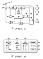
- the MS 100 contains an antenna 102 preferably coupled to a duplex filter or antenna switch 104 that provides isolation between receive and transmit chains within MS 100.
- the receiver chain includes receiver front-end circuitry 106 (effectively providing reception, filtering and intermediate or base-band frequency conversion).
- the front-end circuit 106 is serially coupled to a signal processing function (generally realised by a digital signal processor (DSP)) 108 via a baseband (back-end) processing circuit 107.
- DSP digital signal processor
- a controller 114 is operably coupled to the front-end circuitry 106 and a received signal strength indication (RSSI) function 112; so that the receiver can calculate receive bit-error-rate (BER) or frame-error-rate (FER) or similar link-quality measurement data from recovered information via the RSSI function 112.
- RSSI received signal strength indication
- a memory device 116 is operably coupled to the signal processing function 108 and controller 114 and stores a wide array of MS-specific data, for example decoding/encoding information and voltages to be applied to components in the audio circuit to produce a specific audio performance.
- a timer 118 is operably coupled to the controller 114 to control the timing of operations, namely the transmission or reception of time-dependent signals such as speech frames, within the MS 100.
- received signals that are processed by the signal processing function 108 are typically applied to an output device 110 of a user interface 122, such as a speaker or display.
- the transmit chain comprises an input device 120 of the user interface 122, such as a microphone or keypad, operably coupled to the processor 108.
- An output from the signal processing function 108 is input to the transmitter/modulation circuitry 128 and thereon to a power amplifier 130.
- the signal processing function 108, transmitter/modulation circuitry 128 and the power amplifier 130 are operationally responsive to the controller 114, with an output from the power amplifier coupled to the duplex filter or antenna switch 104, as known in the art.
- a look-up table within the memory device 116 is preferably constructed to store audio quality parameter information of the MS 100.
- the signal processing function 108 has been adapted to comprise microphone/audio sensitivity algorithms and/or features 126, which are configured to implement the inventive concepts herein described.
- a monitoring user's communication unit such as a dispatch console, comprises a memory device operably coupled to a processor and a transceiver, with the memory device storing audio quality information of one or more noise-affected remote subscriber communication units.
- the signal processor 108 is configured to send or receive any of the following PDU message types, preferably in the context of an ambience listening call:
- the audio quality of the subscriber communication unit is remotely controlled by management of a set of audio quality parameters, for example one or more of the following:
- the new CAQ messages preferably include one or more of the above parameters as they are described in Table 1 below: PDU name Dir'n Parameters Values CAQ REQUEST MA Mic Gain Any value in dB AGC On/Off NR Any value in dB Response Immediate/Not Immediate CAQ RESPONSE AM Report Accept/Reject Mic Gain Current mic gain value in dB Range of Mic Gains Min and max mic gains in dB AGC On/Off/Disabled NS Status On/Off/Disabled NR Current NR in dB Max NR Max NR in dB CAQ INTERROGATION MA Response Immediate/Not Immediate CAQ INDICATION AM Mic Gain Current mic gain value in dB Range of Mic Gains Min and max mic gains in dB AGC On/Off/Disabled NS Status On/Off/Disabled NR Current NR in dB Max NR Max NR in dB
- signal processing function 108 and controller 114 arrangement may be combined into one element, operably connected or separate functions interconnected in a reasonable manner as known in the art.
- the various components within the MS 100 can be realised in discrete or integrated component form.
- the MS 100 may be any radio transmitter and/or receiver device, such as a portable or mobile PMR radio, a mobile phone, a personal data assistant (PDA), a wireless-capable laptop computer.
- a portable or mobile PMR radio such as a portable or mobile PMR radio, a mobile phone, a personal data assistant (PDA), a wireless-capable laptop computer.
- PDA personal data assistant
- the user interface 200 comprises a visual display of a microphone gain setting 205, an indication of whether an AGC circuit is switched on/off 210 and a visual display of a noise reduction setting 215.
- user input controls are provided for configuring microphone sensitivity algorithms and/or features 220, applying a default set of parameters 225 or performing a check of the parameters that are currently being used 230.
- the monitoring user is able to interpret the reasons for the poor quality of the ambience listening call and effect appropriate changes to the affected user's communication unit.
- the user interface 200 is operably coupled to a transceiver to transmit and receive appropriate microphone sensitivity commands or information.
- a signal flow diagram 300 illustrates an example of a monitoring user 320 successfully changing audio quality of a remote subscriber user 310 in a call.
- the scenario shows how the monitoring user 320 is able to change audio parameters for an existing ambience listening call.
- the monitoring user 320 After an ambience listening call has been established 330, the monitoring user 320 is provided with the ability to adjust audio quality parameters on the remote subscriber communication unit 310 whilst participating in a call. In order to achieve this control, the monitoring user 320 initiates the sending of a CAQ REQUEST protocol data unit (PDU) 335 to the subscriber communication unit 310.
- the CAQ REQUEST PDU 335 proposes desirable values of the audio parameters, as determined by the monitoring user 320.
- the radio unit has an opportunity to respond to a CAQ REQUEST PDU and/or a CAQ INTERROGATION PDU in a special free-from-traffic frame (say, in TETRA - every 18 th frame in a 1-second long multiframe). If an "immediate" response is requested, the radio unit will "steal" traffic slots in order to send a CAQ response/indication PDU.
- the subscriber communication unit 310 upon reception of the CAQ REQUEST PDU 335, will assess the proposed audio parameters contained within the CAQ REQUEST PDU 335. If the proposed audio parameters are acceptable, the subscriber communication unit 310 will try to re-configure the audio parameters in his/her radio with these new parameters 355. As shown, the values of the received parameters in this case were acceptable and the subscriber communication unit 310 preferably responds to the monitoring user 320 with a CAQ RESPONSE PDU 360 indicating a successful adjustment of the audio parameters on the affected radio. The monitoring user then updates the audio parameter settings 365 that it has recorded for the subscriber communication unit 310.
- a message sequence flowhart illustrates how a monitoring user 320 fails to change audio parameters for the existing ambience listening call when trying to configure an audio quality for the remote subscriber communication unit 310, say, by using incorrect or unacceptable parameters.
- the monitoring user 320 is provided with the ability to adjust audio quality parameters of the remote subscriber communication unit 310.
- the monitoring user 320 initiates the sending of a CAQ REQUEST protocol data unit (PDU) in step 435 to the remote subscriber communication unit 310.
- PDU CAQ REQUEST protocol data unit
- the CAQ REQUEST PDU in step 435 proposes desirable values of the audio parameters, as determined by the monitoring user 320.
- the radio unit has an opportunity to respond to a CAQ REQUEST PDU and/or a CAQ INTERROGATION PDU in a special free-from-traffic frame. If an "immediate" response is requested, the radio unit will preferably "steal" traffic slots in order to send a CAQ response/indication PDU.
- the remote subscriber communication unit 310 upon reception of the CAQ REQUEST PDU, will assess the proposed audio parameters contained within the CAQ REQUEST PDU in step 435. If, in this scenario, some of the parameters were available or acceptable and some were unavailable or unacceptable, the subscriber communication unit 310 will preferably send a CAQ RESPONSE PDU 460 to the monitoring user 320.
- the CAQ RESPONSE PDU 460 preferably indicates a failure of the subscriber communication unit 310 to react to the CAQ REQUEST PDU 435.
- the CAQ RESPONSE PDU 460 also preferably provides details of both the current audio setting (e.g. microphone gain, NS and AGC status) of the noise-affected remote subscriber communication unit 310, as well as, for example, the available ranges of microphone gains and/or level of maximum noise reduction.
- the monitoring user 320 changes the parameters in step 445 and uses the correct parameters in a subsequent (second) CAQ request 470 sent to the remote subscriber communication unit 320, in a second attempt to (re-)configure the audio quality.
- the remote subscriber communication unit 310 sets the audio quality of his/her radio with these new audio quality parameters in step 455.
- the remote subscriber communication unit 310 then preferably responds to the monitoring user 320 with a CAQ RESPONSE PDU 475 indicating a successful adjustment of the audio parameters of the affected radio.
- the monitoring user then updates the audio parameter settings 465 that it has recorded for the remote subscriber communication unit 310.
- an audio quality negotiation process enables the monitoring user 320 to change the audio parameters and/or circuits/components employed by the remote subscriber communication unit 310.
- an audio quality parameter interrogation process is illustrated in the message sequence flowchart of FIG. 5.
- the interrogation process is performed prior to audio (re-) configuration.
- This scenario shows how a monitoring user uses an interrogation message in order to check the audio characteristics of the remote subscriber communication unit prior to (re-)configuring it.
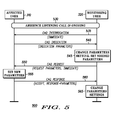
- the monitoring user 320 sends a CAQ INTERROGATION PDU 535 to the remote subscriber communication unit 310 to obtain knowledge about the available audio parameters at the remote subscriber communication unit 310.
- the remote subscriber communication unit 310 has to respond with a CAQ INDICATION PDU 540 indicating the values of specific or all audio parameters.
- the monitoring user 320 modifies the parameters in step 545 and uses the correct parameters in a first CAQ request 550 sent to the remote subscriber communication unit 320, in order to (re-)configure the audio quality.
- the values of the received parameters were acceptable to the remote subscriber communication unit 310.
- the remote subscriber communication unit 310 sets the audio quality of his/her radio with these new audio quality parameters in step 555.
- the remote subscriber communication unit 310 then preferably responds to the monitoring user 320 with a CAQ RESPONSE PDU 560 indicating a successful adjustment of the audio parameters of the affected radio.
- the monitoring user then updates the audio parameter settings 565 that it has recorded for the remote subscriber communication unit 310.
- the aforementioned mechanisms enable a monitoring user to obtain a variety of information about the audio capabilities of a subscriber unit user.
- This information is preferably applied to a software application employed in a processor on the monitoring user side.
- the software application preferably illustrates values for some or all of the audio parameters, for example, microphone gain, NR, AGC status, etc. indicating the current audio quality values and audio quality ranges. This enables the monitoring user to easily interpret and (re-)configure the audio quality of the remote subscriber communication unit 310.
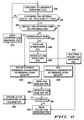
- a flowchart 600 summarises the basic algorithm of how a monitoring user may control audio quality of an ambience listening call by using the aforementioned PDUs, in accordance with the preferred embodiment of the present invention.
- the preferred algorithm commences with a monitoring user performing an ambience listening operation of a noise-affected remote subscriber communication unit, as shown in step 610. Note that the steps performed by the remote subscriber unit are highlighted as '*' in FIG. 6.
- step 615 When the monitoring user determines, in step 615, that the audio quality settings of the remote subscriber communication unit need to be changed, a determination is made as to whether the affected remote subscriber communication unit should be interrogated, as shown in step 620. If it is determined that the affected remote subscriber communication unit should be interrogated, a determination is made as to whether any interrogation should be made immediately or not, in step 625. If an interrogation is to be made immediately (or at least relatively soon), in step 625, a CAQ INTERROGATE PDU is sent by the monitoring user in step 630.
- the monitoring communication unit then receives a CAQ INDICATION PDU, as shown in step 635.
- the CAQ INDICATION PDU comprises an indication of some or all of the audio parameters used by the noise-affected remote subscriber communication unit.
- the monitoring user selects desirable audio quality parameters to be sent to the remote subscriber communication unit, in step 640.
- the monitoring user intuitively sets the desirable audio quality parameters to be used by the remote subscriber communication unit, in step 645.
- the monitoring user sends a CAQ REQUEST PDU to the remote subscriber communication unit with the desirable audio quality parameters, as shown in step 650.
- the remote subscriber communication unit then receives the CAQ REQUEST PDU in step 655 and determines whether to accept the monitoring user's recommended audio quality parameters in step 660. If the remote subscriber communication unit decides not to accept the audio quality recommendations contained within the received CAQ REQUEST PDU in step 660, the remote subscriber communication unit may then send a CAQ RESPONSE PDU, in step 665, to the monitoring user which receives the CAQ response PDU in step 675. The CAQ RESPONSE PDU informs the monitoring user that the audio quality parameters have not been updated according to the monitoring user's recommendations. In this regard, the monitoring user may then select alternative desirable audio quality parameters to be sent to the remote subscriber communication unit, in step 640.
- the remote subscriber communication unit modifies its respective audio parameters, algorithms, circuits and/or component settings accordingly, in step 680.
- the remote subscriber communication unit may then send a CAQ RESPONSE PDU to the monitoring user in step 670, informing the monitoring user that the audio quality parameters have been modified according to the recommendations.
- the process then returns to step 610 with the monitoring user performing an ambience listening operation of a noise-affected remote subscriber communication unit.
- inventive concepts of the present invention can be used in any scenario where remote controlling of remote audio devices is desired.
- One preferred example of such an application is in a TErrestrial Trunked RAdio (TETRA) wireless communication system, where a dispatcher is performing ambience listening or wishes to control the audio attributes of a monitored remote subscriber radio unit.
- TETRA TErrestrial Trunked RAdio
Abstract
Description
- This invention relates to ambience listening in a wireless communication system which includes at at least one subscriber communication unit and a monitoring communication unit.
- In the field of this invention, it is known that the ambience listening feature is one of the voice supplementary services supported in radio communication systems such as the TETRA (Terrestrial Trunked Radio) communication system, as defined in the industry standards of the European Telecommunications Standards Institute (ETSI). Ambience listening allows an authorized user to establish a call with a specific subscriber communication unit for the purpose of monitoring voice activity in the vicinity of that subscriber, without obviously initiating any indication to the user of the subscriber communication unit that he/she is being remotely monitored.
- Thus, ambience listening is often considered to be a means of increasing the subscriber unit user's safety.
In situations where the dispatcher has received an alarm, or has a suspicion that the user is, say, in a life-threatening situation, the dispatcher can invoke Ambience listening to help determine what is happening to the user. Ambience listening is normally activated or ceased by the dispatcher sending an ambience listening command to the subscriber communication unit in question. - The ability of a monitoring communication unit to successfully perform such remote (ambience) listening is known to be affected by the following parameters:
- (i) Microphone sensitivity of the subscriber communication unit. This is dependent upon the operation of any equalizer, which, in turn, is dependent upon the background conditions at the user, e.g. noise, conversations, etc.
- (ii) Any activated algorithms within the subscriber communication unit, such as transmit automatic gain control (AGC), noise-suppression, double-talk detection, voice alternators, etc.
- (iii) Different operational modes within the subscriber communication unit, such as discontinuous transmission (DTX) being employed as part of a current saving initiative.
-
- In particular, microphone sensitivity is known to be a critical determining factor in an ambience listening process. When the microphone sensitivity is too high, a normal speech level may cause the microphone/audio circuit to saturate, thereby causing voice distortion.
In addition, high microphone sensitivity increases the level of the environmental noise entering the microphone/audio circuit. Thus, these two factors reduce the intelligibility of the remotely monitored communication. In contrast, when the microphone sensitivity is too low, the microphone circuit may not be capable of providing sufficient gain to the voice signal that is input to the microphone. Hence, the monitoring user will find it difficult to understand communication at the remote subscriber. - In accordance with a first aspect of the present invention, there is provided a communication system. The communication system comprises a subscriber communication unit participating in a call. A monitoring communication unit performs an ambience listening operation of the subscriber communication unit when participating in the call. The monitoring communication unit is configured to request modification of one or more audio quality parameters of the subscriber communication unit whilst performing the ambience listening operation.
- The subscriber communication unit is preferably configured to modify one or more of its audio quality parameters in response to the request by the monitoring communication unit.
- In this manner, a monitoring user/communication unit is able to adjust audio attributes of a noise affected user to improve speech intelligibility during an ambience listening call.
- In accordance with a second aspect of the present invention, there is provided a method of remotely controlling audio parameters of a subscriber communication unit. The method comprises a monitoring communication unit performing an ambience listening operation of a noise affected communication unit. The method further comprises the monitoring communication unit determining whether one or more audio quality settings of the noise affected communication unit is/are to be modified. The monitoring communication unit sends a message to the affected communication unit requesting a call audio quality or parameter change. The message is received by the affected communication unit; which sets its audio quality parameters in response to the message.
- In accordance with a third aspect of the present invention, there is provided a monitoring communication unit. The monitoring communication unit comprises a transceiver and a processor, operably coupled to the transceiver, to perform ambience listening of a subscriber communication unit participating in a call. The monitoring communication unit further comprises a monitoring function, operably coupled to the processor, for monitoring a call audio quality of the subscriber communication unit participating in a call, such that the processor requests a modification of one or more call audio quality parameter(s) of the subscriber communication unit in response to the call audio quality monitoring.
- In accordance with a fourth aspect of the present invention, there is provided a subscriber communication unit. The subscriber communication unit comprises a transceiver and a processor, operably coupled to the transceiver, controlling one or more audio quality parameters of the subscriber communication unit. The processor is configured to modify one or more call audio quality parameters of the subscriber communication unit in response to receiving a request to modify such parameter(s) from a monitoring communication unit performing ambience listening of a call of the subscriber communication unit.
- Preferably, the audio quality parameters that are modified comprise microphone sensitivity circuits/elements and/or activating one or more audio algorithms in the subscriber communication unit.
- Further, the monitoring communication unit is preferably configured to interrogate the subscriber communication unit, in order to determine one or more values of call audio quality parameters that is/are employed by the subscriber communication unit. In this manner, the monitoring communication unit is able to determine audio quality parameters associated with the affected communication unit, when it determines that an ambience listening call is suffering from poor audio quality, and thereafter recommend appropriate changes.
- In addition, the preferred embodiment of the present invention provides a variety of protocol data messages to facilitate ambience listening of a call of a remote subscriber communication unit.
- Further features of the present invention are as claimed in the dependent Claims.
- The present invention beneficially provides a method, and products operating the method, by which audio quality factors affecting ambience listening of a subscriber communication unit, e.g. a portable or mobile radio, a mobile telephone, a personal data assistant, or a wireless capable laptop or portable computer, may be remotely controlled or adjusted by a monitoring communication unit, e.g. a fixed or mobile terminal operated by a system controller, operating by wireless communication between the two units.
- Exemplary embodiments of the present invention will now be described, with reference to the accompanying drawings, in which:
- FIG. 1 illustrates a block diagram representation of a wireless communication unit adapted to modify one or more call audio quality parameters in accordance with a preferred embodiment of the present invention;
- FIG. 2 illustrates a user interface for a monitoring user according to a preferred embodiment of the present invention;
- FIG. 3 illustrates a message sequence flowchart of an example of a monitoring user successfully changing audio parameters of a subscriber user on-line, in accordance with a preferred embodiment of the present invention;
- FIG. 4 illustrates a message sequence flowchart of how a monitoring user fails to change audio parameters for an existing Ambience Listening call, in accordance with a preferred embodiment of the present invention;
- FIG. 5 illustrates a message sequence flowchart of an audio quality parameter interrogation process in accordance with a preferred embodiment of the present invention; and
- FIG. 6 illustrates a flowchart of an algorithm of how a monitoring user may control audio quality of an ambience listening call, in accordance with a preferred embodiment of the present invention.
-
- In considering how best to implement an ambience listening mechanism in, say, a TETRA communication system, the inventors of the present invention have appreciated the problems associated with employing a pre-defined audio quality setting of a parameter or circuit component, such as a microphone sensitivity setting. A pre-defined microphone sensitivity setting is likely to be ineffective in practice, due to an unknown and variable distance between the subscriber communication unit and the receiving/monitoring communication unit (i.e. communication from a subscriber user at the extremity of the receiving communication unit's receiver sensitivity will exhibit poor quality audio). Furthermore, employing a pre-defined microphone sensitivity setting is likely to be ineffective due to the indeterminate and variable affect on the communication from other voices and/or noise in the subscriber unit's vicinity.
- The preferred embodiment of the present invention therefore proposes a mechanism to remotely control one or more audio quality parameters, such as microphone sensitivity, in a wireless communication unit. The inventive concepts are described below in the context of a remote microphone sensitivity algorithm, which sets microphone sensitivity based upon the background conditions around the affected and monitored user. For example, if the user is at a noisy location, a noise-suppressor algorithm may be activated and arranged to utilise as much of the noise suppression range as possible.
- In particular, to overcome the difficulty of setting the microphone senstivity, as well as activating relevant algorithms and/or features, it is proposed to allow a monitoring user to modify the microphone gain and/or enable/disable such microphone senstivity algorithms, circuits and/or features at the subscriber communication unit according to the dynamic background conditions in the vicinity of the subscriber communication unit at that time. In such a manner, a monitoring user will be able to adjust the microphone sensitivity of a remote subscriber communication unit during an ambience listening call.
- Referring now to FIG. 1, a block diagram of a wireless subscriber unit/mobile station (MS) 100, adapted to support the inventive concepts of the preferred embodiments of the present invention, is shown. The MS 100 contains an
antenna 102 preferably coupled to a duplex filter orantenna switch 104 that provides isolation between receive and transmit chains withinMS 100. The receiver chain includes receiver front-end circuitry 106 (effectively providing reception, filtering and intermediate or base-band frequency conversion). The front-end circuit 106 is serially coupled to a signal processing function (generally realised by a digital signal processor (DSP)) 108 via a baseband (back-end)processing circuit 107. Acontroller 114 is operably coupled to the front-end circuitry 106 and a received signal strength indication (RSSI)function 112; so that the receiver can calculate receive bit-error-rate (BER) or frame-error-rate (FER) or similar link-quality measurement data from recovered information via theRSSI function 112. - A
memory device 116 is operably coupled to thesignal processing function 108 andcontroller 114 and stores a wide array of MS-specific data, for example decoding/encoding information and voltages to be applied to components in the audio circuit to produce a specific audio performance. Atimer 118 is operably coupled to thecontroller 114 to control the timing of operations, namely the transmission or reception of time-dependent signals such as speech frames, within theMS 100. As known in the art, received signals that are processed by thesignal processing function 108 are typically applied to anoutput device 110 of auser interface 122, such as a speaker or display. - The transmit chain comprises an
input device 120 of theuser interface 122, such as a microphone or keypad, operably coupled to theprocessor 108. An output from thesignal processing function 108 is input to the transmitter/modulation circuitry 128 and thereon to apower amplifier 130. Thesignal processing function 108, transmitter/modulation circuitry 128 and thepower amplifier 130 are operationally responsive to thecontroller 114, with an output from the power amplifier coupled to the duplex filter orantenna switch 104, as known in the art. - In accordance with the preferred embodiment of the present invention, a look-up table within the
memory device 116 is preferably constructed to store audio quality parameter information of theMS 100. In addition, thesignal processing function 108 has been adapted to comprise microphone/audio sensitivity algorithms and/or features 126, which are configured to implement the inventive concepts herein described. In a similar manner, a monitoring user's communication unit, such as a dispatch console, comprises a memory device operably coupled to a processor and a transceiver, with the memory device storing audio quality information of one or more noise-affected remote subscriber communication units. - In this regard, it is proposed that new ambience listening messages, in the form of protocol data units (PDUs), are incorporated into the TETRA standard for the purpose of controlling the ambience listening call audio quality (CAQ). Thus, the
signal processor 108 is configured to send or receive any of the following PDU message types, preferably in the context of an ambience listening call: - (i) CAQ REQUEST PDU: issued by the monitoring user to the subscriber communication unit for (re-) configuring an audio performance of the ambience listening call. It is proposed that the monitoring user will also preferably be able to demand an immediate response to any CAQ PDU request;
- (ii) CAQ RESPONSE PDU: issued by the subscriber communication unit to the monitoring user as a response to the CAQ REQUEST PDU; this response will indicate whether the (re-)configuration of the remote subscriber unit was successful or failed;
- (iii) CAQ INTERROGATION PDU issued by the monitoring user to the subscriber communication unit to enquire about the current ability of the subscriber communication unit to control/modify audio parameters to affect its audio quality; and
- (iv) CAQ INDICATION PDU issued by the subscriber communication unit to the monitoring user as a response to the CAQ interrogation PDU.
-
- The audio quality of the subscriber communication unit is remotely controlled by management of a set of audio quality parameters, for example one or more of the following:
- (i) Microphone gain (current or requested);
- (ii) Selection of a range of a microphone gain (if a number of ranges are available);
- (iii) The AGC status, i.e. On/Off/Disabled;
- (iv) Noise suppression (NS) status, i.e. On/Off/Disabled;
- (v) Noise reduction (NR) level; and
- (vi) A maximum level for noise reduction.
-
- The new CAQ messages preferably include one or more of the above parameters as they are described in Table 1 below:
PDU name Dir'n Parameters Values CAQ REQUEST MA Mic Gain Any value in dB AGC On/Off NR Any value in dB Response Immediate/Not Immediate CAQ RESPONSE AM Report Accept/Reject Mic Gain Current mic gain value in dB Range of Mic Gains Min and max mic gains in dB AGC On/Off/Disabled NS Status On/Off/Disabled NR Current NR in dB Max NR Max NR in dB CAQ INTERROGATION MA Response Immediate/Not Immediate CAQ INDICATION AM Mic Gain Current mic gain value in dB Range of Mic Gains Min and max mic gains in dB AGC On/Off/Disabled NS Status On/Off/Disabled NR Current NR in dB Max NR Max NR in dB - It is within the contemplation of the present invention that the
signal processing function 108 andcontroller 114 arrangement may be combined into one element, operably connected or separate functions interconnected in a reasonable manner as known in the art. - Of course, the various components within the
MS 100 can be realised in discrete or integrated component form. Furthermore, it is within the contemplation of the invention that theMS 100 may be any radio transmitter and/or receiver device, such as a portable or mobile PMR radio, a mobile phone, a personal data assistant (PDA), a wireless-capable laptop computer. - Referring now to FIG. 2, a user interface 200 for a monitoring user is illustrated according to a preferred embodiment of the present invention. The user interface 200 comprises a visual display of a microphone gain setting 205, an indication of whether an AGC circuit is switched on/off 210 and a visual display of a noise reduction setting 215. In addition, user input controls are provided for configuring microphone sensitivity algorithms and/or features 220, applying a default set of
parameters 225 or performing a check of the parameters that are currently being used 230. - Thus, by provision of such audio quality information to a monitoring user, the monitoring user is able to interpret the reasons for the poor quality of the ambience listening call and effect appropriate changes to the affected user's communication unit. In this regard, it is envisaged that the user interface 200 is operably coupled to a transceiver to transmit and receive appropriate microphone sensitivity commands or information.
- Referring now to FIG. 3, a signal flow diagram 300 illustrates an example of a
monitoring user 320 successfully changing audio quality of aremote subscriber user 310 in a call. The scenario shows how themonitoring user 320 is able to change audio parameters for an existing ambience listening call. - After an ambience listening call has been established 330, the
monitoring user 320 is provided with the ability to adjust audio quality parameters on the remotesubscriber communication unit 310 whilst participating in a call. In order to achieve this control, themonitoring user 320 initiates the sending of a CAQ REQUEST protocol data unit (PDU) 335 to thesubscriber communication unit 310. TheCAQ REQUEST PDU 335 proposes desirable values of the audio parameters, as determined by themonitoring user 320. As the audio control method is used during a voice call, the radio unit has an opportunity to respond to a CAQ REQUEST PDU and/or a CAQ INTERROGATION PDU in a special free-from-traffic frame (say, in TETRA - every 18th frame in a 1-second long multiframe). If an "immediate" response is requested, the radio unit will "steal" traffic slots in order to send a CAQ response/indication PDU. - In turn, the
subscriber communication unit 310, upon reception of theCAQ REQUEST PDU 335, will assess the proposed audio parameters contained within theCAQ REQUEST PDU 335. If the proposed audio parameters are acceptable, thesubscriber communication unit 310 will try to re-configure the audio parameters in his/her radio with thesenew parameters 355. As shown, the values of the received parameters in this case were acceptable and thesubscriber communication unit 310 preferably responds to themonitoring user 320 with aCAQ RESPONSE PDU 360 indicating a successful adjustment of the audio parameters on the affected radio. The monitoring user then updates theaudio parameter settings 365 that it has recorded for thesubscriber communication unit 310. - In an enhanced embodiment of the present invention, and referring now to FIG. 4, a message sequence flowhart illustrates how a
monitoring user 320 fails to change audio parameters for the existing ambience listening call when trying to configure an audio quality for the remotesubscriber communication unit 310, say, by using incorrect or unacceptable parameters. Again, in this scenario, after an ambience listening call has been established 430, themonitoring user 320 is provided with the ability to adjust audio quality parameters of the remotesubscriber communication unit 310. In order to achieve this control, themonitoring user 320 initiates the sending of a CAQ REQUEST protocol data unit (PDU) instep 435 to the remotesubscriber communication unit 310. - The CAQ REQUEST PDU in
step 435 proposes desirable values of the audio parameters, as determined by themonitoring user 320. Again, as the audio control method is used during a voice call, the radio unit has an opportunity to respond to a CAQ REQUEST PDU and/or a CAQ INTERROGATION PDU in a special free-from-traffic frame. If an "immediate" response is requested, the radio unit will preferably "steal" traffic slots in order to send a CAQ response/indication PDU. - In turn, the remote
subscriber communication unit 310, upon reception of the CAQ REQUEST PDU, will assess the proposed audio parameters contained within the CAQ REQUEST PDU instep 435. If, in this scenario, some of the parameters were available or acceptable and some were unavailable or unacceptable, thesubscriber communication unit 310 will preferably send aCAQ RESPONSE PDU 460 to themonitoring user 320. TheCAQ RESPONSE PDU 460 preferably indicates a failure of thesubscriber communication unit 310 to react to theCAQ REQUEST PDU 435. TheCAQ RESPONSE PDU 460 also preferably provides details of both the current audio setting (e.g. microphone gain, NS and AGC status) of the noise-affected remotesubscriber communication unit 310, as well as, for example, the available ranges of microphone gains and/or level of maximum noise reduction. - In response, the
monitoring user 320 changes the parameters in step 445 and uses the correct parameters in a subsequent (second)CAQ request 470 sent to the remotesubscriber communication unit 320, in a second attempt to (re-)configure the audio quality. This time, the values of the received parameters were acceptable to thesubscriber communication unit 310. The remotesubscriber communication unit 310 sets the audio quality of his/her radio with these new audio quality parameters instep 455. The remotesubscriber communication unit 310 then preferably responds to themonitoring user 320 with aCAQ RESPONSE PDU 475 indicating a successful adjustment of the audio parameters of the affected radio. The monitoring user then updates theaudio parameter settings 465 that it has recorded for the remotesubscriber communication unit 310. In this regard, an audio quality negotiation process enables themonitoring user 320 to change the audio parameters and/or circuits/components employed by the remotesubscriber communication unit 310. - In a yet further enhancement to the preferred embodiment of the present invention, an audio quality parameter interrogation process is illustrated in the message sequence flowchart of FIG. 5. The interrogation process is performed prior to audio (re-) configuration. This scenario shows how a monitoring user uses an interrogation message in order to check the audio characteristics of the remote subscriber communication unit prior to (re-)configuring it.
- Again in this scenario after an ambience listening call has been established 530, the
monitoring user 320 sends aCAQ INTERROGATION PDU 535 to the remotesubscriber communication unit 310 to obtain knowledge about the available audio parameters at the remotesubscriber communication unit 310. In response to theCAQ INTERROGATION PDU 535, the remotesubscriber communication unit 310 has to respond with aCAQ INDICATION PDU 540 indicating the values of specific or all audio parameters. - In response, the
monitoring user 320 modifies the parameters instep 545 and uses the correct parameters in afirst CAQ request 550 sent to the remotesubscriber communication unit 320, in order to (re-)configure the audio quality. In this case, the values of the received parameters were acceptable to the remotesubscriber communication unit 310. The remotesubscriber communication unit 310 sets the audio quality of his/her radio with these new audio quality parameters instep 555. The remotesubscriber communication unit 310 then preferably responds to themonitoring user 320 with aCAQ RESPONSE PDU 560 indicating a successful adjustment of the audio parameters of the affected radio. The monitoring user then updates theaudio parameter settings 565 that it has recorded for the remotesubscriber communication unit 310. - Thus, the aforementioned mechanisms enable a monitoring user to obtain a variety of information about the audio capabilities of a subscriber unit user. This information is preferably applied to a software application employed in a processor on the monitoring user side. The software application preferably illustrates values for some or all of the audio parameters, for example, microphone gain, NR, AGC status, etc. indicating the current audio quality values and audio quality ranges. This enables the monitoring user to easily interpret and (re-)configure the audio quality of the remote
subscriber communication unit 310. - Referring now to FIG. 6, a flowchart 600 summarises the basic algorithm of how a monitoring user may control audio quality of an ambience listening call by using the aforementioned PDUs, in accordance with the preferred embodiment of the present invention. The preferred algorithm commences with a monitoring user performing an ambience listening operation of a noise-affected remote subscriber communication unit, as shown in
step 610.
Note that the steps performed by the remote subscriber unit are highlighted as '*' in FIG. 6. - A determination is made by the monitoring user, in
step 615, as to whether the audio quality settings of the remote subscriber communication unit are acceptable or need to be changed, for example whether the audio quality is good, how intelligible is the recovered voice, etc. - When the monitoring user determines, in
step 615, that the audio quality settings of the remote subscriber communication unit need to be changed, a determination is made as to whether the affected remote subscriber communication unit should be interrogated, as shown instep 620. If it is determined that the affected remote subscriber communication unit should be interrogated, a determination is made as to whether any interrogation should be made immediately or not, instep 625. If an interrogation is to be made immediately (or at least relatively soon), instep 625, a CAQ INTERROGATE PDU is sent by the monitoring user instep 630. - The monitoring communication unit then receives a CAQ INDICATION PDU, as shown in
step 635. The CAQ INDICATION PDU comprises an indication of some or all of the audio parameters used by the noise-affected remote subscriber communication unit. The monitoring user then selects desirable audio quality parameters to be sent to the remote subscriber communication unit, instep 640. - If an interrogation is not to be made immediately, in
step 625, the monitoring user intuitively sets the desirable audio quality parameters to be used by the remote subscriber communication unit, instep 645. Following the monitoring user determining the desirable audio quality parameters to be used, either intuitively or following an interrogation process, the monitoring user sends a CAQ REQUEST PDU to the remote subscriber communication unit with the desirable audio quality parameters, as shown instep 650. - The remote subscriber communication unit then receives the CAQ REQUEST PDU in
step 655 and determines whether to accept the monitoring user's recommended audio quality parameters instep 660. If the remote subscriber communication unit decides not to accept the audio quality recommendations contained within the received CAQ REQUEST PDU instep 660, the remote subscriber communication unit may then send a CAQ RESPONSE PDU, instep 665, to the monitoring user which receives the CAQ response PDU instep 675. The CAQ RESPONSE PDU informs the monitoring user that the audio quality parameters have not been updated according to the monitoring user's recommendations. In this regard, the monitoring user may then select alternative desirable audio quality parameters to be sent to the remote subscriber communication unit, instep 640. - However, if the remote subscriber communication unit accepts the audio quality recommendations from the received CAQ REQUEST PDU in
step 660, the remote subscriber communication unit modifies its respective audio parameters, algorithms, circuits and/or component settings accordingly, instep 680. - The remote subscriber communication unit may then send a CAQ RESPONSE PDU to the monitoring user in
step 670, informing the monitoring user that the audio quality parameters have been modified according to the recommendations. The process then returns to step 610 with the monitoring user performing an ambience listening operation of a noise-affected remote subscriber communication unit. - It is within the contemplation of the invention that the inventive concepts of the present invention can be used in any scenario where remote controlling of remote audio devices is desired. One preferred example of such an application is in a TErrestrial Trunked RAdio (TETRA) wireless communication system, where a dispatcher is performing ambience listening or wishes to control the audio attributes of a monitored remote subscriber radio unit.
- It will be understood that the communication units and methods of remotely controlling audio parameters of a remote subscriber communication unit, as described above, tend to provide at least one or more of the following advantages:
- (i) A monitoring user/communication unit can adjust audio attributes of a remote subscriber communication unit, for example, to improve speech intelligibility during an ambience listening call; and
- (ii) The inventive concepts are easy to implement on a real-time processor.
-
- Whilst specific, and preferred, implementations of the present invention are described above, it is clear that one skilled in the art could readily apply variations and modifications of such inventive concepts.
- Thus, a mechanism for remote controlling audio parameters in a wireless communication unit is described, which alleviates at least some of the abovementioned disadvantages with known mechanisms.
Claims (21)
- A communication system (300) comprising:wherein the communication system is characterised in that the monitoring communication unit is configured to request modification of one or more audio quality parameters of the subscriber communication unit whilst performing the ambience listening operation.a subscriber communication unit (310) operable to participate in a call; anda monitoring communication unit (320) performing an ambience listening operation of the subscriber communication unit when participating in a call;
- A communication system according to Claim 1 wherein the subscriber communication unit is configured to modify one or more of its audio quality parameters in response to the request by the monitoring communication unit.
- A communication system according to Claim 1 or Claim 2 wherein the audio quality parameters comprise setting a microphone sensitivity level and/or activating one or more audio algorithms in the subscriber communication unit.
- A communication system according to any one preceding Claim wherein the request from the monitoring communication unit comprises an indication of desirable audio quality parameters for the subscriber communication unit to use.
- A communication system according to any one preceding Claim wherein the monitoring communication unit is configured to interrogate the subscriber communication unit to determine one or more call audio quality parameters employed by the subscriber communication unit.
- A communication system according to any one preceding Claim wherein the subscriber communication unit is a mobile radio communication unit, the monitoring communication unit is a dispatch station and the communication system supports a TETRA standard air-interface.
- A method of remotely controlling one or more audio parameters of a subscriber communication unit (310), the method comprising the step of:performing, by a monitoring communication unit (320), an ambience listening operation of the subscriber communication unit;determining, by the monitoring communication unit, whether one or more audio quality settings of the subscriber communication unit is/are to be modified;sending, by the monitoring communication unit to the affected communication unit, a message requesting an audio quality parameter modification,receiving the message by the subscriber communication unit; andsetting audio quality parameters by the subscriber communication unit, in response to the message.
- A method of remotely controlling one or more audio parameters of a subscriber communication unit according to Claim 7 wherein the step of setting audio quality parameters comprises setting a microphone sensitivity level and/or activating one or more audio algorithms in the subscriber communication unit.
- A method of remotely controlling one or more audio parameters of a subscriber communication unit according to Claim 8 wherein the message requesting a call audio quality change comprises an indication of desirable audio quality parameters.
- A method of remotely controlling one or more audio parameters of a subscriber communication unit according to Claim 9 further including the step of:determining, by the subscriber communication unit, whether to accept the monitoring communication unit's indicated audio quality parameters.
- A method of remotely controlling one or more audio parameters of a subscriber communication unit according to any one of preceding Claims 7 to 10 and further including the step of:sending a response message by the subscriber communication unit to the monitoring communication unit to inform the monitoring communication unit that the audio quality parameters have or have not been modified.
- A method of remotely controlling one or more audio parameters of a subscriber communication unit according to any one of preceding Claims 7 to 11 further including the step of:determining, by the monitoring communication unit, whether the subscriber communication unit should be interrogated;sending, an interrogation message by the monitoring communication unit to the subscriber communication unit in response to the determination;sending a call audio quality indication message, by the subscriber communication unit to the monitoring communication unit, in response to the interrogation message.
- A method according to Claim 12 wherein the call audio quality indication message comprises an indication of audio quality parameters employed at the subscriber communication unit.
- A monitoring communication unit (320) operable to perform an ambience listening operation of a subscriber communication unit (310) when the subscriber communication unit is participating in a call; characterised in that the monitoring communication unit is configured to send whilst performing the ambience listening operation a signal requesting modification of one or more audio quality parameters of the subscriber communication unit.
- A monitoring communication unit according to claim 14 comprising:wherein the monitoring communication unit includes:a transceiver; anda processor, operably coupled to the transceiver, operable to perform ambience listening of a subscriber communication unit participating in a call;a monitoring function, operably coupled to the processor, for monitoring a call audio quality of the subscriber communication unit participating in the call such that the processor is operable to request a modification of one or more call audio quality parameters of the subscriber communication unit in response to the call audio quality monitoring.
- A subscriber communication unit (310) operable when participitaing in a call to be monitored by a monitoring communication unit (320) performing an ambience listening operation of the subscriber communication unit when the subscriber communication unit is participating in the call; characterised in that the subscriber communication unit is configured to receive and respond to a signal requesting modification of one or more audio quality parameters of the subscriber communication unit.
- A subscriber communication unit according to claim 16 comprising:wherein the processor is configured to modify one or more call audio quality parameters of the subscriber communication unit in response to receiving a request for such modification from a monitoring communication unit performing ambience listening of a call of the subscriber communication unit.a transceiver; anda processor, operably coupled to the transceiver, controlling one or more audio quality parameters of the subscriber communication unit;
- A subscriber communication unit according to Claim 17, wherein the subscriber communication unit is one of a portable or mobile radio, a mobile telephone, a personal data assistant, and a wireless capable laptop or portable computer.
- A subscriber communication unit according to any one of claims 16 to 18 which is operable to transmit a wireless message to a monitoring communication unit in an ambience listening call in a wireless communcation system, wherein the wireless message comprises an indication of whether the subscriber communication unit has configured or re-configured an audio performance of the ambience listening call.
- A subscriber communication unit according to any one of claims 16 to 19 which is operable to transmit a wireless message to a monitoring communication unit in an ambience listening call in a wireless communcation system, wherein the wireless message comprises information on audio parameters of the subscriber communication unit that affect audio quality of the ambience listening call.
- A monitoring communication unit according to claim 14 or claim 15 which is operable to send a wireless to a remotely monitored subscriber communication unit in an ambience listening call in a wireless communcation system, wherein the wireless message comprises an enquiry of a current ability of the remotely monitored subscriber communication unit to control/modify audio parameters to affect its audio quality.
Applications Claiming Priority (2)
| Application Number | Priority Date | Filing Date | Title |
|---|---|---|---|
| GB0327507A GB2408655B (en) | 2003-11-27 | 2003-11-27 | Communication system, communication units and method of ambience listening thereto |
| GB0327507 | 2003-11-27 |
Publications (3)
| Publication Number | Publication Date |
|---|---|
| EP1536660A2 true EP1536660A2 (en) | 2005-06-01 |
| EP1536660A3 EP1536660A3 (en) | 2008-04-02 |
| EP1536660B1 EP1536660B1 (en) | 2013-10-23 |
Family
ID=29797860
Family Applications (1)
| Application Number | Title | Priority Date | Filing Date |
|---|---|---|---|
| EP04104184.9A Active EP1536660B1 (en) | 2003-11-27 | 2004-09-01 | Communication system, communication units, and method of ambience listening thereto |
Country Status (2)
| Country | Link |
|---|---|
| EP (1) | EP1536660B1 (en) |
| GB (1) | GB2408655B (en) |
Cited By (48)
| Publication number | Priority date | Publication date | Assignee | Title |
|---|---|---|---|---|
| EP1779534A1 (en) * | 2004-07-01 | 2007-05-02 | Motorola, Inc. | A method and a system for operating an ambiance listening mode in a wireless communication system |
| WO2010006211A1 (en) * | 2008-07-11 | 2010-01-14 | In Touch Technologies, Inc. | Tele-presence robot system with multi-cast features |
| US8077963B2 (en) | 2004-07-13 | 2011-12-13 | Yulun Wang | Mobile robot with a head-based movement mapping scheme |
| US8340819B2 (en) | 2008-09-18 | 2012-12-25 | Intouch Technologies, Inc. | Mobile videoconferencing robot system with network adaptive driving |
| US8384755B2 (en) | 2009-08-26 | 2013-02-26 | Intouch Technologies, Inc. | Portable remote presence robot |
| US8463435B2 (en) | 2008-11-25 | 2013-06-11 | Intouch Technologies, Inc. | Server connectivity control for tele-presence robot |
| US8515577B2 (en) | 2002-07-25 | 2013-08-20 | Yulun Wang | Medical tele-robotic system with a master remote station with an arbitrator |
| US8670017B2 (en) | 2010-03-04 | 2014-03-11 | Intouch Technologies, Inc. | Remote presence system including a cart that supports a robot face and an overhead camera |
| US8718837B2 (en) | 2011-01-28 | 2014-05-06 | Intouch Technologies | Interfacing with a mobile telepresence robot |
| US8849679B2 (en) | 2006-06-15 | 2014-09-30 | Intouch Technologies, Inc. | Remote controlled robot system that provides medical images |
| US8849680B2 (en) | 2009-01-29 | 2014-09-30 | Intouch Technologies, Inc. | Documentation through a remote presence robot |
| US8892260B2 (en) | 2007-03-20 | 2014-11-18 | Irobot Corporation | Mobile robot for telecommunication |
| US8930019B2 (en) | 2010-12-30 | 2015-01-06 | Irobot Corporation | Mobile human interface robot |
| US8935005B2 (en) | 2010-05-20 | 2015-01-13 | Irobot Corporation | Operating a mobile robot |
| US8996165B2 (en) | 2008-10-21 | 2015-03-31 | Intouch Technologies, Inc. | Telepresence robot with a camera boom |
| US9014848B2 (en) | 2010-05-20 | 2015-04-21 | Irobot Corporation | Mobile robot system |
| US9174342B2 (en) | 2012-05-22 | 2015-11-03 | Intouch Technologies, Inc. | Social behavior rules for a medical telepresence robot |
| US9193065B2 (en) | 2008-07-10 | 2015-11-24 | Intouch Technologies, Inc. | Docking system for a tele-presence robot |
| US9251313B2 (en) | 2012-04-11 | 2016-02-02 | Intouch Technologies, Inc. | Systems and methods for visualizing and managing telepresence devices in healthcare networks |
| US9264664B2 (en) | 2010-12-03 | 2016-02-16 | Intouch Technologies, Inc. | Systems and methods for dynamic bandwidth allocation |
| US9323250B2 (en) | 2011-01-28 | 2016-04-26 | Intouch Technologies, Inc. | Time-dependent navigation of telepresence robots |
| US9361021B2 (en) | 2012-05-22 | 2016-06-07 | Irobot Corporation | Graphical user interfaces including touchpad driving interfaces for telemedicine devices |
| US9375843B2 (en) | 2003-12-09 | 2016-06-28 | Intouch Technologies, Inc. | Protocol for a remotely controlled videoconferencing robot |
| US9498886B2 (en) | 2010-05-20 | 2016-11-22 | Irobot Corporation | Mobile human interface robot |
| US9610685B2 (en) | 2004-02-26 | 2017-04-04 | Intouch Technologies, Inc. | Graphical interface for a remote presence system |
| US9668048B2 (en) | 2015-01-30 | 2017-05-30 | Knowles Electronics, Llc | Contextual switching of microphones |
| US9699554B1 (en) | 2010-04-21 | 2017-07-04 | Knowles Electronics, Llc | Adaptive signal equalization |
| US9715337B2 (en) | 2011-11-08 | 2017-07-25 | Intouch Technologies, Inc. | Tele-presence system with a user interface that displays different communication links |
| US9838784B2 (en) | 2009-12-02 | 2017-12-05 | Knowles Electronics, Llc | Directional audio capture |
| US9917945B2 (en) | 2014-06-16 | 2018-03-13 | Dolby Laboratories Licensing Corporation | In-service monitoring of voice quality in teleconferencing |
| US9978388B2 (en) | 2014-09-12 | 2018-05-22 | Knowles Electronics, Llc | Systems and methods for restoration of speech components |
| US9974612B2 (en) | 2011-05-19 | 2018-05-22 | Intouch Technologies, Inc. | Enhanced diagnostics for a telepresence robot |
| US10259119B2 (en) | 2005-09-30 | 2019-04-16 | Intouch Technologies, Inc. | Multi-camera mobile teleconferencing platform |
| US10321490B2 (en) | 2016-11-30 | 2019-06-11 | Motorola Solutions, Inc. | Systems and methods for maintaining an ambient monitoring session |
| US10334205B2 (en) | 2012-11-26 | 2019-06-25 | Intouch Technologies, Inc. | Enhanced video interaction for a user interface of a telepresence network |
| US10343283B2 (en) | 2010-05-24 | 2019-07-09 | Intouch Technologies, Inc. | Telepresence robot system that can be accessed by a cellular phone |
| US10471588B2 (en) | 2008-04-14 | 2019-11-12 | Intouch Technologies, Inc. | Robotic based health care system |
| US10682763B2 (en) | 2007-05-09 | 2020-06-16 | Intouch Technologies, Inc. | Robot system that operates through a network firewall |
| US10762170B2 (en) | 2012-04-11 | 2020-09-01 | Intouch Technologies, Inc. | Systems and methods for visualizing patient and telepresence device statistics in a healthcare network |
| US10769739B2 (en) | 2011-04-25 | 2020-09-08 | Intouch Technologies, Inc. | Systems and methods for management of information among medical providers and facilities |
| US10808882B2 (en) | 2010-05-26 | 2020-10-20 | Intouch Technologies, Inc. | Tele-robotic system with a robot face placed on a chair |
| US10875182B2 (en) | 2008-03-20 | 2020-12-29 | Teladoc Health, Inc. | Remote presence system mounted to operating room hardware |
| US10969766B2 (en) | 2009-04-17 | 2021-04-06 | Teladoc Health, Inc. | Tele-presence robot system with software modularity, projector and laser pointer |
| US11154981B2 (en) | 2010-02-04 | 2021-10-26 | Teladoc Health, Inc. | Robot user interface for telepresence robot system |
| US11389064B2 (en) | 2018-04-27 | 2022-07-19 | Teladoc Health, Inc. | Telehealth cart that supports a removable tablet with seamless audio/video switching |
| US11636944B2 (en) | 2017-08-25 | 2023-04-25 | Teladoc Health, Inc. | Connectivity infrastructure for a telehealth platform |
| US11742094B2 (en) | 2017-07-25 | 2023-08-29 | Teladoc Health, Inc. | Modular telehealth cart with thermal imaging and touch screen user interface |
| US11862302B2 (en) | 2017-04-24 | 2024-01-02 | Teladoc Health, Inc. | Automated transcription and documentation of tele-health encounters |
Families Citing this family (3)
| Publication number | Priority date | Publication date | Assignee | Title |
|---|---|---|---|---|
| US11399153B2 (en) | 2009-08-26 | 2022-07-26 | Teladoc Health, Inc. | Portable telepresence apparatus |
| US9558755B1 (en) | 2010-05-20 | 2017-01-31 | Knowles Electronics, Llc | Noise suppression assisted automatic speech recognition |
| US9980118B1 (en) * | 2017-04-28 | 2018-05-22 | Motorola Solutions, Inc. | Intelligent ambience listening target selection with multiple concurrent devices |
Citations (1)
| Publication number | Priority date | Publication date | Assignee | Title |
|---|---|---|---|---|
| US5589818A (en) | 1993-08-27 | 1996-12-31 | Queen; Andrew | Personal response system with remotely adjustable microphone sensitivity |
Family Cites Families (7)
| Publication number | Priority date | Publication date | Assignee | Title |
|---|---|---|---|---|
| FI96155C (en) * | 1994-03-24 | 1996-05-10 | Nokia Telecommunications Oy | Method for providing ambient listening and a radio unit |
| JPH07298356A (en) * | 1994-04-27 | 1995-11-10 | Matsushita Electric Ind Co Ltd | Equalizing control system |
| FR2756998A1 (en) * | 1996-12-06 | 1998-06-12 | Philips Electronics Nv | TELECOMMUNICATION DEVICE COMPRISING A BASE AND AT LEAST ONE MOBILE DEVICE PROVIDED WITH A PARTICULAR INTERCOM MODE, AND METHOD OF INITIALIZING THE MODE |
| US6504926B1 (en) * | 1998-12-15 | 2003-01-07 | Mediaring.Com Ltd. | User control system for internet phone quality |
| US6462664B1 (en) * | 2000-11-20 | 2002-10-08 | Koninklijke Philips Electronics N.V. | Baby monitor, system, and method and control of remote devices |
| US6931236B2 (en) * | 2001-11-21 | 2005-08-16 | Kyocera Wireless Corp. | Phone monitoring appliance |
| US6937856B2 (en) * | 2003-09-08 | 2005-08-30 | Motorola, Inc. | Method for push-to-listen remote monitoring |
-
2003
- 2003-11-27 GB GB0327507A patent/GB2408655B/en not_active Expired - Lifetime
-
2004
- 2004-09-01 EP EP04104184.9A patent/EP1536660B1/en active Active
Patent Citations (1)
| Publication number | Priority date | Publication date | Assignee | Title |
|---|---|---|---|---|
| US5589818A (en) | 1993-08-27 | 1996-12-31 | Queen; Andrew | Personal response system with remotely adjustable microphone sensitivity |
Cited By (95)
| Publication number | Priority date | Publication date | Assignee | Title |
|---|---|---|---|---|
| US10315312B2 (en) | 2002-07-25 | 2019-06-11 | Intouch Technologies, Inc. | Medical tele-robotic system with a master remote station with an arbitrator |
| US9849593B2 (en) | 2002-07-25 | 2017-12-26 | Intouch Technologies, Inc. | Medical tele-robotic system with a master remote station with an arbitrator |
| US8515577B2 (en) | 2002-07-25 | 2013-08-20 | Yulun Wang | Medical tele-robotic system with a master remote station with an arbitrator |
| US10882190B2 (en) | 2003-12-09 | 2021-01-05 | Teladoc Health, Inc. | Protocol for a remotely controlled videoconferencing robot |
| US9956690B2 (en) | 2003-12-09 | 2018-05-01 | Intouch Technologies, Inc. | Protocol for a remotely controlled videoconferencing robot |
| US9375843B2 (en) | 2003-12-09 | 2016-06-28 | Intouch Technologies, Inc. | Protocol for a remotely controlled videoconferencing robot |
| US9610685B2 (en) | 2004-02-26 | 2017-04-04 | Intouch Technologies, Inc. | Graphical interface for a remote presence system |
| EP1779534A4 (en) * | 2004-07-01 | 2010-03-03 | Motorola Inc | A method and a system for operating an ambiance listening mode in a wireless communication system |
| EP1779534A1 (en) * | 2004-07-01 | 2007-05-02 | Motorola, Inc. | A method and a system for operating an ambiance listening mode in a wireless communication system |
| US9766624B2 (en) | 2004-07-13 | 2017-09-19 | Intouch Technologies, Inc. | Mobile robot with a head-based movement mapping scheme |
| US8077963B2 (en) | 2004-07-13 | 2011-12-13 | Yulun Wang | Mobile robot with a head-based movement mapping scheme |
| US8401275B2 (en) | 2004-07-13 | 2013-03-19 | Intouch Technologies, Inc. | Mobile robot with a head-based movement mapping scheme |
| US10241507B2 (en) | 2004-07-13 | 2019-03-26 | Intouch Technologies, Inc. | Mobile robot with a head-based movement mapping scheme |
| US8983174B2 (en) | 2004-07-13 | 2015-03-17 | Intouch Technologies, Inc. | Mobile robot with a head-based movement mapping scheme |
| US10259119B2 (en) | 2005-09-30 | 2019-04-16 | Intouch Technologies, Inc. | Multi-camera mobile teleconferencing platform |
| US8849679B2 (en) | 2006-06-15 | 2014-09-30 | Intouch Technologies, Inc. | Remote controlled robot system that provides medical images |
| US9296109B2 (en) | 2007-03-20 | 2016-03-29 | Irobot Corporation | Mobile robot for telecommunication |
| US8892260B2 (en) | 2007-03-20 | 2014-11-18 | Irobot Corporation | Mobile robot for telecommunication |
| US10682763B2 (en) | 2007-05-09 | 2020-06-16 | Intouch Technologies, Inc. | Robot system that operates through a network firewall |
| US11787060B2 (en) | 2008-03-20 | 2023-10-17 | Teladoc Health, Inc. | Remote presence system mounted to operating room hardware |
| US10875182B2 (en) | 2008-03-20 | 2020-12-29 | Teladoc Health, Inc. | Remote presence system mounted to operating room hardware |
| US11472021B2 (en) | 2008-04-14 | 2022-10-18 | Teladoc Health, Inc. | Robotic based health care system |
| US10471588B2 (en) | 2008-04-14 | 2019-11-12 | Intouch Technologies, Inc. | Robotic based health care system |
| US9193065B2 (en) | 2008-07-10 | 2015-11-24 | Intouch Technologies, Inc. | Docking system for a tele-presence robot |
| US10493631B2 (en) | 2008-07-10 | 2019-12-03 | Intouch Technologies, Inc. | Docking system for a tele-presence robot |
| US10878960B2 (en) | 2008-07-11 | 2020-12-29 | Teladoc Health, Inc. | Tele-presence robot system with multi-cast features |
| WO2010006211A1 (en) * | 2008-07-11 | 2010-01-14 | In Touch Technologies, Inc. | Tele-presence robot system with multi-cast features |
| US8340819B2 (en) | 2008-09-18 | 2012-12-25 | Intouch Technologies, Inc. | Mobile videoconferencing robot system with network adaptive driving |
| US9429934B2 (en) | 2008-09-18 | 2016-08-30 | Intouch Technologies, Inc. | Mobile videoconferencing robot system with network adaptive driving |
| US8996165B2 (en) | 2008-10-21 | 2015-03-31 | Intouch Technologies, Inc. | Telepresence robot with a camera boom |
| US10875183B2 (en) | 2008-11-25 | 2020-12-29 | Teladoc Health, Inc. | Server connectivity control for tele-presence robot |
| US8463435B2 (en) | 2008-11-25 | 2013-06-11 | Intouch Technologies, Inc. | Server connectivity control for tele-presence robot |
| US10059000B2 (en) | 2008-11-25 | 2018-08-28 | Intouch Technologies, Inc. | Server connectivity control for a tele-presence robot |
| US8849680B2 (en) | 2009-01-29 | 2014-09-30 | Intouch Technologies, Inc. | Documentation through a remote presence robot |
| US10969766B2 (en) | 2009-04-17 | 2021-04-06 | Teladoc Health, Inc. | Tele-presence robot system with software modularity, projector and laser pointer |
| US9602765B2 (en) | 2009-08-26 | 2017-03-21 | Intouch Technologies, Inc. | Portable remote presence robot |
| US10404939B2 (en) | 2009-08-26 | 2019-09-03 | Intouch Technologies, Inc. | Portable remote presence robot |
| US8384755B2 (en) | 2009-08-26 | 2013-02-26 | Intouch Technologies, Inc. | Portable remote presence robot |
| US10911715B2 (en) | 2009-08-26 | 2021-02-02 | Teladoc Health, Inc. | Portable remote presence robot |
| US9838784B2 (en) | 2009-12-02 | 2017-12-05 | Knowles Electronics, Llc | Directional audio capture |
| US11154981B2 (en) | 2010-02-04 | 2021-10-26 | Teladoc Health, Inc. | Robot user interface for telepresence robot system |
| US9089972B2 (en) | 2010-03-04 | 2015-07-28 | Intouch Technologies, Inc. | Remote presence system including a cart that supports a robot face and an overhead camera |
| US8670017B2 (en) | 2010-03-04 | 2014-03-11 | Intouch Technologies, Inc. | Remote presence system including a cart that supports a robot face and an overhead camera |
| US11798683B2 (en) | 2010-03-04 | 2023-10-24 | Teladoc Health, Inc. | Remote presence system including a cart that supports a robot face and an overhead camera |
| US10887545B2 (en) | 2010-03-04 | 2021-01-05 | Teladoc Health, Inc. | Remote presence system including a cart that supports a robot face and an overhead camera |
| US9699554B1 (en) | 2010-04-21 | 2017-07-04 | Knowles Electronics, Llc | Adaptive signal equalization |
| US9902069B2 (en) | 2010-05-20 | 2018-02-27 | Irobot Corporation | Mobile robot system |
| US9014848B2 (en) | 2010-05-20 | 2015-04-21 | Irobot Corporation | Mobile robot system |
| US8935005B2 (en) | 2010-05-20 | 2015-01-13 | Irobot Corporation | Operating a mobile robot |
| US9498886B2 (en) | 2010-05-20 | 2016-11-22 | Irobot Corporation | Mobile human interface robot |
| US11389962B2 (en) | 2010-05-24 | 2022-07-19 | Teladoc Health, Inc. | Telepresence robot system that can be accessed by a cellular phone |
| US10343283B2 (en) | 2010-05-24 | 2019-07-09 | Intouch Technologies, Inc. | Telepresence robot system that can be accessed by a cellular phone |
| US10808882B2 (en) | 2010-05-26 | 2020-10-20 | Intouch Technologies, Inc. | Tele-robotic system with a robot face placed on a chair |
| US9264664B2 (en) | 2010-12-03 | 2016-02-16 | Intouch Technologies, Inc. | Systems and methods for dynamic bandwidth allocation |
| US10218748B2 (en) | 2010-12-03 | 2019-02-26 | Intouch Technologies, Inc. | Systems and methods for dynamic bandwidth allocation |
| US8930019B2 (en) | 2010-12-30 | 2015-01-06 | Irobot Corporation | Mobile human interface robot |
| US10591921B2 (en) | 2011-01-28 | 2020-03-17 | Intouch Technologies, Inc. | Time-dependent navigation of telepresence robots |
| US11468983B2 (en) | 2011-01-28 | 2022-10-11 | Teladoc Health, Inc. | Time-dependent navigation of telepresence robots |
| US9469030B2 (en) | 2011-01-28 | 2016-10-18 | Intouch Technologies | Interfacing with a mobile telepresence robot |
| US10399223B2 (en) | 2011-01-28 | 2019-09-03 | Intouch Technologies, Inc. | Interfacing with a mobile telepresence robot |
| US8965579B2 (en) | 2011-01-28 | 2015-02-24 | Intouch Technologies | Interfacing with a mobile telepresence robot |
| US9785149B2 (en) | 2011-01-28 | 2017-10-10 | Intouch Technologies, Inc. | Time-dependent navigation of telepresence robots |
| US9323250B2 (en) | 2011-01-28 | 2016-04-26 | Intouch Technologies, Inc. | Time-dependent navigation of telepresence robots |
| US8718837B2 (en) | 2011-01-28 | 2014-05-06 | Intouch Technologies | Interfacing with a mobile telepresence robot |
| US11289192B2 (en) | 2011-01-28 | 2022-03-29 | Intouch Technologies, Inc. | Interfacing with a mobile telepresence robot |
| US10769739B2 (en) | 2011-04-25 | 2020-09-08 | Intouch Technologies, Inc. | Systems and methods for management of information among medical providers and facilities |
| US9974612B2 (en) | 2011-05-19 | 2018-05-22 | Intouch Technologies, Inc. | Enhanced diagnostics for a telepresence robot |
| US9715337B2 (en) | 2011-11-08 | 2017-07-25 | Intouch Technologies, Inc. | Tele-presence system with a user interface that displays different communication links |
| US10331323B2 (en) | 2011-11-08 | 2019-06-25 | Intouch Technologies, Inc. | Tele-presence system with a user interface that displays different communication links |
| US11205510B2 (en) | 2012-04-11 | 2021-12-21 | Teladoc Health, Inc. | Systems and methods for visualizing and managing telepresence devices in healthcare networks |
| US10762170B2 (en) | 2012-04-11 | 2020-09-01 | Intouch Technologies, Inc. | Systems and methods for visualizing patient and telepresence device statistics in a healthcare network |
| US9251313B2 (en) | 2012-04-11 | 2016-02-02 | Intouch Technologies, Inc. | Systems and methods for visualizing and managing telepresence devices in healthcare networks |
| US10658083B2 (en) | 2012-05-22 | 2020-05-19 | Intouch Technologies, Inc. | Graphical user interfaces including touchpad driving interfaces for telemedicine devices |
| US11628571B2 (en) | 2012-05-22 | 2023-04-18 | Teladoc Health, Inc. | Social behavior rules for a medical telepresence robot |
| US9776327B2 (en) | 2012-05-22 | 2017-10-03 | Intouch Technologies, Inc. | Social behavior rules for a medical telepresence robot |
| US10892052B2 (en) | 2012-05-22 | 2021-01-12 | Intouch Technologies, Inc. | Graphical user interfaces including touchpad driving interfaces for telemedicine devices |
| US9361021B2 (en) | 2012-05-22 | 2016-06-07 | Irobot Corporation | Graphical user interfaces including touchpad driving interfaces for telemedicine devices |
| US10328576B2 (en) | 2012-05-22 | 2019-06-25 | Intouch Technologies, Inc. | Social behavior rules for a medical telepresence robot |
| US11515049B2 (en) | 2012-05-22 | 2022-11-29 | Teladoc Health, Inc. | Graphical user interfaces including touchpad driving interfaces for telemedicine devices |
| US10780582B2 (en) | 2012-05-22 | 2020-09-22 | Intouch Technologies, Inc. | Social behavior rules for a medical telepresence robot |
| US10061896B2 (en) | 2012-05-22 | 2018-08-28 | Intouch Technologies, Inc. | Graphical user interfaces including touchpad driving interfaces for telemedicine devices |
| US10603792B2 (en) | 2012-05-22 | 2020-03-31 | Intouch Technologies, Inc. | Clinical workflows utilizing autonomous and semiautonomous telemedicine devices |
| US11453126B2 (en) | 2012-05-22 | 2022-09-27 | Teladoc Health, Inc. | Clinical workflows utilizing autonomous and semi-autonomous telemedicine devices |
| US9174342B2 (en) | 2012-05-22 | 2015-11-03 | Intouch Technologies, Inc. | Social behavior rules for a medical telepresence robot |
| US10334205B2 (en) | 2012-11-26 | 2019-06-25 | Intouch Technologies, Inc. | Enhanced video interaction for a user interface of a telepresence network |
| US10924708B2 (en) | 2012-11-26 | 2021-02-16 | Teladoc Health, Inc. | Enhanced video interaction for a user interface of a telepresence network |
| US11910128B2 (en) | 2012-11-26 | 2024-02-20 | Teladoc Health, Inc. | Enhanced video interaction for a user interface of a telepresence network |
| US9917945B2 (en) | 2014-06-16 | 2018-03-13 | Dolby Laboratories Licensing Corporation | In-service monitoring of voice quality in teleconferencing |
| US9978388B2 (en) | 2014-09-12 | 2018-05-22 | Knowles Electronics, Llc | Systems and methods for restoration of speech components |
| US9668048B2 (en) | 2015-01-30 | 2017-05-30 | Knowles Electronics, Llc | Contextual switching of microphones |
| US10321490B2 (en) | 2016-11-30 | 2019-06-11 | Motorola Solutions, Inc. | Systems and methods for maintaining an ambient monitoring session |
| US11862302B2 (en) | 2017-04-24 | 2024-01-02 | Teladoc Health, Inc. | Automated transcription and documentation of tele-health encounters |
| US11742094B2 (en) | 2017-07-25 | 2023-08-29 | Teladoc Health, Inc. | Modular telehealth cart with thermal imaging and touch screen user interface |
| US11636944B2 (en) | 2017-08-25 | 2023-04-25 | Teladoc Health, Inc. | Connectivity infrastructure for a telehealth platform |
| US11389064B2 (en) | 2018-04-27 | 2022-07-19 | Teladoc Health, Inc. | Telehealth cart that supports a removable tablet with seamless audio/video switching |
Also Published As
| Publication number | Publication date |
|---|---|
| EP1536660A3 (en) | 2008-04-02 |
| GB2408655A (en) | 2005-06-01 |
| GB0327507D0 (en) | 2003-12-31 |
| EP1536660B1 (en) | 2013-10-23 |
| GB2408655B (en) | 2007-02-28 |
Similar Documents
| Publication | Publication Date | Title |
|---|---|---|
| EP1536660B1 (en) | Communication system, communication units, and method of ambience listening thereto | |
| US6792296B1 (en) | Portable wireless communication device and methods of configuring same when connected to a vehicle | |
| EP2453438B1 (en) | Speech intelligibility control using ambient noise detection | |
| JP4508504B2 (en) | Method and apparatus for rejecting a call initiation request | |
| US20030013495A1 (en) | Adaptive audible alert volume control | |
| US20050181734A1 (en) | Automatic connection of a mobile device to a wireless network | |
| EP2485465A2 (en) | System and method for initiating ad-hoc communication between mobile headsets | |
| EP1677498B1 (en) | Mobile communication terminal with a speaker and method for removing feedback effect when the speaker is used | |
| JP4129549B2 (en) | Method, system and apparatus for identifying selective override of DO-NOT-DISTURB functionality | |
| US20040192404A1 (en) | Activation system and method for establishing a cellular voice communication through a radio system | |
| US8755780B2 (en) | Apparatus, and associated method, for reconnecting dropped call | |
| WO2006073639A2 (en) | Methods for setting up dispatch calls | |
| US20080057993A1 (en) | Method and apparatus for reducing access delay in push to talk over cellular (PoC) communications | |
| CA2802350C (en) | Apparatus, and associated method, for reconnecting dropped call | |
| US10939494B2 (en) | Bearer preference in a combined smart-mic and LMR radio | |
| MXPA01012712A (en) | Method and apparatus for disabling communications of a specified mode to a device capable of multi-mode communications. | |
| JP3731228B2 (en) | Audio signal transmitting / receiving apparatus and reception volume control method | |
| JP2933545B2 (en) | Mobile phone | |
| JP2021129257A (en) | Radio equipment and volume adjustment method thereof | |
| KR20000041906A (en) | Method for adjusting output volume of portable terminal | |
| JP3094595U (en) | Mobile phone | |
| KR100652663B1 (en) | Speaker volume adjust method and apparatus for mobile communication device | |
| JPH11275217A (en) | Radio telephone set and troublesome telephone call disconnecting method | |
| JPH1070425A (en) | Telephone set | |
| JPS63217757A (en) | Automobile telephone system |
Legal Events
| Date | Code | Title | Description |
|---|---|---|---|
| PUAI | Public reference made under article 153(3) epc to a published international application that has entered the european phase |
Free format text: ORIGINAL CODE: 0009012 |
|
| AK | Designated contracting states |
Kind code of ref document: A2 Designated state(s): AT BE BG CH CY CZ DE DK EE ES FI FR GB GR HU IE IT LI LU MC NL PL PT RO SE SI SK TR |
|
| AX | Request for extension of the european patent |
Extension state: AL HR LT LV MK |
|
| PUAL | Search report despatched |
Free format text: ORIGINAL CODE: 0009013 |
|
| AK | Designated contracting states |
Kind code of ref document: A3 Designated state(s): AT BE BG CH CY CZ DE DK EE ES FI FR GB GR HU IE IT LI LU MC NL PL PT RO SE SI SK TR |
|
| AX | Request for extension of the european patent |
Extension state: AL HR LT LV MK |
|
| 17P | Request for examination filed |
Effective date: 20080508 |
|
| 17Q | First examination report despatched |
Effective date: 20080721 |
|
| AKX | Designation fees paid |
Designated state(s): AT BE BG CH CY CZ DE DK EE ES FI FR GB GR HU IE IT LI LU MC NL PL PT RO SE SI SK TR |
|
| RAP1 | Party data changed (applicant data changed or rights of an application transferred) |
Owner name: MOTOROLA SOLUTIONS, INC. |
|
| REG | Reference to a national code |
Ref country code: DE Ref legal event code: R079 Ref document number: 602004043621 Country of ref document: DE Free format text: PREVIOUS MAIN CLASS: H04Q0007380000 Ipc: H04W0076040000 |
|
| GRAP | Despatch of communication of intention to grant a patent |
Free format text: ORIGINAL CODE: EPIDOSNIGR1 |
|
| RIC1 | Information provided on ipc code assigned before grant |
Ipc: H04W 76/04 20090101AFI20130429BHEP |
|
| INTG | Intention to grant announced |
Effective date: 20130515 |
|
| GRAS | Grant fee paid |
Free format text: ORIGINAL CODE: EPIDOSNIGR3 |
|
| GRAA | (expected) grant |
Free format text: ORIGINAL CODE: 0009210 |
|
| AK | Designated contracting states |
Kind code of ref document: B1 Designated state(s): AT BE BG CH CY CZ DE DK EE ES FI FR GB GR HU IE IT LI LU MC NL PL PT RO SE SI SK TR |
|
| REG | Reference to a national code |
Ref country code: GB Ref legal event code: FG4D |
|
| REG | Reference to a national code |
Ref country code: DE Ref legal event code: R081 Ref document number: 602004043621 Country of ref document: DE Owner name: MOTOROLA SOLUTIONS, INC., CHICAGO, US Free format text: FORMER OWNER: MOTOROLA, INC., SCHAUMBURG, ILL., US |
|
| REG | Reference to a national code |
Ref country code: CH Ref legal event code: EP |
|
| REG | Reference to a national code |
Ref country code: AT Ref legal event code: REF Ref document number: 638155 Country of ref document: AT Kind code of ref document: T Effective date: 20131115 |
|
| REG | Reference to a national code |
Ref country code: IE Ref legal event code: FG4D |
|
| REG | Reference to a national code |
Ref country code: DE Ref legal event code: R096 Ref document number: 602004043621 Country of ref document: DE Effective date: 20131219 |
|
| REG | Reference to a national code |
Ref country code: NL Ref legal event code: VDEP Effective date: 20131023 |
|
| REG | Reference to a national code |
Ref country code: AT Ref legal event code: MK05 Ref document number: 638155 Country of ref document: AT Kind code of ref document: T Effective date: 20131023 |
|
| PG25 | Lapsed in a contracting state [announced via postgrant information from national office to epo] |
Ref country code: NL Free format text: LAPSE BECAUSE OF FAILURE TO SUBMIT A TRANSLATION OF THE DESCRIPTION OR TO PAY THE FEE WITHIN THE PRESCRIBED TIME-LIMIT Effective date: 20131023 Ref country code: SE Free format text: LAPSE BECAUSE OF FAILURE TO SUBMIT A TRANSLATION OF THE DESCRIPTION OR TO PAY THE FEE WITHIN THE PRESCRIBED TIME-LIMIT Effective date: 20131023 Ref country code: BE Free format text: LAPSE BECAUSE OF FAILURE TO SUBMIT A TRANSLATION OF THE DESCRIPTION OR TO PAY THE FEE WITHIN THE PRESCRIBED TIME-LIMIT Effective date: 20131023 Ref country code: FI Free format text: LAPSE BECAUSE OF FAILURE TO SUBMIT A TRANSLATION OF THE DESCRIPTION OR TO PAY THE FEE WITHIN THE PRESCRIBED TIME-LIMIT Effective date: 20131023 |
|
| PG25 | Lapsed in a contracting state [announced via postgrant information from national office to epo] |
Ref country code: AT Free format text: LAPSE BECAUSE OF FAILURE TO SUBMIT A TRANSLATION OF THE DESCRIPTION OR TO PAY THE FEE WITHIN THE PRESCRIBED TIME-LIMIT Effective date: 20131023 Ref country code: ES Free format text: LAPSE BECAUSE OF FAILURE TO SUBMIT A TRANSLATION OF THE DESCRIPTION OR TO PAY THE FEE WITHIN THE PRESCRIBED TIME-LIMIT Effective date: 20131023 Ref country code: CY Free format text: LAPSE BECAUSE OF FAILURE TO SUBMIT A TRANSLATION OF THE DESCRIPTION OR TO PAY THE FEE WITHIN THE PRESCRIBED TIME-LIMIT Effective date: 20131023 |
|
| PG25 | Lapsed in a contracting state [announced via postgrant information from national office to epo] |
Ref country code: PT Free format text: LAPSE BECAUSE OF FAILURE TO SUBMIT A TRANSLATION OF THE DESCRIPTION OR TO PAY THE FEE WITHIN THE PRESCRIBED TIME-LIMIT Effective date: 20140224 |
|
| REG | Reference to a national code |
Ref country code: DE Ref legal event code: R097 Ref document number: 602004043621 Country of ref document: DE |
|
| PG25 | Lapsed in a contracting state [announced via postgrant information from national office to epo] |
Ref country code: EE Free format text: LAPSE BECAUSE OF FAILURE TO SUBMIT A TRANSLATION OF THE DESCRIPTION OR TO PAY THE FEE WITHIN THE PRESCRIBED TIME-LIMIT Effective date: 20131023 |
|
| PG25 | Lapsed in a contracting state [announced via postgrant information from national office to epo] |
Ref country code: PL Free format text: LAPSE BECAUSE OF FAILURE TO SUBMIT A TRANSLATION OF THE DESCRIPTION OR TO PAY THE FEE WITHIN THE PRESCRIBED TIME-LIMIT Effective date: 20131023 Ref country code: CZ Free format text: LAPSE BECAUSE OF FAILURE TO SUBMIT A TRANSLATION OF THE DESCRIPTION OR TO PAY THE FEE WITHIN THE PRESCRIBED TIME-LIMIT Effective date: 20131023 Ref country code: SK Free format text: LAPSE BECAUSE OF FAILURE TO SUBMIT A TRANSLATION OF THE DESCRIPTION OR TO PAY THE FEE WITHIN THE PRESCRIBED TIME-LIMIT Effective date: 20131023 Ref country code: RO Free format text: LAPSE BECAUSE OF FAILURE TO SUBMIT A TRANSLATION OF THE DESCRIPTION OR TO PAY THE FEE WITHIN THE PRESCRIBED TIME-LIMIT Effective date: 20131023 |
|
| PLBE | No opposition filed within time limit |
Free format text: ORIGINAL CODE: 0009261 |
|
| STAA | Information on the status of an ep patent application or granted ep patent |
Free format text: STATUS: NO OPPOSITION FILED WITHIN TIME LIMIT |
|
| PG25 | Lapsed in a contracting state [announced via postgrant information from national office to epo] |
Ref country code: DK Free format text: LAPSE BECAUSE OF FAILURE TO SUBMIT A TRANSLATION OF THE DESCRIPTION OR TO PAY THE FEE WITHIN THE PRESCRIBED TIME-LIMIT Effective date: 20131023 |
|
| 26N | No opposition filed |
Effective date: 20140724 |
|
| REG | Reference to a national code |
Ref country code: DE Ref legal event code: R097 Ref document number: 602004043621 Country of ref document: DE Effective date: 20140724 |
|
| PG25 | Lapsed in a contracting state [announced via postgrant information from national office to epo] |
Ref country code: SI Free format text: LAPSE BECAUSE OF FAILURE TO SUBMIT A TRANSLATION OF THE DESCRIPTION OR TO PAY THE FEE WITHIN THE PRESCRIBED TIME-LIMIT Effective date: 20131023 |
|
| PG25 | Lapsed in a contracting state [announced via postgrant information from national office to epo] |
Ref country code: MC Free format text: LAPSE BECAUSE OF FAILURE TO SUBMIT A TRANSLATION OF THE DESCRIPTION OR TO PAY THE FEE WITHIN THE PRESCRIBED TIME-LIMIT Effective date: 20131023 Ref country code: LU Free format text: LAPSE BECAUSE OF FAILURE TO SUBMIT A TRANSLATION OF THE DESCRIPTION OR TO PAY THE FEE WITHIN THE PRESCRIBED TIME-LIMIT Effective date: 20140901 |
|
| REG | Reference to a national code |
Ref country code: CH Ref legal event code: PL |
|
| REG | Reference to a national code |
Ref country code: IE Ref legal event code: MM4A |
|
| PG25 | Lapsed in a contracting state [announced via postgrant information from national office to epo] |
Ref country code: LI Free format text: LAPSE BECAUSE OF NON-PAYMENT OF DUE FEES Effective date: 20140930 Ref country code: CH Free format text: LAPSE BECAUSE OF NON-PAYMENT OF DUE FEES Effective date: 20140930 |
|
| PG25 | Lapsed in a contracting state [announced via postgrant information from national office to epo] |
Ref country code: IE Free format text: LAPSE BECAUSE OF NON-PAYMENT OF DUE FEES Effective date: 20140901 |
|
| PG25 | Lapsed in a contracting state [announced via postgrant information from national office to epo] |
Ref country code: BG Free format text: LAPSE BECAUSE OF FAILURE TO SUBMIT A TRANSLATION OF THE DESCRIPTION OR TO PAY THE FEE WITHIN THE PRESCRIBED TIME-LIMIT Effective date: 20131023 |
|
| PG25 | Lapsed in a contracting state [announced via postgrant information from national office to epo] |
Ref country code: GR Free format text: LAPSE BECAUSE OF FAILURE TO SUBMIT A TRANSLATION OF THE DESCRIPTION OR TO PAY THE FEE WITHIN THE PRESCRIBED TIME-LIMIT Effective date: 20140124 |
|
| PG25 | Lapsed in a contracting state [announced via postgrant information from national office to epo] |
Ref country code: HU Free format text: LAPSE BECAUSE OF FAILURE TO SUBMIT A TRANSLATION OF THE DESCRIPTION OR TO PAY THE FEE WITHIN THE PRESCRIBED TIME-LIMIT; INVALID AB INITIO Effective date: 20040901 Ref country code: TR Free format text: LAPSE BECAUSE OF FAILURE TO SUBMIT A TRANSLATION OF THE DESCRIPTION OR TO PAY THE FEE WITHIN THE PRESCRIBED TIME-LIMIT Effective date: 20131023 |
|
| REG | Reference to a national code |
Ref country code: FR Ref legal event code: PLFP Year of fee payment: 13 |
|
| REG | Reference to a national code |
Ref country code: DE Ref legal event code: R082 Ref document number: 602004043621 Country of ref document: DE Representative=s name: SCHUMACHER & WILLSAU PATENTANWALTSGESELLSCHAFT, DE Ref country code: DE Ref legal event code: R081 Ref document number: 602004043621 Country of ref document: DE Owner name: MOTOROLA SOLUTIONS, INC., CHICAGO, US Free format text: FORMER OWNER: MOTOROLA SOLUTIONS, INC., SCHAUMBURG, ILL., US |
|
| REG | Reference to a national code |
Ref country code: FR Ref legal event code: PLFP Year of fee payment: 14 |
|
| REG | Reference to a national code |
Ref country code: DE Ref legal event code: R079 Ref document number: 602004043621 Country of ref document: DE Free format text: PREVIOUS MAIN CLASS: H04W0076040000 Ipc: H04W0076200000 |
|
| REG | Reference to a national code |
Ref country code: FR Ref legal event code: CA Effective date: 20180105 |
|
| REG | Reference to a national code |
Ref country code: FR Ref legal event code: PLFP Year of fee payment: 15 |
|
| PGFP | Annual fee paid to national office [announced via postgrant information from national office to epo] |
Ref country code: DE Payment date: 20220927 Year of fee payment: 19 |
|
| PGFP | Annual fee paid to national office [announced via postgrant information from national office to epo] |
Ref country code: FR Payment date: 20220926 Year of fee payment: 19 |
|
| PGFP | Annual fee paid to national office [announced via postgrant information from national office to epo] |
Ref country code: IT Payment date: 20220926 Year of fee payment: 19 |
|
| P01 | Opt-out of the competence of the unified patent court (upc) registered |
Effective date: 20230523 |
|
| PGFP | Annual fee paid to national office [announced via postgrant information from national office to epo] |
Ref country code: GB Payment date: 20230823 Year of fee payment: 20 |