EP1533629A2 - Distance measurement with a mobile terminal - Google Patents
Distance measurement with a mobile terminal Download PDFInfo
- Publication number
- EP1533629A2 EP1533629A2 EP04103936A EP04103936A EP1533629A2 EP 1533629 A2 EP1533629 A2 EP 1533629A2 EP 04103936 A EP04103936 A EP 04103936A EP 04103936 A EP04103936 A EP 04103936A EP 1533629 A2 EP1533629 A2 EP 1533629A2
- Authority
- EP
- European Patent Office
- Prior art keywords
- camera
- distance
- mobile terminal
- projection device
- angle
- Prior art date
- Legal status (The legal status is an assumption and is not a legal conclusion. Google has not performed a legal analysis and makes no representation as to the accuracy of the status listed.)
- Withdrawn
Links
Images

Classifications
-
- G—PHYSICS
- G01—MEASURING; TESTING
- G01S—RADIO DIRECTION-FINDING; RADIO NAVIGATION; DETERMINING DISTANCE OR VELOCITY BY USE OF RADIO WAVES; LOCATING OR PRESENCE-DETECTING BY USE OF THE REFLECTION OR RERADIATION OF RADIO WAVES; ANALOGOUS ARRANGEMENTS USING OTHER WAVES
- G01S17/00—Systems using the reflection or reradiation of electromagnetic waves other than radio waves, e.g. lidar systems
- G01S17/02—Systems using the reflection of electromagnetic waves other than radio waves
- G01S17/06—Systems determining position data of a target
- G01S17/46—Indirect determination of position data
- G01S17/48—Active triangulation systems, i.e. using the transmission and reflection of electromagnetic waves other than radio waves
Definitions
- the method is particularly suitable for use in mobile Terminals with a camera K and one not closer equipped processor unit are equipped. additionally only one has to be added to the already installed components commercially available laser pointer LP attached to the terminal be in different angular positions to the camera K can be positioned.
Abstract
Description
Die Erfindung betrifft ein Verfahren gemäß dem Oberbegriff des Patentanspruchs 1 sowie ein mobiles Endgerät gemäß dem Oberbegriff des Patentanspruchs 3.The invention relates to a method according to the preamble of claim 1 and a mobile terminal according to the Preamble of claim 3.
Die manuelle Vermessung des Abstands zwischen Objekten ist für sehr unkomfortabel. Häufig ist die Messstrecke in direkter Verbindungslinie versperrt, so dass das Anlegen eines Zollstocks nicht möglich ist. In diesen Fällen bietet eine elektronische Vermessung weit mehr Komfort.The manual measurement of the distance between objects is for very uncomfortable. Often the measuring section is in direct Connecting line blocked, allowing the creation of a Customs stock is not possible. In these cases, one offers electronic surveying far more comfortable.
Bekannte Verfahren zur elektronischen Abstandsmessung basieren auf Laufzeitmessungen zwischen ausgestrahlter and reflektierter elektromagnetischen Strahlung, beispielsweise Radar, oder auf der Auswertung von Disparitäten der Objekte in stereoskopisch aufgezeichneten Kamerabildern. Beide Verfahren sind in der technischen Realisierung sehr aufwendig, so dass eine Integration in mobile Endgeräte häufig aus Platz- / und Kostengründen nicht sinnvoll ist.Known methods for electronic distance measurement are based on transit time measurements between radiated and reflected electromagnetic radiation, such as radar, or on the evaluation of disparities of objects in stereoscopic recorded camera images. Both procedures are very expensive in the technical realization, so that Integration into mobile devices often from place / and Cost reasons does not make sense.
Unter einem solchen mobilen Endgerät sind beispielsweise Mobiltelefone und PDAs (Personal Digital Assistant) zu verstehen.Under such a mobile terminal, for example, mobile phones and PDAs (Personal Digital Assistant).
Der Erfindung liegt die Aufgabe zu Grunde, eine insbesondere kostengünstige Entfernungsmessung für ein mobiles Endgerät anzugeben.The invention is based on the object, in particular cost-effective distance measurement for a mobile terminal specify.
Diese Aufgabe wird erfindungsgemäß für ein Verfahren durch die im Patentanspruch 1 und für ein Endgerät durch die im Patentanspruch angegebenen Merkmale gelöst.This object is achieved by a method in the claim 1 and for a terminal by the in claim specified characteristics solved.
Durch das erfindungsgemäße Verfahren beziehungsweise das erfindungsgemäße Endgerät wird die Bestimmung der Entfernung zwischen einer Kamera und einem Objekt unter Verwendung eines einfachen Laserpointers ermöglicht.By the method according to the invention or the inventive Terminal will determine the distance between a camera and an object using a simple laser pointers.
Es ermöglicht eine präzise und einfache Bestimmung der Entfernung zwischen Kamera und Objekte durch die Verwendung eines vergleichsweise kostengünstigen Laserpointers.It allows a precise and easy determination of the distance between camera and objects by using a comparatively inexpensive laser pointers.
Der Benutzer erhält ein direktes optisches Feedback über das zu vermessende Objekt durch den Beleuchtungspunkt des Lasers.The user gets a direct visual feedback about the object to be measured by the illumination point of the laser.
Die Entfernungsbestimmung basiert auf der Kenntnis der Geometrie zwischen dem Strahlengang des Lasers und jedem Bildpunkt der Kamera.The distance determination is based on the knowledge of the geometry between the beam path of the laser and each pixel the camera.
Eine Realisierung ist vorzugsweise gut geeignet für den Einsatz in mobilen Endgeräten mit eingebauter Kamera und einer Prozessoreinheit.A realization is preferably well suited for use in mobile devices with built-in camera and a Processor unit.
Im Folgenden wird die Erfindung an Hand eines in der Zeichnung
dargestellten Ausführungsbeispieles beschrieben. Dabei
zeigen:
In Figur 1 ist eine Kamera K dargestellt, die beispielsweise in ein nicht näher bezeichnetes Video-Handy integriert ist. Ein Laserpointer LP ist in einem geringen Abstand (d in Figur 2) zur Kamera K befestigt und leuchtet unter einem vorgebbaren Winkel α in ein Gesichtsfeld KG der Kamera K. Der Abstand ist beispielsweise durch die Höhe des Video-Handys gegeben. Der Laserpointer LP kann auch durch eine Projektionseinrichtung realisiert sein, die für ein sogenanntes Projektionsdisplay verwendet wird.In Figure 1, a camera K is shown, for example in an unspecified video phone is integrated. A laser pointer LP is at a small distance (d in FIG 2) attached to the camera K and shines under a predetermined Angle α in a field of view KG of the camera K. The distance is given for example by the height of the video mobile phone. The laser pointer LP can also by a projection device be realized, which for a so-called projection display is used.
Aus der bekannten Geometrie zwischen dem Strahlengang des Laserpointers LP (L in Figur 2) und jedem Bildpunkt der Kamera K kann der Abstand zu einem Gegenstand oder Objekt OB durch eine Triangulation ermittelt werden. Zur Entfernungsbestimmung muß der Benutzer den Laserpointer LP beziehungsweise den Laserstrahl auf das entsprechende Objekt OB positionieren. Durch einen Bildverarbeitungsalgorithmus wird die Pixelposition des Laserpunktes DP im Kamerabild KG ermittelt. Aus der Position und dem bekannten Winkel des Laserpointers LP zur Kamera K wird dann die Entfernung berechnet.From the known geometry between the beam path of the laser pointer LP (L in Figure 2) and each pixel of the camera K can be the distance to an object or object OB through a triangulation can be determined. For distance determination the user must the laser pointer LP or the Position laser beam on the corresponding object OB. An image processing algorithm will change the pixel position of the laser point DP in the camera image KG. From the Position and the known angle of the laser pointer LP to Camera K will then calculate the distance.
Durch das Gesichtsfeld der Kamera K ist ein Entfernungsbereich EB vorgegeben, in dem die Entfernungsmessung vorgenommen werden kann. Durch ein Verstellen des Winkels α zwischen der optischen Achse des Laserpointers LP und der Kamera K kann der zur Verfügung stehende Entfernungsbereich EB verschoben werden.Due to the field of view of the camera K is a distance range EB specified in the distance measurement made can be. By adjusting the angle α between the optical axis of the laser pointer LP and the camera K the available distance range EB can be shifted become.
Das Verfahren eignet sich insbesondere für den Einsatz in mobilen Endgeräten, die mit einer Kamera K und einer nicht näher dargestellten Prozessoreinheit ausgestattet sind. Zusätzlich zu den ohnehin eingebauten Komponenten muß lediglich ein handelsüblicher Laserpointer LP auf das Endgerät aufgesteckt werden, der sich in verschiedenen Winkelpositionen zur Kamera K positionieren lässt.The method is particularly suitable for use in mobile Terminals with a camera K and one not closer equipped processor unit are equipped. additionally only one has to be added to the already installed components commercially available laser pointer LP attached to the terminal be in different angular positions to the camera K can be positioned.
Der Laserstrahl (L) wird von dem zu vermessenden Objekt OB reflektiert, von der Kamera K erfasst und mit Methoden der digitalen Bildverarbeitung detektiert. Die Entfernung zwischen mobilem Endgerät und Objekt OB errechnet sich aus der Pixelposition beziehungsweise der Position der Bildzeile des reflektierten Strahls in dem Kamerabild und dem Winkel, unter dem der Laserstrahl abstrahlt.The laser beam (L) is determined by the object OB to be measured reflected, captured by the camera K and using methods of digital image processing detected. The distance between mobile terminal and object OB is calculated from the Pixel position or the position of the image line of the reflected beam in the camera image and the angle, below the laser beam emits.
In Folgenden wird unter Bezug auf die Figur 2 die Berechnung der Entfernung näher erläutert. Dazu wird der Zusammenhang zwischen Abstrahlwinkel α (Winkel zwischen Laserpointer LP und Kamera K), Zeilenposition in der Kamera K (Field Of View (FOV) der Zeile) und Objektentfernung x hergeleitet. In the following, with reference to FIG. 2, the calculation will be made the distance explained in more detail. This is the context between emission angle α (angle between laser pointer LP and camera K), line position in the camera K (Field Of View (FOV) of the line) and object distance x derived.
Die Entfernung zu dem Objekt OB ergibt sich aus dem Schnittpunkt der beiden Geraden g1 (Gerade, die durch den Laserstrahl L aufgespannt wird) und g2 (Gerade, die durch die Sichtlinie einer Bildzeile aufgespannt wird). Dieser Punkt entspricht der detektierten Pixelposition DP, das heisst dem sichtbaren Lichtfleck auf dem zu vermessenden Objekt OB.The distance to the object OB results from the intersection of the two straight lines g1 (straight, through the laser beam L is spanned) and g2 (straight line passing through the Line of sight of a picture line is spanned). This point corresponds to the detected pixel position DP, that is the visible light spot on the object OB to be measured.
Der Laserpointer LP strahlt unter dem Winkel α in den Raum. Durch den Winkel α (Winkel zwischen FOV und der optischen Achse der Kamera K beziehungsweise der zugehörigen Optik) ist die Sichtlinie festgelegt, die einer Bildzeile zugeordnet ist. Der Koordinatenursprung ist an der Position des Laserpointers LP. Die Variable d bezeichnet den Abstand zwischen Kamera K und Laserpointer LP in Einheiten von Meter. Mit x ist die Objektentfernung bezeichnet.The laser pointer LP radiates at an angle α into the room. By the angle α (angle between FOV and the optical Axis of the camera K or the associated optics) is set the line of sight associated with a picture line is. The origin of the coordinates is at the position of the laser pointer LP. The variable d denotes the distance between Camera K and laser pointer LP in units of meters. With x is called the object distance.
Damit ergeben sich folgende Gleichungen für die Geraden g1
und g2:


Für den Schnittpunkt der Geraden g1 und g2 gilt die Bedingung
p1=p2. Für die Koordinaten x und y muss daher das folgende
Gleichungssystem erfüllt sein:
Für die Entfernung x zu dem Objekt OB gilt folgende Gleichung:
Die Unbekannte λ2 berechnet sich aus dem Gleichungssystems
zu:

Durch Einsetzen von λ2 in Gleichung G13 ergibt sich die gesuchte Entfernung x zu dem Objekt OB.By inserting λ2 in equation G13, the sought result Distance x to the object OB.
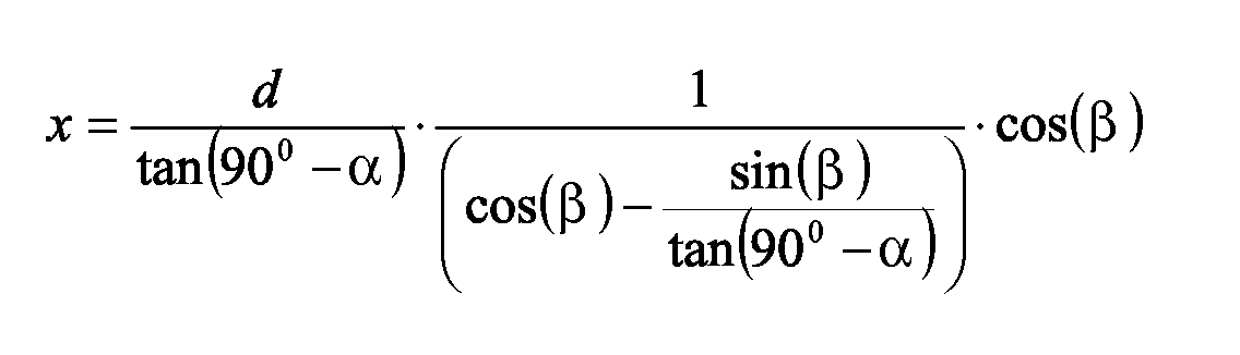
Bei vorgegebener Zeilennummer (Winkel β), Abstrahlwinkel α
und bekanntem Abstand zwischen Kamera K und Laserpointer LP
(gleich d), ergibt sich die Entfernung x des Objektes OB aus
der folgenden Gleichung:
Claims (4)
dadurch gekennzeichnet dass
characterized in that
dadurch gekennzeichnet dass
characterized in that
gekennzeichnet durch
marked by
gekennzeichnet durch
marked by
Applications Claiming Priority (2)
| Application Number | Priority Date | Filing Date | Title |
|---|---|---|---|
| DE10354555 | 2003-11-21 | ||
| DE10354555 | 2003-11-21 |
Publications (2)
| Publication Number | Publication Date |
|---|---|
| EP1533629A2 true EP1533629A2 (en) | 2005-05-25 |
| EP1533629A3 EP1533629A3 (en) | 2006-05-24 |
Family
ID=34428854
Family Applications (1)
| Application Number | Title | Priority Date | Filing Date |
|---|---|---|---|
| EP04103936A Withdrawn EP1533629A3 (en) | 2003-11-21 | 2004-08-17 | Distance measurement with a mobile terminal |
Country Status (1)
| Country | Link |
|---|---|
| EP (1) | EP1533629A3 (en) |
Cited By (10)
| Publication number | Priority date | Publication date | Assignee | Title |
|---|---|---|---|---|
| DE102011000678A1 (en) * | 2011-02-11 | 2012-08-16 | Analemma Apps Gmbh | Device for predetermining solar radiation at a defined location |
| CN103884334A (en) * | 2014-04-09 | 2014-06-25 | 中国人民解放军国防科学技术大学 | Moving target positioning method based on wide beam laser ranging and single camera |
| WO2015007799A2 (en) * | 2013-07-16 | 2015-01-22 | Leica Geosystems Ag | Laser tracker having target-seeking functionality |
| US10860029B2 (en) | 2016-02-15 | 2020-12-08 | RobArt GmbH | Method for controlling an autonomous mobile robot |
| US11175670B2 (en) | 2015-11-17 | 2021-11-16 | RobArt GmbH | Robot-assisted processing of a surface using a robot |
| US11188086B2 (en) | 2015-09-04 | 2021-11-30 | RobArtGmbH | Identification and localization of a base station of an autonomous mobile robot |
| US11550054B2 (en) | 2015-06-18 | 2023-01-10 | RobArtGmbH | Optical triangulation sensor for distance measurement |
| US11709489B2 (en) | 2017-03-02 | 2023-07-25 | RobArt GmbH | Method for controlling an autonomous, mobile robot |
| US11768494B2 (en) | 2015-11-11 | 2023-09-26 | RobArt GmbH | Subdivision of maps for robot navigation |
| US11789447B2 (en) | 2015-12-11 | 2023-10-17 | RobArt GmbH | Remote control of an autonomous mobile robot |
Citations (4)
| Publication number | Priority date | Publication date | Assignee | Title |
|---|---|---|---|---|
| US4660970A (en) * | 1983-11-25 | 1987-04-28 | Carl-Zeiss-Stiftung | Method and apparatus for the contact-less measuring of objects |
| EP0422249A1 (en) * | 1989-04-19 | 1991-04-17 | Fanuc Ltd. | Optical distance sensor |
| US5487669A (en) * | 1993-03-09 | 1996-01-30 | Kelk; George F. | Mobility aid for blind persons |
| WO2004036246A1 (en) * | 2002-10-18 | 2004-04-29 | Peter Stevrin | Mobile phone with laser range finder |
-
2004
- 2004-08-17 EP EP04103936A patent/EP1533629A3/en not_active Withdrawn
Patent Citations (4)
| Publication number | Priority date | Publication date | Assignee | Title |
|---|---|---|---|---|
| US4660970A (en) * | 1983-11-25 | 1987-04-28 | Carl-Zeiss-Stiftung | Method and apparatus for the contact-less measuring of objects |
| EP0422249A1 (en) * | 1989-04-19 | 1991-04-17 | Fanuc Ltd. | Optical distance sensor |
| US5487669A (en) * | 1993-03-09 | 1996-01-30 | Kelk; George F. | Mobility aid for blind persons |
| WO2004036246A1 (en) * | 2002-10-18 | 2004-04-29 | Peter Stevrin | Mobile phone with laser range finder |
Cited By (16)
| Publication number | Priority date | Publication date | Assignee | Title |
|---|---|---|---|---|
| DE102011000678A1 (en) * | 2011-02-11 | 2012-08-16 | Analemma Apps Gmbh | Device for predetermining solar radiation at a defined location |
| CN105452806B (en) * | 2013-07-16 | 2018-06-19 | 莱卡地球系统公开股份有限公司 | There is the laser tracker of goal seeking |
| WO2015007799A2 (en) * | 2013-07-16 | 2015-01-22 | Leica Geosystems Ag | Laser tracker having target-seeking functionality |
| WO2015007799A3 (en) * | 2013-07-16 | 2015-04-30 | Leica Geosystems Ag | Laser tracker having target-seeking functionality |
| CN105452806A (en) * | 2013-07-16 | 2016-03-30 | 莱卡地球系统公开股份有限公司 | Laser tracker having target-seeking functionality |
| US10048379B2 (en) | 2013-07-16 | 2018-08-14 | Leica Geosystems Ag | Laser tracker having target-seeking functionality |
| CN103884334B (en) * | 2014-04-09 | 2016-06-01 | 中国人民解放军国防科学技术大学 | Based on the moving target localization method of broad beam laser ranging and single camera |
| CN103884334A (en) * | 2014-04-09 | 2014-06-25 | 中国人民解放军国防科学技术大学 | Moving target positioning method based on wide beam laser ranging and single camera |
| US11550054B2 (en) | 2015-06-18 | 2023-01-10 | RobArtGmbH | Optical triangulation sensor for distance measurement |
| US11188086B2 (en) | 2015-09-04 | 2021-11-30 | RobArtGmbH | Identification and localization of a base station of an autonomous mobile robot |
| US11768494B2 (en) | 2015-11-11 | 2023-09-26 | RobArt GmbH | Subdivision of maps for robot navigation |
| US11175670B2 (en) | 2015-11-17 | 2021-11-16 | RobArt GmbH | Robot-assisted processing of a surface using a robot |
| US11789447B2 (en) | 2015-12-11 | 2023-10-17 | RobArt GmbH | Remote control of an autonomous mobile robot |
| US10860029B2 (en) | 2016-02-15 | 2020-12-08 | RobArt GmbH | Method for controlling an autonomous mobile robot |
| US11709497B2 (en) | 2016-02-15 | 2023-07-25 | RobArt GmbH | Method for controlling an autonomous mobile robot |
| US11709489B2 (en) | 2017-03-02 | 2023-07-25 | RobArt GmbH | Method for controlling an autonomous, mobile robot |
Also Published As
| Publication number | Publication date |
|---|---|
| EP1533629A3 (en) | 2006-05-24 |
Similar Documents
| Publication | Publication Date | Title |
|---|---|---|
| EP2495524B1 (en) | Method and device for displaying a three-dimensional view of the surface of a viewed object | |
| US9818039B2 (en) | Method and device for automatically identifying a point of interest in a depth measurement on a viewed object | |
| US20150276392A1 (en) | Graphical feedback during 3d scanning operations for obtaining optimal scan resolution | |
| DE102010015566B4 (en) | Method and system for measuring reflective surfaces | |
| EP1926049B1 (en) | Method for correcting a volume mapping equation for determining a velocity field for particles in a volume | |
| EP2886043A1 (en) | Method for continuing recordings to detect three-dimensional geometries of objects | |
| EP3557523A1 (en) | Method for generating a correcting model of a camera for correcting an imaging error | |
| EP2225533A1 (en) | Method for geo-referencing of optical remote sensing images | |
| JP6937642B2 (en) | Surface evaluation method and surface evaluation device | |
| DE102017211377B4 (en) | Method and device for optical surface measurement of a measurement object | |
| EP3548838B1 (en) | Wire rope measuring device and wire rope measuring method | |
| DE102016203377A1 (en) | Laser projection system with video overlay | |
| EP1533629A2 (en) | Distance measurement with a mobile terminal | |
| DE102017102227A1 (en) | Method and device for automatic identification of a point of interest in a depth measurement on a viewed object | |
| DE102004026357A1 (en) | Coordinate measuring and object scanning system uses X-ray source and X-ray sensors for primary scan and tactile and/or optical secondary mechanism movable in X, Y and Z directions for secondary scan | |
| EP3115738B1 (en) | Optoelectronic measuring device and method for fault detection | |
| DE102009032771A1 (en) | Measuring device for three-dimensional optical measurement of object, has image evaluation unit optically measuring object by evaluating images from reference mark image recording units for photogrametric determination of marks coordinates | |
| DE102013001897A1 (en) | Method for determining biometric data of limb e.g. human foot, involves providing image acquisition generated by orientation sensor together with image analysis process data for determining measurement data and biometric data | |
| DE102013211492A1 (en) | Determination of a measurement error | |
| US6618689B2 (en) | Method for the non-destructive inspection of wall strength | |
| EP0920642A1 (en) | 3d ultrasound recording device | |
| DE102007032471A1 (en) | Position determining method for e.g. on-board camera system, involves establishing representation function specifying representation of object points, and determining unknown parameters of function using numerical resolution technique | |
| DE102010004233B3 (en) | Method for determining position of camera system with respect to display, involves determining geometric dimensions of object and calibration element, and determining fixed spatial relation of calibration element to object | |
| JPS6256814A (en) | Calibration system for three-dimensional position measuring camera | |
| CN107424164B (en) | A kind of Image Edge-Detection Accuracy Assessment |
Legal Events
| Date | Code | Title | Description |
|---|---|---|---|
| PUAI | Public reference made under article 153(3) epc to a published international application that has entered the european phase |
Free format text: ORIGINAL CODE: 0009012 |
|
| AK | Designated contracting states |
Kind code of ref document: A2 Designated state(s): AT BE BG CH CY CZ DE DK EE ES FI FR GB GR HU IE IT LI LU MC NL PL PT RO SE SI SK TR |
|
| AX | Request for extension of the european patent |
Extension state: AL HR LT LV MK |
|
| PUAL | Search report despatched |
Free format text: ORIGINAL CODE: 0009013 |
|
| AK | Designated contracting states |
Kind code of ref document: A3 Designated state(s): AT BE BG CH CY CZ DE DK EE ES FI FR GB GR HU IE IT LI LU MC NL PL PT RO SE SI SK TR |
|
| AX | Request for extension of the european patent |
Extension state: AL HR LT LV MK |
|
| AKX | Designation fees paid | ||
| STAA | Information on the status of an ep patent application or granted ep patent |
Free format text: STATUS: THE APPLICATION IS DEEMED TO BE WITHDRAWN |
|
| 18D | Application deemed to be withdrawn |
Effective date: 20061125 |
|
| REG | Reference to a national code |
Ref country code: DE Ref legal event code: 8566 |