EP1532996A1 - Non grinded needle tip-geometry for an injection needle - Google Patents
Non grinded needle tip-geometry for an injection needle Download PDFInfo
- Publication number
- EP1532996A1 EP1532996A1 EP03388077A EP03388077A EP1532996A1 EP 1532996 A1 EP1532996 A1 EP 1532996A1 EP 03388077 A EP03388077 A EP 03388077A EP 03388077 A EP03388077 A EP 03388077A EP 1532996 A1 EP1532996 A1 EP 1532996A1
- Authority
- EP
- European Patent Office
- Prior art keywords
- needle
- needle shaft
- tip
- bevels
- injection needle
- Prior art date
- Legal status (The legal status is an assumption and is not a legal conclusion. Google has not performed a legal analysis and makes no representation as to the accuracy of the status listed.)
- Withdrawn
Links
- 238000002347 injection Methods 0.000 title claims abstract description 23
- 239000007924 injection Substances 0.000 title claims abstract description 23
- 238000005520 cutting process Methods 0.000 claims abstract description 26
- 230000007704 transition Effects 0.000 claims abstract description 7
- 238000000034 method Methods 0.000 claims description 8
- 238000004519 manufacturing process Methods 0.000 claims description 2
- 230000035515 penetration Effects 0.000 abstract description 12
- 239000012530 fluid Substances 0.000 abstract description 8
- 241000124008 Mammalia Species 0.000 abstract description 4
- 230000000740 bleeding effect Effects 0.000 abstract description 4
- 230000036407 pain Effects 0.000 description 5
- NOESYZHRGYRDHS-UHFFFAOYSA-N insulin Chemical compound N1C(=O)C(NC(=O)C(CCC(N)=O)NC(=O)C(CCC(O)=O)NC(=O)C(C(C)C)NC(=O)C(NC(=O)CN)C(C)CC)CSSCC(C(NC(CO)C(=O)NC(CC(C)C)C(=O)NC(CC=2C=CC(O)=CC=2)C(=O)NC(CCC(N)=O)C(=O)NC(CC(C)C)C(=O)NC(CCC(O)=O)C(=O)NC(CC(N)=O)C(=O)NC(CC=2C=CC(O)=CC=2)C(=O)NC(CSSCC(NC(=O)C(C(C)C)NC(=O)C(CC(C)C)NC(=O)C(CC=2C=CC(O)=CC=2)NC(=O)C(CC(C)C)NC(=O)C(C)NC(=O)C(CCC(O)=O)NC(=O)C(C(C)C)NC(=O)C(CC(C)C)NC(=O)C(CC=2NC=NC=2)NC(=O)C(CO)NC(=O)CNC2=O)C(=O)NCC(=O)NC(CCC(O)=O)C(=O)NC(CCCNC(N)=N)C(=O)NCC(=O)NC(CC=3C=CC=CC=3)C(=O)NC(CC=3C=CC=CC=3)C(=O)NC(CC=3C=CC(O)=CC=3)C(=O)NC(C(C)O)C(=O)N3C(CCC3)C(=O)NC(CCCCN)C(=O)NC(C)C(O)=O)C(=O)NC(CC(N)=O)C(O)=O)=O)NC(=O)C(C(C)CC)NC(=O)C(CO)NC(=O)C(C(C)O)NC(=O)C1CSSCC2NC(=O)C(CC(C)C)NC(=O)C(NC(=O)C(CCC(N)=O)NC(=O)C(CC(N)=O)NC(=O)C(NC(=O)C(N)CC=1C=CC=CC=1)C(C)C)CC1=CN=CN1 NOESYZHRGYRDHS-UHFFFAOYSA-N 0.000 description 4
- 230000008569 process Effects 0.000 description 4
- 239000003814 drug Substances 0.000 description 3
- 229940079593 drug Drugs 0.000 description 3
- 230000037324 pain perception Effects 0.000 description 3
- 102000004877 Insulin Human genes 0.000 description 2
- 108090001061 Insulin Proteins 0.000 description 2
- 206010012601 diabetes mellitus Diseases 0.000 description 2
- 229940125396 insulin Drugs 0.000 description 2
- 230000000149 penetrating effect Effects 0.000 description 2
- 210000001519 tissue Anatomy 0.000 description 2
- 230000009466 transformation Effects 0.000 description 2
- 238000000844 transformation Methods 0.000 description 2
- 230000015572 biosynthetic process Effects 0.000 description 1
- 230000008878 coupling Effects 0.000 description 1
- 238000010168 coupling process Methods 0.000 description 1
- 238000005859 coupling reaction Methods 0.000 description 1
- 238000001647 drug administration Methods 0.000 description 1
- 230000000694 effects Effects 0.000 description 1
- 230000006870 function Effects 0.000 description 1
- 230000003116 impacting effect Effects 0.000 description 1
- 208000014674 injury Diseases 0.000 description 1
- 238000003698 laser cutting Methods 0.000 description 1
- 238000002483 medication Methods 0.000 description 1
- 206010033675 panniculitis Diseases 0.000 description 1
- 239000007929 subcutaneous injection Substances 0.000 description 1
- 238000010254 subcutaneous injection Methods 0.000 description 1
- 210000004304 subcutaneous tissue Anatomy 0.000 description 1
- 230000008733 trauma Effects 0.000 description 1
Images


Classifications
-
- A—HUMAN NECESSITIES
- A61—MEDICAL OR VETERINARY SCIENCE; HYGIENE
- A61M—DEVICES FOR INTRODUCING MEDIA INTO, OR ONTO, THE BODY; DEVICES FOR TRANSDUCING BODY MEDIA OR FOR TAKING MEDIA FROM THE BODY; DEVICES FOR PRODUCING OR ENDING SLEEP OR STUPOR
- A61M5/00—Devices for bringing media into the body in a subcutaneous, intra-vascular or intramuscular way; Accessories therefor, e.g. filling or cleaning devices, arm-rests
- A61M5/178—Syringes
- A61M5/31—Details
- A61M5/32—Needles; Details of needles pertaining to their connection with syringe or hub; Accessories for bringing the needle into, or holding the needle on, the body; Devices for protection of needles
- A61M5/3286—Needle tip design, e.g. for improved penetration
-
- B—PERFORMING OPERATIONS; TRANSPORTING
- B23—MACHINE TOOLS; METAL-WORKING NOT OTHERWISE PROVIDED FOR
- B23K—SOLDERING OR UNSOLDERING; WELDING; CLADDING OR PLATING BY SOLDERING OR WELDING; CUTTING BY APPLYING HEAT LOCALLY, e.g. FLAME CUTTING; WORKING BY LASER BEAM
- B23K26/00—Working by laser beam, e.g. welding, cutting or boring
- B23K26/08—Devices involving relative movement between laser beam and workpiece
- B23K26/0823—Devices involving rotation of the workpiece
-
- B—PERFORMING OPERATIONS; TRANSPORTING
- B23—MACHINE TOOLS; METAL-WORKING NOT OTHERWISE PROVIDED FOR
- B23K—SOLDERING OR UNSOLDERING; WELDING; CLADDING OR PLATING BY SOLDERING OR WELDING; CUTTING BY APPLYING HEAT LOCALLY, e.g. FLAME CUTTING; WORKING BY LASER BEAM
- B23K26/00—Working by laser beam, e.g. welding, cutting or boring
- B23K26/36—Removing material
- B23K26/38—Removing material by boring or cutting
-
- A—HUMAN NECESSITIES
- A61—MEDICAL OR VETERINARY SCIENCE; HYGIENE
- A61M—DEVICES FOR INTRODUCING MEDIA INTO, OR ONTO, THE BODY; DEVICES FOR TRANSDUCING BODY MEDIA OR FOR TAKING MEDIA FROM THE BODY; DEVICES FOR PRODUCING OR ENDING SLEEP OR STUPOR
- A61M5/00—Devices for bringing media into the body in a subcutaneous, intra-vascular or intramuscular way; Accessories therefor, e.g. filling or cleaning devices, arm-rests
- A61M5/42—Devices for bringing media into the body in a subcutaneous, intra-vascular or intramuscular way; Accessories therefor, e.g. filling or cleaning devices, arm-rests having means for desensitising skin, for protruding skin to facilitate piercing, or for locating point where body is to be pierced
- A61M5/422—Desensitising skin
-
- B—PERFORMING OPERATIONS; TRANSPORTING
- B23—MACHINE TOOLS; METAL-WORKING NOT OTHERWISE PROVIDED FOR
- B23K—SOLDERING OR UNSOLDERING; WELDING; CLADDING OR PLATING BY SOLDERING OR WELDING; CUTTING BY APPLYING HEAT LOCALLY, e.g. FLAME CUTTING; WORKING BY LASER BEAM
- B23K2101/00—Articles made by soldering, welding or cutting
- B23K2101/04—Tubular or hollow articles
- B23K2101/06—Tubes
Definitions
- the present invention relates to an injection needle for injecting or retracting fluid through the skin of a mammal body and more particularly to non-grinded needle tip-geometry for an injection needle for a reduced penetration force and reduced bleeding
- This invention further relates to a method of sharpening the needle point.
- Conventional hypodermic needles typically include a hollow shaft having a fluid conducting lumen which is secured to a hub and a piercing part that is a more or less a sharply angled wedge at the distal end of the hypodermic needle.
- the hub is connected to a fluid delivery device such as a syringe such that the hollow shaft forms a channel from beneath the skin of the mammal body to the delivery device through which the fluid can be transported.
- a hypodermic needle is typically used for performing the function of injecting or retracting drugs, medications fluid or like into the subcutaneous tissue.
- Some drugs such as insulin are self administered, and a typical diabetic person will require subcutaneous injections of insulin several times during the course of the day.
- a typical diabetic person will require subcutaneous injections of insulin several times during the course of the day.
- Recent studies have indicated that people who inject themselves experience less pain when using a thin needle shaft i.e. a needle shaft having a little outside diameter.
- injection needles with a very thin needle shaft are preferred among people suffering from diabetes.
- the geometry of the tip also influences on the pain perception. It is generally recognized that by reducing needle penetration force, the user will experience less pain, making the injection more comfortable.
- the needle face is characterized by a pair of bevels which intersect with the main facet.
- the heel portion of the needle face includes an external recess, which merges with a smoothly rounded surface or edge portion of the lumen opening.
- US patent No. 2409979 for a hypodermic needle is also intended to reduce the pain experienced by the patient as the needle penetrates the tissue.
- a five-beveled needle shaft is disclosed in US 3308822.
- the tip geometry disclosed is also made by grinding the distal end of the needle shaft.
- the needle tip is formed by grinding two additional bevels on traditional three-beveled needle tip geometry on the side away from the three bevels.
- the needle tip geometry of this patent greatly reduces penetration force and immediately following the initial penetration, the skin and underlying flesh is cleanly cut along three substantially straight lines radiating from the initial piercing point substantially in the form of the letter 'Y'.
- a multi beveled needle tip is a more continuous needle tip geometry though a high number of bevels tends to have a more sharp and delicate tip.
- the multi beveled needle-point includes a primary bevel, a pair of tip bevels and a pair of middle bevels. It has been surmised by the inventors that a primary reason that a patient experiences pain when the needle is inserted is that a portion of the needle point 'catches' on the skin or flesh as the needle penetrates. It has been reasoned that one cause of the needle catching the skin or flesh is due to the height of the 'intercept' established at the transition between different bevels forming the needle -point.
- the skin-piercing tip of the needle shaft becomes extremely sharp pointed. Further, the grinding process results in transitions on the piercing edges that eventually affect the pain perception. Also, the said grinding transitions do not afford a uniform and continuous piercing edge. The ill effects of grinding are present on the needle tip.
- a drawback with very sharp pointed tip is the possibility of accidental deforming the very tip either during the manufacturing of the injection needle or by the user when handling the injection needle.
- a very sharp needle and delicate tip such as the five-beveled tip geometry is more exposed to deformations than a not so sharp needle such as a three beveled needle tip geometry.
- a typical deformity called hook (2) can occur on the very tip of a sharp pointed needle (1) if the tip accidentally is bumped into an object.
- the very tip can form a hook similar to what is known from the arrow shaped tip of a fishing hook. This influences strongly on the pain perception during injection since the hook on the needle tip will cause severe pain when removing the injection needle from the skin of the user.
- a needle structure has a non-grinded tip which is cut by a laser and comprises of a needle shaft having a centrally located bore disposed along a longitudinal axis connected to a hub by connecting means.
- the sharpened distal end of the needle shaft has an exit port and two bevels surrounding the exit port.
- the bevels converge into a tip at the distal end to form a cutting edge and at the proximal end into a heel.
- the bevels, cutting edge and heel together form the piercing edge that is sharp and continuous without any grinding transitions.
- the term 'distal' refers to a direction farthest from the practitioner and the term 'proximal' refers to a direction closest to the practitioner.
- FIG. 1 there is shown a sharp pointed needle (1) with the formation of a hook (2) at the needle tip.
- a multi-beveled needle tip geometry shown in Figure 2 in accordance with the prior art is formed through a plurality of individual bevels characterized by a primary bevel (4a), a pair of middle bevels (5a, 5b) and a pair of tip bevels (6a, 6b).
- the middle and tip bevels (5a, 6a) meet at an intersect (7a) demarcating the respective planes at which the middle and tip bevels are formed.
- adjacent middle and tip bevels (5b, 6b) meet at intersect (7b).
- the needle shaft (8) is divided into a first part (8a) located outside the hub (9) for penetrating the skin of the mammal body and a second part (8b) located within the hub for penetrating a cartridge (not shown) containing the fluid to be injected.
- the hub (9) is provided with means (10) for connecting the hub to an injection pen.
- the first part (8a) is usually provided with a sharpened distal end (11) for providing an optimal penetration of the skin.
- the second part (8b) may be provided with a sharpened end as well.
- Figure 5 discloses an alternate embodiment for connecting the needle shaft (8)to a somewhat different hub (9).
- This hub is particularly suitable for hypodermic syringes and is usually connected to the syringe by a traditional luer coupling.
- the needle shaft (8) has a centrally located bore disposed along a central axis (12) for allowing fluid to flow through the needle shaft (8).
- the wall thickness of the needle shaft is defined as the difference between the diameter of the bore and the outside diameter of the needle shaft. ISO 9626 standard usually defines these dimensions.
- the sharpened distal end (11) of the needle shaft (8) has an exit port (13) shaped as an ellipse with a major axis (14) parallel with the central axis (12) and a minor axis (15) perpendicular to the central axis (12).
- the exit port is surrounded by two bevels (16, 17) that converge into a tip formed as a cutting edge (18) at the most distal end of the major axis (14) and converge into a heel (19) at the opposite end of the longer axis (14) of the exit port (13).
- the exit port(13) thus formed comprises a cutting edge (18), a pair of bevels (16, 17) and a heel (19) which together form the piercing edge of the needle tip.
- Laser is used for the cutting operation results which results in a uniform continuous and well-rounded piercing edge of the exit port.
- the cutting edge of the needle shaft though sharp and pointed affording a lower penetration force is also robust and less susceptible to accidental deformation. Further, the piercing edge is free from grinding transitions as occasioned by prior art.
- Bevels 16 and 17 are equal in length and angle and are symmetrically formed on either side of the heel 19 and cutting edge 18.
- the cutting edge as shown in figure 6 may be perpendicular to the central axis or may be an angle to the axis.
- the angle of inclination is preferably in the range of 45 and 90 degrees.
- a non-grinded needle tip for injection can be made by securing the needle shaft in a movable tool (20) comprising a pair of jaws (21, 22) such that needle shaft moves with the tool.
- the tool is capable of longitudinal movement as well as rotation.
- a laser beam (23) is directed from a laser emitter (24) onto the surface of the needle shaft (8).
- the laser beam (23) and the laser emitter (24) is locked in a stationary position throughout the cutting such that the laser beam (23) is perpendicular to the central axis (12) of the needle shaft (8).
- the impact angle between the laser beam (23) and the needle shaft (8) is 90 degrees.
- the laser beam (23) is directed onto the most distal end of the needle shaft (8).
- the laser beam (23) cuts through the wall of the needle shaft (8) forming an opening in the needle shaft (8).
- the movable tool (21) and the needle shaft (8) along with it is moved longitudinally parallel with the central axis of the bore in the direction indicated by the first arrow (25) (towards left as seen in the plane of the figure 9).
- the needle shaft (8) is rotated.
- the rotation is first anti clockwise in the direction indicated by the arrow (26) until the shaft has been rotated 90 degrees to one side and then the rotation is clockwise for another 90 degrees as indicated by the arrow (27). This movement cuts the first bevel 16.
- the needle shaft (8) When the shaft is rotated back to its initial rotational position with the laser beam (23) impacting the surface of shaft at the most proximal end of the major axis (14), the needle shaft (8) is continuously rotated clockwise as indicated by the arrow (27). During this continued clockwise rotation the needle shaft (8) is moved longitudinally in the direction as indicated by the arrow (28) (towards right as seen in the plane of figure 9). Once the needle shaft has been rotated 90 degrees in the clockwise direction from initial position, the rotational direction is changed to anticlockwise and the laser beam (23) will encounter the initial cut at the most distal end of the major axis (14). This movement finalizes the second bevel (17). This predetermined movement of the movable tool and the needle shaft will form the exit port (13) with a smooth continuous piercing edge as disclosed in the figures 3, 6 and 8.
- the two bevels (16, 17) meet at the most distal end of the major axis (14) as a cutting edge (18) and at the most proximal end as the heel (19).
- the cutting edge achieved by this laser cutting process is sharp, pointed and at the same time robust.
- the edges of the exit port and the cutting edge, together forming a piercing edge, realized by the above process are smooth, continuous, uniform and without grinding transformations.
- Such a needle tip offers better drug administration. Further, it is believed that the needle tip as disclosed in the preceding paragraphs results in reduced bleeding and also a reduced penetration force at the heel.
- the laser emitter (24) can be tilted during the movement of the needle shaft (8) such that the impact angle 80 can be different from 90 degrees.
- the laser emitter is preferably tilted when cutting at the most distal end of the major axis (14).
- the cutting edge (18) can be provided at an angle ' ⁇ ' with the central axis.
- the angle ' ⁇ ' is preferably between 45 and 90 degrees.
- the opposite angle formed between the cutting edge (18) and an axis perpendicular to the longitudinal axis is preferably between 0 and 45 degrees.
- the angle ' ⁇ ' preferably slopes towards the needle shaft 8 as disclosed in figure 4. In yet another embodiment the angle ' ⁇ ' could slope away from the needle shaft 8.
- the present invention is not limited to the specific embodiments herein shown. Thus variations may be made within the scope and spirit of the accompanying claims without sacrificing the principal advantages of the invention.
- Preferably only the very distal part of the tip needs to be made as a non-grinded tip in order to obtain a cutting edge (18).
- the proximal part end of the tip could be made in a traditional manner i.e. by grinding.
Abstract
The present invention relates to an injection needle (1) for
injecting or retracting fluid through the skin of a mammal body and more
particularly to non-grinded needle tip-geometry for an injection needle
(1) for a reduced penetration force and reduced bleeding. The injection
needle (1) comprises of a needle shaft (8) having a centrally located
bore disposed along a longitudinal axis (12) connected to a hub (9) by
connecting means. The sharpened distal end (11) of the needle shaft (8)
has an exit port (13) and two bevels (16,17) surrounding the exit port
(13). The bevels (16,17) converge into a tip at the distal end to form a
cutting edge (18) and at the proximal end into a heel (19). The bevels
(16,17), cutting edge (18) and heel (19) together form the piercing edge
that is sharp and continuous without any grinding transitions.
Description
- The present invention relates to an injection needle for injecting or retracting fluid through the skin of a mammal body and more particularly to non-grinded needle tip-geometry for an injection needle for a reduced penetration force and reduced bleeding
- This invention further relates to a method of sharpening the needle point.
- Conventional hypodermic needles typically include a hollow shaft having a fluid conducting lumen which is secured to a hub and a piercing part that is a more or less a sharply angled wedge at the distal end of the hypodermic needle. The hub is connected to a fluid delivery device such as a syringe such that the hollow shaft forms a channel from beneath the skin of the mammal body to the delivery device through which the fluid can be transported.
- A hypodermic needle is typically used for performing the function of injecting or retracting drugs, medications fluid or like into the subcutaneous tissue.
- Some drugs, such as insulin are self administered, and a typical diabetic person will require subcutaneous injections of insulin several times during the course of the day. Recent studies have indicated that people who inject themselves experience less pain when using a thin needle shaft i.e. a needle shaft having a little outside diameter. In order to reduce the discomfort of having to inject oneself several times a day, injection needles with a very thin needle shaft are preferred among people suffering from diabetes.
- Besides the diameter of the needle, the geometry of the tip also influences on the pain perception. It is generally recognized that by reducing needle penetration force, the user will experience less pain, making the injection more comfortable.
- Attempts have been made to minimize the needle penetration force necessary for urging the tip of the needle shaft through the skin of the user.
- In US patent no. 3071135, which is incorporated as if fully set forth herein, the needle face is characterized by a pair of bevels which intersect with the main facet. The heel portion of the needle face includes an external recess, which merges with a smoothly rounded surface or edge portion of the lumen opening.
- US patent No. 2409979 for a hypodermic needle is also intended to reduce the pain experienced by the patient as the needle penetrates the tissue.
- In US patent No. 2560162, an additional pair of forward side bevels is provided. In this patent, the provision of the recess prevents or minimizes the severing of a plug from a layer (s) being pierced by the needle.
- A five-beveled needle shaft is disclosed in US 3308822. The tip geometry disclosed is also made by grinding the distal end of the needle shaft. The needle tip is formed by grinding two additional bevels on traditional three-beveled needle tip geometry on the side away from the three bevels. The needle tip geometry of this patent greatly reduces penetration force and immediately following the initial penetration, the skin and underlying flesh is cleanly cut along three substantially straight lines radiating from the initial piercing point substantially in the form of the letter 'Y'.
- A result of grinding, a multi beveled needle tip is a more continuous needle tip geometry though a high number of bevels tends to have a more sharp and delicate tip.
- Another five-beveled needle tip geometry as disclosed in US 5752942 is an example of an attempt to lower the penetration force. The multi beveled needle-point includes a primary bevel, a pair of tip bevels and a pair of middle bevels. It has been surmised by the inventors that a primary reason that a patient experiences pain when the needle is inserted is that a portion of the needle point 'catches' on the skin or flesh as the needle penetrates. It has been reasoned that one cause of the needle catching the skin or flesh is due to the height of the 'intercept' established at the transition between different bevels forming the needle -point.
- It is here believed that reducing the height of the intercept between the bevels making up the needle tip geometry will form a more continuous and unitary tip geometry that would require less penetration force.
- In US patent nos. 3,308,822 and 5,752,942, the bevels are formed by conventional processes such as grinding.
- When grinding such needle geometry, the skin-piercing tip of the needle shaft becomes extremely sharp pointed. Further, the grinding process results in transitions on the piercing edges that eventually affect the pain perception. Also, the said grinding transitions do not afford a uniform and continuous piercing edge. The ill effects of grinding are present on the needle tip.
- A drawback with very sharp pointed tip is the possibility of accidental deforming the very tip either during the manufacturing of the injection needle or by the user when handling the injection needle.
- Also, a very sharp needle and delicate tip such as the five-beveled tip geometry is more exposed to deformations than a not so sharp needle such as a three beveled needle tip geometry.
- As shown in figure 1, a typical deformity called hook (2) can occur on the very tip of a sharp pointed needle (1) if the tip accidentally is bumped into an object. In the worst case the very tip can form a hook similar to what is known from the arrow shaped tip of a fishing hook. This influences strongly on the pain perception during injection since the hook on the needle tip will cause severe pain when removing the injection needle from the skin of the user.
- Accordingly, it is the object of the present invention to provide a new and an improved needle structure, which is capable of easier penetration into the patients tissue with minimum trauma with reduced bleeding
- It is also an object of the present invention to provide for a needle structure with a robust needle point geometry. It is yet another object of the present invention to provide an injection needle with a piercing edge free from grinding transformations. A further object of the present invention is to provide a needle point geometry which is not too sharp pointed at the tip so as to avoid accidental deformation.
- To overcome the drawbacks of the prior art the present invention provides for non-grinded needle tip for needles. Briefly described, a needle structure according to the present invention has a non-grinded tip which is cut by a laser and comprises of a needle shaft having a centrally located bore disposed along a longitudinal axis connected to a hub by connecting means. The sharpened distal end of the needle shaft has an exit port and two bevels surrounding the exit port. The bevels converge into a tip at the distal end to form a cutting edge and at the proximal end into a heel.
- The bevels, cutting edge and heel together form the piercing edge that is sharp and continuous without any grinding transitions.
- The accompanying drawings illustrate preferred embodiments of the invention and, together with the following detailed description, serve to explain the principles of the invention.
- Figure 1 illustrates the tip of a sharp pointed needle with a typical deformity of conventional hypodermic needles.
- Figure 2 illustrates multi-beveled needle tip geometry in accordance with prior art as shown in figure 5 of US patent 5752942.
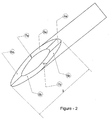
- Figure 3 illustrates a perspective view of a non-grinded needle tip in accordance with the present invention.
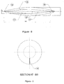
- Figure 4 illustrate a sectional side view of an embodiment of a needle in accordance with the present invention.
- Figure 5 illustrate a sectional side view of an alternate embodiment of a needle in accordance with the present invention.
- Figure 6 illustrates a sectional side view of the distal end of a needle according to the invention.
- Figure 7 illustrates a sectional view along the line A-A in figure 6.
- Figure 8 illustrates a sectional top view of the needle in figure 3.
- Figure 9 illustrates shows a sectional view along the line B-B in figure 6.
- Figure 10 shows a schematic view of an embodiment of a method in accordance with the present invention .
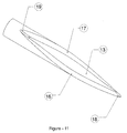
- Figure 11 shows a perspective of an embodiment of the needle in accordance with the present invention.
- Figure 12 shows a sectional side view of the needle in figure 11.
-
- It will be understood by those skilled in the art that the foregoing general description and the following detailed description are exemplary and explanatory of the invention and are not intended to be restrictive thereof.
- Through out the patent specification, a convention employed is that in the appended drawings, like numerals denote like components.
- At the outset it is appropriate to mention that the term 'distal' refers to a direction farthest from the practitioner and the term 'proximal' refers to a direction closest to the practitioner.
- Referring first to Figure 1, there is shown a sharp pointed needle (1) with the formation of a hook (2) at the needle tip.
- A multi-beveled needle tip geometry shown in Figure 2 in accordance with the prior art. The multi-beveled point (3) is formed through a plurality of individual bevels characterized by a primary bevel (4a), a pair of middle bevels (5a, 5b) and a pair of tip bevels (6a, 6b). The middle and tip bevels (5a, 6a) meet at an intersect (7a) demarcating the respective planes at which the middle and tip bevels are formed. Likewise, adjacent middle and tip bevels (5b, 6b) meet at intersect (7b).
- Turning to Figures 4 and 5, there is shown alternate embodiments for connecting the needle shaft to a hub. In figure 4, the needle shaft (8) is divided into a first part (8a) located outside the hub (9) for penetrating the skin of the mammal body and a second part (8b) located within the hub for penetrating a cartridge (not shown) containing the fluid to be injected. Further the hub (9) is provided with means (10) for connecting the hub to an injection pen. The first part (8a) is usually provided with a sharpened distal end (11) for providing an optimal penetration of the skin. The second part (8b) may be provided with a sharpened end as well.
- Figure 5 discloses an alternate embodiment for connecting the needle shaft (8)to a somewhat different hub (9). This hub is particularly suitable for hypodermic syringes and is usually connected to the syringe by a traditional luer coupling.
- The needle shaft (8) has a centrally located bore disposed along a central axis (12) for allowing fluid to flow through the needle shaft (8). The wall thickness of the needle shaft is defined as the difference between the diameter of the bore and the outside diameter of the needle shaft. ISO 9626 standard usually defines these dimensions.
- As shown in figures 6 and 8, the sharpened distal end (11) of the needle shaft (8) has an exit port (13) shaped as an ellipse with a major axis (14) parallel with the central axis (12) and a minor axis (15) perpendicular to the central axis (12). The exit port is surrounded by two bevels (16, 17) that converge into a tip formed as a cutting edge (18) at the most distal end of the major axis (14) and converge into a heel (19) at the opposite end of the longer axis (14) of the exit port (13). The exit port(13) thus formed comprises a cutting edge (18), a pair of bevels (16, 17) and a heel (19) which together form the piercing edge of the needle tip.
- Laser is used for the cutting operation results which results in a uniform continuous and well-rounded piercing edge of the exit port. As can be seen from figures 3, 6 and 8, the cutting edge of the needle shaft though sharp and pointed affording a lower penetration force is also robust and less susceptible to accidental deformation. Further, the piercing edge is free from grinding transitions as occasioned by prior art.
-
Bevels heel 19 and cuttingedge 18. - The cutting edge as shown in figure 6 may be perpendicular to the central axis or may be an angle to the axis. The angle of inclination is preferably in the range of 45 and 90 degrees.
- As shown in Figure 10, a non-grinded needle tip for injection can be made by securing the needle shaft in a movable tool (20) comprising a pair of jaws (21, 22) such that needle shaft moves with the tool. The tool is capable of longitudinal movement as well as rotation.
- A laser beam (23) is directed from a laser emitter (24) onto the surface of the needle shaft (8). The laser beam (23) and the laser emitter (24) is locked in a stationary position throughout the cutting such that the laser beam (23) is perpendicular to the central axis (12) of the needle shaft (8). The impact angle between the laser beam (23) and the needle shaft (8) is 90 degrees.
- Initially the laser beam (23) is directed onto the most distal end of the needle shaft (8). The laser beam (23) cuts through the wall of the needle shaft (8) forming an opening in the needle shaft (8). The movable tool (21) and the needle shaft (8) along with it is moved longitudinally parallel with the central axis of the bore in the direction indicated by the first arrow (25) (towards left as seen in the plane of the figure 9). During this longitudinal movement the needle shaft (8) is rotated. The rotation is first anti clockwise in the direction indicated by the arrow (26) until the shaft has been rotated 90 degrees to one side and then the rotation is clockwise for another 90 degrees as indicated by the arrow (27). This movement cuts the
first bevel 16. - When the shaft is rotated back to its initial rotational position with the laser beam (23) impacting the surface of shaft at the most proximal end of the major axis (14), the needle shaft (8) is continuously rotated clockwise as indicated by the arrow (27). During this continued clockwise rotation the needle shaft (8) is moved longitudinally in the direction as indicated by the arrow (28) (towards right as seen in the plane of figure 9). Once the needle shaft has been rotated 90 degrees in the clockwise direction from initial position, the rotational direction is changed to anticlockwise and the laser beam (23) will encounter the initial cut at the most distal end of the major axis (14). This movement finalizes the second bevel (17). This predetermined movement of the movable tool and the needle shaft will form the exit port (13) with a smooth continuous piercing edge as disclosed in the figures 3, 6 and 8.
- The two bevels (16, 17) meet at the most distal end of the major axis (14) as a cutting edge (18) and at the most proximal end as the heel (19). The cutting edge achieved by this laser cutting process is sharp, pointed and at the same time robust. The edges of the exit port and the cutting edge, together forming a piercing edge, realized by the above process are smooth, continuous, uniform and without grinding transformations. Such a needle tip offers better drug administration. Further, it is believed that the needle tip as disclosed in the preceding paragraphs results in reduced bleeding and also a reduced penetration force at the heel.
- In an alternate embodiment, as shown in figures 11 and 12, the laser emitter (24) can be tilted during the movement of the needle shaft (8) such that the
impact angle 80 can be different from 90 degrees. The laser emitter is preferably tilted when cutting at the most distal end of the major axis (14). In this way the cutting edge (18) can be provided at an angle 'α' with the central axis. The angle 'α' is preferably between 45 and 90 degrees. The opposite angle formed between the cutting edge (18) and an axis perpendicular to the longitudinal axis is preferably between 0 and 45 degrees. The angle 'α' preferably slopes towards theneedle shaft 8 as disclosed in figure 4. In yet another embodiment the angle 'α' could slope away from theneedle shaft 8. - It will readily be appreciated by those skilled in the art that the present invention is not limited to the specific embodiments herein shown. Thus variations may be made within the scope and spirit of the accompanying claims without sacrificing the principal advantages of the invention. Preferably only the very distal part of the tip needs to be made as a non-grinded tip in order to obtain a cutting edge (18). The proximal part end of the tip could be made in a traditional manner i.e. by grinding.
Claims (10)
- An injection needle comprising:a needle shaft (8) having a centrally located bore disposed along a longitudinal axis (12) connected to a hub (9), characterized in that,the sharpened distal end of the needle shaft (8) has an exit port (13),two bevels (16, 17) surrounding the exit port (13),the bevels (16, 17) converge into a tip at the distal end to form a cutting edge (18) and at the proximal end into a heel (19), the cutting edge (18) being at an angle 'α' with the longitudinal axis (12),the bevels (16, 17), cutting edge (18) and heel (19) together form a piercing edge, wherein at least the tip part of the piercing edge is sharp and continuous without any grinding transitions.
- An injection needle of claim 1, characterized in that, at least the tip part of the piercing edge is non-grinded.
- An injection needle of claim 1 or 2, characterized in that the exit port (13) has a major axis (14) parallel to the longitudinal axis (12) and a minor axis (15) perpendicular to the longitudinal axis (12) of the needle shaft (8).
- An injection needle of claim 1 to 3, characterized in that the angle 'α' is in the range of 45 ° to 90 °.
- An injection needle of claim 1 to 3, characterized in that the angle formed between the cutting edge and the axis perpendicular to the longitudinal axis (12) is in the range of 0-45 °.
- An injection needle of claim 4 or 5, characterized in that, the angle 'α' is approximately 90 °.
- An injection needle of claim 6, characterized in that, the height of the cutting edge (18) substantially equals the wall thickness of the needle shaft (8).
- A method of making an injection needle having a non-grinded tip comprising a pair of bevels (16, 17), a cutting edge (18) and a heel (19) forming an exit port (13), characterized by comprising the steps of:clamping the needle shaft (8) in a movable tool (20) that moves parallel to the longitudinal axis (12) of the needle shaft (8) and is capable of longitudinal as well as rotational movement,directing a laser beam (23) at the needle shaft (8) to make the first cut, andmoving the needle shaft (8) in a predetermined pattern.
- A method of claim 8, characterized by further comprising the steps of:longitudinally moving the needle shaft (8) in a first direction and simultaneously rotating the needle shaft by 90 degrees in a first rotational direction and in the opposite direction by 90 degrees such that the first bevel (16) is cut,longitudinally moving the needle shaft (8) in an opposite second direction while continuing rotation of the needle shaft (8) for another 90 degrees and in the first rotational direction for 90 degrees such that the laser beam (23) encounters the initial cut, thereby cutting the second bevel (17) and the cutting (18) edge between the first (16) and second (17) bevel at the distal end.
- A method of claim 9, characterized in that, the laser beam (23) is inclined to the central axis (12) of the needle shaft (8).
Priority Applications (5)
| Application Number | Priority Date | Filing Date | Title |
|---|---|---|---|
| EP03388077A EP1532996A1 (en) | 2003-11-20 | 2003-11-20 | Non grinded needle tip-geometry for an injection needle |
| JP2006540165A JP2007511300A (en) | 2003-11-20 | 2004-11-05 | Needle tip shape that does not depend on the polishing of the injection needle |
| EP04797426A EP1687050A1 (en) | 2003-11-20 | 2004-11-05 | Non grinded needle tip-geometry for an injection needle |
| PCT/DK2004/000764 WO2005049118A1 (en) | 2003-11-20 | 2004-11-05 | Non grinded needle tip-geometry for an injection needle |
| US11/435,116 US20070078415A1 (en) | 2003-11-20 | 2006-05-16 | Non grinded needle tip-geometry for an injection needle |
Applications Claiming Priority (1)
| Application Number | Priority Date | Filing Date | Title |
|---|---|---|---|
| EP03388077A EP1532996A1 (en) | 2003-11-20 | 2003-11-20 | Non grinded needle tip-geometry for an injection needle |
Publications (1)
| Publication Number | Publication Date |
|---|---|
| EP1532996A1 true EP1532996A1 (en) | 2005-05-25 |
Family
ID=34429602
Family Applications (2)
| Application Number | Title | Priority Date | Filing Date |
|---|---|---|---|
| EP03388077A Withdrawn EP1532996A1 (en) | 2003-11-20 | 2003-11-20 | Non grinded needle tip-geometry for an injection needle |
| EP04797426A Withdrawn EP1687050A1 (en) | 2003-11-20 | 2004-11-05 | Non grinded needle tip-geometry for an injection needle |
Family Applications After (1)
| Application Number | Title | Priority Date | Filing Date |
|---|---|---|---|
| EP04797426A Withdrawn EP1687050A1 (en) | 2003-11-20 | 2004-11-05 | Non grinded needle tip-geometry for an injection needle |
Country Status (4)
| Country | Link |
|---|---|
| US (1) | US20070078415A1 (en) |
| EP (2) | EP1532996A1 (en) |
| JP (1) | JP2007511300A (en) |
| WO (1) | WO2005049118A1 (en) |
Cited By (6)
| Publication number | Priority date | Publication date | Assignee | Title |
|---|---|---|---|---|
| WO2008132660A1 (en) * | 2007-04-25 | 2008-11-06 | Koninklijke Philips Electronics N.V. | Needle for mechanically assisted insertion |
| WO2009095184A1 (en) * | 2008-01-28 | 2009-08-06 | Roche Diagnostics Gmbh | Rapid blood expression and sampling |
| CN101357246B (en) * | 2008-09-24 | 2011-11-16 | 杨昌燕 | Safe medical needle head and processing method thereof |
| US8568422B2 (en) | 2008-09-01 | 2013-10-29 | Nigel Morlet | Cutting needle tip for surgical instrument |
| US9566189B2 (en) | 2011-08-03 | 2017-02-14 | Nigel Morlet | Grooved needle tip for surgical instrument |
| US9867736B2 (en) | 2010-03-29 | 2018-01-16 | Nigel Morlet | Needle tip for surgical instrument |
Families Citing this family (7)
| Publication number | Priority date | Publication date | Assignee | Title |
|---|---|---|---|---|
| WO2014046950A1 (en) | 2012-09-24 | 2014-03-27 | Enable Injections, Llc | Medication vial and injector assemblies and methods of use |
| WO2014204894A2 (en) | 2013-06-18 | 2014-12-24 | Enable Injections, Llc | Vial transfer and injection apparatus and method |
| EA034491B1 (en) * | 2014-11-28 | 2020-02-13 | Мед Италия Байомедика С.Р.Л. | Syringe and relative needle |
| CA3209663A1 (en) | 2014-12-11 | 2016-06-16 | Facet Technologies, Llc | Needle with multi-bevel tip geometry |
| US10070886B2 (en) | 2015-04-22 | 2018-09-11 | Medline Industries, Inc. | Method of harvesting tissue using sequential sections of a two dimensional array of needles |
| CN107921203B (en) * | 2015-07-30 | 2021-04-09 | 泰尔茂株式会社 | Medical puncture needle and method for manufacturing puncture needle |
| US10820893B2 (en) * | 2017-02-15 | 2020-11-03 | Cook Medical Technologies Llc | Endoscopic tri-point biopsy needle |
Citations (12)
| Publication number | Priority date | Publication date | Assignee | Title |
|---|---|---|---|---|
| US2409979A (en) | 1946-03-14 | 1946-10-22 | Ralph L Huber | Hypodermic needle |
| US2560162A (en) | 1950-02-10 | 1951-07-10 | Becton Dickinson Co | Needle structure |
| US3071135A (en) | 1960-01-27 | 1963-01-01 | Mfg Process Lab Inc | Hollow needle |
| US3289675A (en) * | 1961-12-08 | 1966-12-06 | Dunmire Hannah | Tubular hypodermic needle |
| US3308822A (en) | 1964-04-02 | 1967-03-14 | Loretta Fontano | Hypodermic needle |
| DE2005519A1 (en) * | 1970-02-06 | 1971-10-28 | Roescheisen & Co Süddeutsche Bindenfabrik, 7900 Ulm | Hypodermic syringe needle |
| DE3919666C1 (en) * | 1989-06-16 | 1990-07-12 | Hans 7805 Boetzingen De Dotterweich | Prodn. of plastic coated cannula for local electrical anaesthesia - has bare cannula point, obtd. by electrostatically coating thermoplastic and heating in vertical, point up position |
| US5515871A (en) * | 1990-09-28 | 1996-05-14 | Sulzer Brothers Ltd. | Hollow needle for medical use and a laser method for manufacturing |
| GB2296209A (en) * | 1994-12-21 | 1996-06-26 | Ivan David Munn | Forming three-dimensional articles |
| US5752942A (en) | 1996-06-20 | 1998-05-19 | Becton Dickinson And Company | Five beveled point geometry for a hypodermic needle |
| US6213989B1 (en) * | 1995-07-28 | 2001-04-10 | Dsu Medical Corporation | Hypodermic cannula |
| WO2002074367A2 (en) * | 2001-03-15 | 2002-09-26 | Becton Dickinson And Company | Syringe and needle sheidl assembly and method of sterilizing such assembly |
-
2003
- 2003-11-20 EP EP03388077A patent/EP1532996A1/en not_active Withdrawn
-
2004
- 2004-11-05 JP JP2006540165A patent/JP2007511300A/en not_active Withdrawn
- 2004-11-05 EP EP04797426A patent/EP1687050A1/en not_active Withdrawn
- 2004-11-05 WO PCT/DK2004/000764 patent/WO2005049118A1/en not_active Application Discontinuation
-
2006
- 2006-05-16 US US11/435,116 patent/US20070078415A1/en not_active Abandoned
Patent Citations (12)
| Publication number | Priority date | Publication date | Assignee | Title |
|---|---|---|---|---|
| US2409979A (en) | 1946-03-14 | 1946-10-22 | Ralph L Huber | Hypodermic needle |
| US2560162A (en) | 1950-02-10 | 1951-07-10 | Becton Dickinson Co | Needle structure |
| US3071135A (en) | 1960-01-27 | 1963-01-01 | Mfg Process Lab Inc | Hollow needle |
| US3289675A (en) * | 1961-12-08 | 1966-12-06 | Dunmire Hannah | Tubular hypodermic needle |
| US3308822A (en) | 1964-04-02 | 1967-03-14 | Loretta Fontano | Hypodermic needle |
| DE2005519A1 (en) * | 1970-02-06 | 1971-10-28 | Roescheisen & Co Süddeutsche Bindenfabrik, 7900 Ulm | Hypodermic syringe needle |
| DE3919666C1 (en) * | 1989-06-16 | 1990-07-12 | Hans 7805 Boetzingen De Dotterweich | Prodn. of plastic coated cannula for local electrical anaesthesia - has bare cannula point, obtd. by electrostatically coating thermoplastic and heating in vertical, point up position |
| US5515871A (en) * | 1990-09-28 | 1996-05-14 | Sulzer Brothers Ltd. | Hollow needle for medical use and a laser method for manufacturing |
| GB2296209A (en) * | 1994-12-21 | 1996-06-26 | Ivan David Munn | Forming three-dimensional articles |
| US6213989B1 (en) * | 1995-07-28 | 2001-04-10 | Dsu Medical Corporation | Hypodermic cannula |
| US5752942A (en) | 1996-06-20 | 1998-05-19 | Becton Dickinson And Company | Five beveled point geometry for a hypodermic needle |
| WO2002074367A2 (en) * | 2001-03-15 | 2002-09-26 | Becton Dickinson And Company | Syringe and needle sheidl assembly and method of sterilizing such assembly |
Cited By (7)
| Publication number | Priority date | Publication date | Assignee | Title |
|---|---|---|---|---|
| WO2008132660A1 (en) * | 2007-04-25 | 2008-11-06 | Koninklijke Philips Electronics N.V. | Needle for mechanically assisted insertion |
| WO2009095184A1 (en) * | 2008-01-28 | 2009-08-06 | Roche Diagnostics Gmbh | Rapid blood expression and sampling |
| US7766846B2 (en) | 2008-01-28 | 2010-08-03 | Roche Diagnostics Operations, Inc. | Rapid blood expression and sampling |
| US8568422B2 (en) | 2008-09-01 | 2013-10-29 | Nigel Morlet | Cutting needle tip for surgical instrument |
| CN101357246B (en) * | 2008-09-24 | 2011-11-16 | 杨昌燕 | Safe medical needle head and processing method thereof |
| US9867736B2 (en) | 2010-03-29 | 2018-01-16 | Nigel Morlet | Needle tip for surgical instrument |
| US9566189B2 (en) | 2011-08-03 | 2017-02-14 | Nigel Morlet | Grooved needle tip for surgical instrument |
Also Published As
| Publication number | Publication date |
|---|---|
| EP1687050A1 (en) | 2006-08-09 |
| WO2005049118A1 (en) | 2005-06-02 |
| US20070078415A1 (en) | 2007-04-05 |
| JP2007511300A (en) | 2007-05-10 |
Similar Documents
| Publication | Publication Date | Title |
|---|---|---|
| US20070078415A1 (en) | Non grinded needle tip-geometry for an injection needle | |
| US6702790B1 (en) | Hypodermic needle | |
| EP1281411B1 (en) | A five beveled point geometry for a hypodermic needle | |
| JP3310270B1 (en) | Medical injection needle and method of manufacturing the same | |
| EP1429827B1 (en) | Blood collection needle | |
| US20040143218A1 (en) | Needle having optimum grind for reduced insertion force | |
| US4383530A (en) | Hypodermic needle and method of making needles | |
| US4889529A (en) | Needle | |
| KR100988089B1 (en) | Injection needle | |
| AU2002331760A1 (en) | Collection needle | |
| US2746454A (en) | Intravenous needle | |
| US20220001114A1 (en) | Medical bevel needle | |
| US11246995B2 (en) | Hollow needle and pivotable hub system | |
| AU766720B2 (en) | Five beveled point geometry for a hypodermic needle | |
| KR940003570Y1 (en) | Needle for an injection | |
| KR20210073825A (en) | four-surface cutting part with syringe needle | |
| JP2005052446A (en) | Medical hollow needle and method of manufacturing the same | |
| KR20210000668U (en) | Pentagram needle for injection |
Legal Events
| Date | Code | Title | Description |
|---|---|---|---|
| PUAI | Public reference made under article 153(3) epc to a published international application that has entered the european phase |
Free format text: ORIGINAL CODE: 0009012 |
|
| AK | Designated contracting states |
Kind code of ref document: A1 Designated state(s): AT BE BG CH CY CZ DE DK EE ES FI FR GB GR HU IE IT LI LU MC NL PT RO SE SI SK TR |
|
| AX | Request for extension of the european patent |
Extension state: AL LT LV MK |
|
| AKX | Designation fees paid | ||
| REG | Reference to a national code |
Ref country code: DE Ref legal event code: 8566 |
|
| STAA | Information on the status of an ep patent application or granted ep patent |
Free format text: STATUS: THE APPLICATION IS DEEMED TO BE WITHDRAWN |
|
| 18D | Application deemed to be withdrawn |
Effective date: 20051126 |