EP1527971A1 - Lane departure prevention apparatus - Google Patents
Lane departure prevention apparatus Download PDFInfo
- Publication number
- EP1527971A1 EP1527971A1 EP04256469A EP04256469A EP1527971A1 EP 1527971 A1 EP1527971 A1 EP 1527971A1 EP 04256469 A EP04256469 A EP 04256469A EP 04256469 A EP04256469 A EP 04256469A EP 1527971 A1 EP1527971 A1 EP 1527971A1
- Authority
- EP
- European Patent Office
- Prior art keywords
- lane departure
- departure
- driver
- lane
- host vehicle
- Prior art date
- Legal status (The legal status is an assumption and is not a legal conclusion. Google has not performed a legal analysis and makes no representation as to the accuracy of the status listed.)
- Granted
Links
- 230000002265 prevention Effects 0.000 title claims abstract description 36
- 238000001514 detection method Methods 0.000 claims abstract description 21
- 238000004378 air conditioning Methods 0.000 claims description 12
- 230000004913 activation Effects 0.000 claims description 8
- 238000012545 processing Methods 0.000 description 48
- 238000003384 imaging method Methods 0.000 description 32
- 238000000034 method Methods 0.000 description 31
- 238000006073 displacement reaction Methods 0.000 description 14
- 238000010586 diagram Methods 0.000 description 10
- 230000001133 acceleration Effects 0.000 description 8
- 230000009471 action Effects 0.000 description 8
- 230000008859 change Effects 0.000 description 8
- 230000006870 function Effects 0.000 description 7
- 238000006243 chemical reaction Methods 0.000 description 6
- 238000004364 calculation method Methods 0.000 description 5
- 101100109110 Danio rerio aph1b gene Proteins 0.000 description 3
- 230000005540 biological transmission Effects 0.000 description 3
- 230000006399 behavior Effects 0.000 description 2
- 230000000694 effects Effects 0.000 description 2
- 238000002485 combustion reaction Methods 0.000 description 1
- 238000004891 communication Methods 0.000 description 1
- 238000011156 evaluation Methods 0.000 description 1
- 239000012530 fluid Substances 0.000 description 1
- 239000000446 fuel Substances 0.000 description 1
- 238000002347 injection Methods 0.000 description 1
- 239000007924 injection Substances 0.000 description 1
- 238000012986 modification Methods 0.000 description 1
- 230000004048 modification Effects 0.000 description 1
- 230000004044 response Effects 0.000 description 1
- 238000005070 sampling Methods 0.000 description 1
Images


Classifications
-
- B—PERFORMING OPERATIONS; TRANSPORTING
- B60—VEHICLES IN GENERAL
- B60R—VEHICLES, VEHICLE FITTINGS, OR VEHICLE PARTS, NOT OTHERWISE PROVIDED FOR
- B60R21/00—Arrangements or fittings on vehicles for protecting or preventing injuries to occupants or pedestrians in case of accidents or other traffic risks
-
- B—PERFORMING OPERATIONS; TRANSPORTING
- B60—VEHICLES IN GENERAL
- B60T—VEHICLE BRAKE CONTROL SYSTEMS OR PARTS THEREOF; BRAKE CONTROL SYSTEMS OR PARTS THEREOF, IN GENERAL; ARRANGEMENT OF BRAKING ELEMENTS ON VEHICLES IN GENERAL; PORTABLE DEVICES FOR PREVENTING UNWANTED MOVEMENT OF VEHICLES; VEHICLE MODIFICATIONS TO FACILITATE COOLING OF BRAKES
- B60T8/00—Arrangements for adjusting wheel-braking force to meet varying vehicular or ground-surface conditions, e.g. limiting or varying distribution of braking force
- B60T8/17—Using electrical or electronic regulation means to control braking
- B60T8/1755—Brake regulation specially adapted to control the stability of the vehicle, e.g. taking into account yaw rate or transverse acceleration in a curve
- B60T8/17557—Brake regulation specially adapted to control the stability of the vehicle, e.g. taking into account yaw rate or transverse acceleration in a curve specially adapted for lane departure prevention
-
- G—PHYSICS
- G08—SIGNALLING
- G08G—TRAFFIC CONTROL SYSTEMS
- G08G1/00—Traffic control systems for road vehicles
- G08G1/16—Anti-collision systems
-
- B—PERFORMING OPERATIONS; TRANSPORTING
- B60—VEHICLES IN GENERAL
- B60T—VEHICLE BRAKE CONTROL SYSTEMS OR PARTS THEREOF; BRAKE CONTROL SYSTEMS OR PARTS THEREOF, IN GENERAL; ARRANGEMENT OF BRAKING ELEMENTS ON VEHICLES IN GENERAL; PORTABLE DEVICES FOR PREVENTING UNWANTED MOVEMENT OF VEHICLES; VEHICLE MODIFICATIONS TO FACILITATE COOLING OF BRAKES
- B60T2201/00—Particular use of vehicle brake systems; Special systems using also the brakes; Special software modules within the brake system controller
- B60T2201/08—Lane monitoring; Lane Keeping Systems
- B60T2201/083—Lane monitoring; Lane Keeping Systems using active brake actuation
-
- B—PERFORMING OPERATIONS; TRANSPORTING
- B60—VEHICLES IN GENERAL
- B60T—VEHICLE BRAKE CONTROL SYSTEMS OR PARTS THEREOF; BRAKE CONTROL SYSTEMS OR PARTS THEREOF, IN GENERAL; ARRANGEMENT OF BRAKING ELEMENTS ON VEHICLES IN GENERAL; PORTABLE DEVICES FOR PREVENTING UNWANTED MOVEMENT OF VEHICLES; VEHICLE MODIFICATIONS TO FACILITATE COOLING OF BRAKES
- B60T2201/00—Particular use of vehicle brake systems; Special systems using also the brakes; Special software modules within the brake system controller
- B60T2201/08—Lane monitoring; Lane Keeping Systems
- B60T2201/086—Lane monitoring; Lane Keeping Systems using driver related features
Definitions
- the present invention generally relates to a lane departure prevention apparatus for preventing a host vehicle from departing from a driving lane when the host vehicle is about to depart from the lane or departure seems imminent.
- Conventional lane departure prevention apparatuses include apparatuses for imparting yaw moment to the host vehicle by controlling the braking force to the wheel and preventing the host vehicle from deviating from the driving lane. These conventional lane departure prevention apparatuses also inform the driver that the host vehicle may possibly depart from the driving lane by providing this yaw moment in cases in which there is a possibility that the host vehicle may depart from a driving lane.
- one such lane departure prevention apparatus is disclosed in Japanese Laid-Open Patent Publication No. 2000-33860.
- the lane departure prevention apparatus is provided with an operating switch for switching the system ON and OFF.
- the driver can thereby select the operable state of the lane departure prevention apparatus by switching the operating-switch ON and OFF.
- the feelings of annoyance at unwanted intervention by control for departure avoidance can be eliminated by switching the operating-switch OFF.
- One object of the present invention is to provide a lane departure prevention apparatus that can avoid lane departure even when the driver is not focused on driving operations, in a state in which the system-operating switch is OFF.
- the lane departure prevention apparatus of the present invention is provided with a lane departure avoidance activation section, a driver condition detection section, and a lane departure avoidance control section.
- the lane departure avoidance activation section is configured to be activated by a driver to conduct a braking control operation for avoiding lane departure of a host vehicle from a driving lane when the host vehicle is tending to depart from the driving lane.
- the driver condition detection section is configured to detect that a driver condition tending to indicate a driver may not perceive that the host vehicle is tending toward lane departure.
- the lane departure avoidance control section is configured to switch the braking control operation for avoiding lane departure from a non-operating state to an operable state, when the driver condition detection section detects that the driver condition is tending to indicate that the driver may not perceive that the host vehicle is tending toward lane departure.
- Figure 1 is a schematic structural diagram of a vehicle equipped with a lane departure prevention apparatus in accordance a first embodiment of the present invention
- Figure 2 is a flowchart showing the processing content of a driving/braking force control unit as a component of the lane departure prevention apparatus
- Figure 3 is a flowchart showing the processing content for determining the driving environment by the driving/braking force control unit
- Figure 4 is a diagram showing vehicles traveling on a three-lane, one-way road
- Figure 5 is a diagram showing an imaging picture taken by the host vehicle in each lane position when the host vehicle is traveling on a three-lane, one-way road;
- Figure 6 is a flowchart showing the processing content for determining the lane departure tendency by the driving/braking force control unit
- Figure 7 is a diagram used for describing the estimated time of departure T out ;
- Figure 8 is a characteristics diagram showing the characteristics of gains K1 and K2 that are used for calculating the yaw moment Ms;
- Figure 9 is a characteristics diagram showing the characteristics of conversion factors Kgv and Kgx that are used for calculating the target brake hydraulic pressure Pgf;
- Figure 10 is a diagram used for describing the braking control method in the second case
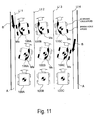
- Figure 11 is a diagram used for describing the braking control method in the third case
- Figure 12 is a flowchart showing the processing content of a driving/braking force control unit as a component of the lane departure prevention apparatus in accordance with a second embodiment of the present invention.
- Figure 13 is a flowchart showing the processing content of the apparatus operation detection during the processing of the driving/braking force control unit in accordance with the second embodiment of the present invention.
- FIG. 1 a schematic structural diagram of a host vehicle is illustrated that is equipped with a lane departure prevention apparatus in accordance with a first embodiment of the present invention.
- the embodiment is a rear wheel drive vehicle equipped with the lane departure prevention apparatus of the present invention.
- This rear-wheel-drive vehicle is equipped with an automatic transmission and a conventional differential gear, and with a braking system that allows independent control of braking force at the front and rear wheels and the left and right wheels.
- the host vehicle is basically equipped with a brake pedal 1, a booster 2, a master cylinder 3, a reservoir 4, a pair of front wheels 5FL and 5FR, a pair of rear wheels 5RL and 5RR, a pair of front wheel cylinders 6FL and 6FR, a pair of rear wheel cylinders 6RL and 6RR, a brake hydraulic pressure control unit 7, a driving/braking force control unit 8, an internal combustion engine 9, an automatic transmission 10, a throttle valve 11, a drive torque control unit 12, an imaging unit 13, a navigation device 15, a master cylinder pressure sensor 17, a throttle aperture sensor 18, a steering angle sensor 19, a turn signal switch 20, a steering wheel 21, a pair of front wheel velocity sensors 22FL to 22FR and a pair of rear wheel velocity sensors 22RL to 22RR.
- a brake pedal 1 a booster 2
- a master cylinder 3 a reservoir 4
- a pair of front wheels 5FL and 5FR a pair of rear wheels 5RL and 5RR
- a pair of front wheel cylinders 6FL and 6FR a pair of rear
- the wheel cylinders 6FL to 6RR, the brake hydraulic pressure control unit 7, the driving/braking force control unit 8 all form part of a braking apparatus that allows independent control of braking force for the front and rear wheels and the left and right wheels.
- the brake hydraulic pressure is boosted by the master cylinder 3 such that the brake fluid is ordinarily fed to the wheel cylinders 6FL to 6RR of the wheels 5FL to 5RR in accordance with the downward force (depression amount) exerted by the driver on the brake pedal 1.
- the brake hydraulic pressure control unit 7 is interposed between the master cylinder 3 and the wheel cylinders 6FL to 6RR for allowing the brake hydraulic pressure of the wheel cylinders 6FL to 6RR to be individually controlled by the brake hydraulic pressure control unit 7.
- the controller 8 preferably includes a microcomputer with a lane departure prevention control program that controls the wheel cylinders 6FL, 6FR, 6RL and 6RR to apply a yaw moment to the host vehicle as discussed below.
- the controller 8 can also include other conventional components such as an input interface circuit, an output interface circuit, and storage devices such as a ROM (Read Only Memory) device and a RAM (Random Access Memory) device.
- the memory circuit stores processing results and control programs such as ones for controlling the braking control operations that are run by the processor circuit.
- the controller 8 is operatively coupled to the above mentioned sensors in a conventional manner.
- the internal RAM of the controller 8 stores statuses of operational flags and various control data.
- the internal ROM of the controller 8 stores the programs and predetermined variables for various operations.
- the controller 8 is capable of selectively controlling any number of the components of the host vehicle as needed and/or desired. It will be apparent to those skilled in the art from this disclosure that the precise structure and algorithms for the controller 8 can be any combination of hardware and software that will carry out the functions of the present invention. In other words, "means plus function" clauses as utilized in the specification and claims should include any structure or hardware and/or algorithm or software that can be utilized to carry out the function of the "means plus function” clause.
- the brake hydraulic pressure control unit 7 is preferably configured and arranged, for example, to carry out anti-skid control and traction control.
- the brake hydraulic pressure control unit 7 is also configured and arranged to independently control the braking hydraulic pressure of the wheel cylinders 6FL to 6RR.
- the brake hydraulic pressure control unit 7 is also configured so as to control the brake hydraulic pressure in accordance with a brake hydraulic pressure command value when the brake hydraulic pressure command value is input from the driving/braking force control unit 8 (described below).
- the drive torque control unit 12 controls the drive torque to the rear wheels 5RL and 5RR, which are the drive wheels, by controlling the operating conditions of the engine 9, the selected gear ratio of the automatic transmission 10, and/or the throttle opening of a throttle valve 11.
- the drive torque control unit 12 controls the fuel injection amount and the ignition timing, and controls the operating condition of the engine 9 by simultaneously controlling the size of the throttle aperture. With this drive torque control unit 12, the value of the drive torque Tw that is used for control is output to the driving/braking force control unit 8.
- the drive torque control unit 12 is also configured to independently control the drive torque of the rear wheels 5RL and 5RR.
- the drive torque control unit 12 is also configured to control the drive wheel torque in accordance with a drive torque command value when the drive torque command value is input from the driving/braking force control unit 8.
- the imaging unit 13 has a picture processing function.
- the imaging unit 13 is designed to detect the position of the host vehicle in the driving lane in order to detect the lane departure tendency of the host vehicle.
- the imaging unit 13 is configured to pick up an image with a monocular (single-lens) camera composed of a CCD (Charge Coupled Device) camera, for example.
- the imaging unit 13 is preferably disposed on the front of the host vehicle.
- the imaging unit 13 is preferably configured and arranged to detect white lines or other lane markers, for example, from the imaging picture of the area in front of the host vehicle. Thus, the driving lane is detected based on the detected lane markers. Furthermore, the imaging unit 13 calculates the angle (yaw angle) ⁇ formed by the driving lane of the host vehicle and the longitudinal axis of the host vehicle, the lateral displacement X from the center of the driving lane, the driving lane curvature ⁇ , and the like based on the detected driving lane. The imaging unit 13 outputs the calculated yaw angle ⁇ , the calculated lateral displacement X, the calculated driving lane curvature ⁇ , and the like to the driving/braking force control unit 8.
- the navigation device 15 is preferably configured and arranged to detect the yaw rate ⁇ ' and the lateral acceleration Xg and/or the longitudinal acceleration Yg generated in the host vehicle.
- the navigation device 15 outputs the detected lateral acceleration Xg, the detected longitudinal acceleration Yg, and the detected yaw rate ⁇ ' to the driving/braking force control unit 8.
- the navigation device 15 also outputs road information to the driving/braking force control unit 8.
- the road information i.e., host vehicle driving environment
- the road information includes information about the type of the road, such as the number of lanes and whether the road is an ordinary road or an expressway.
- the master cylinder pressure sensor 17 is preferably configured and arranged to detect the output pressure of the master cylinder 3, that is, the master cylinder hydraulic pressures Pmf and Pmr.
- the accelerator depression or throttle aperture opening sensor 18 is preferably configured and arranged to detect the downward force on the accelerator pedal 1 or the throttle aperture opening size to output a signal indicative of the aperture size Acc.
- the steering angle sensor 19 is preferably configured and arranged to detect the steering angle ⁇ of the steering wheel 21.
- the turn signal switch 20 is preferably configured and arranged to detect turn signal operation with a turn signal indicator.
- the hazard switch 31 is provided for switching between hazard lighting and non-lighting in accordance with the intention of the driver. All of these detection signals detected by these sensors or the like are output to the driving/braking force control unit 8.
- the two directions are set such that the left direction is the positive direction.
- the yaw rate ⁇ ', the longitudinal acceleration Yg, and the yaw angle ⁇ are positive values when turning left
- the lateral displacement X is a positive value when shifting from the center of the driving lane to the left.
- the driving/braking force control unit 8 is configured so as to control the components constituting the vehicle.
- the driving/braking force control unit 8 is configured so as to control each of the components on the basis of signals or the like input from sensors and other components as described above.
- control by the driving/braking force control unit 8 includes control for preventing the vehicle from departing from the driving lane when the vehicle is tending toward departure from the driving lane.
- the system for avoiding departure is composed of the driving/braking force control unit 8.
- a system-operating switch 32 is provided to the vehicle for switching such a system ON and OFF. The driver can thereby enable such a lane departure-avoiding system to operate by turning the system-operating switch 32 to the ON position, and can disable the lane departure-avoiding system by turning the system-operating switch 32 to the OFF position.
- the lane departure prevention apparatus of the present invention sets the braking control for avoiding departure in an operable state when the braking control for avoiding the lane departure with the lane departure avoidance activation section or device is in a non-operating state, and the driver condition detection section or device detects that the condition of the driver is a condition in which the driver cannot perceive that the host vehicle is tending toward departure.
- the lane departure prevention apparatus of the present invention is thereby configured such that the braking control for avoiding host vehicle departure operates when the host vehicle is tending toward departure even when the braking control for avoiding the lane departure with the lane departure avoidance activation section or device is in a non-operating state, and the driver condition detection section or device detects that the condition of the driver is a condition in which the driver cannot perceive that the host vehicle is tending toward departure.
- the lane departure prevention apparatus can prevent lane departure even in a state in which the braking control for avoiding the lane departure with the lane departure avoidance activation section or device is in a non-operating state, and the condition of the driver is a condition in which the driver cannot perceive that the host vehicle is tending toward departure.
- Air conditioning equipment 33 and audio equipment 34 are also provided to the vehicle.
- the driver can operate the air conditioning equipment 33 to adjust the temperature inside the car, and operate the audio equipment 34 to play music inside the car.
- a warning sound output unit 35 is also provided to the vehicle.
- the warning sound output unit 35 is configured to be driven by a drive signal from driving/braking force control unit 8.
- the drive timing and other facets of the warning sound output unit 35 are described in detail later.
- This computational processing is executed by using a timer interrupt at each specific predetermined sampling time interval ⁇ T, such as every 10 msec for example.
- Communication processing is not included in the processing shown in Figure 2, but the information obtained by computational processing is updated and stored in random access memory, and required information is read out from the random access memory when required.
- step S1 various kinds of data are read from the above-described sensors, by the driving/braking force control unit 8. More specifically, the following types of data are read: the lateral acceleration Xg, the longitudinal acceleration Yg, the yaw rate ⁇ ', and the road information obtained by the navigation device 15; the wheel velocity Vwi; the steering angle ⁇ , the accelerator depression amount or throttle opening aperture size Acc; the master cylinder hydraulic pressures Pmf and Pmr; the turn switch signal WS from the turn signal switch 20; the signal for the hazard switch 31; the drive torque Tw from the drive torque control unit 12; and the yaw angle ⁇ , the lateral displacement X, and the driving lane curvature ⁇ from the imaging unit 13.
- the following types of data are read: the lateral acceleration Xg, the longitudinal acceleration Yg, the yaw rate ⁇ ', and the road information obtained by the navigation device 15; the wheel velocity Vwi; the steering angle ⁇ , the accelerator depression amount or throttle opening aperture size Acc; the master
- step S2 a determination is made as to whether the system-operating switch 32 is ON.
- the system advances to step S5, and when the system-operating switch 32 is OFF, the system advances to step S3.
- step S3 a determination is made as to whether the hazard switch 31 has been ON for a predetermined period of time T H . The determination is made based on a signal from the hazard switch 31, for example.
- the system advances to step S4, and when the hazard switch 31 has not been ON for a predetermined period of time T H , processing is performed again from step S1.
- step S4 the system-operating switch 32 is forcibly switched ON. The system then advances to step S5.
- step S5 the host vehicle velocity V is calculated based on the average value of the wheel velocities of the non-driven wheels.
- the host vehicle is driven by the rear wheels, so the host vehicle velocity V is calculated based on the velocities Vw FL and Vw FR of the front left and right wheels 5FL and 5FR.
- the host vehicle velocity V is calculated using one of the Equations (1) as shown below, based on the wheel velocity Vwi of the non-driven wheels that was read in the above-described step S 1.
- V (Vwrl + Vwrr)/2 for front wheel drive
- V (Vwfl + Vwfr)/2 for rear wheel drive
- the terms Vwfl and Vwfr are the respective wheel velocities of the left and right front wheels, and the terms Vwrl and Vwrr are the respective wheel velocities of the left and right rear wheels.
- the host vehicle velocity V is calculated as the average value of the wheel speed of the driven wheels.
- the host vehicle is driven by the rear wheels, so the host vehicle velocity is calculated from the latter equation, i.e., based on the wheel velocity of the front wheels 5FL and 5FR.
- the host vehicle velocity V calculated in this manner is preferably used during normal driving.
- the ABS (Anti-lock Brake System) control or the like when the ABS (Anti-lock Brake System) control or the like is operating, for example, the estimated car body velocity that is estimated in the ABS control is used as the above-described vehicle velocity V.
- the value being used for the navigation information in the navigation device 15 can also be used as the above-described vehicle velocity V.
- the host vehicle driving environment is determined in the following step S6. More specifically, the type of road on which the host vehicle is traveling and the driving lane of the host vehicle are detected as the driving environment. The direction based on the level of safety is then determined from the detected results. The determination is made based on the video information from the imaging unit 13 and on the road information from the navigation device 15. In other words, the determination of the driving environment is made based on the number of lanes and the road-type information that indicates whether the road is an ordinary road or an expressway.
- Figure 3 shows the specific processing procedure for determining the driving environment.
- step S21 the type of road (ordinary road or expressway) currently being traveled is acquired from the road information provided by the navigation device 15. Furthermore, in step S22, the number of lanes of the road currently being traveled is acquired from the road information provided by the navigation device 15.
- the white line portion (lane-dividing line portion) is extracted from the imaging picture taken by the imaging unit 13.
- the road by being partitioned from the left-hand side by first to fourth white lines LI 1, LI 2, LI 3, and LI 4, is configured as a three-lane, one-way road, as shown in Figure 4.
- the imaging picture obtained for each lane is different.
- a picture composed of white lines extracted from the picture also differs in accordance with the driving lane.
- the imaging picture P taken by the imaging unit 13 of the host vehicle 100A is a unique picture mainly comprising first, second, and third white lines LI1, LI2, and LI 3, as shown in picture (A) of Figure 5.
- the imaging picture P taken by the imaging unit 13 of the host vehicle 100B is a unique picture mainly comprising first, second, third, and fourth white lines LI1, LI2, LI3, and LI4, as shown in picture (B) of Figure 5.
- the imaging picture P taken by the imaging unit 13 of the host vehicle 100C is a unique picture mainly comprising second, third, and fourth white lines LI 2, LI 3, and LI 4, as shown in picture (C) of Figure 5.
- the configuration of the white lines in the picture differs in accordance with the driving lane.
- the host vehicle driving lane is determined in the subsequent step S24. More specifically, the host vehicle driving lane is determined based on the information obtained in steps S22 and S23. In other words, the host vehicle driving lane is determined based on the number of lanes in the road currently being traveled by the host vehicle and the imaging picture (picture with the white lines extracted) taken by the imaging unit 13. For example, the picture obtained in accordance with the number of lanes and the driving lane is stored in advance as picture data, the picture data prepared in advance is compared with the number of lanes in the road currently being traveled by the host vehicle and the current imaging picture (picture with the white lines extracted) taken by the imaging unit 13, and the host vehicle driving lane is determined.
- the level of safety is the same in both the left and right directions with respect to the current driving lane because the host vehicle 100B would still be on the road were departure to occur in either direction.
- the level of safety is lower when the host vehicle departs in the right-hand direction, to the opposing lane than when the host vehicle departs in the left-hand direction to the neighboring lane.
- the imaging picture when the host vehicle is traveling on the two-lane, two-way road is one such as that shown in the picture (A) of Figure 5 for countries that drive on the left side of the road and such as that shown in the picture (C) of Figure 5 for countries that drive on the right side of the road.
- the imaging picture when the host vehicle is traveling on a two-lane, two-way road is the same imaging picture taken by the imaging unit 13 of the host vehicle 100A traveling in the left-hand lane of a three-lane road for countries that drive on the left side of the road.
- the obstacle-containing direction S out cannot be determined solely by using an imaging picture.
- the number of lanes in the road on which the host vehicle is currently traveling is obtained from the navigation device 15, and by making a determination as to whether the road currently being traveled is two-lane, two-way road or a three-lane, one-way road, it can be determined that the level of safety is low in the right-hand direction as well when a two-lane, two-way road is being traveled.
- step S6 shown in Figure 2 The evaluation of the driving environment in step S6 shown in Figure 2 is performed with the processing procedure shown in Figure 3 described above.
- Determination of the lane departure tendency is performed in the subsequent step S7.
- the processing procedure for processing this determination is specifically shown in Figure 6.
- the lane width L is obtained from the imaging picture processed by the imaging unit 13.
- the position of the host vehicle can also be obtained from the navigation device 15, and the lane width L can be obtained from the map data stored in the navigation device 15.
- the first departure-determining threshold Ts is variable.
- the first departure-determining threshold Ts can also be set, for example, based on the level of safety obtained in step S6.
- the lane departure tendency is determined in step S7 as described above.
- the intention of the driver to change lanes is determined in the subsequent step 58. More specifically, the intention of the driver to change lanes is determined as follows based on the steering angle ⁇ and/or the turn switch signal obtained in step S1.
- the driver intention to change lanes is determined based on the steering angle ⁇ .
- the control method for departure avoidance is selected in the subsequent step S9. More specifically, a determination is made as to whether or not to issue a lane departure alarm and/or to perform departure-avoiding braking control.
- the braking control method is selected when the lane departure-avoiding braking control is performed.
- a warning is sounded from the warning sound output unit 35, for example, in accordance with the ON and OFF state of the lane departure determination flag F out obtained in step S8.
- the lane departure determination flag F out is ON (T out ⁇ Ts), and a warning is sounded from the warning sound output unit 35 when it can be determined that lane departure can be prevented by the driver performing a steering operation or the like.
- those situations include ones in which the driver himself realizes the lane departure tendency of the host vehicle, and then takes evasive actions, but the lane departure determination flag F out itself is still ON (T out ⁇ Ts).
- the braking control method is also selected based on the obstacle-containing direction S out obtained in step S6 and the lane departure direction D out obtained in step S7. The procedure is described in detail hereinafter.
- the target yaw moment generated in the host vehicle is calculated in the subsequent step S10.
- Equation (3) the terms K1 and K2 are the gains that vary or fluctuate in accordance with the host vehicle velocity V.
- the gains K1 and K2 have lower values at low speeds, increase in a corresponding relationship with the host vehicle velocity V when the host vehicle velocity V reaches a certain value, and remain constant thereafter when a certain vehicle velocity V is reached.
- the lane departure-avoiding deceleration is calculated in the subsequent step S11.
- the braking force applied to both the left and right wheels is calculated with the aim of decelerating the host vehicle.
- such a braking force is calculated as target brake hydraulic pressures Pgf and Pgr applied to both the left and right wheels.
- the target brake hydraulic pressure Pgf for the front wheels is calculated with Equation (4) below.
- Pgf Kgv ⁇ V + Kgx ⁇ dx
- Equation (4) the terms Kgv and Kgx are conversion factors for converting the braking force into brake hydraulic pressure.
- the conversion factors Kgv and Kgx are respectively set based on the host vehicle velocity V and the amount of variation dx.
- the conversion factors Kgv and Kgx have higher values at low speeds, decrease in a corresponding relationship with the host vehicle velocity V when the host vehicle velocity V reaches a certain value, and remain constant thereafter when a certain vehicle velocity V is reached.
- the target brake hydraulic pressure Pgr is calculated for the rear wheels based on the target brake hydraulic pressure Pgf for the front wheels while taking the front and rear braking distribution into consideration.
- the deceleration (more specifically, the target brake hydraulic pressure Pgf and Pgr) for departure avoidance is obtained in this manner in step S11.
- the target brake hydraulic pressure for each wheel is calculated in the subsequent step S12.
- the final brake hydraulic pressure is calculated based on the presence of departure-avoiding braking control. More specifically, the calculation is performed in the following manner.
- Equations (5) and (6) the term Pmf is the master cylinder hydraulic pressure for the front wheels, while the term Pmr is the master cylinder hydraulic pressure for the rear wheels.
- the rear wheel master cylinder hydraulic pressure Pmr is a value calculated based on the master cylinder hydraulic pressure Pmf for the front wheels while taking the front and rear braking distribution into consideration.
- the front wheel target brake hydraulic pressure difference ⁇ Psf and the rear wheel target brake hydraulic pressure difference ⁇ Psr are first calculated based on the target yaw moment Ms. More specifically, the target brake hydraulic pressure differences ⁇ Psf and ⁇ Psr are calculated with Equations (7) to (10) below.
- Equations (7) to (10) the term Ms 1 is the threshold used for setting purposes, while the term T is the tread.
- the tread T is the same value for simplicity.
- Kbf, and Kbr are conversion factors for the front and rear wheels when the braking force is converted to brake hydraulic pressure, and are set according to brake parameters or specifications.
- the braking force applied to the wheels is thus distributed in accordance with the magnitude of the target yaw moment Ms. That is to say, when the target yaw moment Ms is less than the threshold Ms1 used for setting purposes, the front wheel target brake hydraulic pressure difference ⁇ Psf is set to 0, a predetermined value is assigned to the rear wheel target brake hydraulic pressure difference ⁇ Psr, and the braking force difference is generated in the left and right rear wheels.
- a predetermined value is assigned to the target brake hydraulic force differences ⁇ Psf and ⁇ Psr, and the braking force difference is generated in the front and rear left and right wheels.
- step S9 The braking control method selected in step S9 will now be described.
- step S9 when the lane departure determination flag F out is ON, the braking control method is selected based on the obstacle-containing direction S out and the lane departure direction D out .
- the braking control method selected based on the obstacle-containing direction S out and the lane departure direction D out when the lane departure determination flag F out is ON will be described below for various relationships between the obstacle-containing direction S out and the lane departure direction D out (first case to third case).
- the braking control (hereinafter referred to as "departure-avoiding yaw control") is carried out so that a yaw moment is imparted to the host vehicle for avoiding departure until the lane departure determination flag F out is OFF.
- the magnitude of the yaw moment imparted to the host vehicle in order to avoid departure is the target yaw moment Ms.
- the yaw moment is imparted to the host vehicle by creating a difference in the braking force applied to the left and right wheels. More specifically, when the target yaw moment Ms is less than the threshold Ms1 used for setting purposes, a braking force difference is generated in the left and right rear wheels to impart the target yaw moment Ms to the host vehicle. When the target yaw moment Ms is equal to or greater than the threshold Ms1 used for setting purposes, a braking force difference is generated in the front and rear left and right wheels to impart the target yaw moment Ms to the host vehicle, as described above.
- the lane departure determination flag F out is switched from ON to OFF in cases in which departure-avoiding braking control has been carried out or the driver himself has taken evasive actions when there is a lane departure tendency.
- the lane departure-avoiding yaw control is carried out until the lane departure determination flag F out is OFF.
- the second departure-determining threshold Tr which is less than the first departure-determining threshold Ts (Ts > Tr > 0), is defined.
- the lane departure-avoiding yaw control is applied, and the braking control for decelerating the host vehicle (hereinafter referred to as "departure-avoiding deceleration control") is carried out.
- the lane departure-avoiding deceleration control is carried out so as to provide substantially equal braking force to both the left and right wheels.
- the estimated time of departure T out is an indicator of the magnitude of the lane departure tendency, so an estimated time of departure that is less than the second departure-determining threshold Tr corresponds to the lane departure tendency being greater than the second threshold.
- the lane departure-avoiding yaw control is carried out until the lane departure determination flag F out is OFF.
- the lane departure-avoiding deceleration control can also be carried out when the estimated time of departure T out has become less than the second departure-determining threshold Tr, in the same manner as in the second case.
- the lane departure-avoiding deceleration control is configured so as to be actuated when the estimated time of departure T out has become less than the second departure-determining threshold Tr, and when the estimated time of departure T out becomes 0.
- the deceleration of the host vehicle is further increased.
- the braking control methods are selected in step S9 in accordance with the obstacle-containing direction S out and the lane departure direction D out in this manner.
- the braking control method for departure avoidance is selected by departure-avoiding yaw control alone or by a combination of the lane departure-avoiding yaw control and the lane departure-avoiding deceleration control in accordance with the obstacle-containing direction S out and the lane departure direction D out , and/or in accordance with the host vehicle velocity V and the estimated time of departure T out .
- Psfl Pmf + Pgf/2
- Psfr Pmf + ⁇ Psf + Pgf/2
- Psrl Pmr + Pgr/2
- Psrr Pmr + ⁇ Psr +Pgr/2
- the master cylinder hydraulic pressures Pmf and Pmr are applied, as shown in Equations (11) and (12).
- the lane departure prevention apparatus described above operates according to the following overview.
- step S1 various kinds of data are read from the sensors, the controllers, and the control units (step S1).
- the operating states of the system-operating switch 32 and hazard switch 31 are determined (steps S2 and S3).
- the system-operating switch 32 is ON, or when the system-operating switch 32 is OFF but the hazard switch 31 has been ON for predetermined length of time T H , the system advances to processing in a later step (processing in step S5 and thereafter); and when the system-operating switch 32 is OFF and the hazard switch 31 has not been ON for a predetermined length of time T H , processing is carried out again from the beginning (processing in step S1).
- step S4 When the system-operating switch 32 is OFF but the hazard switch 31 has been ON for a predetermined length of time T H , the system-operating switch 31 is forcibly switched ON when advancing to processing in a later step (step S4).
- step S5 the vehicle velocity V is calculated (step S5) in the first processing thereafter.
- step S6 the driving environment is determined and the direction (obstacle-containing direction S out ) in which the safety level is low is selected (see Figure 3).
- the direction (obstacle-containing direction S out ) in which the safety level is low is selected (see Figure 3).
- the obstacle-containing direction S out is set as the left-hand direction.
- step S7 the lane departure determination flag F out is set based on the estimated time of departure T out , and the lane departure direction D out is determined based on the lateral displacement X (see Figure 6).
- the driver's intention to change lanes is determined based on the lane departure direction D out obtained in this manner and on the direction (lighted blinker side) indicated by the turn switch signal (step S8).
- the lane departure determination flag F out is changed to OFF.
- the lane departure determination flag F out is kept unchanged in the case that it is ON.
- the direction (lighted blinker side) indicated by the turn switch signal and the direction indicated by the lane departure direction D out are different, the lane departure behavior of the host vehicle may be due to factors other than the driver's intention to change lanes or the like, so the condition of the lane departure determination flag F out is kept unchanged when the flag is ON.
- the start of an alarm for departure avoidance, the presence or absence of the lane departure-avoiding braking control, and the method for carrying out departure-avoiding braking control are selected based on the lane departure determination flag F out , the obstacle-containing direction S out , and the lane departure direction D out (step S9).
- the target yaw moment Ms is calculated based on the lateral displacement X and the variation amount dx (step S10), and departure-avoiding deceleration is also calculated (step S11).
- the brake hydraulic pressure is individually controlled for the wheel cylinders 6FL to 6RR based on the brake hydraulic pressure command value. Therefore, the configuration is such that when there is a lane departure tendency, a predetermined vehicle behavior is exhibited in accordance with the driving environment.
- the wheels colored in black in Figures 10 and 11 are those in which hydraulic pressure is generated and braking force is provided.
- hydraulic pressure is generated and braking force is provided.
- the left and right wheels when either one of the left and right wheels is a wheel colored in black, there is a difference in hydraulic pressure or braking force in the left and right wheels. This case shows a yaw moment imparted to the host vehicle.
- the left and right wheels are colored in black, there can still be a difference in the hydraulic pressure values thereof, in which case the host vehicle undergoes controlled deceleration while a yaw moment is simultaneously imparted to the host vehicle.
- the second case is one in which there is a match between the obstacle-containing direction S out and the lane departure direction D out , and where the road type R is an ordinary road.
- the road type R is an ordinary road.
- the host vehicle 100 when the host vehicle 100 is traveling on a two-lane, two-way road wherein the road shoulder A is to the left and the opposing lane (center lane LI 5 side) is to the right, there are cases in which the host vehicle 100 (the host vehicle 100 in the uppermost position of Figure 10) may tend to depart in the left-hand direction, and cases in which the host vehicle (the host vehicle 100 in the center position of Figure 10) may tend to depart in the right-hand direction, as shown in Figure 10.
- the lane departure-avoiding yaw control is carried out. Furthermore, when the estimated time of departure T out becomes less than the second departure-determining threshold Tr, the lane departure-avoiding yaw control is applied, and the lane departure-avoiding deceleration control is carried out.
- the host vehicle thereby avoids departure. The driver can feel the lane departure avoidance action as acceleration in the lateral direction or as deceleration in the direction of travel, and know that the host vehicle has a tendency to depart.
- the third case is one in which there is a match between the first obstacle-containing direction S out and the lane departure direction D out , and where the road type R is an expressway.
- this is a case in which the host vehicle 100A (host vehicle 100A in the uppermost position of Figure 11) traveling in the left-hand lane on a three-lane, one-way road has a tendency to depart in the left-hand direction, as shown in Figure 11.
- An alternative case is one in which the host vehicle 100C (host vehicle 100C in the center position of Figure 11) traveling in the right-hand lane on a three-lane, one-way road has a tendency to depart in the right-hand direction, as shown in Figure 11.
- departure-avoiding yaw control is carried out.
- the host vehicle can thereby avoid departure.
- the estimated time of departure T out reaches 0, in other words, when it is determined that the host vehicle has departed from the driving lane, the lane departure-avoiding yaw control is applied, and the lane departure-avoiding deceleration control is carried out.
- the first case is one in which there is no match between the obstacle-containing direction S out and the lane departure direction D out .
- the host vehicle 100A host vehicle 100A in the center position of Figure 11
- one-way road has a tendency to depart in the right-hand direction, as shown in Figure 11.
- the host vehicle 100C host vehicle 100C in the lowermost position of Figure 11
- the host vehicle 100B traveling in the center lane has a tendency to depart in the left-hand or right-hand direction.
- the lane departure-avoiding yaw control is carried out in this case. The host vehicle can thereby avoid departure.
- Braking control for this type of departure avoidance is performed and an alarm is issued with a sound or display.
- the alarm is initiated with a predetermined timing in advance of braking control, or simultaneously with braking control, for example.
- the system-operating switch 32 When, as described above, the system-operating switch 32 is OFF but the hazard switch 31 has been ON for a predetermined length of time T H , the system advances to processing in a later step (processing in step S5 and thereafter).
- the system for departure avoidance is automatically set in an operable state or in an operating standby state, so when the host vehicle is about to depart, control for departure avoidance is performed based on the details of braking control described above.
- the system for departure avoidance is thus set in an operable state and the time (hereinafter referred to as "operating time") T F_H during which the system is in the operable state is kept constant. More specifically, the operating time T F_H is set in accordance with the time that the hazard switch 31 is being operated.
- a warning is sounded with the warning sound output unit 35, and braking control such as departure-avoiding yaw control or departure-avoiding deceleration control is thereafter performed when the host vehicle is tending toward departure from the driving lane.
- the output timing of such a warning output is set earlier than in ordinary circumstances. More specifically, in the lane departure prevention apparatus, the warning output is carried out with predetermined timing when the host vehicle is tending toward departure, but the predetermined timing is advanced to an earlier timing than is used in ordinary circumstances.
- a warning begins to sound from the warning sound output unit 35 with earlier timing than in ordinary circumstances when the host vehicle is tending toward departing from the driving lane in the case that the system for departure avoidance is set in an operable state, and braking control such as departure-avoiding yaw control or departure-avoiding deceleration control operates thereafter with a certain timing.
- the system for departure avoidance is automatically set in an operable state even when the system-operating switch 32 has been switched OFF by the driver. Control for departure avoidance is performed based on the braking control details in accordance therewith when the host vehicle is tending toward departure.
- the lane departure can be avoided by automatically setting the system for departure avoidance in an operable state, even when the condition of the driver is a condition in which the driver cannot perceive that the host vehicle is tending toward departure.
- the hazard switch 31 has been ON for a predetermined length of time T H is a case in which the driver is in a condition wherein he cannot perceive that the host vehicle is tending toward departure
- the lane departure can be avoided by automatically setting the system for departure avoidance in an operable state.
- the operating time T F_H of the system when the system for departure avoidance has automatically been set in an operable state is set in accordance with the time the hazard switch 31 has been operated.
- the operating time of the system for departure avoidance can thereby be suitably set.
- a case in which the driver may switch OFF the system-operating switch 32 is one in which the driver may feel annoyance at control for departure avoidance when departure-avoiding action can be performed by the driver himself.
- the operating time T F_H is preferably divided into set time periods, even when the system for departure avoidance is set in an operable state because the driver is in a condition in which he cannot perceive that the host vehicle is tending toward departure. Therefore, the system for departure avoidance can be suitably set in an operable state by setting the operating time T F_H in accordance with the length of time the hazard switch 31 has been operated.
- a warning is sounded with the warning sound output unit 35, and braking control such as departure-avoiding yaw control and departure-avoiding deceleration control is thereafter performed when the host vehicle is tending toward departure from the driving lane.
- braking control such as departure-avoiding yaw control and departure-avoiding deceleration control is thereafter performed when the host vehicle is tending toward departure from the driving lane.
- the output timing of such a warning sound is carried out earlier than in ordinary circumstances.
- the driver who is in a state in which he cannot perceive that the host vehicle is tending toward departure can be informed at an early stage that the host vehicle is tending toward departure.
- Figure 12 shows the processing content of a driving/braking force control unit as a component of the lane departure prevention apparatus of Figure 1 in accordance with a second embodiment of the present invention.
- Figure 13 shows the processing content of the apparatus operation detection during the processing of the driving/braking force control unit in accordance with the second embodiment of the present invention.
- the parts and/or processing used in the second embodiment that are identical to the parts and/or processing of the first embodiment will be given the same reference numerals as the parts and/or processing of the first embodiment.
- the descriptions of the parts of the second embodiment that are identical to the parts and/or processing of the first embodiment may be omitted for the sake of brevity.
- the system for departure avoidance is automatically set in an operable state on the basis of the ON operation of the hazard switch 31, but in the second embodiment the operating state of other devices and the like is also taken into consideration to automatically set the system for departure avoidance in an operable state. More specifically, the operating state of the navigation device 15, the air conditioning equipment 33, and the audio equipment 34 provided to the vehicle as shown in Figure 1 are taken into consideration, and the system for departure control is automatically set in an operable state.
- the driving/braking force control unit 8 performs processing for avoiding departure with consideration for the state of any of these devices being operated by the driver.
- Switches for detecting the operating state of the devices are provided, for example, and the driving/braking force control unit 8 detects the operating state of the devices on the basis of the states of the switches.
- Figures 12 and 13 show the specific processing procedures.
- the processing procedures are substantially the same as the processing procedures ( Figure 2) of the first embodiment.
- step S1 shown in Figure 12 various data is read in step S1 shown in Figure 12.
- the driving/braking force control unit 8 reads the state (operating signal) of the navigation device 15, the air conditioning equipment 33, and the audio equipment 34 being operated by the driver.
- the operating states of these devices are read based on the state of the switches, as described above.
- step S2 a determination is made as to whether the system-operating switch 32 is ON. If the system-operating switch 32 is ON, the system advances to step S5, and if the system-operating switch 32 is OFF, the system advances to step S40.
- step S40 in addition to the operating state of the hazard switch 31, the operating states of the navigation device 15, the air conditioning equipment 33, and the audio equipment 34 are also detected.
- Figure 13 shows the detection processing procedure.
- step S41 a determination is made as to whether the hazard switch 31 has been ON for predetermined length of time T H . In this case, if the hazard switch 31 has been ON for predetermined length of time T H , the system advances to step S4 shown in Figure 12, and if the hazard switch 31 has not been ON for predetermined length of time T H , the system advances to step S42.
- step S42 a determination is made as to whether the air conditioning equipment 33 is being operated by the driver. In this case, if the driver is operating the air conditioning equipment 33, the system advances to step S4 shown in Figure 12, and if the driver is not operating the air conditioning equipment 33, the system advances to step S43.
- step S43 a determination is made as to whether the audio equipment 34 is being operated by the driver. In this case, if the driver is operating the audio equipment 34, the system advances to step S4 shown in Figure 12, and if the driver is not operating the audio equipment 34, the system advances to step S44.
- step S44 a determination is made as to whether the navigation device 15 is being operated by the driver. In this case, if the driver is operating the navigation device 15, the system advances to step S4 shown in Figure 12, and if the driver is not operating the navigation device 15, processing is performed again from step S1.
- step S4 shown in FIG. 12 the system-operating switch 32 is forcibly switched ON.
- the system then advances to step S5 in the same manner as in the first embodiment.
- the processing performed in the subsequent steps S5 to S12 include calculation of the vehicle velocity, determination of the driving environment, determination of the lane departure tendency, determination of the driver intention, selection of the braking method, calculation of the target yaw moment, calculation of the lane departure-avoiding deceleration, and calculation of the target brake hydraulic pressure for each wheel in the same manner as in the first embodiment.
- the system for departure avoidance is automatically set in an operable state by processing such as that described above when the hazard switch 31 has been operated for a length of time equivalent to a predetermined amount of time T H even when the system-operating switch 32 is OFF. Also, when the driver has been operating the air conditioning equipment 33 for a predetermined length of time T AC , the system for departure avoidance is automatically set in an operable state even if the system-operating switch 32 is OFF. Furthermore, when the driver has been operating the audio equipment 34 for a predetermined length of time T aud , the system for departure avoidance is automatically set in an operable state even if the system-operating switch 32 is OFF. Moreover, when the driver has been operating the navigation device 15 for a predetermined length of time T nav , the system for departure avoidance is automatically set in an operable state even if the system-operating switch 32 is OFF.
- control for departure avoidance operates based on the braking control details when the host vehicle is tending toward departure by automatically setting the system for departure avoidance in an operable state.
- the system for departure avoidance is automatically set in an operable state in this manner on the basis of the operating states of the switches and devices, and the operating times thereof are set to fixed lengths of time. More specifically, the operating times are set in accordance with the operated switches and devices.
- the operating time when the hazard switch 31 is ON is defined as T F_H
- the operating time when the air conditioning equipment 33 is operated is defined as T F_ac
- the operating time when the audio equipment 34 is operated is defined as T F_aud
- the operating time when the navigation device 15 is operated is defined as T F_nav
- T F_nav T F_nav
- the operating time is commonly greater in the following order: the operating time of the hazard switch 31 and the operating time of the air conditioning equipment 32, the operating time of the audio equipment 34, and the operating time of the navigation device 15. In other words, the operating time it extended with an increase in the time required for operation.
- the value of the time that the hazard switch 31 has been ON can be used unchanged as the operating time, or the value of the time that the devices have been operating can be used unchanged as the operating time. Alternately, the operating time may be set longer with respect to the ON time or the operating time.
- the system for departure avoidance can be suitably set in an operable state in accordance with the condition of the driver when the driver cannot perceive that the host vehicle is tending toward departure, by setting the operating time in correspondence with the respective operating times of the switches and devices.
- the present invention is not limited to being realized in the above-described embodiments.
- a detailed description was given in the above embodiments concerning the methods of combining braking control (departure-avoiding yaw control) so that a yaw moment for avoiding departure is imparted to the host vehicle, and deceleration control (departure-avoiding deceleration control) for decelerating to avoid departure; the operating order of these methods; and the control amounts used in these methods (magnitude of the yaw moment, and magnitude of the deceleration).
- the present invention is not limited thereby.
- the present invention may be applied as long as the object of application is a lane departure prevention apparatus that prevents the host vehicle from departing by brake control.
- the driver is in a condition in which he cannot perceive that the host vehicle is tending toward departure was described in the embodiments described above on the basis of the operating condition of the hazard switch 31 and various devices.
- the present invention is not limited thereby.
- the posture, actions, or the consciousness state of the driver in the car, or the field of vision of the driver may be detected, and, based on the detection results, it may be determined that the condition of the driver is a condition in which the driver cannot perceive that the host vehicle is tending toward departure.
- a warning is sounded from the warning sound output unit 35, and braking control such as departure-avoiding yaw control and departure-avoiding deceleration control are thereafter performed in the case that the system for departure avoidance is set in an operable state and the host vehicle is tending toward departure from the driving lane.
- the action may be limited to the sounding of a warning from the warning sound output unit 35 in the case that the system for departure avoidance is set in an operable state and the host vehicle is tending toward departure from the driving lane.
- the warning output may be a warning display or any other device that can draw the attention of the driver.
- the estimated time to departure T out was calculated (refer to Equation (2)) in the above-described embodiments based on the lateral displacement X and the variation dx thereof.
- the estimated time to departure T out can also be obtained by another method.
- the estimated time to departure T out may also be obtained based on the yaw angle ⁇ , yaw rate ⁇ ', or steering angle ⁇ .
- the intention of the driver to change lanes is obtained based on the steering angle ⁇ and the variation of the steering angle (refer to step S8).
- the intention of the driver to change lanes can also be obtained by another method.
- the intention of the driver to change lanes can be obtained based on the steering torque.
- the target yaw moment Ms was calculated (refer to Equation (3)) in the above-described embodiments based on lateral displacement X and the variation dx.
- the target yaw moment Ms can also be obtained by another method.
- the target yaw moment Ms can also be obtained based on the yaw angle ⁇ , lateral displacement X, and driving lane curvature ⁇ , as shown in Equation (17) below.
- Ms K3 ⁇ ⁇ + K4 ⁇ X + K5 ⁇ ⁇
- K3, K4, and K5 are gains that vary with velocity V.
- the target brake hydraulic pressure Pgf for the front wheels in the above embodiments was described with the aid of a specific equation (refer to Equation (4)).
- the present invention is not limited thereby.
- the target brake hydraulic pressure Pgf for the front wheels can also be calculated with Equation (14) below.
- Pgf Kgv ⁇ V + Kg ⁇ ⁇ ⁇ + Kg ⁇ ⁇ ⁇
- Kg ⁇ and Kg ⁇ are, respectively, conversion factors that are used for converting braking force to brake hydraulic pressure and are set based on the yaw angle ⁇ and driving lane curvature ⁇ .
- the target hydraulic pressure differences ⁇ Psf and ⁇ Psr for the front and rear wheels are calculated in order to realize departure-avoiding yaw control in the embodiments described above (refer to Equations (7) and (8)).
- the present invention is not limited thereby.
- the lane departure-avoiding yaw control can be realized solely with front wheel target hydraulic pressure difference ⁇ Psf.
- the front wheel target hydraulic pressure difference ⁇ Psf is calculated with Equation (15) below.
- ⁇ Psf 2 ⁇ Kbf ⁇ Ms/T
- the system-operating switch 32 is an embodiment of the lane departure avoidance activation section or device for the driver to instruct the operation of control braking for avoiding the lane departure.
- the processing routine of step S3 of the driving/braking force control unit 8 is an embodiment of the driver condition detection section or device for detecting that the condition of the driver is a condition in which the driver cannot perceive that the host vehicle is tending toward departure.
- the processing routine of steps S2 to S4 of the driving/braking force control unit 8 is an embodiment of the lane departure avoidance control device for setting the braking control for avoiding departure in an operable state when the braking control for avoiding the lane departure with the lane departure avoidance activation section or device is in a non-operating state, and the driver condition detection section or detects that the condition of the driver is a condition in which the driver cannot perceive that the host vehicle is tending toward departure.
- the following directional terms "forward, rearward, above, downward, vertical, horizontal, below, and transverse” as well as any other similar directional terms refer to those directions of a vehicle equipped with the present invention. Accordingly, these terms, as utilized to describe the present invention should be interpreted relative to a vehicle equipped with the present invention. Moreover, terms that are expressed as “means-plus function” in the claims should include any structure that can be utilized to carry out the function of that part of the present invention.
- the terms of degree such as “substantially”, “about”, and “approximately” as used herein mean a reasonable amount of deviation of the modified term such that the end result is not significantly changed. For example, these terms can be construed as including a deviation of at least ⁇ 5% of the modified term if this deviation would not negate the meaning of the word it modifies.
Abstract
Description
- The present invention generally relates to a lane departure prevention apparatus for preventing a host vehicle from departing from a driving lane when the host vehicle is about to depart from the lane or departure seems imminent.
- Conventional lane departure prevention apparatuses include apparatuses for imparting yaw moment to the host vehicle by controlling the braking force to the wheel and preventing the host vehicle from deviating from the driving lane. These conventional lane departure prevention apparatuses also inform the driver that the host vehicle may possibly depart from the driving lane by providing this yaw moment in cases in which there is a possibility that the host vehicle may depart from a driving lane. For example, one such lane departure prevention apparatus is disclosed in Japanese Laid-Open Patent Publication No. 2000-33860.
- The lane departure prevention apparatus is provided with an operating switch for switching the system ON and OFF. The driver can thereby select the operable state of the lane departure prevention apparatus by switching the operating-switch ON and OFF. When the driver thinks that the control for avoiding departure is not needed, the feelings of annoyance at unwanted intervention by control for departure avoidance can be eliminated by switching the operating-switch OFF.
- In view of the above, it will be apparent to those skilled in the art from this disclosure that there exists a need for an improved lane departure prevention apparatus. This invention addresses this need in the art as well as other needs, which will become apparent to those skilled in the art from this disclosure.
- It has been discovered that there are cases in which the attention of the driver is not focused on driving operations in a state in which the system-operating switch is OFF. For example, there are cases in which the driver has forgotten that the operating-switch is OFF and another onboard device such the hazard switch is operating. In this case, the driver is not aware that the operating-switch should be switched ON in spite of the fact that the host vehicle is tending toward departure, so the host vehicle will depart from the lane in its present state.
- The present invention was contrived in view of the above-described problems. One object of the present invention is to provide a lane departure prevention apparatus that can avoid lane departure even when the driver is not focused on driving operations, in a state in which the system-operating switch is OFF.
- In order to solve some of the above-described problems, the lane departure prevention apparatus of the present invention is provided with a lane departure avoidance activation section, a driver condition detection section, and a lane departure avoidance control section. The lane departure avoidance activation section is configured to be activated by a driver to conduct a braking control operation for avoiding lane departure of a host vehicle from a driving lane when the host vehicle is tending to depart from the driving lane. The driver condition detection section is configured to detect that a driver condition tending to indicate a driver may not perceive that the host vehicle is tending toward lane departure. The lane departure avoidance control section is configured to switch the braking control operation for avoiding lane departure from a non-operating state to an operable state, when the driver condition detection section detects that the driver condition is tending to indicate that the driver may not perceive that the host vehicle is tending toward lane departure.
- These and other objects, features, aspects and advantages of the present invention will become apparent to those skilled in the art from the following detailed description, which, taken in conjunction with the annexed drawings, discloses preferred embodiments of the present invention.
- Referring now to the attached drawings which form a part of this original disclosure:
- Figure 1 is a schematic structural diagram of a vehicle equipped with a lane departure prevention apparatus in accordance a first embodiment of the present invention;
- Figure 2 is a flowchart showing the processing content of a driving/braking force control unit as a component of the lane departure prevention apparatus;
- Figure 3 is a flowchart showing the processing content for determining the driving environment by the driving/braking force control unit;
- Figure 4 is a diagram showing vehicles traveling on a three-lane, one-way road;
- Figure 5 is a diagram showing an imaging picture taken by the host vehicle in each lane position when the host vehicle is traveling on a three-lane, one-way road;
- Figure 6 is a flowchart showing the processing content for determining the lane departure tendency by the driving/braking force control unit;
- Figure 7 is a diagram used for describing the estimated time of departure Tout;
- Figure 8 is a characteristics diagram showing the characteristics of gains K1 and K2 that are used for calculating the yaw moment Ms;
- Figure 9 is a characteristics diagram showing the characteristics of conversion factors Kgv and Kgx that are used for calculating the target brake hydraulic pressure Pgf;
- Figure 10 is a diagram used for describing the braking control method in the second case;
- Figure 11 is a diagram used for describing the braking control method in the third case;
- Figure 12 is a flowchart showing the processing content of a driving/braking force control unit as a component of the lane departure prevention apparatus in accordance with a second embodiment of the present invention; and
- Figure 13 is a flowchart showing the processing content of the apparatus operation detection during the processing of the driving/braking force control unit in accordance with the second embodiment of the present invention.
- Selected embodiments of the present invention will now be explained with reference to the drawings. It will be apparent to those skilled in the art from this disclosure that the following descriptions of the embodiments of the present invention are provided for illustration only and not for the purpose of limiting the invention as defined by the appended claims and their equivalents.
- Referring initially to Figure 1, a schematic structural diagram of a host vehicle is illustrated that is equipped with a lane departure prevention apparatus in accordance with a first embodiment of the present invention. The embodiment is a rear wheel drive vehicle equipped with the lane departure prevention apparatus of the present invention. This rear-wheel-drive vehicle is equipped with an automatic transmission and a conventional differential gear, and with a braking system that allows independent control of braking force at the front and rear wheels and the left and right wheels.
- In the diagram of Figure 1, the host vehicle is basically equipped with a
brake pedal 1, abooster 2, amaster cylinder 3, areservoir 4, a pair of front wheels 5FL and 5FR, a pair of rear wheels 5RL and 5RR, a pair of front wheel cylinders 6FL and 6FR, a pair of rear wheel cylinders 6RL and 6RR, a brake hydraulicpressure control unit 7, a driving/brakingforce control unit 8, aninternal combustion engine 9, anautomatic transmission 10, athrottle valve 11, a drivetorque control unit 12, animaging unit 13, anavigation device 15, a mastercylinder pressure sensor 17, athrottle aperture sensor 18, asteering angle sensor 19, aturn signal switch 20, asteering wheel 21, a pair of front wheel velocity sensors 22FL to 22FR and a pair of rear wheel velocity sensors 22RL to 22RR. - The wheel cylinders 6FL to 6RR, the brake hydraulic
pressure control unit 7, the driving/brakingforce control unit 8 all form part of a braking apparatus that allows independent control of braking force for the front and rear wheels and the left and right wheels. The brake hydraulic pressure is boosted by themaster cylinder 3 such that the brake fluid is ordinarily fed to the wheel cylinders 6FL to 6RR of the wheels 5FL to 5RR in accordance with the downward force (depression amount) exerted by the driver on thebrake pedal 1. Also, the brake hydraulicpressure control unit 7 is interposed between themaster cylinder 3 and the wheel cylinders 6FL to 6RR for allowing the brake hydraulic pressure of the wheel cylinders 6FL to 6RR to be individually controlled by the brake hydraulicpressure control unit 7. - The
controller 8 preferably includes a microcomputer with a lane departure prevention control program that controls the wheel cylinders 6FL, 6FR, 6RL and 6RR to apply a yaw moment to the host vehicle as discussed below. Thecontroller 8 can also include other conventional components such as an input interface circuit, an output interface circuit, and storage devices such as a ROM (Read Only Memory) device and a RAM (Random Access Memory) device. The memory circuit stores processing results and control programs such as ones for controlling the braking control operations that are run by the processor circuit. Thecontroller 8 is operatively coupled to the above mentioned sensors in a conventional manner. The internal RAM of thecontroller 8 stores statuses of operational flags and various control data. The internal ROM of thecontroller 8 stores the programs and predetermined variables for various operations. Thecontroller 8 is capable of selectively controlling any number of the components of the host vehicle as needed and/or desired. It will be apparent to those skilled in the art from this disclosure that the precise structure and algorithms for thecontroller 8 can be any combination of hardware and software that will carry out the functions of the present invention. In other words, "means plus function" clauses as utilized in the specification and claims should include any structure or hardware and/or algorithm or software that can be utilized to carry out the function of the "means plus function" clause. - The brake hydraulic
pressure control unit 7 is preferably configured and arranged, for example, to carry out anti-skid control and traction control. The brake hydraulicpressure control unit 7 is also configured and arranged to independently control the braking hydraulic pressure of the wheel cylinders 6FL to 6RR. Thus, the brake hydraulicpressure control unit 7 is also configured so as to control the brake hydraulic pressure in accordance with a brake hydraulic pressure command value when the brake hydraulic pressure command value is input from the driving/braking force control unit 8 (described below). - The drive
torque control unit 12 controls the drive torque to the rear wheels 5RL and 5RR, which are the drive wheels, by controlling the operating conditions of theengine 9, the selected gear ratio of theautomatic transmission 10, and/or the throttle opening of athrottle valve 11. The drivetorque control unit 12 controls the fuel injection amount and the ignition timing, and controls the operating condition of theengine 9 by simultaneously controlling the size of the throttle aperture. With this drivetorque control unit 12, the value of the drive torque Tw that is used for control is output to the driving/brakingforce control unit 8. - The drive
torque control unit 12 is also configured to independently control the drive torque of the rear wheels 5RL and 5RR. Thus, the drivetorque control unit 12 is also configured to control the drive wheel torque in accordance with a drive torque command value when the drive torque command value is input from the driving/brakingforce control unit 8. - The
imaging unit 13 has a picture processing function. Theimaging unit 13 is designed to detect the position of the host vehicle in the driving lane in order to detect the lane departure tendency of the host vehicle. Theimaging unit 13 is configured to pick up an image with a monocular (single-lens) camera composed of a CCD (Charge Coupled Device) camera, for example. Theimaging unit 13 is preferably disposed on the front of the host vehicle. - The
imaging unit 13 is preferably configured and arranged to detect white lines or other lane markers, for example, from the imaging picture of the area in front of the host vehicle. Thus, the driving lane is detected based on the detected lane markers. Furthermore, theimaging unit 13 calculates the angle (yaw angle) formed by the driving lane of the host vehicle and the longitudinal axis of the host vehicle, the lateral displacement X from the center of the driving lane, the driving lane curvature β, and the like based on the detected driving lane. Theimaging unit 13 outputs the calculated yaw angle , the calculated lateral displacement X, the calculated driving lane curvature β, and the like to the driving/brakingforce control unit 8. - The
navigation device 15 is preferably configured and arranged to detect the yaw rate ' and the lateral acceleration Xg and/or the longitudinal acceleration Yg generated in the host vehicle. Thenavigation device 15 outputs the detected lateral acceleration Xg, the detected longitudinal acceleration Yg, and the detected yaw rate ' to the driving/brakingforce control unit 8. Thenavigation device 15 also outputs road information to the driving/brakingforce control unit 8. Preferably, the road information (i.e., host vehicle driving environment) includes information about the type of the road, such as the number of lanes and whether the road is an ordinary road or an expressway. - The master
cylinder pressure sensor 17 is preferably configured and arranged to detect the output pressure of themaster cylinder 3, that is, the master cylinder hydraulic pressures Pmf and Pmr. The accelerator depression or throttleaperture opening sensor 18 is preferably configured and arranged to detect the downward force on theaccelerator pedal 1 or the throttle aperture opening size to output a signal indicative of the aperture size Acc. Thesteering angle sensor 19 is preferably configured and arranged to detect the steering angle δ of thesteering wheel 21. Theturn signal switch 20 is preferably configured and arranged to detect turn signal operation with a turn signal indicator. The wheel velocity sensors 22FL to 22RR are preferably configured and arranged to detect the rotational velocity of the wheels 5FL to 5RR, that is, the so-called wheel velocity Vwi (i = fl, fr, rl, rr). Here, thehazard switch 31 is provided for switching between hazard lighting and non-lighting in accordance with the intention of the driver. All of these detection signals detected by these sensors or the like are output to the driving/brakingforce control unit 8. - When there is left or right directionality in the detected driving condition or state data of the host vehicle, the two directions are set such that the left direction is the positive direction. In other words, the yaw rate ', the longitudinal acceleration Yg, and the yaw angle are positive values when turning left, and the lateral displacement X is a positive value when shifting from the center of the driving lane to the left.
- The driving/braking
force control unit 8 is configured so as to control the components constituting the vehicle. In other words, the driving/brakingforce control unit 8 is configured so as to control each of the components on the basis of signals or the like input from sensors and other components as described above. More specifically, control by the driving/brakingforce control unit 8 includes control for preventing the vehicle from departing from the driving lane when the vehicle is tending toward departure from the driving lane. Thus, the system for avoiding departure is composed of the driving/brakingforce control unit 8. Here, a system-operating switch 32 is provided to the vehicle for switching such a system ON and OFF. The driver can thereby enable such a lane departure-avoiding system to operate by turning the system-operating switch 32 to the ON position, and can disable the lane departure-avoiding system by turning the system-operating switch 32 to the OFF position. - In other words, the lane departure prevention apparatus of the present invention sets the braking control for avoiding departure in an operable state when the braking control for avoiding the lane departure with the lane departure avoidance activation section or device is in a non-operating state, and the driver condition detection section or device detects that the condition of the driver is a condition in which the driver cannot perceive that the host vehicle is tending toward departure.
- The lane departure prevention apparatus of the present invention is thereby configured such that the braking control for avoiding host vehicle departure operates when the host vehicle is tending toward departure even when the braking control for avoiding the lane departure with the lane departure avoidance activation section or device is in a non-operating state, and the driver condition detection section or device detects that the condition of the driver is a condition in which the driver cannot perceive that the host vehicle is tending toward departure.
- According to the present invention, the lane departure prevention apparatus can prevent lane departure even in a state in which the braking control for avoiding the lane departure with the lane departure avoidance activation section or device is in a non-operating state, and the condition of the driver is a condition in which the driver cannot perceive that the host vehicle is tending toward departure.
-
Air conditioning equipment 33 andaudio equipment 34 are also provided to the vehicle. The driver can operate theair conditioning equipment 33 to adjust the temperature inside the car, and operate theaudio equipment 34 to play music inside the car. - A warning
sound output unit 35 is also provided to the vehicle. The warningsound output unit 35 is configured to be driven by a drive signal from driving/brakingforce control unit 8. The drive timing and other facets of the warningsound output unit 35 are described in detail later. - Next, a computational processing procedure performed by the driving/braking
force control unit 8 for avoiding lane departure will now be described below with reference to Figure 2. This computational processing is executed by using a timer interrupt at each specific predetermined sampling time interval ΔT, such as every 10 msec for example. Communication processing is not included in the processing shown in Figure 2, but the information obtained by computational processing is updated and stored in random access memory, and required information is read out from the random access memory when required. - First, in step S1, various kinds of data are read from the above-described sensors, by the driving/braking
force control unit 8. More specifically, the following types of data are read: the lateral acceleration Xg, the longitudinal acceleration Yg, the yaw rate ', and the road information obtained by thenavigation device 15; the wheel velocity Vwi; the steering angle δ, the accelerator depression amount or throttle opening aperture size Acc; the master cylinder hydraulic pressures Pmf and Pmr; the turn switch signal WS from theturn signal switch 20; the signal for thehazard switch 31; the drive torque Tw from the drivetorque control unit 12; and the yaw angle , the lateral displacement X, and the driving lane curvature β from theimaging unit 13. - In the subsequent step S2, a determination is made as to whether the system-
operating switch 32 is ON. When the system-operating switch 32 is ON, the system advances to step S5, and when the system-operating switch 32 is OFF, the system advances to step S3. - In step S3, a determination is made as to whether the
hazard switch 31 has been ON for a predetermined period of time TH. The determination is made based on a signal from thehazard switch 31, for example. When thehazard switch 31 has been ON for a predetermined period of time TH, the system advances to step S4, and when thehazard switch 31 has not been ON for a predetermined period of time TH, processing is performed again from step S1. - In step S4, the system-
operating switch 32 is forcibly switched ON. The system then advances to step S5. - Next, the processing moves to step S5 where, the host vehicle velocity V is calculated based on the average value of the wheel velocities of the non-driven wheels. In the illustrated embodiment, the host vehicle is driven by the rear wheels, so the host vehicle velocity V is calculated based on the velocities VwFL and VwFR of the front left and right wheels 5FL and 5FR. In any case, the host vehicle velocity V is calculated using one of the Equations (1) as shown below, based on the wheel velocity Vwi of the non-driven wheels that was read in the above-described
step S 1. - In Equation (1), the terms Vwfl and Vwfr are the respective wheel velocities of the left and right front wheels, and the terms Vwrl and Vwrr are the respective wheel velocities of the left and right rear wheels. In other words, in Equation (1), the host vehicle velocity V is calculated as the average value of the wheel speed of the driven wheels. In the present embodiment, the host vehicle is driven by the rear wheels, so the host vehicle velocity is calculated from the latter equation, i.e., based on the wheel velocity of the front wheels 5FL and 5FR.
- Also, the host vehicle velocity V calculated in this manner is preferably used during normal driving. In other words, when the ABS (Anti-lock Brake System) control or the like is operating, for example, the estimated car body velocity that is estimated in the ABS control is used as the above-described vehicle velocity V. The value being used for the navigation information in the
navigation device 15 can also be used as the above-described vehicle velocity V. - The host vehicle driving environment is determined in the following step S6. More specifically, the type of road on which the host vehicle is traveling and the driving lane of the host vehicle are detected as the driving environment. The direction based on the level of safety is then determined from the detected results. The determination is made based on the video information from the
imaging unit 13 and on the road information from thenavigation device 15. In other words, the determination of the driving environment is made based on the number of lanes and the road-type information that indicates whether the road is an ordinary road or an expressway. Figure 3 shows the specific processing procedure for determining the driving environment. - First, in step S21, the type of road (ordinary road or expressway) currently being traveled is acquired from the road information provided by the
navigation device 15. Furthermore, in step S22, the number of lanes of the road currently being traveled is acquired from the road information provided by thenavigation device 15. - In the subsequent step S23 the white line portion (lane-dividing line portion) is extracted from the imaging picture taken by the
imaging unit 13. Here, an example is described for the case in which the host vehicle is traveling along a three-lane, one-way road, as shown in Figure 4. The road, by being partitioned from the left-hand side by first to fourthwhite lines LI 1,LI 2,LI 3, andLI 4, is configured as a three-lane, one-way road, as shown in Figure 4. When the host vehicle is traveling along such a road, the imaging picture obtained for each lane is different. Furthermore, a picture composed of white lines extracted from the picture also differs in accordance with the driving lane. - In other words, when the
host vehicle 100A is traveling in the left-hand lane in the traveling direction, the imaging picture P taken by theimaging unit 13 of thehost vehicle 100A is a unique picture mainly comprising first, second, and third white lines LI1, LI2, andLI 3, as shown in picture (A) of Figure 5. Also, when thehost vehicle 100B is traveling in the center lane, the imaging picture P taken by theimaging unit 13 of thehost vehicle 100B is a unique picture mainly comprising first, second, third, and fourth white lines LI1, LI2, LI3, and LI4, as shown in picture (B) of Figure 5. When thehost vehicle 100C is traveling in the right-hand lane in the traveling direction, the imaging picture P taken by theimaging unit 13 of thehost vehicle 100C is a unique picture mainly comprising second, third, and fourthwhite lines LI 2,LI 3, andLI 4, as shown in picture (C) of Figure 5. Thus, the configuration of the white lines in the picture differs in accordance with the driving lane. - The host vehicle driving lane is determined in the subsequent step S24. More specifically, the host vehicle driving lane is determined based on the information obtained in steps S22 and S23. In other words, the host vehicle driving lane is determined based on the number of lanes in the road currently being traveled by the host vehicle and the imaging picture (picture with the white lines extracted) taken by the
imaging unit 13. For example, the picture obtained in accordance with the number of lanes and the driving lane is stored in advance as picture data, the picture data prepared in advance is compared with the number of lanes in the road currently being traveled by the host vehicle and the current imaging picture (picture with the white lines extracted) taken by theimaging unit 13, and the host vehicle driving lane is determined. - The level of safety in the transverse direction viewed from the lane in which the host vehicle is driving is determined in the subsequent step S25. More specifically, the direction in which the level of safety is low is stored as information when the host vehicle has departed from the lane. Therefore, when the level of safety is low in the left-hand direction, as viewed from lane in which the host vehicle is traveling, this direction is stored as the direction (hereinafter referred to as "the obstacle-containing direction") Sout in which the level of safety is low (Sout = left). When the level of safety is low in the right-hand direction, as viewed from lane in which the host vehicle is traveling, this direction is stored as the obstacle-containing direction Sout (Sout = right). This is determined as follows, for example.
- In Figure 4, for example, when the
host vehicle 100A is traveling in the left-hand lane, the level of safety is lower when the host vehicle departs in the left-hand direction from the left-hand lane than when the host vehicle departs in the right-hand direction from the left-hand lane. This is because the road shoulder is in the left-hand direction from the left-hand lane, and there is a high possibility that the road shoulder is a wall, guardrail, obstacle, or cliff. Hence, when thehost vehicle 100A is traveling in the left-hand lane, it is determined that the left-hand direction is the obstacle-containing direction Sout (Sout = left). - When the
host vehicle 100B is traveling in the center lane, the level of safety is the same in both the left and right directions with respect to the current driving lane because thehost vehicle 100B would still be on the road were departure to occur in either direction. - When the
host vehicle 100C is traveling in the right-hand lane, the level of safety is lower when the host vehicle departs in the right-hand direction, to the opposing lane than when the host vehicle departs in the left-hand direction to the neighboring lane. Hence, in this case, when thehost vehicle 100C is traveling in the right-hand lane, it is determined that the right-hand direction is the obstacle-containing direction Sout (Sout = right). - In comparison with expressways, ordinary roads have a narrower road shoulder width, there are many obstacles on the road shoulder, and pedestrians are also present. For this reason, the level of safety is lower for departure toward the road shoulder on an ordinary road than when the host vehicle departs toward the road shoulder on an expressway.
- Comparing the number of lanes, the level of safety is lower when the left-hand direction is the road shoulder, and one side of the road is a single lane in which the right-hand direction is the opposing lane. In this case, it is determined that both the left and right directions are an obstacle-containing direction Sout (Sout = both).
- Most two-lane, two-way roads, for example, do not have a median strip, a guardrail or another divider, so the imaging picture when the host vehicle is traveling on the two-lane, two-way road is one such as that shown in the picture (A) of Figure 5 for countries that drive on the left side of the road and such as that shown in the picture (C) of Figure 5 for countries that drive on the right side of the road. In other words, the imaging picture when the host vehicle is traveling on a two-lane, two-way road is the same imaging picture taken by the
imaging unit 13 of thehost vehicle 100A traveling in the left-hand lane of a three-lane road for countries that drive on the left side of the road. Hence, assuming that both ordinary roads and expressways are traveled, the obstacle-containing direction Sout cannot be determined solely by using an imaging picture. Based on this fact, the number of lanes in the road on which the host vehicle is currently traveling is obtained from thenavigation device 15, and by making a determination as to whether the road currently being traveled is two-lane, two-way road or a three-lane, one-way road, it can be determined that the level of safety is low in the right-hand direction as well when a two-lane, two-way road is being traveled. - The evaluation of the driving environment in step S6 shown in Figure 2 is performed with the processing procedure shown in Figure 3 described above.
- Determination of the lane departure tendency is performed in the subsequent step S7. The processing procedure for processing this determination is specifically shown in Figure 6.
- First, the estimated time of departure Tout is calculated in step S31. More specifically, the estimated time of departure Tout is calculated with Equation (2) shown below by designating dx as the amount of variation (amount of variation per unit time) of the lateral displacement X, designating L as the lane width, and using the lateral displacement X (see, Figure 7 for the values of X, dx, and L).
- The estimated time of departure Tout until the
host vehicle 100 laterally displaced by an amount equal to the lateral displacement X from the center of the lane (X = 0) arrives at an externally positioned area (road shoulder, for example) separated by an amount equal to the distance L/2 from the center of the lane can be computed with Equation (2). The lane width L is obtained from the imaging picture processed by theimaging unit 13. The position of the host vehicle can also be obtained from thenavigation device 15, and the lane width L can be obtained from the map data stored in thenavigation device 15. - The lane departure determination flag is set in the subsequent step S32. More specifically, the estimated time of departure Tout is compared with a predetermined first departure-determining threshold Ts. Here, when the host vehicle moves away from the center of the lane and when the estimated time of departure Tout is less than the first departure-determining threshold Ts (Tout < Ts), the lane departure determination flag Fout is switched ON (Fout = ON) by the processing of step S32. In other words, it is determined that lane departure will occur (lane departure tendency exists), and the lane departure determination flag Fout is set to ON (Fout = ON). When the host vehicle is in a state in which Fout = ON and returns to the center side of the lane, then the estimated time of departure Tout is equal to or greater than the first departure-determining threshold Ts (Tout ≥ Ts), and the lane departure determination flag Fout is switched OFF (Fout = OFF). In other words, it is determined that departure will not occur (departure tendency does not exist) when the estimated time of departure Tout is equal to or greater than the first departure-determining threshold Ts (Tout ≥ Ts). When a lane departure tendency exists and, for example, if braking control (described hereinafter) is performed for avoiding lane departure, or if the driver himself takes evasive actions, then the lane departure determination flag Fout is switched from ON to OFF.
- The first departure-determining threshold Ts is variable. In other words, the first departure-determining threshold Ts can also be set, for example, based on the level of safety obtained in step S6.
- The lane departure direction Dout is subsequently determined based on the lateral displacement X in the step S33. More specifically, when the host vehicle is laterally displaced from the center of the lane in the left-hand direction, then that direction is set as the lane departure direction Dout (Dout = left). When the host vehicle is laterally displaced from the center of the lane in the right-hand direction, then that direction is set as the lane departure direction Dout (Dout = right).
- The lane departure tendency is determined in step S7 as described above.
- The intention of the driver to change lanes is determined in the subsequent step 58. More specifically, the intention of the driver to change lanes is determined as follows based on the steering angle δ and/or the turn switch signal obtained in step S1.
- When the direction (lighted blinker side) indicated by the turn switch signal and the direction indicated by the lane departure direction Dout obtained in step S7 are the same, it is determined that the driver is intentionally changing lanes, and the lane departure determination flag Fout is changed to OFF (Fout = OFF). In other words, the determination result is changed, indicating that departure will not occur or no departure is imminent.
- When the direction (lighted blinker side) indicated by the turn switch signal and the direction indicated by departure direction Dout obtained in step S7 are different, the lane departure determination flag Fout is maintained, and the lane departure determination flag Fout is left ON (Fout = ON). In other words, the determination result is maintained, indicating that departure will occur or is imminent.
- When the
turn signal switch 20 has not been operated, the driver intention to change lanes is determined based on the steering angle δ. In other words, in the case that the driver steers in the lane departure direction, it is determined that the driver is intentionally changing lanes when the steering angle δ and the amount of variation Δδ (amount of variation per unit time) in the steering angle are equal to or greater than a set value, and the lane departure determination flag Fout is changed to OFF (Fout = OFF). - The control method for departure avoidance is selected in the subsequent step S9. More specifically, a determination is made as to whether or not to issue a lane departure alarm and/or to perform departure-avoiding braking control. The braking control method is selected when the lane departure-avoiding braking control is performed.
- A warning is sounded from the warning
sound output unit 35, for example, in accordance with the ON and OFF state of the lane departure determination flag Fout obtained in step S8. For example, the lane departure determination flag Fout is ON (Tout < Ts), and a warning is sounded from the warningsound output unit 35 when it can be determined that lane departure can be prevented by the driver performing a steering operation or the like. - As described herein, situations exist in which the lane departure determination flag Fout is ON (Tout < Ts) but it can nevertheless be determined that lane departure can be prevented by the driver performing a steering operation or the like. For example, those situations include ones in which the driver himself realizes the lane departure tendency of the host vehicle, and then takes evasive actions, but the lane departure determination flag Fout itself is still ON (Tout < Ts).
- In the case that the lane departure determination flag Fout is ON (Tout <Ts), the braking control method is also selected based on the obstacle-containing direction Sout obtained in step S6 and the lane departure direction Dout obtained in step S7. The procedure is described in detail hereinafter.
- The target yaw moment generated in the host vehicle is calculated in the subsequent step S10. This target yaw moment is a yaw moment imparted to the host vehicle for departure avoidance. More specifically, the target yaw moment Ms is calculated with Equation (3) below based on the amount of variation dx and the lateral displacement X obtained in step S1.
- In Equation (3), the terms K1 and K2 are the gains that vary or fluctuate in accordance with the host vehicle velocity V. For example, in Figure 8, the gains K1 and K2 have lower values at low speeds, increase in a corresponding relationship with the host vehicle velocity V when the host vehicle velocity V reaches a certain value, and remain constant thereafter when a certain vehicle velocity V is reached.
- The lane departure-avoiding deceleration is calculated in the subsequent step S11. In other words, the braking force applied to both the left and right wheels is calculated with the aim of decelerating the host vehicle. Here, such a braking force is calculated as target brake hydraulic pressures Pgf and Pgr applied to both the left and right wheels. The target brake hydraulic pressure Pgf for the front wheels is calculated with Equation (4) below.
- In Equation (4), the terms Kgv and Kgx are conversion factors for converting the braking force into brake hydraulic pressure. The conversion factors Kgv and Kgx are respectively set based on the host vehicle velocity V and the amount of variation dx. For example, in Figure 9 the conversion factors Kgv and Kgx have higher values at low speeds, decrease in a corresponding relationship with the host vehicle velocity V when the host vehicle velocity V reaches a certain value, and remain constant thereafter when a certain vehicle velocity V is reached.
- The target brake hydraulic pressure Pgr is calculated for the rear wheels based on the target brake hydraulic pressure Pgf for the front wheels while taking the front and rear braking distribution into consideration.
- The deceleration (more specifically, the target brake hydraulic pressure Pgf and Pgr) for departure avoidance is obtained in this manner in step S11.
- The target brake hydraulic pressure for each wheel is calculated in the subsequent step S12. In other words, the final brake hydraulic pressure is calculated based on the presence of departure-avoiding braking control. More specifically, the calculation is performed in the following manner.
- (1) When the lane departure determination flag Fout is OFF (Fout = OFF), i.e., when it is determined that departure will not occur, the target brake hydraulic pressure Psi (i = fl, fr, rl, rr) for each wheel is set as the master cylinder hydraulic pressure Pmf or Pmr, as shown in Equations (5) and (6) below.
- In Equations (5) and (6), the term Pmf is the master cylinder hydraulic pressure for the front wheels, while the term Pmr is the master cylinder hydraulic pressure for the rear wheels. The rear wheel master cylinder hydraulic pressure Pmr is a value calculated based on the master cylinder hydraulic pressure Pmf for the front wheels while taking the front and rear braking distribution into consideration.
- (2) When the lane departure determination flag Fout is ON (Fout = ON), i.e., when it is determined that departure will occur, the front wheel target brake hydraulic pressure difference ΔPsf and the rear wheel target brake hydraulic pressure difference ΔPsr are first calculated based on the target yaw moment Ms. More specifically, the target brake hydraulic pressure differences ΔPsf and ΔPsr are calculated with Equations (7) to (10) below.
- When Ms < Ms1, then
- When Ms ≥ Ms1, then
- In Equations (7) to (10), the
term Ms 1 is the threshold used for setting purposes, while the term T is the tread. The tread T is the same value for simplicity. The terms Kbf, and Kbr are conversion factors for the front and rear wheels when the braking force is converted to brake hydraulic pressure, and are set according to brake parameters or specifications. - The braking force applied to the wheels is thus distributed in accordance with the magnitude of the target yaw moment Ms. That is to say, when the target yaw moment Ms is less than the threshold Ms1 used for setting purposes, the front wheel target brake hydraulic pressure difference ΔPsf is set to 0, a predetermined value is assigned to the rear wheel target brake hydraulic pressure difference ΔPsr, and the braking force difference is generated in the left and right rear wheels. When the target yaw moment Ms is equal to or greater than the threshold Ms1 used for setting purposes, a predetermined value is assigned to the target brake hydraulic force differences ΔPsf and ΔPsr, and the braking force difference is generated in the front and rear left and right wheels.
- When the lane departure determination flag Fout is ON (Fout = ON), the final target brake hydraulic pressure Psi (i = ,fl, fr, rl, rr) for each wheel is calculated using the target brake hydraulic pressure differences ΔPsf and ΔPsr and the target brake hydraulic pressures Pgf and Pgr calculated as described above. More specifically, the final target brake hydraulic pressure Psi (i = fl, fr, rl, rr) for each wheel is calculated based on the braking control method selected in step S9.
- The braking control method selected in step S9 will now be described.
- In step S9, when the lane departure determination flag Fout is ON, the braking control method is selected based on the obstacle-containing direction Sout and the lane departure direction Dout. First, the braking control method selected based on the obstacle-containing direction Sout and the lane departure direction Dout when the lane departure determination flag Fout is ON will be described below for various relationships between the obstacle-containing direction Sout and the lane departure direction Dout (first case to third case).
- In the first case, when the obstacle-containing direction Sout and the lane departure direction Dout do not match, the braking control (hereinafter referred to as "departure-avoiding yaw control") is carried out so that a yaw moment is imparted to the host vehicle for avoiding departure until the lane departure determination flag Fout is OFF.
- Here, the magnitude of the yaw moment imparted to the host vehicle in order to avoid departure is the target yaw moment Ms. The yaw moment is imparted to the host vehicle by creating a difference in the braking force applied to the left and right wheels. More specifically, when the target yaw moment Ms is less than the threshold Ms1 used for setting purposes, a braking force difference is generated in the left and right rear wheels to impart the target yaw moment Ms to the host vehicle. When the target yaw moment Ms is equal to or greater than the threshold Ms1 used for setting purposes, a braking force difference is generated in the front and rear left and right wheels to impart the target yaw moment Ms to the host vehicle, as described above.
- The lane departure determination flag Fout is switched from ON to OFF in cases in which departure-avoiding braking control has been carried out or the driver himself has taken evasive actions when there is a lane departure tendency.
- In the second case, when there is a match between the obstacle-containing direction Sout and the lane departure direction Dout, and the road type R obtained in step S6 is an ordinary road, the lane departure-avoiding yaw control is carried out until the lane departure determination flag Fout is OFF.
- Furthermore, the second departure-determining threshold Tr, which is less than the first departure-determining threshold Ts (Ts > Tr > 0), is defined. When the estimated time of departure Tout becomes less than the second departure-determining threshold Tr (Tout < Tr), the lane departure-avoiding yaw control is applied, and the braking control for decelerating the host vehicle (hereinafter referred to as "departure-avoiding deceleration control") is carried out. The lane departure-avoiding deceleration control is carried out so as to provide substantially equal braking force to both the left and right wheels.
- Here, the estimated time of departure Tout is an indicator of the magnitude of the lane departure tendency, so an estimated time of departure that is less than the second departure-determining threshold Tr corresponds to the lane departure tendency being greater than the second threshold.
- In the third case, when there is a match between the obstacle-containing direction Sout and the lane departure direction Dout, and the road type R obtained in step S6 is an expressway, the lane departure-avoiding yaw control is carried out until the lane departure determination flag Fout is OFF.
- Furthermore, in this third case, when the estimated time of departure Tout has reached 0, the lane departure-avoiding yaw control is applied, and the lane departure-avoiding deceleration control is carried out.
- In the third case, the lane departure-avoiding deceleration control can also be carried out when the estimated time of departure Tout has become less than the second departure-determining threshold Tr, in the same manner as in the second case. In this case, when the estimated time of departure Tout becomes 0, for example, the deceleration of the host vehicle is increased by departure-avoiding deceleration control. Therefore, the lane departure-avoiding deceleration control is configured so as to be actuated when the estimated time of departure Tout has become less than the second departure-determining threshold Tr, and when the estimated time of departure Tout becomes 0. When the estimated time of departure Tout becomes 0 in this case, the deceleration of the host vehicle is further increased.
- The braking control methods are selected in step S9 in accordance with the obstacle-containing direction Sout and the lane departure direction Dout in this manner. In other words, the braking control method for departure avoidance is selected by departure-avoiding yaw control alone or by a combination of the lane departure-avoiding yaw control and the lane departure-avoiding deceleration control in accordance with the obstacle-containing direction Sout and the lane departure direction Dout, and/or in accordance with the host vehicle velocity V and the estimated time of departure Tout.
- The target brake hydraulic pressure Psi (i = fl, fr, rl, rr) for each wheel is calculated in step S12 in accordance with each type of braking control method.
- In the lane departure-avoiding yaw control for the first to third cases, for example, the target brake hydraulic pressure Psi (i = fl, fr, rl, rr) for each wheel is calculated with Equations (11) below.
- The lane departure-avoiding yaw control and the lane departure-avoiding deceleration control are carried out in the second and third cases, but in this case the target brake hydraulic pressure Psi (i = fl, fr, rl, rr) for each wheel is calculated with Equations (12) below.
- Also, the target brake hydraulic pressure Psi (i = fl, fr, rl, rr) for each wheel is calculated with reference to the deceleration action taken by the driver. In other words, the master cylinder hydraulic pressures Pmf and Pmr are applied, as shown in Equations (11) and (12).
- The above describes the processing for step S12. Thus, the target brake hydraulic pressure Psi (i = fl, fr, rl, rr) for each wheel is calculated based on the state of the lane departure determination flag Fout in step S12. When the lane departure determination flag Fout is ON, the target brake hydraulic pressure Psi (i = fl, fr, rl, rr) for each wheel is calculated in accordance with the braking control methods selected in step S9 in response to the relationship between the first obstacle-containing direction Sout and the lane departure direction Dout.
- Described above is the computational processing performed by the driving/braking
force control unit 8. With the driving/brakingforce control unit 8, the target brake hydraulic pressure Psi (i = fl, fr, rl, rr) calculated for each wheel in step S12 is output to the brake hydraulicpressure control unit 7 as a brake hydraulic pressure command value. - The lane departure prevention apparatus described above operates according to the following overview.
- First, various kinds of data are read from the sensors, the controllers, and the control units (step S1).
- The operating states of the system-
operating switch 32 andhazard switch 31 are determined (steps S2 and S3). Here, when the system-operating switch 32 is ON, or when the system-operating switch 32 is OFF but thehazard switch 31 has been ON for predetermined length of time TH, the system advances to processing in a later step (processing in step S5 and thereafter); and when the system-operating switch 32 is OFF and thehazard switch 31 has not been ON for a predetermined length of time TH, processing is carried out again from the beginning (processing in step S1). - When the system-
operating switch 32 is OFF but thehazard switch 31 has been ON for a predetermined length of time TH, the system-operating switch 31 is forcibly switched ON when advancing to processing in a later step (step S4). - When the system-
operating switch 32 is ON, or when the system-operating switch 32 is OFF but thehazard switch 31 has been ON for a predetermined length of time TH, the vehicle velocity V is calculated (step S5) in the first processing thereafter. - Next, in step S6, the driving environment is determined and the direction (obstacle-containing direction Sout) in which the safety level is low is selected (see Figure 3). For example, when the
host vehicle 100A is traveling in the left lane in Figure 4, the obstacle-containing direction Sout is set as the left-hand direction. - In step S7, the lane departure determination flag Fout is set based on the estimated time of departure Tout, and the lane departure direction Dout is determined based on the lateral displacement X (see Figure 6).
- Furthermore, the driver's intention to change lanes is determined based on the lane departure direction Dout obtained in this manner and on the direction (lighted blinker side) indicated by the turn switch signal (step S8).
- For example, when the direction (lighted blinker side) indicated by the turn switch signal and the direction indicated by the lane departure direction Dout are the same, it is determined that the driver is intentionally changing lanes. In this case, the lane departure determination flag Fout is changed to OFF.
- When the direction (lighted blinker side) indicated by the turn switch signal and the direction indicated by the lane departure direction Dout are different, the lane departure determination flag Fout is kept unchanged in the case that it is ON. The reason is that when the direction (lighted blinker side) indicated by the turn switch signal and the direction indicated by the lane departure direction Dout are different, the lane departure behavior of the host vehicle may be due to factors other than the driver's intention to change lanes or the like, so the condition of the lane departure determination flag Fout is kept unchanged when the flag is ON.
- The start of an alarm for departure avoidance, the presence or absence of the lane departure-avoiding braking control, and the method for carrying out departure-avoiding braking control are selected based on the lane departure determination flag Fout, the obstacle-containing direction Sout, and the lane departure direction Dout (step S9).
- Furthermore, the target yaw moment Ms is calculated based on the lateral displacement X and the variation amount dx (step S10), and departure-avoiding deceleration is also calculated (step S11).
- The target brake hydraulic pressure Psi (i = fl, fr, rl, rr) applied to each wheel is calculated for carrying out the braking control method selected based on the lane departure determination flag Fout, the obstacle-containing direction Sout, and the lane departure direction Dout. The target brake hydraulic pressure Psi (i = fl, fr, rl, rr) is output to the brake hydraulic
pressure control unit 7 as a brake hydraulic pressure command value (step S12). In the brake hydraulicpressure control unit 7, the brake hydraulic pressure is individually controlled for the wheel cylinders 6FL to 6RR based on the brake hydraulic pressure command value. Therefore, the configuration is such that when there is a lane departure tendency, a predetermined vehicle behavior is exhibited in accordance with the driving environment. - Here, the manner in which the host vehicle behaves when braking control is carried out is described for the first to third scenarios or cases with reference to Figures 10 (second case) and 11 (first and third cases).
- The wheels colored in black in Figures 10 and 11 are those in which hydraulic pressure is generated and braking force is provided. In other words, when either one of the left and right wheels is a wheel colored in black, there is a difference in hydraulic pressure or braking force in the left and right wheels. This case shows a yaw moment imparted to the host vehicle. Also, when the left and right wheels are colored in black, there can still be a difference in the hydraulic pressure values thereof, in which case the host vehicle undergoes controlled deceleration while a yaw moment is simultaneously imparted to the host vehicle.
- The second case, as described above, is one in which there is a match between the obstacle-containing direction Sout and the lane departure direction Dout, and where the road type R is an ordinary road. In other words, when the
host vehicle 100 is traveling on a two-lane, two-way road wherein the road shoulder A is to the left and the opposing lane (center lane LI 5 side) is to the right, there are cases in which the host vehicle 100 (thehost vehicle 100 in the uppermost position of Figure 10) may tend to depart in the left-hand direction, and cases in which the host vehicle (thehost vehicle 100 in the center position of Figure 10) may tend to depart in the right-hand direction, as shown in Figure 10. - In this case, the lane departure-avoiding yaw control is carried out. Furthermore, when the estimated time of departure Tout becomes less than the second departure-determining threshold Tr, the lane departure-avoiding yaw control is applied, and the lane departure-avoiding deceleration control is carried out. The host vehicle thereby avoids departure. The driver can feel the lane departure avoidance action as acceleration in the lateral direction or as deceleration in the direction of travel, and know that the host vehicle has a tendency to depart.
- The third case, as described above, is one in which there is a match between the first obstacle-containing direction Sout and the lane departure direction Dout, and where the road type R is an expressway. In other words, this is a case in which the
host vehicle 100A (host vehicle 100A in the uppermost position of Figure 11) traveling in the left-hand lane on a three-lane, one-way road has a tendency to depart in the left-hand direction, as shown in Figure 11. An alternative case is one in which thehost vehicle 100C (host vehicle 100C in the center position of Figure 11) traveling in the right-hand lane on a three-lane, one-way road has a tendency to depart in the right-hand direction, as shown in Figure 11. - In this case, departure-avoiding yaw control is carried out. The host vehicle can thereby avoid departure. Furthermore, when the estimated time of departure Tout reaches 0, in other words, when it is determined that the host vehicle has departed from the driving lane, the lane departure-avoiding yaw control is applied, and the lane departure-avoiding deceleration control is carried out.
- The first case, as described above, is one in which there is no match between the obstacle-containing direction Sout and the lane departure direction Dout. In other words, there are cases in which the
host vehicle 100A (host vehicle 100A in the center position of Figure 11) traveling in the left-hand lane on a three-lane, one-way road has a tendency to depart in the right-hand direction, as shown in Figure 11. There are also cases in which thehost vehicle 100C (host vehicle 100C in the lowermost position of Figure 11) traveling in the right-hand lane on a three-lane, one-way road has a tendency to depart in the left-hand direction, as shown in Figure 11. There are furthermore cases in which thehost vehicle 100B traveling in the center lane has a tendency to depart in the left-hand or right-hand direction. The lane departure-avoiding yaw control is carried out in this case. The host vehicle can thereby avoid departure. - Braking control for this type of departure avoidance is performed and an alarm is issued with a sound or display. The alarm is initiated with a predetermined timing in advance of braking control, or simultaneously with braking control, for example.
- When, as described above, the system-
operating switch 32 is OFF but thehazard switch 31 has been ON for a predetermined length of time TH, the system advances to processing in a later step (processing in step S5 and thereafter). Hence, in this case, the system for departure avoidance is automatically set in an operable state or in an operating standby state, so when the host vehicle is about to depart, control for departure avoidance is performed based on the details of braking control described above. - The system for departure avoidance is thus set in an operable state and the time (hereinafter referred to as "operating time") TF_H during which the system is in the operable state is kept constant. More specifically, the operating time TF_H is set in accordance with the time that the
hazard switch 31 is being operated. - Furthermore, when the system for departure avoidance is thus set in an operable state, a warning is sounded with the warning
sound output unit 35, and braking control such as departure-avoiding yaw control or departure-avoiding deceleration control is thereafter performed when the host vehicle is tending toward departure from the driving lane. Moreover, the output timing of such a warning output is set earlier than in ordinary circumstances. More specifically, in the lane departure prevention apparatus, the warning output is carried out with predetermined timing when the host vehicle is tending toward departure, but the predetermined timing is advanced to an earlier timing than is used in ordinary circumstances. - With such a configuration, a warning begins to sound from the warning
sound output unit 35 with earlier timing than in ordinary circumstances when the host vehicle is tending toward departing from the driving lane in the case that the system for departure avoidance is set in an operable state, and braking control such as departure-avoiding yaw control or departure-avoiding deceleration control operates thereafter with a certain timing. - The effects of this embodiment will now be described.
- As described above, when the
hazard switch 31 has been ON for a predetermined length of time TH, the system for departure avoidance is automatically set in an operable state even when the system-operating switch 32 has been switched OFF by the driver. Control for departure avoidance is performed based on the braking control details in accordance therewith when the host vehicle is tending toward departure. - When the system for departure avoidance has been switched OFF by the system-
operating switch 32, and the host vehicle is tending toward departure, the lane departure can be avoided by automatically setting the system for departure avoidance in an operable state, even when the condition of the driver is a condition in which the driver cannot perceive that the host vehicle is tending toward departure. In other words, assuming that the case in which thehazard switch 31 has been ON for a predetermined length of time TH is a case in which the driver is in a condition wherein he cannot perceive that the host vehicle is tending toward departure, when the host vehicle is tending toward departure under this assumption, the lane departure can be avoided by automatically setting the system for departure avoidance in an operable state. - When the driver has entered an expressway or the like that is congested, there are cases in which the driver switches ON the
hazard switch 31 to inform trailing vehicles of the congested condition. In this case, the driver tends to focus his attention rearward. The possibility that the vehicle may depart from the driving lane is high is such a case. Based on this fact, even when the system-operating switch 32 has been switched OFF, the system for departure avoidance is automatically set in an operable state when thehazard switch 31 has been ON for a predetermined length of time TH. When the system-operating switch 32 is OFF, the host vehicle can thereby be prevented from departing from the driving lane in congested traffic even when the attention of the driver is drawn rearward to inform the trailing vehicle of the congested situation. - As described above, the operating time TF_H of the system when the system for departure avoidance has automatically been set in an operable state is set in accordance with the time the
hazard switch 31 has been operated. The operating time of the system for departure avoidance can thereby be suitably set. For example, a case in which the driver may switch OFF the system-operating switch 32 is one in which the driver may feel annoyance at control for departure avoidance when departure-avoiding action can be performed by the driver himself. Based in this situation, the operating time TF_H is preferably divided into set time periods, even when the system for departure avoidance is set in an operable state because the driver is in a condition in which he cannot perceive that the host vehicle is tending toward departure. Therefore, the system for departure avoidance can be suitably set in an operable state by setting the operating time TF_H in accordance with the length of time thehazard switch 31 has been operated. - As described above, when the system for departure avoidance is automatically set in an operable state, a warning is sounded with the warning
sound output unit 35, and braking control such as departure-avoiding yaw control and departure-avoiding deceleration control is thereafter performed when the host vehicle is tending toward departure from the driving lane. The driver who is in a state in which he cannot perceive that the host vehicle is tending toward departure can thereby be informed that the system for departure avoidance has been automatically set in an operable state, and furthermore, that the system has detected that the host vehicle is tending toward departure from the driving lane. - As described above, the output timing of such a warning sound is carried out earlier than in ordinary circumstances. The driver who is in a state in which he cannot perceive that the host vehicle is tending toward departure can be informed at an early stage that the host vehicle is tending toward departure.
- Referring now to Figures 12 and 13, a pair of flowcharts are illustrated that uses alternate processing for the vehicle departure prevention apparatus of Figure 1 in accordance with a second embodiment. In particular, Figure 12 shows the processing content of a driving/braking force control unit as a component of the lane departure prevention apparatus of Figure 1 in accordance with a second embodiment of the present invention. Figure 13 shows the processing content of the apparatus operation detection during the processing of the driving/braking force control unit in accordance with the second embodiment of the present invention.
- In view of the similarity between the first and second embodiments, the parts and/or processing used in the second embodiment that are identical to the parts and/or processing of the first embodiment will be given the same reference numerals as the parts and/or processing of the first embodiment. Moreover, the descriptions of the parts of the second embodiment that are identical to the parts and/or processing of the first embodiment may be omitted for the sake of brevity.
- In the first embodiment described above, the system for departure avoidance is automatically set in an operable state on the basis of the ON operation of the
hazard switch 31, but in the second embodiment the operating state of other devices and the like is also taken into consideration to automatically set the system for departure avoidance in an operable state. More specifically, the operating state of thenavigation device 15, theair conditioning equipment 33, and theaudio equipment 34 provided to the vehicle as shown in Figure 1 are taken into consideration, and the system for departure control is automatically set in an operable state. - In the same manner as in the first embodiment, the driving/braking
force control unit 8 performs processing for avoiding departure with consideration for the state of any of these devices being operated by the driver. Switches for detecting the operating state of the devices are provided, for example, and the driving/brakingforce control unit 8 detects the operating state of the devices on the basis of the states of the switches. Figures 12 and 13 show the specific processing procedures. - The processing procedures are substantially the same as the processing procedures (Figure 2) of the first embodiment.
- In other words, various data is read in step S1 shown in Figure 12. In this case, the driving/braking
force control unit 8 reads the state (operating signal) of thenavigation device 15, theair conditioning equipment 33, and theaudio equipment 34 being operated by the driver. For example, the operating states of these devices are read based on the state of the switches, as described above. - In the subsequent step S2, a determination is made as to whether the system-
operating switch 32 is ON. If the system-operating switch 32 is ON, the system advances to step S5, and if the system-operating switch 32 is OFF, the system advances to step S40. - In step S40, in addition to the operating state of the
hazard switch 31, the operating states of thenavigation device 15, theair conditioning equipment 33, and theaudio equipment 34 are also detected. Figure 13 shows the detection processing procedure. - First, in step S41, a determination is made as to whether the
hazard switch 31 has been ON for predetermined length of time TH. In this case, if thehazard switch 31 has been ON for predetermined length of time TH, the system advances to step S4 shown in Figure 12, and if thehazard switch 31 has not been ON for predetermined length of time TH, the system advances to step S42. - In step S42, a determination is made as to whether the
air conditioning equipment 33 is being operated by the driver. In this case, if the driver is operating theair conditioning equipment 33, the system advances to step S4 shown in Figure 12, and if the driver is not operating theair conditioning equipment 33, the system advances to step S43. - In step S43, a determination is made as to whether the
audio equipment 34 is being operated by the driver. In this case, if the driver is operating theaudio equipment 34, the system advances to step S4 shown in Figure 12, and if the driver is not operating theaudio equipment 34, the system advances to step S44. - In step S44, a determination is made as to whether the
navigation device 15 is being operated by the driver. In this case, if the driver is operating thenavigation device 15, the system advances to step S4 shown in Figure 12, and if the driver is not operating thenavigation device 15, processing is performed again from step S1. - In step S4 shown in FIG. 12, the system-
operating switch 32 is forcibly switched ON. The system then advances to step S5 in the same manner as in the first embodiment. - The processing performed in the subsequent steps S5 to S12 include calculation of the vehicle velocity, determination of the driving environment, determination of the lane departure tendency, determination of the driver intention, selection of the braking method, calculation of the target yaw moment, calculation of the lane departure-avoiding deceleration, and calculation of the target brake hydraulic pressure for each wheel in the same manner as in the first embodiment. The target brake hydraulic pressure Psi (i = fl, fr, rl, rr) for each wheel is output to the brake hydraulic
pressure control unit 7 as a brake hydraulic pressure command value. - The system for departure avoidance is automatically set in an operable state by processing such as that described above when the
hazard switch 31 has been operated for a length of time equivalent to a predetermined amount of time TH even when the system-operating switch 32 is OFF. Also, when the driver has been operating theair conditioning equipment 33 for a predetermined length of time TAC, the system for departure avoidance is automatically set in an operable state even if the system-operating switch 32 is OFF. Furthermore, when the driver has been operating theaudio equipment 34 for a predetermined length of time Taud, the system for departure avoidance is automatically set in an operable state even if the system-operating switch 32 is OFF. Moreover, when the driver has been operating thenavigation device 15 for a predetermined length of time Tnav, the system for departure avoidance is automatically set in an operable state even if the system-operating switch 32 is OFF. - Thus, control for departure avoidance operates based on the braking control details when the host vehicle is tending toward departure by automatically setting the system for departure avoidance in an operable state.
- Here, the system for departure avoidance is automatically set in an operable state in this manner on the basis of the operating states of the switches and devices, and the operating times thereof are set to fixed lengths of time. More specifically, the operating times are set in accordance with the operated switches and devices. Here, the operating time when the
hazard switch 31 is ON is defined as TF_H, the operating time when theair conditioning equipment 33 is operated is defined as TF_ac, the operating time when theaudio equipment 34 is operated is defined as TF_aud, the operating time when thenavigation device 15 is operated is defined as TF_nav, and the relationship between these operating times is given in the following relationship. - The operating time is commonly greater in the following order: the operating time of the
hazard switch 31 and the operating time of theair conditioning equipment 32, the operating time of theaudio equipment 34, and the operating time of thenavigation device 15. In other words, the operating time it extended with an increase in the time required for operation. - The value of the time that the
hazard switch 31 has been ON can be used unchanged as the operating time, or the value of the time that the devices have been operating can be used unchanged as the operating time. Alternately, the operating time may be set longer with respect to the ON time or the operating time. - Following is a description of the effects of the second embodiment.
- As described above, the system for departure avoidance can be suitably set in an operable state in accordance with the condition of the driver when the driver cannot perceive that the host vehicle is tending toward departure, by setting the operating time in correspondence with the respective operating times of the switches and devices.
- The embodiments of the present invention have been described above. However, the present invention is not limited to being realized in the above-described embodiments. In other words, a detailed description was given in the above embodiments concerning the methods of combining braking control (departure-avoiding yaw control) so that a yaw moment for avoiding departure is imparted to the host vehicle, and deceleration control (departure-avoiding deceleration control) for decelerating to avoid departure; the operating order of these methods; and the control amounts used in these methods (magnitude of the yaw moment, and magnitude of the deceleration). However, it is apparent that the present invention is not limited thereby. In other words, when the host vehicle is tending toward departure from the driving lane, for example, the present invention may be applied as long as the object of application is a lane departure prevention apparatus that prevents the host vehicle from departing by brake control.
- The case in which the driver is in a condition in which he cannot perceive that the host vehicle is tending toward departure was described in the embodiments described above on the basis of the operating condition of the
hazard switch 31 and various devices. However, it is apparent that the present invention is not limited thereby. For example, the posture, actions, or the consciousness state of the driver in the car, or the field of vision of the driver may be detected, and, based on the detection results, it may be determined that the condition of the driver is a condition in which the driver cannot perceive that the host vehicle is tending toward departure. - Described in the embodiments above is the case in which a warning is sounded from the warning
sound output unit 35, and braking control such as departure-avoiding yaw control and departure-avoiding deceleration control are thereafter performed in the case that the system for departure avoidance is set in an operable state and the host vehicle is tending toward departure from the driving lane. However, the action may be limited to the sounding of a warning from the warningsound output unit 35 in the case that the system for departure avoidance is set in an operable state and the host vehicle is tending toward departure from the driving lane. In this case, for example, the target brake hydraulic pressure Psi (i = fl, fr, rl, rr) for each wheel is a value in which the master cylinder hydraulic pressure Pmf or Pmr alone has been taken into consideration. - In the above-described embodiment, the case was described in which a warning was sounded mainly from the warning
sound output unit 35 as an example of a warning output. However, it is apparent that the present invention is not limited thereby. In other words, the warning output may be a warning display or any other device that can draw the attention of the driver. - Also, the estimated time to departure Tout was calculated (refer to Equation (2)) in the above-described embodiments based on the lateral displacement X and the variation dx thereof. However, the estimated time to departure Tout can also be obtained by another method. For example, the estimated time to departure Tout may also be obtained based on the yaw angle , yaw rate ', or steering angle δ.
- Also, in the embodiments described above, the intention of the driver to change lanes is obtained based on the steering angle δ and the variation of the steering angle (refer to step S8). However, the intention of the driver to change lanes can also be obtained by another method. For example, the intention of the driver to change lanes can be obtained based on the steering torque.
- Also, the target yaw moment Ms was calculated (refer to Equation (3)) in the above-described embodiments based on lateral displacement X and the variation dx. However, the target yaw moment Ms can also be obtained by another method. For example, the target yaw moment Ms can also be obtained based on the yaw angle , lateral displacement X, and driving lane curvature β, as shown in Equation (17) below.
- Also, the target brake hydraulic pressure Pgf for the front wheels in the above embodiments was described with the aid of a specific equation (refer to Equation (4)). However, the present invention is not limited thereby. The target brake hydraulic pressure Pgf for the front wheels can also be calculated with Equation (14) below.
- Here, terms Kg and Kgβ are, respectively, conversion factors that are used for converting braking force to brake hydraulic pressure and are set based on the yaw angle and driving lane curvature β.
- The target hydraulic pressure differences ΔPsf and ΔPsr for the front and rear wheels are calculated in order to realize departure-avoiding yaw control in the embodiments described above (refer to Equations (7) and (8)). However, the present invention is not limited thereby. For example, the lane departure-avoiding yaw control can be realized solely with front wheel target hydraulic pressure difference ΔPsf. In this case, the front wheel target hydraulic pressure difference ΔPsf is calculated with Equation (15) below.
- In the description of the embodiments described above, the system-
operating switch 32 is an embodiment of the lane departure avoidance activation section or device for the driver to instruct the operation of control braking for avoiding the lane departure. The processing routine of step S3 of the driving/brakingforce control unit 8 is an embodiment of the driver condition detection section or device for detecting that the condition of the driver is a condition in which the driver cannot perceive that the host vehicle is tending toward departure. The processing routine of steps S2 to S4 of the driving/brakingforce control unit 8 is an embodiment of the lane departure avoidance control device for setting the braking control for avoiding departure in an operable state when the braking control for avoiding the lane departure with the lane departure avoidance activation section or device is in a non-operating state, and the driver condition detection section or detects that the condition of the driver is a condition in which the driver cannot perceive that the host vehicle is tending toward departure. - As used herein, the following directional terms "forward, rearward, above, downward, vertical, horizontal, below, and transverse" as well as any other similar directional terms refer to those directions of a vehicle equipped with the present invention. Accordingly, these terms, as utilized to describe the present invention should be interpreted relative to a vehicle equipped with the present invention. Moreover, terms that are expressed as "means-plus function" in the claims should include any structure that can be utilized to carry out the function of that part of the present invention. The terms of degree such as "substantially", "about", and "approximately" as used herein mean a reasonable amount of deviation of the modified term such that the end result is not significantly changed. For example, these terms can be construed as including a deviation of at least ± 5% of the modified term if this deviation would not negate the meaning of the word it modifies.
- This application claims priority to Japanese Patent Application No. 2003-369448. The entire disclosure of Japanese Patent Application No. 2003-369448 is hereby incorporated herein by reference.
- While only selected embodiments have been chosen to illustrate the present invention, it will be apparent to those skilled in the art from this disclosure that various changes and modifications can be made herein without departing from the scope of the invention as defined in the appended claims. Furthermore, the foregoing descriptions of the embodiments according to the present invention are provided for illustration only, and not for the purpose of limiting the invention as defined by the appended claims and their equivalents. Thus, the scope of the invention is not limited to the disclosed embodiments.
Claims (10)
- A lane departure prevention apparatus comprising:a lane departure avoidance activation section (32) configured to be activated by a driver to conduct a braking control operation for avoiding lane departure of a host vehicle from a driving lane when the host vehicle is tending to depart from the driving lane;a driver condition detection section (step S3) configured to detect a driver condition tending to indicate a driver may not perceive that the host vehicle is tending toward lane departure; anda lane departure avoidance control section (steps S2 to S4) configured to switch the braking control operation for avoiding lane departure from a non-operating state to an operable state, when the driver condition detection section (step S3) detects that the driver condition is tending to indicate that the driver may not perceive that the host vehicle is tending toward lane departure.
- The lane departure prevention apparatus according to claim 1, further comprising:a warning output section (35) configured to output a warning prior to performing lane departure avoidance braking for avoiding lane departure when the host vehicle is tending toward lane departure from the driving lane and when the braking control operation for avoiding departure has been set in the operable state.
- The lane departure prevention apparatus according to claim 2, wherein
the warning output section (35) is configured to output the warning with a predetermined timing when the host vehicle is tending toward departure from the driving lane, and to advance the predetermined timing when the braking control operation for avoiding lane departure has been set in the operable state in comparison to when the braking control operation for avoiding lane departure has been set in the non-operating state. - The lane departure prevention apparatus according to anyone of claims 1 to 3, wherein
the driver condition detection section (step S3) is further configured to detect that the driver condition is tending to indicate that the driver may not perceive that the host vehicle is tending toward lane departure when the driver is operating a vehicle device that is not related to driving operations. - The lane departure prevention apparatus according to claim 4, wherein
the lane departure avoidance control section (step S2-S4) is further configured so as to determine a time for switching the braking control operation to the operable state based on an amount of time that the driver is operating the vehicle device that is not related to the driving operations of the host vehicle. - The lane departure prevention apparatus according to claim 5, wherein
the lane departure avoidance control section (step S2-S4) is further configured so as to adjust the time for switching the braking control operation to the operable state is lengthened as the operating time of the vehicle device becomes longer. - The lane departure prevention apparatus according to anyone of claims 4 to 6, wherein
the driver condition detection section (step S3) is configured to detect operating a hazard switch (31) as the driver condition in which the driver cannot perceive that the host vehicle is tending toward lane departure. - The lane departure prevention apparatus according to anyone of claims 4 to 7, wherein
the driver condition detection section (step S3) is configured to detect operating audio equipment (34) as the driver condition in which the driver cannot perceive that the host vehicle is tending toward lane departure. - The lane departure prevention apparatus according to anyone of claims 4 to 8, wherein
the driver condition detection section (step S3) is configured to detect operating air conditioning equipment (33) as the driver condition in which the driver cannot perceive that the host vehicle is tending toward lane departure. - The lane departure prevention apparatus according to anyone of claims 4 to 9, wherein
the driver condition detection section (step S3) is configured to detect operating a navigation device (15) as the driver condition in which the driver cannot perceive that the host vehicle is tending toward lane departure.
Applications Claiming Priority (2)
| Application Number | Priority Date | Filing Date | Title |
|---|---|---|---|
| JP2003369448 | 2003-10-29 | ||
| JP2003369448A JP4496759B2 (en) | 2003-10-29 | 2003-10-29 | Lane departure prevention device |
Publications (2)
| Publication Number | Publication Date |
|---|---|
| EP1527971A1 true EP1527971A1 (en) | 2005-05-04 |
| EP1527971B1 EP1527971B1 (en) | 2007-05-23 |
Family
ID=34420180
Family Applications (1)
| Application Number | Title | Priority Date | Filing Date |
|---|---|---|---|
| EP04256469A Active EP1527971B1 (en) | 2003-10-29 | 2004-10-20 | Lane departure prevention apparatus |
Country Status (6)
| Country | Link |
|---|---|
| US (1) | US7409279B2 (en) |
| EP (1) | EP1527971B1 (en) |
| JP (1) | JP4496759B2 (en) |
| KR (1) | KR100650474B1 (en) |
| CN (1) | CN100339259C (en) |
| DE (1) | DE602004006576T2 (en) |
Cited By (1)
| Publication number | Priority date | Publication date | Assignee | Title |
|---|---|---|---|---|
| GB2506289A (en) * | 2011-11-22 | 2014-03-26 | Jaguar Land Rover Ltd | Enabling a vehicle lane departure warning system when road speed, steering angle and steering angle speed meet threshold criteria |
Families Citing this family (30)
| Publication number | Priority date | Publication date | Assignee | Title |
|---|---|---|---|---|
| US7212901B2 (en) * | 2003-10-29 | 2007-05-01 | Nissan Motor Co., Ltd. | Lane departure prevention apparatus |
| DE102005018697A1 (en) * | 2004-06-02 | 2005-12-29 | Daimlerchrysler Ag | Method and device for warning a driver in the event of leaving the traffic lane |
| JP4289243B2 (en) * | 2004-07-16 | 2009-07-01 | 三菱自動車工業株式会社 | Driving force control device for left and right wheels for vehicle |
| DE102005036714A1 (en) * | 2005-08-04 | 2007-02-08 | Daimlerchrysler Ag | Method for assisting the driver of a vehicle in a lane change and driver assistance system for carrying out the method |
| JP4169022B2 (en) * | 2005-08-05 | 2008-10-22 | 日産自動車株式会社 | VEHICLE DRIVE OPERATION ASSISTANCE DEVICE AND VEHICLE HAVING VEHICLE DRIVE OPERATION ASSISTANCE DEVICE |
| DE602007014323D1 (en) * | 2006-02-03 | 2011-06-16 | Eaton Corp | AN ELECTRONICALLY CONTROLLED DIFFERENTIAL WITH LIMITED SLIP THOROUGHLY IMPROVED STABILITY-IMPROVED TRACTION AND YARN CONTROL |
| JP4893118B2 (en) * | 2006-06-13 | 2012-03-07 | 日産自動車株式会社 | Avoidance control device, vehicle including the avoidance control device, and avoidance control method |
| KR101075615B1 (en) * | 2006-07-06 | 2011-10-21 | 포항공과대학교 산학협력단 | Apparatus and method for generating a auxiliary information of moving vehicles for driver |
| JP2009113712A (en) * | 2007-11-08 | 2009-05-28 | Advics Co Ltd | Vehicular braking force control device |
| US8258939B2 (en) * | 2008-02-06 | 2012-09-04 | Ford Global Technologies, Llc | System and method for controlling one or more vehicle features based on driver status |
| CN101776438B (en) * | 2010-01-26 | 2013-04-24 | 武汉理工大学 | Measuring device and method of road mark |
| KR20110139898A (en) * | 2010-06-24 | 2011-12-30 | 주식회사 만도 | Mehtod and apparatus for controlling lane keeping and alarm apparatus for departure from lane |
| CN101966838B (en) * | 2010-09-10 | 2012-10-03 | 奇瑞汽车股份有限公司 | Lane departure warning system |
| DE102010049087A1 (en) * | 2010-10-21 | 2012-04-26 | Gm Global Technology Operations Llc (N.D.Ges.D. Staates Delaware) | Method for assessing driver attention |
| WO2013008299A1 (en) * | 2011-07-11 | 2013-01-17 | トヨタ自動車株式会社 | Vehicle emergency withdrawal device |
| TWI447039B (en) * | 2011-11-25 | 2014-08-01 | Driving behavior analysis and warning system and method thereof | |
| JP5874576B2 (en) * | 2012-08-09 | 2016-03-02 | 株式会社デンソー | Braking state notification device |
| KR20140064388A (en) * | 2012-11-20 | 2014-05-28 | 현대모비스 주식회사 | Control method for lane keeping assist of vehicle and apparatus for lane keeping assist implementing the same |
| JP5895904B2 (en) * | 2013-07-22 | 2016-03-30 | トヨタ自動車株式会社 | Lane maintenance support device |
| US20150268665A1 (en) * | 2013-11-07 | 2015-09-24 | Google Inc. | Vehicle communication using audible signals |
| CN103837152A (en) * | 2014-01-03 | 2014-06-04 | 观致汽车有限公司 | Intelligent turning prompting system and method for driving of vehicle |
| DE112015002435T5 (en) | 2014-05-23 | 2017-03-16 | Honda Motor Co., Ltd. | A driving support device and method of controlling a driving support device |
| JP2016007894A (en) * | 2014-06-23 | 2016-01-18 | トヨタ自動車株式会社 | Attention-seeking device and travel control unit |
| KR20170054186A (en) * | 2015-11-09 | 2017-05-17 | 현대자동차주식회사 | Apparatus for controlling autonomous vehicle and method thereof |
| JP6638619B2 (en) * | 2016-10-25 | 2020-01-29 | トヨタ自動車株式会社 | Lane departure suppression device |
| JP6601437B2 (en) * | 2017-02-16 | 2019-11-06 | トヨタ自動車株式会社 | Lane departure control device |
| US11127297B2 (en) | 2017-07-17 | 2021-09-21 | Veoneer Us, Inc. | Traffic environment adaptive thresholds |
| JP7077570B2 (en) * | 2017-10-05 | 2022-05-31 | いすゞ自動車株式会社 | Alarm device |
| US11854402B2 (en) | 2020-07-10 | 2023-12-26 | Here Global B.V. | Method, apparatus, and system for detecting lane departure events based on probe data and sensor data |
| CN114613160B (en) * | 2022-03-28 | 2023-07-18 | 腾讯云计算(北京)有限责任公司 | Lane use method, lane use device, computer equipment and storage medium |
Citations (4)
| Publication number | Priority date | Publication date | Assignee | Title |
|---|---|---|---|---|
| US6038496A (en) * | 1995-03-07 | 2000-03-14 | Daimlerchrysler Ag | Vehicle with optical scanning device for a lateral road area |
| EP1291227A2 (en) * | 2001-09-04 | 2003-03-12 | Honda Giken Kogyo Kabushiki Kaisha | Vehicle travel control apparatus |
| US6553130B1 (en) * | 1993-08-11 | 2003-04-22 | Jerome H. Lemelson | Motor vehicle warning and control system and method |
| WO2003059680A1 (en) * | 2001-12-27 | 2003-07-24 | Toyota Jidosha Kabushiki Kaisha | Integrated vehicle motion control system |
Family Cites Families (19)
| Publication number | Priority date | Publication date | Assignee | Title |
|---|---|---|---|---|
| JPH05155291A (en) * | 1991-12-03 | 1993-06-22 | Mitsubishi Electric Corp | Warning device for vehicle |
| JPH07257302A (en) * | 1994-03-28 | 1995-10-09 | Mazda Motor Corp | Front obstruction alarm device for vehicle |
| KR19980061720A (en) | 1996-12-31 | 1998-10-07 | 박병재 | Vehicle with road environment awareness |
| JP3358709B2 (en) * | 1997-08-11 | 2002-12-24 | 富士重工業株式会社 | Driving support device for vehicles |
| JPH1166488A (en) * | 1997-08-21 | 1999-03-09 | Honda Motor Co Ltd | White line recognizing device |
| JPH11139335A (en) * | 1997-11-12 | 1999-05-25 | Toyota Motor Corp | Vehicular traveling support device |
| JP3589031B2 (en) * | 1998-06-30 | 2004-11-17 | 日産自動車株式会社 | Travel control device for vehicles |
| JP3690123B2 (en) * | 1998-07-16 | 2005-08-31 | 三菱自動車工業株式会社 | Lane departure prevention device |
| JP4119020B2 (en) * | 1998-10-28 | 2008-07-16 | 本田技研工業株式会社 | Vehicle control device |
| JP2001093099A (en) * | 1999-09-22 | 2001-04-06 | Fuji Heavy Ind Ltd | Drive assist device for vehicle |
| KR100355993B1 (en) | 2000-03-02 | 2002-10-12 | 엔알디테크 주식회사 | An apparatus for warning lane deviation and a method for warning the same |
| DE10027922A1 (en) * | 2000-06-06 | 2002-01-24 | Bosch Gmbh Robert | Method for detecting the position of hands on a steering wheel |
| JP3875462B2 (en) * | 2000-07-26 | 2007-01-31 | 本田技研工業株式会社 | Vehicle lane departure warning device |
| AUPR184400A0 (en) * | 2000-12-01 | 2001-01-04 | Gayat Pty Ltd | Articulated vehicle wheel tracking mechanism |
| US6882287B2 (en) * | 2001-07-31 | 2005-04-19 | Donnelly Corporation | Automotive lane change aid |
| DE10153987B4 (en) * | 2001-11-06 | 2018-05-30 | Daimler Ag | Information system in a vehicle |
| DE10159658A1 (en) * | 2001-12-05 | 2003-06-26 | Daimler Chrysler Ag | System for automatically following a motor vehicle |
| US6876300B2 (en) * | 2002-11-25 | 2005-04-05 | Richard L. Ponziani | Electronic intelligent turn signal control system |
| US6958683B2 (en) * | 2003-10-02 | 2005-10-25 | Ford Motor Company | Multipurpose vision sensor system |
-
2003
- 2003-10-29 JP JP2003369448A patent/JP4496759B2/en not_active Expired - Lifetime
-
2004
- 2004-10-12 US US10/960,974 patent/US7409279B2/en active Active
- 2004-10-20 DE DE602004006576T patent/DE602004006576T2/en active Active
- 2004-10-20 EP EP04256469A patent/EP1527971B1/en active Active
- 2004-10-28 KR KR1020040086464A patent/KR100650474B1/en active IP Right Grant
- 2004-10-29 CN CNB2004100896877A patent/CN100339259C/en active Active
Patent Citations (4)
| Publication number | Priority date | Publication date | Assignee | Title |
|---|---|---|---|---|
| US6553130B1 (en) * | 1993-08-11 | 2003-04-22 | Jerome H. Lemelson | Motor vehicle warning and control system and method |
| US6038496A (en) * | 1995-03-07 | 2000-03-14 | Daimlerchrysler Ag | Vehicle with optical scanning device for a lateral road area |
| EP1291227A2 (en) * | 2001-09-04 | 2003-03-12 | Honda Giken Kogyo Kabushiki Kaisha | Vehicle travel control apparatus |
| WO2003059680A1 (en) * | 2001-12-27 | 2003-07-24 | Toyota Jidosha Kabushiki Kaisha | Integrated vehicle motion control system |
Cited By (2)
| Publication number | Priority date | Publication date | Assignee | Title |
|---|---|---|---|---|
| GB2506289A (en) * | 2011-11-22 | 2014-03-26 | Jaguar Land Rover Ltd | Enabling a vehicle lane departure warning system when road speed, steering angle and steering angle speed meet threshold criteria |
| GB2496975B (en) * | 2011-11-22 | 2014-06-11 | Jaguar Land Rover Ltd | Warning system of a vehicle |
Also Published As
| Publication number | Publication date |
|---|---|
| JP4496759B2 (en) | 2010-07-07 |
| US7409279B2 (en) | 2008-08-05 |
| US20050096829A1 (en) | 2005-05-05 |
| CN100339259C (en) | 2007-09-26 |
| KR100650474B1 (en) | 2006-11-29 |
| CN1611398A (en) | 2005-05-04 |
| DE602004006576D1 (en) | 2007-07-05 |
| JP2005132183A (en) | 2005-05-26 |
| DE602004006576T2 (en) | 2008-01-24 |
| KR20050040786A (en) | 2005-05-03 |
| EP1527971B1 (en) | 2007-05-23 |
Similar Documents
| Publication | Publication Date | Title |
|---|---|---|
| EP1527971B1 (en) | Lane departure prevention apparatus | |
| EP1790542B2 (en) | Lane departure prevention apparatus | |
| EP1495932B1 (en) | Lane departure prevention apparatus | |
| EP1527972B1 (en) | Lane departure prevention apparatus | |
| EP1527973B1 (en) | Lane departure prevention apparatus | |
| JP4259290B2 (en) | Lane departure prevention device | |
| JP4380301B2 (en) | Lane departure prevention device | |
| JP4678121B2 (en) | Lane departure prevention device | |
| JP4461780B2 (en) | Lane departure prevention device | |
| JP4765435B2 (en) | Vehicle travel control device | |
| JP4367101B2 (en) | Lane departure prevention device | |
| JP4496758B2 (en) | Lane departure prevention device | |
| JP4396223B2 (en) | Lane departure prevention device | |
| JP4380302B2 (en) | Lane departure prevention device |
Legal Events
| Date | Code | Title | Description |
|---|---|---|---|
| PUAI | Public reference made under article 153(3) epc to a published international application that has entered the european phase |
Free format text: ORIGINAL CODE: 0009012 |
|
| 17P | Request for examination filed |
Effective date: 20041026 |
|
| AK | Designated contracting states |
Kind code of ref document: A1 Designated state(s): AT BE BG CH CY CZ DE DK EE ES FI FR GB GR HU IE IT LI LU MC NL PL PT RO SE SI SK TR |
|
| AX | Request for extension of the european patent |
Extension state: AL HR LT LV MK |
|
| AKX | Designation fees paid |
Designated state(s): DE FR GB |
|
| GRAP | Despatch of communication of intention to grant a patent |
Free format text: ORIGINAL CODE: EPIDOSNIGR1 |
|
| GRAS | Grant fee paid |
Free format text: ORIGINAL CODE: EPIDOSNIGR3 |
|
| GRAA | (expected) grant |
Free format text: ORIGINAL CODE: 0009210 |
|
| AK | Designated contracting states |
Kind code of ref document: B1 Designated state(s): DE FR GB |
|
| REG | Reference to a national code |
Ref country code: GB Ref legal event code: FG4D |
|
| REF | Corresponds to: |
Ref document number: 602004006576 Country of ref document: DE Date of ref document: 20070705 Kind code of ref document: P |
|
| ET | Fr: translation filed | ||
| PLBE | No opposition filed within time limit |
Free format text: ORIGINAL CODE: 0009261 |
|
| STAA | Information on the status of an ep patent application or granted ep patent |
Free format text: STATUS: NO OPPOSITION FILED WITHIN TIME LIMIT |
|
| 26N | No opposition filed |
Effective date: 20080226 |
|
| REG | Reference to a national code |
Ref country code: FR Ref legal event code: PLFP Year of fee payment: 13 |
|
| REG | Reference to a national code |
Ref country code: FR Ref legal event code: PLFP Year of fee payment: 14 |
|
| REG | Reference to a national code |
Ref country code: FR Ref legal event code: PLFP Year of fee payment: 15 |
|
| REG | Reference to a national code |
Ref country code: DE Ref legal event code: R084 Ref document number: 602004006576 Country of ref document: DE |
|
| REG | Reference to a national code |
Ref country code: GB Ref legal event code: 746 Effective date: 20230905 |
|
| PGFP | Annual fee paid to national office [announced via postgrant information from national office to epo] |
Ref country code: GB Payment date: 20230920 Year of fee payment: 20 |
|
| PGFP | Annual fee paid to national office [announced via postgrant information from national office to epo] |
Ref country code: FR Payment date: 20230920 Year of fee payment: 20 |
|
| PGFP | Annual fee paid to national office [announced via postgrant information from national office to epo] |
Ref country code: DE Payment date: 20230920 Year of fee payment: 20 |