EP1510982A2 - Gaming machine - Google Patents
Gaming machine Download PDFInfo
- Publication number
- EP1510982A2 EP1510982A2 EP04020428A EP04020428A EP1510982A2 EP 1510982 A2 EP1510982 A2 EP 1510982A2 EP 04020428 A EP04020428 A EP 04020428A EP 04020428 A EP04020428 A EP 04020428A EP 1510982 A2 EP1510982 A2 EP 1510982A2
- Authority
- EP
- European Patent Office
- Prior art keywords
- game
- symbols
- display
- variable display
- bonus game
- Prior art date
- Legal status (The legal status is an assumption and is not a legal conclusion. Google has not performed a legal analysis and makes no representation as to the accuracy of the status listed.)
- Ceased
Links
Images


Classifications
-
- G—PHYSICS
- G07—CHECKING-DEVICES
- G07F—COIN-FREED OR LIKE APPARATUS
- G07F17/00—Coin-freed apparatus for hiring articles; Coin-freed facilities or services
- G07F17/32—Coin-freed apparatus for hiring articles; Coin-freed facilities or services for games, toys, sports, or amusements
- G07F17/34—Coin-freed apparatus for hiring articles; Coin-freed facilities or services for games, toys, sports, or amusements depending on the stopping of moving members in a mechanical slot machine, e.g. "fruit" machines
Definitions
- the present invention relates to a gaming machine, and in particular, relates to a gaming machine such as a slot machine, a Japanese pachi-slot machine, a video poker gaming machine, the gaming machine having a variable display device for displaying a plural kinds of symbols necessary for a game and a controller such as a microcomputer for conducting stop control of the variable display device.
- a gaming machine such as a slot machine, a Japanese pachi-slot machine, a video poker gaming machine
- the gaming machine having a variable display device for displaying a plural kinds of symbols necessary for a game and a controller such as a microcomputer for conducting stop control of the variable display device.
- Game in the slot machine is started by inserting medals therein or betting medals within the number of medals credited in the slot machine, and thereafter by operating a start lever or spin button by a player.
- reels on which a plurality of symbols are described start to rotate and thereafter each of the reels is stopped in a predetermined order. And if the winning combination is won according to the symbol combination displayed by the reels, medals are paid out to the player. And one game is terminated.
- the slot machines in current at present have plural modes of winning combinations.
- a gaming state more beneficial for the player than the base game is obtained for a predetermined time, in addition to one time of medal payout.
- the gaming machine such as the slot machine has decoration parts and display devices to joyfully effect the above award.
- These decoration parts or the display devices are generally designed so as to reflect the image of theme set in every gaming machine.
- characters or things or background pictures according to the theme are displayed on the cabinet of display panel to exercise the machine's ingenuity.
- Japanese Unexamined Patent Publication No. 2003-62177 it is known the gaming machine in which these pictures are displayed on the reels as the symbols.
- the symbols described on the reels has function to inform the winning combination including the bonus of the player, the winning combination being determined when the reels are stopped. Therefore, if the symbols are designed by reflecting the image of the machine's own theme, there is a case that it is difficult for the player not accustomed to the gaming machine to recognize whether the winning combination is realized or not. Further, if a plurality of bonuses capable of being won are set and the symbols based on the characteristic theme are described on the reels, there will be fear that it takes long time for the player to learn the symbol corresponding to the bonus and to be accustomed to the game.
- each of the symbol combinations corresponding to plural bonuses is constructed from the symbols reflecting the machine's own image, it can be predicted which bonus among plural bonuses will be won at the time that the first reel is stopped. Thus, it lacks in interest and the player loses interest for the game.
- the present invention has been done to dissolve the above problems and has an object to provide a gaming machine in which it can be easily judged that the bonus is won even if the symbols displayed on the variable display device such as reels are designed so as to reflect an image of theme concerning with the gaming machine.
- a gaming machine comprising:
- At least two of the specific display modes which are included in the symbol combinations and each of which corresponds to a specific award, form one picture and at least one symbol is commonly utilized in the specific display mode.
- the specific award is easily indicated to the player through the method that the symbol combination displays one picture.
- plural symbol combinations corresponding to plural bonuses are constructed from at least one symbol which is commonly utilized. Therefore, even in the complexed gaming machine in which it is designed so that the image of the theme concerning with the gaming machine is reflected on the symbols described on the reels and a plural kinds of bonuses are set, if the symbol is commonly utilized, it can be shown to the player that any specific display mode can be realized. Thereby, even in a case that the player is not accustomed to the gaming machine, the player can easily judge whether or not the specific display mode is determined.
- a gaming machine comprising:
- At least one bonus game among a plurality of bonus games executed in the gaming machine is executed when the variable display devices are stopped with the specific symbols or when a specific result is obtained in another bonus game by the player's selection.
- a gaming machine comprising:
- the blank bonus determination device determines winning of the bonus with a predetermined probability when blank symbols are stopped at the predetermined positions.
- a gaming machine comprising:
- the measurement device determines the score while accumulating according to progress of the bonus game and the bonus game determination device terminates the bonus game when the score exceeds the upper limit. That is to say, the bonus game is progressed till the score reaches to the upper limit. Thereby, it can roughly indicate to the player when the bonus game is terminated. Therefore, the player can predict the termination of the bonus game to some extent. Thus, there scarcely occurs a case that the bonus game is suddenly terminated contrary to the player's expectation. Accordingly, the bonus game can be done while retaining interest of the player and the base game which is restarted continuous to the bonus game can be conducted.
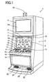
- Fig. 1 is a perspective view of the slot machine 1.
- a main display 5 is arranged at the center of which rectangular display windows 4L, 4C, 4R are formed. At the center of each of the windows 4L, 4C, 4R, one pay line 8 is described.
- reels 3L 3C, 3R are rotatably supported. On an outer periphery of each of the reels 3L 3C, 3R, a symbol row constructed from a plural kinds of symbols is described.
- the reels 3L, 3C, 3R are arranged along a horizontal line and each reel functions as a variable display device.
- the main display 5 is provided in front of the reels 3L 3C, 3R, the main display 5 being utilized for displaying images of slot games and bonus games.
- the main display 5 In the main display 5, three display windows 4L, 4C, 4R are formed.
- the main display 5 is arranged so that the symbols of each of the reels can be observed through the display windows 4L, 4C, 4R formed in the main display 5.
- the variable display device has the reels 3L, 3C, 3R as the first display portion and a liquid crystal display as the second display portion.
- a sub-display 6 for displaying the image of the bonus game is provided as the third display portion.
- a display area 5a of the main display 5 there are formed two display areas, one of which is a PAID meter 7 for indicating payouts paid out when winning combinations are got in the slot game which is a base game in the slot machine 1, and the other of which is a BET meter 9 for indicating coin numbers which can be betted in one game. And on the display area 5a of the main display 5 and at the upper of the display window 4R, a CREDIT meter 10 indicating coin number presently stored in the slot machine 1 is displayed.
- a coin insertion slot 12 into which a player inserts coins.
- a spin switch 15 for starting rotation of the reels 3L, 3C, 3R is arranged. Further, on the control panel 11, there are provided an error switch 13, a help switch 14, a cash-out switch 16, a BET switch 17, a maximum BET switch 18 and a repeat BET spin switch 19.
- the error switch 13 is a switch pressed when troubles occur in the slot machine 1, thereby an error lamp 23 arranged on a ceiling portion of the cabinet 2 is turned on. Thus, an attendant in a game arcade is called.
- the help switch 14 is pressed when the player cannot understand gaming method in the slot machine 1 or game contents of the bonus game, thereby explanation thereof is displayed on the sub-display 6.
- the cash-out switch 16 is a switch which is utilized to pay out coins stored in the slot machine 1 to a coin tray 21 from a payout chute 20.
- the BET switch 17 is a switch which is utilized when coins stored in the slot machine 1 are betted for the game. Every the BET switch 17 is pressed one time, one coin is betted. Here, the coin number betted for one game is called the "BET number".
- the maximum BET switch 18 is a switch to bet a maximum number of coins which can be betted for one game, for example, four coins for the game.
- the maximum BET switch 18 is pressed, the reels 3L, 3C, 3R are started to rotate.
- the repeat BET spin switch 19 is a switch to bet for the game the same number of coins as the BET number in the previous game and to start rotation of the reels 3L, 3C, 3R.
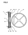
- Fig. 2 is a sectional view showing the main display 5 and the reel 3C.
- the main display 5 is constructed from a picture sheet 53 formed from the transparent film material on which various pictures are printed, the picture sheet 53 being arranged inside of an acrylic resin plate 52 functioning as a protect cover, a liquid crystal display device 54 formed from a transparent liquid crystal display device in which transparent electrodes are arranged and a light guiding plate 36.
- the picture sheet 53, the liquid crystal display device 54 and the light guiding plate 36 are stacked with each other.
- a touch panel 51 which detects coordinates corresponding to the contact area on which the player contacts.
- liquid crystal backlights 292, 293 as illumination of the liquid crystal display device 54 are arranged.
- the player By turning on the liquid crystal backlights 292, 293, the player can clearly seen and recognize the image displayed on the liquid crystal display device 54.
- symbol illumination lamps 57, 58 for illuminating the symbols on the reels 3L, 3C, 3R are arranged.
- the symbol illumination lamps 57, 58 are controlled so as to turn on when electric power is supplied, thereby the symbols on the reels 3L, 3C, 3R can be clearly seen and recognized.
- the symbol illumination lamps 57, 58 although cold cathode ray tubes are generally utilized, the present invention is not limited to this.
- the pictures described on the picture sheet 53 are always seen and recognized by the player, in spite of effect control state in the slot machine 1.
- the liquid crystal display device 54 constructs the effect area of image not only in the slot game mentioned later but also in the bonus game.
- a lamp housing 62 in which reel back lamps (not shown) turned on to easily see and recognize the symbols are installed.
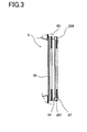
- the sub-display 6 is constructed from a picture sheet 63, a liquid crystal display device 64 and a light guiding plate 67, which are stacked with each other at the inner side of a transparent acrylic resin plate 65. And at the upper side and the lower side of the liquid crystal display device 64, liquid crystal backlights 296, 297 are provided. Since the reels are not arranged behind the sub-display 6, symbol illumination lamps are not arranged.
- main display 5 and the sub-display 6 in the slot machine 1 of the embodiment are constructed from the liquid crystal display device (LCD), the present invention is not limited to this.
- CRT or plasma display may be utilized.
- main display 5 and the sub-display 6 are constructed from one display device, the main display 5 and the sub-display 6 may be constructed from a plurality of display devices which mutually belong to different kinds.
- Fig. 4 it is shown symbol rows in each of which different kinds of symbols are arranged, the symbols being formed on the outer periphery of each reel 3L, 3C, 3R.
- the symbol row is constructed from plural kinds of symbols which are positioned at odd positions and plural blank symbols 92 positioned at even positions.
- a code number among 1 to 22 is attached and these code numbers are stored in a ROM 122 (see Fig. 9 mentioned later) as a data table.
- the "map 3" symbol 98 which includes a condor in a part of the map and completes one map picture with the "map 1" symbol 96 and the "map 2" symbol 97
- the "map 4" symbol 99 which includes a gate in a part of the map and completes one map picture with the "map 1" symbol 96 and the "map 2" symbol 97
- the map picture represents a treasure map and an item appearing in a treasure-hunting which is a theme of the slot machine 1.
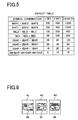
- Fig. 5 shows a payout table displayed on the sub-display 6 when the slot game, which is the base game in the slot machine 1, is conducted.
- the payout table indicates how many coins are paid out corresponding to each of the winning combinations.
- tow states one of which is the slot game and the other of which is the bonus game as the secondary game.
- the reels 3L, 3C, 3R are started to rotate by depressing the maximum BST spin switch 18 or the repeat BET spin switch 19.
- the reels 3L, 3C, 3R are stopped in a predetermined order. At that time, if the symbol combination stopped along the pay line 8 corresponds to the predetermined symbol combination, that is, the winning combinations is won, coins are paid out to the player.
- the bonus game is a game which occurs when the specific symbol combination, for example, the combination of the "map 1" symbol 96, the “map 2" symbol 97 and the “map 3" symbol 98 is stopped along the pay line 8.
- the specific symbol combination for example, the combination of the "map 1" symbol 96, the “map 2" symbol 97 and the “map 3” symbol 98 is stopped along the pay line 8.
- the description "map 1-map 2-map 3" means a case that the "map 1" symbol, the "map 2" symbol and the “map 3" symbol are stopped along the pay line 8 which positions in the center of each of the display windows 4L, 4C, 4R.
- the payouts will be described according to Fig. 5 when the symbol combinations stopped along the pay line 8 become the predetermined combinations.
- the symbol combination stopped along the pay line 8 is determined based on the probability lottery table (mentioned later) by utilizing the random number sampled every the game.
- three "2BAR"s are line up along the pay line 8 when all reels 3L, 3C, 3R are stopped, twenty coins are paid out in a case that one coins is betted, forty coins are paid out in a case that two coins are betted and sixty coins are paid out in a case that three or four coins are betted. Thus, the payout is given to the player.
- the "WILD" symbol has substitutional function for each symbol of the "1BAR” symbol, the "2BAR” symbol, the "3BAR” symbol and the "RED7” symbol, which are mentioned above.
- the "WILD” symbol substitutes for the “1BAR” and it concludes that the symbol combination "1BAR-1BAR-1BAR", that is, the winning combination "1BAR” is won.
- Fig. 6 it is shown a line up mode that the symbol combination "map 1-map 2-map 3" line up along the pay line 8 in the display windows 4L, 4C, 4R, such symbol combination forming a chance to shift to one of bonus games.
- One picture representing the treasure map is formed base on that the "map 1" symbol 96, the “map 2" symbol 97 and the “map 3" symbol 98 line up along the pay line 8.
- Fig. 7 it is shown a line up mode that the symbol combination "map 1-map 2-map 4" line up along the pay line 8, such symbol combination forming a chance to shift to another bonus game.
- one picture representing the treasure map is formed based on that the "map 1" symbol 96, the "map 2" symbol 97 and the "map 4" symbol 99 line up along the pay line 8.
- game condition shifts to the bonus game by which the specific award is given to the player. Therefore, for example, if new theme of the treasure-hunting is introduced in the gaming machine, the player can easily judge the symbol combination to shift to the bonus game as the completed one picture if the player is not accustomed to the gaming machine. Thus, the player can rapidly learn the symbol combination and can be accustomed to the game.
- the "map 1" symbol 96 and the "map 2" symbol 97 are commonly used.
- the symbol (s) if a plurality of symbol combinations giving a chance to shift to the bonus game are set, the number of symbols forming such combinations can be reduced, thereby the player can rapidly learn the symbols and can be accustomed to the game.
- one picture formed by the symbol combination in which the symbols are commonly used can easily form the common image. Therefore, the player can rapidly learn the common image and can be accustomed to the game.
- the probability lottery table is a table utilized when the symbols which line up along the pay line 8 are determined at the time that all reels 3L, 3C, 3R are stopped in the slot game.
- Fig. 8 shows the probability lottery table for the reels 3L, 3C, 3R to determine the symbols which line up along the pay line 8 when all reels 3L, 3C, 3R are stopped in a case that four coins are betted, that is, the bet number is four.
- the bet number is one ⁇ three although such tables are not shown.
- the concrete method to determine the symbol which line up along the pay line 8 by lottery is as follows.
- the CPU 21 (see Fig. 9) refers the random number value extracted from the predetermined random number range (for example, the range of 0 ⁇ 255) every each reel 3L, 3C, 3R with the probability lottery table shown in Fig. 6. Further, the CPU 21 judges that the extracted random number value lies in the random number range corresponding to which symbol and determines the symbol which line up along the pay line 8. For example, if the extracted random number value to determine the symbol on the left reel 3L lies in a range of 116 ⁇ 170, the symbol which line up along the pay line 8 when the left reel 3L is stopped becomes the "2BAR" symbol.
- the lottery is done every each reel 3L, 3C, 3R and the symbol which line up along the pay line 8 is determined
- the present invention is not limited to this.
- the winning combination corresponding to the symbol combination that is, the internal winning combination may be determined and the symbol which line up along the pay line 8 may be determined according to the internal winning combination. That is to say, the slot machine 1 may have internal winning combination determination means to determine the winning combination based on the random number value sampled every game.
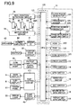
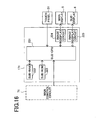
- Fig. 9 shows circuitry construction including a main control circuit 71 for controlling game process operation in the slot machine 1, periphery device (actuator) connected to the main control circuit 71 and a sub-control circuit 171 for controlling the main display 5 and the sub-display 6 based on control instruction transmitted from the main control circuit 71.
- the main control circuit 71 is mainly constructed from a microcomputer 120 arranged on a circuit board to which a circuit for sampling the random number.
- the microcomputer 120 includes the CPU 121 as a control device for conducting control operation according to a preset program and a ROM 122 and a RAM 123 which are memory means.
- a clock pulse generator 124 for generating standard clock pulses, a frequency divider 125, a random number generator 126 for generating random numbers sampled and a random number sampling circuit 127 are connected to the CPU 121.
- a clock pulse generator 124 for generating standard clock pulses, a frequency divider 125, a random number generator 126 for generating random numbers sampled and a random number sampling circuit 127 are connected to the CPU 121.
- random number generation and sampling thereof may be executed by calculation through the CPU 121 in the microcomputer 120.
- a program for controlling game in the slot machine 1 a symbol table referred when the symbols lining up along the pay line 8 are determined in a case that all reels 3L, 3C, 3R are stopped, a winning symbol combination table referred after stop control of the reels 3L, 3C, 3R is done and thereafter the reels are stopped and a probability lottery table referred when the symbols lining up along the pay line 8 are determined in a case that all reels 3L, 3C, 3R are stopped, are stored.
- ROM 122 of the microcomputer 120 various instructions (commands) for transmitting to the sub-control circuit 171.
- commands a demonstration display command, an all reels stop command, a bonus game start command to start image display of the bonus game on the sub-display 6 and the like are included.
- the sub-control circuit 171 conducts display control of the main display 5 and the sub-display 6 based on the control command from the microcomputer 120.
- the sub-control circuit 171 will be described hereinafter.
- a power amplifier 42 functioning as an amplifier for amplifying sounds output from the speaker 43 is connected to the output terminal of the CPU 121 through a sound source IC 41.
- the sound source IC 41 controls the power amplifier 42 and the speaker 43 based on the control signal such as control command output from the CPU 121.
- a coin sensor 12S for detecting coins inserted in the coin insertion slot 12 an error switch 13, a help switch 14, a spin switch 15, a cash-out switch 16, a BET switch 17, a maximum BET spin switch 18, a repeat BET spin switch 19, a reel position detection circuit 34 supplying signals to detect positions of the reels 3L, 3C, 3R to the CPU 121 based on pulse signals output from a reel position detector (not shown) and a payout completion signal circuit 36 supplying a signal to detect coin payout completion to the CPU 121 in a case that the count number counted by a coin detection portion 35, which detects coins paid out from the hopper 30, reaches to the predetermined coin number data.
- the CPU 121 supplies the payout command signal to the hopper drive circuit 32, thereby the hopper 30 pays out the predetermined number of coins.
- the coin detection portion 35 counts the number of coins paid out from the hopper 30 and when the counted number of coins reaches to the predetermined number, the coin payout completion signal is input to the CPU 121. Thereby, the CPU 121 stops drive of the hopper 30 through the hopper drive circuit 32 and coin payout process is finished.
- the main control circuit 71, the hopper 30 and the hopper drive circuit 32 constructs award providing means for providing award to the player when the symbol combination determined by stop symbol determination means and stopped along the pay line 8 becomes the predetermined display mode.
- the random number generator 126 generates random numbers within a predetermined value range and the random number sampling circuit 127 samples the random number at a voluntarily timing after the spin switch 15, the maximum BET spin switch 18 and the repeat BET spin switch 19 are pressed.
- the sample random number is determined whether such random number belongs to which range in the probability lottery table stored in the storing part in the ROM 122. If the sampled random number belongs to a predetermined range, the stop symbol signal is generated, thereby control of the reels 3L, 3C, 3R mentioned later is conducted and the determined symbol is stopped along the pay line 8.
- the number of drive pulses supplied to each of the stepping motors 49L, 49C, 49R are counted, and the counted number value is written in a predetermined area in the RAM 123.
- a reset pulse is obtained from each of the reels 3L, 3C, 3R every one rotation thereof and such reset pulses are input to the CPU 121 through the reel position detection circuit 34.
- the CPU 121 clears the counted number of drive pulses stored in the RAM 123 to "0" based on the reset pulses obtained as mentioned. Thereby, in the RAM 123, the count number value corresponding to the rotational position of each of the reels 3L, 3C, 3R within one rotation thereof.
- the symbol table is stored in the ROM 122.
- this symbol table by utilizing the rotational position generated on the basis of the above mentioned reset pulse as the standard, code number serially given every a predetermined rotation pitch of each of the reels 3L, 3C, 3R and symbol code representing the symbol provided every each code number are corresponded with each other.
- the sub-control circuit 171 is connected to the main control circuit 71.
- the main control circuit 71 including the CPU 121, the ROM 122, the clock pulse generator 124, the frequency divider 125, the random number generator 126 and the random number sampling circuit 127, constructs stop symbol determination means for determining the symbol stopped along the pay line 8 every the variable display device based on the random number value sampled every game.
- main control circuit 71 including the CPU 121 and the ROM 122 constructs stop control means for stopping and controlling variable display operation of a plurality of the variable display devices based on a determination result by the stop symbol determination means.
- the winning symbol combination table is also stored.
- the winning symbol combination table the symbol combinations corresponding to the winning combinations, the coin payout number corresponding to the winning combinations and the winning judgement codes representing the winning combinations are corresponded.
- the winning symbol combination table is referred when variable display operation of the left reel 3L, the center reel 3C and the right reel 3R is controlled to stop and when the winning combination is confirmed after all reels are stopped.
- variable display operation of the reels 3L, 3C, 3R will be described.
- all reels 3L, 3C, 3R start to rotate based on a predetermined switch operation.
- Each of the reels 3L, 3C, 3R is stopped in a predetermined order after a predetermined time is elapsed.
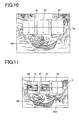
- Fig. 10 indicates a display state of the main display 5 while all reels 3L, 3C, 3R are rotating.
- the main display 5 areas for the display windows 4L, 4C, 4R are formed, and through these areas a part of each of the reels 3L, 3C, 3R which are rotating can be seen.
- Under the display windows 4L, 4C, 4R it is displayed a character 501 who is riding in a boat and going for the treasure-hunt which is the theme of the slot machine 1. Thereby, the effect of the image of treasure-hunt is conducted on the main display 5.
- Fig. 11 indicates a state that the reels 3L and 3C are serially stopped after a predetermined time is elapsed since the reels 3L, 3C, 3R start to rotate.
- the sopped reel 3L and 3C display the "map 1" symbol 96 and the "map 2" symbol 97 along the pay line 8, respectively.
- This state is the state just before game condition shifts to the bonus game based on that the remaining map symbol is displayed by the reel 3R.
- the display windows 4L, 4C, 4R it is displayed a state that the an alligator 503 attacks the character 501.
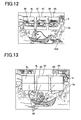
- Fig. 12 indicates a state that the reel 3R is stopped after a predetermined time is elapsed since the reels 3L and 3C are serially stopped.
- the stopped reel 3R displays the "map 3" symbol 98 along the pay line 8 and the treasure map picture is completed by combining the "map 3" symbol 98 with the "map 2" symbol 96 and the "map 2" symbol 97.
- This state indicates that game condition shifts to a condor treasure bonus game which is one of the bonus games.
- the character 501 gets rid of the alligator 503.
- the reel 3L and 3C which displays the "map 1" symbol 96 and the “map 2" symbol 97, respectively, the "map 1" symbol 96 and the “map 2" symbol 97 being commonly used, are first stopped, and the reel 3R which displays the "map 3" symbol 98 is finally stopped.
- the player can make the player recognize the probability to win the bonus game at the time that the "map 1" symbol 96 and the "map 2" symbol 97 are displayed.
- the player cannot know what kind of bonus is won till the "map 3" symbol 98 or the "map 4" symbol 99 is displayed.
- Fig. 13 indicates a state that all reels 3L, 3C, 3R are stopped after a predetermined time is elapsed since the reels 3L 3C, 3R start to rotate.
- the stopped reels 3L, 3C, 3R respectively display the symbol combination "blank-blank-blank" by the blank symbols 92. If the blank symbols 92 line up along the pay line 8, it is continuously conducted the lottery of mysterious sun bonus game which is the blank bonus. On the basis of the lottery result, if this blank bonus is realized, game condition shifts to the mysterious sun bonus game which is one of the bonus games.
- Fig. 14 indicates the display when the blank bonus is realized according to the lottery result.
- symbols 505, 506 and 507 representing the sun are displayed.
- the blank symbols 92 of the stopped reels 3L, 3C, 3R change just like to the specific symbols and line up along the pay line 8.
- the display windows 4L 4C, 4R it is displayed a state that the character 501 is surprised to find anything in the upper direction.
- the reels 3L, 3C, 3R as the variable display means display the blank symbols 92, it is determined that game condition shifts to the bonus game with a predetermined probability.
- This table is a table to determine to shift to the mysterious sun bonus game when the blank symbols 92 of the reels 3L, 3C, 3R are stopped along the pay line 8.
- the CPU 21 extracts the random number form the predetermined random number range (for example, the range of 0 ⁇ 255) and determines that the extracted random number belongs to which range in the lottery table to shift to the mysterious sun bonus game, thereafter the CPU 21 determines to shift to the mysterious sun bonus game. For example, the random number lies within the range of 0 ⁇ 5, shifting to the mysterious sun bonus game is realized.
- the predetermined random number range for example, the range of 0 ⁇ 255
- the sub-control circuit 171 is constructed from the sub-CPU 221, the sub-ROM 222, the sub-ram 223 and the image display control circuit 224, 225.
- the main control circuit 71 and the sub-control circuit 171 and between the sub-CPU 221 and each of the actuators, IN port and OUT port are voluntarily arranged.
- the sub-CPU 221 determines how to make the main display 5 and the sub-display 6 display based on a game information command transmitted from the main control circuit 71 and transmits data of display contents to the image display control circuits 224 and 225.
- a sequence program to utilized for transmission to the main control circuit 71, programs necessary for the slot game and the bonus game and various data are stored.
- the sub-ram 223 is utilized for work area when these programs are executed.
- the image display control circuit 224 has a video RAM (not shown) and controls display contents of the main display 5.
- the image display control circuit 225 has a video RAM (not shown) and controls display contents of the sub-display 6. In particular, the image display control circuit 225 controls the sub-display 6 so as to display the image of the bonus game based on a bonus game start command transmitted from the main control circuit 71.
- the touch panel 51 is connected to the sub-CPU 221.
- the touch panel 51 detects coordinate position of the portion contacted by the player and transmits information of the coordinate position to the sub-CPU 221. Thereby, the sub-CPU 221 determines which one of plural selection buttons displayed on the main display 5 is selected by the player.
- the main control circuit 71 constructs the secondary game start means to start the bonus game as the secondary game to give the specific award to the player, on condition that the symbol combination stopped along the predetermined pay line determined by the stop symbol determination means becomes the specific display mode.
- the bonus game as the secondary game will be described in detail.
- the reels 3L, 3C, 3R are not utilized, and the main display 5 and the liquid crystal display device of the sub-display 6 are used.
- the image display device different from the reels as the variable display device, it can provide the unique game freely reflecting the image of the theme of the gaming machine.
- the golden gate bonus game will be explained.
- the character sequentially passes five passing points while selecting the correct direction continuous to the next passing point on the basis of selection by the player.
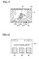
- Fig. 17 the display example of the display area 6a in the sub-display 6 is shown when the golden gate bonus game is started.
- the center position of the display area 6a it is displayed a state that the character 501 is running on the corridor toward the gate.
- a route map 622 indicating five passing points 621a, 621b, 621c, 621d and 621e is displayed.
- the accumulated points 623 obtained in the game is indicated.
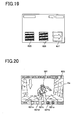
- Fig. 18 the display example of the display area 5a of the main display 5 is shown when the golden gate bonus game is started.
- the left direction arrow indication button 625 At the lower position of the display area 5a, there are displayed the left direction arrow indication button 625, the upper direction arrow indication button 626 and the right direction arrow indication button 627.
- the message "SELECT ESCAPE ROUTE" 628 At the center of the display area 6a it is displayed the message "SELECT ESCAPE ROUTE" 628 to suggest the player to conduct select operation of progress direction of the character.
- Fig. 19 sows a display example in the display area 5a when the player contacts the right direction arrow indication button 627 based on that the player selects the right progress direction.
- the slot machine 1 detects the contacted position on the touch panel 51 arranged in front of the main display 5, thereby it can be judged the button contacted by the player based on the detected position.
- the left direction arrow indication button 626 and the upper direction arrow indication button 627 both of which are not selected by the player, are darkly displayed, thereby it is indicated that the right direction arrow indication button 627 is selected.
- Fig. 20 sows a display example in the display area 6a of the sub-display 6 after the player selects the correct button. If the right direction arrow indication button 627 selected by the player is the predetermined correct button, it is displayed a state that the character 501 passes the gate of the passing point and runs on the corridor toward the next gate of the passing point. At the upper position of the display area 6a. It is displayed the score 623, for example as 20, in which the score obtained in the previous game is accumulated. And in the route map 622 displayed at the lower position of the display area 6a, the first passing point 621a is darkly displayed, thereby it is indicated that the character 501 could safely pass such passing point.
- the correct button switch is the button to clear the passing point and to progress to the next passing point, is determined in advance by the lottery before selection thereof is conducted and is made different at each of the passing points.
- the golden gate bonus is terminated and the score accumulated just before the golden gate bonus game is terminated is paid out as coins corresponding to the bonus payout of the player. If the golden gate bonus game is terminated, game condition shifts to the slot games the base game.
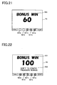
- Fig. 21 shows a display example of the display area 6a in the sub-display 6 in a case that the correct button is not selected at the fourth passing point although the correct button is selected at all of the first passing point, the second passing point and the third passing point.
- the first passing point 621a, the second passing point 621b and the third passing point 621c, which are safely passed are darkly displayed.
- the score obtained in the golden gate bonus game by the player is indicated through the message "BONUS WIN 60" 630.
- Fig. 22 shows a display example of the display area 6a in the sub-display 6 when the correct button is selected at all of the first to the fifth passing points.
- the first passing point 621a, the second passing point 621b, the third passing point 621c, the fourth passing point 621d and the fifth passing point 621e, which are safely passed are darkly displayed.
- the message "SHIFT TO THE CONDOR TREASURE BONUS" 632 in addition to the message "BONUS WIN 100" 631 is displayed.
- the condor treasure bonus game which is one of the bonus games is executed in spite of the game result in the slot game when the symbol combination "map 1-map 2-map 3" line up in the slot game and further when all selections by the player are correctly done in the golden gate bonus which is the other bonus game.
- the golden gate bonus game is conducted by the player while giving to the player probability with expectation to execute the condor treasure bonus game continuous to the golden gate bonus game, interest for bonus games can be raised.
- the condor treasure bonus game will be described.
- the player selects one treasure among five treasures only one time as the treasure that the character falling in the well picks up. And the character climbs the wall of the well according to magnification set to the selected treasure and it is given to the player coins obtained by magnifying the magnification set to the treasure with the score set to the treasure.
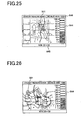
- Fig. 23 a display example of the display area 5a in the main display 5 when the condor treasure bonus is started.
- five buttons 641a, 641b, 641c, 641d, 641e, which represent five treasures respectively, are displayed.
- the message "SELECT TREASURE" 642 is displayed. This message 642 urges the player to conduct select operation of the direction toward which the character 501 goes ahead.
- the display area 6a of the sub-display 6 is entirely changed to black color to indicate that the character 501 has fallen in the well.
- Fig. 24 it is shown a display example of the display area 5a in a case that the player selects one of five treasures displayed at the lower position of the display area 5a and contacts the button 641a displayed at the most right position.
- the button 641a of the display area 5a the contacted position is detected by the touch panel 51 arranged in front of the main display 5 in the slot machine 1 and it can be judged which button is contacted based on the contacted position.
- the buttons 641b, 641c, 641d, 641e which are not contacted are darkly displayed, thereby it is indicated that only the button 641a is selected.
- buttons 641a, 641b, 641c, 641d, and 641e the score preset every button is displayed such as 300 (the button 641a), 30 (the button 641b), 150 (the button 641c), 100 (the button 641d) and 50 (the button 641a).
- the score corresponding to the selected button 641a is 50 points.
- Fig. 25 it is shown a display example of the display area 6a of the sub-display 6 after the button 641a is contacted.
- the display area 6a At the center of the display area 6a it is displayed a state that the character 501 climbs the well by means of a rope after the treasure is selected.
- the character 501 climbs the well to a predetermined position.
- the indicator 644 At the right part of the display area 6a it is displayed the indicator 644 which indicates the position that the character 501 climbs.
- the indicator 644 indicates height of the well by eleven stages.
- five stages from the bottom thereof are darkly displayed, thereby it is indicated that the character 501 climbs to the fifth stage.
- the magnification number which is magnified to the score is displayed.
- the score of the player is calculated by magnifying the magnification number corresponding to the stage to which the character reaches to the score set to the button selected by the player at the first of the game.
- the score equation "WIN 20 x 50" 645 corresponding to the state that the character 501 reaches is displayed. Further, at the upper right part of the display area 6a it is displayed the numeral "10001 as the score 646 at that time, the score 646 being obtained based on the score equation 645.
- the stage that the character 501 climbs is determined corresponding to the button selected at the first of the game by the player. That is to say, the magnification number of the score determined corresponding to the stage and the player's score determined based on the magnification number of the score are beforehand determined according to the button selected by the player at the first of the game.
- Fig. 26 it is shown a display example of the display area 6a in the sub-display 6 after the character 501 reaches to the fifth state when the stage corresponding to the button selected at the first of the game is the fifth state.
- the character 501 reaches to the state set beforehand, the character finds out an exit by kicking and breaking the wall of the well. Thereby, the condor treasure bonus game is terminated. At that time, the player's score is paid out by coins.
- game condition shifts to the slot game which is the base game.
- the mysterious sun bonus game will be described.
- the score is increased, and the character can take out the treasure till the score of fear degree through the fear item taken out by the character reaches to a predetermined upper limit.
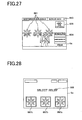
- Fig. 27 it is shown a display example of the display area 6a in the sub-display 6 when the mysterious sun bonus game is started.
- the character 501 who is facing to three relieves 661 each of which has a sun-like shape.
- the accumulated score 663 obtained in games is displayed.
- the accumulated score 663 obtained in games is displayed.
- a fear degree meter 664 which indicates a degree of fear feeling that the character 501 has.
- the character's expression 665 reflecting the fear degree is displayed at the upper position of the fear degree meter 664. In this game, the score of the fear degree is accumulated and when such score reaches to the upper limit, the game is terminated.
- Fig. 28 shows a display example of the display area 5a in the main display 5 when the mysterious sun bonus game is started. Under the display area 5a three selection buttons 667a, 667b, 667c are displayed. And in the center of the display area 5a, it is displayed the message "SELECT RELIEF" 628 which urges the player to conduct selection operation of the selection buttons 667a, 667b, 667 c.
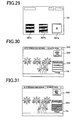
- Fig. 29 it is shown a display example of the display area 5a when the player contacts the most right selection button 667a.
- the contacted portion is detected by the touch panel 51 arranged in front of the main display 5 in the slot machine 1, thereby it can be judged the contacted selection button by the player based on the detected position.
- the selection buttons 667b and 667c not selected are darkly displayed, thereby it is indicated that the selection button 667a is selected.
- the scores 20, 10, 5 set every the selection button are displayed.
- the score set to the selection button 667a selected by the player is 5.
- To each selection button corresponding to each relief there are set one of snake, spider and specific item other than treasure, and it is displayed a state that the character takes out the item from a mouth of the relief.
- Fig. 30 it is shown a display example of the display area 6a in the sub-display 6 when the player contacts to the selection button 667a.
- the center of the display area 6a it is displayed a state that the character 501 who takes out the treasure corresponding to the selection button 667a is standing.
- the numeral 5 corresponding to the selection button 667a is displayed as the accumulated score 663.
- the expression 665 of the character who is delighted is effected and displayed.
- the mysterious sun bonus game is progressed by making the player repeatedly select.
- Fig. 31 As the example in a case that the player conducts next selection, it is shown a display example of the display area 6a in the sub-display 6 when the snake as the fear item is taken out by the character.
- the center of the display area 6a it is displayed a state that the character 501 who takes out the snake on the basis of the selection button 667a is standing.
- the accumulated score 663 displayed at the upper position of the display area 6a is held to 5.
- stages up to the three stages from the bottom are darkly displayed corresponding to the snake taken out. Thereby, it is shown that the fear degree becomes 3 points.
- the character's expression 665 reflecting the fear degree is displayed. The point of the fear degree is accumulated every the fear item is taken out and when the point reaches to the upper limit the mysterious sun bonus game is terminated.
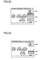
- Fig. 32 as the example in a case that the player conducts next selection, it is shown a display example of the display area 6a in the sub-display 6 when the specific item is taken out.
- the center of the display area 6a it is displayed a state that the character 501 who takes out the specific item is standing.
- the score of the fear degree is 0, two points are added to the upper limit at which the game is terminated and it is displayed in the fear degree meter 664 that the score of the fear degree becomes 7 points.
- Fig. 33 as the example in a case that the player conducts next selection, it is shown a display example of the display area 6a in the sub-display 6 when the spider as the fear item is taken out.
- the center of the display area 6a it is displayed a state that the character 501 who takes out the spider is standing.
- the spider is taken out and the score of the fear degree is 0, two points are subtracted from the upper limit at which the game is terminated.
- the fear degree meter 664 it is displayed in the fear degree meter 664 that the score of the fear degree becomes 3 points.
- the bonus game can be made longer or shorter. Accordingly, the bonus game can be conducted while retaining player's interest.
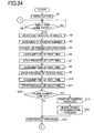
- the CPU 121 at first conducts initialization process of the main control circuit 71 in step 1 (abbreviated "S1" hereinafter). Concretely, the CPU 121 writes initial data in the RAM 123 and makes each of the actuators initial state that game can be started.
- the CPU 121 determines whether an input for stating game is done or not. Concretely, the CPU 121 determines whether the start signal from the spin switch 15, the maximum BET spin switch 18 or the repeat BET spin switch 19 is input or not. In S2, when it is determined “NO”, that is, it is determined that the start signal is not input from the spin switch 15, the maximum BET spin switch 18 or the repeat BET spin switch 19, the CPU 121 repeats process in S2. On the other hand, when it is determined "YES", that is, it is determined that the start signal is input, the CPU 121 shifts procedure to S3.
- the CPU 121 executes rotation process of the reels 3L, 3C, 3R. Concretely, the CPU 121 sends the drive signal to the motor drive circuit 31 and drives the reels 3L, 3C, 3R to rotate.
- the CPU 121 conducts random number sampling.
- the CPU 121 sends the signal to generate random numbers to the random number generator 126 and makes the random number sampling circuit 127 extract a random number every each of three reels 3L, 3C, 3R. And the CPU 121 stores the extracted random number value in a predetermined area of the RAM 123.
- the CPU 121 executes symbol determination process.
- the CPU 121 judges that the random number value stored in the RAM 123 belongs to which range of the probability lottery table stored beforehand in the ROM 122, every each of three reels 3L, 3C, 3R, and determines the symbols to be stopped along the pay line 8. And the CPU 121 stores determined symbols.
- the symbol determination process is done by S4 and S5.
- the CPU 121 conducts consumption of wait time, thereafter in S7 the CPU 121 executes stop process of the left reel 3L.
- the CPU 121 sends the signal to stop and control the variable display operation of the left reel 3L to the motor drive circuit 31, corresponding to the determined stop symbol.
- the motor drive circuit 31 stops the left reel 3L through the stepping motor 49L.
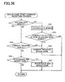
- the CPU 121 judges whether the blank symbols line up along the pay line 8. In this step, in a case that it is judged that the blank symbols line up along the pay line 8, the CPU 121 shifts procedure to S13. On the other hand, when it is judged "NO", that is, it is judged that the blank symbols do not line up along the pay line 8, he CPU 121 shifts procedure to S15.
- the CPU 121 conducts random number sampling to determine start of the mysterious sun bonus game as the blank bonus.
- the CPU 121 sends the signal to generate random number to the random number generator 126, thereby the CPU 121 makes the random number sampling circuit 127 extract a random number.
- the CPU 121 stores the extracted random number value in a predetermined area of the RAM 123.
- the CPU 121 conducts blank bonus determination process. Concretely, with reference to the table sown in Fig. 15, the CPU 121 determines whether the random number value stored in S13 belongs to the case that the mysterious sun bonus game is activated or to the case that the mysterious sun bonus game is not activated.
- the CPU 121 pays out coins according to the winning combination on the basis of the symbol combination stopped along the pay line 8 when the reels 3L, 3C, 3R are stopped and the bet number betted by the player.
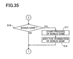
- the CPU 121 judges whether the bonus game is executed or not. If the bonus game is executed, the CPU 121 shifts procedure to S 17. On the other hand, if the bonus game is not executed, the CPU 121 shifts procedure to S2 (Fig. 34).
- the CPU 121 conducts start process of the bonus game.
- the CPU 121 sends the bonus start command with information of kind of the bonus game to the sub-CPU 221.
- function of the bonus start means is realized.
- the CPU 121 waits for termination of the bonus game. Since execution of the bonus game is mainly done by the sub-CPU 221, the CPU 121 stops the slot game as the base game till the bonus game is terminated by the sub-CPU 221.
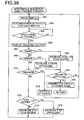
- the sub-CPU 221 judges whether the kind of the bonus is the golden gate bonus or not. Concretely, the sub-CPU 221 judges whether the information concerning with the kind of the bonus game accompanied by the bonus game start command. In this step, if it is judged "YES”, that is, it is judged that the golden gate bonus game is started, the sub-CPU 221 shifts procedure to S32. On the other hand, if it is judge "NO”, that is, it is judged that the golden gate bonus game is not started, the sub-CPU 221 shifts procedure to S34.
- the sub-CPU 221 conducts golden gate bonus game process. As for the process in this step, it will be described hereafter.
- the sub-CPU 221 judges whether the correct selection is done or not by the player in the golden gate bonus game (S32). Concretely, it is judged whether or not the buttons indicating the predetermined direction by which the next passing point is led are selected by the player in all of five passing points, and the character 501 reaches to the goal. In this step, it is judged "YES”, that is, if it is judged that the correct selections are done, the sub-CPU 221 shifts procedure to S35. On the other hand, if it is judged "NO”, that is, it is judged that at least one correct selection is not done, the sub-CPU 221 terminates this routine.
- the sub-CPU 221 judges whether the kind of the bonus is the condor treasure bonus or not. In this step, if is judged "YES”, that is, it is judged that the condor treasure bonus game is started, the sub-CPU 221 shifts procedure to S35. On the other hand, if it is judged "NO”, that is, it is judged that the condor treasure bonus game is not started, the sub-CPU 221 shifts procedure to S36.
- the sub-CPU 221 conducts condor treasure bonus game process. As for the process in this step, it will be described hereinafter. After this step, the sub-CPU 221 terminates this routine.
- the condor treasure bonus game which is at least one of plural bonus games, is conducted in any of both cases that plural reels as the variable display means are stopped with the specific symbol combination "map 1-map 2-map 3" and that it can be obtained the specific result in which the character can reach to the goal in the golden gate bonus game as the other bonus game
- the golden gate bonus game in which the paler takes part in while conducting various selection, if a predetermined condition is satisfied, it is determined whether or not game condition shifts to the condor treasure bonus game which is the other bonus game. Therefore, since the player conducts the bonus game while expecting that the player may continuously enjoy the other bonus game, interest for games can be raised.
- the sub-CPU 221 judges whether the kind of the bonus game is the mysterious sun bonus game or not. In this step, if it is judged "YES”, that is, it is judged that the mysterious sun bonus game is started, the sub-CPU 221 shifts procedure to S 37. On the other hand, if it is judged "NO”, that is, it is judged that the mysterious sun bonus game is not started, the sub-CPU 221 terminates this routine.
- the sub-CPU 221 executes mysterious sun bonus game process. As for the process in this step, it will be described hereinafter. After this step is done, the sub-CPU 221 terminates this routine.
- the sub-CPU 221 conducts image display process. Concretely, the sub-CPU 221 sends the image display command to the image display control circuit 224 in order to display the image shown in Fig. 18 in the display area 5a of the main display 5, and sends the image display command to the image display control circuit 225 in order to display the image shown in Fig. 17 in the display area 6a of the sub-display 6.
- the sub-CPU 221 conducts selection process according to the correct direction at the present passing point. Concretely, the sub-CPU 221 generates random number by calculation and determines based on the generated random number which is the button with the predetermined correct direction among the left direction arrow indication button 625, the upper direction arrow indication button 626 and the right direction arrow indication button 627.
- the sub-CPU 221 judges whether the touch panel 51 is contacted or not. In this step, if it is judged "YES”, that is, it is judged that the touch panel 51 is contacted by the player, the sub-CPU 221 shifts procedure to S 44. On the other hand, if is judged "NO”, that is, it is judged that the touch panel 51 is not contacted by the player, S43 is repeated.
- the sub-CPU 221 conducts button display process concerning with the selected button. Concretely, the sub-CPU 221 judges the selected button based on the coordinate position information of the contacted portion output from the touch panel 51, and as shown in Fig. 19, the sub-CPU 221 sends the image display command to the image display control circuit 224 in order to darkly display the buttons other than the selected button.
- the sub-CPU 221 judges whether the direction selected by the player is correct direction or not. Concretely, the sub-CPU 221 judges whether not the selected button in S44 coincides with the button with the predetermined correct direction determined in S42. In this step, if it is judged "YES", that is, it is judged that the button is the button with the predetermined correct direction, the sub-CPU 221 shifts procedure to S46. On the other hand, if it is judged "NO”, that is, it is judged the button is not the button with the predetermined correct direction, the sub-CPU 221 shifts procedure to S 50.
- the sub-CPU 221 conducts image display process indicating that the character succeeds to pass the passing points. For example, the sub-CPU 221 sends the image display command to the image display control circuit 224 in order to display the image that the character 501 passes the gates on the sub-display 6.
- the sub-CPU 221 conducts addition process of the score.
- the sub-CPU 221 adds the points set to the present passing point to the score as the points obtained by the player.
- the sub-CPU 221 judges whether or not the present passing point is the fifth passing point, that is, the final passing point. In this step, if is judged "YES”, that is, it is judged that the present passing point is the final passing point, the sub-CPU 221 terminates the game and shifts procedure to S 49 in order to shift to the other bonus game. On the other hand, if it is judged "NO”, that is, it is judged that the present passing point lies between the first passing point and the fourth passing point, the sub-CPU 221 shifts procedure to S41 and game is repeated.
- the sub-CPU 221 conducts the process to shift to the condor treasure bonus game. Concretely, the sub-CPU 221 sends the image display command to the image display control circuit 225 in order to display the image shown in Fig, 21. The sub-CPU 221 terminates this routine after the process in this step is done.
- the sub-CPU 221 conducts the display process indicating that the ordinal bonus game is terminated. Concretely, the sub-CPU 221 sends the image display command to the image display control circuit 225 in order to display the image shown in Fig. 21. The sub-CPU 221 terminates this routine after the process in this state is done.
- the sub-CPU 221 conducts the image display process. Concretely, the sub-CPU 221 sends the image display command to the image display control circuit 224 in order to display the image shown in Fig. 23 in the display area 5a of the main display 5. And the sub-CPU 221 sends the image display command to the image display control circuit 225 in order to display the image entirely colored with black color in the display area 6a of the sub-display 6.
- the sub-CPU 221 conducts payout determination process for each button displayed on the display area 5a.
- the sub-CPU 21 generates random number by calculation and based on the generated random number the sub-CPU 221 gives, for example, 300 points, 30 points, 150 points, 100 points, 50 points for each of five switches 641a, 641b, 641c, 641d, 641 d, 641e, respectively, the switches representing treasures displayed on the display area 5a.
- the sub-CPU 221 arranges the stages which the character climbs for each of the buttons.
- the sub-CPU 221 judges whether the touch panel 51 is contacted or not. Concretely, in this step, if it is judged "YES”, that is, it is judged that the button representing portion on the touch panel 51 is contacted by the player, the sub-CPU 221 shifts procedure to S54. On the other hand, if it is judged "NO”, that is, it is judged that the touch panel 51 is not contacted, the sub-CPU 221 repeats process in S53.
- the sub CPU 221 conducts display process of the selected button. Concretely, the sub-CPU 221 judges the selected button based on the coordinate position information of the contacted portion output from the touch panel 51, and as shown in Fig. 24, the sub-CPU 221 sends the image display command to the image display control circuit 224 in order to darkly display the buttons other than the selected button.
- the sub-CPU 221 conducts display process of the image so that the character 501 climbs up one stage, corresponding to the selected button by the player. Concretely, the sub-CPU 221 displays the image shown in Fig. 25 on the display area 6a.
- the sub-CPU 221 judges whether the character 501 climbs the well by the predetermined stages. Concretely, the sub-CPU 221 judges whether or not the process that the character 501 climbs the well by states as same as the stages arranged corresponding to the button selected in S54 is done. In this step, if it is judged "YES", that is, it is judged that the character climbs the well by the predetermined stages, the sub-CPU 221 shifts procedure to S57. ON the other hand, if it is judged "NO”, that is, it is judged that the character does not climb the well by the predetermined stages, the sub-CPU 221 shifts procedure to S55 and repeats the display that the character climbs the well.
- the sub-CPU 221 judges whether or not the character climbs the well by 10 stages, that is, whether or not the character climbs up the well. In this step, if it is judged "NO”, that is, it is judged that the character does not climb by 10 stages, the sub-CPU 221 shifts procedure to S 58 in order to terminate the game by finding out the exit. On the other hand, if is judged that "YES”, that is, it is judged that the character climbs the well by 10 stages, the sub-CPU 221 shifts procedure to S59 in order to terminate the game by climbing up the well.
- the sub-CPU 221 conducts game termination display process by finding out the exit.
- the sub-CPU 221 sends image display command to the image display control circuit 225 in order to display the image shown in Fig. 26 on the display area 6a. And the sub-CPU 221 terminates this routine after this step is done.
- the sub-CPU 221 game termination display process by climbing up the well.
- the sub-CPU 221 sends image display command to the image display control circuit 225 in order to display the top image of the well on the display area 6a.
- the sub-CPU 221 terminates this routine after this step is done
- the sub CPU 221 conducts image display process. Concretely, the sub-CPU 221 sends the image display command to the image display control circuit 224 in order to display the image shown in Fig. 28 on the display area 5a of the main display 5 and sends image display command to the image display control circuit 225 in order to display the image shown in Fig. 27 on the display area 6a of the sub-display 6.
- the sub-CPU 221 conducts payout determination process of each of the buttons displayed on the display area 5a.
- the sub-CPU 221 generates random number by calculation and based on the generated random number the sub-CPU 221 arranges, for example, 20 points, 10 points, 5 points corresponding to each of three buttons 667a, 667b, 667c, the buttons representing treasures displayed on the display area 5a.
- the sub-CPU 221 selects the item to be taken out among the treasure, the snake, the spider, the specific item for each button.
- the sub-CPU 221 judges whether the touch panel 51 is contacted or not. Concretely, in this step, if it is judged "YES", that is, it is judged that the portion where the button of the touch panel 51 is displayed is contacted by the player, the sub-CPU 221 shifts procedure to S64. On the other hand, if it is judged "NO”, that is, it is judged that the touch panel 51 is not contacted, the sub-CPU 221 repeats process in S63.
- the sub-CPU 221 conducts display process of the selected button. Concretely, the sub-CPU 221 judges the selected button based on the coordinate position information of the contacted portion output from the touch panel 51, and as shown in Fig. 29, the sub-CPU 221 sends the image display command to the image display control circuit 224 in order to darkly display the buttons other than the selected button.
- the sub-CPU 221 judges whether or not the item arranged in the relief corresponding to the selected button by the player is the snake. In this step, if it is judged "YES”, that is, it is judged that such item is the snake, the sub-CPU 221 shifts procedure to S66. On the other hand, if it is judged "NO”, that is, it is judged that such item is not the snake, the sub-CPU 221 shifts procedure to S69.
- the sub-CPU 221 conducts accumulation process to add points corresponding to the snake to the fear degree score.
- the sub-CPU 221 judges whether or not the accumulated score of the fear degree reaches to the upper limit. In this step, if it is judged "YES”, that is, it is judged that the score of the fear degree reaches to the upper limit, the sub-CPU 221 shifts procedure to S68. On the other hand, it is judged "NO”, that is, it is judged that the score of the fear degree does not reach to the upper limit, the sub-CPU 221 shifts procedure to S 61 in order to continue the bonus game.
- function of the bonus termination judgement means is realized.
- the initial value of the fear degree is set to a constant value, for example 5 points, at the start of the mysterious sun bonus game.
- the sub-CPU 221 conducts bonus game termination display process.
- the sub-CPU 221 judges whether or not the item arranged in the relief corresponding to the selected button by the player is the spider. In this step, if it is judged "YES”, that is, it is judged that such item is the spider, the sub-CPU 221 shifts procedure to S70. On the other hand, if it is judged "NO”, that is, it is judged that such item is not the spider, the sub-CPU 221 judges that such item is the specific item and shifts procedure to S71.
- the sub-CPU 221 conducts the process to subtract 2 points from the upper limit of the fear degree.
- the sub-CPU 221 shifts procedure to S67 after the process in this step is done.
- the sub-CPU 221 judges whether or not the item arranged in the relief corresponding to the selected button by the player is the treasure. In this step, if it is judged "YES”, that is, it is judged that such item is the treasure, the sub-CPU 221 shifts procedure to S73. On the other hand, if it is judged "NO”, that is, it is judged that such item is not the treasure, the sub-CPU 221 shifts procedure to S73.
- the sub-CPU 221 conducts addition process of the score.
- the sub-CPU 221 shifts procedure to S61 after the process in this step is done.
- the sub-CPU 221 judges whether or not the score of the present fear degree is 0. In this step, if it is judged "YES”, that is, it is judged that the score of the fear degree is 0, the sub-CPU 221 shifts procedure to S75. On the other hand, if it is judged "NO”, that is, it is judged that the score of the fear degree is not 0, the sub-CPU 221 shifts procedure to S74.
- the sub-CPU 221 conducts the process to subtract 2 points of the score of the fear degree.
- the sub-CPU 221 terminates this routine after the process in this step is done.
- the sub-CPU 221 conducts the process to add 2 points to the upper limit.
- the accumulated value of the score of the fear degree is added, thereby the time that the bonus game is terminated is lengthened.
- the sub-CPU 221 terminates this routine after the process in this step is done.
- the score of the fear degree which is accumulated corresponding to progress of the mysterious sun bonus game is determined and function of the measurement means to add to or subtract from the upper limit is realized
- variable display device is constructed from the reels which are rotated
- the present invention is not limited to this.
- symbol images are sequentially displayed in the LCD or CRT.
- the symbol not commonly used may be included according to the symbol combination corresponding to the symbol combination to shift to the bonus game.
- the other bonus game in a case that the specific result is obtained based on the player's selection in one bonus game, the other bonus game is executed.
- the bonus game is not limited to one. And in a case that the specific result is obtained based on the player's selection in one of plural bonus games, the other bonus game may be continuously executed.
- the blank bonus determination means determined the bonus with a predetermined probability
- it is utilized the table in which random numbers are fixed.
- the predetermined probability may be changed. For example, such probability may be changed according to the state that the winning combination is realized at the predetermined past time.
- the upper limit which becomes the standard to terminate the bonus game is added or subtracted only when the predetermined item such as the spider or the specific item is selected, the present invention is not limited to this.
- the upper limit may be added or subtracted according to the treasure determining the score.
- the score of the fear degree is utilized as the points to judge the termination of the bonus game, the score obtained by taking out the treasure may be utilized.
Abstract
Description
- The present invention relates to a gaming machine, and in particular, relates to a gaming machine such as a slot machine, a Japanese pachi-slot machine, a video poker gaming machine, the gaming machine having a variable display device for displaying a plural kinds of symbols necessary for a game and a controller such as a microcomputer for conducting stop control of the variable display device.
- Conventionally, as the gaming machines mentioned above, there exists, for example the slot machine. Game in the slot machine is started by inserting medals therein or betting medals within the number of medals credited in the slot machine, and thereafter by operating a start lever or spin button by a player. When the game in the slot machine is started, reels on which a plurality of symbols are described start to rotate and thereafter each of the reels is stopped in a predetermined order. And if the winning combination is won according to the symbol combination displayed by the reels, medals are paid out to the player. And one game is terminated.
- The slot machines in current at present have plural modes of winning combinations. In particular, when the predetermined winning combination is won, a gaming state more beneficial for the player than the base game is obtained for a predetermined time, in addition to one time of medal payout. As such winning combination, there is a bonus game in which games giving a relatively large award to the player can be done. And the gaming machine such as the slot machine has decoration parts and display devices to joyfully effect the above award. These decoration parts or the display devices are generally designed so as to reflect the image of theme set in every gaming machine. And characters or things or background pictures according to the theme are displayed on the cabinet of display panel to exercise the machine's ingenuity. Further, as shown in Japanese Unexamined Patent Publication No. 2003-62177, it is known the gaming machine in which these pictures are displayed on the reels as the symbols.
- However, the symbols described on the reels has function to inform the winning combination including the bonus of the player, the winning combination being determined when the reels are stopped. Therefore, if the symbols are designed by reflecting the image of the machine's own theme, there is a case that it is difficult for the player not accustomed to the gaming machine to recognize whether the winning combination is realized or not. Further, if a plurality of bonuses capable of being won are set and the symbols based on the characteristic theme are described on the reels, there will be fear that it takes long time for the player to learn the symbol corresponding to the bonus and to be accustomed to the game. And if each of the symbol combinations corresponding to plural bonuses is constructed from the symbols reflecting the machine's own image, it can be predicted which bonus among plural bonuses will be won at the time that the first reel is stopped. Thus, it lacks in interest and the player loses interest for the game.
- The present invention has been done to dissolve the above problems and has an object to provide a gaming machine in which it can be easily judged that the bonus is won even if the symbols displayed on the variable display device such as reels are designed so as to reflect an image of theme concerning with the gaming machine.
- In order to accomplish the above object, according to one aspect of the present invention, it is provided a gaming machine comprising:
- a plurality of variable display devices for variably displaying plural kinds of symbols utilized in a game;
- a stop symbol determination device for determining the symbols stopped along a pay line every each of the variable display devices based on a random number value sampled every game; and
- a stop controller for conducting stop control of variable display in the variable display devices based on a determination result determined by the stop symbol determination device; wherein symbol combinations each of which is constructed from the symbols determined by the stop symbol determination device include a plurality of specific display modes each of which corresponds to a specific award, and
-
- According to the gaming machine, at least two of the specific display modes, which are included in the symbol combinations and each of which corresponds to a specific award, form one picture and at least one symbol is commonly utilized in the specific display mode. Thereby, the specific award is easily indicated to the player through the method that the symbol combination displays one picture. Further, plural symbol combinations corresponding to plural bonuses are constructed from at least one symbol which is commonly utilized. Therefore, even in the complexed gaming machine in which it is designed so that the image of the theme concerning with the gaming machine is reflected on the symbols described on the reels and a plural kinds of bonuses are set, if the symbol is commonly utilized, it can be shown to the player that any specific display mode can be realized. Thereby, even in a case that the player is not accustomed to the gaming machine, the player can easily judge whether or not the specific display mode is determined.
- And in a case that the symbol which is commonly utilized is first displayed when the variable display device is stopped, it can be judged whether or not the specific display mode is realized. However, it cannot be judged the kind of the specific display mode till the other reels are stopped. Therefore, interest for games can be raised if the gaming machine is constructed so that the kind of the specific display mode cannot be predicted at early stage of the game.
- And according to another aspect of the present invention, it is provided a gaming machine comprising:
- a plurality of variable display devices for variably displaying a plurality of symbols utilized in a base game;
- a stop symbol determination device for determining the symbols variably displayed on the variable display devices based on a random number value sampled every game;
- a bonus game execution device for executing a bonus game corresponding to specific symbols among a plurality of bonus games when variable display of the variable display devices is stopped while the specific symbols are stopped and displayed through the variable display devices; wherein at least one bonus game is executed when the variable display devices are stopped with the specific symbols or when a specific result is obtained in another bonus game.
-
- According to the gaming machine, at least one bonus game among a plurality of bonus games executed in the gaming machine is executed when the variable display devices are stopped with the specific symbols or when a specific result is obtained in another bonus game by the player's selection. Thereby, in the bonus game in which the player participates while conducting various selection, if the predetermined condition is satisfied, it is determined whether or not game condition shifts to another bonus game. Therefore, the player can enjoy the bonus game while expecting to continuously conduct another bonus game, thus interest for games can be raised.
- Further, according to another aspect of the present invention, it is provided a gaming machine comprising:
- a plurality of variable display devices for variably displaying a plurality of symbols utilized in a game;
- a stop symbol determination device for determining a symbol combination stopped at a predetermined position in the variable display devices based on a random number value sampled every game;
- a stop control device for conducting stop control of the variable display devices based on a result determined by the stop symbol determination device; and
- a blank bonus determination device for determining winning of the bonus with a predetermined probability when blank symbols are stopped at the predetermined positions.
-
- According to the gaming machine, the blank bonus determination device determines winning of the bonus with a predetermined probability when blank symbols are stopped at the predetermined positions. Thereby, even if the blank symbols are displayed on the variable display devices, not only the game is merely terminated but also there remains a probability to occur the bonus game. Therefore, the player has unexpected feeling and interest for games can be raised.
- According to further another aspect of the present invention, it is provided a gaming machine comprising:
- a plurality of variable display devices for variably displaying a plurality of symbols utilized in a game;
- a stop symbol determination device for determining symbols stopped at predetermined positions in the variable display devices based on a random number value sampled every game;
- a bonus game start device for starting a bonus game when the variable display devices are stopped with specific symbols;
- a measurement device for determining a score accumulated according to progress of the bonus game and for increasing or decreasing an upper limit of the score; and
- a bonus game termination device for terminating the bonus game when the score exceeds the upper limit.
-
- According to the gaming machine, in the bonus game activated when the variable display devices of the gaming machine stop variable display with the specific symbols, the measurement device determines the score while accumulating according to progress of the bonus game and the bonus game determination device terminates the bonus game when the score exceeds the upper limit. That is to say, the bonus game is progressed till the score reaches to the upper limit. Thereby, it can roughly indicate to the player when the bonus game is terminated. Therefore, the player can predict the termination of the bonus game to some extent. Thus, there scarcely occurs a case that the bonus game is suddenly terminated contrary to the player's expectation. Accordingly, the bonus game can be done while retaining interest of the player and the base game which is restarted continuous to the bonus game can be conducted.
- The above and further objects and novel features of the invention will more fully appear from the following detailed description when the same is read in connection with the accompanying drawings. It is to be expressly understood, however, that the drawings are for purpose of illustration only and not intended as a definition of the limits of the invention.
- The accompanying drawings, which are incorporated in and constitute a part of this specification illustrate embodiments of the invention and, together with the description, serve to explain the objects, advantages and principles of the invention.
- In the drawings,
- Fig. 1 is a perspective view showing a slot machine according to the embodiment,
- Fig. 2 is a sectional view of a main display in the slot machine according to the embodiment,
- Fig. 3 is a sectional view of a sub-display in the slot machine according to the embodiment,
- Fig. 4 is an explanatory view showing symbol rows each of which is described on each reel in the slot machine according to the embodiment,
- Fig. 5 is an explanatory view of a payout table utilized in the slot machine according to the embodiment,
- Fig. 6 is an explanatory view showing one example of symbol combination utilized in the slot machine according to the embodiment,
- Fig. 7 is an explanatory view showing one example of symbol combination utilized in the slot machine according to the embodiment,
- Fig. 8 is an explanatory view showing one example of probability lottery table corresponding to each of the reels, the probability lottery table being utilized in the slot machine according to the embodiment,
- Fig. 9 is an explanatory view showing a block diagram of electric circuits utilized in the slot machine according to the embodiment,
- Fig. 10 is an explanatory view showing one example of variable display motion of the reels conducted in the slot machine according to the embodiment,
- Fig. 11 is an explanatory view showing one example of variable display motion of the reels conducted in the slot machine according to the embodiment,
- Fig. 12 is an explanatory view showing one example of variable display motion of the reels conducted in the slot machine according to the embodiment,
- Fig. 13 is an explanatory view showing one example of variable display motion of the reels conducted in the slot machine according to the embodiment,
- Fig. 14 is an explanatory view showing one example of variable display motion of the reels conducted in the slot machine according to the embodiment,
- Fig. 15 is an explanatory view showing a lottery table to determined whether a bonus game is realized or not, the lottery table being utilized in the slot machine according to the embodiment,
- Fig. 16 is an explanatory view showing a block diagram of electric circuits in a sub-control circuit utilized in the slot machine according to the embodiment,
- Fig. 17 is an explanatory view showing an image of the bonus game utilized in the slot machine according to the embodiment,
- Fig. 18 is an explanatory view showing an image of the bonus game utilized in the slot machine according to the embodiment,
- Fig. 19 is an explanatory view showing an image of the bonus game utilized in the slot machine according to the embodiment,
- Fig. 20 is an explanatory view showing an image of the bonus game utilized in the slot machine according to the embodiment,
- Fig. 21 is an explanatory view showing an image of the bonus game utilized in the slot machine according to the embodiment,
- Fig. 22 is an explanatory view showing an image of the bonus game utilized in the slot machine according to the embodiment,
- Fig. 23 is an explanatory view showing an image of the bonus game utilized in the slot machine according to the embodiment,
- Fig. 24 is an explanatory view showing an image of the bonus game utilized in the slot machine according to the embodiment,
- Fig. 25 is an explanatory view showing an image of the bonus game utilized in the slot machine according to the embodiment,
- Fig. 26 is an explanatory view showing an image of the bonus game utilized in the slot machine according to the embodiment,
- Fig. 27 is an explanatory view showing an image of the bonus game utilized in the slot machine according to the embodiment,
- Fig. 28 is an explanatory view showing an image of the bonus game utilized in the slot machine according to the embodiment,
- Fig. 29 is an explanatory view showing an image of the bonus game utilized in the slot machine according to the embodiment,
- Fig. 30 is an explanatory view showing an image of the bonus game utilized in the slot machine according to the embodiment,
- Fig. 31 is an explanatory view showing an image of the bonus game utilized in the slot machine according to the embodiment,
- Fig. 32 is an explanatory view showing an image of the bonus game utilized in the slot machine according to the embodiment,
- Fig. 33 is an explanatory view showing an image of the bonus game utilized in the slot machine according to the embodiment,
- Fig. 34 is a flowchart executed in a main control circuit in the slot machine according to the embodiment,
- Fig. 35 is a flowchart executed in the main control circuit in the slot machine according to the embodiment,
- Fig. 36 is a flowchart executed in the sub-control circuit in the slot machine according to the embodiment,
- Fig. 37 is a flowchart executed in the sub-control circuit in the slot machine according to the embodiment,
- Fig. 38 is a flowchart executed in the sub-control circuit in the slot machine according to the embodiment, and
- Fig. 39 is a flowchart executed in the sub-control circuit in the slot machine according to the embodiment.
-
- Hereinafter, one example of the preferred embodiment according to the present invention will be described with reference to the drawings. As game media utilized in the gaming machine, coins, medals, tokens are generally used. Here, explanation of the gaming machine in which coins are utilized will be done.
- The
slot machine 1 according to one embodiment is shown in Fig. 1, which is a perspective view of theslot machine 1. - In front of a
cabinet 2 which wholly constructs thegaming machine 1, amain display 5 is arranged at the center of whichrectangular display windows windows pay line 8 is described. - At the front side of the
slot machine 1 in thecabinet 2, threereels 3L 3C, 3R are rotatably supported. On an outer periphery of each of thereels 3L 3C, 3R, a symbol row constructed from a plural kinds of symbols is described. Thereels - In the
cabinet 2, themain display 5 is provided in front of thereels 3L 3C, 3R, themain display 5 being utilized for displaying images of slot games and bonus games. In themain display 5, threedisplay windows main display 5 is arranged so that the symbols of each of the reels can be observed through thedisplay windows main display 5. The variable display device has thereels cabinet 2, asub-display 6 for displaying the image of the bonus game is provided as the third display portion. - On a
display area 5a of themain display 5, there are formed two display areas, one of which is aPAID meter 7 for indicating payouts paid out when winning combinations are got in the slot game which is a base game in theslot machine 1, and the other of which is aBET meter 9 for indicating coin numbers which can be betted in one game. And on thedisplay area 5a of themain display 5 and at the upper of thedisplay window 4R, aCREDIT meter 10 indicating coin number presently stored in theslot machine 1 is displayed. - In a
control panel 11 arranged under themain display 5, it is formed acoin insertion slot 12 into which a player inserts coins. - And on the
control panel 11, aspin switch 15 for starting rotation of thereels control panel 11, there are provided anerror switch 13, ahelp switch 14, a cash-out switch 16, aBET switch 17, amaximum BET switch 18 and a repeatBET spin switch 19. - Here, the
error switch 13 is a switch pressed when troubles occur in theslot machine 1, thereby anerror lamp 23 arranged on a ceiling portion of thecabinet 2 is turned on. Thus, an attendant in a game arcade is called. - The
help switch 14 is pressed when the player cannot understand gaming method in theslot machine 1 or game contents of the bonus game, thereby explanation thereof is displayed on thesub-display 6. - The cash-
out switch 16 is a switch which is utilized to pay out coins stored in theslot machine 1 to acoin tray 21 from apayout chute 20. - The
BET switch 17 is a switch which is utilized when coins stored in theslot machine 1 are betted for the game. Every theBET switch 17 is pressed one time, one coin is betted. Here, the coin number betted for one game is called the "BET number". - The
maximum BET switch 18 is a switch to bet a maximum number of coins which can be betted for one game, for example, four coins for the game. When themaximum BET switch 18 is pressed, thereels - The repeat
BET spin switch 19 is a switch to bet for the game the same number of coins as the BET number in the previous game and to start rotation of thereels - And at the upper side of the
coin tray 21, which becomes a receiving dish for coins paid out from thepayout chute 20, there are formed speaker grills 22 to output toward outside of thecabinet 2 sounds emitted from speakers 43 (see Fig. 9) installed in thecabinet 2. - With reference to Fig. 2, construction of the
main display 5 will be described. - Fig. 2 is a sectional view showing the
main display 5 and thereel 3C. Themain display 5 is constructed from apicture sheet 53 formed from the transparent film material on which various pictures are printed, thepicture sheet 53 being arranged inside of anacrylic resin plate 52 functioning as a protect cover, a liquidcrystal display device 54 formed from a transparent liquid crystal display device in which transparent electrodes are arranged and alight guiding plate 36. Thepicture sheet 53, the liquidcrystal display device 54 and thelight guiding plate 36 are stacked with each other. And in front of themain display 5, it is arranged atouch panel 51 which detects coordinates corresponding to the contact area on which the player contacts. - And at the upper side and the lower side of the liquid
crystal display device 54, liquid crystal backlights 292, 293 as illumination of the liquidcrystal display device 54 are arranged. By turning on the liquid crystal backlights 292, 293, the player can clearly seen and recognize the image displayed on the liquidcrystal display device 54. - At the inner upper side and the lower side of the
main display 5,symbol illumination lamps reels symbol illumination lamps reels symbol illumination lamps - The pictures described on the
picture sheet 53 are always seen and recognized by the player, in spite of effect control state in theslot machine 1. The liquidcrystal display device 54 constructs the effect area of image not only in the slot game mentioned later but also in the bonus game. - Near the front inner side of the
reels lamp housing 62 in which reel back lamps (not shown) turned on to easily see and recognize the symbols are installed. - In Fig. 3, the sectional of the
sub-display 6 is shown. Similar to themain display 5, thesub-display 6 is constructed from apicture sheet 63, a liquidcrystal display device 64 and alight guiding plate 67, which are stacked with each other at the inner side of a transparentacrylic resin plate 65. And at the upper side and the lower side of the liquidcrystal display device 64, liquid crystal backlights 296, 297 are provided. Since the reels are not arranged behind thesub-display 6, symbol illumination lamps are not arranged. - Although the
main display 5 and the sub-display 6 in theslot machine 1 of the embodiment are constructed from the liquid crystal display device (LCD), the present invention is not limited to this. For example, CRT or plasma display may be utilized. And although themain display 5 and thesub-display 6 are constructed from one display device, themain display 5 and thesub-display 6 may be constructed from a plurality of display devices which mutually belong to different kinds. - In Fig. 4, it is shown symbol rows in each of which different kinds of symbols are arranged, the symbols being formed on the outer periphery of each
reel blank symbols 92 positioned at even positions. To each symbol, a code number among 1 to 22 is attached and these code numbers are stored in a ROM 122 (see Fig. 9 mentioned later) as a data table. On each of thereels symbol 91 represented by the word "WILD", the "1BAR"symbol 100 represented by one "BAR", the "2BAR"symbol 93 represented by two "BAR"s, the "3BAR"symbol 94 represented by three "BAR"s and the "RED7"symbol 95 represented by the red numeral "7" are described. And on thereel 3L, the "map 1"symbol 96 which shows a part of the map is described. On thereel 3C, the "map 2"symbol 97 which shows another part of the map is described. Further, on thereel 3R, the "map 3"symbol 98, which includes a condor in a part of the map and completes one map picture with the "map 1"symbol 96 and the "map 2"symbol 97, is described. Further, on thereel 3R, the "map 4"symbol 99, which includes a gate in a part of the map and completes one map picture with the "map 1"symbol 96 and the "map 2"symbol 97, is described. Here, the map picture represents a treasure map and an item appearing in a treasure-hunting which is a theme of theslot machine 1. Thus, by representing things concerning with the theme as the symbols of the reels, the image of the theme is strongly effected, thereby interest of the player for games can be highly raised. - Fig. 5 shows a payout table displayed on the
sub-display 6 when the slot game, which is the base game in theslot machine 1, is conducted. The payout table indicates how many coins are paid out corresponding to each of the winning combinations. - As game state in the embodiment, there are tow states, one of which is the slot game and the other of which is the bonus game as the secondary game. In the slot game, after coins are betted by pressing the
BET switch 17, thereels BST spin switch 18 or the repeatBET spin switch 19. And after a predetermined time is elapsed, thereels pay line 8 corresponds to the predetermined symbol combination, that is, the winning combinations is won, coins are paid out to the player. - The bonus game is a game which occurs when the specific symbol combination, for example, the combination of the "
map 1"symbol 96, the "map 2"symbol 97 and the "map 3"symbol 98 is stopped along thepay line 8. In the bonus game, more coins than coins obtained in the slot game are paid out to the player as the specific award. Hereinafter, the description "map 1-map 2-map 3" means a case that the "map 1" symbol, the "map 2" symbol and the "map 3" symbol are stopped along thepay line 8 which positions in the center of each of thedisplay windows - In the slot game, the payouts will be described according to Fig. 5 when the symbol combinations stopped along the
pay line 8 become the predetermined combinations. Here, when thereels pay line 8 is determined based on the probability lottery table (mentioned later) by utilizing the random number sampled every the game. - As shown in Fig. 5, in spite of kind of the "BAR, if any "BAR" of the " 1BAR", the "2BAR" and the "3BAR" lines up along the
pay line 8 when allreels - And if three "1BAR"s are line up along the
pay line 8 when allreels - Further, three "2BAR"s are line up along the
pay line 8 when allreels - And if three "3BAR"s line up along the
pay line 8 when allreels - And if three "RED7" line up along the
pay line 8 when allreels - And if three "WILD" line up along the
pay line 8 when allreels - And if the symbol combination "map 1-map 2-
map 3" or "map 1-map 2-map 4" lines up along thepay line 8 when allreels - In Fig. 6, it is shown a line up mode that the symbol combination "map 1-map 2-
map 3" line up along thepay line 8 in thedisplay windows map 1"symbol 96, the "map 2"symbol 97 and the "map 3"symbol 98 line up along thepay line 8. - In Fig. 7, it is shown a line up mode that the symbol combination "map 1-map 2-
map 4" line up along thepay line 8, such symbol combination forming a chance to shift to another bonus game. In this case, similarly to the above, one picture representing the treasure map is formed based on that the "map 1"symbol 96, the "map 2"symbol 97 and the "map 4"symbol 99 line up along thepay line 8. As mentioned, if the symbol combination forms one picture, game condition shifts to the bonus game by which the specific award is given to the player. Therefore, for example, if new theme of the treasure-hunting is introduced in the gaming machine, the player can easily judge the symbol combination to shift to the bonus game as the completed one picture if the player is not accustomed to the gaming machine. Thus, the player can rapidly learn the symbol combination and can be accustomed to the game. - Here, in the symbol combinations shown in Figs. 6 and 7, the "
map 1"symbol 96 and the "map 2"symbol 97 are commonly used. By commonly using the symbol (s), if a plurality of symbol combinations giving a chance to shift to the bonus game are set, the number of symbols forming such combinations can be reduced, thereby the player can rapidly learn the symbols and can be accustomed to the game. And one picture formed by the symbol combination in which the symbols are commonly used can easily form the common image. Therefore, the player can rapidly learn the common image and can be accustomed to the game. - Next, with reference to Fig. 8, the probability lottery table for the
reels pay line 8 are determined at the time that allreels - Fig. 8 shows the probability lottery table for the
reels pay line 8 when allreels - In each of the probability lottery tables, it is indicated the range of the random number every symbol on each
reel pay line 8. The concrete method to determine the symbol which line up along thepay line 8 by lottery is as follows. The CPU 21 (see Fig. 9) refers the random number value extracted from the predetermined random number range (for example, the range of 0 ~ 255) every eachreel CPU 21 judges that the extracted random number value lies in the random number range corresponding to which symbol and determines the symbol which line up along thepay line 8. For example, if the extracted random number value to determine the symbol on theleft reel 3L lies in a range of 116 ~ 170, the symbol which line up along thepay line 8 when theleft reel 3L is stopped becomes the "2BAR" symbol. - Here, in the embodiment, although the lottery is done every each
reel pay line 8 is determined, the present invention is not limited to this. For example, at first the winning combination corresponding to the symbol combination, that is, the internal winning combination may be determined and the symbol which line up along thepay line 8 may be determined according to the internal winning combination. That is to say, theslot machine 1 may have internal winning combination determination means to determine the winning combination based on the random number value sampled every game. - Fig. 9 shows circuitry construction including a
main control circuit 71 for controlling game process operation in theslot machine 1, periphery device (actuator) connected to themain control circuit 71 and asub-control circuit 171 for controlling themain display 5 and the sub-display 6 based on control instruction transmitted from themain control circuit 71. - The
main control circuit 71 is mainly constructed from amicrocomputer 120 arranged on a circuit board to which a circuit for sampling the random number. Themicrocomputer 120 includes theCPU 121 as a control device for conducting control operation according to a preset program and aROM 122 and aRAM 123 which are memory means. - To the
CPU 121, aclock pulse generator 124 for generating standard clock pulses, afrequency divider 125, arandom number generator 126 for generating random numbers sampled and a randomnumber sampling circuit 127 are connected. Here, as the means for sampling the random number, random number generation and sampling thereof may be executed by calculation through theCPU 121 in themicrocomputer 120. - In the
ROM 122 of themicrocomputer 120, a program for controlling game in theslot machine 1, a symbol table referred when the symbols lining up along thepay line 8 are determined in a case that allreels reels pay line 8 are determined in a case that allreels - And in the
ROM 122 of themicrocomputer 120, various instructions (commands) for transmitting to thesub-control circuit 171. Among the commands, a demonstration display command, an all reels stop command, a bonus game start command to start image display of the bonus game on thesub-display 6 and the like are included. - In the circuit of Fig. 9, as the actuator controlled its operation by a control signal from the
microcomputer 120, steppingmotors reels hopper 30 including a drive part to pay out and storing coins therein, themain display 5 and thesub-display 6, various lamps 60 (error lamp 23,symbol illumination lamp 57 and the like). These are connected to theCPU 121 through amotor drive circuit 31, ahopper drive circuit 32, asub-control circuit 171, alamp drive circuit 45, respectively. These drive circuits controls operation of each actuator by receiving control signals such as drive instructions output from theCPU 121. - The
sub-control circuit 171 conducts display control of themain display 5 and the sub-display 6 based on the control command from themicrocomputer 120. Thesub-control circuit 171 will be described hereinafter. - A
power amplifier 42 functioning as an amplifier for amplifying sounds output from thespeaker 43 is connected to the output terminal of theCPU 121 through asound source IC 41. Thesound source IC 41 controls thepower amplifier 42 and thespeaker 43 based on the control signal such as control command output from theCPU 121. - As the input signal generation means generating input signals necessary for the
microcomputer 120, acoin sensor 12S for detecting coins inserted in thecoin insertion slot 12, anerror switch 13, ahelp switch 14, aspin switch 15, a cash-out switch 16, aBET switch 17, a maximumBET spin switch 18, a repeatBET spin switch 19, a reelposition detection circuit 34 supplying signals to detect positions of thereels CPU 121 based on pulse signals output from a reel position detector (not shown) and a payoutcompletion signal circuit 36 supplying a signal to detect coin payout completion to theCPU 121 in a case that the count number counted by acoin detection portion 35, which detects coins paid out from thehopper 30, reaches to the predetermined coin number data. - And if all reels are stopped and the symbol combination stopped along the
pay line 8 becomes the stop mode indicating realization of the winning combination, theCPU 121 supplies the payout command signal to thehopper drive circuit 32, thereby thehopper 30 pays out the predetermined number of coins. At that time, thecoin detection portion 35 counts the number of coins paid out from thehopper 30 and when the counted number of coins reaches to the predetermined number, the coin payout completion signal is input to theCPU 121. Thereby, theCPU 121 stops drive of thehopper 30 through thehopper drive circuit 32 and coin payout process is finished. - Here, the
main control circuit 71, thehopper 30 and thehopper drive circuit 32 constructs award providing means for providing award to the player when the symbol combination determined by stop symbol determination means and stopped along thepay line 8 becomes the predetermined display mode. - In the circuit of Fig. 9, the
random number generator 126 generates random numbers within a predetermined value range and the randomnumber sampling circuit 127 samples the random number at a voluntarily timing after thespin switch 15, the maximumBET spin switch 18 and the repeatBET spin switch 19 are pressed. The sample random number is determined whether such random number belongs to which range in the probability lottery table stored in the storing part in theROM 122. If the sampled random number belongs to a predetermined range, the stop symbol signal is generated, thereby control of thereels pay line 8. - After the
reels stepping motors RAM 123. A reset pulse is obtained from each of thereels CPU 121 through the reelposition detection circuit 34. TheCPU 121 clears the counted number of drive pulses stored in theRAM 123 to "0" based on the reset pulses obtained as mentioned. Thereby, in theRAM 123, the count number value corresponding to the rotational position of each of thereels - And in order to correspond the rotational position of each of
reels ROM 122. In this symbol table, by utilizing the rotational position generated on the basis of the above mentioned reset pulse as the standard, code number serially given every a predetermined rotation pitch of each of thereels - And the
sub-control circuit 171 is connected to themain control circuit 71. - Here, the
main control circuit 71 including theCPU 121, theROM 122, theclock pulse generator 124, thefrequency divider 125, therandom number generator 126 and the randomnumber sampling circuit 127, constructs stop symbol determination means for determining the symbol stopped along thepay line 8 every the variable display device based on the random number value sampled every game. - And the
main control circuit 71 including theCPU 121 and theROM 122 constructs stop control means for stopping and controlling variable display operation of a plurality of the variable display devices based on a determination result by the stop symbol determination means. - Further, in
Th ROM 122, the winning symbol combination table is also stored. In he winning symbol combination table, the symbol combinations corresponding to the winning combinations, the coin payout number corresponding to the winning combinations and the winning judgement codes representing the winning combinations are corresponded. The winning symbol combination table is referred when variable display operation of theleft reel 3L, thecenter reel 3C and theright reel 3R is controlled to stop and when the winning combination is confirmed after all reels are stopped. - Next, variable display operation of the
reels reels reels - Fig. 10 indicates a display state of the
main display 5 while allreels main display 5, areas for thedisplay windows reels display windows character 501 who is riding in a boat and going for the treasure-hunt which is the theme of theslot machine 1. Thereby, the effect of the image of treasure-hunt is conducted on themain display 5. - Fig. 11 indicates a state that the
reels reels reel map 1"symbol 96 and the "map 2"symbol 97 along thepay line 8, respectively. This state is the state just before game condition shifts to the bonus game based on that the remaining map symbol is displayed by thereel 3R. And under thedisplay windows alligator 503 attacks thecharacter 501. - Fig. 12 indicates a state that the
reel 3R is stopped after a predetermined time is elapsed since thereels reel 3R displays the "map 3"symbol 98 along thepay line 8 and the treasure map picture is completed by combining the "map 3"symbol 98 with the "map 2"symbol 96 and the "map 2"symbol 97. And This state indicates that game condition shifts to a condor treasure bonus game which is one of the bonus games. Further, under thedisplay windows character 501 gets rid of thealligator 503. - As mentioned, among the symbols constructing the symbol combination which makes a chance to shift to the bonus game, the
reel map 1"symbol 96 and the "map 2"symbol 97, respectively, the "map 1"symbol 96 and the "map 2"symbol 97 being commonly used, are first stopped, and thereel 3R which displays the "map 3"symbol 98 is finally stopped. Thereby, it can make the player recognize the probability to win the bonus game at the time that the "map 1"symbol 96 and the "map 2"symbol 97 are displayed. Here, the player cannot know what kind of bonus is won till the "map 3"symbol 98 or the "map 4"symbol 99 is displayed. Therefore, although the player can easily judge that the bonus is won, the player cannot predict the kind of the bonus at the time that the "map 1"symbol 96 and the "map 2"symbol 97 which are commonly used are stopped. Thereby, interest and expectation of the player can be highly raised. - In addition to the above, a blank bonus which is realizable based on that blank symbols are stopped along the
pay line 8 will be described. - Fig. 13 indicates a state that all
reels reels 3L 3C, 3R start to rotate. The stoppedreels blank symbols 92. If theblank symbols 92 line up along thepay line 8, it is continuously conducted the lottery of mysterious sun bonus game which is the blank bonus. On the basis of the lottery result, if this blank bonus is realized, game condition shifts to the mysterious sun bonus game which is one of the bonus games. - Fig. 14 indicates the display when the blank bonus is realized according to the lottery result. Near each of the
display windows display area 5a of themain display 5,symbols blank symbols 92 of the stoppedreels pay line 8. And under thedisplay windows 4Lcharacter 501 is surprised to find anything in the upper direction. Thus, when thereels blank symbols 92, it is determined that game condition shifts to the bonus game with a predetermined probability. Thereby, even if the symbol combination of the blank symbols is displayed, the game is not only merely terminated but also there remains probability to occur the bonus game. Therefore, unexpected feeling occurs in the game and interest for games can be raised. And among thereels crystal display device 54 as the second display part, as mentioned, by displaying thesymbols blank symbols 92 on the liquidcrystal display device 54, the unexpected feeling can occur as if theblank symbols 92 are suddenly changed to the bonus symbols. - In fig. 15, it is shown a lottery table to shift to the mysterious sun bonus game. This table is a table to determine to shift to the mysterious sun bonus game when the
blank symbols 92 of thereels pay line 8. - The
CPU 21 extracts the random number form the predetermined random number range (for example, the range of 0 ~ 255) and determines that the extracted random number belongs to which range in the lottery table to shift to the mysterious sun bonus game, thereafter theCPU 21 determines to shift to the mysterious sun bonus game. For example, the random number lies within the range of 0 ~ 5, shifting to the mysterious sun bonus game is realized. - Next, the
sub-control circuit 171 shown in Fig. 16 will be explained. Thesub-control circuit 171 is constructed from the sub-CPU 221, the sub-ROM 222, the sub-ram 223 and the imagedisplay control circuit main control circuit 71 and thesub-control circuit 171 and between the sub-CPU 221 and each of the actuators, IN port and OUT port are voluntarily arranged. - The
sub-CPU 221 determines how to make themain display 5 and thesub-display 6 display based on a game information command transmitted from themain control circuit 71 and transmits data of display contents to the imagedisplay control circuits - In the sub-ROM 222, a sequence program to utilized for transmission to the
main control circuit 71, programs necessary for the slot game and the bonus game and various data are stored. - The sub-ram 223 is utilized for work area when these programs are executed.
- The image
display control circuit 224 has a video RAM (not shown) and controls display contents of themain display 5. The imagedisplay control circuit 225 has a video RAM (not shown) and controls display contents of thesub-display 6. In particular, the imagedisplay control circuit 225 controls the sub-display 6 so as to display the image of the bonus game based on a bonus game start command transmitted from themain control circuit 71. - And the
touch panel 51 is connected to thesub-CPU 221. Thetouch panel 51 detects coordinate position of the portion contacted by the player and transmits information of the coordinate position to thesub-CPU 221. Thereby, thesub-CPU 221 determines which one of plural selection buttons displayed on themain display 5 is selected by the player. - Here, the
main control circuit 71 constructs the secondary game start means to start the bonus game as the secondary game to give the specific award to the player, on condition that the symbol combination stopped along the predetermined pay line determined by the stop symbol determination means becomes the specific display mode. - Next, with reference to Figs. 17 to 32, the bonus game as the secondary game will be described in detail. There are three kinds of bonus games, one of which is the "golden gate bonus game", another of which is the "condor treasure bonus game" and further another of which is the "mysterious sun bonus game". When the bonus game is displayed, the
reels main display 5 and the liquid crystal display device of the sub-display 6 are used. By utilizing the image display device different from the reels as the variable display device, it can provide the unique game freely reflecting the image of the theme of the gaming machine. - With reference to Figs. 17 to 21, the golden gate bonus game will be explained. In the golden gate bonus game, the character sequentially passes five passing points while selecting the correct direction continuous to the next passing point on the basis of selection by the player.
- In Fig. 17, the display example of the
display area 6a in thesub-display 6 is shown when the golden gate bonus game is started. At the center position of thedisplay area 6a, it is displayed a state that thecharacter 501 is running on the corridor toward the gate. And at the lower position of thedisplay area 6a, aroute map 622 indicating fivepassing points display area 6a, the accumulatedpoints 623 obtained in the game is indicated. - In Fig. 18, the display example of the
display area 5a of themain display 5 is shown when the golden gate bonus game is started. At the lower position of thedisplay area 5a, there are displayed the left directionarrow indication button 625, the upper directionarrow indication button 626 and the right directionarrow indication button 627. At the center of thedisplay area 6a it is displayed the message "SELECT ESCAPE ROUTE" 628 to suggest the player to conduct select operation of progress direction of the character. - Fig. 19 sows a display example in the
display area 5a when the player contacts the right directionarrow indication button 627 based on that the player selects the right progress direction. When the player contacts the right directionarrow indication button 627, theslot machine 1 detects the contacted position on thetouch panel 51 arranged in front of themain display 5, thereby it can be judged the button contacted by the player based on the detected position. In Fig. 19, the left directionarrow indication button 626 and the upper directionarrow indication button 627, both of which are not selected by the player, are darkly displayed, thereby it is indicated that the right directionarrow indication button 627 is selected. - Fig. 20 sows a display example in the
display area 6a of the sub-display 6 after the player selects the correct button. If the right directionarrow indication button 627 selected by the player is the predetermined correct button, it is displayed a state that thecharacter 501 passes the gate of the passing point and runs on the corridor toward the next gate of the passing point. At the upper position of thedisplay area 6a. It is displayed thescore 623, for example as 20, in which the score obtained in the previous game is accumulated. And in theroute map 622 displayed at the lower position of thedisplay area 6a, thefirst passing point 621a is darkly displayed, thereby it is indicated that thecharacter 501 could safely pass such passing point. When the player selects the correct button at the second passing point, thecharacter 501 can safely pass the second passing point, thereby the score is accumulated. Here, the correct button switch is the button to clear the passing point and to progress to the next passing point, is determined in advance by the lottery before selection thereof is conducted and is made different at each of the passing points. When the button other than the correct button is selected by the player, the golden gate bonus is terminated and the score accumulated just before the golden gate bonus game is terminated is paid out as coins corresponding to the bonus payout of the player. If the golden gate bonus game is terminated, game condition shifts to the slot games the base game. - Fig. 21 shows a display example of the
display area 6a in thesub-display 6 in a case that the correct button is not selected at the fourth passing point although the correct button is selected at all of the first passing point, the second passing point and the third passing point. At the lower position of thedisplay area 6a, thefirst passing point 621a, thesecond passing point 621b and thethird passing point 621c, which are safely passed, are darkly displayed. And at the center position of thedisplay area 6a, the score obtained in the golden gate bonus game by the player is indicated through the message "BONUS WIN 60" 630. - Fig. 22 shows a display example of the
display area 6a in thesub-display 6 when the correct button is selected at all of the first to the fifth passing points. At the lower position of thedisplay area 6a, all of thefirst passing point 621a, thesecond passing point 621b, thethird passing point 621c, thefourth passing point 621d and thefifth passing point 621e, which are safely passed, are darkly displayed. And at the center of thedisplay area 6a, the message "SHIFT TO THE CONDOR TREASURE BONUS" 632 in addition to the message "BONUS WIN 100" 631 is displayed. As shown in thedisplay area 6a, if the correct button is selected at all passing points, it concludes that the character cold reach to the end and the condor treasure bonus game, which is the other bonus game, is executed. The condor treasure bonus game which is one of the bonus games is executed in spite of the game result in the slot game when the symbol combination "map 1-map 2-map 3" line up in the slot game and further when all selections by the player are correctly done in the golden gate bonus which is the other bonus game. Thereby, since the golden gate bonus game is conducted by the player while giving to the player probability with expectation to execute the condor treasure bonus game continuous to the golden gate bonus game, interest for bonus games can be raised. - Next, with reference to Figs. 23 to 26, the condor treasure bonus game will be described. In the condor treasure bonus game, the player selects one treasure among five treasures only one time as the treasure that the character falling in the well picks up. And the character climbs the wall of the well according to magnification set to the selected treasure and it is given to the player coins obtained by magnifying the magnification set to the treasure with the score set to the treasure.
- It is shown in Fig. 23 a display example of the
display area 5a in themain display 5 when the condor treasure bonus is started. Under thedisplay area 5a fivebuttons display area 5a the message "SELECT TREASURE" 642 is displayed. Thismessage 642 urges the player to conduct select operation of the direction toward which thecharacter 501 goes ahead. Here, at that time, thedisplay area 6a of thesub-display 6 is entirely changed to black color to indicate that thecharacter 501 has fallen in the well. - In Fig. 24, it is shown a display example of the
display area 5a in a case that the player selects one of five treasures displayed at the lower position of thedisplay area 5a and contacts thebutton 641a displayed at the most right position. When the player contacts thebutton 641a of thedisplay area 5a, the contacted position is detected by thetouch panel 51 arranged in front of themain display 5 in theslot machine 1 and it can be judged which button is contacted based on the contacted position. In this case, thebuttons button 641a is selected. And to each of allbuttons button 641a), 30 (thebutton 641b), 150 (thebutton 641c), 100 (thebutton 641d) and 50 (thebutton 641a). Thus, it is informed to the player that the score corresponding to the selectedbutton 641a is 50 points. - In Fig. 25, it is shown a display example of the
display area 6a of the sub-display 6 after thebutton 641a is contacted. At the center of thedisplay area 6a it is displayed a state that thecharacter 501 climbs the well by means of a rope after the treasure is selected. Here, thecharacter 501 climbs the well to a predetermined position. At the right part of thedisplay area 6a it is displayed theindicator 644 which indicates the position that thecharacter 501 climbs. Theindicator 644 indicates height of the well by eleven stages. In Fig. 25, five stages from the bottom thereof are darkly displayed, thereby it is indicated that thecharacter 501 climbs to the fifth stage. And at side of each of stages in theindicator 644 the magnification number which is magnified to the score is displayed. Finally, the score of the player is calculated by magnifying the magnification number corresponding to the stage to which the character reaches to the score set to the button selected by the player at the first of the game. Under thedisplay area 6a the score equation "WIN 20 x 50" 645 corresponding to the state that thecharacter 501 reaches is displayed. Further, at the upper right part of thedisplay area 6a it is displayed the numeral "10001 as thescore 646 at that time, thescore 646 being obtained based on thescore equation 645. Here, the stage that thecharacter 501 climbs is determined corresponding to the button selected at the first of the game by the player. That is to say, the magnification number of the score determined corresponding to the stage and the player's score determined based on the magnification number of the score are beforehand determined according to the button selected by the player at the first of the game. - In Fig. 26, it is shown a display example of the
display area 6a in thesub-display 6 after thecharacter 501 reaches to the fifth state when the stage corresponding to the button selected at the first of the game is the fifth state. When thecharacter 501 reaches to the state set beforehand, the character finds out an exit by kicking and breaking the wall of the well. Thereby, the condor treasure bonus game is terminated. At that time, the player's score is paid out by coins. When the condor treasure bonus game is terminated, game condition shifts to the slot game which is the base game. - With reference to Figs. 27 to 33, the mysterious sun bonus game will be described. In the mysterious bonus game, according to the treasure which the character takes out from one of the relieves having sun-like shapes based on the player's selection, the score is increased, and the character can take out the treasure till the score of fear degree through the fear item taken out by the character reaches to a predetermined upper limit.
- In Fig. 27, it is shown a display example of the
display area 6a in thesub-display 6 when the mysterious sun bonus game is started. In the center of thedisplay area 6a, it is shown thecharacter 501 who is facing to threerelieves 661 each of which has a sun-like shape. AT the upper position of thedisplay area 6a, the accumulatedscore 663 obtained in games is displayed. And at the right side of thedisplay area 6a, it is displayed afear degree meter 664 which indicates a degree of fear feeling that thecharacter 501 has. And the character'sexpression 665 reflecting the fear degree is displayed at the upper position of thefear degree meter 664. In this game, the score of the fear degree is accumulated and when such score reaches to the upper limit, the game is terminated. - Fig. 28 shows a display example of the
display area 5a in themain display 5 when the mysterious sun bonus game is started. Under thedisplay area 5a threeselection buttons display area 5a, it is displayed the message "SELECT RELIEF" 628 which urges the player to conduct selection operation of theselection buttons - In Fig. 29, it is shown a display example of the
display area 5a when the player contacts the mostright selection button 667a. When the player contacts theselection button 667a, the contacted portion is detected by thetouch panel 51 arranged in front of themain display 5 in theslot machine 1, thereby it can be judged the contacted selection button by the player based on the detected position. In Fig. 29, theselection buttons selection button 667a is selected. And to all of theselection buttons scores selection button 667a selected by the player is 5. To each selection button corresponding to each relief, there are set one of snake, spider and specific item other than treasure, and it is displayed a state that the character takes out the item from a mouth of the relief. - In Fig. 30, it is shown a display example of the
display area 6a in thesub-display 6 when the player contacts to theselection button 667a. In the center of thedisplay area 6a, it is displayed a state that thecharacter 501 who takes out the treasure corresponding to theselection button 667a is standing. At the upper position of thedisplay area 6a, thenumeral 5 corresponding to theselection button 667a is displayed as the accumulatedscore 663. And at the upper position of thedisplay area 6a theexpression 665 of the character who is delighted is effected and displayed. According to the above, the mysterious sun bonus game is progressed by making the player repeatedly select. - In Fig. 31, as the example in a case that the player conducts next selection, it is shown a display example of the
display area 6a in thesub-display 6 when the snake as the fear item is taken out by the character. In the center of thedisplay area 6a, it is displayed a state that thecharacter 501 who takes out the snake on the basis of theselection button 667a is standing. When the snake which is the fear item is taken out, since the score to be added is 0 the accumulatedscore 663 displayed at the upper position of thedisplay area 6a is held to 5. And at the upper position of thefear degree meter 664, stages up to the three stages from the bottom are darkly displayed corresponding to the snake taken out. Thereby, it is shown that the fear degree becomes 3 points. Further, the character'sexpression 665 reflecting the fear degree is displayed. The point of the fear degree is accumulated every the fear item is taken out and when the point reaches to the upper limit the mysterious sun bonus game is terminated. - In Fig. 32, as the example in a case that the player conducts next selection, it is shown a display example of the
display area 6a in thesub-display 6 when the specific item is taken out. In the center of thedisplay area 6a, it is displayed a state that thecharacter 501 who takes out the specific item is standing. When the specific item is taken out and the score of the fear degree is 0, two points are added to the upper limit at which the game is terminated and it is displayed in thefear degree meter 664 that the score of the fear degree becomes 7 points. - In Fig. 33, as the example in a case that the player conducts next selection, it is shown a display example of the
display area 6a in thesub-display 6 when the spider as the fear item is taken out. In the center of thedisplay area 6a, it is displayed a state that thecharacter 501 who takes out the spider is standing. In a case that the spider is taken out and the score of the fear degree is 0, two points are subtracted from the upper limit at which the game is terminated. As a result, it is displayed in thefear degree meter 664 that the score of the fear degree becomes 3 points. - As mentioned in the above, addition or subtraction of the upper limit of the point in the fear degree is done on the basis of selection by the player. Thereby, in a case that the score in the bonus game is reaching to the upper limit or in a case that the point cannot be subtracted, there will be a case that the upper limit is increased according to player's selection. Thus, the bonus game can be made longer or shorter. Accordingly, the bonus game can be conducted while retaining player's interest.
- Next, with reference to flowcharts shown in Figs. 34 and 35, operation of the
CPU 21 in themain control circuit 71 will be described. - As shown in Fig. 34, the
CPU 121 at first conducts initialization process of themain control circuit 71 in step 1 (abbreviated "S1" hereinafter). Concretely, theCPU 121 writes initial data in theRAM 123 and makes each of the actuators initial state that game can be started. - In S2, the
CPU 121 determines whether an input for stating game is done or not. Concretely, theCPU 121 determines whether the start signal from thespin switch 15, the maximumBET spin switch 18 or the repeatBET spin switch 19 is input or not. In S2, when it is determined "NO", that is, it is determined that the start signal is not input from thespin switch 15, the maximumBET spin switch 18 or the repeatBET spin switch 19, theCPU 121 repeats process in S2. On the other hand, when it is determined "YES", that is, it is determined that the start signal is input, theCPU 121 shifts procedure to S3. - In S3, the
CPU 121 executes rotation process of thereels CPU 121 sends the drive signal to themotor drive circuit 31 and drives thereels - In S4, the
CPU 121 conducts random number sampling. TheCPU 121 sends the signal to generate random numbers to therandom number generator 126 and makes the randomnumber sampling circuit 127 extract a random number every each of threereels CPU 121 stores the extracted random number value in a predetermined area of theRAM 123. - In S5, the
CPU 121 executes symbol determination process. TheCPU 121 judges that the random number value stored in theRAM 123 belongs to which range of the probability lottery table stored beforehand in theROM 122, every each of threereels pay line 8. And theCPU 121 stores determined symbols. Here, the symbol determination process is done by S4 and S5. - Next, in S6, the
CPU 121 conducts consumption of wait time, thereafter in S7 theCPU 121 executes stop process of theleft reel 3L. TheCPU 121 sends the signal to stop and control the variable display operation of theleft reel 3L to themotor drive circuit 31, corresponding to the determined stop symbol. And themotor drive circuit 31 stops theleft reel 3L through the steppingmotor 49L. - Next, in S8 the
CPU 121 conducts further consumption of wait time, thereafter in S9 theCPU 121 executes stop process of thecenter reel 3C, similar to theleft reel 3L. - Next, in S10 the
CPU 121 further conducts consumption of wait time, thereafter in S11 theCPU 121 executes stop process of theright reel 3R, similar to thereel 3L. In these S6 to S11, process of the stop control means is done. - Next, in S12 the
CPU 121 judges whether the blank symbols line up along thepay line 8. In this step, in a case that it is judged that the blank symbols line up along thepay line 8, theCPU 121 shifts procedure to S13. On the other hand, when it is judged "NO", that is, it is judged that the blank symbols do not line up along thepay line 8, heCPU 121 shifts procedure to S15. - In S13, the
CPU 121 conducts random number sampling to determine start of the mysterious sun bonus game as the blank bonus. TheCPU 121 sends the signal to generate random number to therandom number generator 126, thereby theCPU 121 makes the randomnumber sampling circuit 127 extract a random number. And theCPU 121 stores the extracted random number value in a predetermined area of theRAM 123. - In S14, the
CPU 121 conducts blank bonus determination process. Concretely, with reference to the table sown in Fig. 15, theCPU 121 determines whether the random number value stored in S13 belongs to the case that the mysterious sun bonus game is activated or to the case that the mysterious sun bonus game is not activated. - In S15, with reference to the payout table shown in Fig. 5, the
CPU 121 pays out coins according to the winning combination on the basis of the symbol combination stopped along thepay line 8 when thereels - In S16 (Fig. 35), the
CPU 121 judges whether the bonus game is executed or not. If the bonus game is executed, theCPU 121 shifts procedure toS 17. On the other hand, if the bonus game is not executed, theCPU 121 shifts procedure to S2 (Fig. 34). - In S17, the
CPU 121 conducts start process of the bonus game. TheCPU 121 sends the bonus start command with information of kind of the bonus game to thesub-CPU 221. By the process in S17, function of the bonus start means is realized. - In S18, the
CPU 121 waits for termination of the bonus game. Since execution of the bonus game is mainly done by thesub-CPU 221, theCPU 121 stops the slot game as the base game till the bonus game is terminated by thesub-CPU 221. - Thereafter, the
CPU 121 shifts procedure to S2 (Fig. 34) in order to restart the slot game. - Next, with reference to the flowcharts shown in Figs. 36 to 39, operation of the sub-CPU 221 in the cub-
control circuit 171 will be described. - At first, with reference to Fig. 36, bonus game start command reception process will be described.
- In S31, the sub-CPU 221 judges whether the kind of the bonus is the golden gate bonus or not. Concretely, the sub-CPU 221 judges whether the information concerning with the kind of the bonus game accompanied by the bonus game start command. In this step, if it is judged "YES", that is, it is judged that the golden gate bonus game is started, the sub-CPU 221 shifts procedure to S32. On the other hand, if it is judge "NO", that is, it is judged that the golden gate bonus game is not started, the sub-CPU 221 shifts procedure to S34.
- In S32, the
sub-CPU 221 conducts golden gate bonus game process. As for the process in this step, it will be described hereafter. - In S33, the sub-CPU 221 judges whether the correct selection is done or not by the player in the golden gate bonus game (S32). Concretely, it is judged whether or not the buttons indicating the predetermined direction by which the next passing point is led are selected by the player in all of five passing points, and the
character 501 reaches to the goal. In this step, it is judged "YES", that is, if it is judged that the correct selections are done, the sub-CPU 221 shifts procedure to S35. On the other hand, if it is judged "NO", that is, it is judged that at least one correct selection is not done, thesub-CPU 221 terminates this routine. - In S34, the sub-CPU 221 judges whether the kind of the bonus is the condor treasure bonus or not. In this step, if is judged "YES", that is, it is judged that the condor treasure bonus game is started, the sub-CPU 221 shifts procedure to S35. On the other hand, if it is judged "NO", that is, it is judged that the condor treasure bonus game is not started, the sub-CPU 221 shifts procedure to S36.
- In S35, the
sub-CPU 221 conducts condor treasure bonus game process. As for the process in this step, it will be described hereinafter. After this step, thesub-CPU 221 terminates this routine. - By the processes in S32 to S35, the condor treasure bonus game, which is at least one of plural bonus games, is conducted in any of both cases that plural reels as the variable display means are stopped with the specific symbol combination "map 1-map 2-
map 3" and that it can be obtained the specific result in which the character can reach to the goal in the golden gate bonus game as the other bonus game Thereby, in the golden gate bonus game in which the paler takes part in while conducting various selection, if a predetermined condition is satisfied, it is determined whether or not game condition shifts to the condor treasure bonus game which is the other bonus game. Therefore, since the player conducts the bonus game while expecting that the player may continuously enjoy the other bonus game, interest for games can be raised. - In S36, the sub-CPU 221 judges whether the kind of the bonus game is the mysterious sun bonus game or not. In this step, if it is judged "YES", that is, it is judged that the mysterious sun bonus game is started, the sub-CPU 221 shifts procedure to S 37. On the other hand, if it is judged "NO", that is, it is judged that the mysterious sun bonus game is not started, the
sub-CPU 221 terminates this routine. - In S37, the
sub-CPU 221 executes mysterious sun bonus game process. As for the process in this step, it will be described hereinafter. After this step is done, thesub-CPU 221 terminates this routine. - Next, with reference to Fig. 37, the golden gate bonus game process will be described.
- In S41, the
sub-CPU 221 conducts image display process. Concretely, thesub-CPU 221 sends the image display command to the imagedisplay control circuit 224 in order to display the image shown in Fig. 18 in thedisplay area 5a of themain display 5, and sends the image display command to the imagedisplay control circuit 225 in order to display the image shown in Fig. 17 in thedisplay area 6a of thesub-display 6. - In S42, the
sub-CPU 221 conducts selection process according to the correct direction at the present passing point. Concretely, thesub-CPU 221 generates random number by calculation and determines based on the generated random number which is the button with the predetermined correct direction among the left directionarrow indication button 625, the upper directionarrow indication button 626 and the right directionarrow indication button 627. - In S43, the sub-CPU 221 judges whether the
touch panel 51 is contacted or not. In this step, if it is judged "YES", that is, it is judged that thetouch panel 51 is contacted by the player, the sub-CPU 221 shifts procedure to S 44. On the other hand, if is judged "NO", that is, it is judged that thetouch panel 51 is not contacted by the player, S43 is repeated. - In S44, the
sub-CPU 221 conducts button display process concerning with the selected button. Concretely, the sub-CPU 221 judges the selected button based on the coordinate position information of the contacted portion output from thetouch panel 51, and as shown in Fig. 19, thesub-CPU 221 sends the image display command to the imagedisplay control circuit 224 in order to darkly display the buttons other than the selected button. - In S45, the sub-CPU 221 judges whether the direction selected by the player is correct direction or not. Concretely, the sub-CPU 221 judges whether not the selected button in S44 coincides with the button with the predetermined correct direction determined in S42. In this step, if it is judged "YES", that is, it is judged that the button is the button with the predetermined correct direction, the sub-CPU 221 shifts procedure to S46. On the other hand, if it is judged "NO", that is, it is judged the button is not the button with the predetermined correct direction, the sub-CPU 221 shifts procedure to
S 50. - In S46, the
sub-CPU 221 conducts image display process indicating that the character succeeds to pass the passing points. For example, thesub-CPU 221 sends the image display command to the imagedisplay control circuit 224 in order to display the image that thecharacter 501 passes the gates on thesub-display 6. - In S47, the
sub-CPU 221 conducts addition process of the score. Thesub-CPU 221 adds the points set to the present passing point to the score as the points obtained by the player. - In S48, the sub-CPU 221 judges whether or not the present passing point is the fifth passing point, that is, the final passing point. In this step, if is judged "YES", that is, it is judged that the present passing point is the final passing point, the
sub-CPU 221 terminates the game and shifts procedure to S 49 in order to shift to the other bonus game. On the other hand, if it is judged "NO", that is, it is judged that the present passing point lies between the first passing point and the fourth passing point, the sub-CPU 221 shifts procedure to S41 and game is repeated. - In S49, the
sub-CPU 221 conducts the process to shift to the condor treasure bonus game. Concretely, thesub-CPU 221 sends the image display command to the imagedisplay control circuit 225 in order to display the image shown in Fig, 21. Thesub-CPU 221 terminates this routine after the process in this step is done. - In S50, the
sub-CPU 221 conducts the display process indicating that the ordinal bonus game is terminated. Concretely, thesub-CPU 221 sends the image display command to the imagedisplay control circuit 225 in order to display the image shown in Fig. 21. Thesub-CPU 221 terminates this routine after the process in this state is done. - Next, with reference to Fig. 38, the condor treasure bonus game process will be described.
- In S51, the
sub-CPU 221 conducts the image display process. Concretely, thesub-CPU 221 sends the image display command to the imagedisplay control circuit 224 in order to display the image shown in Fig. 23 in thedisplay area 5a of themain display 5. And thesub-CPU 221 sends the image display command to the imagedisplay control circuit 225 in order to display the image entirely colored with black color in thedisplay area 6a of thesub-display 6. - In S52, the
sub-CPU 221 conducts payout determination process for each button displayed on thedisplay area 5a. Concretely, the sub-CPU 21 generates random number by calculation and based on the generated random number the sub-CPU 221 gives, for example, 300 points, 30 points, 150 points, 100 points, 50 points for each of fiveswitches display area 5a. And thesub-CPU 221 arranges the stages which the character climbs for each of the buttons. - In S53, the sub-CPU 221 judges whether the
touch panel 51 is contacted or not. Concretely, in this step, if it is judged "YES", that is, it is judged that the button representing portion on thetouch panel 51 is contacted by the player, the sub-CPU 221 shifts procedure to S54. On the other hand, if it is judged "NO", that is, it is judged that thetouch panel 51 is not contacted, the sub-CPU 221 repeats process in S53. - In S54, the
sub CPU 221 conducts display process of the selected button. Concretely, the sub-CPU 221 judges the selected button based on the coordinate position information of the contacted portion output from thetouch panel 51, and as shown in Fig. 24, thesub-CPU 221 sends the image display command to the imagedisplay control circuit 224 in order to darkly display the buttons other than the selected button. - In S55, the
sub-CPU 221 conducts display process of the image so that thecharacter 501 climbs up one stage, corresponding to the selected button by the player. Concretely, the sub-CPU 221 displays the image shown in Fig. 25 on thedisplay area 6a. - In S56, the sub-CPU 221 judges whether the
character 501 climbs the well by the predetermined stages. Concretely, the sub-CPU 221 judges whether or not the process that thecharacter 501 climbs the well by states as same as the stages arranged corresponding to the button selected in S54 is done. In this step, if it is judged "YES", that is, it is judged that the character climbs the well by the predetermined stages, the sub-CPU 221 shifts procedure to S57. ON the other hand, if it is judged "NO", that is, it is judged that the character does not climb the well by the predetermined stages, the sub-CPU 221 shifts procedure to S55 and repeats the display that the character climbs the well. - In S57, the sub-CPU 221 judges whether or not the character climbs the well by 10 stages, that is, whether or not the character climbs up the well. In this step, if it is judged "NO", that is, it is judged that the character does not climb by 10 stages, the sub-CPU 221 shifts procedure to
S 58 in order to terminate the game by finding out the exit. On the other hand, if is judged that "YES", that is, it is judged that the character climbs the well by 10 stages, the sub-CPU 221 shifts procedure to S59 in order to terminate the game by climbing up the well. - In S58, the
sub-CPU 221 conducts game termination display process by finding out the exit. Thesub-CPU 221 sends image display command to the imagedisplay control circuit 225 in order to display the image shown in Fig. 26 on thedisplay area 6a. And thesub-CPU 221 terminates this routine after this step is done. - In S59, the sub-CPU 221 game termination display process by climbing up the well. The
sub-CPU 221 sends image display command to the imagedisplay control circuit 225 in order to display the top image of the well on thedisplay area 6a. Thesub-CPU 221 terminates this routine after this step is done - Next, with reference to Fig. 39, the mysterious sun bonus game process will be described.
- In S61, the
sub CPU 221 conducts image display process. Concretely, thesub-CPU 221 sends the image display command to the imagedisplay control circuit 224 in order to display the image shown in Fig. 28 on thedisplay area 5a of themain display 5 and sends image display command to the imagedisplay control circuit 225 in order to display the image shown in Fig. 27 on thedisplay area 6a of thesub-display 6. - In S62, the
sub-CPU 221 conducts payout determination process of each of the buttons displayed on thedisplay area 5a. Concretely, thesub-CPU 221 generates random number by calculation and based on the generated random number the sub-CPU 221 arranges, for example, 20 points, 10 points, 5 points corresponding to each of threebuttons display area 5a. And thesub-CPU 221 selects the item to be taken out among the treasure, the snake, the spider, the specific item for each button. - In S63, the sub-CPU 221 judges whether the
touch panel 51 is contacted or not. Concretely, in this step, if it is judged "YES", that is, it is judged that the portion where the button of thetouch panel 51 is displayed is contacted by the player, the sub-CPU 221 shifts procedure to S64. On the other hand, if it is judged "NO", that is, it is judged that thetouch panel 51 is not contacted, the sub-CPU 221 repeats process in S63. - In S64, the
sub-CPU 221 conducts display process of the selected button. Concretely, the sub-CPU 221 judges the selected button based on the coordinate position information of the contacted portion output from thetouch panel 51, and as shown in Fig. 29, thesub-CPU 221 sends the image display command to the imagedisplay control circuit 224 in order to darkly display the buttons other than the selected button. - In S65, the sub-CPU 221 judges whether or not the item arranged in the relief corresponding to the selected button by the player is the snake. In this step, if it is judged "YES", that is, it is judged that such item is the snake, the sub-CPU 221 shifts procedure to S66. On the other hand, if it is judged "NO", that is, it is judged that such item is not the snake, the sub-CPU 221 shifts procedure to S69.
- In S66, the
sub-CPU 221 conducts accumulation process to add points corresponding to the snake to the fear degree score. - In S67, the sub-CPU 221 judges whether or not the accumulated score of the fear degree reaches to the upper limit. In this step, if it is judged "YES", that is, it is judged that the score of the fear degree reaches to the upper limit, the sub-CPU 221 shifts procedure to S68. On the other hand, it is judged "NO", that is, it is judged that the score of the fear degree does not reach to the upper limit, the sub-CPU 221 shifts procedure to S 61 in order to continue the bonus game. By S67, function of the bonus termination judgement means is realized. Here, although the upper limit of points of the fear degree is changed, the initial value of the fear degree is set to a constant value, for example 5 points, at the start of the mysterious sun bonus game.
- In S68, the
sub-CPU 221 conducts bonus game termination display process. - In S69, the sub-CPU 221 judges whether or not the item arranged in the relief corresponding to the selected button by the player is the spider. In this step, if it is judged "YES", that is, it is judged that such item is the spider, the sub-CPU 221 shifts procedure to S70. On the other hand, if it is judged "NO", that is, it is judged that such item is not the spider, the sub-CPU 221 judges that such item is the specific item and shifts procedure to S71.
- In S70, the
sub-CPU 221 conducts the process to subtract 2 points from the upper limit of the fear degree. The sub-CPU 221 shifts procedure to S67 after the process in this step is done. - In S71, the sub-CPU 221 judges whether or not the item arranged in the relief corresponding to the selected button by the player is the treasure. In this step, if it is judged "YES", that is, it is judged that such item is the treasure, the sub-CPU 221 shifts procedure to S73. On the other hand, if it is judged "NO", that is, it is judged that such item is not the treasure, the sub-CPU 221 shifts procedure to S73.
- In S72, the
sub-CPU 221 conducts addition process of the score. The sub-CPU 221 shifts procedure to S61 after the process in this step is done. - In S73, the sub-CPU 221 judges whether or not the score of the present fear degree is 0. In this step, if it is judged "YES", that is, it is judged that the score of the fear degree is 0, the sub-CPU 221 shifts procedure to S75. On the other hand, if it is judged "NO", that is, it is judged that the score of the fear degree is not 0, the sub-CPU 221 shifts procedure to S74.
- In S74, the
sub-CPU 221 conducts the process to subtract 2 points of the score of the fear degree. Thesub-CPU 221 terminates this routine after the process in this step is done. - In S75, the
sub-CPU 221 conducts the process to add 2 points to the upper limit. By the process in this step, the accumulated value of the score of the fear degree is added, thereby the time that the bonus game is terminated is lengthened. Thesub-CPU 221 terminates this routine after the process in this step is done. According to the above mentioned processes in S66, S72, S74, S75, the score of the fear degree which is accumulated corresponding to progress of the mysterious sun bonus game is determined and function of the measurement means to add to or subtract from the upper limit is realized - According to the above mentioned processes in S41 to S75, function of bonus game execution means is realized.
- Here, in the embodiment, although description is done that the variable display device is constructed from the reels which are rotated, the present invention is not limited to this. For example, it may be conceivable to utilized devices that the symbol images are sequentially displayed in the LCD or CRT.
- And in the embodiment, although it is explained that the symbols which are commonly used are two, one symbol may be commonly used. And three symbols may be commonly used according to the number of reels.
- Further, in a case that there exist more than three symbol combinations to shift to the bonus game, the symbol not commonly used may be included according to the symbol combination corresponding to the symbol combination to shift to the bonus game.
- And in the embodiment, in a case that the specific result is obtained based on the player's selection in one bonus game, the other bonus game is executed. However, the bonus game is not limited to one. And in a case that the specific result is obtained based on the player's selection in one of plural bonus games, the other bonus game may be continuously executed.
- And in the embodiment, when the blank bonus determination means determined the bonus with a predetermined probability, it is utilized the table in which random numbers are fixed. However, the predetermined probability may be changed. For example, such probability may be changed according to the state that the winning combination is realized at the predetermined past time.
- And in the embodiment, although the upper limit which becomes the standard to terminate the bonus game is added or subtracted only when the predetermined item such as the spider or the specific item is selected, the present invention is not limited to this. The upper limit may be added or subtracted according to the treasure determining the score.
- Further, although the score of the fear degree is utilized as the points to judge the termination of the bonus game, the score obtained by taking out the treasure may be utilized.
wherein at least two of the specific display modes form one picture and at least one of the symbols is commonly utilized in the specific display mode.
Claims (10)
- A gaming machine comprising:wherein symbol combinations each of which is constructed from the symbols determined by the stop symbol determination device include a plurality of specific display modes each of which corresponds to a specific award, anda plurality of variable display devices for variably displaying plural kinds of symbols utilized in a game;a stop symbol determination device for determining the symbols stopped along a pay line every each of the variable display devices based on a random number value sampled every game; anda stop controller for conducting stop control of variable display in the variable display devices based on a determination result determined by the stop symbol determination device;
wherein at least two of the specific display modes form one picture and at least one of the symbols is commonly utilized in the specific display mode. - The gaming machine according to claim 1, wherein the stop controller conducts stop control of the variable display in the variable display device which displays the symbol commonly utilized earlier than the other variable display devices.
- The gaming machine according to claim 1, wherein at least one of the specific display modes corresponds to a timing at which a secondary game is activated, the secondary game being conducted by utilizing other image display device than the variable display devices.
- A gaming machine comprising:wherein at least one bonus game is executed when the variable display devices are stopped with the specific symbols or when a specific result is obtained in other bonus game.a plurality of variable display devices for variably displaying a plurality of symbols utilized in a base game;a stop symbol determination device for determining the symbols variably displayed on the variable display devices based on a random number value sampled every game;a bonus game execution device for executing a bonus game corresponding to specific symbols among a plurality of bonus games when variable display of the variable display devices is stopped while the specific symbols are stopped and displayed through the variable display devices;
- The gaming machine according to claim 4, wherein the bonus game is done by utilizing other image display device other than the variable display devices.
- A gaming machine comprising:a plurality of variable display devices for variably displaying a plurality of symbols utilized in a game;a stop symbol determination device for determining a symbol combination stopped at a predetermined position in the variable display devices based on a random number value sampled every game;a stop control device for conducting stop control of the variable display devices based on a result determined by the stop symbol determination device; anda blank bonus determination device for determining winning of the bonus with a predetermined probability when blank symbols are stopped at the predetermined positions.
- The gaming machine according to claim 6, further comprising:wherein when the first display portion displays the blank symbols and the blank bonus determination device determines winning of the bonus, the second display portion displays bonus symbols so as to superimpose with the blank symbols.a first display portion for displaying a plural kinds of the symbols;a second display portion arranged in front of the first display portion, the second display portion being made transparent so as to be able to see the symbols displayed on the first display portion through the second display portion;
- A gaming machine comprising:a plurality of variable display devices for variably displaying a plurality of symbols utilized in a game;a stop symbol determination device for determining symbols stopped at predetermined positions in the variable display devices based on a random number value sampled every game;a bonus game start device for starting a bonus game when the variable display devices are stopped with specific symbols;a measurement device for determining a score accumulated according to progress of the bonus game and for increasing or decreasing an upper limit of the score; anda bonus game termination device for terminating the bonus game when the score exceeds the upper limit.
- The gaming machine according to claim 8, wherein the measurement device increases or decreases the upper limit based on a selection by a player.
- The gaming machine according to claim 8, wherein the variable display device has a first display portion for displaying a plural kinds of symbols utilized in the game and a second display portion arranged in front of the first display portion, the second display portion being made transparent so as to be able to see the symbols displayed on the first display portion through the second display portion,
wherein the gaming machine has a third display portion other than the variable display device, the third display portion displaying the bonus game, and
wherein an operation input portion through which a player conducts selective operation is formed on the second display portion.
Applications Claiming Priority (8)
| Application Number | Priority Date | Filing Date | Title |
|---|---|---|---|
| JP2003306091A JP2005073828A (en) | 2003-08-29 | 2003-08-29 | Game machine |
| JP2003306090A JP2005073827A (en) | 2003-08-29 | 2003-08-29 | Game machine |
| JP2003306090 | 2003-08-29 | ||
| JP2003306091 | 2003-08-29 | ||
| JP2003306093 | 2003-08-29 | ||
| JP2003306092A JP2005073829A (en) | 2003-08-29 | 2003-08-29 | Game machine |
| JP2003306093A JP2005073830A (en) | 2003-08-29 | 2003-08-29 | Game machine |
| JP2003306092 | 2003-08-29 |
Publications (2)
| Publication Number | Publication Date |
|---|---|
| EP1510982A2 true EP1510982A2 (en) | 2005-03-02 |
| EP1510982A3 EP1510982A3 (en) | 2005-08-10 |
Family
ID=34109015
Family Applications (1)
| Application Number | Title | Priority Date | Filing Date |
|---|---|---|---|
| EP04020428A Ceased EP1510982A3 (en) | 2003-08-29 | 2004-08-27 | Gaming machine |
Country Status (4)
| Country | Link |
|---|---|
| US (1) | US20050049034A1 (en) |
| EP (1) | EP1510982A3 (en) |
| CN (1) | CN100400131C (en) |
| AU (1) | AU2004205207A1 (en) |
Families Citing this family (7)
| Publication number | Priority date | Publication date | Assignee | Title |
|---|---|---|---|---|
| WO2007011717A2 (en) * | 2005-07-15 | 2007-01-25 | Wms Gaming Inc. | Wagering game machine with transmissive lcd object blocking |
| US7846019B2 (en) | 2006-08-18 | 2010-12-07 | Aruze Gaming America, Inc. | Slot machine and playing method thereof |
| JP2008048971A (en) * | 2006-08-25 | 2008-03-06 | Aruze Corp | Slot machine adding new pay line by expanding symbol display area and method of play in the slot machine |
| US8771053B2 (en) * | 2007-11-12 | 2014-07-08 | Bally Gaming, Inc. | Gaming machine and method with a randomly-selected feature game |
| US8221217B2 (en) * | 2008-06-03 | 2012-07-17 | Aristocrat Technologies Australia Pty Limited | Gaming system and method of gaming |
| US8764573B2 (en) * | 2008-10-08 | 2014-07-01 | Konami Gaming, Inc. | Gaming machine cabinet |
| US8641506B2 (en) * | 2011-07-06 | 2014-02-04 | Universal Entertainment Corporation | Gaming machine |
Citations (5)
| Publication number | Priority date | Publication date | Assignee | Title |
|---|---|---|---|---|
| EP0918307A1 (en) * | 1997-11-19 | 1999-05-26 | Aruze Corporation | Game machine informing win before end of game |
| EP0950998A2 (en) * | 1998-04-15 | 1999-10-20 | Aruze Corporation | Gaming machine |
| US20020151349A1 (en) * | 2000-10-04 | 2002-10-17 | Joshi Shridhar P. | Gaming machine with visual and audio indicia changed over time |
| EP1274053A2 (en) * | 2001-07-06 | 2003-01-08 | Aruze Corporation | Gaming apparatus and gaming apparatus control method |
| EP1298612A2 (en) * | 2001-09-28 | 2003-04-02 | Igt | Gaming device |
Family Cites Families (5)
| Publication number | Priority date | Publication date | Assignee | Title |
|---|---|---|---|---|
| US151349A (en) * | 1874-05-26 | Improvement in juivip-seats for carriages | ||
| JP2641767B2 (en) * | 1989-07-28 | 1997-08-20 | ユニバーサル販売株式会社 | Game machine |
| JP2733379B2 (en) * | 1993-12-28 | 1998-03-30 | 株式会社エース電研 | Gaming machine |
| US6517433B2 (en) * | 2001-05-22 | 2003-02-11 | Wms Gaming Inc. | Reel spinning slot machine with superimposed video image |
| JP2004236972A (en) * | 2003-02-07 | 2004-08-26 | Dragon:Kk | Symbol display device for game machine |
-
2004
- 2004-08-24 AU AU2004205207A patent/AU2004205207A1/en not_active Abandoned
- 2004-08-27 US US10/927,231 patent/US20050049034A1/en not_active Abandoned
- 2004-08-27 CN CNB200410057300XA patent/CN100400131C/en not_active Expired - Fee Related
- 2004-08-27 EP EP04020428A patent/EP1510982A3/en not_active Ceased
Patent Citations (5)
| Publication number | Priority date | Publication date | Assignee | Title |
|---|---|---|---|---|
| EP0918307A1 (en) * | 1997-11-19 | 1999-05-26 | Aruze Corporation | Game machine informing win before end of game |
| EP0950998A2 (en) * | 1998-04-15 | 1999-10-20 | Aruze Corporation | Gaming machine |
| US20020151349A1 (en) * | 2000-10-04 | 2002-10-17 | Joshi Shridhar P. | Gaming machine with visual and audio indicia changed over time |
| EP1274053A2 (en) * | 2001-07-06 | 2003-01-08 | Aruze Corporation | Gaming apparatus and gaming apparatus control method |
| EP1298612A2 (en) * | 2001-09-28 | 2003-04-02 | Igt | Gaming device |
Also Published As
| Publication number | Publication date |
|---|---|
| CN100400131C (en) | 2008-07-09 |
| US20050049034A1 (en) | 2005-03-03 |
| CN1589939A (en) | 2005-03-09 |
| EP1510982A3 (en) | 2005-08-10 |
| AU2004205207A1 (en) | 2005-03-17 |
Similar Documents
| Publication | Publication Date | Title |
|---|---|---|
| US20060025202A1 (en) | Gaming machine | |
| US20050049033A1 (en) | Gaming machine | |
| US20090227353A1 (en) | Gaming machine with mechanical reel rotatable through player's operation and confirmation method of symbol | |
| AU2006201574A1 (en) | Gaming machine of the type wherein a large number of players participate in game | |
| JP2005211139A (en) | Game machine | |
| US7601063B2 (en) | Game system including slot machines and game control method thereof | |
| US8608549B2 (en) | Gaming machine providing bet region with new payout rate in roulette game | |
| JP2005204811A (en) | Game machine | |
| JP2008100045A (en) | Game system including slot machine and game control method | |
| JP2008093415A (en) | Game system including slot machine and game control method | |
| EP1510982A2 (en) | Gaming machine | |
| US20080058090A1 (en) | Gaming system including slot machines and gaming control method thereof | |
| US7892086B2 (en) | Gaming system including slot machines and gaming control method thereof | |
| JP2006142067A (en) | Slot machine | |
| US20080051167A1 (en) | Gaming system including slot machines and gaming control method thereof | |
| US20140323201A1 (en) | Gaming machine and control method thereof | |
| JP2004081432A (en) | Game machine | |
| JP2005073828A (en) | Game machine | |
| US20070123339A1 (en) | Gaming machine | |
| JP2005073830A (en) | Game machine | |
| US20070021178A1 (en) | Gaming machine | |
| JP2009247359A (en) | Game machine | |
| US20080200234A1 (en) | Slot machine executing free game according to game outcome of sub game | |
| JP2005073827A (en) | Game machine | |
| JP2005073891A (en) | Game machine |
Legal Events
| Date | Code | Title | Description |
|---|---|---|---|
| PUAI | Public reference made under article 153(3) epc to a published international application that has entered the european phase |
Free format text: ORIGINAL CODE: 0009012 |
|
| 17P | Request for examination filed |
Effective date: 20040827 |
|
| AK | Designated contracting states |
Kind code of ref document: A2 Designated state(s): AT BE BG CH CY CZ DE DK EE ES FI FR GB GR HU IE IT LI LU MC NL PL PT RO SE SI SK TR |
|
| AX | Request for extension of the european patent |
Extension state: AL HR LT LV MK |
|
| PUAL | Search report despatched |
Free format text: ORIGINAL CODE: 0009013 |
|
| AK | Designated contracting states |
Kind code of ref document: A3 Designated state(s): AT BE BG CH CY CZ DE DK EE ES FI FR GB GR HU IE IT LI LU MC NL PL PT RO SE SI SK TR |
|
| AX | Request for extension of the european patent |
Extension state: AL HR LT LV MK |
|
| AKX | Designation fees paid |
Designated state(s): AT BE BG CH CY CZ DE DK EE ES FI FR GB GR HU IE IT LI LU MC NL PL PT RO SE SI SK TR |
|
| 17Q | First examination report despatched |
Effective date: 20051118 |
|
| STAA | Information on the status of an ep patent application or granted ep patent |
Free format text: STATUS: THE APPLICATION HAS BEEN REFUSED |
|
| 18R | Application refused |
Effective date: 20071029 |