EP1510893A1 - Process and device for the determination of the movement path in a handling system - Google Patents
Process and device for the determination of the movement path in a handling system Download PDFInfo
- Publication number
- EP1510893A1 EP1510893A1 EP03077737A EP03077737A EP1510893A1 EP 1510893 A1 EP1510893 A1 EP 1510893A1 EP 03077737 A EP03077737 A EP 03077737A EP 03077737 A EP03077737 A EP 03077737A EP 1510893 A1 EP1510893 A1 EP 1510893A1
- Authority
- EP
- European Patent Office
- Prior art keywords
- line
- workpiece
- reference point
- screen
- movement
- Prior art date
- Legal status (The legal status is an assumption and is not a legal conclusion. Google has not performed a legal analysis and makes no representation as to the accuracy of the status listed.)
- Granted
Links
Images


Classifications
-
- G—PHYSICS
- G05—CONTROLLING; REGULATING
- G05B—CONTROL OR REGULATING SYSTEMS IN GENERAL; FUNCTIONAL ELEMENTS OF SUCH SYSTEMS; MONITORING OR TESTING ARRANGEMENTS FOR SUCH SYSTEMS OR ELEMENTS
- G05B19/00—Programme-control systems
- G05B19/02—Programme-control systems electric
- G05B19/18—Numerical control [NC], i.e. automatically operating machines, in particular machine tools, e.g. in a manufacturing environment, so as to execute positioning, movement or co-ordinated operations by means of programme data in numerical form
- G05B19/408—Numerical control [NC], i.e. automatically operating machines, in particular machine tools, e.g. in a manufacturing environment, so as to execute positioning, movement or co-ordinated operations by means of programme data in numerical form characterised by data handling or data format, e.g. reading, buffering or conversion of data
-
- G—PHYSICS
- G05—CONTROLLING; REGULATING
- G05B—CONTROL OR REGULATING SYSTEMS IN GENERAL; FUNCTIONAL ELEMENTS OF SUCH SYSTEMS; MONITORING OR TESTING ARRANGEMENTS FOR SUCH SYSTEMS OR ELEMENTS
- G05B2219/00—Program-control systems
- G05B2219/30—Nc systems
- G05B2219/35—Nc in input of data, input till input file format
- G05B2219/35318—3-D display of workpiece, workspace, tool track
-
- G—PHYSICS
- G05—CONTROLLING; REGULATING
- G05B—CONTROL OR REGULATING SYSTEMS IN GENERAL; FUNCTIONAL ELEMENTS OF SUCH SYSTEMS; MONITORING OR TESTING ARRANGEMENTS FOR SUCH SYSTEMS OR ELEMENTS
- G05B2219/00—Program-control systems
- G05B2219/30—Nc systems
- G05B2219/36—Nc in input of data, input key till input tape
- G05B2219/36017—Graphic assisted robot programming, display projection of surface
-
- G—PHYSICS
- G05—CONTROLLING; REGULATING
- G05B—CONTROL OR REGULATING SYSTEMS IN GENERAL; FUNCTIONAL ELEMENTS OF SUCH SYSTEMS; MONITORING OR TESTING ARRANGEMENTS FOR SUCH SYSTEMS OR ELEMENTS
- G05B2219/00—Program-control systems
- G05B2219/30—Nc systems
- G05B2219/36—Nc in input of data, input key till input tape
- G05B2219/36168—Touchscreen
-
- G—PHYSICS
- G05—CONTROLLING; REGULATING
- G05B—CONTROL OR REGULATING SYSTEMS IN GENERAL; FUNCTIONAL ELEMENTS OF SUCH SYSTEMS; MONITORING OR TESTING ARRANGEMENTS FOR SUCH SYSTEMS OR ELEMENTS
- G05B2219/00—Program-control systems
- G05B2219/30—Nc systems
- G05B2219/39—Robotics, robotics to robotics hand
- G05B2219/39438—Direct programming at the console
-
- G—PHYSICS
- G05—CONTROLLING; REGULATING
- G05B—CONTROL OR REGULATING SYSTEMS IN GENERAL; FUNCTIONAL ELEMENTS OF SUCH SYSTEMS; MONITORING OR TESTING ARRANGEMENTS FOR SUCH SYSTEMS OR ELEMENTS
- G05B2219/00—Program-control systems
- G05B2219/30—Nc systems
- G05B2219/39—Robotics, robotics to robotics hand
- G05B2219/39444—Display of position, of shape of robot and tool
-
- G—PHYSICS
- G05—CONTROLLING; REGULATING
- G05B—CONTROL OR REGULATING SYSTEMS IN GENERAL; FUNCTIONAL ELEMENTS OF SUCH SYSTEMS; MONITORING OR TESTING ARRANGEMENTS FOR SUCH SYSTEMS OR ELEMENTS
- G05B2219/00—Program-control systems
- G05B2219/30—Nc systems
- G05B2219/40—Robotics, robotics mapping to robotics vision
- G05B2219/40522—Display of workpiece, workspace, locus of robot tip in different planes, xy xz yz
Definitions
- the present invention relates to a method for determining the trajectory a workpiece moving handling system, in particular one Handling system of a bending machine such. a press brake, whose Trajectory according to the different performed on the workpiece Process steps has a plurality of movement sections, wherein the Trajectory of the handling system initially set and then manually is corrected, and an apparatus for performing this method.
- Such a method and a corresponding device are, for example become known by JP 02077805.
- JP 02077805 is a teach method for a robot in which a teach point during the simulation by a Robot operation is corrected while the simulation is based on a Robot control program and teach data of the robot is executed.
- the essential advantage of the invention is that on the workpiece for each Movement section is a reference for the manual correction of Movement path is determined. This reference is chosen as possible that the user can intuitively move the workpiece in the room, that is, that he / she Way, as he himself as a machine operator, i. standing in front of a machine that Workpiece would recognize in the manual correction.
- the degrees of freedom are the workpiece has in the reference point, line or surface, on the screen displayed.
- the Degrees of reference, line, or area on the screen as Displays a dialog item that optically maps to the datum, line, or face is in particular connected to the reference point, line or surface by a line is.
- the displayed degrees of freedom of the reference point, line or area be activated on the screen, such that a movement of the activated Degree of freedom to a corresponding movement of the workpiece on the Screen leads.
- the dialog element is used for direct manipulation of the Handling system for the automated processing of workpieces with the aim of Driving points (teach points) graphically in the simplest way by the user to be able to determine.
- the functionality of the dialog element determines which Actions with this dialog element in the respective movement section on the workpiece can be performed.
- the handling system is an object that is located in the three-dimensional space moves.
- the driving points refer to one Suction plate of the handling system or on the workpiece itself.
- the reason for the dialogue element is the six directions of movement (degrees of freedom), in a reference point, line or area are possible, so the movement in the X, Y and Z directions and the three rotations about the X, Y and Z axes, in split two-dimensional directions of movement and displayed as icons.
- the shift functionality of the dialog element corresponds to the Expectations of a user, that is, no matter how the handling system and the Workpiece are displayed on the screen, it is always ensured that the workpiece moves in the direction in which the user uses the Pulls dialog element.
- the dialogue element forms actions of the Machine operator e.g. on a bending machine on a metaphorical dialogue from.
- the invention also relates to a software, a computer product or Computer program that is designed so that the method described above can be done on a computer.
- the invention also relates to a device for computer aided performing the method described above with a Screen for displaying the motion section to be corrected, the assigned reference point, line or surface and their degrees of freedom, with a Calculator for calculating the corrected trajectory and with a Operating device for moving the reference point, line or surface on the Screen.
- the degrees of freedom of the reference location, line, or area on the screen are permanently displayed as a dialog element connected by, for example, a line to the reference location, line, or area.
- a displacement of the displayed degrees of freedom by the user by means of the operating unit leads to a corresponding movement of the workpiece on the screen.
- the dialog element is used for the direct manipulation of the handling system for the automated processing of workpieces with the aim of being able to determine driving points in the simplest manner with the mouse by the user.
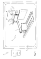
- the device 1 shown in Fig. 1 is used for computer-aided setting (Teaching) the trajectory of a handling system 2 a press brake 3 to a workpiece carried by a robot arm 4 of the handling system 2 (bent part) 5 supply and remove between the two bending tools 6 of the press brake 3.
- the device 1 comprises a screen 8 for displaying the to be corrected Movement section, the associated reference point, line or surface 7 and their degrees of freedom, a computer (computer) 9 to store the individual Movement sections and the associated reference points, lines or surfaces and for calculating the corrected trajectory and an operator (e.g. Mouse) 10 for moving the reference point, line or area 7 on the screen 8.
- a computer computer 9 to store the individual Movement sections and the associated reference points, lines or surfaces and for calculating the corrected trajectory
- an operator e.g. Mouse
- the degrees of freedom of the respective reference point, line or surface 7 are displayed permanently on the screen 8 as a dialog element 11 , which is arranged next to the reference point, line or surface 7 and connected thereto by a line 12 .
- the dialogue element 11 is a coordinate cross-like structure whose ends are marked with circles 13 which can be "touched” or activated by the user with the operating device 10.
- the circles 13 represent the respective two-dimensional movement possibilities that the user can perform by "touching" and moving a circle 13. A sequential execution of two of these two-dimensional movements can then result in a three-dimensional movement of the displayed handling system 2.
- the shifting functionality of the dialogue element 11 corresponds to a user's expectations, that is, no matter how distorted the bending scenery is displayed on the screen 8, it is always ensured that the workpiece 5 moves in the direction in which the user uses it of the dialog element 11 pulls.
- the dialogue element 11 has four circles 13 corresponding to the movements "turning (D) of the workpiece 5 about the wrist axis of the robot arm 4", “tilting (XY) the workpiece 5", “shifting (C) the workpiece 5 vertically and horizontally “and” shifting (Z) of the workpiece 5 forward and backward ".
- Fig. 1 the handling system 2 and the workpiece 5 to be threaded into the bending area of the press brake 3 are shown on the screen 8. If a machine operator standing in front of the press brake 3 guides the workpiece 5 in front of the press brake 3, then he always has the foremost edge of the workpiece 5 in view, because with this edge he could abut the press brake 3 in front of him. This leading edge is therefore assigned by the computer 9 the movement section "threading of the workpiece 5" as a reference line 7 for manual correction of the trajectory and forms the point of engagement of the dialogue element 11. The threading is usefully by tilting the workpiece 5 in front of the press brake 3, ie outside the two bending tools 6, introduced to the front edge of the workpiece or to the reference line 7.
- the dialog element 11 When tilting the workpiece 5 about its foremost edge, the position of this edge with respect to the bending tools 6 remains invariant. This is necessary because this edge of the workpiece 5 is pushed as the first between the bending tools 6 during threading. For this reason, the tilting of the workpiece 5 before the press brake 3 is also performed by the dialog element 11 around the front edge of the workpiece.
- the handling system 2 and the tilted during threading workpiece 5 are shown on the screen 8.
- the dialog element 11 In order to make the rotation distinguishable from a shift, the dialog element 11 also rotates in the case of the linear mouse movement for carrying out a rotational movement of the displayed handling system 2. In this way, the dialog element 11 also indicates the orientation of the workpiece 5 relative to the reference line 7.
- the threading process is completed when the workpiece 5 is located with its upcoming bending bending edge directly below the upper or above the lower bending tool 6, that is in the plane defined by both bending tools 6. This situation is shown in Fig. 3 on the screen 8.
Abstract
Description
Die vorliegende Erfindung betrifft ein Verfahren zum Festlegen der Bewegungsbahn eines ein Werkstück bewegenden Handlingsystems, insbesondere eines Handlingsystems einer Biegemaschine wie z.B. einer Abkantpresse, dessen Bewegungsbahn entsprechend den unterschiedlichen am Werkstück durchgeführten Prozessschritten mehrere Bewegungsabschnitte aufweist, wobei die Bewegungsbahn des Handlingsystems zunächst festgelegt und dann manuell korrigiert wird, sowie eine Vorrichtung zum Durchführen dieses Verfahrens. The present invention relates to a method for determining the trajectory a workpiece moving handling system, in particular one Handling system of a bending machine such. a press brake, whose Trajectory according to the different performed on the workpiece Process steps has a plurality of movement sections, wherein the Trajectory of the handling system initially set and then manually is corrected, and an apparatus for performing this method.
Ein derartiges Verfahren und eine entsprechende Vorrichtung sind beispielsweise durch JP 02077805 bekannt geworden.Such a method and a corresponding device are, for example become known by JP 02077805.
Das Teachen, also die Festlegung der Bewegungen von Handlingsystemen wie Robotern, ist immer noch eine mühsame Angelegenheit. Dabei sind Fahrpunkte durch deren Position und Ausrichtung des Handlingsystems festzulegen. Die Methoden der Festlegung von Fahrpunkten wurde ebenfalls in die Programmierung rechnergestützter Simulationen von Handlingsystemen übernommen. Diese heute üblichen Simulationen ermöglichen zwar eine Überprüfung der Fahrbewegungen, bevor diese an der Maschine abgearbeitet werden, erleichtern aber nur bedingt die Festlegung dieser Fahrpunkte.The teaching, so the determination of the movements of handling systems like Robots, is still a tedious task. These are driving points determined by their position and orientation of the handling system. The Methods of establishing driving points has also been included in the programming computer-aided simulations of handling systems. This today Although standard simulations make it possible to check the driving movements, before they are processed on the machine, but only partially facilitate the Defining these driving points.
Aus der eingangs genannten JP 02077805 ist ein Teach-Verfahren für einen Roboter bekannt, bei dem ein Teach-Punkt während der Simulation durch eine Roboteroperation korrigiert wird, während die Simulation auf der Basis eines Robotersteuerprogramms und von Teach-Daten des Roboters ausgeführt wird.From the aforementioned JP 02077805 is a teach method for a robot in which a teach point during the simulation by a Robot operation is corrected while the simulation is based on a Robot control program and teach data of the robot is executed.
Demgegenüber ist es die Aufgabe der vorliegenden Erfindung, ein Verfahren der eingangs genannten Art dahingehend weiterzubilden, dass der Bediener die Bewegungsbahn des Handlingsystems möglichst einfach und leicht korrigieren kann, sowie ein entsprechende Vorrichtung bereitzustellen.In contrast, it is the object of the present invention to provide a method of develop the aforementioned type such that the operator the Trajectory of the handling system can be corrected as simply and easily as possible, and to provide a corresponding device.
Diese Aufgabe wird erfindungsgemäß dadurch gelöst, dass bei der manuellen Korrektur ein Rechner jedem Bewegungsabschnitt eine in oder auf dem Werkstück liegende Bezugsstelle, -linie oder -fläche zuordnet, die in dem jeweiligen Bewegungsabschnitt die Bezugsgröße für eine manuelle Korrektur der Bewegungsbahn des Handlingsystems bildet.This object is achieved in that in the manual Correction of a computer every movement section one in or on the workpiece Assigning reference point, line or area that is in the respective Movement section is the reference for a manual correction of Movement path of the handling system forms.
Der wesentliche Vorteil der Erfindung besteht darin, dass am Werkstück für jeden Bewegungsabschnitt eine Bezugsgröße für die manuelle Korrektur der Bewegungsbahn festgelegt wird. Diese Bezugsgröße wird möglichst so gewählt, dass der Benutzer das Werkstück intuitiv im Raum bewegen kann, d.h., dass er die Art, wie er selbst als Maschinenbediener, d.h. vor einer Maschine stehend, das Werkstück führen würde, bei der manuellen Korrektur wiedererkennt. The essential advantage of the invention is that on the workpiece for each Movement section is a reference for the manual correction of Movement path is determined. This reference is chosen as possible that the user can intuitively move the workpiece in the room, that is, that he / she Way, as he himself as a machine operator, i. standing in front of a machine that Workpiece would recognize in the manual correction.
Vorzugsweise wird zumindest der zu korrigierende Bewegungsabschnitt mit seiner zugeordneten Bezugsstelle, -linie oder -fläche auf einem Bildschirm angezeigt und die manuelle Korrektur der Bewegungsbahn am Bildschirm graphisch durchgeführt.Preferably, at least the movement section to be corrected with his assigned reference point, line or area displayed on a screen and the manual correction of the trajectory on the screen graphically performed.
In einer besonders vorteilhaften Verfahrensvariante werden die Freiheitsgrade, die das Werkstück in der Bezugsstelle, -linie oder -fläche besitzt, auf dem Bildschirm angezeigt. In einer bevorzugten Weiterbildung dieser Verfahrensvariante werden die Freiheitsgrade der Bezugsstelle, -linie oder -fläche auf dem Bildschirm als Dialogelement anzeigt, das der Bezugsstelle, -linie oder -fläche optisch zugeordnet ist, insbesondere mit der Bezugsstelle, -linie oder -fläche durch eine Linie verbunden ist. Dabei können die angezeigten Freiheitsgrade der Bezugsstelle, -linie oder -fläche auf dem Bildschirm aktiviert werden, derart, dass eine Bewegung des aktivierten Freiheitsgrades zu einer entsprechenden Bewegung des Werkstücks auf dem Bildschirm führt. Das Dialogelement dient zur direkten Manipulation des Handlingsystems für das automatisierte Verarbeiten von Werkstücken mit dem Ziel, Fahrpunkte (Teach-Punkte) auf einfachste Weise graphisch durch den Benutzer festlegen zu können. Die Funktionalität des Dialogelementes legt fest, welche Aktionen mit diesem Dialogelement im jeweiligen Bewegungsabschnitt am Werkstück durchgeführt werden können. Das Handlingsystem ist ein Objekt, das sich im dreidimensionalen Raum bewegt. Die Fahrpunkte beziehen sich auf eine Saugerplatte des Handlingsystems bzw. auf das Werkstück selbst. Die heutigen praktikablen Eingabegeräte zur direkten graphischen Manipulation, wie zum Beispiel eine Maus, realisieren aber nur zweidimensionale lineare Bewegungen. Aus diesem Grund werden am Dialogelement die sechs Bewegungsrichtungen (Freiheitsgrade), die in einer Bezugsstelle, -linie oder -fläche möglich sind, also die Bewegung in die X-, Y- und Z-Richtung und die drei Drehungen um die X-, Y- und Z-Achse, in zweidimensionale Bewegungsrichtungen zerlegt und als Symbole angezeigt. Durch "Anfassen" und Verschieben eines Symbols kann die jeweilige zweidimensionale Bewegung des Werkstücks und durch sequentielle Durchführung zweier dieser zweidimensionalen Bewegungen eine dreidimensionale Bewegung durchgeführt werden. Die Verschiebungsfunktionalität des Dialogelements entspricht den Erwartungen eines Benutzers, d.h., ganz gleich, wie das Handlingsystem und das Werkstück auf dem Bildschirm dargestellt werden, es ist immer sichergestellt, dass das Werkstück sich in die Richtung bewegt, in die der Benutzer es mit Hilfe des Dialogelements zieht. Das Dialogelement bildet Handlungen des Maschinenbedieners z.B. an einer Biegemaschine auf einen metaphorischen Dialog ab.In a particularly advantageous variant of the method, the degrees of freedom are the workpiece has in the reference point, line or surface, on the screen displayed. In a preferred embodiment of this method variant, the Degrees of reference, line, or area on the screen as Displays a dialog item that optically maps to the datum, line, or face is in particular connected to the reference point, line or surface by a line is. The displayed degrees of freedom of the reference point, line or area be activated on the screen, such that a movement of the activated Degree of freedom to a corresponding movement of the workpiece on the Screen leads. The dialog element is used for direct manipulation of the Handling system for the automated processing of workpieces with the aim of Driving points (teach points) graphically in the simplest way by the user to be able to determine. The functionality of the dialog element determines which Actions with this dialog element in the respective movement section on the workpiece can be performed. The handling system is an object that is located in the three-dimensional space moves. The driving points refer to one Suction plate of the handling system or on the workpiece itself. Today practical input devices for direct graphic manipulation, such as a mouse, but only realize two-dimensional linear movements. For this The reason for the dialogue element is the six directions of movement (degrees of freedom), in a reference point, line or area are possible, so the movement in the X, Y and Z directions and the three rotations about the X, Y and Z axes, in split two-dimensional directions of movement and displayed as icons. By "Touching" and moving a symbol, the respective two-dimensional Movement of the workpiece and by sequentially performing two of these Two-dimensional movements performed a three-dimensional movement become. The shift functionality of the dialog element corresponds to the Expectations of a user, that is, no matter how the handling system and the Workpiece are displayed on the screen, it is always ensured that the workpiece moves in the direction in which the user uses the Pulls dialog element. The dialogue element forms actions of the Machine operator e.g. on a bending machine on a metaphorical dialogue from.
Beispielsweise kann im Falle einer Abkantpresse als Bezugsstelle, -linie oder -fläche beim Heranführen des Werkstücks an die Abkantpresse der Angriffpunkt des Handlingsystems am Werkstück, beim Einfädeln des Werkstücks zwischen die beiden Biegewerkzeuge der Abkantpresse die Vorderkante des Werkstücks und beim Kippen des Werkstücks innerhalb des Biegebereiches die zur Biegung anstehende Biegelinie des Werkstücks verwendet werden.For example, in the case of a press brake as a reference point, line or surface when approaching the workpiece to the press brake the point of attack of the Handling system on the workpiece, when threading the workpiece between the both bending tools of the press brake the leading edge of the workpiece and when tilting the workpiece within the bending area to the bend upcoming bending line of the workpiece can be used.
Die Erfindung betrifft auch eine Software, ein Computerprodukt oder Computerprogramm, das so ausgebildet ist, dass das oben beschriebene Verfahren auf einem Computer durchgeführt werden kann.The invention also relates to a software, a computer product or Computer program that is designed so that the method described above can be done on a computer.
Die Erfindung betrifft in einem weiteren Aspekt auch eine Vorrichtung zum rechnergestützten Durchführen des oben beschriebenen Verfahrens mit einem Bildschirm zum Anzeigen des zu korrigierenden Bewegungsabschnitts, der zugeordneten Bezugsstelle, -linie oder -fläche und deren Freiheitsgrade, mit einem Rechner zum Berechnen der korrigierten Bewegungsbahn sowie mit einer Bedieneinrichtung zum Bewegen der Bezugsstelle, -linie oder -fläche auf dem Bildschirm.In a further aspect, the invention also relates to a device for computer aided performing the method described above with a Screen for displaying the motion section to be corrected, the assigned reference point, line or surface and their degrees of freedom, with a Calculator for calculating the corrected trajectory and with a Operating device for moving the reference point, line or surface on the Screen.
Vorzugsweise sind die Freiheitsgrade der Bezugsstelle, -linie oder -fläche auf dem
Bildschirm dauerhaft als Dialogelement angezeigt, das beispielsweise durch eine
Linie mit der Bezugsstelle, -linie oder -fläche verbunden ist. Eine Verschiebung der
angezeigten Freiheitsgrade durch den Benutzer mittels der Bedieneinheit führt zu
einer entsprechenden Bewegung des Werkstücks auf dem Bildschirm.
Das Dialogelement dient zur direkten Manipulation des Handlingsystems für das
automatisierte Verarbeiten von Werkstücken mit dem Ziel, Fahrpunkte auf einfachste
Weise mit der Maus durch den Benutzer festlegen zu können. Preferably, the degrees of freedom of the reference location, line, or area on the screen are permanently displayed as a dialog element connected by, for example, a line to the reference location, line, or area. A displacement of the displayed degrees of freedom by the user by means of the operating unit leads to a corresponding movement of the workpiece on the screen.
The dialog element is used for the direct manipulation of the handling system for the automated processing of workpieces with the aim of being able to determine driving points in the simplest manner with the mouse by the user.
Weitere Vorteile der Erfindung ergeben sich aus der Beschreibung und der Zeichnung. Ebenso können die vorstehend genannten und die noch weiter aufgeführten Merkmale je für sich oder zu mehreren in beliebigen Kombinationen Verwendung finden. Die gezeigten und beschriebenen Ausführungsformen sind nicht als abschließende Aufzählung zu verstehen, sondern haben vielmehr beispielhaften Charakter für die Schilderung der Erfindung.Further advantages of the invention will become apparent from the description and the Drawing. Likewise, those mentioned above and even further listed features each for themselves or to several in any combination Find use. The embodiments shown and described are not as a conclusive enumeration, but rather have exemplary Character for the description of the invention.
Es zeigen:
- Fig. 1
- die erfindungsgemäße Vorrichtung mit einem Bildschirm, auf dem ein Handlingsystem einer Abkantpresse und ein in den Biegebereich der Abkantpresse einzufädelndes Werkstück dargestellt sind;
- Fig. 2
- die Vorrichtung der Fig. 1, wobei auf dem Bildschirm das Handlingsystem und das beim Einfädelvorgang verkippte Werkstück dargestellt sind und die Abkantpresse weggelassen ist; und
- Fig. 3
- die Vorrichtung der Fig. 1, wobei auf dem Bildschirm das Handlingsystem und das in den Biegebereich der Abkantpresse eingefädelte Werkstück dargestellt sind.
- Fig. 1
- the device according to the invention with a screen on which a handling system of a press brake and a workpiece to be threaded into the bending region of the press brake are shown;
- Fig. 2
- the apparatus of Figure 1, wherein on the screen, the handling system and the workpiece tilted during the threading are shown and the press brake is omitted ..; and
- Fig. 3
- the apparatus of Fig. 1, wherein on the screen, the handling system and the threaded in the bending region of the press brake workpiece are shown.
Die in Fig. 1 gezeigte Vorrichtung 1 dient zum rechnergestützten Festlegen
(Teachen) der Bewegungsbahn eines Handlingsystems 2 einer Abkantpresse 3, um
ein von einem Robotorarm 4 des Handlingsystem 2 getragenes Werkstück (Biegeteil)
5 zwischen die beiden Biegewerkzeuge 6 der Abkantpresse 3 zu- und abzuführen.The
Eine, z.B. mittels Simulation, zunächst festgelegte Bewegungsbahn des
Handlingsystems 2 kann mit Hilfe der Vorrichtung 1 manuell korrigiert werden. Bei
dieser Korrektur werden die folgenden Schritte durchgeführt:
Die Vorrichtung 1 umfasst einen Bildschirm 8 zum Anzeigen des zu korrigierenden
Bewegungsabschnitts, der zugeordneten Bezugsstelle, -linie oder -fläche 7 und
deren Freiheitsgrade, einen Rechner (Computer) 9 zum Speichern der einzelnen
Bewegungsabschnitte und der zugeordneten Bezugsstellen, -linien oder flächen und
zum Berechnen der korrigierten Bewegungsbahn sowie eine Bedieneinrichtung (z.B.
Maus) 10 zum Bewegen der Bezugsstelle, -linie oder -fläche 7 auf dem Bildschirm 8. The
Die Freiheitsgrade der jeweiligen Bezugsstelle, -linie oder -fläche 7 werden auf dem
Bildschirm 8 dauerhaft als Dialogelement 11 angezeigt, das neben der Bezugsstelle,
-linie oder -fläche 7 angeordnet und mit dieser durch eine Linie 12 verbunden ist. Das
Dialogelement 11 ist ein koordinatenkreuzähnliches Gebilde, dessen Enden mit
Kreisen 13 markiert sind, die durch den Benutzer mit der Bedieneinrichtung 10
"angefasst" bzw. aktiviert werden können. Die Kreise 13 stehen für die jeweiligen
zweidimensionalen Bewegungsmöglichkeiten, die der Benutzer durch "Anfassen"
und Verschieben eines Kreises 13 durchführen kann. Eine sequentielle Durchführung
zweier dieser zweidimensionalen Bewegungen kann dann eine dreidimensionale
Bewegung des angezeigten Handlingsystems 2 ergeben. Die
Verschiebungsfunktionalität des Dialogelements 11 entspricht den Erwartungen
eines Benutzers, d.h., ganz gleich, wie verdreht die Biegeszenerie auch auf dem
Bildschirm 8 dargestellt wird, es ist immer sichergestellt, dass das Werkstück 5 sich
in die Richtung bewegt, in die der Benutzer es mit Hilfe des Dialogelements 11 zieht.
Im gezeigten Ausführungsbeispiel hat das Dialogelement 11 vier Kreise 13
entsprechend den Bewegungen "Drehen (D) des Werkstückes 5 um die
Handgelenkachse des Roboterarms 4", "Kippen (XY) des Werkstückes 5",
"Verschieben (C) des Werkstückes 5 vertikal und horizontal" und "Verschieben (Z)
des Werkstücks 5 vorwärts und zurück".The degrees of freedom of the respective reference point, line or
In Fig. 1 sind auf dem Bildschirm 8 das Handlingsystem 2 und das in den
Biegebereich der Abkantpresse 3 einzufädelnde Werkstück 5 dargestellt. Führt ein
vor der Abkantpresse 3 stehender Maschinenbediener das Werkstück 5 vor der
Abkantpresse 3, so hat er immer die vorderste Kante des Werkstücks 5 im Blick,
denn mit dieser Kante könnte er an der vor ihm liegenden Abkantpresse 3 anstoßen.
Diese vorderste Kante wird daher vom Rechner 9 dem Bewegungsabschnitt
"Einfädeln des Werkstücks 5" als Bezugslinie 7 für die manuelle Korrektur der
Bewegungsbahn zugeordnet und bildet den Angriffspunkt des Dialogelements 11.
Der Einfädelvorgang wird sinnvollerweise durch Kippen des Werkstücks 5 vor der
Abkantpresse 3, also außerhalb der beiden Biegewerkzeuge 6, um die vordere
Werkstückkante bzw. um die Bezugslinie 7 eingeleitet. Beim Kippen des Werkstücks
5 um seine vorderste Kante bleibt die Position dieser Kante gegenüber den
Biegewerkzeugen 6 invariant. Dies ist notwendig, da diese Kante des Werkstücks 5
beim Einfädeln als erste zwischen die Biegewerkzeuge 6 geschoben wird. Aus
diesem Grund wird das Kippen des Werkstücks 5 vor der Abkantpresse 3 auch vom
Dialogelement 11 um die vordere Werkstückkante durchgeführt. In Fig. 2 sind auf
dem Bildschirm 8 das Handlingsystem 2 und das beim Einfädeln verkippte Werkstück
5 dargestellt. Um die Drehung von einer Verschiebung unterscheidbar zu machen,
dreht sich das Dialogelement 11 bei der linearen Mausbewegung für die
Durchführung einer Drehbewegung des angezeigten Handlingsystems 2 ebenfalls
mit. Auf diese Weise zeigt das Dialogelement 11 auch die Orientierung des
Werkstücks 5 bezogen auf die Bezugslinie 7 an. Der Einfädelvorgang ist beendet,
wenn das Werkstück 5 mit seiner zur Biegung anstehenden Biegekante direkt unter
dem oberen bzw. über dem unteren Biegewerkzeug 6 liegt, also in der durch beide
Biegewerkzeuge 6 definierten Ebene liegt. Diese Situation ist in Fig. 3 auf dem
Bildschirm 8 dargestellt.In Fig. 1 , the
Für noch erforderliche Kippbewegungen des eingefädelten Werkstücks 5 würde der
vor der Abkantpresse 3 stehende Maschinenbediener das Werkstücks 5 um die
gedachte Schnittlinie des Werkstücks 5 mit der durch beide Biegewerkzeuge 6
definierten Ebene drehen. Diese Schnittlinie wird daher vom Rechner 9 dem
Bewegungsabschnitt "Verkippen des Werkstücks 5 zwischen den Biegewerkzeugen
6" als Bezugslinie 7 für die manuelle Korrektur der Bewegungsbahn zugeordnet und
bildet den Angriffspunkt des Dialogelements 11. So wird verhindert, dass das
Werkstück 5 bei einer Kippbewegung mit den Biegewerkzeugen 6 kollidiert.For still necessary tilting movements of the threaded
Claims (14)
Priority Applications (1)
| Application Number | Priority Date | Filing Date | Title |
|---|---|---|---|
| EP20030077737 EP1510893B1 (en) | 2003-09-01 | 2003-09-01 | Process and device for the determination of the movement path in a handling system |
Applications Claiming Priority (1)
| Application Number | Priority Date | Filing Date | Title |
|---|---|---|---|
| EP20030077737 EP1510893B1 (en) | 2003-09-01 | 2003-09-01 | Process and device for the determination of the movement path in a handling system |
Publications (2)
| Publication Number | Publication Date |
|---|---|
| EP1510893A1 true EP1510893A1 (en) | 2005-03-02 |
| EP1510893B1 EP1510893B1 (en) | 2014-11-05 |
Family
ID=34089677
Family Applications (1)
| Application Number | Title | Priority Date | Filing Date |
|---|---|---|---|
| EP20030077737 Expired - Lifetime EP1510893B1 (en) | 2003-09-01 | 2003-09-01 | Process and device for the determination of the movement path in a handling system |
Country Status (1)
| Country | Link |
|---|---|
| EP (1) | EP1510893B1 (en) |
Cited By (3)
| Publication number | Priority date | Publication date | Assignee | Title |
|---|---|---|---|---|
| EP2124117A1 (en) | 2008-05-21 | 2009-11-25 | Siemens Aktiengesellschaft | Operating device for operating a machine tool |
| DE102015105687A1 (en) * | 2014-10-14 | 2016-04-14 | Janome Sewing Machine Co., Ltd. | robot |
| DE102018009025B4 (en) | 2017-11-24 | 2023-10-12 | Fanuc Corporation | Robot control device for setting a motion coordinate system |
Citations (3)
| Publication number | Priority date | Publication date | Assignee | Title |
|---|---|---|---|---|
| US4831548A (en) * | 1985-10-23 | 1989-05-16 | Hitachi, Ltd. | Teaching apparatus for robot |
| EP0455817A1 (en) * | 1989-11-20 | 1991-11-13 | Fanuc Ltd. | Three-dimensional cursor and off-line programming system using the same |
| EP0792726A1 (en) * | 1995-09-18 | 1997-09-03 | Fanuc Ltd. | Teach pendant |
-
2003
- 2003-09-01 EP EP20030077737 patent/EP1510893B1/en not_active Expired - Lifetime
Patent Citations (3)
| Publication number | Priority date | Publication date | Assignee | Title |
|---|---|---|---|---|
| US4831548A (en) * | 1985-10-23 | 1989-05-16 | Hitachi, Ltd. | Teaching apparatus for robot |
| EP0455817A1 (en) * | 1989-11-20 | 1991-11-13 | Fanuc Ltd. | Three-dimensional cursor and off-line programming system using the same |
| EP0792726A1 (en) * | 1995-09-18 | 1997-09-03 | Fanuc Ltd. | Teach pendant |
Cited By (5)
| Publication number | Priority date | Publication date | Assignee | Title |
|---|---|---|---|---|
| EP2124117A1 (en) | 2008-05-21 | 2009-11-25 | Siemens Aktiengesellschaft | Operating device for operating a machine tool |
| DE102015105687A1 (en) * | 2014-10-14 | 2016-04-14 | Janome Sewing Machine Co., Ltd. | robot |
| DE102015105687B4 (en) * | 2014-10-14 | 2016-05-12 | Janome Sewing Machine Co., Ltd. | robot |
| US9718186B2 (en) | 2014-10-14 | 2017-08-01 | Janome Sewing Machine Co., Ltd. | Robot |
| DE102018009025B4 (en) | 2017-11-24 | 2023-10-12 | Fanuc Corporation | Robot control device for setting a motion coordinate system |
Also Published As
| Publication number | Publication date |
|---|---|
| EP1510893B1 (en) | 2014-11-05 |
Similar Documents
| Publication | Publication Date | Title |
|---|---|---|
| EP1447770B1 (en) | Method and apparatus for visualization of computer-based information | |
| EP2285537B1 (en) | Device and method for the computer-assisted generation of a manipulator track | |
| DE60025683T2 (en) | Graphic display device for a robot system | |
| DE102010036499B4 (en) | Tool vector display device for a machine tool with a rotation axis | |
| DE102015012961B4 (en) | robotic system | |
| DE102015105687B4 (en) | robot | |
| DE102018009023B4 (en) | Teaching device for carrying out robot teaching processes and teaching methods | |
| DE102018009025B4 (en) | Robot control device for setting a motion coordinate system | |
| WO2017060539A1 (en) | Robot system | |
| DE102015107436B4 (en) | Trainable path control | |
| DE102013106076B4 (en) | Tool path display device for displaying the tool vector of a machine tool | |
| DE102013008755B4 (en) | Offline programming system | |
| DE102010039540C5 (en) | Manual control device for moving a robot arm manually | |
| EP0249171B1 (en) | Programme control method for the automated coating of work pieces, especially for an industrial robot | |
| DE102019117877B4 (en) | ROBOT PROGRAM GENERATION DEVICE | |
| EP3418839B1 (en) | Method for monitoring an automation assembly | |
| EP1510893B1 (en) | Process and device for the determination of the movement path in a handling system | |
| EP1700175A1 (en) | Device and method for programming an industrial robot | |
| DE102019006748A1 (en) | ROBOT TEACHING DEVICE, ROBOT TEACHING METHOD AND METHOD FOR STORING AN OPERATING MANUAL | |
| DE102018128175A1 (en) | Method and device for determining displacements of a tool center | |
| DE102018002733A1 (en) | Information processing apparatus | |
| EP2118618A1 (en) | Method for determining measuring points | |
| DE102019130008B4 (en) | ACTIVITY PROGRAM CREATION INSTALLATION | |
| DE102004032996A1 (en) | Robot programming method for robot of data processing system involves functional unit whereby virtual work area is generated and course of motion for robot in start position and end position is specified | |
| DE102019211270B3 (en) | Controlling a Robot |
Legal Events
| Date | Code | Title | Description |
|---|---|---|---|
| PUAI | Public reference made under article 153(3) epc to a published international application that has entered the european phase |
Free format text: ORIGINAL CODE: 0009012 |
|
| AK | Designated contracting states |
Kind code of ref document: A1 Designated state(s): AT BE BG CH CY CZ DE DK EE ES FI FR GB GR HU IE IT LI LU MC NL PT RO SE SI SK TR |
|
| AX | Request for extension of the european patent |
Extension state: AL LT LV MK |
|
| 17P | Request for examination filed |
Effective date: 20050806 |
|
| AKX | Designation fees paid |
Designated state(s): AT BE BG CH CY CZ DE DK EE ES FI FR GB GR HU IE IT LI LU MC NL PT RO SE SI SK TR |
|
| 17Q | First examination report despatched |
Effective date: 20070824 |
|
| GRAP | Despatch of communication of intention to grant a patent |
Free format text: ORIGINAL CODE: EPIDOSNIGR1 |
|
| INTG | Intention to grant announced |
Effective date: 20140528 |
|
| GRAS | Grant fee paid |
Free format text: ORIGINAL CODE: EPIDOSNIGR3 |
|
| GRAA | (expected) grant |
Free format text: ORIGINAL CODE: 0009210 |
|
| AK | Designated contracting states |
Kind code of ref document: B1 Designated state(s): AT BE BG CH CY CZ DE DK EE ES FI FR GB GR HU IE IT LI LU MC NL PT RO SE SI SK TR |
|
| REG | Reference to a national code |
Ref country code: GB Ref legal event code: FG4D Free format text: NOT ENGLISH |
|
| REG | Reference to a national code |
Ref country code: CH Ref legal event code: EP |
|
| REG | Reference to a national code |
Ref country code: AT Ref legal event code: REF Ref document number: 694932 Country of ref document: AT Kind code of ref document: T Effective date: 20141115 |
|
| REG | Reference to a national code |
Ref country code: IE Ref legal event code: FG4D Free format text: LANGUAGE OF EP DOCUMENT: GERMAN |
|
| REG | Reference to a national code |
Ref country code: DE Ref legal event code: R096 Ref document number: 50315152 Country of ref document: DE Effective date: 20141211 |
|
| REG | Reference to a national code |
Ref country code: NL Ref legal event code: VDEP Effective date: 20141105 |
|
| PG25 | Lapsed in a contracting state [announced via postgrant information from national office to epo] |
Ref country code: NL Free format text: LAPSE BECAUSE OF FAILURE TO SUBMIT A TRANSLATION OF THE DESCRIPTION OR TO PAY THE FEE WITHIN THE PRESCRIBED TIME-LIMIT Effective date: 20141105 Ref country code: ES Free format text: LAPSE BECAUSE OF FAILURE TO SUBMIT A TRANSLATION OF THE DESCRIPTION OR TO PAY THE FEE WITHIN THE PRESCRIBED TIME-LIMIT Effective date: 20141105 Ref country code: PT Free format text: LAPSE BECAUSE OF FAILURE TO SUBMIT A TRANSLATION OF THE DESCRIPTION OR TO PAY THE FEE WITHIN THE PRESCRIBED TIME-LIMIT Effective date: 20150305 Ref country code: FI Free format text: LAPSE BECAUSE OF FAILURE TO SUBMIT A TRANSLATION OF THE DESCRIPTION OR TO PAY THE FEE WITHIN THE PRESCRIBED TIME-LIMIT Effective date: 20141105 |
|
| PG25 | Lapsed in a contracting state [announced via postgrant information from national office to epo] |
Ref country code: GR Free format text: LAPSE BECAUSE OF FAILURE TO SUBMIT A TRANSLATION OF THE DESCRIPTION OR TO PAY THE FEE WITHIN THE PRESCRIBED TIME-LIMIT Effective date: 20150206 Ref country code: CY Free format text: LAPSE BECAUSE OF FAILURE TO SUBMIT A TRANSLATION OF THE DESCRIPTION OR TO PAY THE FEE WITHIN THE PRESCRIBED TIME-LIMIT Effective date: 20141105 Ref country code: SE Free format text: LAPSE BECAUSE OF FAILURE TO SUBMIT A TRANSLATION OF THE DESCRIPTION OR TO PAY THE FEE WITHIN THE PRESCRIBED TIME-LIMIT Effective date: 20141105 |
|
| PG25 | Lapsed in a contracting state [announced via postgrant information from national office to epo] |
Ref country code: RO Free format text: LAPSE BECAUSE OF FAILURE TO SUBMIT A TRANSLATION OF THE DESCRIPTION OR TO PAY THE FEE WITHIN THE PRESCRIBED TIME-LIMIT Effective date: 20141105 Ref country code: EE Free format text: LAPSE BECAUSE OF FAILURE TO SUBMIT A TRANSLATION OF THE DESCRIPTION OR TO PAY THE FEE WITHIN THE PRESCRIBED TIME-LIMIT Effective date: 20141105 Ref country code: CZ Free format text: LAPSE BECAUSE OF FAILURE TO SUBMIT A TRANSLATION OF THE DESCRIPTION OR TO PAY THE FEE WITHIN THE PRESCRIBED TIME-LIMIT Effective date: 20141105 Ref country code: DK Free format text: LAPSE BECAUSE OF FAILURE TO SUBMIT A TRANSLATION OF THE DESCRIPTION OR TO PAY THE FEE WITHIN THE PRESCRIBED TIME-LIMIT Effective date: 20141105 Ref country code: SK Free format text: LAPSE BECAUSE OF FAILURE TO SUBMIT A TRANSLATION OF THE DESCRIPTION OR TO PAY THE FEE WITHIN THE PRESCRIBED TIME-LIMIT Effective date: 20141105 |
|
| REG | Reference to a national code |
Ref country code: DE Ref legal event code: R097 Ref document number: 50315152 Country of ref document: DE |
|
| PLBE | No opposition filed within time limit |
Free format text: ORIGINAL CODE: 0009261 |
|
| STAA | Information on the status of an ep patent application or granted ep patent |
Free format text: STATUS: NO OPPOSITION FILED WITHIN TIME LIMIT |
|
| REG | Reference to a national code |
Ref country code: FR Ref legal event code: PLFP Year of fee payment: 13 |
|
| 26N | No opposition filed |
Effective date: 20150806 |
|
| PG25 | Lapsed in a contracting state [announced via postgrant information from national office to epo] |
Ref country code: SI Free format text: LAPSE BECAUSE OF FAILURE TO SUBMIT A TRANSLATION OF THE DESCRIPTION OR TO PAY THE FEE WITHIN THE PRESCRIBED TIME-LIMIT Effective date: 20141105 |
|
| PG25 | Lapsed in a contracting state [announced via postgrant information from national office to epo] |
Ref country code: MC Free format text: LAPSE BECAUSE OF FAILURE TO SUBMIT A TRANSLATION OF THE DESCRIPTION OR TO PAY THE FEE WITHIN THE PRESCRIBED TIME-LIMIT Effective date: 20141105 Ref country code: LU Free format text: LAPSE BECAUSE OF FAILURE TO SUBMIT A TRANSLATION OF THE DESCRIPTION OR TO PAY THE FEE WITHIN THE PRESCRIBED TIME-LIMIT Effective date: 20150901 |
|
| REG | Reference to a national code |
Ref country code: CH Ref legal event code: PL |
|
| REG | Reference to a national code |
Ref country code: IE Ref legal event code: MM4A |
|
| PG25 | Lapsed in a contracting state [announced via postgrant information from national office to epo] |
Ref country code: IE Free format text: LAPSE BECAUSE OF NON-PAYMENT OF DUE FEES Effective date: 20150901 Ref country code: LI Free format text: LAPSE BECAUSE OF NON-PAYMENT OF DUE FEES Effective date: 20150930 Ref country code: CH Free format text: LAPSE BECAUSE OF NON-PAYMENT OF DUE FEES Effective date: 20150930 |
|
| REG | Reference to a national code |
Ref country code: FR Ref legal event code: PLFP Year of fee payment: 14 |
|
| REG | Reference to a national code |
Ref country code: AT Ref legal event code: MM01 Ref document number: 694932 Country of ref document: AT Kind code of ref document: T Effective date: 20150901 |
|
| PG25 | Lapsed in a contracting state [announced via postgrant information from national office to epo] |
Ref country code: AT Free format text: LAPSE BECAUSE OF NON-PAYMENT OF DUE FEES Effective date: 20150901 |
|
| PG25 | Lapsed in a contracting state [announced via postgrant information from national office to epo] |
Ref country code: HU Free format text: LAPSE BECAUSE OF FAILURE TO SUBMIT A TRANSLATION OF THE DESCRIPTION OR TO PAY THE FEE WITHIN THE PRESCRIBED TIME-LIMIT; INVALID AB INITIO Effective date: 20030901 Ref country code: BG Free format text: LAPSE BECAUSE OF FAILURE TO SUBMIT A TRANSLATION OF THE DESCRIPTION OR TO PAY THE FEE WITHIN THE PRESCRIBED TIME-LIMIT Effective date: 20141105 |
|
| PG25 | Lapsed in a contracting state [announced via postgrant information from national office to epo] |
Ref country code: BE Free format text: LAPSE BECAUSE OF NON-PAYMENT OF DUE FEES Effective date: 20150930 |
|
| PG25 | Lapsed in a contracting state [announced via postgrant information from national office to epo] |
Ref country code: TR Free format text: LAPSE BECAUSE OF FAILURE TO SUBMIT A TRANSLATION OF THE DESCRIPTION OR TO PAY THE FEE WITHIN THE PRESCRIBED TIME-LIMIT Effective date: 20141105 |
|
| REG | Reference to a national code |
Ref country code: FR Ref legal event code: PLFP Year of fee payment: 15 |
|
| REG | Reference to a national code |
Ref country code: FR Ref legal event code: PLFP Year of fee payment: 16 |
|
| PGFP | Annual fee paid to national office [announced via postgrant information from national office to epo] |
Ref country code: FR Payment date: 20210921 Year of fee payment: 19 Ref country code: IT Payment date: 20210922 Year of fee payment: 19 |
|
| PGFP | Annual fee paid to national office [announced via postgrant information from national office to epo] |
Ref country code: GB Payment date: 20210920 Year of fee payment: 19 Ref country code: DE Payment date: 20210920 Year of fee payment: 19 |
|
| REG | Reference to a national code |
Ref country code: DE Ref legal event code: R119 Ref document number: 50315152 Country of ref document: DE |
|
| GBPC | Gb: european patent ceased through non-payment of renewal fee |
Effective date: 20220901 |
|
| PG25 | Lapsed in a contracting state [announced via postgrant information from national office to epo] |
Ref country code: FR Free format text: LAPSE BECAUSE OF NON-PAYMENT OF DUE FEES Effective date: 20220930 Ref country code: DE Free format text: LAPSE BECAUSE OF NON-PAYMENT OF DUE FEES Effective date: 20230401 |
|
| PG25 | Lapsed in a contracting state [announced via postgrant information from national office to epo] |
Ref country code: IT Free format text: LAPSE BECAUSE OF NON-PAYMENT OF DUE FEES Effective date: 20220901 Ref country code: GB Free format text: LAPSE BECAUSE OF NON-PAYMENT OF DUE FEES Effective date: 20220901 |