EP1505513A2 - Graphical calculator - Google Patents
Graphical calculator Download PDFInfo
- Publication number
- EP1505513A2 EP1505513A2 EP04254474A EP04254474A EP1505513A2 EP 1505513 A2 EP1505513 A2 EP 1505513A2 EP 04254474 A EP04254474 A EP 04254474A EP 04254474 A EP04254474 A EP 04254474A EP 1505513 A2 EP1505513 A2 EP 1505513A2
- Authority
- EP
- European Patent Office
- Prior art keywords
- calculator
- user
- key
- input
- graphical
- Prior art date
- Legal status (The legal status is an assumption and is not a legal conclusion. Google has not performed a legal analysis and makes no representation as to the accuracy of the status listed.)
- Withdrawn
Links
Images


Classifications
-
- G—PHYSICS
- G06—COMPUTING; CALCULATING OR COUNTING
- G06F—ELECTRIC DIGITAL DATA PROCESSING
- G06F15/00—Digital computers in general; Data processing equipment in general
- G06F15/02—Digital computers in general; Data processing equipment in general manually operated with input through keyboard and computation using a built-in program, e.g. pocket calculators
- G06F15/025—Digital computers in general; Data processing equipment in general manually operated with input through keyboard and computation using a built-in program, e.g. pocket calculators adapted to a specific application
Definitions
- the present invention relates to a hand-held calculator, preferably a graphical calculator and graphical calculator package.
- a hand-held calculator is an important and useful device. Similar to a computer, the hand-held calculator has a processor, a memory, a display, and an input device; however, there are important distinguishing differences between the hand-held calculator and the computer.
- the hand-held calculator is a specialized device and not a general purpose device, as is true of a computer. Because of this specialization, typically the handheld calculator costs less, has a longer useful lifespan, and is more reliable and more portable than the computer.
- a hand-held calculator typically executes a single program and less frequently supports execution of user-created programs.
- a hand-held calculator supports addition, subtraction, multiplication, and division of numbers, either integer-based or decimal-based, entered by a user and displays the results on a built-in display.
- a graphical calculator is a further specialized version of a hand-held calculator having a display which is typically larger than a regular hand-held calculator display in order to enable graph output.
- graphical calculator displays are liquid crystal displays for more accurate representation and enhanced readability of a graph output.
- a graphical calculator is able to display a graph of a specific expression, e.g. a sine wave representing a sinusoidal function, entered by a user.
- a specific expression e.g. a sine wave representing a sinusoidal function
- graphical capabilities on hand-held calculators are only available as part of expensive and complex, "high end" scientific calculators. These graphical calculators are more expensive than other calculators, typically costing hundreds of Euros/Dollars. These graphical calculators are more complicated to operate than other calculators because of the large amount of functionality incorporated therein.
- the increased functionality has required a corresponding increase in the number of keys required for manipulating and using the calculator.
- currently available graphical calculators have approximately fifty (50) keys including two (2) shift or modifier keys for a user to manipulate, e.g. a Texas Instruments (TI) 83 plus calculator has 51 keys and 2 shift keys that can be used concurrently, allowing up to 4 functions per key and a Hewlett-Packard (HP) 48G+/GX calculator has keys and 3 shift keys allowing up to 6 functions per key.
- TI Texas Instruments
- HP Hewlett-Packard
- a user must contend with different modes of operation of the current graphical calculator. Different modes of operation, accessible via specific keys and/or key sequences, must be utilized in order to access specific calculator functionality, e.g. a graphical calculator may include a decimal mode, a binary mode, a hexadecimal mode, a finance mode, a statistics mode, and a graph mode.
- expression input requires increasingly complicated key manipulations and combinations.
- a mode specifying combination may include manipulation of a graph key to instruct the calculator to graph the following expression entry.
- the expression entry combination may include manipulation of multiple keys to input the expression to be graphed and the completion combination includes manipulation of a key, e.g. an enter key, to instruct the calculator to perform the preceding operations, i.e. graph the entered expression.
- the user manual for a currently available hand-held graphical calculator has dramatically increased in size in order to fully explain the use of the calculator.
- the above-cited TI-83 plus calculator manual includes 269 pages and the HP 48G+/GX calculator manual includes 506 pages. These are very long documents which are typically not read by users. Further, users are likely to be deterred from reading the manual because of the imposing size of the manual.
- Graphical calculators are very, popular and effective educational aides. School students using graphical calculators can easily visualize complex functions; however, the complexity and cost of currently available graphical calculators deters many students and schools from making a purchase. Purchasers are dissuaded by the size of the manual, multiple modes of operation, and the number of keys and key combinations required for inputting expressions.
- the present invention seeks to provide an improved calculator, preferably an improved graphical calculator; an improved graphical calculator package; and/or an improved graphical calculator and graphical calculator package.
- a hand-held graphical calculator has a display and an input area.
- the input area includes a maximum of 30 keys and an input device.
- An improved hand-held graphical calculator package includes a hand-held graphical calculator for graphically displaying a user-entered expression and a user manual.
- the user manual is a single sheet of instructions fully describing operation of the graphical calculator.
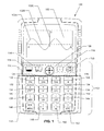
- Figure 1 is a front face view of a graphical calculator 100 according to an embodiment of the present invention.
- Calculator 100 includes a display 102 and a primarily key-based input area 104 set in a front face 106.
- front face 106 is shown as a rounded rectangle, it is to be understood that the front face may be manufactured to be any of a number of different shapes.
- input mechanisms are described below, it is to be understood that variations in the number, type, and configuration of input mechanisms may be found in different embodiments of the present invention.
- Display 102 is a rectangular liquid crystal display (LCD) which is 96 pixels wide and 64 pixels in height. As shown in figure 1, display 102 displays a sine wave 102A on a graph having an X axis 102B and a Y axis 102C.
- Input area 104 includes four keys and one directional input device 108 in a row 110 and 16 keys arranged in a four by four grid 112.
- Directional input device 108 is used to navigate menus and perform information input, recall, and editing.
- Directional input device 108 may be manipulated by the user to input at least four directions, i.e. up, down, left, and right to calculator 100.
- the four keys in row 110 are shift key 114, open parenthesis key 116, close parenthesis key 118, and power key 120.
- Shift key 114 is used to access a second set of functions, i.e. secondary functions, assigned to the remaining keys on calculator 100. For example, user activating power key 120 turns on calculator 100; however, activation of power key 120 subsequent to activation of shift key 114 turns off the calculator. In a similar fashion, each of the remaining keys of calculator 100 has an assigned secondary function.
- Open parenthesis key 116 inputs a beginning parenthesis in a user-entered expression.
- the secondary function of open parenthesis key 116 is to input a command causing calculator 100 to split a graphical output on display 102 such that one half of the display is a graph and the other half is numerical information related to the graph displayed.
- Close parenthesis key 118 inputs an ending parenthesis in a user-entered expression.
- the secondary function of close parenthesis key 118 is to input a T variable in a user-entered expression.
- Power key 120 turns on calculator 100 and, as described above, the secondary function of power key 120 is to turn off calculator 100. Additionally, power key 120 operates as a clear key after calculator 100 is turned on, i.e. the power key may be used to clear the displayed expression on display 102. Manipulation of shift key 114 followed by right arrow of directional input device 108 deletes input characters to the right of the current input position and manipulation of shift key 114 followed by left arrow of directional input device 108 deletes input characters to the left of the current input position.
- Row 1, column 1 key 122 i.e. the seven key, inputs a seven (7) value in a user-entered expression and has a secondary function of inputting a sin function in a user-entered expression.
- Row 1, column 2 key 124 i.e. the eight key, inputs an eight (8) value in a user-entered expression and has a secondary function of inputting a cos function in a user-entered expression.
- Row 1, column 3 key 126, i.e. the nine key, inputs a nine (9) value in a user-entered expression and has a secondary function of inputting a tan function in a user-entered expression.
- Row 1, column 4 key 128, i.e. the division key inputs a division (/) function in a user-entered expression and has a secondary function of inputting a theta ( ⁇ ) variable in a user-entered expression.
- Row 2, column 1 key 130 i.e. the four key, inputs a four (4) value in a user-entered expression and has a secondary function of inputting a square root function in a user-entered expression.
- Row 2, column 2 key 132 i.e. the five key, inputs a five-(5) value in a user entered expression and has a secondary function of inputting a squared function, i.e. raising a value to the second power, in a user-entered expression.
- Row 2, column 3 key 134 i.e. the six key, inputs a six (6) value in a user-entered expression and has a secondary function of inputting a value raised to the power of a subsequently entered value function, i.e.
- Row 2 key 136 i.e. the multiplication key, inputs a multiplication (*) function in a user-entered expression and has a secondary function of inputting an X variable in a user-entered expression.
- Row 3, column 1 key 138 i.e. the one key, inputs a one (i) value in a user-entered expression and has a secondary function of inputting an absolute value function in a user-entered expression.
- Row 3, column 2 key 140 i.e. the 2 key, inputs a two (2) value in a user-entered expression and has a secondary function of inputting a natural logarithm function in a user-entered expression.
- Row 3, column 3 key 142 i.e. the three key, inputs a three (3) value in a user-entered expression and has a secondary function of in putting eight logarithm function in a user-entered expression.
- Row 3, column 4 key 144 i.e. the minus key, inputs a subtraction (-) function in a user-entered expression and has a secondary function of inputting a NOT function in a user-entered expression.
- Row 4, column 1 key 146 i.e. the execute key, inputs an execute command to calculator 100 and has a secondary function of inputting a menu command to the calculator.
- Row 4, column 2 key 148 i.e. the zero key, inputs a zero (0) value in a user-entered expression and has a secondary function of inputting an e value in a user-entered expression.
- Row 4, column 3 key 150 i.e. the dot key, inputs a decimal point in a value entry and has a secondary function of in putting a pi constant value in a user-entered expression.
- Row 4, column 4 key 152 of i.e.
- the plus key inputs an addition (+) function in a user-entered expression and has a secondary function of in putting a times ten to the power of a subsequently entered value, i.e. "*10 ⁇ Y", in a user-entered expression.
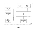
- Figure 2 is a block diagram illustrating an exemplary calculator 100 upon which an embodiment of the invention may be implemented.
- Calculator 100 includes a bus 202 or other communication mechanism for communicating information, and a processor 204 coupled with the bus 202 processing information.
- processor 204 is a 16 bit processor.
- Calculator 100 also includes a main memory 206, such as a random access memory (RAM) or other dynamic storage device, coupled to the bus 202 for storing data and expressions according to an embodiment of the present invention and instructions to be executed by processor 204.
- Main memory 206 also may be used for storing temporary variables or other intermediate information during execution of instructions to be executed by processor 204.
- main memory 206 is an 8 Kilobyte RAM.
- the components of calculator 100 may be combined onto a single integrated circuit, e.g. processor 204 and main memory 206 may be combined on a single "system on a chip.”
- Calculator 100 further includes a read only memory (ROM) 208 or other static storage device coupled to the bus 202 for storing static information and instructions for the processor 204.
- ROM 208 is a 128 Kilobyte ROM.
- Calculator 100 may be coupled via the bus 202 to a display 212, such as the above-described 96 * 64 pixel LCD, for displaying an interface to a user.
- An input area 104 is coupled to the bus 202 for communicating information, e.g. user-entered expressions and values, and command inputs to the processor 204.
- An input device 108 is part of input area 104 and communicates direction information and command selections to processor 204 and controls cursor movement on the display 212.
- This input device typically has two degrees of freedom in two axes, a first axis (e.g., x) and a second axis (e.g., y) allowing the device to specify positions in a plane.
- calculator 100 such as the depicted calculator of Figure 2
- operations e.g. expressions
- data is stored and accessed from main memory 206 by calculator 200 in response to processor 204 executing sequences of instructions contained in main memory, 206 in response to input received via input device 214, cursor control 216.
- a user interacts with the calculator 100 via a user interface displayed (as described below) on display 212.
- main memory 206 causes the processor 204 to perform the process steps described below.
- processor 204 executes the sequences of instructions contained in the main memory 206 to perform the process steps described below.
- hard-wired circuitry may be used in place of or in combination with computer software instructions to implement the features.
- embodiments of the invention are not limited to any specific combination of hardware circuitry and software.
- a package combining the calculator and a user manual, e.g. user manual 300 illustrated in Figures 3a and 3b, for sale together is contemplated.
- a small user manual has a number of benefits over existing user manuals for graphical calculators currently known to the inventor: reduced space requirements (both on store shelves and display areas and in user storage and retrieval areas), reduced shipping costs, and reduced priming costs.
- the user manual 300 is two pages in length using an easily readable font size, e.g. 12 point.
- User manual 300 may be reduced in size to a single page by printing each page of the manual on a different side of the same sheet, i.e. Figure 3a on one side and Figure 3b on the opposite side.
- reducing the size of the manual enables a reduction in the amount of shelf space required for displaying the packaged calculator and user manual in a store. Further, because the weight of the package has been reduced in comparison to known graphical calculator packages including calculators and manuals, the shipping and printing costs are reduced, as well.
- the two sides of the manual 300 provide instructions describing user operation of calculator 100.
- Each of the capabilities of the calculator 100 are described in manual 300. It is to be understood that even though each page of manual 300 is depicted as having four sections in a two by two grid, alternative configurations and numbers of section and grid sizes are contemplated by the inventor.
Landscapes
- Engineering & Computer Science (AREA)
- Theoretical Computer Science (AREA)
- Computing Systems (AREA)
- Computer Hardware Design (AREA)
- Physics & Mathematics (AREA)
- General Engineering & Computer Science (AREA)
- General Physics & Mathematics (AREA)
- Calculators And Similar Devices (AREA)
Abstract
Description
- This application is related to each of the following patent applications: "Graphical Calculator User Interface for Function Drawing" (US application No. 10/636,752; European application No. RJ/N15755); "Function Drawing in Polar Plan Using a Calculator" (US application No. 10/636,781, European application No. RJ/N15754); "Input and Evaluation of Fractions Using a Calculator" (US Application No. 10/636,785, European application No. RJ/N15753); and "Previous Calculation Reuse in a Calculator" (US application No. 10/636,778, European application No. RJ/N15756), each assigned to the present assignee, all of which are hereby incorporated by reference in their entirety. The United States patent applications were filed on 8 August 2003; the European applications are being filed on the same date as the present application.
- The present invention relates to a hand-held calculator, preferably a graphical calculator and graphical calculator package.
- A hand-held calculator is an important and useful device. Similar to a computer, the hand-held calculator has a processor, a memory, a display, and an input device; however, there are important distinguishing differences between the hand-held calculator and the computer.
- The hand-held calculator is a specialized device and not a general purpose device, as is true of a computer. Because of this specialization, typically the handheld calculator costs less, has a longer useful lifespan, and is more reliable and more portable than the computer.
- Whereas a general purpose computer is capable of executing many different programs, a hand-held calculator typically executes a single program and less frequently supports execution of user-created programs. Normally, a hand-held calculator supports addition, subtraction, multiplication, and division of numbers, either integer-based or decimal-based, entered by a user and displays the results on a built-in display.
- A graphical calculator is a further specialized version of a hand-held calculator having a display which is typically larger than a regular hand-held calculator display in order to enable graph output. In many instances, graphical calculator displays are liquid crystal displays for more accurate representation and enhanced readability of a graph output.
- A graphical calculator is able to display a graph of a specific expression, e.g. a sine wave representing a sinusoidal function, entered by a user. Disadvantageously, graphical capabilities on hand-held calculators are only available as part of expensive and complex, "high end" scientific calculators. These graphical calculators are more expensive than other calculators, typically costing hundreds of Euros/Dollars. These graphical calculators are more complicated to operate than other calculators because of the large amount of functionality incorporated therein.
- The increased functionality has required a corresponding increase in the number of keys required for manipulating and using the calculator. For example, currently available graphical calculators have approximately fifty (50) keys including two (2) shift or modifier keys for a user to manipulate, e.g. a Texas Instruments (TI) 83 plus calculator has 51 keys and 2 shift keys that can be used concurrently, allowing up to 4 functions per key and a Hewlett-Packard (HP) 48G+/GX calculator has keys and 3 shift keys allowing up to 6 functions per key.
- Additionally, and in conjunction with the larger number of keys present, a user must contend with different modes of operation of the current graphical calculator. Different modes of operation, accessible via specific keys and/or key sequences, must be utilized in order to access specific calculator functionality, e.g. a graphical calculator may include a decimal mode, a binary mode, a hexadecimal mode, a finance mode, a statistics mode, and a graph mode.
- Further, expression input requires increasingly complicated key manipulations and combinations. For example, in order to graph an expression, there are typically three combinations to be entered: a mode specifying combination, an expression entry combination, and a completion combination. The mode specifying combination may include manipulation of a graph key to instruct the calculator to graph the following expression entry. The expression entry combination may include manipulation of multiple keys to input the expression to be graphed and the completion combination includes manipulation of a key, e.g. an enter key, to instruct the calculator to perform the preceding operations, i.e. graph the entered expression.
- Requiring a user to manipulate multiple keys increases the need for learning, the possibility of error and may lead to frustration on the part of the user. Also, requiring additional key presses by a user requires more time and slows the entry and use of the calculator by the user. The addition of multiple modes, complicated expression input combinations, and ever-increasing numbers of keys results in a very complicated device.
- As further evidence of increasing complexity, the user manual for a currently available hand-held graphical calculator has dramatically increased in size in order to fully explain the use of the calculator. For example, the above-cited TI-83 plus calculator manual includes 269 pages and the HP 48G+/GX calculator manual includes 506 pages. These are very long documents which are typically not read by users. Further, users are likely to be deterred from reading the manual because of the imposing size of the manual.
- Graphical calculators are very, popular and effective educational aides. School students using graphical calculators can easily visualize complex functions; however, the complexity and cost of currently available graphical calculators deters many students and schools from making a purchase. Purchasers are dissuaded by the size of the manual, multiple modes of operation, and the number of keys and key combinations required for inputting expressions.
- The present invention seeks to provide an improved calculator, preferably an improved graphical calculator; an improved graphical calculator package; and/or an improved graphical calculator and graphical calculator package.
- A hand-held graphical calculator according to an embodiment of the present invention has a display and an input area. The input area includes a maximum of 30 keys and an input device.
- An improved hand-held graphical calculator package according to an embodiment of the present invention includes a hand-held graphical calculator for graphically displaying a user-entered expression and a user manual. The user manual is a single sheet of instructions fully describing operation of the graphical calculator.
- Embodiments of the present invention are described below, by way of example only, with reference to the accompanying drawings, in which:
- Figure 1 is a front face view of a graphical calculator according to an embodiment of the present invention;
- Figure 2 is a high level block diagram of a graphical calculator according to an embodiment of the present invention; and
- Figures 3a and 3b are an example user manual according to an embodiment of the present invention describing operation of a graphical calculator.
-
- Figure 1 is a front face view of a
graphical calculator 100 according to an embodiment of the present invention. - Calculator 100 includes a
display 102 and a primarily key-basedinput area 104 set in a front face 106. Although front face 106 is shown as a rounded rectangle, it is to be understood that the front face may be manufactured to be any of a number of different shapes. Further, although a specific number, type and configuration of input mechanisms are described below, it is to be understood that variations in the number, type, and configuration of input mechanisms may be found in different embodiments of the present invention. -
Display 102 is a rectangular liquid crystal display (LCD) which is 96 pixels wide and 64 pixels in height. As shown in figure 1,display 102 displays asine wave 102A on a graph having anX axis 102B and aY axis 102C.Input area 104 includes four keys and onedirectional input device 108 in arow 110 and 16 keys arranged in a four by fourgrid 112. -
Directional input device 108, as described in detail below, is used to navigate menus and perform information input, recall, and editing.Directional input device 108 may be manipulated by the user to input at least four directions, i.e. up, down, left, and right tocalculator 100. The four keys inrow 110 areshift key 114,open parenthesis key 116,close parenthesis key 118, andpower key 120. -
Shift key 114 is used to access a second set of functions, i.e. secondary functions, assigned to the remaining keys oncalculator 100. For example, user activatingpower key 120 turns oncalculator 100; however, activation ofpower key 120 subsequent to activation ofshift key 114 turns off the calculator. In a similar fashion, each of the remaining keys ofcalculator 100 has an assigned secondary function. -
Open parenthesis key 116 inputs a beginning parenthesis in a user-entered expression. The secondary function ofopen parenthesis key 116 is to input acommand causing calculator 100 to split a graphical output ondisplay 102 such that one half of the display is a graph and the other half is numerical information related to the graph displayed. -
Close parenthesis key 118 inputs an ending parenthesis in a user-entered expression. The secondary function ofclose parenthesis key 118 is to input a T variable in a user-entered expression. -
Power key 120 turns oncalculator 100 and, as described above, the secondary function ofpower key 120 is to turn offcalculator 100. Additionally,power key 120 operates as a clear key aftercalculator 100 is turned on, i.e. the power key may be used to clear the displayed expression ondisplay 102. Manipulation ofshift key 114 followed by right arrow ofdirectional input device 108 deletes input characters to the right of the current input position and manipulation ofshift key 114 followed by left arrow ofdirectional input device 108 deletes input characters to the left of the current input position. - Beginning in the upper left corner of four by four
grid 112, the description of the remaining keys is now provided in a row, column order. - Row 1, column 1
key 122, i.e. the seven key, inputs a seven (7) value in a user-entered expression and has a secondary function of inputting a sin function in a user-entered expression. Row 1,column 2key 124, i.e. the eight key, inputs an eight (8) value in a user-entered expression and has a secondary function of inputting a cos function in a user-entered expression. Row 1,column 3key 126, i.e. the nine key, inputs a nine (9) value in a user-entered expression and has a secondary function of inputting a tan function in a user-entered expression. Row 1,column 4key 128, i.e. the division key, inputs a division (/) function in a user-entered expression and has a secondary function of inputting a theta () variable in a user-entered expression. -
Row 2, column 1key 130, i.e. the four key, inputs a four (4) value in a user-entered expression and has a secondary function of inputting a square root function in a user-entered expression.Row 2,column 2key 132, i.e. the five key, inputs a five-(5) value in a user entered expression and has a secondary function of inputting a squared function, i.e. raising a value to the second power, in a user-entered expression.Row 2,column 3key 134. i.e. the six key, inputs a six (6) value in a user-entered expression and has a secondary function of inputting a value raised to the power of a subsequently entered value function, i.e. X raised to the power of Y. in a user-entered expression.Row 2,column 4key 136, i.e. the multiplication key, inputs a multiplication (*) function in a user-entered expression and has a secondary function of inputting an X variable in a user-entered expression. -
Row 3, column 1key 138, i.e. the one key, inputs a one (i) value in a user-entered expression and has a secondary function of inputting an absolute value function in a user-entered expression.Row 3,column 2key 140, i.e. the 2 key, inputs a two (2) value in a user-entered expression and has a secondary function of inputting a natural logarithm function in a user-entered expression.Row 3,column 3key 142, i.e. the three key, inputs a three (3) value in a user-entered expression and has a secondary function of in putting eight logarithm function in a user-entered expression.Row 3,column 4key 144, i.e. the minus key, inputs a subtraction (-) function in a user-entered expression and has a secondary function of inputting a NOT function in a user-entered expression. -
Row 4, column 1key 146, i.e. the execute key, inputs an execute command tocalculator 100 and has a secondary function of inputting a menu command to the calculator.Row 4,column 2key 148, i.e. the zero key, inputs a zero (0) value in a user-entered expression and has a secondary function of inputting an e value in a user-entered expression.Row 4,column 3key 150, i.e. the dot key, inputs a decimal point in a value entry and has a secondary function of in putting a pi constant value in a user-entered expression.Row 4,column 4key 152, of i.e. the plus key, inputs an addition (+) function in a user-entered expression and has a secondary function of in putting a times ten to the power of a subsequently entered value, i.e. "*10^Y", in a user-entered expression. - Figure 2 is a block diagram illustrating an
exemplary calculator 100 upon which an embodiment of the invention may be implemented. -
Calculator 100 includes a bus 202 or other communication mechanism for communicating information, and aprocessor 204 coupled with the bus 202 processing information. In one particular embodiment,processor 204 is a 16 bit processor.Calculator 100 also includes amain memory 206, such as a random access memory (RAM) or other dynamic storage device, coupled to the bus 202 for storing data and expressions according to an embodiment of the present invention and instructions to be executed byprocessor 204.Main memory 206 also may be used for storing temporary variables or other intermediate information during execution of instructions to be executed byprocessor 204. In one particular embodiment,main memory 206 is an 8 Kilobyte RAM. Further, it is to be understood that in alternate embodiments, the components ofcalculator 100 may be combined onto a single integrated circuit,e.g. processor 204 andmain memory 206 may be combined on a single "system on a chip." -
Calculator 100 further includes a read only memory (ROM) 208 or other static storage device coupled to the bus 202 for storing static information and instructions for theprocessor 204. In one particular embodiment,ROM 208 is a 128 Kilobyte ROM. -
Calculator 100 may be coupled via the bus 202 to adisplay 212, such as the above-described 96 * 64 pixel LCD, for displaying an interface to a user. Aninput area 104, as described above with reference to Figure 1, is coupled to the bus 202 for communicating information, e.g. user-entered expressions and values, and command inputs to theprocessor 204. Aninput device 108, as described above with respect to Figure 1, is part ofinput area 104 and communicates direction information and command selections toprocessor 204 and controls cursor movement on thedisplay 212. This input device typically has two degrees of freedom in two axes, a first axis (e.g., x) and a second axis (e.g., y) allowing the device to specify positions in a plane. - The teaching herein relate to the use of
calculator 100, such as the depicted calculator of Figure 2, to input and apply operations, e.g. expressions, to data and graph the results of operations by drivingdisplay 212. According to one embodiment of the invention, data is stored and accessed frommain memory 206 bycalculator 200 in response toprocessor 204 executing sequences of instructions contained in main memory, 206 in response to input received via input device 214, cursor control 216. A user interacts with thecalculator 100 via a user interface displayed (as described below) ondisplay 212. - Execution of the sequences of instructions contained in the
main memory 206 causes theprocessor 204 to perform the process steps described below. In alternative embodiments, hard-wired circuitry may be used in place of or in combination with computer software instructions to implement the features. Thus, embodiments of the invention are not limited to any specific combination of hardware circuitry and software. - In addition to the above-described hand-held graphical calculator, a package combining the calculator and a user manual, e.g. user manual 300 illustrated in Figures 3a and 3b, for sale together is contemplated. A small user manual has a number of benefits over existing user manuals for graphical calculators currently known to the inventor: reduced space requirements (both on store shelves and display areas and in user storage and retrieval areas), reduced shipping costs, and reduced priming costs.
- The user manual 300 is two pages in length using an easily readable font size, e.g. 12 point. User manual 300 may be reduced in size to a single page by printing each page of the manual on a different side of the same sheet, i.e. Figure 3a on one side and Figure 3b on the opposite side.
- Advantageously, reducing the size of the manual enables a reduction in the amount of shelf space required for displaying the packaged calculator and user manual in a store. Further, because the weight of the package has been reduced in comparison to known graphical calculator packages including calculators and manuals, the shipping and printing costs are reduced, as well.
- The two sides of the manual 300 provide instructions describing user operation of
calculator 100. Each of the capabilities of thecalculator 100 are described in manual 300. It is to be understood that even though each page of manual 300 is depicted as having four sections in a two by two grid, alternative configurations and numbers of section and grid sizes are contemplated by the inventor. - The skilled person will be able to devise various other embodiments from the teachings herein, all falling within the scope of the claims.
- The disclosures in United States patent application No. 10/636,780, from which this application claims priority, and in the abstract accompanying this application are incorporated herein by reference.
Claims (10)
- A hand-held calculator including:a display (102), operable to display graphs; andan input area (104) connected to the calculator wherein the input area comprises a maximum of 30 keys and an input device (108);
- A calculator as claimed in claim 1, wherein the input device (108) is a directional input device.
- A calculator as claimed in claim 1, or 2, wherein the input area (104) includes:a row of input keys (114, 116, 118, 120) and the input device (108); anda grid of input keys (112).
- A hand-held graphical calculator package, the package comprising:a hand-held graphical calculator (100) for graphically displaying an expression; anda user manual comprising a single sheet of instructions including operating instructions for the graphical calculator.
- A package as claimed in claim 4, wherein the user manual is printed on both sides of the single sheet.
- A package as claimed in claim 4, or 5, wherein the user manual is printed using a minimum of a 12 point font size.
- A package as claimed in claim 4, 5 or 6, wherein the calculator (100) includes:a display (102), operable to display graphs; andan input area (104) connected to the calculator wherein the input area comprises a maximum of 30 keys and an input device (108).
- A calculator as claimed in claim 7, wherein the input device (108) is a directional input device.
- A calculator as claimed in claim 8, wherein the directional input device is operable to input at least four directions.
- A calculator as claimed in claim 7, 8 or 9, wherein the input area (104) of the calculator includes:a row of input keys (114, 116, 118, 120) and the input device (120); anda grid of input keys (112).
Applications Claiming Priority (2)
| Application Number | Priority Date | Filing Date | Title |
|---|---|---|---|
| US10/636,780 US7403189B2 (en) | 2003-08-08 | 2003-08-08 | Graphical calculator |
| US636780 | 2003-08-08 |
Publications (2)
| Publication Number | Publication Date |
|---|---|
| EP1505513A2 true EP1505513A2 (en) | 2005-02-09 |
| EP1505513A3 EP1505513A3 (en) | 2007-02-07 |
Family
ID=33552961
Family Applications (1)
| Application Number | Title | Priority Date | Filing Date |
|---|---|---|---|
| EP04254474A Withdrawn EP1505513A3 (en) | 2003-08-08 | 2004-07-27 | Graphical calculator |
Country Status (4)
| Country | Link |
|---|---|
| US (1) | US7403189B2 (en) |
| EP (1) | EP1505513A3 (en) |
| AU (1) | AU2004202576A1 (en) |
| SG (1) | SG108952A1 (en) |
Families Citing this family (6)
| Publication number | Priority date | Publication date | Assignee | Title |
|---|---|---|---|---|
| JP2005267000A (en) * | 2004-03-17 | 2005-09-29 | Sony Corp | Electronic device and function assignment method |
| US9361294B2 (en) * | 2007-05-31 | 2016-06-07 | Red Hat, Inc. | Publishing tool for translating documents |
| US10296588B2 (en) * | 2007-05-31 | 2019-05-21 | Red Hat, Inc. | Build of material production system |
| US8549428B2 (en) * | 2007-12-28 | 2013-10-01 | Fluke Corporation | Portable IR thermometer having graphical user display and interface |
| US8464179B2 (en) * | 2008-07-30 | 2013-06-11 | Hewlett-Packard Development Company, L.P. | Math menu user interface on a calculator |
| US20100185421A1 (en) * | 2009-01-19 | 2010-07-22 | Texas Instruments Incorporated | Method and Apparatus for Pictorial Representation of an Algebraic Expression |
Citations (3)
| Publication number | Priority date | Publication date | Assignee | Title |
|---|---|---|---|---|
| US5870319A (en) * | 1996-01-04 | 1999-02-09 | Texas Instruments Incorporated | Device and method for collecting data from graphed images |
| WO2002080377A2 (en) * | 2001-04-02 | 2002-10-10 | Pallakoff Matthew G | Phone handset with a near-to-eye microdisplay and a direct-view display |
| US20030122776A1 (en) * | 2001-12-28 | 2003-07-03 | Fortenberry Todd D. | Subexpression selection of expression represented in contiguous tokenized polish representation |
Family Cites Families (13)
| Publication number | Priority date | Publication date | Assignee | Title |
|---|---|---|---|---|
| US5245559A (en) * | 1983-01-21 | 1993-09-14 | The Laitram Corporation | Portable computer with large screen display |
| US5050312A (en) * | 1988-05-16 | 1991-09-24 | Rjp International Limited | Graphic calculator |
| US5530619A (en) * | 1989-06-07 | 1996-06-25 | Norand Corporation | Hand-held data capture system with interchangeable modules and side-mounted function key |
| US5539193A (en) * | 1989-06-07 | 1996-07-23 | Norand Corporation | Modular hand-held data entry system |
| US5146231A (en) * | 1991-10-04 | 1992-09-08 | Motorola, Inc. | Electronic direction finder |
| US5586060A (en) * | 1993-06-25 | 1996-12-17 | Sharp Kabushiki Kaisha | Compact electronic equipment having a statistical function |
| US5452240A (en) * | 1993-11-23 | 1995-09-19 | Roca Productions, Inc. | Electronically simulated rotary-type cardfile |
| JP3485406B2 (en) * | 1995-12-22 | 2004-01-13 | シャープ株式会社 | Function calculator with graph function |
| US20050075908A1 (en) * | 1998-11-06 | 2005-04-07 | Dian Stevens | Personal business service system and method |
| US7121962B2 (en) * | 2000-12-19 | 2006-10-17 | Reeves G George | Golf round data system with cellular telephone and player help features |
| JP4278952B2 (en) * | 2001-11-08 | 2009-06-17 | ヤマハ株式会社 | Mobile device |
| DE60317913T2 (en) * | 2002-09-27 | 2008-04-03 | Casio Computer Co., Ltd. | Graphical display controller for displaying graphs |
| US7233316B2 (en) * | 2003-05-01 | 2007-06-19 | Thomson Licensing | Multimedia user interface |
-
2003
- 2003-08-08 US US10/636,780 patent/US7403189B2/en active Active
-
2004
- 2004-06-11 AU AU2004202576A patent/AU2004202576A1/en not_active Abandoned
- 2004-07-22 SG SG200404272A patent/SG108952A1/en unknown
- 2004-07-27 EP EP04254474A patent/EP1505513A3/en not_active Withdrawn
Patent Citations (3)
| Publication number | Priority date | Publication date | Assignee | Title |
|---|---|---|---|---|
| US5870319A (en) * | 1996-01-04 | 1999-02-09 | Texas Instruments Incorporated | Device and method for collecting data from graphed images |
| WO2002080377A2 (en) * | 2001-04-02 | 2002-10-10 | Pallakoff Matthew G | Phone handset with a near-to-eye microdisplay and a direct-view display |
| US20030122776A1 (en) * | 2001-12-28 | 2003-07-03 | Fortenberry Todd D. | Subexpression selection of expression represented in contiguous tokenized polish representation |
Non-Patent Citations (1)
| Title |
|---|
| [Online] 1999, - 2002 pages 13-56, XP002409901 Retrieved from the Internet: URL:http://education.ti.com/guidebooks/graphing/8992p/8992bookeng.pdf> [retrieved on 2006-11-28] * |
Also Published As
| Publication number | Publication date |
|---|---|
| EP1505513A3 (en) | 2007-02-07 |
| AU2004202576A1 (en) | 2005-02-24 |
| US20050030290A1 (en) | 2005-02-10 |
| SG108952A1 (en) | 2005-02-28 |
| US7403189B2 (en) | 2008-07-22 |
Similar Documents
| Publication | Publication Date | Title |
|---|---|---|
| US6867777B2 (en) | Tracing and storing points of interest on a graphing calculator | |
| US20030041078A1 (en) | Interactive object transformation based expert system for symbolic mathematics on a handheld device | |
| EP1505545B1 (en) | Function drawing in polar plan using a calculator | |
| EP1505513A2 (en) | Graphical calculator | |
| US6956560B2 (en) | Selection of mathematical objects from the history screen on a handheld device | |
| AU2004202575B2 (en) | Input and evaluation of fractions using a calculator | |
| AU2004202572B2 (en) | Graphical calculator user interface for function drawing | |
| AU2004202573B2 (en) | Previous calculation reuse in a calculator | |
| EP0446886B1 (en) | Information input/output apparatus | |
| US6771252B2 (en) | Shading of inequalities on a graphing calculator | |
| US5285399A (en) | Calculator with easily enterable constant calculation mode | |
| EP1059591A1 (en) | Electronic calculation apparatus with currency converting function and storage medium storing currency converting calculation display program | |
| JP2695082B2 (en) | Electronic device with graph shadowing function | |
| JP3680399B2 (en) | Graph display device | |
| JP3557635B2 (en) | Electronic calculator | |
| JPH04251371A (en) | Small-sized electronic computer with graph displaying function | |
| JPH04250555A (en) | Electronic computer | |
| JPH0523455B2 (en) | ||
| JP2743838B2 (en) | Input device | |
| JP2000057100A (en) | Calculator and recording medium recording calculating processing program | |
| JPH0731660B2 (en) | Electronic desk calculator | |
| JPH05233119A (en) | Keyboard with operation function and display | |
| JPH01175062A (en) | Electronic computer | |
| JPH05173980A (en) | Small-sized portable electronic equipment |
Legal Events
| Date | Code | Title | Description |
|---|---|---|---|
| PUAI | Public reference made under article 153(3) epc to a published international application that has entered the european phase |
Free format text: ORIGINAL CODE: 0009012 |
|
| AK | Designated contracting states |
Kind code of ref document: A2 Designated state(s): AT BE BG CH CY CZ DE DK EE ES FI FR GB GR HU IE IT LI LU MC NL PL PT RO SE SI SK TR |
|
| AX | Request for extension of the european patent |
Extension state: AL HR LT LV MK |
|
| PUAL | Search report despatched |
Free format text: ORIGINAL CODE: 0009013 |
|
| AK | Designated contracting states |
Kind code of ref document: A3 Designated state(s): AT BE BG CH CY CZ DE DK EE ES FI FR GB GR HU IE IT LI LU MC NL PL PT RO SE SI SK TR |
|
| AX | Request for extension of the european patent |
Extension state: AL HR LT LV MK |
|
| 17P | Request for examination filed |
Effective date: 20070803 |
|
| AKX | Designation fees paid |
Designated state(s): DE FR GB |
|
| 17Q | First examination report despatched |
Effective date: 20080212 |
|
| STAA | Information on the status of an ep patent application or granted ep patent |
Free format text: STATUS: THE APPLICATION IS DEEMED TO BE WITHDRAWN |
|
| 18D | Application deemed to be withdrawn |
Effective date: 20091009 |