BACKGROUND OF THE INVENTION
Field of the Invention
-
The present invention relates to a method and an apparatus for forming images
on both surfaces of a recording medium, and more particularly to a method and an
apparatus that can adjust an image forming condition when a special recording medium is
used.
Discussion of the Background
-
In an image forming apparatuses, such as a copying machine, a printer, a
facsimile etc., some of them are configured such that an image is printed on both-surface
of a recording medium (hereinafter referred to as a transfer sheet). In a conventional
image forming apparatus, a both-surface printing is generally performed in the following
manner. Namely, an image formed on a surface of an image bearing member is
transferred and fixed onto one surface of the transfer sheet. The transfer sheet having
the image on one surface thereof is then reversed, for example, by conveying the transfer
sheet through a sheet reversing path. The reversed transfer sheet is conveyed again to an
image transfer region so that another image is transferred and fixed onto the other
surface of the transfer sheet.
-
It is a significant challenge to ensure reliability of a conveyance of the transfer
sheet when the both-surface printing is performed in an image forming apparatus having
the above-described system, because a switching of a conveying direction of the transfer
sheet and a curl given to the transfer sheet while an image is fixed onto one surface of
the transfer sheet are involved. Japanese Patent Laid-Open Publication Nos. 1-209470
and 10-142869 disclose a technology for performing a fixing operation of toner images,
which are transferred onto both surfaces of the transfer sheet by a first and second image
bearing members, at one time.
-
According to the technology disclosed in Japanese Patent Laid-Open Publication
No. 1-209470, a first image formed on a surface of a photoconductive element is
transferred on a transfer belt by a first transfer device. A second image formed on the
surface of the photoconductive element is transferred onto one surface of the transfer
sheet by the first transfer device. The first image transferred on the transfer belt is then
transferred onto the other surface of the transfer sheet by a second transfer device.
Thus, images are transferred onto both surfaces of the transfer sheet, which are then
fixed by a fixing device.
-
According to the technology disclosed in Japanese Patent Laid-Open Publication
No. 10-142869, an image forming apparatus employs two transfer devices. The transfer
sheet having color images on both surfaces thereof is conveyed to a fixing device by
which the images are fixed at one time. In this apparatus, a spur having a plurality of
protrusions on a circumferential surface thereof is provided as a guide member to guide
the transfer sheet which has unfixed toner images on both surfaces thereof.
-
A side of a surface of the transfer sheet, on which a corresponding image is
transferred, is fixedly determined in the conventional apparatus (i.e., for example, it is
determined that first page and second page images are always transferred onto the surface
and underside of the transfer sheet, respectively) Therefore, an inconvenience may be
caused in collating printed transfer sheets by page, depending on a manner in which the
printed transfer sheet is discharged.
-
Japanese Patent Laid-Open Publication No. 2000-19799 discloses an image
forming apparatus having a transfer sheet reverse unit to switch the manner in which the
printed transfer sheet is discharged, namely, with face down or up.
-
The switching of the transfer sheet discharging manner (i.e., face down or up) is
accomplished using the transfer sheet reverse unit while the side of the surface of the
transfer sheet, on which the corresponding image is transferred, is fixedly determined.
-
When a thick and rigid transfer sheet, such as a cardboard, etc., is used,
problems may arise if an image forming operation is performed in the same manner as
that when a normal transfer medium is used. Problems may include that the transfer
sheet is folded or jammed while being conveyed, or degradation in quality of a printed
image due to an insufficient image concentration or a low level of fixing performance.
-
Further, when a long transfer sheet is used, problems may arise how to handle
an image data which is longer than a circumferential length of an intermediate transfer
belt. In addition, a fixing temperature is decreased while an image is fixed onto the long
transfer sheet. A designation of a sheet feeding device and sheet discharging tray is
required. An input of information that the long transfer sheet is used needs to be
performed in a simple manner.
SUMMARY OF THE INVENTION
-
The present invention has been made in view of the above-mentioned and other
problems and addresses the above-discussed and other problems.
-
The present invention advantageously provides a novel image forming apparatus and
method wherein an appropriate image is printed even if a special transfer sheet, such as a
thick and rigid transfer sheet, and a long transfer sheet, etc. is used.
-
According to an example of the present invention, an image forming apparatus
includes a first image bearing member configured to transfer a visible image onto one
surface of a recording medium, a second image bearing member configured to transfer a
visible image which has been transferred from said first image bearing member onto the
other surface of the recording medium such that visible images are transferred onto both
surfaces of the recording medium, and a controller configured to control an image
forming condition based on a property of the recording medium.
BRIEF DESCRIPTION OF THE DRAWINGS
-
A more complete appreciation of the present invention and many of the attendant
advantages thereof will be readily obtained as the same becomes better understood by
reference to the following detailed description when considered in connection with the
accompanying drawings, wherein:
- Fig. 1 is a schematic drawing illustrating a sectional view of a printer as an
example of an image forming apparatus;
- Fig. 2 is a drawing illustrating a top view of an operation panel of the printer;
- Fig. 3 is a perspective view illustrating the printer connected to a host computer;
- Fig. 4 is a schematic drawing illustrating another example of a printer having
another type of fixing device;
- Figs. 5A-5D are drawings illustrating an image forming process when a both-surface
printing is performed in the printer illustrated in Fig. 4;
- Fig. 6 is a schematic drawing illustrating another example of a printer in which
a polarity of a toner image on an intermediate transfer belt is reversed;
- Figs. 7A-7D are drawings illustrating an image forming process when a both-surface
printing is performed in the printer illustrated in Fig. 6;
- Fig. 8 is a schematic drawing illustrating a sectional view of a printer as an
example of a full color image forming apparatus;
- Fig. 9 is a drawing illustrating a construction of an image forming unit of the
printer illustrated in Fig. 8;
- Fig. 10 is a flowchart illustrating a control of an image forming condition based
on a property of a transfer sheet;
- Fig. 11 is a block diagram illustrating a control section of the printers;
- Fig. 12 is a schematic drawing illustrating a sectional view of another example
of the image forming apparatus which is capable of forming a full color image;
- Fig. 13 is a partial sectional view illustrating the image forming apparatus
illustrated in Fig. 12 when a portion of the image forming apparatus including a sheet
conveying path is opened;
- Fig. 14 is a schematic drawing illustrating another example of an image forming
apparatus in which a fixing device is provided at a different position;
- Fig. 15 is a partial sectional view illustrating the image forming apparatus
illustrated in Fig. 14 when a portion of the image forming apparatus including a sheet
conveying path is opened;
- Fig. 16 is a diagram illustrating two printers, which are illustrated in Fig. 12 or
Fig. 14, are connected to the host computer on a network;
- Fig. 17 is a schematic drawing illustrating a sectional view of another example
of an image forming apparatus having an image forming section differently constructed
from that of the image forming apparatus illustrated in Fig. 14;
- Fig. 18 is a schematic drawing illustrating a sectional view of another example
in which the image forming section is differently constructed from those examples
illustrated in Figs. 14 and 17;
- Fig. 19 is a perspective view illustrating an original image reading device, an
automatic original document feeder, and a supporting stand;
- Fig. 20 is a diagram illustrating a sectional view of an image sensor;
- Fig. 21 is a perspective view illustrating an optional sheet feeding device and an
original image reading device are installed to the printer illustrated in Fig. 12 or Fig. 14;
- Fig. 22 is a schematic drawing illustrating another example of the printer;
- Figs. 23A and 23B are diagrams illustrating a change in a fixing temperature
when a normal and a long transfer sheets are used, respectively;
- Fig. 24 is a schematic drawing illustrating another example of a full color image
forming apparatus; and
- Fig. 25 is a flowchart illustrating a control of an image forming condition based
on a length of the transfer sheet.
-
DETAILED DESCRIPTION OF THE PREFERRED EMBODIMENTS
-
Referring now to the drawings, wherein like reference numerals designate
identical or corresponding parts throughout the several views, an example of the present
invention is described below referring to figures. Fig. 1 is a schematic drawing
illustrating a sectional view of a printer as an example of an image forming apparatus.
-
A printer 100 shown in Fig. 1 includes a photoconductive drum 1, which is a
first image bearing member, at the approximately center of the apparatus. A cleaning
device 2, a discharging device 3, a charging device 4 and a developing device 5 are
provided around the photoconductive drum 1. An exposure device 7 is arranged above
the photoconductive drum 1. A surface of the photoconductive drum 1 is irradiated with
a laser beam L emitted from the exposing device 7 at a writing position located between
the charging device 4 and the developing device 5.
-
According to the example of the present invention, the photoconductive drum 1,
the cleaning device 2, the discharging device 3, the charging device 4 and the developing
device 5 are unitized as a process cartridge such that it can be replaced with new one at
the end of its useful life.
-
A belt unit 20 is provided below the photoconductive drum 1. The belt unit 20
includes an intermediate transfer belt 10 (i.e., second image bearing member) as a main
component. The intermediate transfer belt 10 is provided such that it contacts a portion
of the photoconductive drum 1. The intermediate transfer belt 10 is spanned around
rollers 11, 12 and 13, and is moved in a counterclockwise direction. The intermediate
transfer belt 10 has a heat-resistance and a resistance value which enables a transfer of
toner.
-
Backing rollers 14 and 15, a cooling device 16, a fixing roller 18 and a first
transfer device 21, etc., are provided inside the loop of the intermediate transfer belt 10.
The fixing roller 18 includes a heat source, such as a heater inside the roller itself and
fixes a toner image transferred onto a transfer sheet. The first transfer device 21 is
provided at a position opposed to the photoconductive drum 1 having the intermediate
transfer belt 10 therebetween. The first transfer device 21 transfers a toner image
formed on the surface of the photoconductive drum 1 onto the intermediate transfer belt
10 or the transfer sheet.
-
In the periphery of the intermediate transfer belt 10, a second transfer device 22,
a fixing device 30, and a belt cleaning device 25 are arranged. The fixing device 30
includes a fixing roller 19 which has a heat source, such as a heater inside the roller itself
and fixes a toner image transferred onto the transfer sheet. The fixing device 30 is
rotatably supported around a fulcrum 30a. The fixing device 30 is rotated in a direction
indicated by an arrow "G" by a mechanism (not shown). The fixing device 30 is further
configured such that it press-contacts with or separates from the fixing roller 18 having
the intermediate transfer belt 10 (and a transfer sheet) therebetween. A fan F1 is
employed left above the fixing device 30 to discharge the air in the housing of the
apparatus in order to prevent an excessive rise of the temperature in the housing.
-
The belt cleaning device 25 includes a cleaning roller 25a, a blade 25b, and a
toner transporting device 25c and scrapes residual toner remaining on the surface of the
intermediate transfer belt 10. The toner accumulated in the belt cleaning device 25 is
conveyed to a container (not shown) by the toner transporting device 25c. The belt
cleaning device 25 is configured such that it rotates around a fulcrum 25d in a direction
indicated by an arrow "H". The cleaning roller 25a is brought into contact with or
separated from the intermediate transfer belt 10 by rotating the belt cleaning device 25
itself by a mechanism (not shown).
-
A sheet feeding cassette 26 is provided at a lower part of the main body of the
apparatus. The sheet feeding cassette 26 is slid in the right direction in Fig. 1. A sheet
feeding roller 27 is provided at a position above a tip end side of the sheet feeding
cassette 26 in a sheet feeding direction (i.e., at the right side in Fig. 1). A pair of
registration rollers 28 and a guide member 29 are provided on the right side of the
photoconductive drum 1. The guide member 29 guides the transfer sheet P to an image
transfer position. An electrical section E1 and a controlling device E2 are arranged
above the sheet feeding cassette 26. A manual sheet feeding device 35 and a sheet
feeding roller 36 are provided on the right side of the apparatus. The sheet feeding roller
36 feeds the transfer sheet P placed on a sheet stacking plate 37. The transfer sheet P fed
from the manual sheet feeding device 35 is conveyed to the pair of registration roller 28
while being guided by the guide member 29.
-
A switching pick 42 is provided on the left side of the fixing device 30. The
switching pick 42 pivots about a fulcrum 43 and switches a direction of the transfer sheet
P conveyed from the belt unit 20 to a sheet discharge tray 40 (which is formed in the top
surface of the apparatus) or an exit tray 44 (which is provided to the side of the
apparatus). The switching pick 42 is operated by an actuator, for example, a solenoid
and the like (not shown). When the switching pick 42 is moved to a position illustrated
in Fig. 1, the transfer sheet P is conveyed to the sheet discharge tray 40. When the
switching pick 42 is switched to a direction indicated by an arrow "J", the transfer sheet
P is conveyed to the exit tray 44.
-
A pair of sheet conveying rollers 33 are provided above the switching pick 42 to
convey the transfer sheet P. Above the pair of the sheet conveying rollers 33, a pair of
sheet discharging rollers 34 are arranged to discharge the transfer sheet P to the sheet
discharge tray 40. A transfer sheet conveying path between the pair of sheet conveying
rollers 33 and the pair of sheet discharging rollers 34 is guided by guide members 31a
and 31b. A pair of sheet discharging rollers 32 are provided on the left side of the
switching pick 42 to discharge the transfer sheet P to the exit tray 44.
-
An image forming operation in the above-described image forming apparatus is
described below. At first, an operation for printing images on both surfaces of a transfer
sheet is explained. Hereinafter, images formed firstly and secondly are referred to as a
first image and a second image, respectively. Surfaces of the transfer sheet onto which
the first and second images are transferred are referred to as a first surface and a second
surface of the transfer sheet, respectively.
-
An image forming apparatus according to an example of the present invention is
a printer. Thus, a signal for writing is transmitted from a host machine, for example, a
computer HC (see Fig. 3). The exposure device 7 is activated by the transmitted image
signal. A laser beam emitted from a laser light source (not shown) of the exposure
device 7 is scanned by a polygon mirror 7a which is rotated by a motor. The surface of
the photoconductive drum 1, which is uniformly charged by the charging device 4, is
irradiated with the laser beam via a mirror 7b and a f lens 7c. Thus, an electrostatic
latent image corresponding to writing information is formed on the surface of the
photoconductive drum 1.
-
The electrostatic latent image formed on the surface of the photoconductive
drum 1 is developed by the developing device 5. A visible image with toner is then
formed on the surface of the photoconductive drum 1. The toner image formed on the
surface of the photoconductive drum 1 is transferred onto the surface of the intermediate
transfer belt 10, which moves in synchronization with the movement of the
photoconductive drum 1,by the first transfer device 21 provided on the back side of the
intermediate transfer belt 10 which is a second image bearing member.
-
Residual toner remaining on the surface of the photoconductive drum 1 is
cleaned by the cleaning device 2 and a residual charge thereon is discharged by the
discharging device 3 for the following image forming operation. The intermediate
transfer belt 10 moves in a counterclockwise direction while bearing the transferred
image (i.e., image to be transferred onto the first surface of the transfer sheet). A this
time, the second transfer device 22, the fixing device 30, and the belt cleaning device 25
are controlled to be put into a non-operating state (i.e., the power to these devices is
disconnected or these devices are separated from the intermediate transfer belt 10) so that
the toner image is not disturbed.
-
When the intermediate transfer belt 10 is moved to a predetermined position, a
toner image to be transferred onto another surface of the transfer sheet (i.e., second
surface) is formed on the surface of the photoconductive drum 1 with the above-described
steps. A feeding of the transfer sheet P is then started. The transfer sheet P
placed at the uppermost of the stack of transfer sheets stacked in the sheet feeding
cassette 26 or the manual sheet feeding device 35 is fed and conveyed to the pair of the
registration rollers 28, when the sheet feeding roller 27 or 36 is rotated in a direction
indicated by an arrow.
-
The intermediate transfer belt 10 moves in synchronization with the movement
of the photoconductive drum 1. The toner image (i.e., first image) previously
transferred onto the intermediate transfer belt 10 is conveyed to a position where the
intermediate transfer belt 10 contacts the photoconductive drum 1 after the toner image
travels around the loop of the intermediate transfer belt 10 while being borne by the
intermediate transfer belt 10.
-
The toner image formed on the surface of the photoconductive drum 1 is
transferred onto the transfer sheet P (i.e., onto the second surface thereof) by the first
transfer device 21. The transfer sheet P is conveyed to a nip formed between the
photoconductive drum 1 and the intermediate transfer belt 10 via the pair of registration
rollers 28. The pair of registration rollers 28 adjusts the time to feed the transfer sheet P
to a transfer position of the second image such that the transfer sheet P is in register with
the second image. The transfer sheet P is also in register with the first image.
-
According to the example of the present invention, the first transfer device 21,
which is provided at a position opposed to the photoconductive drum 1 (i.e., first image
bearing member), is configured to be a transfer roller type which is press-contacted with
the underside of the intermediate transfer belt 10 (i.e., second image bearing member).
Thus, the photoconductive drum 1 and the transfer sheet P is kept in intimate contact
with each other, resulting in a fine transferability of a toner image.
-
While the toner image (i.e., second image) is transferred onto the surface of the
transfer sheet P from the photoconductive drum 1, the other surface of the transfer sheet
P moves together with the toner image transferred onto the intermediate transfer belt 10
(i.e., the transfer sheet P moves while the first surface thereof intimately contacting the
first image transferred onto the intermediate transfer belt 10). A voltage is applied to the
second transfer device 22 to transfer the toner image, which has been transferred onto
the intermediate transfer belt 10, onto the transfer sheet P when the transfer sheet P
passes through the transfer region of the second transfer device 22.
-
The transfer sheet P having toner images transferred on both surfaces thereof is
conveyed to a fixing region with the movement of the intermediate transfer belt 10. The
fixing device 30 is rotated such that the fixing roller 19 is brought into press-contact with
the fixing roller 18 while sandwiching the intermediate transfer belt 10 therebetween.
Thus, the toner images on both surfaces of the transfer sheet P are fixed at one time by
the fixing rollers 18 and 19. According to the construction of the image forming
apparatus illustrated in Fig. 1, the intermediate transfer belt 10 is extended to the fixing
region. Thus, the toner images are not disturbed, thereby preventing an occurrence of
image degeneration, because the images are fixed while keeping the transfer sheet P in
contact with the intermediate transfer belt 10 without separating the transfer sheet P from
the intermediate transfer belt 10 after the toner images are transferred onto the transfer
sheet P.
-
The transfer sheet P is separated from the intermediate transfer belt 10 at a
curvature of a roller 11 after the toner images are fixed. The switching pick 42 switches
a conveying direction of the transfer sheet P, namely, to the sheet discharge tray 40 or to
the exit tray 44.
-
When the transfer sheet P is discharged to the sheet discharge tray 40, the
transfer sheet P is stacked with the second surface thereof down (i.e., the surface of the
transfer sheet P on which the image from the photoconductive drum 1 is transferred is
placed down). Therefore, an image to be printed on page 2 of the transfer sheet P is
firstly formed which is then retained on the intermediate transfer belt 10 in the form of a
toner image. An image to be printed on page 1 of the transfer sheet P is then formed
which is transferred directly onto the transfer sheet P from the photoconductive drum 1.
Thus, the printed transfer sheets P are collated by page. Hence, the transfer sheet P
discharged to the sheet discharge tray 40 (i.e., the transfer sheet P is discharged with
face down) has a first image on page 2 of the transfer sheet P and a second image on
page 1 of the transfer sheet P. A process similar to that described above is performed
for images to be printed on and after page 3 of the transfer sheet P. When there is an
image to be printed on a even-numbered page of the transfer sheet P, the image to be
printed on the even-numbered page is firstly formed which is transferred and retained on
the intermediate transfer belt 10. Then, an image to be printed on the odd-numbered
page that precedes the even-numbered page is then formed on the surface of the
photoconductive drum 1 which is transferred directly onto the transfer sheet P. The
image forming order of images printed on the pages of the transfer sheets P is: page
2→ 1→ 4→ 3→ 6→ 5...
-
When the transfer sheet P is discharged to the exit tray 44, the transfer sheet P
is stacked with the second surface thereof up (i.e., the surface of the transfer sheet P on
which an image from the photoconductive drum 1 is directly transferred is placed up).
Thus, when the transfer sheet P is discharged to the exit tray 44 (i.e., the transfer sheet P
is discharged with face up), a first image and a second image are printed on pages 1 and
2 of the transfer sheet P, respectively. A process similar to that as described above is
performed for images to be printed on and after page 3 of the transfer sheet P. When
there is an image to be printed on an odd-numbered page, the image to be printed on the
odd-numbered page is firstly formed which is transferred and retained on the
intermediate transfer belt 10. Then, an image to be printed on the even-numbered page
that follows the odd-numbered page is formed on the surface of the photoconductive
drum 1 which is transferred directly onto the transfer sheet P. The image forming order
of images printed on the pages of the transfer sheet P is: page 1→2→3→4→5→6...
-
A change in an image forming order to collate the printed transfer sheets P by
page can be accomplished by a commonly known technology for storing image forming
data in a memory.
-
According to the example of the present invention, when the transfer sheet P is fed
from the manual sheet feeding device 35 and is discharged to the exit tray 44, the
transfer sheet P is conveyed approximately straight without being flipped-over.
Therefore, when an image is printed on a transfer sheet that has a large return force
caused by a resilience of a slack in the transfer medium (i.e., a thick and rigid transfer
sheet), such as a cardboard, an OHP film and the like, a both-surface printing while
collating the printed transfer media by page can be performed by feeding the transfer
sheet using the manual sheet feeding device 35 and designating the exit tray 44 where the
printed transfer media are discharged.
-
When a normal transfer sheet is used, the transfer sheet can be fed either by the
sheet feeding cassette 26 or manual sheet feeding device 35, and either the sheet
discharge tray 40 or the exit tray 44 can be designated. In this case, a both-surface
printing while collating the printed transfer sheets by page can be performed. The
operation, in which the transfer sheet is fed by the sheet feeding cassette 26 and the
transfer sheet is discharged to the sheet discharge tray 40, may be set as a default setting
for the transfer sheet which is frequently used.
-
Generally, a reverse image (i.e., mirror image) is formed on the surface of the
photoconductive drum 1. A normal image is then obtained when the reverse image is
directly transferred onto the transfer sheet. When an image transferred onto the
intermediate transfer belt 10 is transferred onto the transfer sheet, a reverse image is
transferred onto the transfer sheet if the reverse image is formed on the surface of the
photoconductive drum 1. Thus, according to the example of the present invention, the
surface of the photoconductive drum 1 is exposed so as to form a normal image on the
surface thereof when the image is transferred onto the transfer sheet from the
intermediate transfer belt 10 (i.e., first image). To the contrary, a reverse image is
formed on the surface of the photoconductive drum 1 for the image which is directly
transferred onto the transfer sheet from the photoconductive drum 1 (i.e., second image).
Switching an exposure to form reverse or normal images can be accomplished by a
commonly known image processing technology.
-
The belt cleaning device 25, which is separated from the intermediate transfer
belt 10, is rotated such that the cleaning roller 25a contacts the intermediate transfer belt
10 after the image on the intermediate transfer belt 10 is transferred onto the transfer
sheet. Residual toner remaining on the surface of the intermediate transfer belt 10 is
transferred to the surface of the cleaning roller 25a which is then scraped by the blade
25b. The scraped toner is conveyed to a container (not shown) by the toner transporting
device 25c. Because the residual toner heated by the fixing rollers 18 and 19 is easily
transferred to the cleaning roller 25a before it is cooled, it is preferable that the
intermediate transfer belt 10 is cleaned at a position which is at an upstream side of the
cooling device 16.
-
The intermediate transfer belt 10, which passed the above-described cleaning
region, is cooled by the cooling device 16. Various heat radiation systems may be
adopted as the cooling device 16. When a system in which air is circulated is adopted, it
is preferable that air is circulated after an image on the intermediate transfer belt 10 is
transferred onto a transfer sheet (i.e., transfer sheet) so that the image retained on the
surface of the intermediate transfer belt 10 is not disturbed. Further, a cooling device, in
which heat of the intermediate transfer belt 10 is absorbed using a heat pipe which
directly contacts the inner surface of the intermediate transfer belt 10, may be adopted.
-
Next, an operation for printing an image on one-surface of a transfer sheet is
explained below. The explanation is given in a case where a printed transfer sheet is
discharged to the sheet discharge tray 40 and in a case where the printed transfer sheet is
discharged to the exit tray 44.
-
First, an operation for printing an image on one-surface of the transfer sheet and
discharging the printed transfer sheet to the sheet discharge tray 40 is explained. In this
operation, a process to transfer a toner image onto the intermediate transfer belt 10 can
be eliminated. In the one-surface printing operation, the toner image formed on the
surface of the photoconductive drum 1 is directly transferred onto the transfer sheet. The
toner image formed on the surface of the photoconductive drum 1 is a reverse image
which becomes a normal image when it is transferred onto the transfer sheet.
-
Referring to Fig. 1, the transfer sheet P is conveyed to a nip formed between the
photoconductive drum 1 and the intermediate transfer belt 10 in precise register with a
toner image formed on the surface of the photoconductive drum 1. The toner image
formed on the surface of the photoconductive drum 1 is transferred onto the transfer
sheet P (i.e., on the surface of the transfer sheet P, which is on the side of the
photoconductive drum 1) by the first transfer device 21.
-
The transfer sheet P is then conveyed by the intermediate transfer belt 10 to the
fixing device 30 by which the toner image is fixed. In this case, the second transfer
device 22 is not activated. The transfer sheet P is separated from the intermediate
transfer belt 10 and is discharged to a direction indicated by an arrow "A1" via the guide
members 31a and 31b and the pair of sheet discharging rollers 32. The discharged
transfer sheet P is stacked in the sheet discharge tray 40 with the surface thereof having
the image down (i.e., face down). With this configuration, the printed transfer sheets P
stacked in the sheet discharge tray 40 are collated by page even when a document having
a plurality of pages is processed in order of page. The image forming order of images
printed on the pages of the transfer sheets P is: page 1→2→3→4→5→6....
-
Next, an operation for printing an image on one-surface of the transfer sheet and
discharging the printed transfer sheet to the exit tray 44 is explained. In this operation, a
toner image formed on the surface of the photoconductive drum 1 is transferred onto the
intermediate transfer belt 10 by the first transfer device 21. The intermediate transfer
belt 10 rotates one time while bearing the toner image. The transfer sheet P is conveyed
to the nip formed between the photoconductive drum 1 and the intermediate transfer belt
10 in precise register with the toner image on the intermediate transfer belt 10. The
toner image on the intermediate transfer belt 10 is then transferred onto the transfer sheet
P (i.e., on the underside surface of the transfer sheet P, namely the surface of the
transfer sheet P on the side of the intermediate transfer belt 10) by the second transfer
device 22. With this configuration, the printed transfer sheets P stacked in the exit tray
44 are collated by page even when a document having a plurality of pages is processed in
order of page. The image forming order of images printed on the pages of the transfer
sheets P is: page 1→2→3→4→5→6...
-
When an image is printed on one-surface of the transfer sheet P, the image is
formed with the same image forming order (i.e., page 1→2→3→4→) both when the
printed transfer sheet P is discharged to the sheet discharge tray 40 and the exit tray 44.
However, the image is printed on the different surface of the transfer sheet P when the
printed transfer sheet P is discharged to the sheet discharge tray 40 and the exit tray 44.
That is, the image is transferred onto the upper surface of the transfer sheet P (i.e., the
surface of the transfer sheet P on the side of the photoconductive drum 1) from the
photoconductive drum 1 when the printed transfer sheet P is discharged to the sheet
discharge tray 40. To the contrary, the image is transferred onto the under surface of the
transfer sheet P (i.e., the surface of the transfer sheet P on the side of the intermediate
transfer belt 10) from the intermediate transfer belt 10 when the printed transfer sheet P
is discharged to the exit tray 44.
-
When a transfer sheet that has a large return force caused by a resilience of a
slack in the transfer medium (i.e., a thick and rigid transfer sheet), such as a cardboard,
an OHP film and the like is used, one surface printing is performed while collating a
printed transfer media by page by feeding the transfer sheet using the manual sheet
feeding device 35 and designating the exit tray 44 where the printed transfer media are
discharged.
-
When a cardboard or an envelope (that has a portion where a sheet is folded into
two) is used as a transfer sheet, an image degeneration, such as a thin spot or an
insufficient concentration of an image caused by a faulty transfer of the image may occur
irrespective of one-surface or both-surface printing operations. Thus, according to the
example of the present invention, when a thick and rigid transfer sheet, such as a
cardboard, an envelope, or the like is used, a transfer current (i.e., an output of a
transfer bias applied to the first transfer device 21 and the second transfer device 22) is
increased by about 10 to 30% compared to the transfer bias applied when a normal
transfer sheet is used.
-
Further, a sufficiently high fixing temperature may not be secured when a
cardboard or an envelope is used as a transfer sheet if the fixing temperature is
maintained at the same level as that for the normal transfer sheet. Thus, according to the
example of the present invention, when the thick and rigid transfer sheet, such as the
cardboard or envelope is used, a temperature of the fixing rollers 18 and 19 is increased
by about 10 to 30% compared to the temperature of these rollers when the normal
transfer sheet is used.
-
An arbitrary transfer sheet other than the cardboard and envelope can be set as
the thick and rigid transfer sheet for which an increased transfer current and fixing
temperature are required compared to those required when the normal transfer sheet is
used. For example, a sheet having a less smooth surface (i.e., having projections and
depressions on its surface) or a lug sheet in which a fiber is mixed may be set as the thick
and rigid transfer sheet.
-
In addition, a high level of fixing performance can be attained when the
temperature of each fixing roller is individually controlled for one-surface and both-surface
printing operations.
-
In one specific example, the temperature of the fixing rollers 18 and 19 may be
set at (1) 160 to 180 °C for the fixing roller 19 while the fixing roller 18 is not heated
when the one-surface printing (i.e., an image is directly transferred onto a transfer sheet
from the photoconductive drum 1) is performed, and at (2) 160 to 180 °C for the fixing
roller 19 while 180 to 190 °C for the fixing roller 18 when the both-surface printing is
performed. The reason why the temperature of the fixing roller 18, which is provided
inside the loop of the intermediate transfer belt 10, is higher than that of the fixing roller
19 when the both-surfaces printing is performed is that the fixing roller 18 heats the
transfer sheet via the intermediate transfer belt 10. In addition, the temperature of the
fixing roller 19 may be lowered in the both-surfaces printing compared to that when the
one-surface printing is performed because of the effect of heat of the fixing roller 18. In
any case, the above-described temperature of each fixing device is an example. The
temperature of each fixing device is to be set at an appropriate value considering various
conditions, such as a characteristic of toner to be used, a material and thickness of the
intermediate transfer belt 10 etc.
-
A temperature detecting device (not shown) may be provided to the fixing
rollers 18 and 19 such that a heater of each fixing roller 18 and 19 is controlled based on
a detection result of the temperature detecting device. For example, the heater may be
controlled so that it generates less heat when the temperature detecting device detects that
the temperature is excessively high.
-
Fig. 2 is a drawing illustrating a top view of the operation panel of the printer
100. As shown in Fig. 2, an operation panel 50 includes a LCD (Liquid Crystal
Display) 51 and various setting buttons 52-59. An on-line button 52 is provided as an
input key for switching the on-line and off-line of the printer 100. A reset button 53 is
provided as an input key for resetting all of the previous settings. A sheet feeding
button 54 is provided as an input key for designating (i.e., selecting) a type of a transfer
sheet to be used. When a thick and rigid transfer sheet, such as a cardboard or an
envelope etc., is used, the thick and rigid transfer sheet is designated by depressing the
sheet feeding button 54. A both-surface printing button 55 is provided as an input key
for designating a both-surface printing. A setting button 56 is provided as an input key
for making various settings. When the setting button 56 is depressed, items to be set are
displayed on the LCD 51. A desired setting item can be selected by using a key labeled
with an arrow in the direction of upward 58 or that labeled with an arrow in the direction
of downward 59. The selection (i.e., designation) of the setting item is completed when
a start button 57 is depressed. The setting item set by the setting button 56 includes a
selection of a sheet feeding device, a sheet discharging tray, and a sheet discharge with
pages collated and so forth. It can be configured such that the thick and rigid transfer
sheet is automatically selected when the manual sheet feeding device 35 is designated as
the sheet feeding device.
-
According to the example of the present invention, when a both-surface printing
is performed, a both-surface printing mode is selected by depressing the both-surface
printing button 55. When the setting button 56 is depressed, the sheet feeding device is
selected, namely the sheet feeding cassette 26 or the manual sheet feeding device 35.
Further, a sheet discharging tray is selected by depressing the setting button 56, namely
the sheet discharge tray 40 or the exit tray 44. The selection of the setting can be made
in combination of the selection of the sheet feeding device and the sheet discharging tray.
In addition, discharging the printed sheets with page collated can be selected in
combination with the above-described selection. The selection of the setting in
combination with the sheet feeding device, the sheet discharging tray, and the
discharging the printed sheets with page collated can also be made when the one-surface
printing is performed.
-
According to the example of the present invention, when the selection of the
sheet feeding device, the sheet discharging tray, and the discharging the printed sheets
with page collated is made, the order in which an image is formed and an image transfer
process is performed is appropriately controlled. Thus, the sheet feeding device, the
sheet discharging tray and whether or not the printed sheets are discharged with page
collated are automatically selected according to the designation of a user.
-
Fig. 3 is a perspective view illustrating the printer 100 connected to a host
computer HC (i.e., personal computer) via a network. The printer 100 can be connected
to a plurality of the host computers HC. The printer 100 may be connected to the host
computers HC over-the-air. In such system, various similar settings made via the
operation panel 50 of the printer 100 can be made via the host computer HC. Therefore,
an operator of the host computer HC can set the sheet feeding device, sheet discharging
tray, and a type of a transfer sheet etc., in a place away from the printer 100. When
these settings are made, image forming and transfer operations are automatically
performed so as to produce the image on one-surface or both-surface of the transfer sheet
and discharge them with page collated to any of the sheet discharging trays.
-
A property of a used transfer sheet can be input via the operation panel 50 or the
host computer HC. In addition, a switch to select the type of the transfer sheet may be
provided to the sheet feeding cassette 26 of the printer 100 (see Fig. 1) such that the
switch corresponding to the set type of the transfer sheet is selected. Further, exclusive
trays (or cassettes) for an envelope and a post card may be prepared such that the
characteristic of the transfer sheet is input when the exclusive tray (or cassette) is set to
the printer 100. A sensor 38 (see Fig. 1) to detect an opening of the manual sheet
feeding device 35 may be provided such that the printer 100 determines that the thick and
rigid transfer sheet is used when the sensor is turned on.
-
Fig. 4 is a schematic drawing illustrating another example of a printer 100B
having a fixing device 30B which is differently constructed from that of the printer 100.
According to this example, the fixing device 30B is provided outside the loop of the
intermediate transfer belt 10. The fixing device 30B includes two fixing rollers 18 and
19, each of which includes a heater inside. Regardless of a toner image is transferred on
the intermediate transfer belt 10 or not, these two rollers 18 and 19 are kept in press-contact
with each other. The fixing device 30B is fixedly provided, thereby no
mechanism is required to contact or separate the fixing device 30B with/from the
intermediate transfer belt 10. The printer 100B is constructed similar to the printer 100
in Fig. 1 other than the fixing device.
-
Figs. 5A-5D show an image forming process when a both-surface printing is
performed in the printer 100B. Fig. 5A shows a development and a first transfer
operations. Fig. 5B shows a second development operation (i.e., development of an
image printed on the second surface of the transfer sheet P). Fig. 5C shows a second
transfer operation, and Fig. 5D shows third transfer, a fixing and a belt cleaning
operations. In Figs. 5A-5D, the transfer belt 10 is illustrated to be separated from the
photoconductive drum 1 for convenience' sake, however, these are actually in contact
with each other.
-
Fig. 5A shows a process in which (1) the photoconductive drum 1 is negatively
charged (-) by the charging device 4, (2) negatively charged (-) toner (indicated by a
black circle) is supplied from the developing device 5 to an electrostatic latent image
formed by the laser beam L emitted from the exposing device 7, and (3) the toner image
is transferred on the intermediate transfer belt 10 with a positive (+) voltage applied by
the first transfer device 21.
-
Fig. 5B shows a process in which (1) a negatively charged (-) toner image to be
printed on the second surface of the transfer sheet P is formed on the surface of the
photoconductive drum 1, (2) the transfer sheet P is conveyed to a transfer position by the
pair of registration rollers 28 by adjusting the time so as to be in precise register with the
toner image formed on the surface of the photoconductive drum 1 and the toner image
carried and conveyed by the intermediate transfer belt 10.
-
In Fig. 5C, the negatively charged second image formed on the surface of the
photoconductive drum 1 is transferred onto the transfer sheet P with the positive voltage
(+) applied by the first transfer device 21 (i.e., second transfer operation). At this time,
the first surface of the transfer sheet P is in register with the first image carried on the
intermediate transfer belt 10. According to the example of the present invention, a belt
of middle resistance is used as the intermediate transfer belt 10 (i.e., second image
bearing member). Thus, the transfer sheet P is retained on the surface of the
intermediate transfer belt 10 with a natural charge opposing a charge of the transfer sheet
P without applying a bias.
-
Fig. 5D shows a process in which (1) the negatively charged (-) first image
carried on the intermediate transfer belt 10 is transferred onto the transfer sheet P with
the positive voltage (+) applied by the second transfer device 22 (i.e., third transfer
operation), (2) the transfer sheet P is conveyed to a transfer region where the toner
images on both surfaces of the transfer sheet P are fixed by heat of the fixing device
30B. The transfer sheet P is smoothly conveyed to the fixing device 30B without
disturbing the toner image on the transfer sheet P because the intermediate transfer belt
10 is extended close to the fixing device 30B, and (3) the cleaning roller 25a contacts the
intermediate transfer belt 10 to remove residual toner remaining on the surface thereof.
-
Fig. 6 is a schematic drawing illustrating another example of a printer 100C in
which a polarity of a toner image on the intermediate transfer belt 10 is reversed. As
illustrated in Fig. 6, a charging device 17 (i.e., a charger) is provided below the
intermediate transfer belt 10 and adjacent to a driven roller 12. The second transfer
device 22 (see Figs. 1 and 4) is not employed. The printer 100C is constructed similar to
the printer 100B in Fig. 4 other than the above-described configuration.
-
Figs. 7A-7D shows an image forming process when a both-surface printing is
performed in the printer 100C. Fig. 7A shows a development and a first transfer (i.e.,
transfer to the intermediate transfer belt 10) operations. Fig. 7B shows a second
development operation (i.e., development of an image printed on the second surface of
the transfer sheet P). Fig. 7C shows a second transfer operation (i.e., transfer of an
image on both surfaces of the transfer sheet P). Fig. 7D shows a fixing and belt cleaning
operations. In Figs. 7A-7D, the transfer belt 10 is illustrated to be separated from the
photoconductive drum 1 for convenience' sake, however, these are actually in contact
with each other.
-
Fig. 7A shows a process in which (1) the photoconductive drum 1 is negatively
charged (-) by the charging device 4, (2) negatively charged (-) toner (indicated by a
black circle) is supplied from the developing device 5 to an electrostatic latent image
formed by the laser beam L emitted from an exposing device, and (3) the toner image is
transferred on the intermediate transfer belt 10 with a positive (+) voltage applied by the
first transfer device 21.
-
In Fig. 7B, a negatively charged (-) toner image to be printed on the second
surface of the transfer sheet P is formed on the surface of the photoconductive drum 1
while the toner image (i.e., first image) is carried and conveyed by the intermediate
transfer belt 10. The polarity of the toner image, which is carried and conveyed by the
intermediate transfer belt 10, is reversed in the positive polarity by the charging device
17. The pair of registration rollers 28 conveys the transfer sheet P by adjusting the time
so that the transfer sheet P is in precise register with these toner images.
-
In Fig. 7C, these toner images are transferred onto the first and second surfaces
of the transfer sheet P, respectively, at one time by the positive voltage (+) applied to
the first transfer device 21. The toner image on the intermediate transfer belt 10 (which
is positively (+) charged) transfers onto the transfer sheet P by electrostatically repulsing
the positive (+) voltage applied to the first transfer device 21. The toner image (which is
negatively (-) charged) on the surface of the photoconductive drum 1 is electrostatically
attracted and transferred onto the transfer sheet P.
-
In Fig. 7D, the transfer sheet P is conveyed to the fixing device 30B so that the
toner images transferred onto the respective surfaces of the transfer sheet P are fixed.
The cleaning device roller 25a contacts the intermediate transfer belt 10 to remove
residual toner remaining on the surface thereof.
-
As described above, according to the example of the present invention, a
polarity of a toner image carried and conveyed by the intermediate transfer belt 10 (i.e.,
first transfer operation) is reversed by the charging device 17. Thus, toner images can
be transferred on both surfaces of the transfer sheet P at one time (i.e., second transfer
operation) with a single transfer device (i.e., first transfer device 21). The same polarity
of voltage is applied to a transfer device both in the first and the second transfer
operations, which obviates the necessity for a mechanism to switch the polarity of the
voltage applied to the transfer device, resulting in reduced costs. In addition, the voltage
is not applied from the second surface of the transfer sheet on which the toner image is
transferred (i.e., the second transfer device 22 is not required). Thus, a disturbance of
the toner image transferred on the second surface of the transfer sheet P and an
electrostatic offset problem occurred when the toner image is fixed due to a charge of the
transfer sheet P are prevented.
-
When an image is printed on one surface of the transfer sheet P (i.e., on the
surface of the transfer sheet P which is on the side of the photoconductive drum 1), a
toner image formed on the surface of the photoconductive drum 1 is directly transferred
onto the transfer sheet P. The toner image (i.e., negatively (-) charged) on the surface of
the photoconductive drum 1 is attracted to the surface of the transfer sheet P by the first
transfer device 21 which is positively (+) charged. However, when an image is printed
on the other surface of the transfer sheet P (i.e., on the surface of the transfer sheet P
which is on the side of the intermediate transfer belt 10), the polarity of the toner image
is switched by the charging device 17.
-
The above-described polarity of the voltage applied to the photoconductive drum
1 and the first transfer device 21 is an example, which can be arranged in the reverse
polarity.
-
In the printer 100B and 100C illustrated in Figs. 4 and 6, respectively, when a thick
and rigid transfer sheet, such as a cardboard an an envelope is used, a transfer current is
increased by about 10 to 30 % compared to that applied when a normal transfer sheet is
used like the printer 100 illustrated in Fig. 1. Further, when the thick and rigid transfer
sheet is used, a temperature of the fixing rollers 18 and 19 is increased by about 10 to
30% compared to that of these rollers when the normal transfer sheet is used. In
addition, a high level of fixing performance can be attained when the temperature of each
fixing roller is individually controlled for one-surface and both-surface printing
operations. A temperature detecting device (not shown) may be provided to the fixing
rollers 18 and 19 such that a heater of each fixing roller 18 and 19 is controlled based on
a detection result of the temperature detecting device.
-
Next, another example of the present invention, in which a full color image is
formed on both surfaces of a transfer sheet, is described below. In an image forming
apparatus illustrated in Fig. 8, an image forming section PU, which forms a full color
image, is arranged approximately in the center of a main body of the apparatus. The
image forming section PU includes four imageforming units SU. The four image
forming units SU are disposed in series along the upper run of an intermediate transfer
belt 60 such that they contact the intermediate transfer belt 60. The intermediate transfer
belt 60 is spanned around rollers 61, 62, 63, and 64. The exposure device is arranged
above the four image forming units SU. Because the structure of the image forming unit
SU is identical to each other except for a color of toner used, an explanation is made
based on one of the image forming units SU as being representative referring to Fig. 9.
-
As illustrated in Fig. 9, in the image forming unit SU, the cleaning device 2, the
discharging device 3, the charging device 4, and the developing device 5 are provided
around the photoconductive drum 1. Each developing device 5 provided in each image
forming unit SU contains cyan, magenta, yellow, and black toner respectively so as to
provide each color toner to an electrostatic latent image formed on the surface of the
photoconductive element 1. A writing region formed on the surface of the
photoconductive element 1 between the charging device 4 and the developing device 5.
The writing region is irradiated with the laser beam L emitted from the exposure device
7. The exposure device 7 is of a commonly known laser beam type. According to the
example of the present invention, color separated optical information corresponding to
the color of the toner to be developed is irradiated onto the uniformly charged surface of
the photoconductive drum 1 so as to form the electrostatic latent image thereon. An
exposure device including a LED array and an image focusing device may also be
employed. A transfer roller 65 is provided at a position opposed to the photoconductive
drum 1 via the intermediate transfer belt 60. A reference numeral 66 denotes a backing
roller. A toner image formed on the surface of the photoconductive drum 1 is
transferred onto the intermediate transfer belt 60 using the transfer roller 65.
-
Cyan, magenta, yellow, and black toner images formed on the surface of
respective photoconductive elements 1 in each of four image forming units SU is
transferred onto the intermediate transfer belt 10 one after another so that a full color
toner image is formed thereon. When a black and white toner image is formed, the toner
image is formed only in the image forming unit SU which contains black toner. The
formed black and white toner image is then transferred onto the intermediate transfer belt
60.
-
A belt-type transfer member 110 is provided below the image forming section
PU. The transfer member 110 is spanned around rollers 111, 112, 113, and 114 such
that it rotates in a counterclockwise direction as indicated by an arrow in Fig. 8. The
transfer roller 21 (i.e., a transfer device) is arranged at a position opposed to the roller
63, which supports the intermediate transfer belt 60 in the image forming section PU,
within a space between the upper and lower runs of the horizontally extended
intermediate transfer member 110. The belt cleaning device 25 and the transfer device
(i.e., transfer charger) are disposed outside the run of the intermediate transfer member
110.The intermediate transfer belt 60 and the intermediate transfer member 110 contact
each other to form a predetermined nip by the transfer roller 21, the roller 114, and the
roller 63.
-
A sheet feeding device (i.e., a sheet feeding cassette) 26-1, 26-2, and 26-3 are
provided in a lower portion of the apparatus. The uppermost transfer sheet stacked in
each sheet feeding cassette is fed sheet-by-sheet by the sheet feeding roller 27 and is
conveyed to the pair of the registration rollers 28.
-
The fixing device 30B is disposed on the left side of the intermediate transfer
member 110. The construction of the fixing device 30B is identical to that illustrated in
Fig. 4. According to the example of the present invention, a toner image formed in the
image forming section PU is borne by the intermediate transfer belt 10. The toner image
is then transferred onto one surface of a transfer sheet conveyed by the pair of the
registration rollers 28 or the intermediate transfer member 110.
-
According to the example of the present invention, when images are printed on
both surfaces of a transfer sheet, a first image formed in the image forming section PU is
transferred onto the intermediate transfer member 110 from the intermediate transfer belt
60. A second image is then formed in the image forming section PU. The second image
transferred on the intermediate transfer belt 60 is transferred onto a second surface of the
transfer sheet which is conveyed by the pair of registration rollers 28. The transfer
operation of the second image is performed using the transfer roller 21 provided within a
space between the upper and lower runs of the intermediate transfer member 110. The
first image carried and conveyed by the intermediate transfer member 110 is brought into
a register with the first surface of the transfer sheet. The transfer sheet having the
second surface on which the second image is transferred and the first surface which is in
register with the first image carried on the intermediate transfer member 110 is conveyed
to the left. The first image on the intermediate transfer member 110 is transferred onto
the first surface of the transfer sheet by the transfer charger 22.
-
The transfer sheet having toner images on both surfaces thereof is separated
from the intermediate transfer member 110 at a curvature of the roller 111 so that the
toner images are fixed on the transfer sheet by the fixing device 30B. The transfer sheet
is then discharged either to sheet discharging tray 40 or the exit tray 44.
-
When an image is printed only on one surface of the transfer sheet, a transfer
operation of the image to the intermediate transfer member 110 is not required. The
image formed in the image forming section PU is directly transferred onto the transfer
sheet from the intermediate transfer belt 60. However, when the transfer sheet is
discharged to the exit tray 44 while collating the transfer sheet by page, an image may be
transferred onto the underside of the transfer sheet via the intermediate transfer member
110 when a one-surface printing is performed.
-
As described above, according to the example of the present invention, a toner
image formed in the image forming section PU is transferred on the intermediate transfer
member 110 or on a transfer sheet via the intermediate transfer belt 60. Thus, the
intermediate transfer belt 60 and the intermediate transfer member 110 correspond to the
first and second image bearing members, respectively.
-
When an image is printed on a transfer sheet which has a large return force by a
resilience of a slack in the transfer sheet, a both-surface printing while collating the
printed transfer sheet by page can be performed using the manual sheet feeding device 35
and designating the exit tray 44 where the printed transfer sheets are discharged. When a
normal transfer sheet is used, the transfer sheet can be fed either by the sheet feeding
cassettes 26-1, 26-2, and 26-3, or manual sheet feeding device 35, and either the sheet
discharge tray 40 or the exit tray 44 can be designated. In this case, a both-surface
printing while collating the printed transfer sheet by page can be performed. In a one-surface
printing, when an image is printed on the transfer sheet which has a large return
force caused by the resilience of the slack in the transfer sheet, such as a cardboard, an
OHP film and the like, the one-surface printing while collating the printed transfer sheets
by page can be performed by feeding the transfer sheet using the manual sheet feeding
device 35 and designating the exit tray 44 where the printed transfer sheets are
discharged without being reversed.
-
In this example of the present invention, when a thick and rigid transfer sheet
(such as a cardboard, an envelope) is used, a transfer current is increased by about 10 to
30% compared to that applied when a normal transfer sheet is used like the example
described referring to Fig. 1. Further, when the thick and rigid transfer sheet is used, a
temperature of the fixing rollers 18 and 19 is increased by about 10 to 30% compared to
the temperature of those rollers when the normal transfer sheet is used. When the
temperature of the fixing rollers 18 and 19 is independently controlled based on a one-surface
and both-surface printings, further appropriate fixing performance is
accomplished. A temperature detecting device may be provided to the each fixing
roller 18 and 19 such that respective heaters of the fixing rollers 18 and 19 are controlled
based on a detection of the temperature detecting device.
-
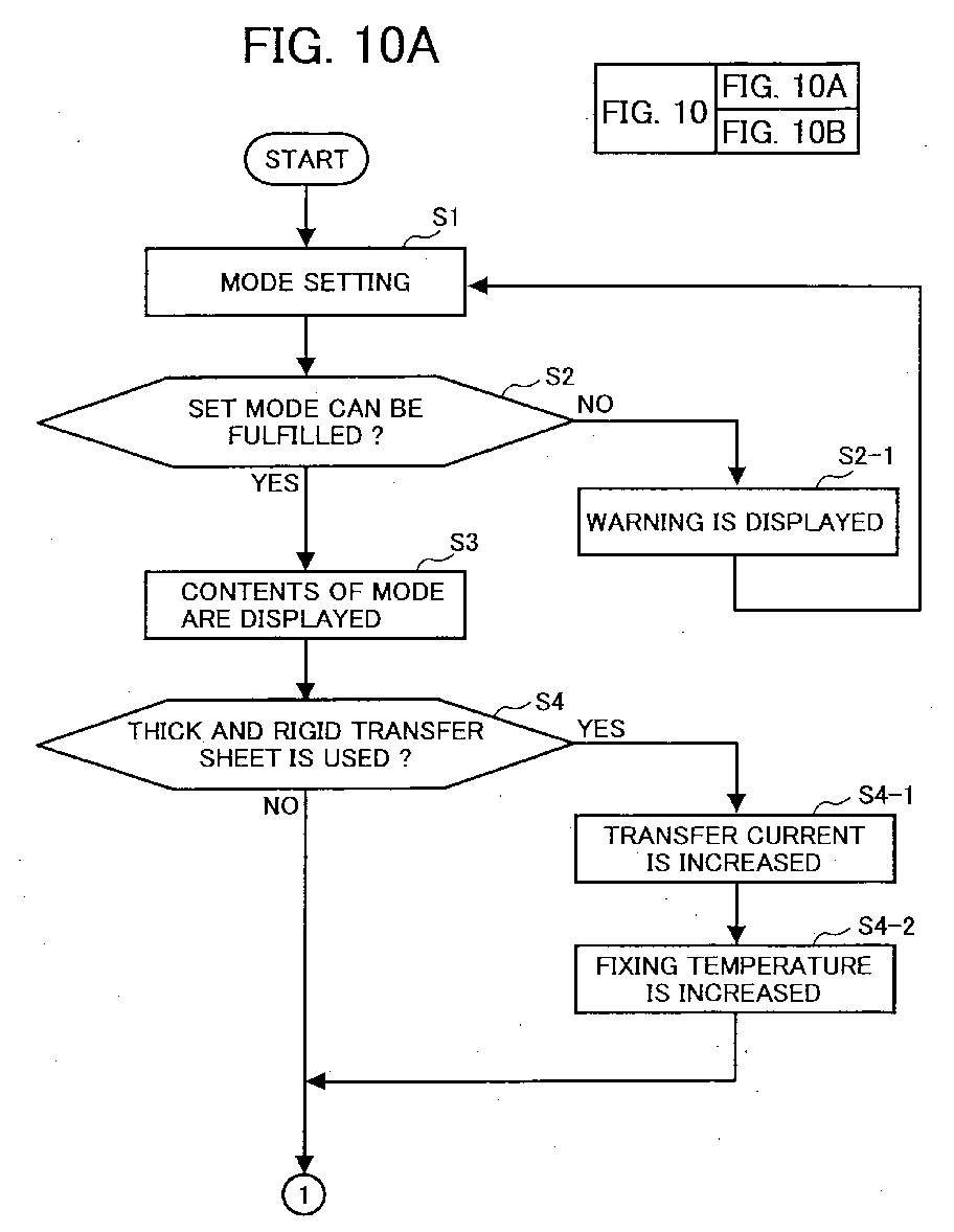
A control of an image forming condition according to a property of a used
transfer sheet is described below referring to a flowchart illustrated in Fig. 10. A mode
setting is made by a user through an operation panel of an image forming apparatus or a
host computer at step S1. The mode setting includes a designation of a sheet feeding
cassette, a sheet discharging tray and a type of a transfer sheet to be used. Whether not
the designated mode can be performed is determined at step S2. For example, when a
mode in which a thick and rigid transfer sheet and the sheet discharge tray 40 are
designated is selected, it is determined that the set mode is not fulfilled. Further, it is
determined that a set mode is not fulfilled when the thick and rigid transfer sheet is
designated and one of the sheet feeding cassettes 26-1, 26-2, 26-3 is designated for
feeding the thick and rigid transfer sheet. When it is determined that the selected mode is
not fulfilled at step S2 (i.e., "No" at step S2), a warning is displayed on a screen of the
operation panel and/or a monitor of a host computer at step S2-1 so as to notify the
erroneous mode setting. When the set mode can be fulfilled, the contents of the set
mode are displayed on the screen of the operation panel and/or the monitor of the host
computer at step S3.
-
When the thick and rigid transfer sheet is designated in the set mode, the process
proceeds to step S4-1 from step 4. A transfer condition is set such that a transfer current
is increased by about 10 to 30% compared to that applied when a normal transfer sheet is
used. The process further proceeds to step S4-2. Thus, a fixing temperature is set such
that the fixing temperature is increased by about 10 to 30% compared to that when the
normal transfer sheet is used. When the normal transfer sheet is designated in the set
mode, the process proceeds to step S5 without increasing the transfer current and the
fixing temperature.
-
Whether or not a both-surface printing is designated is determined at step S5.
When the both-surface printing is designated, the process proceeds to S5-1 to
independently control the temperature of the fixing rollers 18 and 19. At step S6, a
control sequence (i.e., the order of pages of the formed images, and whether or not an
image is transferred onto the second image bearing member, etc.) and image forming
conditions (i.e., a transfer current and a fixing temperature, etc.) are determined
according to the set mode and conditions. Then, an image forming operation is
performed at step S7.
-
Fig. 11 is a block diagram illustrating a control section that exerts the above-described
control. A main control board 70 includes a CPU, a ROM, and a RAM. The
main control board 70 controls the exposure device 7, transfer devices 21, 22 and CH,
cleaning device 2, sheet feeding devices 26 and 35, fixing devices 30 and 30B, and
switching pick 36. The main control board displays the contents of the set mode and an
alarm on the operation panel 50 or outputs them to a host computer.
-
Fig. 12 is a schematic drawing illustrating a sectional view of an image forming
apparatus which is capable of forming a full color image according to another example of
the present invention. In the image forming apparatus, the image forming section PU is
arranged approximately in the center of a main body of the apparatus. The image
forming section PU includes four image forming units SU. The four image forming
units SU are provided in series along the lower run of the inclined intermediate transfer
belt 60 such that they contact the intermediate transfer belt 60. The exposure device 7 is
disposed below the image forming units SU. The construction of each image forming
unit SU is identical to that described in Fig. 9 except for a position of the surrounding
components.
-
The intermediate transfer belt 60 rotates in a counterclockwise direction as
indicated by an arrow in Fig. 12 while being spanned around the driving roller 61 and
the driven roller 62. The belt cleaning device 25 is provided at the position of the driven
roller 62. A toner containing section TS including a toner cartridge TC that contains
replenishing toner is disposed above the intermediate transfer belt 60. Each toner
cartridge labeled with "a" to "d" contains cyan, magenta, yellow, and black toner,
respectively. Each color toner is supplied to the corresponding developing device by a
powder pump (not shown).
-
Each cyan, magenta, yellow, and black toner image formed on the surface of the
respective photoconductive drums 1a-1d is transferred on the intermediate transfer belt
60 one after another so that a full color image is formed thereon. When a black and
white image is formed, the image is formed in the image forming unit SU that contains
black toner. The formed black and white image is then transferred on the intermediate
transfer belt 60.
-
The intermediate transfer member 110 is provided on the right side of the image
forming section PU. The intermediate transfer member 110 is spanned around rollers
113, 115, 116, and 117 such that it rotates in a counterclockwise as illustrated by an
arrow in Fig. 12. A transfer roller 120, which is a transfer device, is arranged adjacent
to the roller 11, which supports the intermediate transfer belt 60, within a run of the
intermediate transfer member 110. Further, a heating roller 130, rollers 114 and 115,
and a backing plate BP are disposed within the run of the intermediate transfer member
110. The roller 116 also serves as a cooling device. A belt cleaning device 250 and a
charger CH are provided outside the run of the intermediate transfer member 110. The
belt cleaning device 250 includes a roller 250A, a blade 250B, and a toner conveying
device 250C inside. The belt cleaning device 250 removes residual toner and a paper
powder remaining on the surface of the intermediate transfer belt 60 after a toner image
is transferred onto a transfer sheet. In Fig. 12, the roller 250A is separated from the
surface of the intermediate transfer belt 60. The roller 250A is configured to be rotatable
over a fulcrum 250D such that it can be brought into contact with or separated from the
surface of the intermediate transfer belt 60. The roller 250A is separated from the
surface of the intermediate transfer belt 60 when the intermediate transfer belt 60 carries
a toner image to be transferred onto a transfer sheet. The roller 250A is rotated in a
counterclockwise direction in Fig. 12 so as to contact the surface of the intermediate
transfer belt 60 when a cleaning of the intermediate transfer belt 60 is required.
-
The intermediate transfer belt 60 and the intermediate transfer member 110 are
brought into contact with each other by the transfer roller 120, roller 115, and roller 11
(which supports the intermediate transfer belt 60) so as to form a predetermined nip.
The charger CH is arranged outside the run of the intermediate transfer member 110 at a
position opposed to the backing plate BP which is disposed above the transfer roller 120.
-
Sheet feeding devices (i.e., sheet feeding cassettes) 26-1 and 26-2 are vertically
arranged below the image forming section PU in a lower portion of the apparatus. The
uppermost transfer sheet stacked in each sheet feeding cassette 26-1 and 26-2 is fed
sheet-by-sheet by the sheet feeding roller 27 and is conveyed to the pair of registration
rollers 28 while being guided by each guide member 29.
-
The fixing device 30 is provided at a position opposed to the heating roller 130
which is disposed within the run of the intermediate transfer member 110. The fixing
device 30 is configured such that the fixing roller 19 is brought into contact with the
intermediate transfer member 110 by a contact/separation mechanism (not shown) like
the fixing device 30 described referring to Fig. 1. In Fig. 12, the fixing roller 19 is
brought into contact with the intermediate transfer member 110.
-
When a both-surface printing is performed, the first image formed in the image
forming section PU is transferred onto the intermediate transfer member 110 from the
intermediate transfer belt 60. The second image is then formed in the image forming
section PU. The second image is transferred onto the second surface of a transfer sheet,
which is conveyed by the pair of registration rollers 28, from the intermediate transfer
belt 60. The transfer of the second image is performed by the transfer roller 120 which
is disposed within the run of the intermediate transfer member 110. The first image
transferred on the intermediate transfer member 110 which is circled while being carried
by the intermediate transfer member 110 is brought in register with the first surface of
the transfer sheet. The transfer sheet having the second surface on which the second
image is transferred and the first surface which is in register with the first image carried
on the intermediate transfer member 110 is conveyed in an upward direction by the
intermediate transfer member 110. The first image carried on the intermediate transfer
member 110 is transferred onto the first surface of the transfer sheet by the charger CH.
The transfer sheet having toner images on the both surfaces thereof is conveyed to a
fixing region. The toner images are fixed onto the transfer sheet by the fixing roller 19
of the fixing device 30 and the heating roller 130. When a fixing operation is performed,
the fixing roller 19 of the fixing device 30 is brought into press-contact with the heating
roller 130 via the intermediate transfer member 110. The transfer sheet having fixed
toner images is discharged to the sheet discharge tray 40 by the pair of sheet discharging
rollers 34.
-
When a one-surface printing is performed, an image is not transferred on the
intermediate transfer member 110. The image formed in the image forming section PU
is directly transferred onto a transfer sheet from the intermediate transfer belt 10.
-
As described above, according to the example of the present invention, a toner
image formed in the image forming section PU is transferred on the transfer sheet or the
intermediate transfer member 110 from the intermediate transfer belt 60. Thus, the
intermediate transfer belt 60 in the image forming section PU and the intermediate
transfer member 110 correspond to the first and second image bearing member,
respectively.
-
In this example of the present invention, when a thick and rigid transfer sheet,
such as a cardboard and an envelope is used, a transfer current is increased by about 10
to 30% compared to that applied when a normal transfer sheet is used like the above-described
example. When the thick and rigid transfer sheet is used, a fixing temperature
is increased by about 10 to 30% compared to that when the normal transfer sheet is used.
When the temperature of the fixing roller 19 and the heating roller 130 is independently
controlled based on a one-surface and both-surface printing, further appropriate fixing
performance is accomplished. A temperature detecting device may be provided to the
fixing roller 19 and the heating roller 130 such that a respective heaters of the fixing
roller 18 and the heating roller 130 are controlled based on a detection of the temperature
detecting device.
-
The apparatus according to this example does not include a manual sheet feeding
device and an exit tray provided to the side of a main body of the apparatus. However,
because a transfer sheet is fed from the sheet feeding cassettes 26-1 and 26-2 and is
discharged to the sheet discharging tray 40, a transfer sheet conveying path is arranged
comparatively in a straight line. Thus, a thick and rigid transfer sheet can be used.
-
As illustrated in Fig. 13, a portion of the apparatus including the intermediate
transfer member 110 is opened relative to the main body of the apparatus. The open
portion of the apparatus includes the intermediate transfer member 110, components
arranged within the run of the intermediate transfer member 110, the belt cleaning device
250 and so forth. An upper roller 34a of the pair of the sheet discharging rollers 34 is
provided to the open portion and a lower roller 34b of the pair of the sheet discharging
rollers 34 is provided to the main body of the apparatus. As shown in Fig. 13, when the
open portion of the apparatus is opened, a space between sheet feeding cassettes provided
in a lower portion of the apparatus and the pair of sheet discharging rollers 34 provided
in an upper portion of the apparatus is opened, thereby improving a removability of a
jammed sheet.
-
Fig. 14 is a schematic drawing illustrating another example of an image forming
apparatus in which the fixing device 30B is provided at a position different from that of
the fixing device 30 in Fig. 12 (i.e., the fixing device 30B is separated from the
intermediate transfer member 110). Because the structure of the apparatus is identical to
that illustrated in Fig. 12 except for the location of the fixing device 30B, explanation of
the devices similar to those in Fig. 12 are omitted. As shown in Fig. 15, the fixing
device 30B is fixedly provided to a main body of the apparatus. Thus, when the open
portion is opened, the fixing device 30B is supported by the main body of the apparatus.
If the fixing device 30B is configured such that two fixing rollers are separated when the
open portion is opened, a removability of a jammed sheet is improved.
-
Fig. 16 is a diagram illustrating two printers, which are illustrated in Fig. 12 or
Fig. 14, are connected to the host computer HC on a network. The printers may be
connected to the host computer HC over-the-air without using a cable. An abbreviated
word "OP" denotes an operation panel.
-
In the printer illustrated in Fig. 12 or Fig. 14, the undersurface of the sheet
discharge tray 40 serves as a cover 40A for the toner containing section TS. The cover
40A is opened/closed around a rotation axis 40B. As illustrated in Fig. 16, when the
cover 40A is opened, a replacement of a toner cartridge is easily performed. Because the
rotation axis 40B is arranged on the side of the pair of sheet discharging rollers 34, the
discharged transfer sheets may not drop from the sheet discharge tray 40 and an
inconvenience in which the collated pages of the transfer sheets are disordered is
obviated even when the cover 40A is opened.
-
A door 67 provided to the front side of the apparatus is rotatably opened in a
direction indicated by an arrow in Fig. 16 around the left side of the door 67. When the
door 67 is opened, an operator reaches a hand to the image forming section PU to
perform maintenance of the image forming section PU. The image forming section PU
including the intermediate transfer belt 60, the four image forming units SU, and
components provided around each of the four image forming units SU can be slid out of
the apparatus while leaving the exposing device 7 in the main body of the apparatus. The
intermediate transfer belt 60 and each image forming unit SU can be removed while the
image forming section PU is slid out. Rails (not shown) are provided such that the
image forming section PU is slid out on the rails. Because the door 67 is supported by a
hinge provided in a direction perpendicular to the door 67, a visibility of maintenance
parts is increased when the door 67 is opened. Further, replenishing the sheet feeding
cassettes 26-1 and 26-2 with a transfer sheet is easily performed. A sealing material (not
shown) is arranged such that the component of the exposing device 7 is not contaminated
by toner, etc. An exposure operation of the exposing device 7 is performed to form a
mirror image and a normal image, which is controlled by a controller (not shown) that
controls a writing operation.
-
Further, the sheet feeding cassettes 26-1 and 26-2 are configured to be slid out
in a direction indicated by an arrow in Fig. 16. A replenishment and replacement of a
transfer sheet are performed while the sheet feeding cassettes 26-1 and 26-2 are slid out.
In the printer illustrated on the right end portion of Fig. 16, the door 67 is opened and
the sheet feeding cassette 26-2 is slid out.
-
Fig. 17 is a schematic drawing illustrating a sectional view of another example
of an image forming apparatus in which the construction of the image forming section
PU is different from that illustrated in Fig. 14. In this example, the intermediate transfer
belt 60 is spanned into a triangle shape in the image forming section PU. The four image
forming units SU are horizontally provided in series along the lower run of the
intermediate transfer belt 60. The exposing device 7 is horizontally arranged below the
four image forming units SU. The construction of this image forming apparatus other
than the above-described construction is similar to that illustrated in Fig. 4. Thus, an
explanation of the devices similar to those in Fig. 14 is omitted.
-
Fig. 18 is a schematic drawing illustrating a sectional view of another example
in which the image forming section PU is differently constructed from those examples
illustrated in Figs. 14 and 17. According to this example, the intermediate transfer belt
60 is spanned such that the upper run of the intermediate transfer belt 60 is horizontal in
the image forming section PU. The four image forming units SU are horizontally
disposed in series along the upper run of the intermediate transfer belt 60. Further, the
exposing device 7 is horizontally arranged above the four image forming units SU. The
construction of this image forming apparatus other than the above-described construction
is similar to that illustrated in Fig. 14. Thus, an explanation of the devices similar to
those in Fig. 14 is omitted.
-
According to the example illustrated in Fig. 18, an original image reading
device 200 and an automatic document feeder ADF 250 are installed on a printer 100D
using a supporting stand STD to be used as a copying machine. Fig. 19 is a perspective
view illustrating the original image reading device 200, ADF 250, and STD.
-
The original image reading device 200 and ADF 250 are explained below
referring to Fig. 18. Platens 202 and 203 are provided above a frame 201 of the original
image reading device 200.The large platen 202 is used when reading an original image
while fixedly placing an original document on the platen 202.The small platen 203 is
used when reading the original image while conveying the original document by the ADF
250.
-
A first carriage 204 including a light source and a mirror and a second carriage
205 including two mirrors are movably provided in parallel with the platen 202 in the
original image reading device 200. The second carriage 205 moves at half speed of the
first carriage 204 employing a commonly known optical system. The first and second
carriage 204 and 205 moves and scans the image of the original document placed on the
platen 202. When reading the image of the original document while the original
document is conveyed, the first and second carriage 204 and 205 scans the image of the
original document conveyed on the platen 203 while the first and second carriage 204
and 205 stay at a position illustrated in Fig. 18.
-
The original document is irradiated with the light source. The light reflected
from the original document is focused by a fixed lens 206 so as to form an image on a
CCD (Charge-Coupled Device) 207.This data is processed as a digital signal. The
processed date is transmitted to a remote location by a facsimile function or is printed by
the image forming apparatus according to the example of the present invention. The data
may be input into a computer so as to perform an image process.
-
The ADF 250 includes an original document table 251 on which a stack of the
original documents is placed. The original document table 251 includes a movable plate
252. The left side portion of the original document table 251 in Fig. 18 is a sheet
conveying section 253 of the ADF 250. In the sheet conveying section 253, a sheet
feeding roller 254 disposed above a tip of the movable plate 252, a pair of separating
rollers 255, a pair of conveying rollers 256 are disposed. Further, an image sensor, a
conveying roller 257 which is arranged at a position opposed to the image sensor 258, a
pressure plate 259, a conveying roller 260, and a pair of sheet discharging rollers 261
are provided. An original document discharging tray 262 is provided below the original
document table 251. A space in which transfer sheets are discharged is formed between
the original document table 251 and the original document discharging tray 262. A
pressure plate 263 is arranged at the bottom of the original document discharging tray
262 such that the pressure plate 263 presses the original documents placed on the platen
202. A white sheet is affixed to the bottom surface of the pressure plate 263 (i.e., the
surface faces the platen 202). The ADF is opened together with the pressure plate 263 in
a direction separating from the platens 202 and 203. The pressure plate 263 is configured
to press the original document even if a thick original document, such as a book is placed
on the platen 202. It is convenient to use the ADF 250 when the original document is
sheet-formed.
-
A plurality of sheet-like original documents are placed on the movable plate 252
of the original document table 251 with a first page of the plurality of the sheet-like
original documents face up. The sheet feeding roller 254 rotates in a direction indicated
by an arrow (i.e., in a clockwise direction) to feed and convey the uppermost original
document to the sheet conveying section 253.The original document is conveyed sheet-by-sheet
by the pair of separating rollers 255. The original document is discharged in a
direction indicated by an arrow in Fig. 18 from the pair of sheet discharging rollers 261
via the pair of conveying rollers 256, conveying rollers 257 and 260. The discharged
original documents are stacked on the original document
-
An image on a second page of the original document is read by the image sensor
258. An image on a first page of the original document is read by the original image
reading device 200 while the original document is conveyed through a space formed
between the pressure plate 259 and the platen 203. When the image of the original
document is read while the original document is conveyed through the space formed
between the pressure plate 259 and the platen 203, the first and second carriages stay at
respective image reading positions.
-
Namely, when the sheet-like original document is fed by the ADF 250, images
formed on both surfaces of the sheet-like original document are read at differently
arranged two image reading positions. An original image reading section while the
original document is conveyed is referred to as "Y1". An original image reading section
while the original document is fixed and read by the carriages 204 and 205 is referred to
as "Y2".
-
In Fig. 18, the image sensor 258 in the ADF 250 is marked with the reference
numeral Y1. Y2 is marked in the original image reading device 200. Y2 serves as a
part of Y1 when reading the original image while conveying the original document by
ADF 250. Namely, Y1 includes the image sensor 258 in the ADF 250 and a part of Y2.
-
When an original document is thin, a color of a pressure plate may be read
through the original document as a background by an image reading device. Thus, a
white sheet is affixed to the surface of the pressure plate 263 that faces the original
document. For the same reason as described above, the conveying roller 257 and
pressure plate 259 are made to be white.
-
Fig. 20 is a diagram illustrating a sectional view of the image sensor 258. The
image sensor 258 includes a glass 27I which faces an original document, a light source to
irradiate the original document, such as a LED array 272, a lens array 273 which is an
image focusing member, and a same size magnification sensor 274. Other type of image
sensor, for example, a contact-type image sensor in which a focusing lens is not used,
may be employed.
-
In the ADF 250 illustrated in Fig. 18, when a thick book is placed in the
original image reading section Y2 as an original document, the original document is
pressed by the pressure plate 263. However, the original image reading section Y1,
which is integrally constructed with the ADF 250, is slightly lifted. Thus, the pressure
plate 259 is separated from the platen 203. A sensor (not shown) to detect that the
pressure plate 259 is separated from the platen 203 is provided. Based on the detection
result of the sensor, use of the original image reading section Y1 is prohibited.
-
When an image forming operation is urgently required while an image of a
sheet-like original document is read in the original image reading section Y1, the original
image reading section Y2, in which the platen 202 and pressure plate 263 are used, is
used for an interruption work, even if the sheet-like original document exists on the
original document table 251 or on the original document discharging tray 262. The
interruption work is designated by pressing a key in the operation panel OP (see Fig.
16).
-
Fig. 21 is a perspective view illustrating an optional sheet feeding device 264
and the original image reading device 200 are installed to the printer 100D. In Fig. 21,
the pressure plate 263 of the original image reading device 200 is opened.
-
Fig. 22 is a schematic drawing illustrating another example of a printer.
According to this example, the printer 100E includes an optional sheet feeding device for
a long transfer sheet. Because the basic construction of the printer 100E is similar to that
of the printer 100 illustrated in Fig. 1, the devices that are different from those of the
printer 100 are described below.
-
As illustrated in Fig. 22 sheet feeding cassettes 261 and 262 are vertically
arranged at a lower portion of a main body of the printer 100E. A rolled sheet feeding
device 300 is provided to the sides of the main body of the printer 100E and the sheet
feeding cassettes 261 and 262. Further, a long transfer sheet holder 310 is provided to
the manual sheet feeding device 35. A long transfer sheet exit tray 45 is provided to the
opposite side of the sheet feeding cassettes 261 and 262 where the rolled sheet feeding
device 300 is provided. The long transfer sheet exit tray 45 is slid into or out of the space
provided between the sheet feeding cassettes 261 and 262.
-
The sheet feeding trays 261 and 262 are provided to feed an increased number
of transfer sheets in a plurality of sizes while containing a normal-sized transfer sheet
(i.e., transfer sheet not larger than A-3 size).
-
The long transfer sheet holder 310 holds a long transfer sheet LP while rolling it
and feeds the long transfer sheet LP. The long transfer sheet LP is manually rolled and
placed into the long transfer sheet holder 310. A tip portion of the long transfer sheet LP
is reeled out from an outlet provided at an upper portion of the long transfer sheet holder
310 so that a leading edge of the long transfer sheet LP is caught by the sheet feeding
roller 36. The long transfer sheet holder 310 is installed to a holder mounting part 311 of
the manual sheet feeding device 35.
-
The rolled sheet feeding device 300 contains a rolled transfer sheet RP such that
the rolled transfer sheet RP is reeled out. The rolled transfer sheet RP is conveyed to the
main body of the printer 100E by pairs of sheet conveying rollers 301 and 302. The
rolled transfer sheet RP is then cut into a predetermined length by a cutter 303. The
rolled transfer sheet RP cut into the predetermined length is conveyed to the pair of
registration rollers 38 by a pair of sheet conveying rollers 39.
-
The long transfer sheet holder 310 and the rolled sheet feeding device 300 can
be installed as an optional device, thereby reducing a economic burden of a user who
does not require these optional devices. The user can minimize an initial cost required for
obtaining the apparatus because these optional devices can be separately obtained when
these devices are required. The long transfer sheet holder 310 and the rolled sheet
feeding device 300 can be installed to the printer 100 illustrated in Fig. 1 as an optional
device.
-
Because an image forming process is performed in a similar manner to that
described referring Figs. 5A-5D, an explanation is omitted.
-
When an image is printed on a long transfer sheet, which is longer than the
circumferential length of the intermediate transfer belt 10, a faulty image is produced if a
both-surface printing is selected. Because the second image bearing member can not
carry the whole image to be printed onto such a long transfer sheet. Thus, the printer
100E is configured such that the both-surface printing is prohibited when the long
transfer sheet is used. An image, which is longer than the circumferential length of the
intermediate transfer belt 10, can not be printed even if a one-surface printing is
performed, when the image is printed on the underside of the long transfer sheet (i.e.,
the surface of the long transfer sheet on the side of the intermediate transfer belt 10).
Thus, the printer 100E is configured such that the one-surface printing on the surface of
the transfer sheet, which is on the side of the intermediate transfer belt 10, is prohibited
when the long transfer sheet is used.
-
However, an image formed on the surface of the photoconductive drum 1 (i.e.,
first image bearing member) can be directly transferred onto the long transfer sheet.
Thus, the printer 100E is configured such that the image is transferred onto the surface
of the transfer sheet which is on the side of the photoconductive drum 1, when the long
transfer sheet is used.
-
When the long transfer sheet is used, an amount of heat supplied by a fixing
device tends to be insufficient, even if the one-surface printing is performed. Therefore,
fixing performance is decreased in order of a portion of the long transfer sheet i.e., in
order of a leading portion to a trailing portion of the long transfer sheet. Thus, according
to the example of the present invention, when the long transfer sheet is used, a fixing
temperature is set at a higher level compared to that when a normal transfer sheet is
used. In the printer 100E, the largest normal transfer sheet is A-3 size. Thus, a transfer
sheet having the length more than that of the A-3 sized transfer sheet is referred to as the
long transfer sheet in this example. Other maximum sheet sizes may be used as threshold
size as well.
-
Figs. 23A and 23B are diagrams illustrating a change in the fixing temperature
when the normal and long transfer sheets are used, respectively.A-3 sized transfer sheet
(i.e., 420 mm in length) and a long transfer sheet (i.e., 900 mm in length) are used in
Figs. 23A and 23B, respectively. In the diagrams, y-axis and x-axis represent a
temperature and a period of time in which a transfer sheet is conveyed through the fixing
device, respectively.
-
In Fig. 23A, "T1" is a fixing temperature set when the normal transfer sheet is
used. The temperature of the fixing device (i.e., fixing roller) is increased to a level
which is higher than the set temperature of "T1" before the transfer sheet is conveyed to
a fixing region. The temperature then decreases to the set temperature. An energization
of a fixing heater is controlled to maintain the set temperature, when the temperature of
the fixing device decreases because the heat is absorbed by the transfer sheet which
passes through the fixing region. When the transfer sheet has passed through the fixing
region, the energization of the fixing heater is stopped. Then, the temperature of the
fixing device decreases.
-
In Fig. 23B, "T2" is a fixing temperature set when the long transfer sheet is
used. "T2" is higher than "T1" (i.e, T1 < T2). The long transfer sheet of 900 mm in
length, which is far longer than the circumferential length of the intermediate transfer
belt 10, is used. Because "T2" is set at a temperature higher than that of "T1" by about
10 to 30 % , the decrease of the temperature of the fixing device is suppressed while the
long transfer sheet passes through the fixing region, thereby preventing a faulty fixing.
-
An operation for recording an image on the long transfer sheet is described
below referring to Fig. 22. When the long transfer sheet LP is used, the tip portion of
the long transfer sheet LP is reeled out from the long transfer sheet holder 310 so that the
leading edge of the long transfer sheet LP is caught by the sheet feeding roller 36.
-
When the rolled transfer sheet RP is used, a sheet feeding instruction is provided
via the operation panel 50 (or the host computer HC). The rolled transfer sheet RP is
then reeled out by a rotation of the pair of sheet conveying rollers 301. When the rolled
transfer sheet RP is conveyed by a predetermined length by the pair of sheet conveying
rollers 302, the rolled transfer sheet RP is cut by the cutter 303. The length of the rolled
transfer sheet RP can be designated via the operation panel 50 or the host computer HC.
-
A toner image formed on the surface of the photoconductive drum 1 is directly
transferred onto the long transfer sheet LP or the rolled transfer sheet RL, which is cut
into the predetermined length, by the first transfer device 21 (hereinafter the long
transfer sheet LP and the cut rolled transfer sheet RP are collectively referred to as a
long transfer sheet). The toner image is fixed onto the long transfer sheet by the fixing
device 30B. The long transfer sheet is then discharged to the long transfer sheet exit tray
45. At this time, the switching pick 42 is switched in the direction indicated by the arrow
"J". The long transfer sheet conveyed in the direction indicated by the arrow "A2" is
discharged to the long transfer sheet exit tray 45 via the exit tray 44.In this case, the
discharged long transfer sheets are not collated by page. The long transfer sheet exit tray
45 is slid into the space formed between the sheet feeding cassettes 261 and 262 when the
tray is not used, thereby saving space required for the printer 100E.
-
When the long transfer sheet is used in the printer 100C illustrated in Fig. 6, a
both-surface printing and a one-surface printing on a surface of the long transfer sheet,
which is on the side of the intermediate transfer belt 10, are prohibited. An image is
transferred onto the surface of the long transfer sheet which is on the side of the
photoconductive drum 1. The fixing temperature is set at a higher level when the long
transfer sheet is used compared to that set when the normal transfer sheet is used. Thus,
an occurrence of a faulty fixing is prevented when the long transfer sheet is used.
-
In the printer illustrated in Fig. 6, the long transfer sheet can be fed from the
manual sheet feeding device 35. In addition, the long transfer sheet holder 310 and the
rolled sheet feeding device 300 can be installed to this printer like the printer 100E
illustrated in Fig 22.
-
Because an image forming process is performed in a similar manner to that
described referring to Figs. 7A-7D, an explanation is omitted.
-
Fig. 24 is a schematic drawing illustrating another example of a full color image
forming apparatus in which an optional device for a long transfer sheet is installed. The
construction of the image forming section is similar to that of the image forming
apparatus illustrated in Fig. 8. As is the case with the example illustrated in Fig. 22, the
sheet feeding cassettes 26, 261, and 262 are provided in a lower portion of the apparatus.
The rolled sheet feeding device 300 is provided to the right side of the apparatus. The
long transfer sheet holder 310 is provided to the manual sheet feeding device 35.
Further, the long transfer sheet exit tray 45 is provided to the left side of the apparatus.
The long transfer sheet exit tray 45 is slid into or out of the space provided between the
sheet feeding trays 261 and 262.
-
The fixing device 30B is arranged on the left side of the intermediate transfer
member 110 similar to the example illustrated in Fig. 22.
-
According to the example of the present invention, a toner image formed in the
image forming section PU is carried by the intermediate transfer belt 60. The toner
image is then transferred onto the intermediate transfer member 110 or one surface of a
transfer sheet which is conveyed by the pair of registration rollers 28. The transfer sheet
is fed by each sheet feeding cassette 26, 261, and 262 , the manual sheet feeding device
35, or the rolled sheet feeding device 300 and is conveyed to the pair of the registration
rollers 28.The transfer sheet used in the example includes a normal sheet-like transfer
sheet which is fed by the sheet feeding cassettes 26, 261, and 262, a thick and rigid
transfer sheet, such as a cardboard and envelope which is fed by the manual sheet
feeding device 35, and a long transfer sheet which is fed by the rolled sheet feeding
device 300.
-
A both surface printing is performed in a similar manner to the image forming
apparatus illustrated in Fig. 8.
-
When an image is printed on a long transfer sheet, which is longer than the
circumferential length of the intermediate transfer belt 10, a faulty image is produced if a
both-surface printing is selected. Because the second image bearing member can not
carry the whole image to be printed onto such a long transfer sheet. Thus, a printer
100F is configured such that the both-surface printing is prohibited when the long
transfer sheet is used. An image, which is longer than the circumferential length of the
intermediate transfer belt 10, can not be printed even if a one-surface printing is
performed, when the image is printed on the underside of the long transfer sheet (i.e.,
the surface of the long transfer sheet on the side of the intermediate transfer belt 10).
Thus, the printer 100F is configured such that the one-surface printing on the surface of
the transfer sheet, which is on the side of the intermediate transfer belt 10, is prohibited
when the long transfer sheet is used.
-
However, an image formed on the surface of the photoconductive drum 1 (i.e.,
first image bearing member) can be directly transferred onto the long transfer sheet.
Thus, the printer 100F is configured such that the image is transferred onto the surface of
the transfer sheet which is on the side of the photoconductive drum 1, when the long
transfer sheet is used.
-
When the long transfer sheet is used, an amount of heat supplied by a fixing
device tends to be insufficient, even if the one-surface printing is performed. Therefore,
fixing performance is decreased in order of a portion of the long transfer sheet i.e., in
order of a leading portion to a trailing portion of the long transfer sheet. Thus, according
to the example of the present invention, when the long transfer sheet is used, a fixing
temperature is increased by about 10 to 30% compared to that when a normal transfer
sheet is used. A transfer sheet that is larger than A-3 size is referred to as the long
transfer sheet in this example. Other maximum sheet sizes may be used as threshold size
as well.
-
According to the above-described examples, a toner image transferred onto the
second image bearing member i.e., the intermediate transfer belt 10 or intermediate
transfer member 110 is circled while being carried by the intermediate transfer belt 10 or
intermediate transfer member 110 before the toner image is transferred onto a transfer
sheet. Thus, the similar period of time is required to print an image irrespective of a size
of the image because the corresponding toner image is circled while being carried by the
second image bearing member. In other words, an extra period of time is spent for
printing a small size image.
-
When the small size image (i.e., an image that is small in a sub-scanning
direction) is printed, a plurality of the small size images are carried by the second image
bearing member. The plurality of the small size images are then successively transferred
onto a plurality of transfer sheets, thereby increasing efficiency and productivity. When
the both-surface printing is performed, the images are successively transferred onto the
other surface of the plurality of transfer sheets from the first image bearing member. In
this case, the second image bearing member needs to have a size in which the plurality of
the small size images are transferred.
-
For example, an A-3 size image is transferred onto the intermediate transfer belt
10 or the intermediate transfer member 110 in a vertical position. According to the
examples of the present invention, the intermediate transfer belt 10 or the intermediate
transfer member 110 carries two A-4 or B-5 size images in a horizontal position at one
time. The intermediate transfer belt 10 or the intermediate transfer member 110 carries
three or more images at one time if the images are small (e.g., a size of a business
card). Thus, when a size of an image to be formed is small, images of a plurality of
pages (i.e., "n" number of images) are successively formed. The images thus formed
are transferred onto the intermediate transfer belt 10 or the intermediate transfer member
110 in sequence such that the intermediate transfer belt 10 or the intermediate transfer
member 110 carries the plurality of images (i.e., "n" number of images)A plurality of
transfer sheets (i.e., "n" number of transfer sheets) are successively fed so that the
images are transferred onto the respective plurality of transfer sheets. When a both-surface
printing is performed, the order of pages of the transfer sheet on which images
are printed is different from that when a one-surface printing is performed. However,
the change of the pages is accomplished by a commonly known technology in which
image data is stored and read.
-
In this operation, a plurality of prints are performed by one turn of the
intermediate transfer belt 10 or intermediate transfer member 110. The operation in
which the second image bearing member bears a plurality of images and successively
transfers the plurality of images onto a plurality of transfer sheets (hereinafter referred to
as a successive small size print) is designated through an operation panel of the apparatus
or a host computer. In the successive small size print operation, a transfer sheet is
conveyed at a different intervals from that when a normal size print operation is
performed. Thus, when the successive small size print is designated, the time to form an
image and to convey a transfer sheet is controlled based on the intervals that the transfer
sheet is conveyed.
-
In the above-described examples of the present invention, the successive small
size print can be performed when a size of a transfer sheet (i.e., a size of an image) is
not larger than A-4 size in a horizontal position. Thus, an image transfer process is
controlled such that the successive small size print is prohibited for the transfer sheet
larger than A-4 size.
-
Fig. 25 is a flowchart illustrating the control of the image forming conditions
when a long transfer sheet is used. Steps S1 to S3 is similar to those described in Fig.
10. At step S4, whether or not the long transfer sheet is used is determined. When the
long transfer sheet is used, a transfer process is controlled such that a both-surface
printing and one-surface printing on the surface of the transfer sheet facing to the second
image bearing member are prohibited at step S4-1. A fixing temperature is increased by
about 10 to 30% compared to that when a normal transfer sheet is used at step S4-2.
-
At step S5, whether or not a successive small size print is designated is
determined. When the successive small size print is designated, whether or not a size of
an image (i.e., a size of a transfer sheet) is larger than A-4 size in a horizontal position is
determined at step S5-1. When the size of the image (i.e., the transfer sheet) is not
larger than A-4 size, the process proceeds to step S6. When the size of the image (i.e.,
the transfer sheet) is larger than A-4 size, an image transfer operation onto the second
image bearing member is prohibited at step S5-2. In addition, an alarm is displayed at
step S5-3. The process proceeds to step S1 to set a mode. The process performed in
steps S6 to S8 is similar to that performed in the steps S5 to S7 in Fig. 10.
-
While this invention is described in conjunction with the examples outlined
above, it is evident that many alternatives, modifications and variations will be apparent.
For example, although the transfer devices 21 and 65 are configured to be a roller-type
that contacts the intermediate transfer belt 10 (and 60) according to the above-described
example, a transfer device in a brush-type or a roll-shaped brush-type may be used.
Further, a discharge-type (i.e., a charger) that does not contact the intermediate transfer
belt 10 (and 60) may be employed.
-
A belt-type image bearing member may be used instead of the photoconductive
drum 1. Then, an appropriate charging device, a developing device, a fixing device etc.,
may be adopted for the belt-type image bearing member. The configuration of the
operation panel 50 (and OP) and an arrangement of setting button is not limited to the
above-described examples.
-
The fixing device 30, in which a fixing operation is performed while retaining a
transfer sheet on the intermediate transfer belt 10, used in the printer 100 illustrated in
Fig. 1 may be used in the printers 100B and 100C illustrated in Figs. 4 and 6,
respectively. Further, in the image forming apparatus illustrated in Fig. 8, a fixing
operation may be performed while retaining a transfer sheet on the intermediate transfer
member 110. The image forming apparatus includes a copying machine and a facsimile
without limiting to a printer.
-
Obviously, numerous additional modifications and variations of the present
invention are possible in light of the above teachings. It is therefore to be understood
that within the scope of the appended claims, the present invention may be practiced
otherwise than as specifically described herein.
-
This document claims priority and contains subject matter related to Japanese
Patent Application No. 2000-328955, filed on October 27, 2000, Japanese Patent
Application No. 2000-330567, filed on October 30, 2000, Japanese Patent Application
No. 2001-305635, filed on October 1, 2001, Japanese Patent Application No. 2001-310057,
filed on October 5, 2001, and the entire contents thereof are herein incorporated
by reference.
-
Preferred embodiments and/or advantageous features of the invention:
- A) An image forming apparatus, comprising:
- a first image bearing member (1, 60) configured to transfer a visible image onto one
surface of a recording medium; and
- a second image bearing member (10, 110) configured to transfer a visible image, which
has been transferred from said first image bearing member, onto the other surface of the
recording medium such that visible images are transferred onto both surfaces of the
recording medium,
wherein an image forming condition including a fixing condition is controlled
differently depending on a specific property of a recording medium. - B) The image forming apparatus as indicated in embodiment A), further comprising:
- a first transfer device (21, 120) configured to transfer the visible image borne by said
first image bearing member (1, 60) onto said second image bearing member or onto one
surface of the recording medium; and
- a second transfer device (22, CH) configured to transfer the visible image borne by said
second image bearing member (10, 110) onto the other surface of the recording medium,
wherein, the visible images transferred onto the recording medium are fixed while the
recording medium is placed on said second image bearing member. - C) The image forming apparatus as indicated in embodiment A), wherein a first image
formed on a surface of said first image bearing member (1, 60) is transferred onto said
second image bearing member (10, 110) and a polarity of the first image on said second
image bearing member is reversed so that the first image and a second image formed on
the surface of said first image bearing member are transferred onto respective surfaces of
the recording medium at one time.
- D) The image forming apparatus as indicated in anyone of embodiments A) to C),
further comprising a contacting transfer device (21, 120) provided at a position opposed to
said first image bearing member (1, 60) and configured to contact a non-image bearing
surface of said second image bearing member (10, 110).
- E) The image forming apparatus as indicated in anyone of embodiments A) to D),
further comprising a sheet feeding device (35) and a sheet discharging device (44) arranged
such that a sheet conveying path between the sheet feeding device and the sheet
discharging device is approximately straight.
- F) The image forming apparatus as indicated in anyone of embodiments A) to E),
wherein the specific property of the recording medium includes a thickness of the
recording medium.
- G) The image forming apparatus as indicated in anyone of embodiments A) to E),
wherein the specific property of the recording medium includes that the recording medium
has a portion where the recording medium is folded into two.
- H) The image forming apparatus as indicated in anyone of embodiments A) to E),
wherein the specific property of the recording medium includes a smoothness of the
recording medium.
- I) The image forming apparatus as indicated in anyone of embodiments A) to H),
wherein the image forming condition controlled for the recording medium having the
specific property includes a transfer condition.
- J) The image forming apparatus as indicated in embodiment I), wherein the controlled
transfer condition includes an order of a transfer process.
- K) The image forming apparatus as indicated in embodiment I), wherein the controlled
transfer condition includes an output of a transfer bias applied to a transfer device (21, 22,
120, CH) in a visible image transfer process onto the recording medium.
- L) The image forming apparatus as indicated in anyone of embodiments A) to K),
wherein the fixing condition controlled for the recording medium having the specific
property includes a fixing temperature for fixing an image on one surface of the recording
medium or on both surfaces of the recording medium.
- M) The image forming apparatus as indicated in anyone of embodiments A) to L),
further comprising a plurality of sheet discharging devices (40, 44) in which a printed
recording medium is collated by a different order of pages, wherein the sheet discharging
device is selected for the recording medium having the specific property.
- N) The image forming apparatus as indicated in embodiment M),wherein
the selection of the sheet discharging device (40, 44) includes the sheet discharging device
in which a discharged printed recording medium is collated by page. - O) The image forming apparatus as indicated in embodiment M),
wherein the selection of the sheet discharging device (40, 44) includes the sheet
discharging device in which the recording medium is discharged without being reversed
for the recording medium having the specific property. - P) The image forming apparatus as indicated in anyone of embodiments A) to O),
wherein said second image bearing member (10, 110) is formed in an endless belt and is
extended close to a fixing region.
- Q) The image forming apparatus as indicated in anyone of embodiments A) to P), further
comprising a manual sheet feeding device (35), wherein when the recording medium is fed
from the manual sheet feeding device, the recording medium is recognized as the recording
medium having the specific property.
- R) The image forming apparatus as indicated in anyone of embodiments A) to Q),
wherein the recording medium having the specific property, for which the image forming
condition including the fixing condition is controlled, is designated through an operation
panel (50, OP).
- S) The image forming apparatus as indicated in anyone of embodiments A) to Q),
wherein the recording medium having the specific property, for which the image forming
condition including the fixing condition is controlled, is designated through an external
apparatus (HC) connected to the image forming apparatus.
- T) A method for forming an image, comprising:
- transferring a visible image from a first image bearing member (1, 60) to a second image
bearing member (10, 110);
- transferring the visible image transferred onto the second image bearing member onto
one surface of a recording medium;
- transferring a visible image from the first image bearing member onto the other surface
of the recording medium so as to form the visible images on both surfaces of the recording
medium;
- an image forming condition including a fixing condition is controlled differently
depending on a specific property of a recording medium.
- U) The method as indicated in embodiment T), wherein
the visible images transferred onto the recording medium are fixed while the recording
medium is placed on the second image bearing member. - V) A method for forming an image, comprising:
- transferring a first image formed on a surface of a first image bearing member (1, 60) to
a second image bearing member (10, 110);
- forming a second image on the surface of the first image bearing member;
- reversing a polarity of the first image transferred onto the second image bearing
member; and
- transferring the first and second images onto respective surfaces of the recording
medium at one time; wherein
- an image forming condition including a fixing condition is controlled differently
depending on a specific property of a recording medium.
- W) An image forming apparatus, comprising:
- a first image bearing member (1, 60) configured to transfer a visible image onto one
surface of a recording medium; and
- a second image bearing member (10, 110) configured to transfer a visible image which
has been transferred from said first image bearing member onto the other surface of the
recording medium such that visible images are transferred onto both surfaces of the
recording medium,
wherein an image forming condition is controlled based on a length of the recording
medium, and the length of the recording medium is based on a circumferential length of
said second image bearing member. - X) The image forming apparatus as indicated in embodiment W), further comprising:
- a first transfer device (21, 120) configured to transfer the visible image borne by said
first image bearing member (1, 60) onto said second image bearing member (10, 110) or
onto one surface of the recording medium; and
- a second transfer device (22, CH) configured to transfer the visible image borne by said
second image bearing member onto the other surface of the recording medium,
wherein, the visible images transferred onto the recording medium are fixed while the
recording medium is placed on said second image bearing member. - Y) The image forming apparatus as indicated in embodiment W), wherein a first image
formed on a surface of said first image bearing member (1, 60) is transferred onto said
second image bearing member (10, 110) and a polarity of the first image on said second
image bearing member is reversed so that the first image and a second image formed on
the surface of said first image bearing member are transferred onto respective surfaces of
the recording medium at one time.
- Z) The image forming apparatus as indicated in anyone of embodiments W) to Y),
wherein a plurality of images are transferred onto said second image bearing member (10,
110), and the plurality of images are transferred one after another onto a plurality of
successively conveyed recording mediums.
- AA) The image forming apparatus as indicated in anyone of embodiments W) to Z),
wherein the image forming condition is controlled differently when the length of the
recording medium exceeds the circumferential length of said second image bearing
member (10, 110).
- AB) The image forming apparatus as indicated in embodiment AA), further comprising a
plurality of sheet feeding devices (26, 26-1, 26-2, 26-3, 35, 261, 262, 300) wherein at least
one of the plurality of sheet feeding devices is capable of feeding a recording medium
longer than the circumferential length of said second image bearing member.
- AC) The image forming apparatus as indicated in embodiment AB), wherein the sheet
feeding device capable of feeding the recording medium longer than the circumferential
length of said second image bearing member (10, 110) includes a long recording medium
holder (310) containing a sheet-like recording medium that is longer than the
circumferential length of said second image bearing member.
- AD) The image forming apparatus as indicated in embodiment AB), wherein the sheet
feeding device capable of feeding the recording medium longer than the circumferential
length of said second image bearing member (10, 110) includes a rolled sheet feeding
device (300) that contains and feeds a rolled recording medium.
- AE) The image forming apparatus as indicated in embodiment AC) or AD), wherein the
long recording medium holder (310) or the rolled sheet feeding device (300) is attachable
and detachable to a main body of the image forming apparatus.
- AF) The image forming apparatus as indicated in anyone of embodiments W) to AE),
wherein the controlled image forming condition includes a transfer condition.
- AG) The image forming apparatus as indicated in embodiment AF), wherein an image
transfer onto both surfaces of the recording medium is prohibited when the recording
medium is longer than the circumferential length of said second image bearing member
(10, 110).
- AH) The image forming apparatus as indicated in embodiment AF), wherein an image
transfer onto said second image bearing member (10, 110) from said first image bearing
member (1, 60) is prohibited when the recording medium is longer than the circumferential
length of said second image bearing member.
- AI) The image forming apparatus as indicated in anyone of embodiments W) to AH),
wherein the controlled image forming condition includes a fixing condition.
- AJ) The image forming apparatus as indicated in embodiment AI), wherein a fixing
temperature is increased compared to the fixing temperature set for a normal recording
medium when the recording medium is longer than the circumferential length of said
second image bearing member (10, 110).
- AK) The image forming apparatus as indicated in anyone of embodiments W) to AJ),
wherein said second image bearing member (10, 110) is formed in an endless belt and is
extended close to a fixing region.
- AL) The image forming apparatus as indicated in anyone of embodiments W) to AK),
further comprising a long recording medium exit tray (45).
- AM) The image forming apparatus as indicated in embodiment AL), wherein the long
recording medium exit tray (45) is provided below an exit (44) tray for a normal recording
medium.
- AN) The image forming apparatus as indicated in embodiment AL) or AM), wherein a
part of the long recording medium exit tray (45) is contained in a main body of the image
forming apparatus.
- AO) The image forming apparatus as indicated in anyone of embodiments AL) to AN),
wherein a sheet conveying path is switched such that a recording medium that is equal to a
predetermined length or longer is discharged to the long recording medium exit tray (45)
when an image is formed on the recording medium that is equal to the predetermined
length or longer.
- AP) The image forming apparatus as indicated in anyone of embodiments W) to AO),
wherein a length of the recording medium, for which the image forming condition is
controlled, is designated through an operation panel (50, OP).
- AQ) The image forming apparatus as indicated in anyone of embodiments W) to AO),
wherein a length of the recording medium, for which the image forming condition is
controlled, is designated through an external apparatus (HC) connected to the image
forming apparatus.
- AR) A method for forming an image, comprising:
- transferring a visible image from a first image bearing member (1, 60) to a second image
bearing member (10, 110);
- transferring the visible image transferred onto the second image bearing member onto
one surface of a recording medium;
- transferring a visible image from the first image bearing member onto the other surface
- of the recording medium so as to form the visible images on both surfaces of the recording
medium; and
- controlling an image forming condition based on a length of the recording medium.
- AS) The method as indicated in embodiment AR), wherein
the visible images transferred onto the recording medium are fixed while the recording
medium is placed on the second image bearing member. - AT) A method for forming an image, comprising:
- transferring a first image formed on a surface of a first image bearing member (1, 60) to
a second image bearing member (10, 110);
- forming a second image on the surface of the first image bearing member;
- reversing a polarity of the first image transferred onto the second image bearing
member;
- transferring the first and second images onto respective surfaces of the recording
medium at one time; and
- controlling an image forming condition based on a length of the recording medium.
-