EP1502655A2 - Powder bell with secondary charging electrode - Google Patents
Powder bell with secondary charging electrode Download PDFInfo
- Publication number
- EP1502655A2 EP1502655A2 EP04012056A EP04012056A EP1502655A2 EP 1502655 A2 EP1502655 A2 EP 1502655A2 EP 04012056 A EP04012056 A EP 04012056A EP 04012056 A EP04012056 A EP 04012056A EP 1502655 A2 EP1502655 A2 EP 1502655A2
- Authority
- EP
- European Patent Office
- Prior art keywords
- electrode
- dispenser
- coating material
- providing
- dispensing
- Prior art date
- Legal status (The legal status is an assumption and is not a legal conclusion. Google has not performed a legal analysis and makes no representation as to the accuracy of the status listed.)
- Withdrawn
Links
Images


Classifications
-
- B—PERFORMING OPERATIONS; TRANSPORTING
- B05—SPRAYING OR ATOMISING IN GENERAL; APPLYING FLUENT MATERIALS TO SURFACES, IN GENERAL
- B05B—SPRAYING APPARATUS; ATOMISING APPARATUS; NOZZLES
- B05B5/00—Electrostatic spraying apparatus; Spraying apparatus with means for charging the spray electrically; Apparatus for spraying liquids or other fluent materials by other electric means
- B05B5/025—Discharge apparatus, e.g. electrostatic spray guns
- B05B5/053—Arrangements for supplying power, e.g. charging power
- B05B5/0533—Electrodes specially adapted therefor; Arrangements of electrodes
-
- B—PERFORMING OPERATIONS; TRANSPORTING
- B05—SPRAYING OR ATOMISING IN GENERAL; APPLYING FLUENT MATERIALS TO SURFACES, IN GENERAL
- B05B—SPRAYING APPARATUS; ATOMISING APPARATUS; NOZZLES
- B05B5/00—Electrostatic spraying apparatus; Spraying apparatus with means for charging the spray electrically; Apparatus for spraying liquids or other fluent materials by other electric means
- B05B5/025—Discharge apparatus, e.g. electrostatic spray guns
- B05B5/04—Discharge apparatus, e.g. electrostatic spray guns characterised by having rotary outlet or deflecting elements, i.e. spraying being also effected by centrifugal forces
-
- B—PERFORMING OPERATIONS; TRANSPORTING
- B05—SPRAYING OR ATOMISING IN GENERAL; APPLYING FLUENT MATERIALS TO SURFACES, IN GENERAL
- B05C—APPARATUS FOR APPLYING FLUENT MATERIALS TO SURFACES, IN GENERAL
- B05C19/00—Apparatus specially adapted for applying particulate materials to surfaces
-
- B—PERFORMING OPERATIONS; TRANSPORTING
- B05—SPRAYING OR ATOMISING IN GENERAL; APPLYING FLUENT MATERIALS TO SURFACES, IN GENERAL
- B05D—PROCESSES FOR APPLYING FLUENT MATERIALS TO SURFACES, IN GENERAL
- B05D1/00—Processes for applying liquids or other fluent materials
- B05D1/02—Processes for applying liquids or other fluent materials performed by spraying
- B05D1/04—Processes for applying liquids or other fluent materials performed by spraying involving the use of an electrostatic field
- B05D1/06—Applying particulate materials
-
- B—PERFORMING OPERATIONS; TRANSPORTING
- B05—SPRAYING OR ATOMISING IN GENERAL; APPLYING FLUENT MATERIALS TO SURFACES, IN GENERAL
- B05B—SPRAYING APPARATUS; ATOMISING APPARATUS; NOZZLES
- B05B5/00—Electrostatic spraying apparatus; Spraying apparatus with means for charging the spray electrically; Apparatus for spraying liquids or other fluent materials by other electric means
- B05B5/025—Discharge apparatus, e.g. electrostatic spray guns
- B05B5/04—Discharge apparatus, e.g. electrostatic spray guns characterised by having rotary outlet or deflecting elements, i.e. spraying being also effected by centrifugal forces
- B05B5/0426—Means for supplying shaping gas
Definitions
- This invention relates to dispensers for dispensing coating materials such as liquid coating materials (hereinafter sometimes “paint”) or pulverulent coating materials (hereinafter sometimes “coating powder” or “powder”) suspended in gas streams, for example, a stream of air, from, for example, a fluidized powder bed. It is disclosed in the context of a rotary dispenser (hereinafter sometimes a "bell”) for dispensing coating powder. However, it is believed to have utility in other applications as well.
- Patents 2,759,763; 2,955,565; 3,102,062; 3,233,655; 3,578,997; 3,589,607; 3,610,528; 3,684,174; 4,066,041; 4,171,100; 4,214,708; 4,215,818; 4,323,197; 4,350,304; 4,402,991; 4,422,577; Re.
- a method of dispensing electrically charged particles of a coating material includes providing a source of the coating material, providing a supply of electrical charge, and providing a dispenser for dispensing the charged particles of coating material. The method further includes providing on the dispenser a first electrode, coupling the source of coating material to the dispenser, providing at least one second electrode at a location removed from the first electrode, and coupling both the first electrode and the at least one second electrode to the supply of electrical charge.
- providing a source of coating material and providing a dispenser include providing a fluidized bed in which the coating material is fluidized in a transporting medium and providing a dispenser for dispensing the coating material fluidized in the transporting medium.
- providing a dispenser includes providing a generally cup-shaped component having a perimetrally extending lip, providing a diffuser component having a perimetrally extending lip, and defining between the lips of the generally cup-shaped component and diffuser component a discharge region.
- providing a first electrode includes providing the first electrode on the diffuser component.
- providing the diffuser component includes providing a diffuser component having a first side facing generally toward the generally cup-shaped component and a second side facing generally away from the cup-shaped component, and providing the first electrode includes providing the first electrode on the second side of the diffuser component.
- providing the first electrode includes providing a first electrode having a perimetral lip adjacent to the perimetrally extending lip of the diffuser component.
- the method includes providing a rotator for rotating the dispenser during dispensing of the coating material.
- the method includes mounting the diffuser component on the generally cup-shaped component and rotating the diffuser component as the generally cup-shaped component is rotated.
- providing at least one second electrode includes providing multiple second electrodes and arraying the multiple second electrodes around an axis of rotation of the generally cup-shaped component and the diffuser component at a distance from the discharge region.
- providing multiple second electrodes comprises providing multiple needle-like second electrodes.
- the method comprises providing a rotator for rotating the dispenser during dispensing of the coating material and providing a housing for housing the rotator.
- the rotator has an output shaft for mounting the dispenser.
- the housing is provided with an opening through which the output shaft is accessible to mount the dispenser.
- Providing the at least one second electrode includes arraying multiple second electrodes around an axis of rotation of the dispenser. Coupling both the first electrode and the at least one second electrode to the supply of electrical charge includes coupling both the first electrode and the multiple second electrodes to the supply of electrical charge.
- providing a dispenser includes providing a dispenser defining a discharge region from which the coating material is discharged.
- Providing multiple second electrodes includes arraying the multiple second electrodes around an axis of rotation of the dispenser at a first distance from the discharge region greater than a second distance from the discharge region to the first electrode.
- arraying the multiple second electrodes around an axis of rotation of the dispenser includes arraying the multiple second electrodes around an axis of rotation of the dispenser in a first direction from the discharge region opposite a second direction from the discharge region to the first electrode.
- an apparatus for dispensing electrically charged particles of a coating material includes a port through which coating material is introduced, a terminal through which electrical charge is introduced, a dispenser for dispensing the charged particles of coating material, a first electrode provided on the dispenser and at least one second electrode at a location removed from the first electrode.
- the port is coupled to the dispenser. Both the first electrode and the at least one second electrode being coupled to the terminal.
- the apparatus further includes a source of coating material for coupling to the port.
- the source comprises a fluidized bed in which the coating material is fluidized in a transporting medium.
- the dispenser comprises a dispenser for dispensing the coating material fluidized in the transporting medium.
- the dispenser includes a generally cup-shaped component having a perimetrally extending lip, a diffuser component having a perimetrally extending lip, and a discharge region defined between the lips of the generally cup-shaped component and diffuser component.
- the first electrode is provided on the diffuser component.
- the diffuser component includes a first side facing generally toward the generally cup-shaped component and a second side facing generally away from the cup-shaped component.
- the first electrode is provided on the second side of the diffuser component.
- the first electrode includes a perimetral lip adjacent to the perimetrally extending lip of the diffuser component.
- the apparatus includes a rotator for rotating the dispenser during dispensing of the coating material.
- the diffuser component is mounted on the generally cup-shaped component.
- the at least one second electrode includes multiple second electrodes arrayed around an axis of rotation of the generally cup-shaped component and the diffuser component at a distance from the discharge region.
- the multiple second electrodes comprise multiple needle-like second electrodes.
- the apparatus comprises a rotator for rotating the dispenser during dispensing of the coating material and a housing for housing the rotator.
- the rotator has an output shaft for mounting the dispenser.
- the housing includes an opening through which the output shaft is accessible to mount the dispenser.
- the at least one second electrode includes multiple second electrodes arrayed around an axis of rotation of the dispenser. Both the first electrode and the multiple second electrodes are coupled to the terminal.
- the dispenser defines a discharge region from which the coating material is discharged.
- the multiple second electrodes are arrayed around an axis of rotation of the dispenser at a first distance from the discharge region greater than a second distance from the discharge region to the first electrode.
- the dispenser defines a discharge region from which the coating material is discharged.
- the multiple second electrodes are arrayed around an axis of rotation of the dispenser in a first direction from the discharge region opposite a second direction from the discharge region to the first electrode.
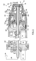
- a powder bell cup 30 is mounted on a turbine 40 of any of a number of known types.
- Powder bell cup 30 may be, for example, one of the general type illustrated and described in U. S. S. N. 10/262,239 filed September 30, 2002, titled Bell Cup Skirt, and assigned to the same assignee as this application.
- the disclosure of U. S. S. N. 10/262,239 is hereby incorporated herein by reference.
- Turbine 40 may be, for example, one of the general type illustrated and described in U. S. Patents 5,853,126 and 6,328,224. Turbine 40 rotates the cup 30 about the cup 30's axis 41.
- the source 44 may be one of any of a number of known types, for example, a fluidized bed of the general type illustrated and described in U. S. Patent 5,768,800.
- a high-magnitude potential source 54 is coupled to a final charging electrode 55 provided on the forward face 57 of the diffuser 34, that is, the face 57 facing generally toward an article 59 to be coated by the powder dispensed from the bell cup 30.
- the exposure of the streaming powder 42 to the charged electrode 55 results in charge being imparted upon the powder as the powder is being dispensed, with the result that the powder is attracted toward the article 59 which is maintained at low-magnitude, for example, ground, electrical potential.
- the article 59 is maintained at low-magnitude electrical potential by, for example, transporting the article 59 past the bell cup 30 on a grounded conveyor.
- the high-magnitude electrostatic potential supply 54 can be of any of a number of known types, for example, one of the general type illustrated and described in U. S. Patents 5,853,126 and 6,328,224.
- the power supply 54 is coupled through a high-magnitude potential conductor 61 and an electrically conductive component, for example, the metal housing, of the turbine 40 to, for example, the turbine 40's output shaft 56.
- Turbine 40's output shaft 56 is coupled to electrically conductive diffuser 34-mounting posts 32 through an electrically conductive component of the bell cup 30, such as its shaft 56-receiving sleeve 60.
- Sleeve 60 is provided with a flange 62 or the like including threaded openings 64 for receiving complementary threads on the posts 32.
- a cup 30 liner 68 of the general type described in U. S. Patents 5,853,126 and 6,328,224 is inserted into the bell cup 30.
- a plurality of posts 32 illustratively three, are inserted through openings provided therefor in liner 68 and threaded into openings provided for posts 32 in flange 62.
- the posts may be of the general type illustrated and described in U. S. S. N. 10/236,486 filed September 6, 2002, titled Bell Cup Post, and assigned to the same assignee as this application. The disclosure of U. S. S. N. 10/236,486 is hereby incorporated herein by reference.
- the forward ends of the posts 32 are provided with axial, threaded openings.
- the plate-like charging electrode 55 is located on the forward face 57 of the diffuser 34, and electrically conductive screws are threaded into the threaded openings in the forward ends of posts 32 to secure the diffuser 34 and electrode 55 to the bell cup 30 and electrically couple electrode 55 through posts 32, sleeve 60 and shaft 56 to supply 54.
- the posts 32 establish the width of the annular opening 36, support the diffuser 34 and the charging electrode 55 on the front of the diffuser 34, and provide a conductive path 61, 56, 60, 62, 32 from the high magnitude potential source 54 to the electrode 55, in order to charge the powder streaming through the annular opening 36.
- the turbine 40 is housed within a shroud 100.
- Shroud 100 is provided at its forward end 102 with an annular gallery 104.
- Gallery 104 is provided with a compressed gas or mixture of gases, for example, compressed air, from a source such as so-called "factory compressed air," turbine 40 exhaust air, or some combination of these and/or other source.
- the forward end 102 of the shroud 100 adjacent gallery 104 is provided with a number of perimetrally spaced passageways 108 between gallery 104 and the surface 110 of forward end 102.
- the compressed gas streaming from gallery 104 through these passageways 108 helps to shape the cloud of powder streaming from annular opening 36 and propel the powder in the cloud toward the article 59.
- Shroud 100 is also provided with a second high-magnitude potential conductor 111.
- Conductor 111 is coupled to conductor 61 intermediate supply 54 and the point at which conductor 61 makes contact with the turbine 40 housing. This coupling is achieved in the illustrated embodiment using a conductive adhesive, such as, for example, MetaDuct 1202 silver adhesive and cement available from Mereco Technologies Group, 1505 Main Street, West Warwick, Rhode Island 02893.
- Conductor 111 extends first radially outwardly and rearwardly within shroud 100 and then forward to a point at which conductor 111 contacts a first electrically conductive, for example, silver/glass-filled, natural or synthetic resin, hollow O-ring 112.
- O-ring 112 is housed in a groove 114 provided therefor at a junction 116 of two adjacent components 118, 120 of shroud 100.
- Conductor 122 extends forward from O-ring 112 through a passageway provided for conductor 122 in component 120 to a second electrically conductive, for example, silver/glass-filled, natural or synthetic resin, hollow O-ring 124 housed in a groove 126 provided therefor at a junction 126 of two components 120, 128 of shroud 100.
- O-rings 112, 124 illustratively are constructed from filled resins having Shore A hardness in the range of about 45 to 75 durometer, specific gravity of about 1.8, tensile strength of about 200 p. s. i.
- O-rings 112, 124 are of types available from, for example, Zatkoff Seals & Packings, 23230 Industrial Park Drive, Farmington Hills, Michigan 48335-2850.
- a plurality, illustratively fifteen, of equally angularly spaced, radially extending electrodes 130 extend between an electrically conductive, for example, bronze, electrode holder ring 131 mounted at junction 126 and a radially outer surface 132 of component 128.
- the radially inner ends of electrodes 130 are mounted in, and are therefore electrically connected to, ring 131.
- Ring 131 contacts O-ring 124 in the assembled shroud 100.
- This construction couples the high-magnitude potential provided by supply 54 not only to charging electrode 55 but also to electrodes 130, the radially outer ends of which are exposed at the surface 110 of shroud 100.
- Fig. 4 illustrates a comparison of the electrical field provided by the illustrated system with -50 KV supplied to charging electrode 55 but with electrodes 130 maintained at ground potential (in the lower half of Fig. 4), and the illustrated system with -50 KV supplied both to charging electrode 55 and to electrodes 130 (in the upper half of Fig. 4).
- the -10 KV equipotential lines 140 and the -40 KV equipotential lines 142 extend much farther from charging electrode 55 both forward, that is, toward article 59 to be coated, and rearward, that is, away from article 59 and toward any supporting structure for turbine 40, powder bell cup 30 and shroud 100.
- This field configuration is believed to promote transport of more of the electrically charged powder dispensed from powder bell cup 30 toward article 59, and the deposit of less of the electrically charged powder dispensed from powder bell cup 30 on, for example, the rearward portion of shroud 100 and any supporting structure.
Abstract
Description
Claims (10)
- A method of dispensing electrically charged particles of a coating material, the method including providing a source of the coating material, providing a supply of electrical charge, providing a dispenser for dispensing the charged particles of coating material, providing on the dispenser a first electrode, coupling the source of coating material to the dispenser, providing at least one second electrode at a location removed from the first electrode, and coupling both the first electrode and the at least one second electrode to the supply of electrical charge.
- The method of claim 1 further including providing a housing for housing the rotator, providing the rotator including providing a rotator having an output shaft for mounting the dispenser, providing on the housing an opening through which the output shaft is accessible to mount the dispenser, providing at least one second electrode including providing multiple second electrodes, and arraying the multiple second electrodes around an axis of rotation of the dispenser.
- Apparatus for dispensing electrically charged particles of a coating material, the apparatus including a port through which coating material is introduced, a terminal through which electrical charge is introduced, a dispenser for dispensing the charged particles of coating material, a first electrode provided on the dispenser, the port being coupled to the dispenser, and at least one second electrode at a location removed from the first electrode, both the first electrode and the at least one second electrode being coupled to the terminal.
- The apparatus of claim 3 further including a source of coating material for coupling to the port.
- The apparatus of claim 4 wherein the source comprises a fluidized bed in which the coating material is fluidized in a transporting medium and the dispenser comprises a dispenser for dispensing the coating material fluidized in the transporting medium.
- The apparatus of at least one of claims 3 to 5 wherein the dispenser includes a generally cup-shaped component having a perimetrally extending lip, the dispenser further including a diffuser component having a perimetrally extending lip, and a discharge region defined between the lips of the generally cup-shaped component and diffuser component.
- The apparatus of claim 6 wherein the first electrode is provided on the diffuser component.
- The apparatus of claim 7 wherein the diffuser component includes a first side facing generally toward the generally cup-shaped component and a second side facing generally away from the cup-shaped component, the first electrode provided on the second side of the diffuser component.
- The apparatus of at least one of claims 6 to 8 wherein the first electrode includes a perimetral lip adjacent to the perimetrally extending lip of the diffuser component.
- The apparatus of at least one of claims 3 to 9 further comprising a rotator for rotating the dispenser during dispensing of the coating material, a housing for housing the rotator, the rotator having an output shaft for mounting the dispenser, the housing including an opening through which the output shaft is accessible to mount the dispenser, the at least one second electrode including multiple second electrodes arrayed around an axis of rotation of the dispenser, both the first electrode and the multiple second electrodes being coupled to the terminal.
Applications Claiming Priority (2)
| Application Number | Priority Date | Filing Date | Title |
|---|---|---|---|
| US10/628,907 US7128277B2 (en) | 2003-07-29 | 2003-07-29 | Powder bell with secondary charging electrode |
| US628907 | 2003-07-29 |
Publications (2)
| Publication Number | Publication Date |
|---|---|
| EP1502655A2 true EP1502655A2 (en) | 2005-02-02 |
| EP1502655A3 EP1502655A3 (en) | 2007-11-21 |
Family
ID=33541467
Family Applications (1)
| Application Number | Title | Priority Date | Filing Date |
|---|---|---|---|
| EP04012056A Withdrawn EP1502655A3 (en) | 2003-07-29 | 2004-05-21 | Powder bell with secondary charging electrode |
Country Status (11)
| Country | Link |
|---|---|
| US (1) | US7128277B2 (en) |
| EP (1) | EP1502655A3 (en) |
| JP (1) | JP2005046842A (en) |
| KR (1) | KR20050013935A (en) |
| CN (1) | CN100484641C (en) |
| AU (1) | AU2004203447B2 (en) |
| CA (1) | CA2471068C (en) |
| MX (1) | MXPA04007378A (en) |
| NZ (1) | NZ534087A (en) |
| TW (1) | TWI268810B (en) |
| ZA (1) | ZA200403982B (en) |
Cited By (19)
| Publication number | Priority date | Publication date | Assignee | Title |
|---|---|---|---|---|
| EP1800757A1 (en) * | 2004-09-17 | 2007-06-27 | Toyota Jidosha Kabushiki Kaisha | Electrostatic coating system |
| EP1832348A1 (en) * | 2004-12-28 | 2007-09-12 | Ransburg Industrial Finishing KK | Electrostatic coater |
| US9415142B2 (en) | 2006-04-26 | 2016-08-16 | Micell Technologies, Inc. | Coatings containing multiple drugs |
| US9433516B2 (en) | 2007-04-17 | 2016-09-06 | Micell Technologies, Inc. | Stents having controlled elution |
| US9486431B2 (en) | 2008-07-17 | 2016-11-08 | Micell Technologies, Inc. | Drug delivery medical device |
| US9510856B2 (en) | 2008-07-17 | 2016-12-06 | Micell Technologies, Inc. | Drug delivery medical device |
| US9737642B2 (en) | 2007-01-08 | 2017-08-22 | Micell Technologies, Inc. | Stents having biodegradable layers |
| US9789233B2 (en) | 2008-04-17 | 2017-10-17 | Micell Technologies, Inc. | Stents having bioabsorbable layers |
| US9827117B2 (en) | 2005-07-15 | 2017-11-28 | Micell Technologies, Inc. | Polymer coatings containing drug powder of controlled morphology |
| US9981072B2 (en) | 2009-04-01 | 2018-05-29 | Micell Technologies, Inc. | Coated stents |
| US10117972B2 (en) | 2011-07-15 | 2018-11-06 | Micell Technologies, Inc. | Drug delivery medical device |
| US10188772B2 (en) | 2011-10-18 | 2019-01-29 | Micell Technologies, Inc. | Drug delivery medical device |
| US10232092B2 (en) | 2010-04-22 | 2019-03-19 | Micell Technologies, Inc. | Stents and other devices having extracellular matrix coating |
| US10272606B2 (en) | 2013-05-15 | 2019-04-30 | Micell Technologies, Inc. | Bioabsorbable biomedical implants |
| US10835396B2 (en) | 2005-07-15 | 2020-11-17 | Micell Technologies, Inc. | Stent with polymer coating containing amorphous rapamycin |
| US11039943B2 (en) | 2013-03-12 | 2021-06-22 | Micell Technologies, Inc. | Bioabsorbable biomedical implants |
| US11369498B2 (en) | 2010-02-02 | 2022-06-28 | MT Acquisition Holdings LLC | Stent and stent delivery system with improved deliverability |
| US11426494B2 (en) | 2007-01-08 | 2022-08-30 | MT Acquisition Holdings LLC | Stents having biodegradable layers |
| US11904118B2 (en) | 2010-07-16 | 2024-02-20 | Micell Medtech Inc. | Drug delivery medical device |
Families Citing this family (26)
| Publication number | Priority date | Publication date | Assignee | Title |
|---|---|---|---|---|
| US7793869B2 (en) * | 2003-08-18 | 2010-09-14 | Nordson Corporation | Particulate material applicator and pump |
| WO2005075091A1 (en) * | 2004-02-09 | 2005-08-18 | Matsushita Electric Works, Ltd. | Electrostatic spraying device |
| DE202006011299U1 (en) * | 2006-07-22 | 2007-11-29 | Wieland Electric Gmbh | Universal housing for a connector |
| WO2008052000A2 (en) | 2006-10-23 | 2008-05-02 | Micell Technologies, Inc. | Holder for electrically charging a substrate during coating |
| FR2915115B1 (en) * | 2007-04-23 | 2010-09-10 | Sames Technologies | SPRAYING DEVICE, PROJECTION DEVICE COMPRISING SUCH AN ORGAN, PROJECTION PLANT AND METHOD OF CLEANING SUCH AN ORGAN |
| US8371517B2 (en) | 2007-06-29 | 2013-02-12 | Illinois Tool Works Inc. | Powder gun deflector |
| US8602326B2 (en) * | 2007-07-03 | 2013-12-10 | David M. Seitz | Spray device having a parabolic flow surface |
| JP4964721B2 (en) * | 2007-09-20 | 2012-07-04 | 本田技研工業株式会社 | Painting equipment |
| US8096264B2 (en) | 2007-11-30 | 2012-01-17 | Illinois Tool Works Inc. | Repulsion ring |
| EP2213378B1 (en) * | 2007-11-30 | 2014-08-20 | Abb K.K. | Electrostatic coating device |
| US7988075B2 (en) | 2008-03-10 | 2011-08-02 | Illinois Tool Works Inc. | Circuit board configuration for air-powered electrostatically aided coating material atomizer |
| US8590817B2 (en) * | 2008-03-10 | 2013-11-26 | Illinois Tool Works Inc. | Sealed electrical source for air-powered electrostatic atomizing and dispensing device |
| US8770496B2 (en) | 2008-03-10 | 2014-07-08 | Finishing Brands Holdings Inc. | Circuit for displaying the relative voltage at the output electrode of an electrostatically aided coating material atomizer |
| US7926748B2 (en) * | 2008-03-10 | 2011-04-19 | Illinois Tool Works Inc. | Generator for air-powered electrostatically aided coating dispensing device |
| US8016213B2 (en) * | 2008-03-10 | 2011-09-13 | Illinois Tool Works Inc. | Controlling temperature in air-powered electrostatically aided coating material atomizer |
| US8496194B2 (en) | 2008-03-10 | 2013-07-30 | Finishing Brands Holdings Inc. | Method and apparatus for retaining highly torqued fittings in molded resin or polymer housing |
| US10155233B2 (en) * | 2008-04-09 | 2018-12-18 | Carlisle Fluid Technologies, Inc. | Splash plate retention method and apparatus |
| US7918409B2 (en) * | 2008-04-09 | 2011-04-05 | Illinois Tool Works Inc. | Multiple charging electrode |
| DE102009013979A1 (en) * | 2009-03-19 | 2010-09-23 | Dürr Systems GmbH | Electrode arrangement for an electrostatic atomizer |
| US8225968B2 (en) | 2009-05-12 | 2012-07-24 | Illinois Tool Works Inc. | Seal system for gear pumps |
| JP6242854B2 (en) | 2012-04-12 | 2017-12-06 | ノードソン コーポレーションNordson Corporation | Powder spray gun with wear-resistant electrode support |
| EP2872257B1 (en) * | 2012-07-16 | 2020-09-23 | Nordson Corporation | Powder gun configurable for supply from venturi or dense phase pump |
| CN106163673B (en) * | 2014-03-25 | 2018-11-13 | 本田技研工业株式会社 | Taic coating device |
| CA2966129C (en) * | 2014-10-27 | 2022-08-02 | Council Of Scientific & Industrial Research | Manually controlled variable coverage high range electrostatic sprayer |
| CN114134497B (en) * | 2021-11-30 | 2024-01-26 | 中冶京诚工程技术有限公司 | Nozzle for spraying powder and spraying device |
| DE102023114613A1 (en) * | 2022-06-03 | 2023-12-14 | P+S Pulverbeschichtungs- u. Staubfilteranlagen GmbH | Method for dispensing powder and powder spray nozzle for carrying out the method |
Citations (67)
| Publication number | Priority date | Publication date | Assignee | Title |
|---|---|---|---|---|
| US2759763A (en) | 1952-07-22 | 1956-08-21 | Ransburg Electro Coating Corp | Spray coating apparatus and method |
| US2955565A (en) | 1956-03-19 | 1960-10-11 | Electro Dispersion Corp | Electrostatic coating apparatus |
| FR1274814A (en) | 1960-11-05 | 1961-10-27 | Spray method and apparatus | |
| US3102062A (en) | 1960-03-28 | 1963-08-27 | Stratford Eng Corp | Apparatus for continuous edible oil finishing |
| US3233655A (en) | 1964-05-07 | 1966-02-08 | Stratford Eng Corp | Liquid atomization apparatus |
| GB1209653A (en) | 1968-07-02 | 1970-10-21 | Air O Static Inc | Apparatus for electrostatic spray coating |
| US3536514A (en) | 1963-06-13 | 1970-10-27 | Ransburg Electro Coating Corp | Electrostatic coating method |
| US3575344A (en) | 1969-09-22 | 1971-04-20 | Electrostatic Equip Corp | Nozzle and apparatus for electrostatic powder spraying |
| US3578997A (en) | 1968-10-21 | 1971-05-18 | Tunzini Sames | Electric generators |
| US3589607A (en) | 1969-05-28 | 1971-06-29 | Gourdine Systems Inc | Electrostatic spray gun having an adjustable spray material orifice |
| US3610528A (en) | 1968-11-14 | 1971-10-05 | Tunzini Sames | Spray guns |
| US3684174A (en) | 1970-06-11 | 1972-08-15 | Georg Wilhelm Bein | Rotating atomizer for electrostatic painting apparatus |
| US3698636A (en) | 1970-05-06 | 1972-10-17 | Graco Inc | Device for the electrostatic application of protective coatings with synthetic powders by the use of spray guns |
| US3843054A (en) | 1971-03-22 | 1974-10-22 | Ransburg Electro Coating Corp | Powder apparatus |
| US3913523A (en) | 1972-08-07 | 1975-10-21 | Ransburg Electro Coating Corp | Powder coating apparatus |
| US3964683A (en) | 1975-09-02 | 1976-06-22 | Champion Spark Plug Company | Electrostatic spray apparatus |
| US4039145A (en) | 1974-09-06 | 1977-08-02 | Air-Industrie | Electrostatic powdering nozzle |
| US4066041A (en) | 1975-04-11 | 1978-01-03 | Gema Ag Apparatebau | Apparatus for electrostatically applying coating material to articles and the like |
| US4135667A (en) | 1977-03-23 | 1979-01-23 | Hajtomuvek Es Festoberendezesek Gyara | Apparatus for the electrostatic coating of workpieces |
| US4169560A (en) | 1975-03-29 | 1979-10-02 | Elektrostatische Spritz-- und Beflockungsgesellschaft G.F. Vohringer GmbH | Electrostatic spray gun for powdered material |
| US4171100A (en) | 1976-11-10 | 1979-10-16 | Hajtomuvek Es Festoberendezesek Gyara | Electrostatic paint spraying apparatus |
| US4214708A (en) | 1977-12-20 | 1980-07-29 | Air Industrie | Electrostatic paint spray apparatus having rotary spray head with an air seal |
| US4215818A (en) | 1977-09-20 | 1980-08-05 | National Research Development Corporation | Induction charging electrostatic spraying device and method |
| US4216915A (en) | 1977-05-12 | 1980-08-12 | Kurt Baumann | Electrostatic powder spray gun |
| US4323197A (en) | 1980-02-18 | 1982-04-06 | Toyota Jidosha Kogyo Kabushiki Kaisha | Rotary type electrostatic spray painting device |
| US4350304A (en) | 1980-04-04 | 1982-09-21 | Toyota Jidosha Kogyo Kabushiki Kaisha | Rotary type electrostatic spray painting device |
| US4360155A (en) | 1979-12-21 | 1982-11-23 | G & R Electro-Powder Coating Corporation | Powder coating distributor |
| US4381079A (en) | 1980-11-03 | 1983-04-26 | Ransburg Corporation | Atomizing device motor |
| JPS58124560A (en) | 1982-01-19 | 1983-07-25 | Nippon Ranzubaagu Kk | Electrostatic painting apparatus |
| US4402991A (en) | 1980-02-15 | 1983-09-06 | Basf Farben & Fasern A.G. | Process and apparatus for electrostatically coating objects |
| US4422577A (en) | 1980-08-06 | 1983-12-27 | National Research Development Corporation | Electrostatic spraying |
| US4447008A (en) | 1980-11-03 | 1984-05-08 | Ransburg Corporation | Atomizing device motor |
| USRE31590E (en) | 1977-02-07 | 1984-05-29 | Ransburg Japan, Ltd. | Atomization in electrostatic coating |
| US4450785A (en) | 1980-02-15 | 1984-05-29 | Basf Farben +Fasern Ag | Apparatus for coating objects electrostatically |
| US4505430A (en) | 1982-11-22 | 1985-03-19 | Ransburg Corporation | Self-cleaning atomizer |
| USRE31867E (en) | 1978-02-13 | 1985-04-16 | Nordson Corporation | Electrostatic spray gun |
| US4518119A (en) | 1980-10-24 | 1985-05-21 | Hermann Behr & Sohn Gmbh & Co. | Sprayer |
| JPS6094166A (en) | 1983-10-27 | 1985-05-27 | Toyota Motor Corp | Electrostatic coating device using rotary atomization |
| US4520754A (en) | 1982-02-02 | 1985-06-04 | Lester Gange | Process and apparatus for electrostatic application of liquids or powders on substances or objects |
| JPS60151554A (en) | 1984-01-19 | 1985-08-09 | Hitachi Metals Ltd | Discriminating method of precipitation of pearlite |
| US4580727A (en) | 1982-06-03 | 1986-04-08 | Ransburg-Gema Ag | Atomizer for coating with powder |
| US4598870A (en) | 1983-08-25 | 1986-07-08 | Weitmann & Konrad Gmbh & Co. Kg | Device for the powder-dusting of moving objects, particularly flat substrates |
| JPS62140660A (en) | 1985-12-17 | 1987-06-24 | Asahi Okuma Ind Co Ltd | Rotary disk type electrostatic painter |
| US4685620A (en) | 1985-09-30 | 1987-08-11 | The University Of Georgia Research Foundation Inc. | Low-volume electrostatic spraying |
| US4726521A (en) | 1985-06-27 | 1988-02-23 | Bayer Aktiengesellschaft | Process for the production of electrically charged spray mist of conductive liquids |
| JPS63116776A (en) | 1986-10-31 | 1988-05-21 | Mazda Motor Corp | Method for supplying paint into rotary atomizing head of spray apparatus |
| US4779805A (en) | 1982-10-13 | 1988-10-25 | Imperial Chemical Industries Plc | Electrostatic sprayhead assembly |
| US4785995A (en) | 1986-03-18 | 1988-11-22 | Mazda Motor Corporation | Methods and apparatus for conducting electrostatic spray coating |
| US4788933A (en) | 1986-03-13 | 1988-12-06 | Ransburg-Gema Ag | Electrostatic spraying device for spraying articles with powdered material |
| US4798340A (en) | 1986-01-14 | 1989-01-17 | Esb Elektrostatische Spruh- Und Beschichtungsanlagen G.F. Vohringer Gmbh | Electrostatic device for powder spraying with triboelectric powder charging |
| US4802625A (en) | 1986-03-13 | 1989-02-07 | Ransburg-Gema Ag | Electrostatic spray coating device for coating with powder |
| US4825807A (en) | 1987-11-05 | 1989-05-02 | Nippon Steel Corporation | Apparatus for applying anti-sticking agent on annealed oriented electrical sheet steel in coil |
| US4879137A (en) | 1987-05-27 | 1989-11-07 | Behr Industrieanlagen Gmbh & Co. | Method and apparatus for electrostatic coating with conductive material |
| US4887770A (en) | 1986-04-18 | 1989-12-19 | Nordson Corporation | Electrostatic rotary atomizing liquid spray coating apparatus |
| JPH01315361A (en) | 1988-06-13 | 1989-12-20 | Toyota Motor Corp | Method and apparatus for rotary atomization electrostatic coating |
| US4890190A (en) | 1988-12-09 | 1989-12-26 | Graco Inc. | Method of selecting optimum series limiting resistance for high voltage control circuit |
| US4896384A (en) | 1986-11-27 | 1990-01-30 | Ucosan B.V. | Discharge nozzle for the discharge valve of a whirlpool tub |
| US4921172A (en) | 1987-02-12 | 1990-05-01 | Sames S.A. | Electrostatic sprayer device for spraying products in powder form |
| JPH03169361A (en) | 1989-11-30 | 1991-07-23 | Toyota Motor Corp | Rotary atomizing electrostatic painting machine |
| JPH03221166A (en) | 1990-01-27 | 1991-09-30 | Toyota Motor Corp | Rotary atomizing electrostatic painting machine |
| US5353995A (en) | 1992-06-10 | 1994-10-11 | Sames S.A. | Device with rotating ionizer head for electrostatically spraying a powder coating product |
| US5358182A (en) | 1992-06-22 | 1994-10-25 | Sames S.A. | Device with rotating atomizer head for electrostatically spraying liquid coating product |
| US5433387A (en) | 1992-12-03 | 1995-07-18 | Ransburg Corporation | Nonincendive rotary atomizer |
| US5720436A (en) | 1995-08-02 | 1998-02-24 | Gema Volstatic Ag | Electrostatic spray device for coating material |
| US5749529A (en) | 1994-07-29 | 1998-05-12 | Nissan Motor Co., Ltd. | Method of producing corona discharge and electrostatic painting system employing corona discharge |
| US5853126A (en) | 1997-02-05 | 1998-12-29 | Illinois Tool Works, Inc. | Quick disconnect for powder coating apparatus |
| US6328224B1 (en) | 1997-02-05 | 2001-12-11 | Illinois Tool Works Inc. | Replaceable liner for powder coating apparatus |
Family Cites Families (19)
| Publication number | Priority date | Publication date | Assignee | Title |
|---|---|---|---|---|
| US31867A (en) * | 1861-04-02 | Brake eor carriages | ||
| CH388317A (en) | 1959-11-17 | 1965-02-28 | Egyt Gyogyszervegyeszeti Gyar | Process for the preparation of N- (B-hydroxyethyl) -N '- (y- (3'-chloro-10'-phenothiazinyl) -propyl) -piperazine |
| JPS58190457U (en) | 1982-06-10 | 1983-12-17 | 富士写真フイルム株式会社 | electrostatic painting equipment |
| JPS62140669A (en) | 1985-12-13 | 1987-06-24 | Matsushita Electric Works Ltd | Resin coater for sealing electronic parts |
| FR2603210B1 (en) | 1986-08-28 | 1989-05-19 | Serole Bernard | GAS ATOMIZATION PIPE, COUPLED WITH AN ELECTRIC ARC OR A PLASMA. |
| JPH0694166A (en) | 1992-09-16 | 1994-04-05 | Nitta Moore Co Ltd | Attaching mechanism for member |
| DE4312262A1 (en) * | 1993-04-15 | 1994-10-20 | Gema Volstatic Ag | Electrostatic spray device |
| JPH0810659A (en) * | 1994-07-04 | 1996-01-16 | Abb Ransburg Kk | Rotational spraying type electrostatic coating apparatus |
| US5518546A (en) | 1994-10-05 | 1996-05-21 | Enexus Corporation | Apparatus for coating substrates with inductively charged resinous powder particles |
| US5647543A (en) | 1995-01-31 | 1997-07-15 | Graco Inc | Electrostatic ionizing system |
| WO1996036438A1 (en) * | 1995-05-19 | 1996-11-21 | Nordson Corporation | Powder spray gun with rotary distributor |
| US5768800A (en) * | 1995-06-08 | 1998-06-23 | Matsuo Sangyo Co. Ltd. | Powder feed mechanism |
| DE19537089A1 (en) * | 1995-10-05 | 1997-04-10 | Abb Research Ltd | Method and device for powder spraying |
| JP3322100B2 (en) | 1995-11-09 | 2002-09-09 | 日産自動車株式会社 | Rotary atomizing electrostatic coating equipment |
| JPH1057848A (en) | 1996-08-23 | 1998-03-03 | Toyota Motor Corp | Electrostatic coating apparatus |
| US5947377A (en) * | 1997-07-11 | 1999-09-07 | Nordson Corporation | Electrostatic rotary atomizing spray device with improved atomizer cup |
| JP3411815B2 (en) | 1998-03-26 | 2003-06-03 | Abb株式会社 | Rotary atomizing head type coating equipment |
| US6076751A (en) * | 1998-12-15 | 2000-06-20 | Illinois Tool Works Inc. | Method of charging using nonincendive rotary atomizer |
| US6793150B2 (en) * | 2002-06-03 | 2004-09-21 | Illinois Tool Works, Inc. | Bell cup post |
-
2003
- 2003-07-29 US US10/628,907 patent/US7128277B2/en not_active Expired - Fee Related
-
2004
- 2004-05-21 EP EP04012056A patent/EP1502655A3/en not_active Withdrawn
- 2004-05-21 ZA ZA200403982A patent/ZA200403982B/en unknown
- 2004-06-02 TW TW093115870A patent/TWI268810B/en not_active IP Right Cessation
- 2004-06-16 CA CA002471068A patent/CA2471068C/en not_active Expired - Fee Related
- 2004-07-13 NZ NZ534087A patent/NZ534087A/en unknown
- 2004-07-16 CN CNB2004100690889A patent/CN100484641C/en not_active Expired - Fee Related
- 2004-07-26 KR KR1020040058161A patent/KR20050013935A/en not_active Application Discontinuation
- 2004-07-28 AU AU2004203447A patent/AU2004203447B2/en not_active Ceased
- 2004-07-29 JP JP2004222086A patent/JP2005046842A/en active Pending
- 2004-07-29 MX MXPA04007378A patent/MXPA04007378A/en active IP Right Grant
Patent Citations (70)
| Publication number | Priority date | Publication date | Assignee | Title |
|---|---|---|---|---|
| US2759763A (en) | 1952-07-22 | 1956-08-21 | Ransburg Electro Coating Corp | Spray coating apparatus and method |
| US2955565A (en) | 1956-03-19 | 1960-10-11 | Electro Dispersion Corp | Electrostatic coating apparatus |
| US3102062A (en) | 1960-03-28 | 1963-08-27 | Stratford Eng Corp | Apparatus for continuous edible oil finishing |
| FR1274814A (en) | 1960-11-05 | 1961-10-27 | Spray method and apparatus | |
| US3536514A (en) | 1963-06-13 | 1970-10-27 | Ransburg Electro Coating Corp | Electrostatic coating method |
| US4114564A (en) | 1963-06-13 | 1978-09-19 | Ransburg Corporation | Electrostatic coating apparatus |
| US4037561A (en) | 1963-06-13 | 1977-07-26 | Ransburg Corporation | Electrostatic coating apparatus |
| US3233655A (en) | 1964-05-07 | 1966-02-08 | Stratford Eng Corp | Liquid atomization apparatus |
| GB1209653A (en) | 1968-07-02 | 1970-10-21 | Air O Static Inc | Apparatus for electrostatic spray coating |
| US3578997A (en) | 1968-10-21 | 1971-05-18 | Tunzini Sames | Electric generators |
| US3610528A (en) | 1968-11-14 | 1971-10-05 | Tunzini Sames | Spray guns |
| US3589607A (en) | 1969-05-28 | 1971-06-29 | Gourdine Systems Inc | Electrostatic spray gun having an adjustable spray material orifice |
| US3575344A (en) | 1969-09-22 | 1971-04-20 | Electrostatic Equip Corp | Nozzle and apparatus for electrostatic powder spraying |
| US3698636A (en) | 1970-05-06 | 1972-10-17 | Graco Inc | Device for the electrostatic application of protective coatings with synthetic powders by the use of spray guns |
| US3684174A (en) | 1970-06-11 | 1972-08-15 | Georg Wilhelm Bein | Rotating atomizer for electrostatic painting apparatus |
| US3843054A (en) | 1971-03-22 | 1974-10-22 | Ransburg Electro Coating Corp | Powder apparatus |
| US3913523A (en) | 1972-08-07 | 1975-10-21 | Ransburg Electro Coating Corp | Powder coating apparatus |
| US4039145A (en) | 1974-09-06 | 1977-08-02 | Air-Industrie | Electrostatic powdering nozzle |
| US4169560A (en) | 1975-03-29 | 1979-10-02 | Elektrostatische Spritz-- und Beflockungsgesellschaft G.F. Vohringer GmbH | Electrostatic spray gun for powdered material |
| US4066041A (en) | 1975-04-11 | 1978-01-03 | Gema Ag Apparatebau | Apparatus for electrostatically applying coating material to articles and the like |
| US3964683A (en) | 1975-09-02 | 1976-06-22 | Champion Spark Plug Company | Electrostatic spray apparatus |
| US4171100A (en) | 1976-11-10 | 1979-10-16 | Hajtomuvek Es Festoberendezesek Gyara | Electrostatic paint spraying apparatus |
| USRE31590E (en) | 1977-02-07 | 1984-05-29 | Ransburg Japan, Ltd. | Atomization in electrostatic coating |
| US4135667A (en) | 1977-03-23 | 1979-01-23 | Hajtomuvek Es Festoberendezesek Gyara | Apparatus for the electrostatic coating of workpieces |
| US4216915A (en) | 1977-05-12 | 1980-08-12 | Kurt Baumann | Electrostatic powder spray gun |
| US4215818A (en) | 1977-09-20 | 1980-08-05 | National Research Development Corporation | Induction charging electrostatic spraying device and method |
| US4214708A (en) | 1977-12-20 | 1980-07-29 | Air Industrie | Electrostatic paint spray apparatus having rotary spray head with an air seal |
| USRE31867E (en) | 1978-02-13 | 1985-04-16 | Nordson Corporation | Electrostatic spray gun |
| US4360155A (en) | 1979-12-21 | 1982-11-23 | G & R Electro-Powder Coating Corporation | Powder coating distributor |
| US4450785A (en) | 1980-02-15 | 1984-05-29 | Basf Farben +Fasern Ag | Apparatus for coating objects electrostatically |
| US4402991A (en) | 1980-02-15 | 1983-09-06 | Basf Farben & Fasern A.G. | Process and apparatus for electrostatically coating objects |
| US4323197A (en) | 1980-02-18 | 1982-04-06 | Toyota Jidosha Kogyo Kabushiki Kaisha | Rotary type electrostatic spray painting device |
| US4350304A (en) | 1980-04-04 | 1982-09-21 | Toyota Jidosha Kogyo Kabushiki Kaisha | Rotary type electrostatic spray painting device |
| US4422577A (en) | 1980-08-06 | 1983-12-27 | National Research Development Corporation | Electrostatic spraying |
| US4518119A (en) | 1980-10-24 | 1985-05-21 | Hermann Behr & Sohn Gmbh & Co. | Sprayer |
| US4381079A (en) | 1980-11-03 | 1983-04-26 | Ransburg Corporation | Atomizing device motor |
| US4447008A (en) | 1980-11-03 | 1984-05-08 | Ransburg Corporation | Atomizing device motor |
| JPS58124560A (en) | 1982-01-19 | 1983-07-25 | Nippon Ranzubaagu Kk | Electrostatic painting apparatus |
| US4520754A (en) | 1982-02-02 | 1985-06-04 | Lester Gange | Process and apparatus for electrostatic application of liquids or powders on substances or objects |
| US4580727A (en) | 1982-06-03 | 1986-04-08 | Ransburg-Gema Ag | Atomizer for coating with powder |
| US4779805A (en) | 1982-10-13 | 1988-10-25 | Imperial Chemical Industries Plc | Electrostatic sprayhead assembly |
| US4505430A (en) | 1982-11-22 | 1985-03-19 | Ransburg Corporation | Self-cleaning atomizer |
| US4598870A (en) | 1983-08-25 | 1986-07-08 | Weitmann & Konrad Gmbh & Co. Kg | Device for the powder-dusting of moving objects, particularly flat substrates |
| JPS6094166A (en) | 1983-10-27 | 1985-05-27 | Toyota Motor Corp | Electrostatic coating device using rotary atomization |
| JPS60151554A (en) | 1984-01-19 | 1985-08-09 | Hitachi Metals Ltd | Discriminating method of precipitation of pearlite |
| US4726521A (en) | 1985-06-27 | 1988-02-23 | Bayer Aktiengesellschaft | Process for the production of electrically charged spray mist of conductive liquids |
| US4685620A (en) | 1985-09-30 | 1987-08-11 | The University Of Georgia Research Foundation Inc. | Low-volume electrostatic spraying |
| JPS62140660A (en) | 1985-12-17 | 1987-06-24 | Asahi Okuma Ind Co Ltd | Rotary disk type electrostatic painter |
| US4798340A (en) | 1986-01-14 | 1989-01-17 | Esb Elektrostatische Spruh- Und Beschichtungsanlagen G.F. Vohringer Gmbh | Electrostatic device for powder spraying with triboelectric powder charging |
| US4788933A (en) | 1986-03-13 | 1988-12-06 | Ransburg-Gema Ag | Electrostatic spraying device for spraying articles with powdered material |
| US4802625A (en) | 1986-03-13 | 1989-02-07 | Ransburg-Gema Ag | Electrostatic spray coating device for coating with powder |
| US4785995A (en) | 1986-03-18 | 1988-11-22 | Mazda Motor Corporation | Methods and apparatus for conducting electrostatic spray coating |
| US4887770B1 (en) | 1986-04-18 | 1993-05-25 | Nordson Corp | |
| US4887770A (en) | 1986-04-18 | 1989-12-19 | Nordson Corporation | Electrostatic rotary atomizing liquid spray coating apparatus |
| JPS63116776A (en) | 1986-10-31 | 1988-05-21 | Mazda Motor Corp | Method for supplying paint into rotary atomizing head of spray apparatus |
| US4896384A (en) | 1986-11-27 | 1990-01-30 | Ucosan B.V. | Discharge nozzle for the discharge valve of a whirlpool tub |
| US4921172A (en) | 1987-02-12 | 1990-05-01 | Sames S.A. | Electrostatic sprayer device for spraying products in powder form |
| US4879137A (en) | 1987-05-27 | 1989-11-07 | Behr Industrieanlagen Gmbh & Co. | Method and apparatus for electrostatic coating with conductive material |
| US4825807A (en) | 1987-11-05 | 1989-05-02 | Nippon Steel Corporation | Apparatus for applying anti-sticking agent on annealed oriented electrical sheet steel in coil |
| JPH01315361A (en) | 1988-06-13 | 1989-12-20 | Toyota Motor Corp | Method and apparatus for rotary atomization electrostatic coating |
| US4890190A (en) | 1988-12-09 | 1989-12-26 | Graco Inc. | Method of selecting optimum series limiting resistance for high voltage control circuit |
| JPH03169361A (en) | 1989-11-30 | 1991-07-23 | Toyota Motor Corp | Rotary atomizing electrostatic painting machine |
| JPH03221166A (en) | 1990-01-27 | 1991-09-30 | Toyota Motor Corp | Rotary atomizing electrostatic painting machine |
| US5353995A (en) | 1992-06-10 | 1994-10-11 | Sames S.A. | Device with rotating ionizer head for electrostatically spraying a powder coating product |
| US5358182A (en) | 1992-06-22 | 1994-10-25 | Sames S.A. | Device with rotating atomizer head for electrostatically spraying liquid coating product |
| US5433387A (en) | 1992-12-03 | 1995-07-18 | Ransburg Corporation | Nonincendive rotary atomizer |
| US5749529A (en) | 1994-07-29 | 1998-05-12 | Nissan Motor Co., Ltd. | Method of producing corona discharge and electrostatic painting system employing corona discharge |
| US5720436A (en) | 1995-08-02 | 1998-02-24 | Gema Volstatic Ag | Electrostatic spray device for coating material |
| US5853126A (en) | 1997-02-05 | 1998-12-29 | Illinois Tool Works, Inc. | Quick disconnect for powder coating apparatus |
| US6328224B1 (en) | 1997-02-05 | 2001-12-11 | Illinois Tool Works Inc. | Replaceable liner for powder coating apparatus |
Cited By (36)
| Publication number | Priority date | Publication date | Assignee | Title |
|---|---|---|---|---|
| EP1800757A4 (en) * | 2004-09-17 | 2009-07-22 | Toyota Motor Co Ltd | Electrostatic coating system |
| US7966967B2 (en) | 2004-09-17 | 2011-06-28 | Toyota Jidosha Kabushiki Kaisha | Electrostatic coating system |
| EP1800757A1 (en) * | 2004-09-17 | 2007-06-27 | Toyota Jidosha Kabushiki Kaisha | Electrostatic coating system |
| EP1832348A1 (en) * | 2004-12-28 | 2007-09-12 | Ransburg Industrial Finishing KK | Electrostatic coater |
| EP1832348A4 (en) * | 2004-12-28 | 2008-11-05 | Ransburg Ind Finishing Kk | Electrostatic coater |
| US7784718B2 (en) | 2004-12-28 | 2010-08-31 | Ransburg Industrial Finishing K.K. | Electrostatic paint sprayer |
| US10898353B2 (en) | 2005-07-15 | 2021-01-26 | Micell Technologies, Inc. | Polymer coatings containing drug powder of controlled morphology |
| US10835396B2 (en) | 2005-07-15 | 2020-11-17 | Micell Technologies, Inc. | Stent with polymer coating containing amorphous rapamycin |
| US11911301B2 (en) | 2005-07-15 | 2024-02-27 | Micell Medtech Inc. | Polymer coatings containing drug powder of controlled morphology |
| US9827117B2 (en) | 2005-07-15 | 2017-11-28 | Micell Technologies, Inc. | Polymer coatings containing drug powder of controlled morphology |
| US11850333B2 (en) | 2006-04-26 | 2023-12-26 | Micell Medtech Inc. | Coatings containing multiple drugs |
| US9737645B2 (en) | 2006-04-26 | 2017-08-22 | Micell Technologies, Inc. | Coatings containing multiple drugs |
| US11007307B2 (en) | 2006-04-26 | 2021-05-18 | Micell Technologies, Inc. | Coatings containing multiple drugs |
| US9415142B2 (en) | 2006-04-26 | 2016-08-16 | Micell Technologies, Inc. | Coatings containing multiple drugs |
| US9737642B2 (en) | 2007-01-08 | 2017-08-22 | Micell Technologies, Inc. | Stents having biodegradable layers |
| US11426494B2 (en) | 2007-01-08 | 2022-08-30 | MT Acquisition Holdings LLC | Stents having biodegradable layers |
| US10617795B2 (en) | 2007-01-08 | 2020-04-14 | Micell Technologies, Inc. | Stents having biodegradable layers |
| US9486338B2 (en) | 2007-04-17 | 2016-11-08 | Micell Technologies, Inc. | Stents having controlled elution |
| US9433516B2 (en) | 2007-04-17 | 2016-09-06 | Micell Technologies, Inc. | Stents having controlled elution |
| US9775729B2 (en) | 2007-04-17 | 2017-10-03 | Micell Technologies, Inc. | Stents having controlled elution |
| US10350333B2 (en) | 2008-04-17 | 2019-07-16 | Micell Technologies, Inc. | Stents having bioabsorable layers |
| US9789233B2 (en) | 2008-04-17 | 2017-10-17 | Micell Technologies, Inc. | Stents having bioabsorbable layers |
| US9486431B2 (en) | 2008-07-17 | 2016-11-08 | Micell Technologies, Inc. | Drug delivery medical device |
| US9510856B2 (en) | 2008-07-17 | 2016-12-06 | Micell Technologies, Inc. | Drug delivery medical device |
| US10350391B2 (en) | 2008-07-17 | 2019-07-16 | Micell Technologies, Inc. | Drug delivery medical device |
| US9981071B2 (en) | 2008-07-17 | 2018-05-29 | Micell Technologies, Inc. | Drug delivery medical device |
| US9981072B2 (en) | 2009-04-01 | 2018-05-29 | Micell Technologies, Inc. | Coated stents |
| US10653820B2 (en) | 2009-04-01 | 2020-05-19 | Micell Technologies, Inc. | Coated stents |
| US11369498B2 (en) | 2010-02-02 | 2022-06-28 | MT Acquisition Holdings LLC | Stent and stent delivery system with improved deliverability |
| US10232092B2 (en) | 2010-04-22 | 2019-03-19 | Micell Technologies, Inc. | Stents and other devices having extracellular matrix coating |
| US11904118B2 (en) | 2010-07-16 | 2024-02-20 | Micell Medtech Inc. | Drug delivery medical device |
| US10729819B2 (en) | 2011-07-15 | 2020-08-04 | Micell Technologies, Inc. | Drug delivery medical device |
| US10117972B2 (en) | 2011-07-15 | 2018-11-06 | Micell Technologies, Inc. | Drug delivery medical device |
| US10188772B2 (en) | 2011-10-18 | 2019-01-29 | Micell Technologies, Inc. | Drug delivery medical device |
| US11039943B2 (en) | 2013-03-12 | 2021-06-22 | Micell Technologies, Inc. | Bioabsorbable biomedical implants |
| US10272606B2 (en) | 2013-05-15 | 2019-04-30 | Micell Technologies, Inc. | Bioabsorbable biomedical implants |
Also Published As
| Publication number | Publication date |
|---|---|
| US7128277B2 (en) | 2006-10-31 |
| TW200510070A (en) | 2005-03-16 |
| CA2471068A1 (en) | 2005-01-29 |
| CA2471068C (en) | 2008-02-19 |
| US20050023369A1 (en) | 2005-02-03 |
| KR20050013935A (en) | 2005-02-05 |
| CN1575860A (en) | 2005-02-09 |
| MXPA04007378A (en) | 2005-02-03 |
| NZ534087A (en) | 2005-04-29 |
| CN100484641C (en) | 2009-05-06 |
| AU2004203447A1 (en) | 2005-02-17 |
| AU2004203447B2 (en) | 2006-09-14 |
| JP2005046842A (en) | 2005-02-24 |
| TWI268810B (en) | 2006-12-21 |
| ZA200403982B (en) | 2005-06-13 |
| EP1502655A3 (en) | 2007-11-21 |
Similar Documents
| Publication | Publication Date | Title |
|---|---|---|
| US7128277B2 (en) | Powder bell with secondary charging electrode | |
| CA2192164C (en) | Rotary atomizing head type coating machine | |
| US4555058A (en) | Rotary atomizer coater | |
| US8096264B2 (en) | Repulsion ring | |
| JPH11505173A (en) | Powder spray gun with rotary distributor | |
| US4771949A (en) | Apparatus for electrostatic coating of objects | |
| US5163625A (en) | Electrostatic coating machine | |
| US6230993B1 (en) | Method of charging using nonincendive rotary atomizer | |
| US6889921B2 (en) | Bell cup skirt | |
| US6276618B1 (en) | Electrostatic powder spray gun | |
| US6676049B2 (en) | Bell cup powder spray applicator | |
| US6793150B2 (en) | Bell cup post | |
| JPH02503648A (en) | Spray coating equipment for conductive coating liquid | |
| US7520450B2 (en) | Electrical connections for coating material dispensing equipment | |
| US8888018B2 (en) | Powder gun deflector | |
| CA2479616A1 (en) | Split shroud for coating dispensing equipment | |
| SU1699633A1 (en) | Apparatus for electrostatically applying powder materials to inner pipe surfaces | |
| GB2354723A (en) | Electrostatic spray gun |
Legal Events
| Date | Code | Title | Description |
|---|---|---|---|
| PUAI | Public reference made under article 153(3) epc to a published international application that has entered the european phase |
Free format text: ORIGINAL CODE: 0009012 |
|
| 17P | Request for examination filed |
Effective date: 20040521 |
|
| AK | Designated contracting states |
Kind code of ref document: A2 Designated state(s): AT BE BG CH CY CZ DE DK EE ES FI FR GB GR HU IE IT LI LU MC NL PL PT RO SE SI SK TR |
|
| AX | Request for extension of the european patent |
Extension state: AL HR LT LV MK |
|
| PUAL | Search report despatched |
Free format text: ORIGINAL CODE: 0009013 |
|
| AK | Designated contracting states |
Kind code of ref document: A3 Designated state(s): AT BE BG CH CY CZ DE DK EE ES FI FR GB GR HU IE IT LI LU MC NL PL PT RO SE SI SK TR |
|
| AX | Request for extension of the european patent |
Extension state: AL HR LT LV MK |
|
| AKX | Designation fees paid |
Designated state(s): DE ES FR |
|
| 17Q | First examination report despatched |
Effective date: 20080905 |
|
| STAA | Information on the status of an ep patent application or granted ep patent |
Free format text: STATUS: THE APPLICATION IS DEEMED TO BE WITHDRAWN |
|
| 18D | Application deemed to be withdrawn |
Effective date: 20090924 |