EP1501727B1 - Automated food processing system and method - Google Patents
Automated food processing system and method Download PDFInfo
- Publication number
- EP1501727B1 EP1501727B1 EP03719850A EP03719850A EP1501727B1 EP 1501727 B1 EP1501727 B1 EP 1501727B1 EP 03719850 A EP03719850 A EP 03719850A EP 03719850 A EP03719850 A EP 03719850A EP 1501727 B1 EP1501727 B1 EP 1501727B1
- Authority
- EP
- European Patent Office
- Prior art keywords
- food
- container
- dispensing
- fry
- magazine
- Prior art date
- Legal status (The legal status is an assumption and is not a legal conclusion. Google has not performed a legal analysis and makes no representation as to the accuracy of the status listed.)
- Expired - Lifetime
Links
- 235000013305 food Nutrition 0.000 title claims abstract description 917
- 238000000034 method Methods 0.000 title claims abstract description 59
- 238000012545 processing Methods 0.000 title abstract description 38
- 230000007246 mechanism Effects 0.000 claims description 151
- 230000010006 flight Effects 0.000 claims description 34
- 238000005303 weighing Methods 0.000 claims description 22
- 241000287828 Gallus gallus Species 0.000 claims description 6
- 238000012544 monitoring process Methods 0.000 claims description 6
- 230000009977 dual effect Effects 0.000 claims description 5
- 241000251468 Actinopterygii Species 0.000 claims description 3
- 238000004806 packaging method and process Methods 0.000 description 140
- 235000012020 french fries Nutrition 0.000 description 128
- 239000008162 cooking oil Substances 0.000 description 69
- 235000011194 food seasoning agent Nutrition 0.000 description 61
- 230000033001 locomotion Effects 0.000 description 60
- 238000003860 storage Methods 0.000 description 54
- 230000006870 function Effects 0.000 description 21
- 238000010438 heat treatment Methods 0.000 description 20
- 239000000463 material Substances 0.000 description 18
- 230000000737 periodic effect Effects 0.000 description 18
- 239000003921 oil Substances 0.000 description 15
- 235000015228 chicken nuggets Nutrition 0.000 description 14
- 238000000151 deposition Methods 0.000 description 13
- 239000006260 foam Substances 0.000 description 12
- 150000003839 salts Chemical class 0.000 description 12
- 238000013519 translation Methods 0.000 description 12
- 239000002699 waste material Substances 0.000 description 11
- 230000009471 action Effects 0.000 description 10
- 238000010411 cooking Methods 0.000 description 10
- 230000036961 partial effect Effects 0.000 description 10
- 230000008569 process Effects 0.000 description 10
- 238000010276 construction Methods 0.000 description 9
- 230000000452 restraining effect Effects 0.000 description 9
- XLYOFNOQVPJJNP-UHFFFAOYSA-N water Chemical compound O XLYOFNOQVPJJNP-UHFFFAOYSA-N 0.000 description 9
- 239000002245 particle Substances 0.000 description 8
- 230000004888 barrier function Effects 0.000 description 7
- 230000005484 gravity Effects 0.000 description 7
- 238000002360 preparation method Methods 0.000 description 7
- 238000012546 transfer Methods 0.000 description 7
- 238000004519 manufacturing process Methods 0.000 description 6
- 230000002093 peripheral effect Effects 0.000 description 6
- 238000009938 salting Methods 0.000 description 6
- 238000013461 design Methods 0.000 description 5
- 230000000670 limiting effect Effects 0.000 description 5
- 230000000694 effects Effects 0.000 description 4
- 238000007710 freezing Methods 0.000 description 4
- 230000008014 freezing Effects 0.000 description 4
- 238000005057 refrigeration Methods 0.000 description 4
- 238000004088 simulation Methods 0.000 description 4
- 235000014676 Phragmites communis Nutrition 0.000 description 3
- WYTGDNHDOZPMIW-RCBQFDQVSA-N alstonine Natural products C1=CC2=C3C=CC=CC3=NC2=C2N1C[C@H]1[C@H](C)OC=C(C(=O)OC)[C@H]1C2 WYTGDNHDOZPMIW-RCBQFDQVSA-N 0.000 description 3
- 230000008859 change Effects 0.000 description 3
- 238000001816 cooling Methods 0.000 description 3
- 239000013078 crystal Substances 0.000 description 3
- 230000003247 decreasing effect Effects 0.000 description 3
- 238000009826 distribution Methods 0.000 description 3
- 238000005516 engineering process Methods 0.000 description 3
- 230000036541 health Effects 0.000 description 3
- 239000011810 insulating material Substances 0.000 description 3
- 230000003278 mimic effect Effects 0.000 description 3
- 230000008707 rearrangement Effects 0.000 description 3
- 230000000007 visual effect Effects 0.000 description 3
- 210000000707 wrist Anatomy 0.000 description 3
- 241000277284 Salvelinus fontinalis Species 0.000 description 2
- 230000004913 activation Effects 0.000 description 2
- 238000004364 calculation method Methods 0.000 description 2
- 238000004140 cleaning Methods 0.000 description 2
- 238000004891 communication Methods 0.000 description 2
- 230000001276 controlling effect Effects 0.000 description 2
- 230000001934 delay Effects 0.000 description 2
- 239000012774 insulation material Substances 0.000 description 2
- 238000012423 maintenance Methods 0.000 description 2
- 238000007726 management method Methods 0.000 description 2
- 238000012986 modification Methods 0.000 description 2
- 230000004048 modification Effects 0.000 description 2
- 230000003287 optical effect Effects 0.000 description 2
- 230000037361 pathway Effects 0.000 description 2
- 230000009467 reduction Effects 0.000 description 2
- 230000002829 reductive effect Effects 0.000 description 2
- 230000001105 regulatory effect Effects 0.000 description 2
- 230000008439 repair process Effects 0.000 description 2
- 230000004044 response Effects 0.000 description 2
- 239000000523 sample Substances 0.000 description 2
- 238000000926 separation method Methods 0.000 description 2
- 230000032258 transport Effects 0.000 description 2
- 238000011144 upstream manufacturing Methods 0.000 description 2
- 241000238557 Decapoda Species 0.000 description 1
- CWYNVVGOOAEACU-UHFFFAOYSA-N Fe2+ Chemical compound [Fe+2] CWYNVVGOOAEACU-UHFFFAOYSA-N 0.000 description 1
- 230000005355 Hall effect Effects 0.000 description 1
- 241001272720 Medialuna californiensis Species 0.000 description 1
- 229920006362 Teflon® Polymers 0.000 description 1
- 239000000919 ceramic Substances 0.000 description 1
- 235000013351 cheese Nutrition 0.000 description 1
- 238000006243 chemical reaction Methods 0.000 description 1
- 150000001875 compounds Chemical class 0.000 description 1
- 230000001419 dependent effect Effects 0.000 description 1
- 238000011161 development Methods 0.000 description 1
- 239000006185 dispersion Substances 0.000 description 1
- 235000013410 fast food Nutrition 0.000 description 1
- 239000012530 fluid Substances 0.000 description 1
- 238000005187 foaming Methods 0.000 description 1
- PCHJSUWPFVWCPO-UHFFFAOYSA-N gold Chemical compound [Au] PCHJSUWPFVWCPO-UHFFFAOYSA-N 0.000 description 1
- 239000010931 gold Substances 0.000 description 1
- 229910052737 gold Inorganic materials 0.000 description 1
- 239000004519 grease Substances 0.000 description 1
- 238000007654 immersion Methods 0.000 description 1
- 230000006872 improvement Effects 0.000 description 1
- 238000009434 installation Methods 0.000 description 1
- 238000009413 insulation Methods 0.000 description 1
- 239000002184 metal Substances 0.000 description 1
- 229910052751 metal Inorganic materials 0.000 description 1
- 239000007769 metal material Substances 0.000 description 1
- 239000000203 mixture Substances 0.000 description 1
- 239000011087 paperboard Substances 0.000 description 1
- 239000013618 particulate matter Substances 0.000 description 1
- 230000001737 promoting effect Effects 0.000 description 1
- 102000004169 proteins and genes Human genes 0.000 description 1
- 108090000623 proteins and genes Proteins 0.000 description 1
- 238000004064 recycling Methods 0.000 description 1
- 238000004904 shortening Methods 0.000 description 1
- 230000001360 synchronised effect Effects 0.000 description 1
- 230000036962 time dependent Effects 0.000 description 1
- 230000001960 triggered effect Effects 0.000 description 1
- 230000003313 weakening effect Effects 0.000 description 1
- 238000003466 welding Methods 0.000 description 1
Images


Classifications
-
- B—PERFORMING OPERATIONS; TRANSPORTING
- B65—CONVEYING; PACKING; STORING; HANDLING THIN OR FILAMENTARY MATERIAL
- B65B—MACHINES, APPARATUS OR DEVICES FOR, OR METHODS OF, PACKAGING ARTICLES OR MATERIALS; UNPACKING
- B65B43/00—Forming, feeding, opening or setting-up containers or receptacles in association with packaging
- B65B43/26—Opening or distending bags; Opening, erecting, or setting-up boxes, cartons, or carton blanks
- B65B43/30—Opening or distending bags; Opening, erecting, or setting-up boxes, cartons, or carton blanks by grippers engaging opposed walls, e.g. suction-operated
- B65B43/305—Opening or distending bags; Opening, erecting, or setting-up boxes, cartons, or carton blanks by grippers engaging opposed walls, e.g. suction-operated specially adapted for boxes, cartons or carton blanks
-
- A—HUMAN NECESSITIES
- A47—FURNITURE; DOMESTIC ARTICLES OR APPLIANCES; COFFEE MILLS; SPICE MILLS; SUCTION CLEANERS IN GENERAL
- A47J—KITCHEN EQUIPMENT; COFFEE MILLS; SPICE MILLS; APPARATUS FOR MAKING BEVERAGES
- A47J37/00—Baking; Roasting; Grilling; Frying
- A47J37/12—Deep fat fryers, e.g. for frying fish or chips
- A47J37/1228—Automatic machines for frying and dispensing metered amounts of food
Definitions
- the invention relates to automated food processing. More particularly, the invention relates to an automated food dispensing device for use in an automated food processing system for frying and packaging food into individual portion- sized containers such as at a quick-service type restaurant.
- Consistency in food preparation can vary as a result of many factors. For example, people engaged in food preparation often must perform multiple tasks at frequencies that vary with time because of constantly varying customer demand throughout the day. For example, lunchtime and dinnertime may be extremely busy while other periods may be relatively slow. The product mix can vary from hour to hour and day to day. As a result, the consistency and quality of food may vary. Difficulties in proper scheduling of food production during peak and non-peak periods can cause customer delays and/or stale, wasted or unusable food.
- Food preparation can be labor intensive, and thus, the labor cost can be a large portion of the total cost of the prepared food.
- An additional problem is that in sparsely populated and other areas where quick service restaurants are located, such as along interstate highways, for example, recruiting sufficient numbers of suitable employees is difficult.
- Patent FR 2597319 describes an apparatus for the automatic preparation and distribution of fried foodstuffs, particularly French fries.
- the present invention provides an automated dispensing device for dispensing a quantity of food pieces to be cooked comprising: a freezer; a food magazine located in the freezer for containing a plurality of food pieces to be dispensed, a secondary container located within the freezer for containing a plurality of food pieces dispensed from the food magazine; said food magazine having dual rotatable spiral flights, said spiral flights having a spacing of a size and shape to allow only one individual food piece to be placed in the spacing between adjacent flight segments and being rotatable to dispense individual pieces of food one piece at a time from the plurality of food pieces contained in the food magazine into the secondary container; means for dispensing a predetermined quantity of food from the food magazine into the secondary container, said means for dispensing being located in the freezer; a device for determining the quantity of food pieces contained in the secondary container and for terminating the dispensing of individual pieces of food from said food magazine when a predetermined quantity of food pieces is sensed in the secondary container; and means for dispensing the quantity of food
- the present invention further provides an automated method of dispensing a quantity of individual food pieces to be cooked comprising:
- the automated food processing system and method are described which allow food to be dispensed, fried and packaged in a suitable container or alternatively dispensed to a food holding area for subsequent processing by a human operator.
- an automated module system for dispensing, frying and packaging food into individual portion-sized containers is provided.
- the system includes an automated dispensing module capable of dispensing a desired quantity of food to be fried, an automated fry module adjacent the dispensing module to receive and fry the quantity of food dispensed from the dispensing module and to produce and dispense a quantity of fried food and an automated packaging module adjacent the fry module to receive and package the fried food from the fry module into an individual portion-sized container.
- the three modules are independent from each other and can be operated independently. Plus, in one embodiment, any one of the modules can be deactivated and a human operator can manually perform the function of the deactivated module with manually operated equipment.
- an automated seasoning device is present to apply seasoning to the food.
- the automated dispensing module in one embodiment is capable of dispensing one or more of uncooked or unheated French fries, chicken nuggets, hash browns, chicken patties and fish filets or similar types of food items to be cooked and/or heated.
- a fry module of the automated modular system may include a fry vat for containing and heating cooking oil, at least one circular fry wheel having at least a generally circular perimeter in a plurality of compartments, each compartment having an opening towards the perimeter, the fry wheel mounted for rotational movement relative to the radial axis of the fry wheel, which radial axis is disposed above the normal operating level of the frying oil or the cooking oil in the fry vat.
- a drive mechanism is provided for rotating the fry wheel. Any suitable type of automated fry device can be utilized.
- a control system may be provided for causing the drive mechanism to periodically rotate the fry wheel back and forth through a relatively small amount of angular rotation (such as about 2-10°, for example) to simulate shaking of a fry basket
- angular rotation such as about 2-10°, for example
- Food may be delivered from the fry module to a cooked food holding device, which can comprise a heated holding bin or bins.
- an automated packaging module includes a rotatable food dispensing member having an inlet location to receive a quantity of cooked food at a discharge location to discharge cooked food, the packaging module also including a food dispensing chute position to receive cooked food from the discharge location of the rotatable food dispenser, the food dispensing chute having a discharge location.
- the automated modular system further includes a carton holding device for holding the individual portion-sized carton or container in position to receive food from the discharge location of the dispensing chute.
- the packaging module may further include a rotatable food collecting member disposed to collect food from the discharge location of a dispensing chute that is not deposited into the individual portion-sized food container. The so collected food may be subsequently deposited into the food dispensing chute for delivery to a container or alternatively to the rotatable food dispensing member or to a waste receptacle or chute.
- the automated packaging device includes a conveyor system for transporting filled individual portion-sized food containers from adjacent the filling location to a filled food container holding area, for subsequent pick-up by a human operator, for example.
- a conveyor system for transporting filled individual portion-sized food containers from adjacent the filling location to a filled food container holding area, for subsequent pick-up by a human operator, for example.
- any suitable automated packaging device can be utilized.
- an automated food carton-retrieving device for retrieving and grasping individual portion-sized food containers.
- the automated retrieving device comprises a movable member for selectively grasping and releasing the food container.
- the retrieving device is capable of grasping and releasing an unerected food container on one side and the device further includes a second device for selectively grasping the unerected food container on the other side with structure for moving the retrieving device and the second device relatively apart when grasping the sides of the container to erect or partially erect the container.
- an automated is provided for urging the container bottom upwardly relative to the sides of the container when the sides of the container are moved relatively apart.
- the automated modular system includes an electronic control system that receives current customer order information and the electronic control system causes the selection of a container from a plurality of different container sizes and further causes filling of food with the size of food container in response to a customer order.
- the electronic control system can receive customer order information and controls the dispensing rate of food dispensed from the food dispensing module to the fry module which dispensing automatically determines the amount of food being fried without further intervention by the electronic control.
- the control system can include a separate control system for each of the dispensing, fry and packaging systems or modules, each of which interface with a central control system, which in turn optionally interfaces with a POS (point-of-sale) system.
- the automated modular system is suitable for dispensing, frying and packaging French fries into individual portion-sized containers.
- an automated method of dispensing, frying and packaging food into individual portion-sized containers includes dispensing a desired quantity portion of food to be fried from an automated dispensing module to an automated fry module and thereafter frying the portion of food dispensed from the dispensing module in the automated fry module adjacent the dispensing module to produce a quantity of fried food. Thereafter, the quantity of fried food is dispensed from the fry module to a packaging module where the fried food dispensed from the fry module is packaged into individual portion-sized containers with an automated packaging module.
- the automated method further comprises seasoning the quantity of fried food with a seasoning device.
- frying comprises a rotating fry wheel having at least a generally circular perimeter and a plurality of compartments, each compartment having an opening towards the perimeter, the food being contained in at least one of the compartments during the frying, the fry wheel being mounted for rotational movement relative to the radial axis of the fry wheel in a fry vat with the radial axis being disposed above a normal operating level of the cooking oil in the fry vat.
- the automated method further includes containing a drive mechanism to periodically rotate the fry wheel back and forth through a relatively small amount of angular rotation to simulate shaking of a fry basket during frying.
- packaging includes rotating a rotatable food dispensing member having an inlet location to receive a quantity of cooked food in a discharge location to discharge cooked food, the food dispensing member being rotated to dispense food into a food dispensing chute position to receive cooked food from the discharge location of the rotatable food dispenser and thereafter dispensing said food from the dispensing chute to a container to be filled.
- the method further includes holding an individual portion-sized carton or container positioned to receive food from the dispensing chute with an automated carton holding device.
- the method further includes collecting food dispensed from the discharge location of the dispensing chute that is not deposited into the individual portion-sized food container with a rotatable food collecting member disposed to collect such not deposited food.
- the method includes electronically coordinating the operation of the three modules or devices within an electronic control system.
- the method may further include electronically receiving current customer order information by the electronic control system which causes selection of a container from a plurality of different sized containers and filling the container with food of the ordered size of food container in response to a customer order by the packaging module.
- customer order information is electronically received and the dispensing rate of food dispensed from the food dispensing module to the fry module is controlled, which dispensing automatically determines the amount of food being fried without further intervention by the electronic control system.
- the means for dispensing a quantity of food includes a vibratory conveyor typically located in the freezer below the storage container.
- the structure for dispensing may further include a device for determining or sensing the quantity of food that has been deposited in the secondary container and structure is provided for terminating the operation of the structure for dispensing when a predetermined quantity of food is sensed in the secondary container
- the secondary container has a bottom that is at least partially open and the secondary container is movable laterally between a filling position located within the freezer and a dispensing position for dispensing food through the container open bottom and out of the freezer.
- the secondary container may include a floor member that is located below the container having the at least partially open bottom. The floor member and the container are movable relative to each other between the first and second positions wherein in the first position the floor member is adjacent the open bottom and prevents food from being dispensed from the container and when in the second position food is free to fall through the open bottom of the container.
- the device for determining the quantity may be on a volume or weight basis and thus can be a weighing mechanism, which can be a load cell.
- a device is provided for moving the second container laterally sufficiently to the dispensing position so that food contained therein is dispensed.
- a device may be, for example, a suitable actuator, which can be an air or hydraulic cylinder, for example.
- the automated dispensing device further includes a door that is located over an opening in the freezer compartment and positioned relative to the secondary container so that when the secondary container is moved laterally to the dispensing position, the food in the secondary container exits the freezer compartment through the open bottom and through the freezer compartment opening. Typically, the dispensed food will then be directed into the fry module.
- a vibratory conveyor for conveying food items to the secondary container.
- the vibratory conveyor in one embodiment may have a serpentine or a zigzag food travel pathway.
- a tray for vibratory conveying of food articles from a hopper may include a tray body, a food inlet portion and a food outlet portion, the food inlet including an upwardly extending dividing member for dividing the tray into at least two food inlet conveyor passageways, the inlet conveyor passageways merging into a single food passageway that extends to the food outlet portion after which the food passing therethrough is dispensed into the secondary container.
- the single food passageway may be nonlinear and may have a zigzag or a serpentine pathway or configuration.
- the dividing member of the tray for vibratory conveying of food articles is saddle-shaped.
- the tray for vibratory conveyance of food articles can be configured and dimensioned so that the single food passageway causes food of a particular size, such as the size of chicken nuggets, for example, to be conveyed in a single file arrangement.
- This allows for a precise vibratory dispensing of the food articles permitting them to be dispensed one at a time from the vibratory conveyor to the secondary container.
- Such an arrangement permits accurate metering of the food articles and precise control of the batch sizes that are cooked and subsequently packaged and served to customers. This permits more economical and efficient and reproducible operations.
- the vibratory conveyor includes a tray that has a bottom portion with a plurality of spaced apart holes to permit relatively small undesirable particles, such as ice particles and small particles of food to pass therethrough so that such material is not dispensed into the secondary container.
- the holes will be less than about 0.25 inches in diameter and can be located in a suitable array as desired.
- a generally vertically extending declumping member that can interact with food contained in the vibrating conveyor.
- the declumping member is in the form of a cylindrical member or pin that extends generally vertically towards the vibrating conveyor from a position located above the vibrating conveyor.
- the declumping member will be stationary relative to the vibrating conveyor so that as food, in particular, such as French fries, pass the declumping member as they travel along the vibrating conveyor clumps of French fries can be separated into smaller clumps or individual French fries. This facilitates the subsequent frying of such food materials.
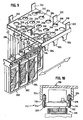
- the food magazine comprises dual rotatable spiral flights with the spiral flights having a spacing therebetween to allow placement of a food item, such as a chicken patty, for example, to be supported by both spiral flights.
- the food magazine is suspended from a slide mechanism permitting removal of the magazine from the freezer or refrigerated compartment
- a plurality of the magazines can be located on a single slide mechanism.
- An array of the magazines may be located in the freezer, such as a 3x5 array or a 3x4 array, for example.
- a separate drive motor is associated with each food dispensing magazine for selectively rotating spiral flights of a magazine dispenser for dispensing a desired number of the food items.
- the drive motor may also be located in the freezer.
- the secondary container with the at least partially open bottom moves relative to the floor member that remains stationary.
- a device for the automated frying of foods may include a fry vat for containing and heating cooking oil, at least one circular fry wheel having at least a generally circular perimeter and a plurality of compartments with each compartment having an opening towards the perimeter, the fry wheel mounted for rotational movement relative to the radial axis of the fry wheel which radial axis is disposed above the normal operating level of the frying oil in the fry vat.
- a drive mechanism is provided for rotating the fry wheel and a control system is included for causing the drive mechanism to periodically rotate the fry wheel back and forth through a relatively small amount of rotation (such as about 2-10°, for example) to simulate shaking of a fry basket.
- Such control can be accomplished electronically by devices known to those skilled in the art.
- the small amount of rotation may be in the range of from about 2° to about 20°.
- the back and forth rotation in one direction may be of a larger angle or amount of rotation than of the rotation in the other direction.
- a control system causes periodic incremental rotation of the fry wheel in one direction to cause food deposited into one of the compartments to travel through the cooking oil in the fry vat over a period of time to fry the food and to move the compartments out of the cooking oil for subsequent discharge of the food from the compartment.
- the periodic incremental rotation is based on 360° divided by the number of compartments in the fry wheel.
- a control system for operating the drive mechanism to rotate the fry wheel in one direction to cause food deposited into one of the compartments to travel through the cooking oil in the fry vat over a period of time to fry the food and out of the cooking oil for subsequent discharge of the food from the compartment, wherein the control system adjusts the speed of rotation based on the level of cooking oil in the fry vat.
- the control system causes incremental periodic rotation of the fry wheel and the control system adjusts the period of time between incremental rotations based on the level of cooking oil sensed in the fry vat. The period of time between incremental rotations can also be based on the temperature of the cooking oil in the fry vat.
- a curved baffle may be provided that is disposed in the fry vat adjacent the axial periphery of the portion of the fry wheel that is disposed in the cooking oil for preventing food contained in one or more of the fry wheel compartments from falling out of the compartments.
- a device for the automated frying of food includes a fry vat for containing and heating cooking oil, at least one circular fry wheel having at least a generally circular perimeter and a plurality of compartments each having an opening towards the perimeter, the fry wheel mounted for rotational movement relative to the radial axis of the wheel which radial axis is disposed above the normal operating level of the frying oil in the fry vat, a drive mechanism for rotating the fry wheel and an overflow passageway having an inlet that is located above the normal operating level of the frying oil in the fry vat.
- the overflow passageway is located in a foam deck that is adjacent a side of the fry vat.
- the foam deck has a surface located above the normal operating level of the frying oil in the fry vat.
- the overflow passageway comprises an elongated slot in the foam deck.
- the foam deck is preferably located adjacent or in proximity to the food inlet location for supplying a quantity of food to be fried in the fry wheel.
- an automated method of frying food in a fry vat having a heated cooking oil contained therein includes placing food in a fry wheel compartment, each of the compartments having an opening towards the perimeter of the fry wheel, rotating the fry wheel so that the compartment containing the food travels submerged in the heated cooking oil and periodically rotating the fry wheel back and forth in a relatively small amount of rotation to simulate shaking of the fry basket while the food is submerged in the cooking oil.
- the method may comprise rotating the fry wheel in one direction to cause the food deposited into one of the compartments to travel through the cooking oil in the fry vat over a period of time to fry the food and to move the food out of the cooking oil for subsequent discharge of the food from the compartment, wherein the speed of said rotating is related to the level of cooking oil in the fry vat.
- the rotating may comprise incremental periodic rotation with the period of time between incremental periodic rotations being based on the level of cooking oil sensed in the fry vat.
- the period of time between incremental periodic rotations may also be based on the temperature of the cooking oil in the fry vat.
- an automated method of frying food includes placing food to be fried in a fry wheel compartment of a fry wheel having at least a generally circular perimeter and a plurality of compartments, each having an opening towards the perimeter, the fry wheel mounted for rotational movement relative to the radial axis of the wheel which radial axis is disposed above the normal operating level of the frying oil in a fry vat having heated cooking oil therein, providing an overflow passageway having an inlet that is located above the normal operating level of the frying oil in the fry vat, collecting in the overflow passageway at least some of the water containing foam that results when food to be fried and placed in the fry wheel contacts the frying oil and rotating the fry wheel so that the compartment containing the food travels submerged in the heated cooking oil.
- the method may further include periodically rotating the fry wheel back and forth with a relatively small amount of rotation to simulate shaking of a fry basket while food is submerged in the cooking oil.
- an automated method of packaging cooked food which may be food such as French fries, chicken nuggets and other types of food, in an individual portion-sized container.
- the method includes delivering a quantity of a cooked food to a rotatable dispensing member, rotating the dispensing member to cause the food items to fall from one or more compartments of the dispensing member into a food dispensing chute and thereafter dispensing the food from the chute and depositing the food into the individual portion-sized food container.
- the method may further include weighing the food in the chute before dispensing the food to the container.
- the method may include applying seasoning to the food and may further include applying the seasoning by using gravity to cause the seasoning to travel through a nozzle and onto the food.
- the method may further include shaking the individual portion-sized food container after the dispensing.
- the shaking may be automated and can include back and forth movement of the container through an arc as desired, and may be in a generally vertical axis.
- the arc may be a generally circular arc and the rotating back and forth may encompass an arc in the range of from about 3° to about 20°.
- the container may be raised and lowered before, during or after the rotating to further simulate shaking or in connection with further container handling.
- the method may further include collecting the not deposited food.
- the not deposited food will be collected in a collection device that returns the not deposited food to the chute for subsequent dispensing.
- the collection member may be rotatable and can be rotated to deposit the collected food to the chute. This helps to ensure that the not deposited food is subsequently deposited into a container on a first-in, first-out or a generally first-in, first-out basis.
- the selected individual portion-sized container is moved by the automated device to a location for receiving food from the dispensing chute and food is dispensed from the chute and into the container.
- the method may further include depositing the filled food container onto a conveyor by operation of the automated device and transporting the deposited container by the conveyor to a human operator food pickup location.
- the individual portion-sized food container may be unerected and the method may further include after the selecting, erecting the selected individual portion-sized food container by the automated device.
- the automated device may include a partial vacuum suction device for holding the individual portion-sized food container and the holding includes applying a partial vacuum through a suction device to the food container.
- the food container can be released by reducing or eliminating the vacuum applied by the suction device to the food container sufficiently to cause the food container to be disengaged from the automated device.
- the filled food container may be placed in an upright position on a transportable member or container-receiving receptacle which in one embodiment contains a single food container and is maintained in an upright position on the transportable member by cooperation of the recessed volume of the transportable member and the food container.
- the transporting may be performed by a magnetic conveyor.
- An automated method of packaging cooked French fries in individual portion-sized French fry containers includes delivering with a mechanical device cooked French fries to a French fry holding bin and mechanically scooping with a mechanical device an open French fry container into the cooked French fries in the holding bin to fill the French fry container with French fries. After filling the French fry container, the method further includes mechanically depositing the filled French fry container at a drop-off location.
- the drop-off location will include a location that is convenient for a human operator to access the filled French fry containers for subsequent service to a customer.
- the delivering of cooked French fries to a French fry holding bin will be accomplished by receiving the French fries from an inlet chute which chute is traversed by the French fries prior to entering the French fry holding bin.
- the French fries enter the inlet chute after being dispensed from the fry module or other arrangement.
- the automated method of packaging cooked French fries may further include applying seasoning to the French fries which may occur while on the inlet chute.
- seasoning is preferably done by an automated system which may include a seasoning device or a salting device as hereafter described in detail.
- the inlet chute may include structure for vibrating the inlet chute to facilitate transport of French fries down the inlet chute.
- the inlet chute includes a first gate that is movable to a position that restrains the French fries from travelling down the chute. This provides a convenient time during which to apply the desired seasoning to the French fries.
- the gate may include a plurality of reciprocable fingers that are configured for up and down movement. The fingers may be configured such that in a retracted position the fingers do not extend above the surface of the inlet chute and in an extended position the fingers extend outwardly above the surface of the inlet chute sufficiently to prevent the passage of French fries.
- the fingers are periodically reciprocable in an up and down direction so that the fingers have a declumping action on French fries passing through the chute at the location of the reciprocable fingers.
- the method may include further restraining the French fries from exiting the inlet chute at a location downstream of the gate after passing the first gate.
- the further restraining can be performed by a second gate located downstream of the first gate.
- the second gate will be located downstream of the first gate a sufficient distance so that a desired quantity of French fries can be stored on the chute between the first and second gates.
- the second gate can be moved to a position that does not restrain the French fries so that the French fries are free to travel into the holding bin.
- An automated method of packaging cooked French fries may further include mechanically shaking the filled individual portion-sized French fry container prior to the depositing.
- the shaking may include back and forth movement through an arc in which the end-of-arm tool of the mechanical device travels, thereby causing the filled individual portion-sized French fry container to travel in that arc which can be any generally vertical axis.
- the mechanical device is a mechanical arm which can perform the mechanical scooping, shaking and depositing steps as desired.
- the method may further include holding the individual portion-sized French fry container with a mechanical arm of the mechanical device while performing the scooping, shaking and/or depositing. The shaking may be accomplished by up and down vertical movement of the mechanical arm.
- the method may further include mechanically obtaining an unerected individual portion-sized French fry container to be filled from a stack of unerected individual portion-sized French fry containers.
- the method can still further include mechanically erecting the unerected individual portion-sized French fry container prior to the scooping.
- the method may further include, before the obtaining of the unerected carton, selecting and holding with the mechanical device an individual portion-sized container of a desired size from a plurality of different sizes of individual portion-sized containers that can be selected and held by the automated device.
- a method of erecting a collapsed, individual portion-sized French fry container of the type having opposed sidewalls connected by a collapsible container bottom may be provided.
- the method includes grasping the unerected French fry container, pulling the container against a restraining member and mechanically dragging the bottom of the container so that it traverses up an inclined ramp to urge up the container bottom to urge the container to an erected position.
- the method may further include injecting a stream of compressed air into the open end of the container and towards the container bottom for assisting in the erecting.
- fill or “filled” is not limited to completely filling or a completely filled container and thus includes partially filling or partially filled containers.
- An automated device for packaging cooked food into a desired container which may be an individual portion-sized food container may be provided which device includes a rotatable food dispensing member having an inlet location to receive a quantity of the cooked food and a discharge location to discharge the cooked food.
- a food dispensing chute is positioned to receive the cooked food from the discharge location of the rotatable food dispenser and the dispensing chute has a discharge location.
- the dispensing chute has a food holding area for holding a quantity of the cooked food deposited therein.
- a suitable weighing device can be associated with the dispensing chute to weigh the food that is contained in the chute or in the holding area of the chute.
- the weighing device is a load cell.
- the automated device may include a food carton or container holding device for holding the food carton in position to receive food from the discharge location of the dispensing chute.
- the carton holding device can include an axially rotatable generally vertically extending elongated first member and a second member that extends from the elongated member, the second member having a gripping member for gripping a food container, which may be an individual portion-sized food container.
- the gripping member comprises a suction cup.
- a vacuum source may be supplied to the suction cup to create at least a partial vacuum, allowing the container to be held.
- the carton holding device is capable of moving the food container through an arc of about or of at least about 180° and in which the carton holding device is capable of moving the food container up and down.
- the automated device may comprise a conveyor system for transporting filled individual portion-sized food containers from adjacent the filling location to a filled container holding area.
- the conveyor system may comprise in one example a continuous loop raceway and a plurality of discrete movable food container receptacles that are movable along the raceway.
- the conveyor system may include a continuous movable loop having at least one magnetic element capable of magnetically attracting one of the movable receptacles at a time for causing movement of the receptacle corresponding to movement of the magnetic element.
- a plurality of the magnetic elements may be spaced apart along the movable loop.
- structure for preventing movement of the discrete receptacles when the structure for moving the discrete receptacles along the raceway is activated.
- the structure for preventing movement can be a barrier that is disposed across the raceway.
- the barrier is selectively movable and in another example the barrier is fixed.
- the barrier prevents movement of the receptacles only for a receptacle that has a food carton or container disposed thereon.
- the barrier may be located at a height that is above the top of the receptacles located on the conveyor system adjacent the barrier.
- An automated device may be provided to retrieve and grasp a food container, which may be an individual portion-sized food or French fry container or carton.
- the automated retrieving device includes a member for selectively grasping and releasing the food container and for moving the movable member horizontally and linearly.
- a magazine may be provided for holding a plurality of food containers in an unerected state.
- the automated device may include a retrieving device that is capable of grasping and releasing an unerected food container on one side and further includes a second device for selectively grasping the unerected food container on the other side.
- a structure for moving the retrieving device and the second device relatively apart when grasping the sides of the container is provided.
- the automated device may further include an automated urging means for urging the container bottom upwardly relative to the sides of the container when the retrieving device and the second device are moved relatively apart when grasping the container.
- the packaging device may also include an automated seasoning device for depositing a predetermined quantity of seasoning to food contained in the packaging device.
- the device for applying seasoning includes a seasoning delivery tube having an inlet and a discharge location.
- a seasoning delivery head is positioned to deliver seasoning to the food to be seasoned with the head in communication with the outlet of the delivery tube and located below the inlet of the delivery tube.
- Structure is provided for depositing a predetermined quantity of seasoning into the inlet of the delivery tube so that the quantity of seasoning falls by gravity through the delivery tube and into and through the seasoning head and onto the food to be seasoned.
- the structure for depositing the predetermined quantity of seasoning will receive seasoning from a bulk hopper by gravity feed.
- the quantity of seasoning to be dispensed can be determined volumetrically, for example.
- an automated device for packaging cooked French fries into an individual portion-sized French fry container includes a mechanical arm having an end-of-arm tool capable of picking up and grasping an erected individual portion-sized French fry carton from an erected carton pick-up location, and scooping the erected carton while held by the end-of-arm tool into a quantity of cooked French fries located at a filling location to fill the French fry carton and thereafter depositing the filled French fry carton at a drop-off location spaced from the filling location.
- the automated device may further include a French fry holding bin for holding a bulk quantity of French fries at the filling location and a French fry inlet chute for receiving a bulk amount of French fries.
- the automated device further includes structure for vibrating the French fry inlet chute.
- the automated device further includes structure for retaining French fries on the French fry chute and may further include structure for applying seasoning to the French fries contained on the inlet chute.
- the structure for retaining French fries on the chute may be composed of a plurality of vertically reciprocable fingers movable between an extended position for retaining French fries on the inlet chute and a retracted position for permitting French fries to travel on at least a portion of the chute.
- the movable gate may comprise a plurality of spaced apart fingers reciprocable in up and down directions to restrain French fries from sliding down the inlet chute when in an up position and for declumping French fries when the fingers are reciprocated up and down when French fries are travelling past the reciprocating fingers.
- the automated packaging device may include a movable gate located between the discharge end of the inlet chute and the holding bin and movable between a raised position for retaining French fries on the inlet chute and a lowered position for permitting French fries to travel from the inlet chute to the holding bin.
- the French fry holding bin may have a sensing device associated therewith for determining whether a desired quantity of French fries are contained in the French fry holding bin.
- the sensing device can be any suitable device that may be known in the art, such as a weighing device and can be a load cell, for example.
- a French fry carton storage and erection device includes an automated, unerected French fry carton retrieving device for retrieving and grasping an unerected individual portion-sized French fry container.
- the automated retrieving device includes a grasping member for selectively grasping and releasing a French fry container.
- the automated retrieving device may further include structure for linearly moving the movable member in two dimensions.
- the two dimensions may be generally horizontal dimensions and may be composed of one or more carriages, one for each of the dimensions.
- a magazine for holding a plurality of individual portion-sized French fry containers in an unerected state may be provided.
- the magazine is capable of holding a plurality of segregated groups of individual portion-sized unerected French fry containers, each group in the plurality being of a different size container.
- the magazine holds each group of unerected containers in a stack, which may be in either a generally horizontal or a vertical stack.
- the container retrieving device can be positionable to retrieve containers from the front of each stack.
- the grasping member may comprise a suction device for selectively grasping and releasing a French fry container.
- the suction device may comprise a suction cup located on the grasping member that is capable of grasping and releasing the French fry container by applying and releasing a vacuum, respectively, that communicates with the interior of the suction cup.
- the retrieving device may be capable of grasping and releasing a French fry container on one side thereof and the automated erecting device may further include structure for erecting an unerected French fry container of the type having opposed sidewalls connected by a collapsible container bottom.
- the automated device for erecting the container may include structure for urging the container from an unerected to an erected position and for urging the container bottom upwardly relative to the sides of the container which will occur typically when the retrieving device grasps the container and retrieves the container from the stack of containers.
- the structure for urging comprises an inclined ramp while in another embodiment, the structure for urging includes an automated retrieving and container grasping device for grasping one of the opposed sidewalls of the unerected container and a restraining member for restraining from relative movement the other of the opposed sidewalls when the one sidewall is grasped by the grasping device and moved in a desired direction.
- structure may be provided for injecting a stream of compressed air into the open end of the container when the opposed sidewalls are at least partially moved apart from each other to help urge the opposed sidewalls apart to erect the container.
- the automated device may further include an elevator for moving an erected French fry container from a first location proximate the unerected container retrieving device to a second location.
- the elevator may comprise a rodless cylinder configured to carry a receptacle or other suitable structure for holding an erected French fry container with the receptacle being movable between first and second locations by the rodless cylinder.
- the second location is proximate the mechanical arm so that French fry container in the second position can be grasped by the end-of-arm tool.
- the mechanical arm of the packaging module is mounted to a carriage for providing lateral movement of the mechanical arm.
- the mechanical arm can be configured so that it can move the end-of-arm tool through a generally vertical compound arc as well as for selectively moving the end-of-arm tool linearly up and down.
- the end-of-arm tool comprises a French fry scoop and further includes a gripping mechanism actuable between clamping and non-clamping positions wherein the gripping mechanism can grasp a French fry container when in the clamping position and release the previously grasped French fry container when the gripping mechanism is in the non-clamping position.
- the gripping mechanism can be capable of grasping one of the opposed sidewalls of an erected French fry container.
- the gripping mechanism includes a finger-type structure with an actuator device for moving the finger structure between the clamping and non-clamping positions.
- the gripping mechanism can be configured to clamp an upper end of an erected French fry container between the finger structure of the gripping mechanism and the French fry scoop of the end-of-arm tool.
- the mechanical arm of the packaging module includes a plurality of pivotable links connected in series.
- the mechanical arm includes at least two pivotable links and in another embodiment the mechanical arm includes three pivotable links.
- the mechanical arm can be configured so that each of the links is pivotable in the same or in parallel planes.
- the mechanical arm is mounted to a carriage or other suitable structure for providing lateral movement of the mechanical arm. Typically, the lateral movement will be in a generally horizontal direction.
- the mechanical arm includes first, second and third links wherein the first link is connected to a generally horizontally movable carriage, the third link is connected to the end-of-arm tool and the second link is connected to the first and third links.
- a connection of one of each of the links to another link may comprise a pivot connection and an actuator may be provided for each pivot connection for pivoting the respective one of said links about the pivot connection which connects that link to another of the links to cause selective rotation of one link with respect to another of said links.
- the automated device further includes a structure for containing a plurality of French fry cartons that are filled with French fries, the structure having at least a portion that is in communication with the drop-off location of the mechanical arm.
- the structure is a rack that can be constructed of any suitable material and configuration.
- the rack is inclined in a direction away from the mechanical arm so that when the mechanical arm drops off a container filled with French fries, the container slides down the rack to a convenient location for pick-up by a human operator.
- the structure comprises a rotatable carousel.
- the mechanical arm is configured to mimic the motion of a person's arm, wrist and hand action in scooping French fries into a French fry container while grasping the French fry container in one hand and moving the French fry container in a vertical arc and scooping the open end of the French fry container through a quantity of French fries and thereafter moving the French fry container to a generally upright position and shaking it sufficiently to cause loosely contained French fries to fall from the container.
- this action occurs with a French fry scoop attached to an upper end of the open French fry container as is commonly known in the art.
- the automated food processing system and method allows food to be dispensed, fried and packaged in a suitable container or alternatively dispensed to a food holding area for subsequent processing by a human operator.
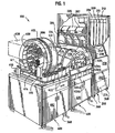
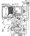
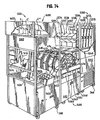
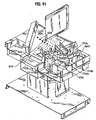
- FIGS. 1 and 3 and 74 and 76 there is illustrated an automated food processing system 100 and an automated food processing system 1100.
- Automated food processing systems 100 and 1100 include a food dispensing device 200, 1200, a fry device 400, 1400 and a food packaging device 600, 1600, respectively.
- Each of dispensing, fry and packaging devices 200, 400 and 600, and 1200, 1400 and 1600, respectively, can be constructed and are sometimes illustrated in “modular" construction or form.
- module construction or form it is meant that dispensing, fry and packaging devices 200, 400 and 600, and 1200, 1400 and 1600, respectively, can exist and be contained in separate cabinets, for example, and also operate independently of the other devices.
- the function of the deactivated or inoperative device can be performed manually. For example, food to be fried could be manually dispensed in place of dispensing device 200 or 1200.
- food to be fried could be fried in a conventional fry vat after being dispensed from dispensing device 200 or 1200 in place of using fry device 400 or 1400 and food that is dispensed and fried in dispensing and fry devices 200 and 400, respectively, could, in turn, be packaged manually, for example.
- each of dispensing, fry and packaging devices 200, 400 and 600, and 1200, 1400 and 1600, respectively can be contained in a separate wheeled cabinet, 202, 402 and 602, and 1202, 1402 and 1602, respectively, as illustrated in FIGS. 1 and 74 .
- dispensing, fry and packaging devices 200, 400 and 600, and 1200, 1400 and 1600, respectively could be mounted as a single unit or in a single cabinet or in "non-modular form," as desired, or more than one of such devices 200, 400 and 600 or 1200, 1400 and 1600, could be so mounted or combined.
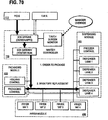
- control system for the dispensing, fry and packaging devices.
- the control system includes a central control system 110 or 1110 that can interface with a point-of-sale system 112 or 1112, respectively.
- the central control system will communicate with separate subcontrol systems 114, 116 and 118 or 1114, 1116 and 1118, respectively, one for each of the dispensing, fry and packaging devices 200, 400 and 600 and 1200, 1400 and 1600, respectively.
- a single central control system could be utilized in place of individual control systems for each of devices 200, 400 and 600 or devices 1200, 1400 and 1600.
- a single central control system could be utilized to control the overall operation of automated food processing system 100 or 1100 as well as controlling the individual functions and aspects of dispensing, fry and packaging devices 200, 400 and 600 or 1200, 1400 and 1600, respectively.
- dispensing devices 200 and 1200, fry devices 400 and 1400 and food packaging devices 600 and 1600 will now be briefly discussed and discussed in detail hereafter.
- dispensing devices 200 and 1200 each function to dispense a quantity of food to be fried to fry device 400 or 1400.
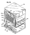
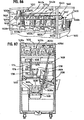
- Dispensing devices 200 and 1200 can include a cabinet 202 or 1202, respectively, to house the components of dispensing device 200 or 1200.
- Cabinet 202 or 1202 will be refrigerated, preferably below 32°F so that the food contents therein will remain frozen. This allows the food stored in dispensing devices 200 or 1200 to remain therein for a long period of time, much longer than if the contents were merely refrigerated (above freezing) or merely at room temperature.
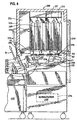
- dispensing devices 200 and 1200 include an uncooked bulk food dispensing container 204 and 1204, respectively.
- Uncooked bulk food dispensing containers 204 and 1204 may be utilized for food such as French fries or chicken nuggets, for example.
- Other types of food may also be contained in a dispenser such as uncooked bulk food dispensing containers 204 and 1204.
- those types of food would be in the form of relatively small pieces compared to relatively large food pieces such as chicken patties, for example.
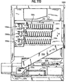
- a large food dispensing container is utilized in the form of magazine food dispensers 206 and 1206.
- Food dispensed from a dispenser of dispensing devices 200 and 1200 is deposited on a conveyor 208 or 1208, respectively, that, in turn, directs the deposited food to a secondary or dump container 210 or bottomless container 1210 for subsequent discharge from dispensing device 200 or 1200, respectively.
- uncooked bulk food dispensing containers 204 and 1204 magazine food dispensers 206 and 1206, conveyors 208 and 1208 and secondary containers 210 and 1210 are contained in cabinet 202 or 1202, respectively, which is a refrigerated environment, preferably maintained below freezing (32°F or lower).
- conveyors 208 and 1208 are each preferably a vibratory conveyor, vibrated by a suitable vibratory mechanism that vibrates conveyor bodies 214 and 1214, respectively.
- Conveyor bodies 214 and 1214 may each take the form of a suitably shaped tray, for example.
- Secondary containers 210 and 1210 can be of a form as desired and includes suitable weighing mechanisms 216 and 1216, respectively, to permit a determination of the quantity of food contained in secondary containers 210 and 1210.
- Weighing mechanisms 216 and 1216 can each be any suitable device to weigh the contents or otherwise determine the amount of food in secondary container 210 or 1210.
- Weighing mechanisms 216 and 1216 may comprise a load cell or a mechanism for determining the volume of food deposited into the respective one of secondary containers 210 and 1210, for example. In this manner, the amount of food that is charged to one of fry devices 400 and 1400 at a particular time can be determined.
- weighing mechanisms 216 and 1216 can be operated during operation of conveyors 208 and 1208, respectively, and the operation of conveyors 208 and 1208 continued until a desired amount of food is deposited in secondary container 210 or 1210. In this manner, a precise amount of food can be delivered to a respective one of secondary containers 210 and 1210, thereby permitting consistency and uniformity in the portion of food that is delivered to fry device 400 or 1400. This is also important to ensure that a sufficient quantity of food is being cooked by automated food processing systems 100 and 1100.
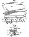
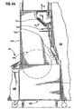
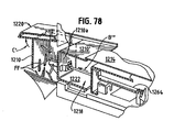
- discharge doors 220 or 1220 of cabinets 202 and 1202 Prior to activation of dumping mechanisms 218 or 1218, discharge doors 220 or 1220 of cabinets 202 and 1202, respectively, are opened by operation of a door opening device which can be any suitable device as desired and in one illustrated embodiment is a cylinder 222 attached to discharge door 220 and movable up and down in the direction of arrow B.
- a respective one of discharge doors 1220 of dispensing device 1200 is opened by lateral movement of the associated one of secondary container 1210, as illustrated in, for example, FIG. 76 .
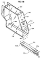
- Cabinets 202 and 1202 are preferably insulated with a suitable insulating material 224 and 1224 that are also provided in discharge doors 220 and 1220. The provision of a suitable insulating material is important, particularly since dispensing devices 200 and 1200 will typically be located proximate or adjacent one of fry devices 400 and 1400 that operate at a substantially elevated temperature thereby typically generating substantial heat.
- dispensing devices 200 and 1200 each includes four dispensing lanes from which food is discharged from dispensing devices 200 and 1200, respectively, and to a suitable location such as one of fry devices 400 and 1400.
- cylinder 222 is activated to close discharge door 220.
- dumping mechanism 218 of secondary container 210 is activated to return secondary container 210 to its upright position to receive more food.
- the associated one of doors 1220 closes by gravity, without the need for a separate closing mechanism.
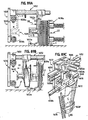
- Each of fry devices 400 and 1400 includes, respectively, a fry wheel 404, a fry vat 406 for containing and heating a suitable cooking oil and a drive mechanism 408 for suitably rotating fry wheel 404. It is to be understood that any suitable frying device can be utilized.
- fry devices 400 and 1400 include a plurality of, in this case four, separate fry wheels 404, 410, 412 and 414, as well as four separate fry vats 416, 406, 420 and 418 and a separate drive mechanism 408 for each fry wheel, each dedicated to a particular one of fry wheels 404, 410, 412 and 414.
- a separate drive mechanism is provided for each of fry wheels 404, 410, 412 and 414 and can be suitably located in cabinet 402 or 1402, preferably in a location that is above the level of cooking oil present in the associated one of fry vats 416, 406, 420 and 418, respectively.
- Fry module 1400 is similar to fry module 400, except that fry module 1400 includes a foam deck and overflow arrangement as hereafter described.
- each of fry wheels 404, 410, 412 and 414 can be as desired to direct food articles loaded therein down and through the fry vat until reaching the other side of the fry vat whereupon the food articles are discharged.
- the rotation can be either continuous or a periodic incremental rotation.
- a suitable drive mechanism can be provided to periodically rotate fry wheel 410 in a desired rotational increment, which may be based on the number of compartments contained in fry wheel 410.
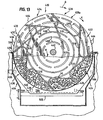
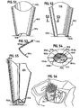
- fry wheel 410 comprises eight food compartments 422, 424, 426, 428, 430, 432, 434, and 436.
- Each of food compartments 422-436 is a perimeter food compartment and open to the perimeter or exterior of fry wheel 410.
- Each of fry wheels 404, 412 and 414 can be similarly configured.
- each of compartments 422-436 is formed from a perforated curved compartment forming member 510.
- a periodic incremental rotation can be based upon 360° divided by the number of compartments.
- each periodic rotation would consist of a rotation of 360° divided by eight compartments or a periodic rotation increment of 45°.
- the food contained, in this case French fries, in compartments 424-430 would remain in cooking oil 454 contained in fry vat 406 for all or part of four incremental rotations, after which the food would be discharged from fry wheel 410 in the next incremental rotation thereof.
- compartment 422 is ready to receive a charge of food to be fried
- compartment 424 has a charge of food that has been just immersed in cooking oil 454.
- Cooking oil 454 is at a level H as illustrated in FIG. 13 , which is dependent upon the amount of food contained in compartments 422-436 that are submerged in cooking oil 454.
- compartment 426 has food contained therein that has gone through two incremental 45° rotations of fry wheel 410
- compartment 428 has food contained therein that has undergone three incremental rotations
- food compartment 430 has food contained therein that has undergone four incremental rotations of fry wheel 410
- compartment 432 which is now empty, has discharged the food contained therein upon the last incremental rotation of fry wheel 410.
- the food contained in food compartment 430 which in this case is a quantity of French fries 455, will be discharged from compartment 430 to the food packaging device which is hereafter briefly described.
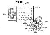
- dispensing member 606 For packaging module or device 600, from inlet chute 604, the food from inlet chute 604 and previously received from fry wheel 410 is deposited into dispensing member 606. Typically, dispensing member 606 will be compartmented into a plurality of compartments that are arrayed along the periphery of rotatable food dispensing member 606.
- Rotatable food dispensing member 606 has a discharge location to discharge the food deposited therein.
- the discharge location is generally located towards an upper portion of rotatable food dispensing member 606.
- a food dispensing chute mechanism 608 is positioned to receive cooked food from the discharge location of rotatable food dispensing member 606.
- food dispensing chute mechanism 608 incorporates a device for weighing or otherwise determining the quantity of food that has been deposited into food dispensing chute mechanism 608. This ensures that when food is dispensed from food dispensing chute mechanism 608 a minimum quantity of food will be dispensed, thereby ensuring that a container 611 or other package that is to receive the food from mechanism 608 will receive a desired charge.
- Food packaging device 600 preferably also includes a suitable automated container handling system 610.
- Automated container handling system 610 is capable of, in a preferred embodiment, selecting container 611 of a desired size, retrieving and grasping container 611, erecting unerected container 611 into an erected form and holding the erected container 611 in position to receive food dispensed from food dispensing chute mechanism 608.
- automated container handling system 610 is capable of moving container 611 having food deposited therein to a container receiving receptacle 612 which receptacle 612 can be transported via a conveyor system 614 to a desired location for subsequent pickup of container 611 having food contained therein by a human operator, for example.
- a food overflow collection member is provided to collect any food dispensed by food dispensing chute mechanism 608 that is not deposited into container 611.
- the overflow food collection device is a rotatable food collection member 613.
- Overflow food collection member 613 functions to collect food dispensed by food dispensing chute mechanism 608 that is not received in container 611 and to recycle food collected by overflow food collection member 613 into food dispensing chute mechanism 608 for subsequent dispensing to a container in a first-in, first-out manner so that overflow food is promptly recycled to dispensing chute 608 for dispensing to a container.
- food packaging device 600 is configured to include a provision by which food contained in dispensing device 600 is routed to waste where it is not desired to dispense such food into a food container.
- a condition could arise, for example, if food is held for too long a period in food packaging device 600.
- This function may be accomplished, for example, by providing a waste discharge location which can be in the form of a waste chute 615 to which food from rotatable food dispensing member 606 and overflow food collection member 613 can be directed.
- chute mechanism 608 is lowered and member 606 is rotated to dispense food to chute mechanism 608, which in turn dispenses into member 613.
- Member 613 is rotated counterclockwise to deliver food to waste chute 615. This process can be continued until all of the food in device 600 is so emptied, if desired.
- a suitable structure for applying a desired quantity of seasoning to food contained in food packaging device 600 is provided.
- a food seasoning device 616 is provided.
- Food seasoning device 616 can be any suitable seasoning device as desired.
- food seasoning device 616 dispenses a desired quantity of seasoning from a bulk storage container through a delivery tube and onto food located in rotatable food dispensing member 606.
- a food seasoning device 616 is provided that directs a desired quantity of seasoning onto food that is contained in a bottom portion of rotatable food dispensing member 606 and inlet chute 604 via a seasoning dispensing head 618.
- conveyor system 614 is composed of a raceway 620 that is an endless loop around the periphery of the top surface of cabinet 602 of food packaging device 600, which in one example can be a modular, wheeled cabinet.
- Conveyor system 614 causes container receiving receptacle 612 to travel around raceway 620 to a food container pickup location 622 where a human operator can pickup food containers having food therein.
- conveyor system 614 includes structure for stopping movement of a container/receiving receptacle 612 at a predetermined location when carrying a food container, such as at food container pickup location 622.
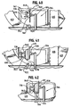
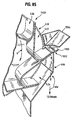
- Such structure in one embodiment may comprise a gate structure 928 or 928' of FIG. 45 and FIGS.
- gate structure 928 or 928' will be located at a height that is above the top of the receptacle when located on conveyor system 614 so that movement of container/receiving receptacle 612 is prevented or stopped only for a receptacle 612 that has a food container 611 disposed thereon.
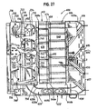
- the pickup location can be configured as desired and slightly different configurations 622 and 622' are shown in FIG. 45 and FIGS. 25-27 , respectively.
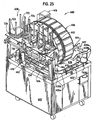
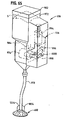
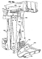
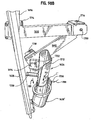
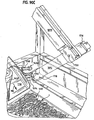
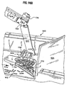
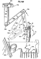
- the basic elements of food packaging device 1600 may include an inlet chute 1604, preferably a salting device 1606, preferably gates 1608 and 1610 operatively associated with inlet chute 1604, a holding bin 1612 for French fries, an automated French fry container filling device 1614 that includes an automated mechanical arm 1616 and a carriage 1618, a filled French fry container drop-off location and holding structure 1620 and preferably, a container handling system 1622 typically for carton storage, carton erection and handling, suitable for use with French fry container filling device 1614, as hereafter described in further detail. As shown in FIG.
- an inlet chute 1603 is provided to feed cooked food products into holding bin 1603' received from fry wheel 404, typically for food items such as chicken filets, fish filets or chicken nuggets, for example, received from lane 1240.
- Bin 1602' may be heated, if desired.
- packaging device or module 1600 is as follows.
- Food from fry module 400 or 1400, such as from fry wheel 410 is deposited onto the inlet portion of inlet chute 1604.
- gate 1608 will be positioned to prevent the passage of French fries past gate 1608.
- Salting device 1606 then operates to apply a desired quantity of salt or other seasoning to the bulk amount of French fries on inlet chute 1604 contained upstream of gate 1608.
- Salting device 1606 can be laterally moved along a carriage 1606' during dispersing of the salt or other seasoning to help ensure seasoning coverage over the entire quantity of French fries in inlet chute 1604 that are upstream of gate 1608.
- one or more salter devices 1606 can be mounted in a desirable stationary position above inlet chute 1604 or some other desirable location without a carriage. Salter device 1606 is similar to food seasoning device 616 described in detail hereafter.
- Gate 1608 preferably is composed of reciprocable fingers that can be raised and lowered relatively rapidly so that as the bulk amount of French fries travel past gate 1608, the fingers provide a declumping action on the French fries.
- Gate 1610 can be in a position to retain the French fries at a lower portion of inlet chute 1604, such as if additional French fries are not needed in holding bin 1612. When gate 1610 is in an open or lowered position, French fries in the low portion of chute 1604 are free to travel into holding bin 1612.
- a vibratory mechanism 1624 as shown in FIG. 76 may also be associated with inlet chute 1604 so that inlet chute 1604 vibrates to facilitate the passage of fries along inlet chute 1604 and into holding bin 1612.
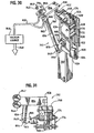
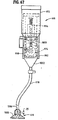
- French fry container filling device 1614 operates to fill erected French fry containers that typically will be individual portion-sized French fry containers, and is composed of a multilink mechanical arm 1616.
- Mechanical arm 1616 has an end-of-arm tool 1626 that is capable of grasping a French fry container, scooping it into French fries contained in holding bin 1612 to fill the French fry container with French fries, relatively gently shaking the filled French fry container to seat the French fries in the container and to dislodge any loosely contained French fries and depositing the filled French fry container at a drop-off location.
- the filled French fry container is shaken over the holding bin so that French fries that are shaken from the container fall into holding bin 1612 and so that French fries become more firmly seated in the French fry container.
- automated mechanical arm 1616 can be configured and operated to mimic the arm, wrist and hand action of a human operator in scooping French fries into a French fry container to fill the container and shaking the filled French fry container to remove loosely contained French fries and to more firmly seat French fries contained in the container.
- Food packaging device 1600 preferably also includes a suitable container handling system 1622.
- Container handling system 1622 is capable of, in a preferred embodiment, selecting a container 611 of a desired size, retrieving and grasping container 611, erecting unerected container 611 into an erected form and delivering erected container 611 to French fry container filling device 1614.
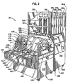
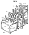
- FIGS. 2 and 75 there are illustrated various alternate examples of automated food processing systems 101 and 1101.
- Automated food processing systems 101 and 1101 include, respectively, a food dispensing device 201, 1201 which is similar to food dispensing devices 200 and 1200, previously briefly described, where like reference numerals represent like elements.
- Food dispensing devices 201 and 1201 include fewer uncooked bulk food dispensing containers 204, 1204 and additional magazine food dispensers that are similar to magazine food dispensers 206 and 1206, previously referred to. Otherwise, dispensing devices 201 and 1201 are similar to dispensing devices 200 and 1200, previously described, respectively.
- Automated food processing systems 101 and 1101 also include fry devices 400 and 1400, respectively, which have been described.
- automated food processing systems 100 and 1100 and automated food processing systems 101 and 1101 do not include an automated packaging device such as automated packaging devices 600 or 1600.
- a food storage device 635 is provided, which may be contained on a movable cart 635'.
- Food storage device 635 allows food cooked by food frying devices 400 or 1400 to be stored in a heated environment for subsequent manual processing.
- food storage device 635 includes separate heated product receiving receptacles 637, 639, 641 and 643.
- Each receptacle 637, 639, 641 and 643 is dedicated to receiving food from a respective one of fry wheels 410, 412, 414 and 404, respectively.
- each receptacle 637-643 can have placed therein a suitable container to receive food, such as handled trays 645, 647, 649 and 651.
- a food item F is being discharged from fry wheel 414 down a chute 653 and into handled tray 649 contained within heated receptacle 641. Food item F can be stored therein for a period of time until it is ready for subsequent processing.
- FIGS. 74-91 there are illustrated an alternate dispensing device or module 1200, fry device or module 1400 and packaging device or module 1600.
- FIGS. 1-10 and 74-84 there are illustrated various food dispensing devices and portions thereof.
- Food dispensing devices 200 and 1200 are illustrated or partially illustrated in each of FIGS. 1 and 3-8 and 74 and 76-84.
- Food dispensing device 200 includes a cabinet 202, bulk uncooked food dispensing containers 204, 205 and 207, magazine food dispensers 206, 209, 211 and 213, and a suitable conveyor system for each lane 234, 236, 238 and 240 of food dispensing device 200.
- food dispensing device 1200 includes a cabinet 1202, bulk uncooked food dispensing containers 1204, 1205 and 1207, magazine food dispenser 1206, 1209, 1211, 1213 and 1215, and a suitable conveyor system for each lane 1234, 1236, 1238 and 1240 of food dispensing device 1200.
- any suitable number of magazine dispensers can be used for a particular lane, such as one, two, three, four, five or more, and the illustrated five is merely an example.
- lanes 234, 1234 receive material from bulk hoppers 204, 1204, lanes 236, 1236 receive food material from bulk hoppers 205, 1205, lanes 238, 1238 receive food material from bulk hoppers 207, 1207 and lanes 240, 1240 receive dispensed food from magazine food dispensers 206, 209, 211 and 213, and 1206, 1209, 1211, 1213 and 1215, respectively, as will be described hereinafter in greater detail, particularly with respect to food dispensing device 201 of FIG. 2 , for example.
- Food dispensing device 1200 is similar to food dispensing device 200, except that device 1200 has a different secondary container, exterior doors and differences in the conveyor apparatus, as hereafter described.
- Each lane 234, 236, 238 and 240 or 1234, 1236, 1238 and 1240 dispenses food that is subsequently directed to fry wheels 410, 412, 414 and 404, respectively.
- Lane 238 includes uncooked bulk food dispensing container 207 and a food handling system 242 which in this embodiment is identical for each lane 234, 236, 238 and 240 as well as for each lane of food dispensing device 201. It should be noted that food handling system 242, as for example, illustrated in FIGS. 3-6 is depicted with respect to lane 240 and that food handling system 242 is the same for each lane 234, 236, 238 and 240.
- Food handling system 242 includes conveyor system 208, secondary container 210, weighing mechanism 216 and dumping mechanism 218.
- Conveyor system 208 includes vibratory mechanism 212 and conveyor body 214.
- Uncooked bulk food dispensing container 204 can be of a shape and dimension generally as desired.
- uncooked bulk food dispensing container 204 has an upper opening to permit a supply of food to be placed in uncooked bulk food dispensing container 204.
- Upper opening 244 as illustrated is located in an upper rear portion of uncooked bulk food dispensing container 204 and can be conveniently accessed via a rear door 246 of cabinet 202.
- Rear door 246 preferably is insulated with suitable insulation material 224.
- Uncooked bulk food dispensing container 204 is composed of a pair of opposed upper sidewalls 248, a pair of generally opposed lower sidewalls 250 and front and rear walls 252 and 254, respectively, which connect together upper sidewalls 248 and lower sidewalls 250 to provide uncooked bulk food dispensing container 204.
- Front wall 252 includes a lower portion 252' that extends inwardly from top to bottom to further facilitate discharge of food contained in uncooked bulk food dispensing container 204.
- lower generally opposed sidewalls 250 are slightly indented from top to bottom to facilitate the discharge of food that may be contained therein.
- Uncooked bulk food dispensing container 204 includes a bottom opening 256 that permits the discharge of food contained therein.
- Bottom opening 256 can be configured as desired and in the illustrated embodiment the entire bottom of uncooked bulk food dispensing container 204 is open.
- uncooked bulk food dispensing container 204 is particularly suited for use with food such as French fries and chicken nuggets as well as other types of food of relatively small size.
- Uncooked bulk food dispensing container 204 is suitably mounted within cabinet 202. While a suitable mounting structure can be utilized, it is preferred to utilize a structure that will minimize heat transfer from the exterior and through cabinet 202 to uncooked bulk food dispensing container 204, particularly where cabinet 202 is refrigerated, especially where temperatures below freezing are utilized.
- front mounting bracket 258 and rear mounting bracket 260 each are configured to minimize heat transfer from cabinet 202 to uncooked bulk food dispensing container 204.
- front mounting bracket 258 and rear mounting bracket 260 include openings, 258' and 260', respectively, to minimize such heat transfer and to maximize airflow around the containers 204, 205, 207 and dispensers 206, 209, 211 and 213.
- brackets 258 and 260 materials of low thermal conductivity can also be utilized, if desired, for brackets 258 and 260.
- materials of low thermal conductivity can also be utilized, if desired, for brackets 258 and 260.
- the surface area contact and cross-sectional area of mounting brackets 258 and 260 should be minimized to reduce heat transfer and "hot spots" on uncooked bulk food dispensing container 204.
- conveyor body 214 which in the illustrated example is a suitably dimensioned pan.
- Conveyor body 214 is suitably mounted to vibratory mechanism 212 to effect vibration of conveyor body 214 as well as food contained therein and food contained in uncooked bulk food dispensing container 204, and in particular the lower portion of container 204. This vibration facilitates the discharge of food from uncooked bulk food dispensing container 204 and causes food contained in conveyor body 214 to travel in the direction of arrow G.
- Any suitable conveyor system can be used in accordance with one aspect of the invention.
- Vibratory mechanism 212 is preferably an electromagnetic vibrating mechanism. Vibratory mechanism 212 in one example produces a vibrating stroke at the surface of conveyor body 214. The stroke results from the action of an electromagnet that pulls conveyor body 214 sharply down and backward and then allows it to spring up and forward. Typical vibratory mechanisms of this type run at about 3,600 vibrations/minute at 60Hz power. The power of the vibrating stroke can be controlled by a suitable drive module as is known in the art. In one example, vibratory mechanism 212 can be operated at about 85% of full power during filling of secondary container 210 with food.
- vibratory mechanism 212 can be run continuously, then pulsed by turning its power on and off periodically so that vibratory mechanism 212 operates about 50% of the time to finish filling secondary container 210 with a desired quantity of food, thereby providing better control on the last part of the food charged to secondary container 210.
- Food dispensing device 200 preferably includes a suitable mechanism to determine the weight or volume of a charge of food delivered by conveyor 208 to secondary container 210. The amount may be determined either by weightor volume, for example.
- weighing mechanism 216 is operatively interfaced with secondary container 210 to provide an indication of the weight of food contained in secondary container 210.
- the weight sensed in secondary container 210 by weighing mechanism 216 is communicated with subcontrol system 114 of food dispensing device 200.
- Subcontrol system 114 monitors and controls the operative functions of food dispensing device 200 as hereinafter described in greater detail.
- a level sensor can be employed in uncooked bulk food dispensing container 204 to provide an indication of the amount of food stored therein that is available for dispensing.
- Any suitable level indicator known in the art can be utilized in accordance with the invention such as photoelectric, weight, turning fork and others, for example.
- Secondary container 210 can be considered as a dump container and has associated therewith, dumping mechanism 218 for rotating secondary container 210 through an arc as indicated by arrow B sufficiently to dump the contents of secondary container 210.
- Any suitable dumping mechanism can be utilized.
- Illustrated dumping mechanism 218 includes a dump cylinder 264 that is secured to a base 266.
- Dump cylinder 264 can selectively rotate a drive gear or wheel 268 that, in turn, is operatively associated with a follower gear or wheel 270 to cause rotation of follower gear or wheel 270.
- Secondary container 210 is rigidly secured to follower gear or wheel 270 so that when follower gear or wheel 270 is rotated by drive gear or wheel 268 secondary container 210 is rotated through an arc that causes secondary container 210 to rotate forward to a dumping position as illustrated in phantom lines in FIG. 3 indicated by reference numeral 210'. Such movement is caused by extension of dump cylinder 264. Similarly, retraction of dump cylinder 264 moves secondary container 210 from the dump position indicated by reference numeral 210' to the upright position indicated by reference numeral 210 in FIG. 3 where secondary container 210 is ready to receive a charge of food from conveyor 208, which as illustrated is French fries FF.
- Secondary container 210 is composed of a pair of opposed spaced apart sidewalls 211' (only one sidewall 211' is illustrated and is depicted in a half-moon configuration) and a pair of sidewalls 213a and 213b, oriented in a V-shaped relationship when container 210" is configured to receive food from conveyor body 214.
- Sidewall 213a is mounted for pivotal movement about apex 215 of sidewalls 213a and 213b.
- Such movement is accomplished by a drive mechanism similar to cylinder 264, drive gear 268 and driven gear 270, which in this embodiment are cylinder 264', drive gear 268' and driven gear 270', which gear 270' is attached to sidewall 213a.
- a drive mechanism similar to cylinder 264, drive gear 268 and driven gear 270, which in this embodiment are cylinder 264', drive gear 268' and driven gear 270', which gear 270' is attached to sidewall 213a.
- cylinder 264' When cylinder 264' is extended, sidewall 213a is caused to pivot downwardly as indicated by arrow AA to the position of sidewall 213a shown in phantom, thereby causing the contents (French fries FF) of container 210" to be dumped.
- Sidewalls 211' act as sidewall guides for sidewalls 213a and 213b when sidewall 213a is in a lowered position, in which case sidewalls 213a and 213b act as a chute or
- Lane 1234 includes uncooked bulk food dispensing container 1204 and a food handling system 1242 which in this embodiment is identical for each lane 1234, 1236, 1238 and 1240 as well as for each lane of food dispensing device 1201. It should be noted that food handling system 1242 and components thereof, as for example, illustrated in FIGS. 76-84 is depicted with respect to lane 1234 and that food handling system 1242 is generally the same for each lane 1234, 1236, 1238 and 1240 unless otherwise noted.
- Food handling system 1242 includes conveyor 1208, secondary container 1210, weighing mechanism 1216 and dumping mechanism 1218.
- Conveyor system 1208 includes vibratory mechanism 1212 and conveyor body 1214.
- Uncooked bulk food dispensing container 1204 can be of a shape and dimension generally as desired and can be similar to container 204 previously described.
- uncooked bulk food dispensing container 1204 has an upper opening to permit a supply of food to be placed in uncooked bulk food dispensing container 1204.
- Upper opening 1244 as illustrated is located in an upper rear portion of uncooked bulk food dispensing container 1204 and can be conveniently accessed via a rear door 1246 of cabinet 1202.
- Rear door 1246 preferably is insulated with suitable insulation material 1224.
- Uncooked bulk food dispensing container 1204 is similar to container 204 previously described.
- Uncooked bulk food dispensing container 1204 includes a bottom opening 1256 that permits the discharge of food contained therein.
- Bottom opening 1256 can be configured as desired and in the illustrated embodiment the entire bottom of uncooked bulk food dispensing container 1204 above conveyor body 1214 is open.
- uncooked bulk food dispensing container 1204 is particularly suited for use with food such as French fries and chicken nuggets as well as other types of food of relatively small size.
- Uncooked bulk food dispensing container 1204 is suitably mounted within cabinet 1202, such as described with respect to food dispensing container 204.
- secondary container 1210 which is positioned to receive food items from conveyor body 1214 of conveyor 1208.
- Conveyor body 1214 is suitably mounted to vibratory mechanism 1212 to effect vibration of conveyor body 1214 as well as food contained therein and food contained in uncooked bulk food dispensing container 1204, and in particular the lower portion of container 1204. This vibration facilitates the discharge of food from uncooked bulk food dispensing container 1204 and causes food contained in conveyor body 1214 to travel in the direction of arrow G'.
- Any suitable conveyor system can be used in accordance with one aspect of the invention.
- the same type of vibratory mechanism can be used as previously described with respect to vibratory mechanism 212.
- a regulating device which may be an elongated rotatable device, may be provided at a lower portion of bulk food dispensing container 207 or 1204, or otherwise located between the bottom or a bottom portion of container 207 or 1204 and above or along an upper portion of conveyor 214 or 1214.
- the regulating device limits the quantity of French fries or other food that is delivered to conveyor 214 or 1214 so that conveyor 214 or 1214 does not get overloaded or jammed with food items.
- Such a device is illustrated in FIGS. 77A and 77B and includes an elongated vane device 1257, rotatable by a suitable motor device (not shown).
- vane device 1257 can be rotated about 120° in either direction and after rotating, food (e.g., French fries) is caused to be dispensed into conveyor 214 or 1214.
- food e.g., French fries
- vane device 1257 is rotated 120° in the motor drive in the opposite direction. The 120° rotation typically is accomplished in about 2 seconds, for example.
- vane device 1257 is composed of three equally spaced apart vanes or paddles 1257a-c, mounted to a central triangular section 1259. Vane device 1257 can be conveniently removed from bulk food dispensing container 1204', through hinged access door 1261, as illustrated in FIGS. 77A and 77B , which can be opened and closed by rotation in the direction of arrows OP and CL, respectively.
- a support 1265 for one end of vane device 1257 is provided on an interior portion of door 1261 as shown in FIG. 77B .
- a suitable aperture 1263 is provided through container 1204' for the motor device for vane device 1257, as shown in FIG. 77B with vane device 1257 removes.
- Container 1204' can be otherwise similar to container 1204 and can be constructed of, for example, transparent walls 1267, 1269, 1271 and 1273 as illustrated in FIGS. 77A and 77B , with front wall 1275 being metal or another suitable material.
- Food dispensing device 1200 preferably includes a suitable mechanism to determine the weight or volume of a charge of food delivered by conveyor 1208 to secondary container 1210. The amount may be determined either by weight or volume, for example.
- weighing mechanism 1216 is operatively interfaced with secondary container 1210 to provide an indication of the weight of food contained in secondary container 1210.
- the weight sensed in secondary container 1210 by weighing mechanism 1216 is communicated with subcontrol system 1114 of food dispensing device 1200.
- Subcontrol system 1114 is similar to subcontrol system 114 and monitors and controls the operative functions of food dispensing device 1200 as hereinafter described in greater detail.
- a level sensor can be employed in uncooked bulk food dispensing container 1204 to provide an indication of the amount of food stored therein that is available for dispensing.
- Any suitable level indicator known in the art can be utilized in accordance with the invention such as photoelectric, weight, turning fork and others, for example.
- Secondary container 1210 is a bottomless box-like container having an open top and is composed of generally upstanding sidewalls.
- a floor or platform 1222 is stationary and is located beneath container 1210 when in the retracted or home position as shown in FIG. 77 . In this position, container 1210 is able to receive food items from associated conveyor 1208.
- An elongated lip or tray 1210' extends from back wall 1210a of container 1210 so that when container 1210 is in the dump position, lip or tray 1210' is located below the discharge end of conveyor body 1214 so that any articles of food that may fall from the end of conveyor body 1214 will be collected on lip or tray 1210' and those items will be deposited into container 1210 as it is retracted to the home or filling position.
- a suitably removable catch pan (not shown) is located between the bottom of conveyor 1214 or 1214' and the top of lip 1210' so that food particles or ice crystals falling through holes in the bottom of conveyor 1214 or 1214' do not land on lip 1210'.
- Secondary container 1210 can be considered as a dump container and has associated therewith dumping mechanism 1218 for laterally moving secondary container 1210 to retracted and extended positions relative to stationary floor or platform 1222 as indicated by arrows B', B" and B"' in FIGS. 76-78 , respectively, sufficiently to open door 1220 and to dump the contents of secondary container 1210.
- Any suitable mechanism can be utilized to effect the desired lateral movement of container 1210 and as illustrated, dumping mechanism 1218 includes a dump cylinder or actuator 1264 that is secured to a base 1266.
- Dump cylinder 1264 can selectively laterally translate secondary container 1210 which is secured to dump cylinder 1264 so that when secondary container 1210 is laterally moved or translated to the left, as illustrated in FIG.
- secondary container 1210 moves forward to a dumping position. Such movement is caused by extension of dump cylinder 1264. Similarly, retraction of dump cylinder 1264 laterally moves secondary container 1210 from the dump position to the home or filling position as shown in FIG. 77 where secondary container 1210 is ready to receive a charge of food from conveyor 1208, which in the illustrated embodiment the food is French fries FF.
- Conveyor body 1214' is particularly suitable for conveying chicken nuggets and similarly shaped types of food items.
- Conveyor body 1214' has a tray-like body 1214a and a discharge end 1214b and an inlet portion 1214c.
- Inlet portion 1214c includes an upwardly extending dividing member 1214d that divides conveyor body 1214' into two food inlet passageways 1214e and 1214f. As illustrated, dividing member 1214d is saddle-shaped.
- Inlet passageways 1214e and 1214f merge into a single passageway 1214g which initially is relatively wide at portion 1214g' and subsequently narrows as passageway 1214g progresses towards discharge end 1214b.
- Such arrangement promotes declumping of the chicken nuggets contained in bulk container 204 or 1204 and permits the chicken nuggets to be conveyed in a single file orientation towards discharge end 1214b.
- This permits effective dispensing and metering of chicken nuggets into either secondary container 210 or 1210.
- the width of passageway 1214g after narrowing is about the width of a single chicken nugget and may slightly increase if desired towards discharge end 1214b if desired.
- passageway 1214g has a non-linear path and may be serpentine or zigzag as illustrated, which further promotes accurate dispensing of chicken nuggets or other similarly shaped food articles, which could include, as non-limiting examples, breaded shrimp, cheese nuggets and jalapeno poppers.
- Passageway 1214g may include a plurality of holes 1214h or perforations through bottom 1214i of conveyor body 1214' to permit small unwanted ice crystals or food particles to pass therethrough so that such items are not dispensed to fry module 400 or 1400.
- FIGS. 81 and 82 there is illustrated an example of a dispensing door arrangement.
- one door 1220, 1220a, 1220b and 1220c is provided for each respective product dispensing lane 1238, 1234, 1236 and 1240, respectively.
- Each of doors 1220, 1220a, 1220b and 1220c are hinged at the top to close by gravity and are opened when container 1210 associated with a particular one of doors 1220, 1220a, 1220b and 1220c is laterally translated by cylinder 1264 to a dumping position as shown in FIG. 78 with respect to door 1220 which has been opened in the direction of arrow C'.
- Door edge overlapping members 1221a, 1221 b and 1221c are hinged to swing open in a manner similar to doors 1220, 1220a, 1220b and 1220c.
- Door edge overlapping members 1221a, 1221b and 1221c are each associated with the respective adjacent doors 1220, 1220a, 1220b and 1220c as illustrated in FIGS. 81 and 82 and are hinged for movement similar to that independent of doors 1220, 1220a, 1220b and 1220c, such as in the direction of arrow XX in FIG. 82 .
- the door edge overlapping members provide a more complete seal between the sides of doors 1220, 1220a, 1220b and 1220c that are not adjacent the ends of dispensing device 1200, thereby restricting entry of water vapor to the interior of dispensing device 1200 when doors 1220, 1220a, 1220b and 1220c are in a closed position.
- the adjacent door edge overlapping members 1221a, 1221b and 1221 c also open as shown in FIG. 81 , where the opening of door 1220 causes door edge overlapping members 1221 b and 1221 c to open, which can be moved independently of doors 1220, 1220a, 1220b or 1220c as shown in FIG. 82 .
- FIGS. 83 and 84 there are illustrated various examples of a declumping member.
- FIG. 83 which is a partial fragmentary exploded view of dispensing device 1200 showing generally vertically extending declumping member 1370 comprises a downwardly depending pin that is attached to a lower portion of bulk dispensing container 1204 or to some other suitable structure.
- Member 1370 is stationary and extends downwardly to a position just above the bottom of conveyor body 1214.
- member 1370 is stationary and tends to declump or break apart a frozen clump or mass of French fries as they vibrate and travel past member 1370.
- FIG. 84 is a partial fragmentary exploded view of dispensing device 1200 showing an alternate embodiment declumping member 1372 that is attached to the bottom of conveyor body 1214 and extends upwardly therefrom. French fries or other food items conveyed along conveyor body 1214 will encounter member 1372 which will tend to declump or break apart a clump or mass of French fries as they travel past member 1372.
- declumping members may be used in place of members 1370 and 1372. Any structure that tends to declump or break apart a mass or frozen clump of French fries or similar food can be used.
- Subcontrol system 114 coordinates the operation of the various functions of food dispensing device 200 and/or food dispensing device 1200. For example, when food dispensing device 200 or 1200 is ready to dump a charge of food from secondary container 210 or 1210 out of food dispensing device 200 or 1200, subcontrol system 114 activates cylinder 222 (only for device 200) to open discharge door 220 thereby permitting the food charge in secondary container 210 to be dumped by dumping mechanism 218 through open discharge door 220. Dump cylinder 264 or 1264 is extended causing secondary container 1210 of device 1200 to open door 1220 and dump the contents therein to fry device 1400.
- subcontrol system 114 causes dump cylinder 264 or 1264 to be retracted thereby returning secondary container 210 or 1210 to a position ready to accept a further charge of food from conveyor system 208 or 1208.
- cylinder 222 has one end rigidly secured to cabinet 202 or some other suitable location and the other end of cylinder 222 is attached to discharge door 220.
- discharge door 220 will have a suitable guide mechanism, which may be tracks, slots or other suitable apparatus to guide discharge door 220 to its open and closed positions.
- Cylinder 222 is operable to move door 220 up and down as indicated by arrow B in FIG. 6 to thereby open and close discharge door 220 as desired.
- discharge door 220 extends across all four dispensing lanes 226, 228, 230 and 232. If desired, a separate discharge door could be provided for each of dispensing lanes 226, 228, 230 and 232 such as doors 1220, 1220a, 1220b and 1220c previously described.
- subcontrol system 114 causes activation of cylinder 222, when present, to close discharge door 220 to prevent heat from entering into cavity 272 of food dispensing device 200 in which the food and various dispensing mechanisms are contained as illustrated in FIGS. 3 and 6 , for example.
- Food dispensing devices 200 and 1200 can contain suitable refrigeration components 274 such as within a lower portion of cabinet 202 as shown schematically in FIG. 1 .
- refrigeration components 274 provide sufficient cooling to provide a below freezing temperature environment in cavity 272.
- suitable refrigeration components can be provided exteriorly of cabinet 202 and even at a remote location as desired.
- a storage compartment 276 and a storage compartment door 278 may also be provided in cabinet 202.
- An upper side access door may also be provided to permit operator access to the interior of cavity 272 where uncooked bulk food dispensing containers 204 and/or magazine food dispensers 206 and/or 209, 211 and 213 are located.
- FIGS. 2 and 7-10 there is illustrated an embodiment of a food dispensing device 201 in accordance with the present invention.
- Food dispensing device 201 has many similarities to food dispensing device 200 previously described where like reference numerals represent like elements.
- food dispensing device 201 includes cabinet 202, four product dispensing lanes 226, 228, 230 and 232 with each such lane incorporating conveyor 208, secondary container 210, vibratory mechanism 212, conveyor body 214, weighing mechanism 216, dumping mechanism 218, discharge door 220, cylinder 222, insulating material 224, food handling system 242, upper opening 244, rear door 246, uncooked bulk food dispensing container 204 which is associated with product dispensing lane 234, a dump cylinder 264 for each product dispensing lane, cavity 272, refrigeration components 274, storage compartment 276 and a storage compartment door 278.
- Product dispensing lanes 228, 230 and 232 each have associated therewith a plurality of magazine food dispensers 280-308 arrayed to provide in the embodiment illustrated in FIG. 9 five magazine food dispensers per product dispensing lane in which there are three product dispensing lanes serviced by the foregoing magazine food dispensers. Consequently, magazine food dispensers are configured in a three-by-five array and are suspended from a magazine food dispenser support 310 as shown in FIG. 9 . Each row of three magazine food dispensers depends from magazine food dispenser support 310 via a slide assembly 312. Slide assembly 312 is similar to a drawer slide including a pair of first and second elongated telescoping left and right slides 314 and 316, respectively. Suitable upper rollers 318 are mounted to magazine food dispenser support 310 and lower rollers 320 depend from magazine food dispensers 280-308 for traversing left and right elongated telescoping slides 314 and 316.
- Suitable mounting brackets 322 are provided which depend upwardly from magazine food dispenser support 310 for mounting to cabinet 202.
- suitable mounting brackets 324 are provided which depend downwardly from magazine food dispenser support 310 for mounting slide assembly 312 thereto allowing magazine food dispensers 280-308 to depend therefrom.
- Magazine food dispenser support 310 has a series of holes 326 and 328 therein. Holes 326 can be provided to allow increased airflow and cooling. Holes 328 can also be provided to provide increased airflow and cooling for magazine food dispensers 280-308.
- Magazine food dispensers 280-308 and 206, 209, 211 and 213 briefly discussed with respect to food dispensing device 200 are similar in construction. Magazine food dispenser 206 will be discussed with respect to FIGS. 7 and 8 and it is to be understood that the other magazine food dispensers are of similar construction.
- Magazine food dispenser 206 includes a body or housing 330 that includes sidewalls 332 and 334, front walls 336 and 338 and corresponding rear walls (not shown) and can be attached in a removable manner if desired, including in a snap-on arrangement to facilitate cleaning. Magazine food dispenser 206 also includes a top member or cover 340 having mounted thereover a drive mechanism 342.
- Drive mechanism 342 includes a drive gear or wheel 344 and a driven wheel or gear 346. Depending from each of drive wheel or gear 344 and driven wheel or gear 346 is a spiral flight that is vertically or generally vertically oriented relative to the longitudinal axis of spiral flights 348 and 350.
- Body 330 of magazine food dispenser 206 can include substantial open portions such as front open portion 352 and a corresponding rear open portion (not shown). Such open portions may have a cover or access door thereover (not shown). Such open portions can be desirable to permit airflow through magazine food dispenser 206 since generally such dispenser will be contained in a refrigerated environment and such openings help ensure that food contained therein remains frozen or chilled as desired.
- a vertical divider (not shown) can be provided between spiral flights 348 and 350 if desired.
- a plurality of generally vertically disposed and spaced apart rods 354, 356 and 358 may be provided at the front of magazine food dispenser 206 adjacent spiral flights 348 and 350 and similar rods can be provided at the back of magazine food dispenser 206.
- Rods 354, 356 and 358 prevent food pieces from falling out of spiral flights 348 and 350 and to maintain spiral flights 348 and 350 in a vertical orientation.
- Magazine food dispenser 206 has an open bottom 360 through which food pieces can be dispensed during operation.
- drive wheel 344 can be driven by a suitable electric motor, such as an electric motor 362, 364 and 366 shown with respect to magazine food dispensers 280, 282 and 284 in FIG. 9 .
- a suitable electric motor such as an electric motor 362, 364 and 366 shown with respect to magazine food dispensers 280, 282 and 284 in FIG. 9 .
- other drive devices could be used, including, for example, a rotary air or hydraulic cylinder.
- Rotation of drive wheel 344 in a clockwise direction causes driven wheel 346 to rotate in a counterclockwise direction by virtue of the intermeshing or contact between drive wheel or gear 344 and driven wheel or gear 346.
- Such rotation causes corresponding rotation of spiral flights 348 and 350, respectively.
- Food contained by spiral flights 348 and/or 350 is moved downwardly by virtue of such rotation.
- Such food When such food reaches the bottom of spiral flights 348 and/or 350, respectively, such food is discharged from magazine food dispenser 206 through open bottom 360 and onto conveyor 208 for handling as previously described or onto conveyor 1208, for example.
- a single motor could be used to drive a plurality of dispensers 280, 282 and 284, etc. through a suitable drive mechanism (not shown).
- pieces of food can be contained by magazine food dispenser 206 in two different ways.
- individual pieces of food may each be contained by a single elongated spiral flight 348 or 350 as shown with respect to food pieces F1 and F2, respectively.
- Food pieces F1 and F2 can be any type of desired food and may be a food item such as a hash brown, an individual portion pie, rectangular food patty, or other type of food as desired.
- Chicken nuggets and other food can also be dispensed with the bulk dispenser previously described. Larger items of food can span across portions of both elongated spiral flights 348 and 350 as illustrated with respect to food item F3, which may be a larger food item, such as a chicken patty, or other type of food article as desired.
- Spiral flights 348 and 350 can be of a desired radial diameter so that the food piece or pieces that are to be contained and dispensed in magazine food dispenser 206 can be accommodated as illustrated in FIG. 8 .
- Each spiral can contain a food piece so that as illustrated in FIG. 7 , the illustrated spirals of spiral flights 348 and 350 could each accommodate twelve food pieces such as food pieces F1 or F2 for a total of twenty-four food pieces or twelve food pieces such as food piece F3 of FIG. 8 .
- spiral flights having a greater or lesser number of flights can be used if desired to hold a greater or lesser number of food pieces, respectively.
- a suitable home position sensor 362' can be utilized to indicate a home or start position of each of spiral flights 348 and 350. As illustrated in FIG. 7 , a pair of position indicating sensors 362' and 364' are utilized and mounted on drive wheel 344 180° apart for more precise locating of the position of spiral flights 348 and 350. Sensors 362' and 364' can be proximity sensors that align with corresponding sensor pickups on the respective drive gear or motor for magazine food dispenser 206 (not shown).
- spiral flights 348 and 350 are offset by one rotation so that a single food item such as food item F1 or F2 in FIG. 8 will be dispensed from one of either spiral flight 348 or 350 for each one-half rotation of spiral flights 348 and 350.
- Food dispensing devices 1200 ant 1201 may incorporate magazine dispensers as previously described.
- dispensing device 1200 has a one-by-five array of magazine dispensers, such as magazine dispenser 206 and dispensing device 1201 incorporates magazine dispensers 280-308 as previously described for dispensing device 201.
- Food dispensing devices 1200 and 1201 utilize the conveyor system and food dump mechanism as previously described with respect to dispensing device 1200.
- food dispensing devices 200 and 1200 and food dispensing devices 201 and 1201 are constructed in modular form, an example of which is illustrated in FIGS. 1 and 74 and 2 and 75 , respectively.
- Wheels 368 can be provided to permit cabinets 202, 402 and 602 to be suitably transported across a relatively flat surface, such as a restaurant work area floor.
- a magazine dispenser such as magazine food dispenser 1206 can be oriented horizontally instead of vertically.
- Such a horizontally oriented magazine dispenser can be configured to discharge food items onto an inclined chute contained within the freezer compartment or cavity of dispenser 200 or 1200 (for example cavity 272 of device 200) to receive dispensed food items, which chute is positioned with a discharge end oriented to deposit the food items directly into secondary container 210 of dispensing device 200 or secondary container 1210 of dispensing device 1200.
- the vibrating conveyor need not be used.
- the chute may be constructed in any suitable configuration, such as, for example, as non-limiting examples, chute 498,1603 or 1554, as illustrated in FIGS. 12 , 74 and 85 , respectively.
- a single spiral flight such as spiral flight 348, may be used in the horizontal orientation instead of two spiral flights.
- FIGS. 77C and 77D illustrate a magazine dispensing device 1300 for the dispensing of individual food items, which is orientated horizontally, forming part of food dispensing module 1302.
- Food items are conveyed by a single spiral conveyor 1304 for each spiral magazine 1306a-c in the direction of arrow SS.
- Each spiral magazine 1306a-c is driven by a suitable motor 1308 or other Suitable drive mechanism.
- the food item then travels down chute 1310 in the direction of arrow UU and into secondary container 1312, which is similar to secondary container 1210, except rear wall 1314 is slightly inclined.
- a suitable sensor may be utilized to sense or count the number of food articles being dispensed from the spiral flight or flights.
- the sensor can be any suitable type including, as non-limiting examples, either an ultrasonic or an optical sensor, which are well known in the art, or by weighing, such as a load cell.
- fry device 400 and various components and alternative components thereof.
- fry device 400 includes cabinet 402, four fry wheels 404, 410, 412 and 414, four fry vats 406,416,418 and 420, four drive mechanisms 408, one for each of fry wheels 404, 410, 412 and 414.
- Each fry vat 406, 416, 418 and 420 is dimensioned to contain a desired volume of a suitable cooking oil.
- Each fry vat 406, 416, 418 and 420 is dedicated to one of fry wheels 404, 410, 412 and 414, respectively.
- fry device 400 is positioned to receive the food dispensed from a food dispensing device, such as food dispensing device 200 and food dispensing device 201. Consequently, it is advantageous to position fry device 400 adjacent food dispensing device 200 or 201 as illustrated in FIGS. 1 and 2 , respectively.
- a suitable control panel 456 can be provided and located in a suitable location, such as on the side of cabinet 402.
- control panel 456 contains a separate display for each of fry wheels 404, 410; 412 and 414 referred to by reference numerals 456a-d, respectively.
- Control panels and displays 456a-d can include information such as set cycle time, oil temperature, oil level as well as controls to adjust cycle time and oil temperature, for example.
- Fry wheel 410 includes two opposed circular spaced apart circular disks 458a and 458b. Disks 458a and 458b can include a plurality of apertures 460 as desired to reduce wheel weight and to provide circulation of cooking oil and to permit passage of water vapor therethrough, such as during frying food products, for example.
- a fry wheel axle 462 is provided to which disks 458a and 458b are mounted.
- Axle 462 is suitably mounted, typically and preferably for rotation with respect to fry vat 406 at a location above the normal level of cooking oil or range of levels of cooking oil that will be encountered in fry vat 406 during operation.
- outer peripheral edge 464 of each of disks 458a and 458b include a plurality of teeth 466.
- Teeth 466 can be utilized to drive fry wheel 410 in a manner as hereinafter described. Referring to FIGS. 14-16 , there is illustrated in sectional view of disk 458a of fry wheel 410, a portion of which is located within fry vat 406. A drive wheel 468 is associated in operative position relative to teeth 466 located on outer peripheral edge 464 of disk 458a. Drive wheel 468 can be formed from a disk of material of a suitable thickness having a circumferential groove 470 therein. Circumferential groove 470 is typically at least or slightly greater than the thickness of disk 458a in the area where drive wheel 468 and disk 458a are juxtaposed as illustrated in FIGS. 14 and 15 .
- a series of spaced apart pins 472 extend across circumferential groove 470 and are radially arrayed and spaced from the center of drive wheel 468.
- Drive wheel 468 includes a central aperture 474 through which a drive axle 476 can be mounted. In operation, drive wheel 468 is rotated by drive axle 476 with drive wheel 468 being positioned a fixed distance from disk 458a so that pins 472 mesh with teeth 466 when rotated as illustrated in FIG. 14 thereby causing rotation of disk 458a and consequently fry wheel 410 in a direction of rotation opposite to the rotation of drive wheel 468, as indicated by arrows K and L of FIG. 14 .
- any suitable drive wheel and drive arrangement can be utilized.
- a drive arrangement could be utilized in which a drive gear is utilized to mesh with a corresponding gear located around the periphery of disk 458a and/or 458b, for example.
- a friction drive system could be utilized in which a friction drive wheel would contact the edge of one or both of circular disks 458 which could be of a design having no teeth therealong, such as illustrated in alternative example wheels 479 and 481 described hereafter. Since the wheel will have cooking oil thereon, the coefficient of friction between the drive wheel and fry wheel will be decreased. Care should be taken to assure that when using a friction drive, sufficient pressure is maintained between the driving wheel and the fry wheel.
- the drive mechanism includes an electric motor 478, a gear reduction drive 480, an output shaft 482, a drive pulley wheel 484, a driven pulley wheel 486 and a drive belt 488 extending around drive pulley wheel 484 and driven pulley wheel 486 to drive axle 476 which thereby drives drive wheel 468 since the end 476a of axle 476 is fixed in aperture 474 with respect to drive wheel 468.
- a shear pin 490 can be located in a shear pin aperture 492 of drive wheel 468 to retain axle 476 in a fixed position relative to drive wheel 468.
- Axle 416 is suitably contained within an axle journal 494 which, in turn, is mounted to frame 496 to permit movement of axle 476 relative to axle journal 494 and frame 496.
- motor 478 and gear reduction drive 480 are suitably mounted to frame 496. If desired, motor 478 may be a stepper motor.
- the fry wheel is rotated in periodic increments for a compartment to be aligned with a respective discharge slide 498 of fry device 400 or other slide, ramp or discharge location after a periodic rotation.
- the leading edge 500 of a compartment bottom, such as compartment bottom 432' of compartment 432 as shown in FIG. 13 is aligned with the upper edge of fry vat 406 or the top edge of discharge chute 498 associated therewith to allow the contents of compartment 432 to be discharged therefrom.
- the contents of compartment 432 have already been discharged from fry wheel 410. This is particularly important where incremental rotation of fry wheel 410 is utilized as opposed to a continuously moving fry wheel.
- a stepper motor can be utilized to drive fry wheel 410.
- the position of the baskets can be sensed and their position adjusted accordingly to assure that all baskets are in the correct position for loading and discharge during operation.
- utilizing location sensors allows use of a simple DC or AC motor, as opposed to a stepper or servo motor. Any suitable sensor can be utilized in conjunction with a control system to control operation of the fry wheel drive motor. Suitable sensors include proximity, magnetic reed, Hall Effect, photoelectric and capacitive sensors. Such sensors are well known in the art and consequently a detailed description of those sensors is not included herein.
- the height of cooking oil in one of fry vats 406, 416, 418 and 420 such as the level of cooking oil indicated by reference letter H in FIG. 13 in fry vat 406 will increase or decrease depending upon the amount of food that is submerged underneath the surface of cooking oil contained in fry vat 406.
- compartments 424, 426, 428 and 430 each have a charge of food, in this case French fries 455 contained therein.
- Each compartment contains approximately one pound of French fries 455. Consequently, there are about four pounds of French fries that are beneath the surface level H of cooking oil contained in fry vat 406. This quantity of submerged food raises the level H of cooking oil in fry vat 406.
- This increase in the level of cooking oil can cause the food to be submerged and therefore cooked for a longer of period of time in the cooking oil.
- the control system for fry device 400 can be adjusted to take into account for different levels of cooking oil which can be sensed by a suitable sensor as is known by those skilled in the art (not shown).
- the period between incremental rotations can be increased or decreased as desired based on the level of cooking oil present in fry vat 406.
- the duration between incremental rotation of fry wheel 410 could be decreased compared to the situation depicted in FIG. 20 where the level H' of cooking oil is significantly lower than the level H of cooking oil in FIG. 13 .
- the temperature of cooking oil in each of the situations depicted in FIGS.13 and 20 is substantially the same.
- the rotational speed could be increased to handle the situation depicted in FIG. 13 compared to the speed of the wheel that would be utilized for the situation in FIG. 20 , where the level H' of cooking oil in FIG. 20 is significantly less than the level H of cooking oil in FIG. 13 .
- frying device 400 can also include a fry wheel follower or "fry wheel liner" 502 which is supported by a fry wheel follower support 504.
- Fry wheel follower 502 is a curved perforated circular segment having a width approximately equal to the width of fry wheel 410.
- Fry wheel follower 502 is supported by a pair of fry wheel follower supports 504 that are spaced apart and connected by lateral supports 506.
- Fry wheel follower 502 prevents food pieces that are larger than the perforations in fry wheel follower 502 from falling from fry wheel compartments 422-436 during operation.
- the perforations in fry wheel follower 502 are composed of circular holes having a diameter of about 0.187 inches that are in staggered rows having a center-to-center hole distance of about 0.312 inches.
- Fry vat 406 includes a suitable heating element 505, illustrated in FIGS. 13 , 20 and 21 .
- a curved compartment forming member 438 which is composed of two opposed sidewalls 508a and 508b that are interconnected by a perforated curved compartment forming member 510 that forms compartment bottom 510a and compartment top 510b.
- a wiper 512 is suitably mounted to compartment forming member 510.
- a plurality of compartment forming members 438 are mounted together in fry wheel 410 to provide a plurality of adjacent peripheral food compartments 422-436 as illustrated In FIG. 13 .
- the top of one compartment forming member 510 abuts the bottom of adjacent compartment forming member 510.
- a fastening member 514 which can be a rivet, for example, that secures wiper 512 to compartment bottom 510a of one compartment forming member 510 will also pass through the compartment top 510b of the adjacent compartment forming member 510.
- wiper 512 has a plurality of transversely extending grooves 516a-f that permit drainage of cooking oil therethrough as wiper 512 exits the cooking oil in fry vat 406, for example.
- opposed sidewalls 508a,b and compartment forming member 510 are perforated to permit the flow of cooking oil therethrough thereby promoting good heat transfer between the cooking oil contained in fry vat 406 and food contained in one of compartments 422-436 when immersed in cooking oil.
- a suitable hole size is about 0.156 inches spaced center-to-center about 0.250 inches.
- Wiper 512 also ensures that close contact is maintained between the interface of fry wheel follower 502 and the top and bottom ends of each food compartment 422-436 which in each case will be bounded by one of wipers 512.
- Any suitable material can be used for wiper 512 such as rubber or Teflon®, for example.
- a magnet may be incorporated into wiper 512 for use in conjunction with a reed switch to determine compartment location.
- a ferrous edge on compartment bottom 510 for example, for use with a modified reed switch that is fitted with a magnet
- compartments 422-436 could be constructed from compartment forming members 510 without opposed sidewalls 508a and 508b, in which case the compartment sidewalls could be formed from opposed circular disks 458a and 458b.
- any desired compartment shape can be utilized in accordance with the invention as long as the food can be loaded into the compartment, kept within the compartment during immersion in the cooking oil and which compartment shape discharges the food from the fry wheel.
- FIG. 21 is a sectional view along line 21-21 of FIG. 20.
- FIG. 21 illustrates the elements previously described and in addition shows the interface of adjacent fry vats 406 and 420 and in enlarged form in FIG. 22 .
- Disposed between fry vats 406 and 420 is a banking strip 518 that bridges the gap between fry vats 406 and 420.
- Banking strip 518 can be in a shape as desired and in the illustrated embodiment is a generally inverted V-shaped strip that spans the gap between fry vats 406 and 420.
- Banking strip 518 prevents any material that is discharged between fry wheels 410 and 412 from falling between fry vats 406 and 420 and causing such material to fall into one of fry vats 406 and 420.
- FIGS. 23 and 24 there are illustrated alternate examples of a fry wheel for use in accordance with the invention. It is to be understood that the fry wheel is capable of numerous changes and rearrangements, and the fry wheel, as well as other components and embodiments of the system of the present invention is not intended to be limited to the specific examples described herein.
- Each of wheels 479 and 481 has a rim 520 and 522, respectively, constructed of tubing, which can be smooth tubing. Such a wheel could be driven by a friction wheel, if desired.
- a plurality of individual tubular spokes 524 extend from each rim to a corresponding hub assembly 526.
- An axle 528 connects hubs 526 together in each of wheels 479 and 481.
- Wheel 479 includes a slotted member 530 that bridges each pair of spokes 524.
- Each slotted member 530 includes a centrally disposed slot 532 and a pair of tabs 534 on either side of slot 532.
- a plurality of fry baskets 536 one for each slotted member 530 or pair of spokes 524 is mounted in a snap-lock relationship to each slotted member 530.
- Fry baskets 536 have perforated sides and a perforated bottom and top and can be of a similar configuration as previously described with respect to fry wheel 410.
- Each basket 536 can have a spring tab member 538 that interlocks with slotted member 530 to secure fry basket 536 to fry wheel 479 resulting in a finished fry wheel 481 as shown in FIG. 24 .
- FIGS. 23 and 24 is not limited to snap-in baskets and that other baskets can be used with the wheel arrangement depicted in FIG. 23 with or without slotted members 530.
- baskets could be welded or otherwise affixed to rim 520 and spokes 524.
- Each of fry baskets 536 includes perforations 540 on the sides, top and bottom thereof, such as previously described with respect to compartment forming member 438.
- Drive mechanism 535 includes a motor 537, a shaft 539 and drive rollers 541 and structure for supplying a force in the direction of arrow FW.
- Drive rollers 541 are mounted on shaft 539 which can be rotated by motor 537 to cause rollers 541, each aligned with one of rims 522, to rotate, thereby rotating fry wheel 481.
- a force FW is supplied in the direction of arrow FW to ensure that rollers 541 impart a sufficient tractive force to cause rotation of fry wheel 481.
- Force FW can be supplied by any suitable structure, including a spring, a weight or an electromagnet, for example.
- motor 537, shaft 539 and rollers 541 could be mounted on a platform (not shown) that is movable in the direction of arrow FW and a force could be applied to urge the platform in the direction of arrow FW to ensure proper traction of rollers 541.
- Rollers 541 may be constructed of any suitable material, including rubber, for example.
- Motor 537 can be controlled by subcontrol system 116, for example.
- Fry wheel 410 can be rotated as desired so that food deposited in one of compartments 422-436 travels through and out of the cooking oil 454 until that compartment reaches a discharge location.
- the rotation is in a clockwise direction as indicated by arrow K in FIG. 13 and arrow K in FIG. 20 .
- the rotation of fry wheel 410 can be either continuous or periodic. In a periodic rotation, the rotation will typically be incremental, that is, the wheel is rotated to some degree and then stops. Thereafter, after a set period of time, the wheel undergoes another periodic rotation. This process continues as each fry basket is rotated through and out of the cooking oil vat and to the discharge location.
- each periodic rotation consists of a rotation of 360° divided by the number of compartments present in the fry wheel or some fraction of that periodic rotation increment so that the position of the wheel can be known without the use of sensors.
- the use of a sensor or sensors to be able to monitor wheel position can also be used either as the primary way of controlling wheel position or as a backup.
- use of a sensor to determine wheel position allows use of a standard AC or DC motor. Suitable control of wheel 410 can be accomplished by fry control 116, for example.
- Basket shaking simulation can be performed by a relatively slight back and forth rotation of the fry wheel, such as fry wheel 410.
- the drive mechanism is activated to rotate the fry wheel clockwise and counterclockwise through a relatively small degree of angular rotation to simulate shaking of a fry basket during frying.
- the back and forth rotation can occur relatively rapidly and typically the degree of angular rotation will be in the range of from about 2 to about 20 degrees.
- the periodic rotation in one direction may be of a larger angle of rotation than the rotation in the other direction.
- the degree of rotation during simulated basket shaking will be monitored, particularly where the rotation in one direction is greater than the rotation in the other direction so that the position of each basket relative to the discharge location can be monitored by the control system to ensure proper discharge of food from food compartments.
- FIG. 64 there is illustrated in partially schematic view fry device 400 along'with portions of food dispensing device 200 and food packaging device 600.
- a hood system 546 is provided.
- Hood system 546 includes a hood structure 548, a filter 542 and a drip pan 544.
- a suitable air blower (not shown) can be provided to cause air flow to move within hood system 546 generally in the direction of arrows A1, A2 and A3.
- Filter 542 thus filters particulate matter in air flow A1 that passes through filter 542.
- Drip pan 544 catches any matter that drips from filter 542 that is located above drip pan 544.
- hood system 546 substantially completely encloses the area above fry device 400 to reduce waste discharge into the operating environment of automated food processing system 100.
- Fry module 1400 is similar to fry module 400 previously described and can be operated and controlled as described with respect to fry module 400.
- control system 1116 for fry module 1400 is similar to control system 116 previously described.
- FIG. 85 illustrates a fragmentary perspective view of a portion of fry module 1400,which includes a foam deck 1550 and an overflow passageway 1552.
- Foam deck 1550 is located below food inlet slide or chute 1554 to fry module 1400, which is disposed to receive food items from dispensing module 1200 or 200, for example, and into one of compartments 422-436 of fry wheel 410.
- foam deck 1550 is located above the normal operating level of frying oil in fry vat 406 and is on the food inlet side of fry module 1400 adjacent inlet slide or chute 1554.
- Overflow passageway 1552 is an elongated slot that can be routed to a drain or waste container as indicated by arrow WW.
- foaming occurs in the hot oil that contains water. Some of the foam is collected on the foam deck and drains through the overflow passageway, thereby eliminating some of the foam and water that results from the initial charging of food to fry module 1400.
- FIGS. 1 , 25-50 , 74 , 76 and 86-91 there are illustrated various examples of food packaging devices and elements thereof.
- Food packaging device 600 is illustrated or partially illustrated and elements useful in connection with food packaging device 600 are illustrated in FIGS. 1 and 25-50 .
- Food packaging device 600 includes a cabinet 602 having a countertop surface 636.
- Food packaging device 600 can be advantageously constructed in modular form so that it can be operated together with previously described food dispensing device 200 and fry device 400 and alternatively operated separately from both or either of those devices.
- Food packaging device 600 in the illustrated example includes a food inlet chute 604, rotatable food dispensing member 606, food dispensing chute mechanism 608, automated container handling system 610, container-receiving receptacle 612, overflow food collection member 613, conveyor system 614, waste chute 615, food seasoning system 616 and raceway 620.
- food packaging device 600 includes a container storage device for containing cartons or containers of various sizes.
- the device selects a container of a desired size from container storage magazine 638, erects the container into an erected form that is unerected while contained in storage magazine 638 and then positions the erected container to receive food dispensed from food dispensing chute mechanism 608.
- automated container handling system 610 is capable of moving the filled or partially filled container to container receiving receptacle 612 which is transported via conveyor system 614 to a desired location for subsequent pickup of the container by a human operator, for example.
- food packaging device 600 includes food overflow collection member 613 to collect food dispensed by food dispensing chute mechanism 608 that is not deposited into a container.
- overflow food collection member 613 is a rotatable wheel as hereinafter described in detail. Overflow food collection member 613 functions to collect food dispensed by food dispensing chute mechanism 608 that is not received in a container and to recycle that food into food dispensing chute mechanism 608 for subsequent dispensing to a container.
- inlet chute 604 is positioned to receive food, in this case French fries, from food dispensing lanes 234, 236 and 238 of dispensing device 200, which food has been subsequently fried after dispensing in fry wheels 410, 412 and 414 of fry device 400.
- food dispensed therefrom enters inlet chute 604, as illustrated in FIGS. 3 and 28 , for example.
- inlet chute 604 the food travels downwardly along chute 604 and into rotatable food dispensing member 606 in the direction of arrow M of FiG. 28 and arrow E of FIG. 3 .
- Inlet chute 604 can be configured as desired and may be configured to accept the product from any one or all of fry wheels 404,410, 412 and 414.
- a holding area 607 receives product from fry wheel 404 for manual packaging.
- a manual or automated diverter bar 605 can optionally be provided as shown in FIG. 27 to divert French fries from device 600 to permit filling unsalted fry orders. Bar 605 can be moved between open and closed positions as indicated by arrow Z, such as by a cylinder (not shown).
- Rotatable food dispensing member 606 in the illustrated example is a dispensing wheel that is mounted for rotation in dispensing device 600.
- Dispensing member 606 has a plurality of food containing compartments 640 that are arrayed around the periphery of rotatable food dispensing member 606.
- Each of compartments 640 is divided from another compartment by a compartment wall 642.
- each compartment wall 642 is not normal to peripheral edge 644 of rotatable food dispensing member 606 but at a slight angle such as, for examples, as illustrated in FIG. 29 and FIG. 61 .
- Wheel 606 includes a pair of opposed rim portions 646a and 646b and a circular ring portion 648 that interconnects opposed rims 646a and 646b.
- Circular ring 648 is disposed close to the peripheral edges of rims 646a and 646b and defines peripheral edge 644.
- circular ring 648 is constructed of a perforated metal material so that circular rims 646a and 646b have perforations 650 therethrough as illustrated in FIG. 28 . for example.
- rotatable dispensing member 606 is configured as a rotatable wheel although other embodiments are within the scope of the invention.
- a rotatable dispensing member could be a portion of a wheel, such as a semicircular or other configuration.
- rotatable food dispensing member 606 is rotated by a drive mechanism 652.
- Drive mechanism 652 consists of a motor 654 that drives a drive wheel 656.
- Drive mechanism 652 is controlled by a suitable control mechanism to cause rotation of drive wheel 656 and hence moves rotatable food dispensing member 606 in a desired direction and at a desired rate of speed.
- Drive wheel 656 can be a pressure roller or alternatively can be a drive wheel like or similar to drive wheel 468 previously described with respect to FIG. 14 .
- Rotatable food dispensing member 606 can be driven via one or both of opposed rims 646a and 646b. Alternatively, and as illustrated in FIG.
- rotatable food dispensing member 606 is driven through a drive rim 658.
- Each of rotatable food dispensing members 606 and overflow food collection member 613 rest on spaced apart rollers 660 and 662.
- rollers 660 and 662 are constructed to bear the weight of rotatable food dispensing member 606 and overflow food collection member 613 and have a length that spans both.
- separate rollers or some other supporting structure could be used to support rotatable food dispensing member 606 and overflow food collection member 613.
- An inner curved fender or baffle member 664 as illustrated in FIG. 29 is provided to ensure that food contained in compartment 640 of rotatable food dispensing member 606 does not prematurely discharge.
- fender 664 follows the inner curvature of rotatable food dispensing member 606 and has perforations 666, which can be similar to perforations 650 of circular ring 648. Fender 664 is suitably mounted so that it is stationary relative to rotatable food dispensing member 606. A similar fender could also be provided for overflow food collection member 613, if desired (not shown).
- FIG. 61 there is illustrated an elevation view of a portion of rotatable food dispensing member 606 which is typically rotated in the direction of arrow Y when viewed from the front of food packaging device 600.
- Fender 664 prevents food, in this case French fries FF, from falling from compartments 640 prematurely.
- Overflow food collection member 613 is configured to collect food deposited from food dispensing chute mechanism 608 that is intended to be received into container 611 when held in position to receive food from food dispensing chute mechanism 608 which food does not stay in container 611. This can occur since oftentimes it is desirable to overfill container 611 so that food is mounded up above the top surface of container 611. Also, for food such as French fries, such food material fills container 611 somewhat randomly and it is typical for French fries to dangle over the sides of container 611. In the illustrated example, overflow food collection member 613 is configured in a manner similar to rotatable food dispensing member 606 previously described.
- food collection member 613 includes opposed rims 668a and 668b and circular ring 670 having perforations 672.
- Circular ring 670 connects opposed rims 668a and 668b in a manner as previously described with respect to member 606.
- food collection member 613 has a plurality of inner compartment that are similar in construction to compartment 640 previously described with respect to member 606.
- Member 613 also has a drive rim 674 and is driven by a drive mechanism 676 that is similar to drive mechanism 652 previously described including a drive wheel 676' and a motor 678.
- Drive mechanism 676 is configured to rotate food collection member 613 in either a clockwise or counterclockwise direction as hereinafter described in more detail.
- Food collection member 613 also includes a plurality of compartment walls 680 that are similar to compartment walls 642 previously described with respect to rotatable food dispensing member 606, providing a plurality of food containing compartments 682.
- Each of food dispensing member 606 and food collection member 613 has bottom portions that are disposed through an opening 684 in countertop surface 636 of cabinet 602.
- the construction of the illustrated embodiment permits food dispensing member 606 and overflow food collection member 613 to be readily removed from food packaging device 600 such as for cleaning and/or repair.
- a heating system as described can be incorporated into food packaging device 600 to supply heat to food contained therein.
- a heating system 681 can be provided, which is illustrated in FIG. 29 .
- Heating system 681 includes a heating device 683 having a heating element 685, located above dispenser 606 as desired. Heating devices 687 and 689 may also be included within dispenser 606 and/or 613 as desired.
- the heating devices may comprise radiant heaters and can be ceramic heaters, for example. Any suitable type of heating device or system can be used in accordance with the invention.
- Heating system 681 can be controlled by subcontrol system 118, for example.
- a heating device can be provided to direct heat to food container pick up location 622, if desired to keep food contained thereat warm.
- Food dispensing chute mechanism 608 includes an upper chute 686, a lower chute 688, a chute support member 690, a connecting link 692, a stop member 694, a rotatable link 696 connecting stop member 694 to chute support member 690, a rotatable link 698 connecting upper chute 686 to support member 690, a cylinder 700 for operating food dispensing chute mechanism 608, a load cell 702 for weighing the contents of food contained in food dispensing chute mechanism 608 and a rotatable link 704 connecting cylinder rod 706 to upper chute 686.
- Upper chute 686 preferably and as illustrated in the referenced figures, forms part of food dispensing chute mechanism 608, and has an inlet location 708 for receiving food dispensed from rotatable food dispensing member 606 and a discharge location 710 for dispensing food contained in food dispensing chute mechanism 608 and into a container, such as container 611 as illustrated in FIG. 43 , for example.
- Upper chute 686 of food dispensing chute mechanism 608 is positioned to receive pieces of food from a discharge location 712 of rotatable food dispensing member 606. Upper chute 686 has a food holding area 714 for holding food received from rotatable food dispensing member 606.
- a weighing device is associated with food dispensing chute mechanism 608 so that the amount of food contained therein, such as in food holding area 714, can be determined. Any suitable device can be utilized to determine the amount of food contained in food dispensing chute mechanism 608.
- a load cell 702 is provided to determine the weight of food contained in food dispensing chute mechanism 608 and is illustrated schematically in FIGS. 43 and 44 , for example.
- FIG. 44 illustrates food dispensing chute mechanism 608 in the upper position ready to receive food from rotatable food dispensing member 606.
- cylinder 700 is retracted and upper chute 686 is generally horizontal.
- This configuration allows a quantity of food to be dispensed into upper chute 686 and into food holding area 714 without being dispensed therefrom.
- load cell 702 which communicates with the control system of food packaging device 600
- the food contained therein is ready to be dispensed.
- the amount of food contained in chute 686 will be sufficient to adequately fill container 611. Since container 611 is of a known size, rotatable food dispensing member 606 can be operated to supply food to chute 686 until a desired quantity is contained therein for dispensing to container 611.
- cylinder 700 is activated to extend cylinder rod 706 upwardly thereby causing upper chute 686 to drop. Since lower chute 688 is connected to upper chute 686 via connecting link 692, lower chute 688 also drops to the discharge position as illustrated in FIG. 43 which movement is indicated by arrow S. Stop 694 which is connected to lower chute 688 and pivotally mounted via rotatable link 696 to chute support member 690, engages chute support member 690 as illustrated in FIG. 43 and prevents further downward movement of upper chute 686 and lower chute 688.
- stop member 694 engaging chute support member 690 defines the lowermost position of upper chute 686 and lower chute 688 which is also the dispensing position of food dispensing chute mechanism 608, as illustrated in FIG. 43 . This position also provides discharge location 710 of dispensing chute mechanism 608.
- Container storage magazine 638 which can form part of food packaging device 600.
- Container storage magazine 638 is configured to store a plurality of different sized food containers in an unerected form. Typically, container storage magazine 638 will be configured to hold a variety of different sized containers. In the illustrated example, container storage magazine 638 can contain four different sizes of French fry containers or cartons.
- Container storage magazine 638 includes a base 716 that is suitably mounted with mounting structure 718 to cabinet 602. Preferably, mounting structure 718 permits container storage magazine 638 to be readily removed to permit access to rotatable food dispensing member 606 and overflow food collection member 613.
- Base 716 typically can be in the form of a base plate and includes four apertures 720, 722, 724 and 726, each of said apertures corresponding to the profile of a different size collapsed carton. Apertures 720, 722, 724 and 726 are dimensioned to be able to retain a stack of cartons in a collapsed or unerected condition as illustrated in FIG. 25 in which a plurality of unerected cartons 728 are stacked therein.
- Each aperture 720, 722, 724 and 726 and base 716 has associated therewith a plurality of guide members 730-760.
- guides 730-760 are in the form of post or tubular-type members.
- Each set of four guide members is associated with a specific one of apertures 720, 722, 724 and 726 to define and permit stacking of a plurality of unerected French fry cartons or containers that generally correspond in size to the size of apertures 720, 722, 724 and 726, respectively. It is to be understood that other arrangements to define a container stack can be utilized.
- guides 730-760 other structure could be utilized, such as upstanding walls or partial walls or other types of guides.
- Container storage magazine 638 may also include a suitable removable cover (not shown) to enclose base 716 and the volume defined over apertures 720-726 by guides 730-760.
- Container storage magazine 638 is preferably positioned to permit ready access to the bottom of each container stack through the bottom of each of apertures 720-726 by automated container handling system 610, which is hereinafter described in detail.
- Food packaging device 600 includes automated container handling system 610.
- Automated container handling system 610 is capable of retrieving an unerected container through any of apertures 720, 722, 724 and 726 of unerected container storage magazine 638, erecting the unerected carton, holding the erected carton in position at discharge location 710 of food dispensing chute mechanism 608 and depositing the filled container onto conveyor system 614, which conveyor system 614 subsequently transports the filled container to a desired location.
- Automated container handling system 610 includes a container retrieving and grasping device 762, a container grasping device 764 and a container bottom urging device 766.
- Automated container handling system 610 is controlled by a suitable control system for food packaging device 600.
- Container retrieving and grasping device 762 and portions thereof are best illustrated in FIGS. 30-39 .
- Container retrieving and grasping device 762 includes a mast 768, which is mounted to a carriage system 770, a movable rack member 772, a pinion 774, a frame 776, a container grasping member 778 and a linkage assembly 780.
- Mast 768 is carried by carriage system 770 which carriage system 770 allows for lateral translation of mast 768 and the components associated therewith, including movable rack member 772, pinion 774, frame 776, container grasping member 778 and linkage assembly 780.
- Carriage system 770 includes a guide member 782, a worm gear 784, a drive mechanism 786 and a carriage follower 788.
- Carriage follower 788 supports a vertical translation mechanism 790 that, in turn, carries mast 768.
- Carriage guide 782 is an elongated guide that defines the lateral translation movement direction of carriage follower 788 and is secured within cabinet 602.
- Worm gear 784 is disposed parallel to carriage guide 782 and when rotated moves carriage follower 788 along carriage guide 782.
- Worm gear 784 is driven by drive mechanism 786 which can include a drive motor 792, a drive gear or pulley 794 and a driven gear or pulley 796. Where drive and driven pulleys are used, typically a belt 798 will impart rotation from one pulley to another.
- Drive motor 792 drives driven pulley 796 and causes worm gear 784, which is mounted for rotation, to be rotated by rotation of driven pulley or gear 796 in either direction.
- Drive motor 792 can be an AC or DC motor or a stepper or servo motor as desired. Suitable sensors can be employed (not shown) to determine the position of carriage follower 788 which determines the lateral position of container grasping member 778.
- Carriage follower 788 is composed of a frame 800 having a guide aperture or slot 802 in which carriage guide 782 is disposed and a threaded aperture or slot 804 in which elongated worm gear 784 is disposed to impart lateral motion to carriage follower 788 by rotation of worm gear 784.
- carriage system 770 provides lateral movement in the direction of arrows Q as shown in FIG. 39 . In this manner, carriage follower 788 and thus mast 768 can be laterally translated as desired.
- a suitable opening 806 is located in countertop surface 636 of cabinet 602 to permit mast 768 to extend therethrough.
- Mast 768 can be raised and lowered in a vertical direction as indicated by arrow V in FIG. 39 .
- Mast 768 can be vertically raised and lowered in the directions indicated by arrow V in FIG. 39 by operation of a drive mechanism 810 that forms part of vertical translation mechanism 790.
- Vertical translation mechanism 790 is a vertically extending carriage system similar to that described with respect to carriage system 770 and includes a drive mechanism 810 which is composed of a motor 812 which is carried by carriage follower 788, a vertically disposed carriage guide 814, a vertically disposed worm gear 816 which is driven in a suitable manner by motor 812 such as previously described with respect to drive mechanism 786 of carriage system 770, which can be controlled in a similar manner.
- Vertical translation mechanism 790 also includes a vertical carriage follower 818 having a threaded aperture or slot and a guide aperture or slot (not shown) which vertical carriage follower 818 is secured to mast 768.
- Mast 768 has mounted thereto frame 776, typically at an upper end thereof.
- Linkage assembly 780 is secured to frame 776 as well as pinion 774 and movable rack member 772.
- Movable rack member 772 includes a frame 820 having a guide slot 822 vertically disposed therein and a rack 824 which meshes with pinion 774. Movable rack member 772 may also include extra mass in the form of a weight block 826 to help urge movable rack member 772 downwardly when not restrained.
- a pair of guides 828 and 830 are rigidly secured to frame 776 and are disposed within slot 822 of movable rack 772.
- a spring 832 can be connected between an upper end of movable rack member 772 and guide 828 or 830 to urge movable rack member 772 to a lower position as illustrated in FIG. 30 compared with the upper position as illustrated in FIGS. 34-37 .
- movable rack member 772 includes a stop 834 which stop can be vertically adjustable. While stop 834 is located at the bottom of movable rack member 772 it is to be understood that a stop could be provided at another location provided that a suitable engaging surface at a proper location is provided.
- axle 836 that is mounted for rotation relative to frame 776.
- Axle 836 has pinion gear 774 rigidly secured thereto as well as one end 838 of linkage 780.
- the other end 840' of linkage 780 is securely mounted to frame 776 as illustrated in FIGS. 30-37 , for example.
- Linkage 780 which carries container grasping member 778 is composed of a plurality of links so that container grasping member 778 is movable from a horizontal position as illustrated in FIGS. 30-32 to a vertical position as illustrated in FIGS. 34-37 .
- container grasping member 778 When container grasping member 778 is in the horizontal position it is utilized to grasp and retrieve a desired size of container from one of the apertures 720, 722, 724 and 726 from container storage magazine 638.
- container grasping member 778 includes a suction cup device 840 which includes at least one suction cup 842 and in the illustrated example two suction cups 842 and 844 arrayed in substantially the same plane for grasping a container having a surface to be grasped by both suction cups 842 and 844 in the same plane.
- Suction cup device 840 also includes a vacuum source 846, a release valve 848 and a suitable vacuum line 850 which connects suction cups 842 and 844 to vacuum source 846, as illustrated in FIG. 30 , for example.
- vacuum source 846 is activated to supply vacuum to suction cups 842 and 844, such as to grasp and retain a container from one of apertures 720, 722, 724 and 726 of container storage magazine 638.
- Linkage assembly 780 includes, in the illustrated example, a first link 852, a second link 854 and third link 856.
- First link 852 is rigidly secure to axle 836 and pinion 774.
- First link 852 is configured in an L-shape with the end of first link 852 opposite the portion connected to axle 836 pivotally connected to second link 854 having one end being pivotally connected to first link 852 via pivot connection 858.
- Second link 854 is connected to third link 856 via a universal joint connection 860 a location spaced apart from pivot connection 858 as illustrated in, for example, FIGS. 30-37 .
- Section cups 842 and 844 are mounted to second link 854.
- An offset member 862 which depends from second link 854 provides a desired offset for universal joint connection 860 which connects second link 854 to third link 856.
- Third link 856 is, in turn, connected to frame 776 via a universal joint connection 864 which is at a distance removed from universal joint connection 860 which connects third link 856 to second link 854.
- An offset member assembly 866 is rigidly secured to frame 776 and includes an angled block 868 and an offset extension 870 to provide the desired angled and clearance for universal joint 864 and third link 856.
- suction cups 842 and 844 move to a vertically oriented position as depicted in FIGS. 34-37 from the horizontally oriented position depicted in FIGS. 30-33 .
- first link 852 causes movement in rotation of third link 856 and universal joint connection 860 and 864 to the position indicated in FIGS. 34-37 .
- container grasping member 778 is in the position Indicated in FIGS. 34-37 , an unerected container held by suction cups 842 and/or 844 will be vertically oriented when suction cups 842 and/or 844 are attached to the container sidewall, as illustrated in FIG. 40 , for example.
- container retrieving and grasping device 762 will be operated to position suction cups 842 and 844 below a container to be selected from container storage magazine 638.
- Mast 768 will be raised by operation of vertical translation mechanism 790 to a desired height so that suction cups 842 and 844 engage a container contained at the bottom of container storage magazine 638.
- Vacuum source 846 is activated and mast 768 can be lowered to remove a container from a desired one of apertures 720, 722, 724 and 726 of container storage magazine 638.
- Carriage system 770 can be activated to move container retrieving and grasping device 762 laterally to a desired location.
- Such lateral movement can be controlled by properly positioned sensors 872, 874, 876, 878 and 880, for example.
- sensor 872 can define the position to retrieve a container from aperture 720
- sensor 876 to retrieve a container from aperture 722
- sensor 878 to retrieve a container from aperture 724
- sensor 880 to retrieve from aperture 726.
- Sensor 874 can be positioned to define the proper location of container grasping member 778 to erect the container that has been retrieved from one of apertures 720, 722, 724 or 726 of container storage magazine 638, as hereafter described.
- any suitable automated device or system for retrieving, grasping and moving a container to a desired location as desired herein can be utilized and that the present invention is not limited by the particular examples of container retrieving and grasping device 762 and components thereof described herein.
- an automated or robotic arm could be utilized to select, grasp and retrieve erected or unerected containers from a source as desired and then erect the carton or container in a suitable manner, followed by holding the erected container at discharge location 710 and after filling placing the filled container, such as container 611 on to a suitable conveyor to move the filled container to a desired location.
- Container grasping device 764 of container retrieving and grasping device 762 will now be described, and in particular with reference to FIGS. 38 and 40-44 .
- Container grasping device 764 includes a rotatable and vertically translatable mast 884.
- Mast 884 can be rotated as illustrated by arrow P in FIG. 38 and vertically translated up and down as indicated by arrow O also in FIG. 38 .
- Mast 884 is connected to a shaft 886 via a slot and key arrangement between mast 884 and shaft 886 permitting mast 884 to be rotated by shaft 886 which, in turn, can be rotated by a stepper motor 890 or other suitable motor or device to rotate shaft 886 a desired degree.
- Motor 890 drives a drive pulley or gear 892 which, in turn, drives a driven pulley or gear 894.
- a belt 896 is used to transmit rotation from pulley 892 to pulley 894.
- Motor 890 can be a stepper motor or a servo motor as desired. Alternatively, an AC or DC motor can be utilized provided that a suitable control is provided so that the orientation of mast 884 can be determined.
- a carriage system 898 is utilized to provide the desired vertical movement of mast 884 in up and down directions. Carriage system 898 is similar to carriage system 770 previously described and includes a carriage guide 900, a worm gear 902, a carriage follower 904, a drive mechanism 906 which includes a motor 908 (which can be a servo motor or an AC or DC motor) suitably controlled to drive worm gear 902.
- Carriage follower 904 includes a threaded aperture or slot 910 which communicates with worm gear 902 and a threaded aperture or slot 912 in which guide 900 is disposed.
- a carriage follower interface 914 connects carriage follower 904 to mast 884 and permits shaft 886 to rotate with respect to carriage follower interface 914.
- rotation of motor 908 rotates worm gear 902 thereby translating carriage follower 904 up or down depending on the direction of rotation.
- a suitable sensor (not shown) can be employed to determine the height of mast 884 for control by subcontrol system 118 for packaging device 600.
- Suitable mounting structure 916 is provided to mount container grasping device 764 to a desired location, such as within cabinet 602.
- a slot and key arrangement between shaft 886 and mast 884 permits mast 884 to be vertically translated either up or down while shaft 886 is rotated.
- a suction device 918 which includes a suction cup 920, a source of vacuum (not shown) for suction cup 920 and a release valve (not shown) for releasing the vacuum to suction cup 920.
- Vacuum can be supplied from within mast 884 to suction cup 920 by a suitable connection as is known in the art.
- Container bottom urging device 766 consists of a mast 922 that is vertically translatable up and down by suitable apparatus (not shown). Such apparatus can be similar to vertical translation mechanism 790 previously described with respect to container retrieving and grasping device 762.
- mast 922 has a blunt end 924.
- container retrieving and grasping device 762 selects an appropriately sized container from container storage magazine 638 as directed by the control system for food packaging device 600. After retrieving the container, which in this case is container 611, container retrieving and grasping device 762 moves container 611 to a position as indicated in FIG. 40 against suction cup 920 so that opposed sidewalls of container 611 are grasped by suction cups 840 and 842 of container grasping member 778.
- container grasping member 778 is moved laterally away from suction cup 920 while maintaining suction on suction cups 840, 842 and 920.
- Container 611 is partially erected as shown in FIG. 41 with bottom 611b depending downwardly slightly.
- Container bottom urging device 766 is then activated as illustrated in FIG. 42 to urge bottom 611 b of container 611 upwardly into the fully erected position.
- Container grasping member 778 is released and retracted from container 611 and returned to a horizontal up position to select another unerected container for erection.
- mast 884 is rotated approximately 90° by motor 890 to place container 611 in discharge position 710 of food dispensing chute mechanism 608.
- Food dispensing chute mechanism 608 is then lowered to discharge French fries FF therefrom and into container 611. Any French fries that are not received into container 611 are collected by overflow food collection member 613 which is then rotated clockwise in the direction of arrow X as shown in FIG. 41 to recycle such French fries to upper chute 686 for subsequent delivery to another container.
- cylinder 700 is retracted placing food dispensing chute mechanism 608 in the upper position as shown in FIG. 44 .
- Mast 884 can then be rotated back and forth slightly (e.g., such as 2° to 20°, for example) to simulate shaking to dislodge any loose French fries or dangling French fries in container 611 and any dislodged French fries will then fall into overflow food collection member 613 for subsequent recycling.
- Mast 884 can also be raised and lowered slightly and relatively quickly either before, during or after the angular rotation to further simulate shaking. Thereafter, mast 884 is rotated approximately 180° until container 611 is directly over container-receiving receptacle 612 as indicated by T in FIG. 44 .
- Mast 884 is then lowered by operation of carriage system 898 until the bottom of container 611 rests in container-receiving receptacle 612. Then, the vacuum supplied to suction cup 920 is released and suction cup 920 releases from container 611.
- Mast 884 can then be rotated 90° so that it is in position to receive another container to be erected.
- Container-receiving receptacle 612 is then transported via conveyor system 614 which will now be described in detail.
- Conveyor system 614 and portions or elements thereof are illustrated in various figures including FIGS. 1 , 25-29 and 45-50 .
- Conveyor 614 includes, in the illustrated example, raceway 620 which can be formed along the surface of countertop 636 or on some other surface as desired. Raceway 620 is preferably in the form of a continuous loop raceway and is defined by spaced apart guides 620a and 620b mounted to countertop 636 to guide receptacles 612. Conveyor system 614 includes one or more and typically a plurality of container receiving receptacles 612 which are illustrated in detail in FIGS. 46-50 . Conveyor system 614 includes a first gate 926 and second gate 928. First gate 926 is movable and typically second gate 928 can be stationary as hereinafter described.
- Conveyor system 614 also includes structure for causing movement of container-receiving receptacle 612.
- container-receiving receptacles 612 are moved via an endless loop 930 that can be located beneath countertop 636.
- Endless loop 930 carries a plurality of magnets 932 as illustrated in FIGS. 45 and 49 , for example. Magnets 932 are spaced along endless loop 930.
- Endless loop 930 may comprise a chain or other suitable structure that can be driven by a drive system that includes sprockets 934, 936, 938 and 940.
- One of sprockets 934, 936, 938 and 940 can be a driven sprocket.
- endless loop 930 can be utilized such as a belt or a chain. Pulleys could be used in place of sprockets 934-940. The route of endless loop 930 follows the route of raceway 620.
- Container-receiving receptacle 612 typically includes a base 942 and a container-receiving well 944 located over base 942.
- Base 942 includes an enclosed compartment 946 which can be conveniently accessed by a base plate 948 located along the bottom of base 942 that is fastened to base 942 by suitable fasteners 950. Contained within enclosed compartment 946 is a magnet 952.
- Container-receiving receptacle 612 follows the movement of magnet 932 due to magnetic attraction between magnets 932 and 952 thereby causing movement of container-receiving receptacle 612 along raceway 620.
- Enclosed compartment 946 is dimensioned to permit magnet 952 to be free to rotate therein allowing container-receiving receptacle 612 to be readily guided by rails 954 and 956 that are raised above countertop 636.
- Movable gate 926 prevents movement of container-receiving receptacle 612 located thereat as illustrated in FIG. 45 . This ensures that container-receiving receptacle 612 is in position to receive a loaded container of French fries, such as container 611 from container grasping device 764. After a filled container is placed on container-receiving receptacle 612 adjacent movable gate 926, gate 926 is automatically removed by a suitable mechanism (not shown) to permit container-receiving receptacle 612 thereat to be moved by conveyor system 614 until French fry container 611 contained therein contacts gate 928 or receptacle 612 contacts another receptacle that is located at pick up area 622 as shown in FIG. 45 .
- second gate 928 can be a stationary gate.
- second gate 928 could be a movable gate and could be located at a level that directly prevents movement of receptacle 612b.
- receptacle 612a when that container is removed from receptacle 612a, receptacle 612a would then be free to pass underneath gate 928 and around that portion of raceway 620 until encountering gate 926 or another receptacle that is stopped by gate 926.
- FIGS. 51-60 there are illustrated various views of French fry cartons that are useful for use in the described system.
- the French fry cartons depicted in FIGS. 51-60 are particularly suitable for use in conjunction with the described systems since the cartons readily stand upright without assistance and can be erected by automated container handling system 610, previously described.
- FIG. 51 illustrates a front elevation view of a carton 1012 that is particularly suitable for containing French fries, for example.
- Carton 1012 is illustrated in FIG. 51 in an erected or opened position and includes a pair of opposed curved sidewalls 1014 and 1016 and a bottom panel 1018.
- Carton 1012 can be stacked in a collapsed configuration and stored in a suitable magazine, such as container storage magazine 638 as previously described.
- a suitable magazine such as container storage magazine 638 as previously described.
- carton 1012 When in a collapsed position, carton 1012 is particularly suited to being opened or erected by pulling sidewalls 1014 and 1016 apart and urging bottom panel 1018 upwardly, as described with respect to the erection or opening of container 611 by automated container handling system 610.
- Container or carton 611 is of a design that is similar to carton 1012.
- Carton 1012 also includes two supporting legs 1020, 1022 that extend downwardly from the lower portions of the overlapping edge portions of sidewall 1014 indicated by reference numerals 1014a and 1014b in FIG. 59 and FIG. 53 .
- Carton 1012 is capable of standing on its own because of legs 1020 and 1022 that extend below bottom panel 1018 when carton 1012 is open or erected.
- Carton 1012 can be constructed from a single blank of paperboard which is illustrated in FIG. 59 .
- sidewall edge portions 1014a and 1014b form flaps that are glued to the edges of sidewall 1016 as indicated in FIG. 54 , for example.
- Bottom panel 1018 is specially configured to facilitate opening or erection of carton 1012 by an automated carton handling device such as automated container handling system 610, previously described in detail.
- Bottom panel 1018 includes intersecting lines 1024 and 1026. Intersecting lines 1024 and 1026 intersect at a generally central location of bottom panel 1018, which panel is generally oval even though it may incorporate straight edges 1028 and 1030, for example. Intersecting lines 1024 and 1026 may be fold lines, lines of weakening, score lines or even perforations. All such structures are referred to herein with respect to intersecting lines 1024 and 1026 of bottom panel 1018 only as "fold lines.” Typically, the intersection of fold lines 1024 and 1026 form an angle in the range of from about 60° to about 120°.
- the intersecting bottom panel fold lines are oriented such that one of said lines (fold line 1024 in FIG. 59 ) is normal or at least generally normal to curved sidewalls 1014 and 1016.
- the other of the intersecting fold lines in this case fold line 1026 is at least generally parallel to curved sidewalls 1014 and 1016.
- fold line 1024 extends from sidewall 1014 to sidewall 1016.
- carton 1012 is foldable to a collapsed position with sidewalls 1014 and 1016 being planar and in contacting overlying relation to each other with bottom panel 1018 being divided into two overlying panels 1018a and 1018b by intersecting fold line 1026.
- bottom panel 1018 includes two additional fold lines 1032 and 1034 on either side of fold line 1024 that extend from one carton sidewall to the other, in this case from sidewall 1014 to sidewall 1016. Secondary fold lines 1032 and 1034 further facilitate the opening or erection of container 1012 with an automated device such as automated container handling system 610.
- FIG. 58 illustrates a carton 1036 that is similar in construction to carton 1012 previously described except that carton 1036 is of a different size.
- carton 1012 is configured such that the width of the base is relatively narrow and the sidewalls 1014 and 1016 flare outwardly so that container 1012 is substantially wider at the top (from about 1.6 to 2 or more times the base width). This allows relatively large and tall containers to be placed in an automobile cup holder CH as depicted in FIG. 56 .
- Automated food processing system 101 embodying the invention includes a food dispensing device 201 which is similar to food dispensing system 200, previously briefly described, where like reference numerals represent like elements.
- Food dispensing device 201 includes fewer uncooked bulk food dispensing containers 204 and additional magazine food dispensers that are similar to magazine food dispenser 206, previously referred to. Otherwise, dispensing device 201 is similar to dispensing device 200 previously described.
- Automated food processing system 101 also includes fry device 400 which has been described.
- automated food processing system 101 does not include an automated packaging device such as automated packaging device 600.
- a food storage device 635 is provided in place of food packaging device 600.
- Food storage device 635 allows food cooked by food frying device 400 to be stored in a heated environment for subsequent manual processing.
- food storage device 635 includes separate product receiving receptacles 637, 639, 641 and 643.
- Each receptacle 637, 639, 641 and 643 is dedicated to receiving food from a respective one of fry wheels 410, 412, 414 and 404, respectively.
- each receptacle 637-643 can have placed therein a suitable container to receive food, such as handled trays 645, 647, 649 and 651.
- a food item F is being discharged from fry wheel 414 down a chute 653 and into handled tray 649 contained within heated receptacle 641. Food item F can be stored therein for a period of time until it is ready for subsequent processing.
- FIGS. 62 and 63 there is illustrated heated receptacle 643 in a cross-sectional view and FIG. 63 is a cross-sectional view taken along line 63-63 of FIG. 62 showing the entire width of receptacle 643.
- heated receptacle 643 is a heated well having a heating element that heats sidewalls 962, 964, 966 and 968 as well as bottom 970 of heated receptacle 643.
- Heating element 960 is in close proximity to walls 962, 964, 966 and 968 as well as bottom 970.
- Heating element 960 may be composed of a single heating element or multiple heating elements as desired.
- Suitable controls may be provided to adjust the temperature of walls 962-968 as well as bottom 970 of heated receptacle 643.
- suitable insulation 972 can be contained within the cavity that is defined by cabinet 974 of food storage device 635, which is partially shown in FIGS. 62 and 63 .
- handled trays 645-651 such as handled tray 651 depicted in FIGS. 62 and 63 are dimensioned such that they are in close proximity to walls 962-968 and bottom 970 when placed in heated receptacle 643.
- Tray 651 may be constructed of any suitable material.
- a wire basket which can include a handle may be used as an insert for tray 651, in which case food CN is contained in the wire basket and tray 651 functions to collect excess oil from food CN, in which case tray 651 desirably would not include a handle.
- Food packaging device 600 may optionally include food seasoning device 616, which is illustrated in detail in FIGS. 65-68 .
- Food seasoning device 616 includes a hopper 972, a metering wheel 974, a wheel drive system 976, a dispensing tube 978 and a dispensing head 618.
- Hopper 972 is configured to hold a desired bulk quantity of a seasoning material, such as salt S.
- Bulk hopper 972 includes a lid 982 that can be removed to replenish the supply of salt S contained therein.
- Hopper 972 can have a bottom with inwardly extending sidewalls 984 to facilitate the dispensing of material from bottom 986 of hopper 972 which may include a dispensing tube 988.
- Metering wheel 974 is located beneath bottom 986 and dispensing tube 988 to receive a charge of salt or other seasoning therefrom.
- Metering wheel 974 includes a cavity 990 for receiving a charge of salt from dispensing tube 988.
- Metering wheel 974 is rotatably mounted in a housing 992 and can be rotated about the longitudinal axis of metering wheel 974 to cause cavity 990 to be directed downwardly which thereby causes the seasoning or salt contained in cavity 990 to fall by gravity therefrom.
- Metering wheel 974 is suitably rotated by wheel drive system 976.
- Wheel drive system 976 can be controlled by a suitable electronic control system that can form part of the food packaging device 600.
- a suitable sensing device senses the presence of French fries and activates wheel drive system 976 of automated food seasoning device 616 to discharge a predetermined quantity of seasoning, such as salt, onto the French fries that traverse chute 604.
- Dispensing head 618 can be located in a desired position to apply seasoning to the food traversing chute 604. As illustrated in FIG. 3 , for example, dispensing head 618 can be located towards a bottom portion of inlet chute 604 and may extend over a portion of rotatable food dispensing member 606.
- Wheel drive system 976 as illustrated in FIGS. 65-68 includes a solenoid plunger 994 for driving a linkage 996 that is connected to metering wheel 974 to impart rotation to metering wheel 974.
- Linkage 996 includes a crank arm 998, one end of which is connected to a central portion of metering wheel 974 and the other end is connected to a lever arm 1000 which, in turn, is connected to solenoid plunger 994.
- Lever arm 1000 can be driven by solenoid plunger 994 which, in turn, causes crank arm 998 to be driven, thereby rotating metering wheel 974 sufficiently to cause cavity 990 to be directed downwardly, thereby permitting any seasoning or salt contained therein to be dispensed therefrom
- a collection funnel 1002 is disposed at the discharged end of housing 992 and connects to dispensing tube 978.
- Dispensing tube 978 is, in turn, connected tp dispensing head 618.
- Dispensing head 618 can include a plurality of vanes 1004 for facilitating dispersion of seasoning dispensed therefrom. As illustrated, there are four vanes 1004 spaced 90° from each other.
- Dispensing tube 978 has a lower end portion 1006 that terminates some distance above dispensing cone 1008 of dispensing head 618. In one embodiment, lower end portion 1006 of dispensing tube 978 may terminate approximately 0.25 inches from the tip of dispensing cone 1008.
- Dispensing cone 1008 includes a plurality of holes 1010 that are arrayed through dispensing cone 1008 to facilitate the distribution of seasoning or salt.
- the seasoning strikes the top portion of dispensing cone 1008 and is directed into four quadrants via vanes 1004.
- some of the seasoning falls through holes 1010 in dispensing cone 1008.
- holes 1010 are labeled, for purposes of clarity in the Figures.
- Other salt or seasoning particles do not fall through holes 1010 but fall off the lower end of dispensing cone 1008.
- Still other seasoning particles bounce or are otherwise deflected off the top surface of dispensing cone 1008 and fall a lateral distance removed from dispensing cone 1008. In this manner, a good distribution of seasoning is achieved over a relatively large area.
- Food packaging device 1600 is illustrated or partially illustrated and elements useful in connection with food packaging device 1600 are illustrated in FIGS. 74 , 76 and 86-91 .
- Food packaging device 1600 includes a cabinet 1602, inlet chute 1604, salting device 1606, holding bin 1612, container filling device 1614, container handling system 1622 and elevator 1628.
- Food packaging device 1600 can be French fry containers or cartons or other containers as desired.
- container storage magazine 1630 which can form part of food packaging device 1600.
- Container storage magazine 1630 is configured to store a plurality of different sized food containers, in this case French fry cartons in an unerected form.
- container storage magazine 1630 will be configured to hold a variety of different sized containers.
- the containers are individual portion-sized and are of a type having opposed sidewalls connected by a collapsible container bottom.
- the rear sidewall extends higher than the front sidewall.
- Such containers are well known in the art and various non-limiting examples are illustrated at FIGS. 51-60 .
- container storage magazine 1630 can contain four different sizes of containers.
- Container storage magazine 1630 of container handling system 1622 includes a base 1632 that is suitably mounted to cabinet 1602.
- container storage magazine 1630 is mounted to be readily removed to permit replacement and/or repair and to otherwise permit access to other portions of packaging device 1600.
- magazine 1630 is composed of four individual magazines 1630a-d, although any desired number can be used.
- Each magazine 1630a-d includes a face plate 1636a-d defining apertures 1638a-d, respectively, each of said apertures corresponding to the profile of a different size collapsed carton.
- Apertures 1638a-d are dimensioned to be able to retain a horizontal stack of cartons in a collapsed or unerected condition as illustrated in FIGS. 86-88 in which a plurality of unerected cartons C-C''' are stacked therein.
- Each face plate 1636a-d and each aperture 1638a-d has associated therewith a plurality of generally horizontally extending guide members 1640a-d shown with respect to face plate 1636d consisting of four members each, for maintaining uniform stacks of unerected cartons.
- guides 1640a-d are in the form of L-shaped elongated members.
- Each set of four guide members is associated with a specific one of apertures 1638a-d to define and permit horizontal stacking of a plurality of unerected French fry cartons or containers that generally are slightly larger in size than the size of apertures 1638a-d, respectively.
- other arrangements to define a container stack can be utilized in accordance with the invention.
- other structure could be utilized, such as upstanding walls or partial walls or other types of guides.
- Container storage magazine 1630 typically will also include a suitable urging device for each magazine 1630a-d to urge the stack of containers contained therein against respective face plates 1636a-d in direction ZZ of FIGS. 89A and 89B , which may be a spring loaded urging device.
- Each magazine 1630a-d includes a restraining member 1642a-d, respectively, for restraining the rear sidewall from relative movement with respect to the front sidewall.
- restraining members 1642a-d are in the form of an arcuate spring clip.
- a pair of horizontally extending guides 1644a-d are provided adjacent apertures 1638a-d to guide cartons as they are removed from magazine 1630 and erected.
- Container storage magazine 1630 is preferably positioned to permit ready access to the front of each container stack through each of apertures 1638a-d by container handling system 1622, which is hereinafter described in detail.
- Food packaging device 1600 includes container handling system 1622.
- Container handling system 1622 is capable of retrieving an unerected container through any of apertures 1638a-d of container storage magazine 1630, erecting the unerected carton and placing the erected carton in position on elevator 1628 for delivery to container filling device 1614.
- Container handling system 1622 includes a container retrieving and grasping device 1646 that includes a container grasping device 1648, X-carriage system 1650, Y-carriage 1652 and container bottom urging devices 1653a-d, which are in the form of inclined ramps located adjacent apertures 1638a-d. Any suitable container handling device that performs the functions of system 1622 can be used, in whole or in part as desired.
- Container handling system 1622 is controlled by a suitable control system for food packaging device 1600, similar to the control system for packaging device 600 as hereafter described.
- Container retrieving and grasping device 1646 and portions thereof are best illustrated in FIGS. 86-89C .
- Container grasping device 1648 includes a carriage follower body 1654, which is mounted to X-carriage system 1650, Y-carriage 1652, a Y-carriage follower 1666 and a container grasping member 1648.
- Body 1654 is carried by X-carriage system 1650 that includes and is driven in a suitable manner such as a toothed belt 1660' and drive and driven pulley arrangement 1660a and 1660b, which allows for lateral translation of body 1654 and the components associated therewith, including Y-carriage 1652 and movable rack member 1656, container grasping member 1648.
- Carriage system 1650 includes guide members 1650a,b, a drive mechanism 1660 that includes and is driven in a suitable manner such as a toothed belt 1660' and drive and driven pulley arrangement 1660a and 1660b and carriage follower 1654.
- Carriage follower 1654 supports Y-carriage 1652, which allows for movement normal to the longitudinal axis of X-carriage 1650 of container grasping device 1648.
- Guide members 1650a,b are each an elongated guide that defines the lateral translation movement direction of carriage follower 1654 and is secured within cabinet 1602.
- a suitable drive motor (not shown) is used to rotate drive pulley 1660a.
- the drive motor can be an AC or DC motor or a stepper or servo motor as desired.
- Suitable sensors can be employed (not shown) to determine the position of carriage follower 1654 which determines the lateral position of container grasping member 1648.
- Carriage follower 1654 is composed of a frame 1662 having guide apertures 1664a,b in which carriage guides 1650a,b are disposed.
- X-carriage system 1650 provides lateral movement in the direction of arrows AA as shown in FIG. 88 .
- carriage follower 1654 and thus container grasping device 1648 and Y-carriage 1652 can be laterally translated as desired.
- Container grasping device 1648 can be horizontally moved towards and away from X-carriage 1650 in the directions indicated by arrow BB in FIG. 88 by operation of a carriage follower mechanism 1666 that forms part of container grasping device 1648 and is guided by Y-carriage guides 1652a,b.
- Y-carriage follower mechanism 1666 can be a horizontally extending carriage system similar to that described with respect to X-carriage system 1650 and can be controlled in a similar manner.
- Y-carriage movement can be accomplished by an actuator, which could be an air cylinder, for example, not shown.
- container grasping device 1648 When container grasping device 1648 is in position adjacent container magazine 1630 as shown in FIG. 89A , it is utilized to grasp and retrieve a desired size of container from one of the apertures 1638a-d from container storage magazine 1630.
- container grasping device 1648 includes a suction cup device 1668 which includes at least one suction cup 1670 and in the illustrated example two suction cups 1670 and 1672 typically arrayed to conform to the erected carton front wall and thus typically will be in substantially the same plane for grasping a container having a surface to be grasped by both suction cups 1670 and 1672 in generally the same plane.
- Suction cup device 1668 also includes a vacuum source, a release valve and a suitable vacuum line (not shown) which connects suction cups 1670 and 1672 to the vacuum source, which can be similar to that arrangement as illustrated in FIG. 30 , for example.
- the vacuum source is activated to supply vacuum to suction cups 1670 and 1672, such as to grasp and retain a container from one of apertures 1638a-d of container storage magazine 1630.
- container retrieving and grasping device 1648 will be operated to position suction cups 1670 and 1672 adjacent and in operative contact with a container to be selected from container storage magazine 1630 as shown in FIG. 89A .
- Suction cups 1670 and 1672 are at a desired height so that they engage a container contained at the front of container storage magazine 1630.
- the vacuum source is activated and container grasping device 1648 is moved away from magazine 1630 to remove a container from a desired one of apertures 1638a-d of container storage magazine 1630 as shown in FIGS. 89A and 89B .
- Carriage system 1652 can be activated to move container retrieving and grasping device 1648 laterally away from magazine 1630, which causes the selected container to be pulled from the selected magazine, which in this case is magazine 1630a.
- Guides 1644a maintain container C in proper lateral position as container C is pulled through aperture 1638a in the direction of arrow EE.
- Restraining member 1642a restrains the rear wall of container C as it is pulled through aperture 1638a and a jet of compressed air from air nozzle 1674 facilitates the separation of the front and rear sidewalls of container C while at the same time the bottom of container C is urged up as it traverses inclined ramp 1653a to cause container C to be erected.
- Such lateral movement can be controlled by properly positioned sensors as known in the art.
- one sensor each can define the position to retrieve a container from apertures 1638a-d, respectively.
- Another sensor can be positioned to define the home or fully retracted location of container grasping device 1648 after erection of the container that has been retrieved from one of apertures 1638a-d of container storage magazine 1630.
- X-carriage 1650 moves the erected container C in the direction of arrow FF to elevator 1628 and releases the erected container C by releasing the vacuum to suction cups 1670 and 1672, depositing it in receptacle 1628' of elevator 1628 as shown in FIG.
- suction cups 1670 and 1672 can be released by operation of a release valve (not shown) or other device which permits suction cups 1670 and 1672 to disengage and release the container that had been grasped.
- a container bottom urging device similar to container bottom urging device 766 could be used in place of inclined ramps 1653a-d.
- the opposed sidewalls of the French fry container could be separated by a device such as container handling system 610, which includes suction devices that attach to each side of an unerected container after the container is removed from a container magazine.
- container handling system 610 which includes suction devices that attach to each side of an unerected container after the container is removed from a container magazine.
- FIGS. 40-42 for example.
- such a device could be located in front of a portion of container magazine 1630, for example, using container grasping device on one side of the container and a device such as container grasping device 764 (shown in FIGS. 38 and 40 , for example) on the other side of the container to be erected.
- Elevator 1628 may be constructed in any suitable manner.
- elevator 1628 is a rodless cylinder that carries a receptacle 1628' which is well-shaped and suitable to contain an erected French fry container.
- Receptacle 1628' is movable by elevator 1628 from a first or raised position as illustrated in FIG. 89C adjacent or otherwise in a suitable position for container handling system 1622 to a second or lowered position suitable to be handled by container filling device 1614 as partially shown in FIG. 89D .
- scoop or funnel 1710 of container filling device 1614 is inserted into container C, in the direction of arrow HH and grasps container C from receptacle 1628' when receptacle 1628' is in the second or lowered position.
- Container filling device 1614 operates to fill erected French fry containers that typically will be individual portion-sized French fry containers.
- Container filling device 1614 is composed of a multi-link mechanical arm 1616 that includes an end-of-arm tool 1626, that includes scoop or funnel 1710, is capable of grasping a French fry container, moving to an appropriate position via carriage 1618 and mechanical arm 1616 for scooping it into French fries FF contained in holding bin 1612 in the direction of arrow NN (see FIG.
- Mechanical arm 1616 can be configured and operated to generally mimic the arm, wrist and hand action of a human operator in scooping French fries into a French fry container and to shake the filled French fry container to remove loosely contained French fries and to more firmly seat French fries contained in the container.
- multi-link mechanical arm 1616 includes first, second and third links 1690, 1692 and 1694, respectively, and an end-of-arm tool 1626 that is carried by third link 1694.
- First link 1690 is pivotally connected to a mast 1696 via a pivot connection 1698.
- Mast 1696 is secured to a carriage follower 1712 and can be horizontally translated via carriage 1618.
- First link 1690 is connected to second link 1692 at adjacent ends thereof via pivot connection 1700 allowing second link 1692 to pivot relative to first link 1690.
- Adjacent an opposite end of second link 1692 to pivot connection 1700 is connected third link 1694 to second link 1692 via a third pivot connection 1702.
- End-of-arm tool 1626 is rigidly connected to third link 1694 by a suitable structure, such as welding or use of a threaded fastener, for example.
- End-of-arm tool 1626 is configured as a French fry scoop or funnel and is configured to facilitate the filling of French fry containers which are held by end-of-arm tool 1626.
- End-of-arm tool 1626 includes a French fry container grasping mechanism 1704.
- French fry container grasping mechanism 1704 is composed of a movable finger 1706 and an actuator 1708 for movable finger 1706.
- actuator 1708 operates to move movable finger 1706 to a closed position in which movable finger 1706 moves in the direction of arrow MM and clamps the rear sidewall C' of container C against French fry scoop 1710 thereby securing container C in a fixed position at the outlet end of French fry scoop or funnel 1710.
- mechanical arm 1616 can grasp a container C that has been placed in receptacle 1628' of elevator 1628 when in the second or lowered position, as illustrated in FIGS. 89D and 90B .
- Carriage 1618 for mechanical arm 1616 allows mechanical arm 1616 to be laterally moved in the direction of arrow AA to desired locations depending on the task that is to be performed by mechanical arm 1616 as indicated in FIG. 90A , for example.
- carriage 1618 allows end-of-arm tool 1626 to be laterally moved from an erected carton pickup location as illustrated in FIG. 90B to a French fry container filling location where end-of-arm tool 1626 can be scooped through a quantity of French fries contained in holding bin 1612 to thereby cause the erected French fry container to be filled with French fries and to transfer the filled French fry container to drop-off location and holding structure 1620, where mechanical arm 1616 releases the filled French fry container for subsequent pickup by a human operator, for example.
- Carriage 1618 includes a carriage guide 1618' and a carriage follower 1712 that traverses carriage 1618 and to which is mounted mast 1696. Lateral translation along carriage 1618 of carriage follower 1712 is accomplished by any suitable structure and may be by means of a rodless air cylinder. Carriages 1650, 1652 and 1608' can also be driven by a rodless cylinder or any other suitable device.
- Mechanical arm 1616 is composed of three links that are pivotally interconnected permitting movement so that each of the links are pivotable in parallel planes which in the illustrated embodiment are each in a vertical direction. Pivotable movement of each link is accomplished by a suitable actuator 1714, 1716 and 1718, one for each of pivot connections 1698, 1700 and 1702, respectively. Actuators 1714, 1716 and 1718 can be any suitable type of actuator to provide the desired rotational movement including, such as, an electric motor, an air driven motor and a stepper motor, for example. Actuator 1714 causes rotation of first link 1690 relative to mast 1696 about pivot connection 1698.
- Actuator 1716 causes rotation of second link 1692 in a vertical plane about pivot connection 1700 and actuator 1718 causes rotation of third link 1694 in a vertical plane about pivot connection 1702.
- Various movements of mechanical arm 1616 of first, second and third links 1690-1694, respectively, are illustrated in FIGS. 76 , 89E-H and 90A-F , for example.
- filled French fry collection drop-off location and holding structure 1620 is configured as an inclined holding rack 1730 as illustrated in FIG. 89I , for example.
- Inclined holding rack 1730 includes a plurality of separate lanes, namely, first lane 1732, second lane 1734 and third lane 1736, for receiving small, medium and large size filled containers of French fries, as illustrated in FIG. 89I .
- a carousel-type structure may be provided, namely, holding carousel 1738, as illustrated in FIG. 91 .
- Holding carousel 1738 is composed of a plurality of radially extending individual compartments 1740a-c, the number of compartments being limited by the size of holding carousel 1738 and the desired size for each compartment.
- a suitable drive mechanism 1742 which may be an electric motor is provided for causing rotation of holding carousel 1738.
- the System Master Controller comprises a Server (PC), a router/hub, and a touch-screen monitor (user interface).
- the Master can utilize existing technology to integrate, to manage, to control, and to coordinate information flow of and through the various subsystems for overall system operation.
- the network technology is fully compliant with the latest version of the industry's NAFEM Protocol.
- the primary functions of the Control System are to receive order information from the POS and to connect and coordinate all operating subsystem controllers with the Master Controller so that operational commands and functional information can be communicated and displayed.
- the result is that all the dispensing, fry and packaging modules function as one integrated fried foods production system.
- the Control System is event and demand driven. That is, nothing happens unless a functional component or subsystem receives a command signal to initiate the action.
- the POS will provide virtually all of the system order demands. These can take the form of a string of two-bit Order Events. Typically this will be a quantity and an item (for example, 2 each regular size fries).
- the product description can consist of both the food item and its portion size, treated as one bit of information.
- the Control System information can be categorized into Order Events, Inbound Events, and Outbound Events.
- the Order Events come from primarily the POS system, the historical kitchen management system (KMS) data, or the touch-screen Monitor if a manager wants to override the automatic ordering.
- KMS is a database of information of, for example, the sales rate of various products versus day and time.
- the Order Events dictate and demand the operation and performance of the automation control system for production.
- the Inbound Events information includes messages generated by subsystem controllers other than the POS or KMS.
- the Outbound Events include typical command messages issued by the Master Controller specifying functions to be performed by individual subsystem controllers.
- the Master Controller is configured to monitor periodically or continuously the network for events to occur. Once an event takes place and a signal is sent on the network, the Master Controller identifies the source of the signal, then compares it to the programmed schedule of events within its memory, and reacts appropriately, either sending out a new command, showing a display, storing information in memory, or all of the above.
- KMS Kitchen Management System
- the KMS is a historical database of operational information. This information can be used to set the workstation configuration, process settings, inventory levels, and set a level of production in advance of actual customer demand orders.
- This interface can be a two-way connection, so that all operational data from the Fried Foods Workstation can be received and stored in the KMS and/or the Control System, or evaluated, adjusted, and reentered to "fine-tune" the process on a continuing basis.
- the Control System can comprise two loops, shown in FIG. 70 .
- the primary loop is the "Order-to-Package" loop, whereby the Master Control takes an Order Event input from the POS and directs the appropriate Packaging Module subsystem to package and deliver an appropriate portion of product.
- a secondary loop is the "Buffer Replacement” loop, where the Master Controller receives an Inbound Event signal from the Packaging Module that its buffer inventory of ready-to-package fried product is low and additional product must be dispensed and fried.
- all products other than salted French fries typically can have a default buffer inventory of zero, meaning that an order for that (other) product will immediately initiate a full dispense-fry-package (if packaged by the System) production routine.
- the Fryer Module vat operation is not directly controlled by the production demand cycle.
- Each fry vat of the fry module will operate continuously and on a pre-set uniform operating cycle.
- Frozen product is dropped into the fry module when additional inventory is called for.
- the product is fried according to the pre-set cooking, cycle and then is dumped into the Packaging (or Protein) Module receiving apron. None of the cooking cycle is affected by order demands, or inventory conditions.
- the Control System can vary the time between incremental rotation and speed of rotation of fry wheel 410 to accommodate for varying conditions, such as the level of cooking oil in the fry vat.
- the level of cooking oil can vary as a result of the amount of product that is being fried in a particular fry vat, since product present in the fry vat displaces cooking oil, thereby raising the level of cooking oil in the fry vat particularly since the product is held below the cooking oil surface during a cooking cycle.
- extensive control redundancy can be provided.
- the control subsystems for each Fryer Module vat and each Dispensing Module chute are designed and constructed as individual units that operate even if one or more subsystem fails.
- control of the Dispensing Module freezer environment and operation can be an independent subsystem.
- the Control System includes the capability to operate all modules individually. This allows the operator to disconnect and remove a module from the network and operate the remaining modules in a semi-automatic method, manually performing some of the operations. Preferably, there are controls on each module that permit an operator to operate that module's functions locally.
- Orders for product are preferably processed sequentially as they are received, although the specific products within a customer order may be arranged in a logical manner as desired.
- the Monitor will display all products being processed by the workstation from the time the order is received until it is removed from the workstation.
- the status of each product that is ordered can be tracked in its various stages including, for example, on order, packaged and ready to pick up, ready to manually package, and held too long.
- products in the process of being fried can also be tracked, and cooking times for each basket in each wheel will count down to when product is ready to package.
- the Master Controller 110 hardware may suitably comprise, or equivalent:
- the Subsystem Interface Modules provide the functionality to communicate specific control events (information) conditions, and/or commands to and from the Master Controller. These modules typically can be incorporated into the circuitry of controller boards. In cases where the network needs to interface with a control subsystem (such as PLCs, for example), appropriate imbedded memory interface (input-output) circuit cards known in the art can be utilized. All of the foregoing hardware and software or equivalent is readily available or can be produced by those skilled in the art.
- the frying of the frozen product is controlled by a combination of cooking oil temperature and the time the frozen product is immersed in the cooking oil. Frying is accomplished by moving the frozen product through the heated cooking oil by a rotating fry wheel. As previously described, a programmable stepper or other motor can provide the desired precisely controlled movement of the fry wheel.
- Table I lists typical control parameters and several optional parameters that can be used, if desired.
- Table I Fryer Module Control Signals (One set for each of 4 Product Lanes) Description Input Output Op. Adj. Set Temperature X X Actual Temperature X "Ready" Band Width X Temperature Offset X C or F X X Probe #1 X Heater Relay #1 X Total Cook Time X X Jog Speed X Jiggle Time X Cleaner Level X Oil Fill X Cleaner Fill X Probe #2 X Heater Relay #2 X Flex Time X
- FIG. 71 depicts a typical motor/fry wheel/basket cycle.
- every parameter can be fixed or adjustable as desired.
- fry wheel 410 is rotated clockwise 45° in the direction of arrow K of FIG. 13 .
- a basket shaking simulation of back and forth rotation occurs over a period of about two seconds.
- another basket shaking simulation occurs.
- a period of time (“Basket Load Window') is available for loading another compartment, such as compartment 436 with a charge of French fries or other food to be fried.
- a "no load zone” or relatively short period of time towards the end of the cycle is set aside just prior to another 45° fry wheel 410 rotation in the direction of arrow K, which commences another cycle.
- three "home routines” can be employed, one after each rotation of fry wheel 410 to accurately locate fry wheel 410 so that it is properly positioned with the upper end of compartment bottom 510a of one of fry wheel 410 compartments adjacent discharge 498 and another of the compartments properly aligned to receive a charge of French fries or other food to be fried, such as from food dispensing device 200.
- the basket/fry wheel position must be constantly synchronized.
- a "homing" sensor circuit can be utilized that resets the home position after every move of the wheel.
- This sensor preferably is electromagnetic and is impervious to dirt and grease build up and has no moving parts although any suitable sensor can be used.
- the Dispensing Module control system 114 separates functions by the product delivery lane they support. In one example, where there are four delivery lanes, there are four control subsystems. Each subsystem controls a vibrating product conveyor, a portioning load cell, and a dump actuator. Additionally, there are optional module configurations that affect the controls design. If lanes 1, 2, and/or 3 are configured with bulk food hoppers, a product level sensor can be provided to alert operators to reload frozen product before the hopper is empty. If each of lanes 2, 3 and/or 4 is configured with an array of coil magazines for food items, the controls must sequentially switch power to each of the motors in the lane to maintain a constant flow of frozen product.
- Table II lists defined control signal parameters for each of the Dispensing Module Lane controllers: Table II Dispensing Control Signals (One set for each of 4 Product Lanes) Description Input Output Load - Small Qty. X Load - Large Qty. X Load Coil A X Load Coil B X Load Coil C X Load Coil D X Load Coil E X Ready to Dump X Vibrator Frequency X Bulk Fill Level X Time Out X Overweight X Clean Out X
- subcontrol system 114 for dispensing device 200 or 1200 must also maintain a proper frozen environment for all products.
- another controller subsystem can be provided. Table III lists the applicable control signal parameters for the freezer subsystem. A safety circuit interrupts all dispensing activity when the aisle door is opened. Table III Freezer Control Signals Description Input Output Op. Adj. Set Temperature X X Actual Temperature X Aisle Door Open X
- Dispensing Module controls into these five subsystems, when there are five, makes for a convenient mechanical arrangement in the base of the module, and allows for the required flexibility given the configuration options.
- buttons are provided, one for each lane.
- One button would cause the release of a pre-set portion of the frozen product for that lane.
- the controls preferably should be located so the operator could by visual observation determine the appropriate fryer basket to make sure the product dispenses into the proper basket.
- Packaging Controller 118 for the Packaging Module incorporates several event signal generators for the control system to sense or read.
- the main Packaging Module or device 600 and 1600 elements are depicted in FIGS. 25-29 and FIGS. 86-90 , respectively.
- the Packaging Module or device control system includes two subsystems within the Packaging Module, the packaging subsystem and the heated food storage device 635 that can be used in place of packaging device 600 or 1600
- the packaging control subsystem initially interfaces with the Packaging Module PLC and sends packaging device 600 or 1600 a signal to start the sequential operation of packaging one of an appropriately sized portion of French fries.
- the actions and reactions of all the electromechanical devices e.g., for device 600: container handling system 610, dispensing member 606, overflow member 613, load cell 702 and chute mechanism 608 and for device 1600: container handling system 1622, elevator 1628, salting device 1606 and carriage 1606', first and second gates 1608 and 1610, and container filling device 1614
- the local on-board controller i.e., PLC
- PLC master Controller 110.
- a signal will be sent back to Master Controller 110 indicating that the particular order of fries is ready for pick up.
- Master Controller 110 will believe (and display) that the order of fries is waiting to be picked up.
- the crew member will pick up fries from right to left to ensure that the order sequence is followed and that the oldest fries are served first.
- Master Controller 110 intelligence preferably keeps track of how many orders of fries are in the pick up cue. This allows audible/visual alerts to be triggered on the Monitor to remind the crew that orders have been waiting. Also, even if orders are picked out of sequence, the Master Controller will remember what was on an empty receptacle 612 and clear it when it passes return gate 928.
- the Master Controller is configured to remember the hold time of each packaged fry order. If the order has not been picked up in time, the Monitor will alert the operator by audible/visual signal to "waste" that order.
- Master Controller 110 will believe and display that the order is ready for pick-up from the particular lane of rack 1730 or from a particular compartment of holding carousel 1738, the rotation of which can be controlled by Master Controller 110.
- control 118 for Packaging Module or device 600 or 1600 functions address the secondary loop, "buffer inventory replacement."
- buffer inventory replacement there are two typical system requirements for the buffer inventory: (1) there must be a minimum amount of fries in member 606 or chute mechanism 608 (for device 1600, in holding bin 1612 and/or on chute 1604) to completely fill the next packaging order (that is, enough French fries to make one portion of a given size given the particular filling efficiencies of the filling device of packaging module 600 or 1600); and (2) the buffer inventory is low and needs to be replenished.
- chute mechanism 608 or mechanical arm 1614 is disabled or held inactive and an error message alarm is sent. This condition should not happen, but the control intelligence prevents packaging device 600 or 1600 from under filling an order.
- Master Controller 110 can signal dispensing device 200 or 1200 to start its fill sequence. This process should typically start soon enough that the replacement product can be fried, salted, and added to the dispensing member 606 or to holding bin 1612 or on inlet chute 1604 before the "out-of-product" condition is reached.
- the KMS data can be integrated into the Master Control intelligence to help insure that there is replacement product in process before the actual need arises. This capability minimizes order delivery delays while also preventing the dispensing member 606 or in holding bin 1612 or inlet chute 1604 inventory growing beyond actual need.
- the dispensing member 606 (or holding bin 1612 and/or inlet chute 1604) inventory can be managed in a number of ways, as desired. For example, any of the following can be utilized and implemented by one of ordinary skill in the art: (a) direct sensors; (b) a load cell that constantly weighs the buffer inventory; and (c) a dynamic empirical calculation.
- the dynamic empirical calculation example may use the Master Controller to constantly calculate how much product has been added to dispensing member 606 (or holding bin 1612 and/or inlet chute 1604), and subtract out the portion packaged, any bonus amount, waste, and a safety factor. This empirical total will then be compared to pre-set "reload” levels.
- the formula may also include how much product is in process. In all cases, the buffer inventory level can be adjusted during the day to reflect actual sales levels.
- the controls system design for all other (i.e., non-salted French fries) products is that the same control process would be used, but that the "buffer inventory" for those products may be defaulted to zero. That is, an order for hash browns would immediately signal an "out-of-inventory” condition and launch an "inventory replacement” command to the dispensing device 200 or 1200. Later, if the need arises, controller intelligence would allow the operator to utilize some buffer inventory for these products.
- Unsalted French fries would be handled like the non-French fries products.
- Master Controller 110 will signal the Packaging Module to move diverter bar 605.
- the next load of French fries coming from the Fryer Module will then be diverted to a portion of chute 604 of packaging device 600 for manual packaging.
- the extra unsalted fries can be manually returned to chute 604.
- Master Controller 110 will remember when each load of French fries came out of fry device 400.
- the mechanical design of packaging devices 600 and 1600 assures a substantially "first in - first out” product movement. How long the "oldest" fries have been in dispensing member 606 is tracked by Master Controller 110 or packaging device controller 118, as desired.
- Master Controller 110 will signal the Packaging Module subsystem Controller 118 to start the buffer waste cycle (or the packaging device Controller 118 can directly control this function). It is possible that some French fries in the buffer will not have reached their limit, but through control parameter refinement, this can be minimized.
- Table IV lists the control signals for one embodiment of the packaging control subsystem: Table IV Packaging Control Signals Description Input Output Op. Adj. Package #1 X Package #2 X Package #3 X Package #4 X Divert Fries X Produce #5 X Produce #6 X Produce #7 X Produce #8 X Produce #9 X Dump Buffer X Buffer Low X Buffer Full X Receptacle Loaded X Receptacle Empty X Time out - System 610 X Product #5 - 9 Picked X
- the other control subsystem is that dedicated to holding product at proper temperatures.
- a standard temperature controller with timer channels to manage all holding functions can be utilized, as is known in the art.
- Table V lists the various control parameters for the holding control subsystem for food holding device 635: Table V Holding Control Signals Description Input Output Op. Adj. Buffer Temp Set X X Buffer Temp Act X Pick Up Temp Set X X Pick Up Temp Act X Apron Temp Set X X Apron Temp Act X Holding Temp Set X X Holding Temp Act X Holding Time #1 Start X Holding Time #1 End X Holding Time #2 Start X Holding Time #1 End X
- the Touch-Screen Monitor is the primary system user interface and can be considered part of the Master Controller configuration.
- the Monitor has four main functions: (1) display the status of fried foods orders; (2) allow the operator to manually control the system; (3) alert the operator to any needed manual intervention; and (4) allow the operator to reconfigure the workstation and/or change the individual operating parameters.
- the Monitor display can be configured as desired.
- the main display menu is simple, uncluttered and only presents the basic information needed to track ongoing order status.
- a sample Monitor display layout is shown in FIG. 72 .
- products on order would appear as horizontal rows of the appropriate product (type and portion size) icon, reading from the left edge of the screen. All products from a single POS customer order would appear on a single line. As additional POS orders are entered, the screen would refresh, moving the older orders down a line. Products on order, and not yet ready for pick up would appear as gold icons.
- the "hold timer" for a packaged product expire before it is picked up, its green icon will change color (i.e., to red) and/or flash.
- an audible alarm can be provided as well, indicating clearly that this product should be wasted.
- buttons There can be one for each product (again, type and portion size). The system is programmed so that touching the button on the screen will enter an order for one each of that product. There is also a screen button at the upper right corner of the screen that enables the operator to change the screen display to the "Settings" screen.
- the "Settings" screen layout is depicted in FIG. 73 . From this screen, the operator may now configure all the operating settings for the product to be run in each product lane.
- the individual settings may include dispensing load size(s), fry vat temperature, cooking cycle time, buffer inventory level, packaging device Module heater setting, and other settings as desired.
- all settings for a particular product are linked to that product
- the operator can merely scroll in each product lane and signify the product that will be run in it. Master Controller 110 will then set all operating parameters for that product. If it is necessary to check or adjust an individual control setting (such as cook time), the operator can scroll through the items in the "settings" box for that lane and product. Then, using the "up” and “down” keys, the operator can readjust the setting and press the "enter” key to reset.
- an individual control setting such as cook time
- a secure "manager only screen” can be configured to allow someone to adjust and/or reset selected operating parameters. Access to this screen and these settings would require some type of password to prevent any non-authorized store employee from changing basic system parameters.
Abstract
Description
- The invention relates to automated food processing. More particularly, the invention relates to an automated food dispensing device for use in an automated food processing system for frying and packaging food into individual portion- sized containers such as at a quick-service type restaurant.
- In restaurants, especially quick service (fast food) restaurants, fast, consistent, efficient and safe food preparation is essential for a successful operation. The quality of the prepared food depends in large part on the consistency of food preparation. The food must be cooked under correct conditions for the proper time.
- Consistency in food preparation can vary as a result of many factors. For example, people engaged in food preparation often must perform multiple tasks at frequencies that vary with time because of constantly varying customer demand throughout the day. For example, lunchtime and dinnertime may be extremely busy while other periods may be relatively slow. The product mix can vary from hour to hour and day to day. As a result, the consistency and quality of food may vary. Difficulties in proper scheduling of food production during peak and non-peak periods can cause customer delays and/or stale, wasted or unusable food.
- Food preparation can be labor intensive, and thus, the labor cost can be a large portion of the total cost of the prepared food. An additional problem is that in sparsely populated and other areas where quick service restaurants are located, such as along interstate highways, for example, recruiting sufficient numbers of suitable employees is difficult.
- Quick service restaurants must be able to effectively meet a variable customer demand that is time dependent and not subject to precise prediction. As a result, stores relying totally on human operators will at times be overstaffed and at other times be under-staffed. Also, problems and potential problems can exist in restaurants where people directly prepare food. Health and safety concerns can also be present where food is prepared directly by people. By reducing or minimizing human contact with food and food cooking equipment, health and safety concerns can also be reduced or minimized. For example, in the frying of foods, some type of hot fluid, such as cooking oil or shortening must be utilized. The cooking temperatures required can present a concern for health and safety.
- Although quick service restaurants have existed for many years and now number in the tens of thousands, such establishments utilize manual labor to prepare and process food. While there have been various improvements in commercial equipment used for cooking food in quick service restaurants, such restaurants are believed to be substantially all manually operated and relatively labor intensive.
- Accordingly, a need exists for an automated, commercially suitable food dispensing, cooking and packaging device, system and method for fried foods that can be operated with a minimum of human intervention, control and maintenance. More particularly, a need exists for an automated device, system and method that is capable of, without human labor, frying various food products in desired quantities, such as French fries, seasoning the cooked food and packaging the cooked food in individual portion-sized containers.
- Patent
FR 2597319 - The present invention provides an automated dispensing device for dispensing a quantity of food pieces to be cooked comprising: a freezer; a food magazine located in the freezer for containing a plurality of food pieces to be dispensed, a secondary container located within the freezer for containing a plurality of food pieces dispensed from the food magazine; said food magazine having dual rotatable spiral flights, said spiral flights having a spacing of a size and shape to allow only one individual food piece to be placed in the spacing between adjacent flight segments and being rotatable to dispense individual pieces of food one piece at a time from the plurality of food pieces contained in the food magazine into the secondary container; means for dispensing a predetermined quantity of food from the food magazine into the secondary container, said means for dispensing being located in the freezer; a device for determining the quantity of food pieces contained in the secondary container and for terminating the dispensing of individual pieces of food from said food magazine when a predetermined quantity of food pieces is sensed in the secondary container; and means for dispensing the quantity of food from the secondary container to a location outside of the freezer;
- The present invention further provides an automated method of dispensing a quantity of individual food pieces to be cooked comprising:
- storing a plurality of food pieces in a food magazine located in a freezer;
- providing dual rotatable spiral flights in the food magazine, the flights having a spacing of a size and shape to allow only one individual food piece to be placed in the spacing between adjacent flight segments; rotating the spiral flights to dispense individual pieces of food contained between adjacent flight segments one piece at a time from the plurality of food pieces contained in the food magazine to a conveyor located in the freezer; conveying the food pieces on the conveyor to a secondary container located in the freezer; monitoring the amount of food pieces conveyed to the secondary container; terminating further conveying of the food pieces to the secondary container when a desired amount of food pieces are determined to be present in the secondary container as determined by said monitoring; and dispensing said desired amount of said food pieces from the secondary container and out of the freezer.
- The automated food processing system and method are described which allow food to be dispensed, fried and packaged in a suitable container or alternatively dispensed to a food holding area for subsequent processing by a human operator.
- In an example an automated module system for dispensing, frying and packaging food into individual portion-sized containers is provided.
- The system includes an automated dispensing module capable of dispensing a desired quantity of food to be fried, an automated fry module adjacent the dispensing module to receive and fry the quantity of food dispensed from the dispensing module and to produce and dispense a quantity of fried food and an automated packaging module adjacent the fry module to receive and package the fried food from the fry module into an individual portion-sized container.
- Advantageously, the three modules are independent from each other and can be operated independently. Plus, in one embodiment, any one of the modules can be deactivated and a human operator can manually perform the function of the deactivated module with manually operated equipment.
- Optionally an automated seasoning device is present to apply seasoning to the food.
- Typically, the automated dispensing module in one embodiment is capable of dispensing one or more of uncooked or unheated French fries, chicken nuggets, hash browns, chicken patties and fish filets or similar types of food items to be cooked and/or heated.
- A fry module of the automated modular system may include a fry vat for containing and heating cooking oil, at least one circular fry wheel having at least a generally circular perimeter in a plurality of compartments, each compartment having an opening towards the perimeter, the fry wheel mounted for rotational movement relative to the radial axis of the fry wheel, which radial axis is disposed above the normal operating level of the frying oil or the cooking oil in the fry vat. A drive mechanism is provided for rotating the fry wheel. Any suitable type of automated fry device can be utilized.
- A control system may be provided for causing the drive mechanism to periodically rotate the fry wheel back and forth through a relatively small amount of angular rotation (such as about 2-10°, for example) to simulate shaking of a fry basket Such control can be accomplished electronically by devices known to those skilled in the art.
- Food may be delivered from the fry module to a cooked food holding device, which can comprise a heated holding bin or bins.
- In an example, an automated packaging module includes a rotatable food dispensing member having an inlet location to receive a quantity of cooked food at a discharge location to discharge cooked food, the packaging module also including a food dispensing chute position to receive cooked food from the discharge location of the rotatable food dispenser, the food dispensing chute having a discharge location.
- In accordance with another embodiment, the automated modular system further includes a carton holding device for holding the individual portion-sized carton or container in position to receive food from the discharge location of the dispensing chute. The packaging module may further include a rotatable food collecting member disposed to collect food from the discharge location of a dispensing chute that is not deposited into the individual portion-sized food container. The so collected food may be subsequently deposited into the food dispensing chute for delivery to a container or alternatively to the rotatable food dispensing member or to a waste receptacle or chute.
- In an example, the automated packaging device includes a conveyor system for transporting filled individual portion-sized food containers from adjacent the filling location to a filled food container holding area, for subsequent pick-up by a human operator, for example. In one embodiment, any suitable automated packaging device can be utilized.
- In an example an automated food carton-retrieving device is provided for retrieving and grasping individual portion-sized food containers. The automated retrieving device comprises a movable member for selectively grasping and releasing the food container. In one embodiment, the retrieving device is capable of grasping and releasing an unerected food container on one side and the device further includes a second device for selectively grasping the unerected food container on the other side with structure for moving the retrieving device and the second device relatively apart when grasping the sides of the container to erect or partially erect the container.
- In another embodiment an automated is provided for urging the container bottom upwardly relative to the sides of the container when the sides of the container are moved relatively apart.
- In an example, the automated modular system includes an electronic control system that receives current customer order information and the electronic control system causes the selection of a container from a plurality of different container sizes and further causes filling of food with the size of food container in response to a customer order. The electronic control system can receive customer order information and controls the dispensing rate of food dispensed from the food dispensing module to the fry module which dispensing automatically determines the amount of food being fried without further intervention by the electronic control. The control system can include a separate control system for each of the dispensing, fry and packaging systems or modules, each of which interface with a central control system, which in turn optionally interfaces with a POS (point-of-sale) system.
- As an example the automated modular system is suitable for dispensing, frying and packaging French fries into individual portion-sized containers.
- In an example, an automated method of dispensing, frying and packaging food into individual portion-sized containers is provided that includes dispensing a desired quantity portion of food to be fried from an automated dispensing module to an automated fry module and thereafter frying the portion of food dispensed from the dispensing module in the automated fry module adjacent the dispensing module to produce a quantity of fried food. Thereafter, the quantity of fried food is dispensed from the fry module to a packaging module where the fried food dispensed from the fry module is packaged into individual portion-sized containers with an automated packaging module.
- In an example, the automated method further comprises seasoning the quantity of fried food with a seasoning device.
- In an example, frying comprises a rotating fry wheel having at least a generally circular perimeter and a plurality of compartments, each compartment having an opening towards the perimeter, the food being contained in at least one of the compartments during the frying, the fry wheel being mounted for rotational movement relative to the radial axis of the fry wheel in a fry vat with the radial axis being disposed above a normal operating level of the cooking oil in the fry vat. In accordance with this aspect of the invention, the automated method further includes containing a drive mechanism to periodically rotate the fry wheel back and forth through a relatively small amount of angular rotation to simulate shaking of a fry basket during frying.
- In an example, packaging includes rotating a rotatable food dispensing member having an inlet location to receive a quantity of cooked food in a discharge location to discharge cooked food, the food dispensing member being rotated to dispense food into a food dispensing chute position to receive cooked food from the discharge location of the rotatable food dispenser and thereafter dispensing said food from the dispensing chute to a container to be filled.
- In an example the method, further includes holding an individual portion-sized carton or container positioned to receive food from the dispensing chute with an automated carton holding device.
- In an example, the method further includes collecting food dispensed from the discharge location of the dispensing chute that is not deposited into the individual portion-sized food container with a rotatable food collecting member disposed to collect such not deposited food.
- In an example, the method includes electronically coordinating the operation of the three modules or devices within an electronic control system. The method may further include electronically receiving current customer order information by the electronic control system which causes selection of a container from a plurality of different sized containers and filling the container with food of the ordered size of food container in response to a customer order by the packaging module.
- In an example, customer order information is electronically received and the dispensing rate of food dispensed from the food dispensing module to the fry module is controlled, which dispensing automatically determines the amount of food being fried without further intervention by the electronic control system.
- In one embodiment, the means for dispensing a quantity of food includes a vibratory conveyor typically located in the freezer below the storage container. The structure for dispensing may further include a device for determining or sensing the quantity of food that has been deposited in the secondary container and structure is provided for terminating the operation of the structure for dispensing when a predetermined quantity of food is sensed in the secondary container
- In an embodiment, the secondary container has a bottom that is at least partially open and the secondary container is movable laterally between a filling position located within the freezer and a dispensing position for dispensing food through the container open bottom and out of the freezer. The secondary container may include a floor member that is located below the container having the at least partially open bottom. The floor member and the container are movable relative to each other between the first and second positions wherein in the first position the floor member is adjacent the open bottom and prevents food from being dispensed from the container and when in the second position food is free to fall through the open bottom of the container.
- In one embodiment, the device for determining the quantity may be on a volume or weight basis and thus can be a weighing mechanism, which can be a load cell. In one embodiment, a device is provided for moving the second container laterally sufficiently to the dispensing position so that food contained therein is dispensed. Such a device may be, for example, a suitable actuator, which can be an air or hydraulic cylinder, for example. In one embodiment, the automated dispensing device further includes a door that is located over an opening in the freezer compartment and positioned relative to the secondary container so that when the secondary container is moved laterally to the dispensing position, the food in the secondary container exits the freezer compartment through the open bottom and through the freezer compartment opening. Typically, the dispensed food will then be directed into the fry module.
- In an embodiment, a vibratory conveyor is provided for conveying food items to the secondary container. The vibratory conveyor in one embodiment may have a serpentine or a zigzag food travel pathway.
- In an embodiment, a tray for vibratory conveying of food articles from a hopper may include a tray body, a food inlet portion and a food outlet portion, the food inlet including an upwardly extending dividing member for dividing the tray into at least two food inlet conveyor passageways, the inlet conveyor passageways merging into a single food passageway that extends to the food outlet portion after which the food passing therethrough is dispensed into the secondary container. In one embodiment, the single food passageway may be nonlinear and may have a zigzag or a serpentine pathway or configuration. In an embodiment, the dividing member of the tray for vibratory conveying of food articles is saddle-shaped. The tray for vibratory conveyance of food articles can be configured and dimensioned so that the single food passageway causes food of a particular size, such as the size of chicken nuggets, for example, to be conveyed in a single file arrangement. This allows for a precise vibratory dispensing of the food articles permitting them to be dispensed one at a time from the vibratory conveyor to the secondary container. Such an arrangement permits accurate metering of the food articles and precise control of the batch sizes that are cooked and subsequently packaged and served to customers. This permits more economical and efficient and reproducible operations.
- In an embodiment, the vibratory conveyor includes a tray that has a bottom portion with a plurality of spaced apart holes to permit relatively small undesirable particles, such as ice particles and small particles of food to pass therethrough so that such material is not dispensed into the secondary container. To accomplish this, typically the holes will be less than about 0.25 inches in diameter and can be located in a suitable array as desired.
- In an embodiment, a generally vertically extending declumping member is provided that can interact with food contained in the vibrating conveyor. Preferably, the declumping member is in the form of a cylindrical member or pin that extends generally vertically towards the vibrating conveyor from a position located above the vibrating conveyor. Typically, the declumping member will be stationary relative to the vibrating conveyor so that as food, in particular, such as French fries, pass the declumping member as they travel along the vibrating conveyor clumps of French fries can be separated into smaller clumps or individual French fries. This facilitates the subsequent frying of such food materials.
- The food magazine comprises dual rotatable spiral flights with the spiral flights having a spacing therebetween to allow placement of a food item, such as a chicken patty, for example, to be supported by both spiral flights.
- In an embodiment, the food magazine is suspended from a slide mechanism permitting removal of the magazine from the freezer or refrigerated compartment A plurality of the magazines can be located on a single slide mechanism. An array of the magazines may be located in the freezer, such as a 3x5 array or a 3x4 array, for example.
- In one embodiment, a separate drive motor is associated with each food dispensing magazine for selectively rotating spiral flights of a magazine dispenser for dispensing a desired number of the food items. The drive motor may also be located in the freezer.
- In one embodiment, the secondary container with the at least partially open bottom moves relative to the floor member that remains stationary.
- In an example, a device for the automated frying of foods is provided. The device may include a fry vat for containing and heating cooking oil, at least one circular fry wheel having at least a generally circular perimeter and a plurality of compartments with each compartment having an opening towards the perimeter, the fry wheel mounted for rotational movement relative to the radial axis of the fry wheel which radial axis is disposed above the normal operating level of the frying oil in the fry vat. A drive mechanism is provided for rotating the fry wheel and a control system is included for causing the drive mechanism to periodically rotate the fry wheel back and forth through a relatively small amount of rotation (such as about 2-10°, for example) to simulate shaking of a fry basket. Such control can be accomplished electronically by devices known to those skilled in the art.
- The small amount of rotation may be in the range of from about 2° to about 20°. The back and forth rotation in one direction may be of a larger angle or amount of rotation than of the rotation in the other direction.
- In one example a control system is provided that causes periodic incremental rotation of the fry wheel in one direction to cause food deposited into one of the compartments to travel through the cooking oil in the fry vat over a period of time to fry the food and to move the compartments out of the cooking oil for subsequent discharge of the food from the compartment. In one embodiment, the periodic incremental rotation is based on 360° divided by the number of compartments in the fry wheel.
- In another example, a control system is provided for operating the drive mechanism to rotate the fry wheel in one direction to cause food deposited into one of the compartments to travel through the cooking oil in the fry vat over a period of time to fry the food and out of the cooking oil for subsequent discharge of the food from the compartment, wherein the control system adjusts the speed of rotation based on the level of cooking oil in the fry vat. In one embodiment, the control system causes incremental periodic rotation of the fry wheel and the control system adjusts the period of time between incremental rotations based on the level of cooking oil sensed in the fry vat. The period of time between incremental rotations can also be based on the temperature of the cooking oil in the fry vat.
- A curved baffle may be provided that is disposed in the fry vat adjacent the axial periphery of the portion of the fry wheel that is disposed in the cooking oil for preventing food contained in one or more of the fry wheel compartments from falling out of the compartments.
- In an example, a device for the automated frying of food is provided that includes a fry vat for containing and heating cooking oil, at least one circular fry wheel having at least a generally circular perimeter and a plurality of compartments each having an opening towards the perimeter, the fry wheel mounted for rotational movement relative to the radial axis of the wheel which radial axis is disposed above the normal operating level of the frying oil in the fry vat, a drive mechanism for rotating the fry wheel and an overflow passageway having an inlet that is located above the normal operating level of the frying oil in the fry vat. Preferably, the overflow passageway is located in a foam deck that is adjacent a side of the fry vat. The foam deck has a surface located above the normal operating level of the frying oil in the fry vat. In one embodiment, the overflow passageway comprises an elongated slot in the foam deck. The foam deck is preferably located adjacent or in proximity to the food inlet location for supplying a quantity of food to be fried in the fry wheel.
- In an example, an automated method of frying food in a fry vat having a heated cooking oil contained therein is provided. The method includes placing food in a fry wheel compartment, each of the compartments having an opening towards the perimeter of the fry wheel, rotating the fry wheel so that the compartment containing the food travels submerged in the heated cooking oil and periodically rotating the fry wheel back and forth in a relatively small amount of rotation to simulate shaking of the fry basket while the food is submerged in the cooking oil.
- The method may comprise rotating the fry wheel in one direction to cause the food deposited into one of the compartments to travel through the cooking oil in the fry vat over a period of time to fry the food and to move the food out of the cooking oil for subsequent discharge of the food from the compartment, wherein the speed of said rotating is related to the level of cooking oil in the fry vat.
- The rotating may comprise incremental periodic rotation with the period of time between incremental periodic rotations being based on the level of cooking oil sensed in the fry vat. The period of time between incremental periodic rotations may also be based on the temperature of the cooking oil in the fry vat.
- In an example, an automated method of frying food is provided that includes placing food to be fried in a fry wheel compartment of a fry wheel having at least a generally circular perimeter and a plurality of compartments, each having an opening towards the perimeter, the fry wheel mounted for rotational movement relative to the radial axis of the wheel which radial axis is disposed above the normal operating level of the frying oil in a fry vat having heated cooking oil therein, providing an overflow passageway having an inlet that is located above the normal operating level of the frying oil in the fry vat, collecting in the overflow passageway at least some of the water containing foam that results when food to be fried and placed in the fry wheel contacts the frying oil and rotating the fry wheel so that the compartment containing the food travels submerged in the heated cooking oil. The method may further include periodically rotating the fry wheel back and forth with a relatively small amount of rotation to simulate shaking of a fry basket while food is submerged in the cooking oil.
- In an example, an automated method of packaging cooked food, which may be food such as French fries, chicken nuggets and other types of food, in an individual portion-sized container is provided. The method includes delivering a quantity of a cooked food to a rotatable dispensing member, rotating the dispensing member to cause the food items to fall from one or more compartments of the dispensing member into a food dispensing chute and thereafter dispensing the food from the chute and depositing the food into the individual portion-sized food container.
- The method may further include weighing the food in the chute before dispensing the food to the container.
- The method may include applying seasoning to the food and may further include applying the seasoning by using gravity to cause the seasoning to travel through a nozzle and onto the food.
- The method may further include shaking the individual portion-sized food container after the dispensing. The shaking may be automated and can include back and forth movement of the container through an arc as desired, and may be in a generally vertical axis. The arc may be a generally circular arc and the rotating back and forth may encompass an arc in the range of from about 3° to about 20°. In addition, the container may be raised and lowered before, during or after the rotating to further simulate shaking or in connection with further container handling.
- When dispensing food from the chute to the individual portion-sized container, some of the dispensed food may not be deposited into the individual portion-sized container and the method may further include collecting the not deposited food. Typically, the not deposited food will be collected in a collection device that returns the not deposited food to the chute for subsequent dispensing. The collection member may be rotatable and can be rotated to deposit the collected food to the chute. This helps to ensure that the not deposited food is subsequently deposited into a container on a first-in, first-out or a generally first-in, first-out basis.
- In an example, an automated method of packaging food, including food such as French fries, in an individual portion-sized container is provided that includes delivering a quantity of food to a food dispensing chute, selecting and holding with an automated device an individual portion-sized container of a desired size from a plurality of different sizes of individual portion-sized containers that can be selected and held by the automated device. The selected individual portion-sized container is moved by the automated device to a location for receiving food from the dispensing chute and food is dispensed from the chute and into the container. The method may further include depositing the filled food container onto a conveyor by operation of the automated device and transporting the deposited container by the conveyor to a human operator food pickup location.
- The individual portion-sized food container may be unerected and the method may further include after the selecting, erecting the selected individual portion-sized food container by the automated device. The automated device may include a partial vacuum suction device for holding the individual portion-sized food container and the holding includes applying a partial vacuum through a suction device to the food container. The food container can be released by reducing or eliminating the vacuum applied by the suction device to the food container sufficiently to cause the food container to be disengaged from the automated device.
- The filled food container may be placed in an upright position on a transportable member or container-receiving receptacle which in one embodiment contains a single food container and is maintained in an upright position on the transportable member by cooperation of the recessed volume of the transportable member and the food container.
- The transporting may be performed by a magnetic conveyor.
- An automated method of packaging cooked French fries in individual portion-sized French fry containers may be provided, which method includes delivering with a mechanical device cooked French fries to a French fry holding bin and mechanically scooping with a mechanical device an open French fry container into the cooked French fries in the holding bin to fill the French fry container with French fries. After filling the French fry container, the method further includes mechanically depositing the filled French fry container at a drop-off location. Typically, the drop-off location will include a location that is convenient for a human operator to access the filled French fry containers for subsequent service to a customer.
- Typically the delivering of cooked French fries to a French fry holding bin will be accomplished by receiving the French fries from an inlet chute which chute is traversed by the French fries prior to entering the French fry holding bin. When used with a fry module in accordance with the invention or some other type of fry apparatus including a manual fry operation, the French fries enter the inlet chute after being dispensed from the fry module or other arrangement.
- The automated method of packaging cooked French fries may further include applying seasoning to the French fries which may occur while on the inlet chute. The application of seasoning is preferably done by an automated system which may include a seasoning device or a salting device as hereafter described in detail.
- The inlet chute may include structure for vibrating the inlet chute to facilitate transport of French fries down the inlet chute.
- In an example, the inlet chute includes a first gate that is movable to a position that restrains the French fries from travelling down the chute. This provides a convenient time during which to apply the desired seasoning to the French fries. The gate may include a plurality of reciprocable fingers that are configured for up and down movement. The fingers may be configured such that in a retracted position the fingers do not extend above the surface of the inlet chute and in an extended position the fingers extend outwardly above the surface of the inlet chute sufficiently to prevent the passage of French fries. In addition, in one example, the fingers are periodically reciprocable in an up and down direction so that the fingers have a declumping action on French fries passing through the chute at the location of the reciprocable fingers.
- The method may include further restraining the French fries from exiting the inlet chute at a location downstream of the gate after passing the first gate. The further restraining can be performed by a second gate located downstream of the first gate. Preferably, when utilized, the second gate will be located downstream of the first gate a sufficient distance so that a desired quantity of French fries can be stored on the chute between the first and second gates. The second gate can be moved to a position that does not restrain the French fries so that the French fries are free to travel into the holding bin.
- An automated method of packaging cooked French fries may further include mechanically shaking the filled individual portion-sized French fry container prior to the depositing. The shaking may include back and forth movement through an arc in which the end-of-arm tool of the mechanical device travels, thereby causing the filled individual portion-sized French fry container to travel in that arc which can be any generally vertical axis. In accordance with one example, the mechanical device is a mechanical arm which can perform the mechanical scooping, shaking and depositing steps as desired. In addition, the method may further include holding the individual portion-sized French fry container with a mechanical arm of the mechanical device while performing the scooping, shaking and/or depositing. The shaking may be accomplished by up and down vertical movement of the mechanical arm.
- The method may further include mechanically obtaining an unerected individual portion-sized French fry container to be filled from a stack of unerected individual portion-sized French fry containers. The method can still further include mechanically erecting the unerected individual portion-sized French fry container prior to the scooping. The method may further include, before the obtaining of the unerected carton, selecting and holding with the mechanical device an individual portion-sized container of a desired size from a plurality of different sizes of individual portion-sized containers that can be selected and held by the automated device.
- A method of erecting a collapsed, individual portion-sized French fry container of the type having opposed sidewalls connected by a collapsible container bottom may be provided. The method includes grasping the unerected French fry container, pulling the container against a restraining member and mechanically dragging the bottom of the container so that it traverses up an inclined ramp to urge up the container bottom to urge the container to an erected position. The method may further include injecting a stream of compressed air into the open end of the container and towards the container bottom for assisting in the erecting.
- As used herein, the term "fill" or "filled" is not limited to completely filling or a completely filled container and thus includes partially filling or partially filled containers.
- An automated device for packaging cooked food into a desired container, which may be an individual portion-sized food container may be provided which device includes a rotatable food dispensing member having an inlet location to receive a quantity of the cooked food and a discharge location to discharge the cooked food. A food dispensing chute is positioned to receive the cooked food from the discharge location of the rotatable food dispenser and the dispensing chute has a discharge location. In one example, the dispensing chute has a food holding area for holding a quantity of the cooked food deposited therein. A suitable weighing device can be associated with the dispensing chute to weigh the food that is contained in the chute or in the holding area of the chute. In one example the weighing device is a load cell.
- The automated device may include a food carton or container holding device for holding the food carton in position to receive food from the discharge location of the dispensing chute. The carton holding device can include an axially rotatable generally vertically extending elongated first member and a second member that extends from the elongated member, the second member having a gripping member for gripping a food container, which may be an individual portion-sized food container. In one example, the gripping member comprises a suction cup. A vacuum source may be supplied to the suction cup to create at least a partial vacuum, allowing the container to be held. In one example, the carton holding device is capable of moving the food container through an arc of about or of at least about 180° and in which the carton holding device is capable of moving the food container up and down.
- The automated device may comprise a conveyor system for transporting filled individual portion-sized food containers from adjacent the filling location to a filled container holding area. The conveyor system may comprise in one example a continuous loop raceway and a plurality of discrete movable food container receptacles that are movable along the raceway. The conveyor system may include a continuous movable loop having at least one magnetic element capable of magnetically attracting one of the movable receptacles at a time for causing movement of the receptacle corresponding to movement of the magnetic element. A plurality of the magnetic elements may be spaced apart along the movable loop.
- In one example, structure is provided for preventing movement of the discrete receptacles when the structure for moving the discrete receptacles along the raceway is activated. The structure for preventing movement can be a barrier that is disposed across the raceway. In one example, the barrier is selectively movable and in another example the barrier is fixed. In one embodiment, the barrier prevents movement of the receptacles only for a receptacle that has a food carton or container disposed thereon. In this example, the barrier may be located at a height that is above the top of the receptacles located on the conveyor system adjacent the barrier.
- An automated device may be provided to retrieve and grasp a food container, which may be an individual portion-sized food or French fry container or carton. The automated retrieving device includes a member for selectively grasping and releasing the food container and for moving the movable member horizontally and linearly.
- A magazine may be provided for holding a plurality of food containers in an unerected state.
- The automated device may include a retrieving device that is capable of grasping and releasing an unerected food container on one side and further includes a second device for selectively grasping the unerected food container on the other side. A structure for moving the retrieving device and the second device relatively apart when grasping the sides of the container is provided. The automated device may further include an automated urging means for urging the container bottom upwardly relative to the sides of the container when the retrieving device and the second device are moved relatively apart when grasping the container.
- The packaging device may also include an automated seasoning device for depositing a predetermined quantity of seasoning to food contained in the packaging device.
- In an embodiment, the device for applying seasoning includes a seasoning delivery tube having an inlet and a discharge location. A seasoning delivery head is positioned to deliver seasoning to the food to be seasoned with the head in communication with the outlet of the delivery tube and located below the inlet of the delivery tube. Structure is provided for depositing a predetermined quantity of seasoning into the inlet of the delivery tube so that the quantity of seasoning falls by gravity through the delivery tube and into and through the seasoning head and onto the food to be seasoned. Typically, the structure for depositing the predetermined quantity of seasoning will receive seasoning from a bulk hopper by gravity feed. The quantity of seasoning to be dispensed can be determined volumetrically, for example.
- In art embodiment, an automated device for packaging cooked French fries into an individual portion-sized French fry container is provided. The device includes a mechanical arm having an end-of-arm tool capable of picking up and grasping an erected individual portion-sized French fry carton from an erected carton pick-up location, and scooping the erected carton while held by the end-of-arm tool into a quantity of cooked French fries located at a filling location to fill the French fry carton and thereafter depositing the filled French fry carton at a drop-off location spaced from the filling location. The automated device may further include a French fry holding bin for holding a bulk quantity of French fries at the filling location and a French fry inlet chute for receiving a bulk amount of French fries. In one embodiment, the automated device further includes structure for vibrating the French fry inlet chute. In accordance with another aspect of the invention, the automated device further includes structure for retaining French fries on the French fry chute and may further include structure for applying seasoning to the French fries contained on the inlet chute.
- The structure for retaining French fries on the chute may be composed of a plurality of vertically reciprocable fingers movable between an extended position for retaining French fries on the inlet chute and a retracted position for permitting French fries to travel on at least a portion of the chute. The movable gate may comprise a plurality of spaced apart fingers reciprocable in up and down directions to restrain French fries from sliding down the inlet chute when in an up position and for declumping French fries when the fingers are reciprocated up and down when French fries are travelling past the reciprocating fingers.
- The automated packaging device may include a movable gate located between the discharge end of the inlet chute and the holding bin and movable between a raised position for retaining French fries on the inlet chute and a lowered position for permitting French fries to travel from the inlet chute to the holding bin.
- The French fry holding bin may have a sensing device associated therewith for determining whether a desired quantity of French fries are contained in the French fry holding bin. The sensing device can be any suitable device that may be known in the art, such as a weighing device and can be a load cell, for example.
- A French fry carton storage and erection device is provided that includes an automated, unerected French fry carton retrieving device for retrieving and grasping an unerected individual portion-sized French fry container. The automated retrieving device includes a grasping member for selectively grasping and releasing a French fry container. The automated retrieving device may further include structure for linearly moving the movable member in two dimensions. The two dimensions may be generally horizontal dimensions and may be composed of one or more carriages, one for each of the dimensions.
- A magazine for holding a plurality of individual portion-sized French fry containers in an unerected state may be provided. In one embodiment, the magazine is capable of holding a plurality of segregated groups of individual portion-sized unerected French fry containers, each group in the plurality being of a different size container. In one embodiment, the magazine holds each group of unerected containers in a stack, which may be in either a generally horizontal or a vertical stack. The container retrieving device can be positionable to retrieve containers from the front of each stack.
- The grasping member may comprise a suction device for selectively grasping and releasing a French fry container. The suction device may comprise a suction cup located on the grasping member that is capable of grasping and releasing the French fry container by applying and releasing a vacuum, respectively, that communicates with the interior of the suction cup.
- The retrieving device may be capable of grasping and releasing a French fry container on one side thereof and the automated erecting device may further include structure for erecting an unerected French fry container of the type having opposed sidewalls connected by a collapsible container bottom. The automated device for erecting the container may include structure for urging the container from an unerected to an erected position and for urging the container bottom upwardly relative to the sides of the container which will occur typically when the retrieving device grasps the container and retrieves the container from the stack of containers. In one embodiment, the structure for urging comprises an inclined ramp while in another embodiment, the structure for urging includes an automated retrieving and container grasping device for grasping one of the opposed sidewalls of the unerected container and a restraining member for restraining from relative movement the other of the opposed sidewalls when the one sidewall is grasped by the grasping device and moved in a desired direction. In addition, structure may be provided for injecting a stream of compressed air into the open end of the container when the opposed sidewalls are at least partially moved apart from each other to help urge the opposed sidewalls apart to erect the container.
- The automated device may further include an elevator for moving an erected French fry container from a first location proximate the unerected container retrieving device to a second location. The elevator may comprise a rodless cylinder configured to carry a receptacle or other suitable structure for holding an erected French fry container with the receptacle being movable between first and second locations by the rodless cylinder. In one embodiment, the second location is proximate the mechanical arm so that French fry container in the second position can be grasped by the end-of-arm tool.
- In another embodiment, the mechanical arm of the packaging module is mounted to a carriage for providing lateral movement of the mechanical arm. The mechanical arm can be configured so that it can move the end-of-arm tool through a generally vertical compound arc as well as for selectively moving the end-of-arm tool linearly up and down. In one embodiment, the end-of-arm tool comprises a French fry scoop and further includes a gripping mechanism actuable between clamping and non-clamping positions wherein the gripping mechanism can grasp a French fry container when in the clamping position and release the previously grasped French fry container when the gripping mechanism is in the non-clamping position. The gripping mechanism can be capable of grasping one of the opposed sidewalls of an erected French fry container. In one embodiment, the gripping mechanism includes a finger-type structure with an actuator device for moving the finger structure between the clamping and non-clamping positions. The gripping mechanism can be configured to clamp an upper end of an erected French fry container between the finger structure of the gripping mechanism and the French fry scoop of the end-of-arm tool.
- In another embodiment, the mechanical arm of the packaging module includes a plurality of pivotable links connected in series. In one embodiment, the mechanical arm includes at least two pivotable links and in another embodiment the mechanical arm includes three pivotable links. The mechanical arm can be configured so that each of the links is pivotable in the same or in parallel planes. In one embodiment, the mechanical arm is mounted to a carriage or other suitable structure for providing lateral movement of the mechanical arm. Typically, the lateral movement will be in a generally horizontal direction.
- In accordance with another embodiment, the mechanical arm includes first, second and third links wherein the first link is connected to a generally horizontally movable carriage, the third link is connected to the end-of-arm tool and the second link is connected to the first and third links. A connection of one of each of the links to another link may comprise a pivot connection and an actuator may be provided for each pivot connection for pivoting the respective one of said links about the pivot connection which connects that link to another of the links to cause selective rotation of one link with respect to another of said links.
- In accordance with another embodiment of the invention, the automated device further includes a structure for containing a plurality of French fry cartons that are filled with French fries, the structure having at least a portion that is in communication with the drop-off location of the mechanical arm. In one embodiment, the structure is a rack that can be constructed of any suitable material and configuration. In one embodiment, the rack is inclined in a direction away from the mechanical arm so that when the mechanical arm drops off a container filled with French fries, the container slides down the rack to a convenient location for pick-up by a human operator. In another embodiment, the structure comprises a rotatable carousel. In accordance with another aspect of the invention, the mechanical arm is configured to mimic the motion of a person's arm, wrist and hand action in scooping French fries into a French fry container while grasping the French fry container in one hand and moving the French fry container in a vertical arc and scooping the open end of the French fry container through a quantity of French fries and thereafter moving the French fry container to a generally upright position and shaking it sufficiently to cause loosely contained French fries to fall from the container. Typically, this action occurs with a French fry scoop attached to an upper end of the open French fry container as is commonly known in the art.
-
-
FIG. 1 is a perspective view of an automated food processing system; -
FIG. 2 is a perspective view of an alternate food processing system; -
FIG. 3 is a schematic view, partly in section, of the food processing system ofFIG. 1 ; -
FIG. 4 is a side elevation view of a portion of a bulk food dispensing device; -
FIG. 4A is a side elevation view, partly in section, of an alternative for a portion of the dispensing device illustrated inFIG. 4 ; -
FIG. 5 is a top plan view of a portion of the bulk food dispensing device shown inFIG. 4 ; -
FIG. 6 is a side elevation view, partly in section, of a food dispensing device in accordance with the present invention and also illustrating a portion of a device for frying food; -
FIG. 7 is a perspective view of a magazine-type dispenser that can form part of the food dispensing device of the present invention; -
FIG. 8 is a partial side elevation view of the magazine dispenser ofFIG. 7 ; -
FiG. 9 is a perspective view of a magazine-type dispenser array that can be utilized in the dispenser of the present invention; -
FIG. 10 is a fragmentary view of the device ofFIG. 9 ; -
FIG. 11 is a top plan view of a food frying device; -
FIG. 12 is a front elevation view of the food frying device ofFIG. 11 ; -
FIG. 13 is a partial fragmentary sectional view along line 13-13 ofFIG. 11 ; -
FIG. 14 is a fragmentary sectional view of a portion of the food frying device ofFIG. 11 ; -
FIG. 15 is a sectional view along line 15-15 ofFIG. 14 ; -
FIG. 16 is a perspective view of a drive mechanism for the food frying device ofFIG. 11 ; -
FIG. 17 is a fry basket for use in the frying device ofFIG. 11 ; -
FIG. 18 is a fragmentary sectional view along line 18-18 ofFIG. 17 ; -
FIG. 19 is an enlarged, fragmentary elevation sectional view of a portion ofFIG. 13 ; -
FIG. 20 is an alternate view along line 13-13 ofFIG. 11 ; -
FIG. 21 is a sectional view along line 21-21 ofFIG. 20 ; -
FIG. 22 is an enlarged fragmentary view of a portion ofFIG 21 ; -
FIG. 23 shows another example of a fry wheel; -
FIG. 24 shows another example of a fry wheel; -
FIG. 25 is a front perspective view of a packaging device; -
FIG. 26 is a rear perspective view of the device ofFIG. 25 ; -
FIG. 27 is a top plan view of the device ofFIG. 25 ; -
FIG. 28 is a side elevation view, partially in section and partially broken away of the packaging device ofFIG. 25 ; -
FIG. 29 is a front elevation view of the device ofFIG. 25 ; -
FIG. 30 is a front perspective view of a portion of an automated container handling system; -
FIG. 31 is a top plan view of the container handling system ofFIG. 30 ; -
FIG. 32 is a side elevation view, partially broken away of the automated container handling system ofFIG. 30 ; -
FIG. 33 is a rear elevation view of the container handling system ofFIG. 30 ; -
FIG. 34 is a front perspective view of the container handling system ofFIG. 30 shown in another operative position; -
FIG. 35 is a top plan view of the container handling system ofFIG. 34 ; -
FIG. 36 is a side elevation view, partially broken away of the container handling system ofFIG. 34 ; -
FIG. 37 is a rear elevation view of the container handling system ofFIG. 34 ; -
FIG. 38 is a front elevation view of a portion of a container handling apparatus; -
FIG. 39 is a front elevation view of another portion of the container handling apparatus ofFIG. 34 ; -
FIGS. 40-42 illustrate a front diagrammatic elevation view illustrating a portion of the container handling apparatus; -
FIGS. 43-44 illustrate a side elevation view, partly in section, of a portion of the food packaging apparatus; -
FIG. 45 is a top plan view of a food packaging device; -
FIG. 46 is a perspective view of a container-receiving receptacle; -
FIG. 47 is a top plan view of the device ofFIG. 46 ; -
FIG. 48 is a sectional view along line 48-48 ofFIG. 47 ; -
FIG. 49 is a cross-sectional view along line 49-49 ofFIG. 47 and further including a portion of a conveyor system; -
FIG. 50 is a sectional view along line 50-50 ofFIG. 49 ; -
FIG. 51 is a front elevation view of a carton; -
FIG. 52 is a rear elevation view of a carton; -
FIG. 53 is a sectional view along line 53-53 ofFIG. 52 ; -
FIG. 54 is a bottom plan view of the container ofFIG. 51 ; -
FIG. 55 is a sectional view along line 55-55 ofFIG. 57 ; -
FIG. 56 is a perspective view showing use of the food container ofFIG. 51 ; -
FIG. 57 is a perspective view of a food container; -
FIG. 58 is an alternate embodiment perspective view of a container; -
FIG. 59 is a development view of the carton ofFIG. 51 ; -
FIG. 60 is a side elevation view of the carton ofFIG. 51 ; -
FIG. 61 is a sectional view of a portion of the food packaging device ofFIG. 25 ; -
FIG. 62 is a sectional view of a portion of a food storage device; -
FIG. 63 is a sectional view of the food storage device ofFIG. 62 ; -
FIG. 64 is a side elevation view, partly in section, of a hood system; -
FIG. 65 is a perspective view of an automated seasoning device; -
FIG. 66 is a side elevation view of the seasoning device ofFIG. 65 ; -
FIG. 67 is a front elevation view of the seasoning device ofFIG. 65 ; -
FIG. 68 is a top plan view of the seasoning device ofFIG. 65 ; -
FIG. 69 is a diagrammatic view of a control system; -
FIG. 70 is a diagrammatic view of a control system ; -
FIG. 71 is a diagrammatic view of a frying cycle ; -
FIG. 72 is a schematic illustration of a sample touch screen monitor; -
FIG. 73 depicts another touch screen layout ; -
FIG. 74 is a perspective view of another automated food processing system; -
FIG. 75 is a perspective view of another embodiment of a food processing system in accordance with the present invention; -
FIG. 76 is a schematic view, partly in section, of the food processing system ofFIG. 74 ; -
FIG. 77 is a side elevation view of a portion of a bulk dispensing device partly in section; -
FIGS. 77A and77B are perspective views of an alternative bulk dispensing device; -
FIGS. 77C and77D are perspective and side elevation fragmentary views, partly in section, of an alternate food dispensing device; -
FIG. 78 is a side perspective view of a portion of a bulk dispensing device partly in section; -
FIG. 79 is a partial fragmentary perspective view of a conveyor body ; -
FIG. 80 is a top plan view of the conveyor body ofFIG. 79 ; -
FIG. 81 is a perspective view of a portion of the food dispensing device ofFIG. 74 ; -
FIG. 82 is a fragmentary perspective view of a portion of the door assembly illustrated inFIG. 81 ; -
FIG. 83 is a fragmentary perspective view of a portion of one embodiment of a food dispensing device partly in section; -
FIG. 84 is a fragmentary perspective view of a portion of another embodiment of a food dispensing device, partly in section; -
FIG. 85 is a fragmentary perspective view, partly in section, of a fry module; -
FIG. 86 is a fragmentary perspective view illustrating a portion of a packaging module; -
FIG. 87 is a front elevation view of various portions of a food packaging device; -
FIG. 88 is a fragmentary perspective view of various portions of a packaging device; -
FIG. 89A is a fragmentary side elevation view, partly in section, illustrating various stages of operation of one example of a carton erection device ; -
FIG. 89B is a fragmentary elevation view, partly in section, of the device shown inFIG. 89A illustrating various stages of erecting a carton; -
FIG. 89C is a fragmentary perspective view of portions of one example of a container handling apparatus; -
FIG. 89D is a fragmentary perspective view illustrating a portion of the operation of one example of the automated packaging device; -
FIG. 89E is a fragmentary perspective view illustrating part of the operation of one example of the packaging device; -
FIG. 89F illustrates a side elevation sectional view of various operations of a portion of one example of the packaging device; -
FIGS. 89G and 89H are fragmentary side elevation views showing a portion of the operation of one example of a packaging device; -
FIG. 89I as a fragmentary perspective view of a portion of one example of a packaging device illustrating a portion of the operation of that device; -
FIG. 90A is a fragmentary perspective view of one example of a mechanical arm assembly for the packaging device; -
FIG. 90B is a fragmentary perspective view showing portions of the mechanical arm and elevator assembly of a packaging device; -
FIG. 90C is a fragmentary perspective view illustrating a portion ofFIGS. 74 and87-90A illustrating a portion of the operation thereof; -
FIG. 90D is a fragmentary perspective view illustrating a portion ofFIGS. 74 and87-90A illustrating a portion of the operation thereof; -
FIG. 90E is a fragmentary perspective view illustrating a portion ofFIGS. 74 and87-90A illustrating a portion of the operation thereof; -
FIG. 90F is a fragmentary perspective view illustrating a portion ofFIGS. 74 and87-90A illustrating a portion of the operation thereof; and -
FIG. 91 illustrates a fragmentary perspective sectional view of a packaging device in accordance with the present invention illustrating another example of a filled French fry container holding device. - An automated food processing system and method is described. The automated food processing system and method allows food to be dispensed, fried and packaged in a suitable container or alternatively dispensed to a food holding area for subsequent processing by a human operator.
- Referring to the Figures generally, where like reference numerals refer to like elements, and in particular to
FIGS. 1 and3 and74 and76 , there is illustrated an automatedfood processing system 100 and an automatedfood processing system 1100. - Automated
food processing systems food dispensing device fry device food packaging device - Each of dispensing, fry and
packaging devices packaging devices packaging devices device device fry device fry devices - To facilitate such modular construction and use, each of dispensing, fry and
packaging devices FIGS. 1 and74 . Alternatively, dispensing, fry andpackaging devices such devices - A suitable control system for the dispensing, fry and packaging devices is also provided. As will be described more completely hereafter, in one example, the control system includes a
central control system sale system separate subcontrol systems packaging devices devices devices food processing system packaging devices - The basic operations of dispensing
devices fry devices food packaging devices - Briefly, dispensing
devices fry device - Dispensing
devices cabinet device Cabinet devices - As illustrated, dispensing
devices food dispensing container food dispensing containers food dispensing containers - For relatively large food pieces, a large food dispensing container is utilized in the form of
magazine food dispensers - Food dispensed from a dispenser of dispensing
devices conveyor container 210 orbottomless container 1210 for subsequent discharge from dispensingdevice - In the illustrated embodiments, uncooked bulk
food dispensing containers magazine food dispensers conveyors secondary containers cabinet - While any suitable conveyor can be utilized in one aspect,
conveyors conveyor bodies Conveyor bodies - By containing the foregoing components in a refrigerated and preferably frozen environment, consistency in food preparation and dispensing is achieved, thereby contributing to the overall efficient, effective and uniform performance of automated
food processing systems -
Secondary containers mechanisms secondary containers mechanisms secondary container mechanisms secondary containers fry devices mechanisms conveyors conveyors secondary container secondary containers fry device food processing systems - Prior to activation of dumping
mechanisms discharge doors cabinets cylinder 222 attached to dischargedoor 220 and movable up and down in the direction of arrow B. A respective one ofdischarge doors 1220 of dispensingdevice 1200 is opened by lateral movement of the associated one ofsecondary container 1210, as illustrated in, for example,FIG. 76 .Cabinets material discharge doors devices fry devices - As illustrated, dispensing
devices devices fry devices discharge door 220,cylinder 222 is activated to closedischarge door 220. Similarly, dumpingmechanism 218 ofsecondary container 210 is activated to returnsecondary container 210 to its upright position to receive more food. - For dispensing
device 1200, after dispensing through one ofdoors 1220, as the respective one ofsecondary containers 1210 is retracted, the associated one ofdoors 1220 closes by gravity, without the need for a separate closing mechanism. - Each of
fry devices fry wheel 404, afry vat 406 for containing and heating a suitable cooking oil and adrive mechanism 408 for suitablyrotating fry wheel 404. It is to be understood that any suitable frying device can be utilized. - As illustrated in
FIGS. 3 ,11-16 and 74,fry devices separate fry wheels separate fry vats separate drive mechanism 408 for each fry wheel, each dedicated to a particular one offry wheels - In various examples, a separate drive mechanism is provided for each of
fry wheels cabinet 402 or 1402, preferably in a location that is above the level of cooking oil present in the associated one of fry vats 416, 406, 420 and 418, respectively.Fry module 1400 is similar tofry module 400, except thatfry module 1400 includes a foam deck and overflow arrangement as hereafter described. - The suitable rotation of each of
fry wheels fry wheel 410 in a desired rotational increment, which may be based on the number of compartments contained infry wheel 410. InFIG. 13 , for example,fry wheel 410 comprises eightfood compartments fry wheel 410. Each offry wheels - As described in more detail hereafter, each of compartments 422-436 is formed from a perforated curved
compartment forming member 510. - In the rotation of
fry wheel 410, a periodic incremental rotation can be based upon 360° divided by the number of compartments. Thus, for example, in -
FIG. 13 andFIG. 76 , each periodic rotation would consist of a rotation of 360° divided by eight compartments or a periodic rotation increment of 45°. Thus, as illustrated inFIG. 13 , the food contained, in this case French fries, in compartments 424-430 would remain incooking oil 454 contained infry vat 406 for all or part of four incremental rotations, after which the food would be discharged fromfry wheel 410 in the next incremental rotation thereof. For example, as illustrated inFIG. 13 ,compartment 422 is ready to receive a charge of food to be fried,compartment 424 has a charge of food that has been just immersed incooking oil 454.Cooking oil 454 is at a level H as illustrated inFIG. 13 , which is dependent upon the amount of food contained in compartments 422-436 that are submerged incooking oil 454. - Similarly,
compartment 426 has food contained therein that has gone through two incremental 45° rotations offry wheel 410,compartment 428 has food contained therein that has undergone three incremental rotations andfood compartment 430 has food contained therein that has undergone four incremental rotations offry wheel 410 andcompartment 432, which is now empty, has discharged the food contained therein upon the last incremental rotation offry wheel 410. Thus, upon the next incremental rotation offry wheel 410, which is in the clockwise direction as shown by arrow B ofFIG. 13 , the food contained infood compartment 430, which in this case is a quantity ofFrench fries 455, will be discharged fromcompartment 430 to the food packaging device which is hereafter briefly described. - Upon discharge of food, which in this case is a quantity of French fries from one of compartments 422-436 of a fry wheel, such as
fry wheel 410 as illustrated inFIGS. 3 and76 , the food is deposited onto a respective one ofinlet chutes food packaging devices - For packaging module or
device 600, frominlet chute 604, the food frominlet chute 604 and previously received fromfry wheel 410 is deposited into dispensingmember 606. Typically, dispensingmember 606 will be compartmented into a plurality of compartments that are arrayed along the periphery of rotatablefood dispensing member 606. - Rotatable
food dispensing member 606 has a discharge location to discharge the food deposited therein. The discharge location is generally located towards an upper portion of rotatablefood dispensing member 606. A food dispensingchute mechanism 608 is positioned to receive cooked food from the discharge location of rotatablefood dispensing member 606. In a preferred embodiment, food dispensingchute mechanism 608 incorporates a device for weighing or otherwise determining the quantity of food that has been deposited into food dispensingchute mechanism 608. This ensures that when food is dispensed from food dispensing chute mechanism 608 a minimum quantity of food will be dispensed, thereby ensuring that acontainer 611 or other package that is to receive the food frommechanism 608 will receive a desired charge. -
Food packaging device 600 preferably also includes a suitable automatedcontainer handling system 610. Automatedcontainer handling system 610 is capable of, in a preferred embodiment, selectingcontainer 611 of a desired size, retrieving and graspingcontainer 611, erectingunerected container 611 into an erected form and holding the erectedcontainer 611 in position to receive food dispensed from food dispensingchute mechanism 608. - After
food container 611 receives food from food dispensingchute mechanism 608, automatedcontainer handling system 610 is capable of movingcontainer 611 having food deposited therein to acontainer receiving receptacle 612 which receptacle 612 can be transported via aconveyor system 614 to a desired location for subsequent pickup ofcontainer 611 having food contained therein by a human operator, for example. - Preferably, a food overflow collection member is provided to collect any food dispensed by food dispensing
chute mechanism 608 that is not deposited intocontainer 611. In one example, the overflow food collection device is a rotatablefood collection member 613. Overflowfood collection member 613 functions to collect food dispensed by food dispensingchute mechanism 608 that is not received incontainer 611 and to recycle food collected by overflowfood collection member 613 into food dispensingchute mechanism 608 for subsequent dispensing to a container in a first-in, first-out manner so that overflow food is promptly recycled to dispensingchute 608 for dispensing to a container. - Preferably,
food packaging device 600 is configured to include a provision by which food contained in dispensingdevice 600 is routed to waste where it is not desired to dispense such food into a food container. Such a condition could arise, for example, if food is held for too long a period infood packaging device 600. This function may be accomplished, for example, by providing a waste discharge location which can be in the form of awaste chute 615 to which food from rotatablefood dispensing member 606 and overflowfood collection member 613 can be directed. In one example,chute mechanism 608 is lowered andmember 606 is rotated to dispense food tochute mechanism 608, which in turn dispenses intomember 613.Member 613 is rotated counterclockwise to deliver food towaste chute 615. This process can be continued until all of the food indevice 600 is so emptied, if desired. - Preferably, a suitable structure for applying a desired quantity of seasoning to food contained in
food packaging device 600 is provided. - In
FIG. 3 , afood seasoning device 616 is provided.Food seasoning device 616 can be any suitable seasoning device as desired. In one embodiment,food seasoning device 616 dispenses a desired quantity of seasoning from a bulk storage container through a delivery tube and onto food located in rotatablefood dispensing member 606. - Preferably, and in the example illustrated in
FIG. 3 , afood seasoning device 616 is provided that directs a desired quantity of seasoning onto food that is contained in a bottom portion of rotatablefood dispensing member 606 andinlet chute 604 via aseasoning dispensing head 618. - Preferably,
conveyor system 614 is composed of araceway 620 that is an endless loop around the periphery of the top surface ofcabinet 602 offood packaging device 600, which in one example can be a modular, wheeled cabinet.Conveyor system 614 causescontainer receiving receptacle 612 to travel aroundraceway 620 to a foodcontainer pickup location 622 where a human operator can pickup food containers having food therein. Preferably,conveyor system 614 includes structure for stopping movement of a container/receivingreceptacle 612 at a predetermined location when carrying a food container, such as at foodcontainer pickup location 622. Such structure in one embodiment may comprise agate structure 928 or 928' ofFIG. 45 andFIGS. 25-27 , respectively, that extends across at least a portion ofraceway 620 in the vicinity of the predetermined location. Any suitable type of barrier structure can be utilized to prevent the desired movement. Most preferably,gate structure 928 or 928' will be located at a height that is above the top of the receptacle when located onconveyor system 614 so that movement of container/receivingreceptacle 612 is prevented or stopped only for areceptacle 612 that has afood container 611 disposed thereon. Note that the pickup location can be configured as desired and slightlydifferent configurations FIG. 45 andFIGS. 25-27 , respectively. - The basic elements of
food packaging device 1600 may include aninlet chute 1604, preferably asalting device 1606, preferablygates inlet chute 1604, aholding bin 1612 for French fries, an automated French frycontainer filling device 1614 that includes an automatedmechanical arm 1616 and acarriage 1618, a filled French fry container drop-off location and holdingstructure 1620 and preferably, acontainer handling system 1622 typically for carton storage, carton erection and handling, suitable for use with French frycontainer filling device 1614, as hereafter described in further detail. As shown inFIG. 74 , aninlet chute 1603 is provided to feed cooked food products into holding bin 1603' received fromfry wheel 404, typically for food items such as chicken filets, fish filets or chicken nuggets, for example, received fromlane 1240. Bin 1602' may be heated, if desired. - Briefly, the operation of packaging device or
module 1600 is as follows. - Food from
fry module fry wheel 410 is deposited onto the inlet portion ofinlet chute 1604. Typically,gate 1608 will be positioned to prevent the passage of French fries pastgate 1608.Salting device 1606 then operates to apply a desired quantity of salt or other seasoning to the bulk amount of French fries oninlet chute 1604 contained upstream ofgate 1608.Salting device 1606 can be laterally moved along a carriage 1606' during dispersing of the salt or other seasoning to help ensure seasoning coverage over the entire quantity of French fries ininlet chute 1604 that are upstream ofgate 1608. Alternatively, one ormore salter devices 1606 can be mounted in a desirable stationary position aboveinlet chute 1604 or some other desirable location without a carriage.Salter device 1606 is similar tofood seasoning device 616 described in detail hereafter. -
Gate 1608 preferably is composed of reciprocable fingers that can be raised and lowered relatively rapidly so that as the bulk amount of French fries travel pastgate 1608, the fingers provide a declumping action on the French fries.Gate 1610 can be in a position to retain the French fries at a lower portion ofinlet chute 1604, such as if additional French fries are not needed in holdingbin 1612. Whengate 1610 is in an open or lowered position, French fries in the low portion ofchute 1604 are free to travel into holdingbin 1612. - A
vibratory mechanism 1624 as shown inFIG. 76 may also be associated withinlet chute 1604 so thatinlet chute 1604 vibrates to facilitate the passage of fries alonginlet chute 1604 and into holdingbin 1612. - French fry
container filling device 1614 operates to fill erected French fry containers that typically will be individual portion-sized French fry containers, and is composed of a multilinkmechanical arm 1616.Mechanical arm 1616 has an end-of-arm tool 1626 that is capable of grasping a French fry container, scooping it into French fries contained in holdingbin 1612 to fill the French fry container with French fries, relatively gently shaking the filled French fry container to seat the French fries in the container and to dislodge any loosely contained French fries and depositing the filled French fry container at a drop-off location. Preferably, the filled French fry container is shaken over the holding bin so that French fries that are shaken from the container fall into holdingbin 1612 and so that French fries become more firmly seated in the French fry container. - In one example, automated
mechanical arm 1616 can be configured and operated to mimic the arm, wrist and hand action of a human operator in scooping French fries into a French fry container to fill the container and shaking the filled French fry container to remove loosely contained French fries and to more firmly seat French fries contained in the container. -
Food packaging device 1600 preferably also includes a suitablecontainer handling system 1622.Container handling system 1622 is capable of, in a preferred embodiment, selecting acontainer 611 of a desired size, retrieving and graspingcontainer 611, erectingunerected container 611 into an erected form and delivering erectedcontainer 611 to French frycontainer filling device 1614. - Referring to
FIGS. 2 and75 , there are illustrated various alternate examples of automatedfood processing systems - Automated
food processing systems food dispensing device food dispensing devices Food dispensing devices food dispensing containers magazine food dispensers devices devices - Automated
food processing systems fry devices - One primary distinction between automated
food processing systems food processing systems food processing systems automated packaging devices food packaging devices food storage device 635 is provided, which may be contained on a movable cart 635'.Food storage device 635 allows food cooked byfood frying devices FIGS. 2 and75 ,food storage device 635 includes separate heatedproduct receiving receptacles receptacle fry wheels trays - As illustrated in
FIG. 2 , a food item F is being discharged fromfry wheel 414 down achute 653 and into handledtray 649 contained withinheated receptacle 641. Food item F can be stored therein for a period of time until it is ready for subsequent processing. - It is to be understood that other devices or modules can be used in place of any of
food dispensing device 200,fry device 400 andfood packaging device 600. For example, referring toFIGS. 74-91 , there are illustrated an alternate dispensing device ormodule 1200, fry device ormodule 1400 and packaging device ormodule 1600. - Referring to the Figures generally and in particular to
FIGS. 1-10 and74-84 , there are illustrated various food dispensing devices and portions thereof. -
Food dispensing devices FIGS. 1 and 3-8 and 74 and 76-84.Food dispensing device 200 includes acabinet 202, bulk uncookedfood dispensing containers magazine food dispensers lane food dispensing device 200. Similarly,food dispensing device 1200 includes acabinet 1202, bulk uncookedfood dispensing containers 1204, 1205 and 1207,magazine food dispenser lane food dispensing device 1200. Any suitable number of magazine dispensers can be used for a particular lane, such as one, two, three, four, five or more, and the illustrated five is merely an example. As configured inFIGS. 1 and74 , for example,lanes bulk hoppers lanes bulk hoppers 205, 1205,lanes bulk hoppers 207, 1207 andlanes magazine food dispensers food dispensing device 201 ofFIG. 2 , for example.Food dispensing device 1200 is similar tofood dispensing device 200, except thatdevice 1200 has a different secondary container, exterior doors and differences in the conveyor apparatus, as hereafter described. - Each
lane fry wheels - The components of
lane 238 will now be described in detail and it is to be understood that the components oflanes Lane 238 includes uncooked bulkfood dispensing container 207 and afood handling system 242 which in this embodiment is identical for eachlane food dispensing device 201. It should be noted thatfood handling system 242, as for example, illustrated inFIGS. 3-6 is depicted with respect tolane 240 and thatfood handling system 242 is the same for eachlane -
Food handling system 242 includesconveyor system 208,secondary container 210, weighingmechanism 216 and dumpingmechanism 218.Conveyor system 208 includesvibratory mechanism 212 andconveyor body 214. - Uncooked bulk
food dispensing container 204 can be of a shape and dimension generally as desired. Preferably, uncooked bulkfood dispensing container 204 has an upper opening to permit a supply of food to be placed in uncooked bulkfood dispensing container 204.Upper opening 244 as illustrated is located in an upper rear portion of uncooked bulkfood dispensing container 204 and can be conveniently accessed via arear door 246 ofcabinet 202.Rear door 246 preferably is insulated withsuitable insulation material 224. - Uncooked bulk
food dispensing container 204 is composed of a pair of opposedupper sidewalls 248, a pair of generally opposed lower sidewalls 250 and front andrear walls upper sidewalls 248 andlower sidewalls 250 to provide uncooked bulkfood dispensing container 204.Front wall 252 includes a lower portion 252' that extends inwardly from top to bottom to further facilitate discharge of food contained in uncooked bulkfood dispensing container 204. Preferably, lower generally opposedsidewalls 250 are slightly indented from top to bottom to facilitate the discharge of food that may be contained therein. - Uncooked bulk
food dispensing container 204 includes abottom opening 256 that permits the discharge of food contained therein.Bottom opening 256 can be configured as desired and in the illustrated embodiment the entire bottom of uncooked bulkfood dispensing container 204 is open. In the illustrated embodiment, uncooked bulkfood dispensing container 204 is particularly suited for use with food such as French fries and chicken nuggets as well as other types of food of relatively small size. - Uncooked bulk
food dispensing container 204 is suitably mounted withincabinet 202. While a suitable mounting structure can be utilized, it is preferred to utilize a structure that will minimize heat transfer from the exterior and throughcabinet 202 to uncooked bulkfood dispensing container 204, particularly wherecabinet 202 is refrigerated, especially where temperatures below freezing are utilized. In that regard, front mountingbracket 258 and rear mountingbracket 260 each are configured to minimize heat transfer fromcabinet 202 to uncooked bulkfood dispensing container 204. In that regard, front mountingbracket 258 and rear mountingbracket 260 include openings, 258' and 260', respectively, to minimize such heat transfer and to maximize airflow around thecontainers dispensers brackets brackets food dispensing container 204. - As illustrated in
FIGS. 3 and4 , for example, food contained in uncooked bulkfood dispensing container 204 passes throughbottom opening 256 and ontoconveyor body 214 which in the illustrated example is a suitably dimensioned pan.Conveyor body 214 is suitably mounted tovibratory mechanism 212 to effect vibration ofconveyor body 214 as well as food contained therein and food contained in uncooked bulkfood dispensing container 204, and in particular the lower portion ofcontainer 204. This vibration facilitates the discharge of food from uncooked bulkfood dispensing container 204 and causes food contained inconveyor body 214 to travel in the direction of arrow G. Any suitable conveyor system can be used in accordance with one aspect of the invention. - A preferred type of vibratory mechanism is available from FMC Technologies, Inc. of Chicago, Illinois marketed under the model F-010-B and DF-010-
B. Vibratory mechanism 212 is preferably an electromagnetic vibrating mechanism.Vibratory mechanism 212 in one example produces a vibrating stroke at the surface ofconveyor body 214. The stroke results from the action of an electromagnet that pullsconveyor body 214 sharply down and backward and then allows it to spring up and forward. Typical vibratory mechanisms of this type run at about 3,600 vibrations/minute at 60Hz power. The power of the vibrating stroke can be controlled by a suitable drive module as is known in the art. In one example,vibratory mechanism 212 can be operated at about 85% of full power during filling ofsecondary container 210 with food. For the first part of a fill cycle ofsecondary container 210,vibratory mechanism 212 can be run continuously, then pulsed by turning its power on and off periodically so thatvibratory mechanism 212 operates about 50% of the time to finish fillingsecondary container 210 with a desired quantity of food, thereby providing better control on the last part of the food charged tosecondary container 210. -
Food dispensing device 200 preferably includes a suitable mechanism to determine the weight or volume of a charge of food delivered byconveyor 208 tosecondary container 210. The amount may be determined either by weightor volume, for example. In the illustrated embodiment, weighingmechanism 216 is operatively interfaced withsecondary container 210 to provide an indication of the weight of food contained insecondary container 210. The weight sensed insecondary container 210 by weighingmechanism 216 is communicated withsubcontrol system 114 offood dispensing device 200.Subcontrol system 114 monitors and controls the operative functions offood dispensing device 200 as hereinafter described in greater detail. - Optionally, a level sensor can be employed in uncooked bulk
food dispensing container 204 to provide an indication of the amount of food stored therein that is available for dispensing. Any suitable level indicator known in the art can be utilized in accordance with the invention such as photoelectric, weight, turning fork and others, for example. -
Secondary container 210 can be considered as a dump container and has associated therewith, dumpingmechanism 218 for rotatingsecondary container 210 through an arc as indicated by arrow B sufficiently to dump the contents ofsecondary container 210. Any suitable dumping mechanism can be utilized.Illustrated dumping mechanism 218 includes adump cylinder 264 that is secured to abase 266.Dump cylinder 264 can selectively rotate a drive gear orwheel 268 that, in turn, is operatively associated with a follower gear orwheel 270 to cause rotation of follower gear orwheel 270.Secondary container 210 is rigidly secured to follower gear orwheel 270 so that when follower gear orwheel 270 is rotated by drive gear orwheel 268secondary container 210 is rotated through an arc that causessecondary container 210 to rotate forward to a dumping position as illustrated in phantom lines inFIG. 3 indicated by reference numeral 210'. Such movement is caused by extension ofdump cylinder 264. Similarly, retraction ofdump cylinder 264 movessecondary container 210 from the dump position indicated by reference numeral 210' to the upright position indicated byreference numeral 210 inFIG. 3 wheresecondary container 210 is ready to receive a charge of food fromconveyor 208, which as illustrated is French fries FF. - An alternative
secondary container 210 is illustrated inFIG. 4A .Secondary container 210" is composed of a pair of opposed spaced apart sidewalls 211' (only one sidewall 211' is illustrated and is depicted in a half-moon configuration) and a pair of sidewalls 213a and 213b, oriented in a V-shaped relationship whencontainer 210" is configured to receive food fromconveyor body 214.Sidewall 213a is mounted for pivotal movement aboutapex 215 of sidewalls 213a and 213b. Such movement is accomplished by a drive mechanism similar tocylinder 264,drive gear 268 and drivengear 270, which in this embodiment are cylinder 264', drive gear 268' and driven gear 270', which gear 270' is attached tosidewall 213a. When cylinder 264' is extended,sidewall 213a is caused to pivot downwardly as indicated by arrow AA to the position ofsidewall 213a shown in phantom, thereby causing the contents (French fries FF) ofcontainer 210" to be dumped. Sidewalls 211' act as sidewall guides for sidewalls 213a and 213b whensidewall 213a is in a lowered position, in which case sidewalls 213a and 213b act as a chute or slide. - The components of
lane 1234 will now be described in detail and it is to be understood that the components oflanes Lane 1234 includes uncooked bulkfood dispensing container 1204 and afood handling system 1242 which in this embodiment is identical for eachlane food dispensing device 1201. It should be noted thatfood handling system 1242 and components thereof, as for example, illustrated inFIGS. 76-84 is depicted with respect tolane 1234 and thatfood handling system 1242 is generally the same for eachlane -
Food handling system 1242 includesconveyor 1208,secondary container 1210, weighingmechanism 1216 anddumping mechanism 1218.Conveyor system 1208 includesvibratory mechanism 1212 andconveyor body 1214. - Uncooked bulk
food dispensing container 1204 can be of a shape and dimension generally as desired and can be similar tocontainer 204 previously described. Preferably, uncooked bulkfood dispensing container 1204 has an upper opening to permit a supply of food to be placed in uncooked bulkfood dispensing container 1204.Upper opening 1244 as illustrated is located in an upper rear portion of uncooked bulkfood dispensing container 1204 and can be conveniently accessed via arear door 1246 ofcabinet 1202.Rear door 1246 preferably is insulated withsuitable insulation material 1224. - Uncooked bulk
food dispensing container 1204 is similar tocontainer 204 previously described. - Uncooked bulk
food dispensing container 1204 includes abottom opening 1256 that permits the discharge of food contained therein.Bottom opening 1256 can be configured as desired and in the illustrated embodiment the entire bottom of uncooked bulkfood dispensing container 1204 aboveconveyor body 1214 is open. In the illustrated example, uncooked bulkfood dispensing container 1204 is particularly suited for use with food such as French fries and chicken nuggets as well as other types of food of relatively small size. - Uncooked bulk
food dispensing container 1204 is suitably mounted withincabinet 1202, such as described with respect tofood dispensing container 204. - As illustrated in
FIGS. 76 and77 , for example, food contained in uncooked bulkfood dispensing container 1204 passes throughbottom opening 1256 and ontoconveyor body 1214 which in the illustrated embodiment is a suitably dimensionedpan Conveyor body 1214 may have a plurality of spaced apart holes in a bottom portion thereof (shown inFIG. 79 with respect to conveyor 1214') to permit ice crystals or unwanted small particles of food to pass therethrough so that such material is not dispensed tofry module 1400. Any suitable or desired array of holes or apertures can be utilized as desired. Typically, the hole size will be about 0.25 inches or less and may be about 0.125 inches or less. Below and at the downstream bottom end ofconveyor body 1214 is locatedsecondary container 1210, which is positioned to receive food items fromconveyor body 1214 ofconveyor 1208.Conveyor body 1214 is suitably mounted tovibratory mechanism 1212 to effect vibration ofconveyor body 1214 as well as food contained therein and food contained in uncooked bulkfood dispensing container 1204, and in particular the lower portion ofcontainer 1204. This vibration facilitates the discharge of food from uncooked bulkfood dispensing container 1204 and causes food contained inconveyor body 1214 to travel in the direction of arrow G'. Any suitable conveyor system can be used in accordance with one aspect of the invention. The same type of vibratory mechanism can be used as previously described with respect tovibratory mechanism 212. - A regulating device which may be an elongated rotatable device, may be provided at a lower portion of bulk
food dispensing container container conveyor conveyor conveyor FIGS. 77A and 77B and includes anelongated vane device 1257, rotatable by a suitable motor device (not shown). In one embodiment,vane device 1257 can be rotated about 120° in either direction and after rotating, food (e.g., French fries) is caused to be dispensed intoconveyor conveyor conveyor vane device 1257 is rotated 120° in the motor drive in the opposite direction. The 120° rotation typically is accomplished in about 2 seconds, for example. - As illustrated in
FIGS. 77A and77B ,vane device 1257 is composed of three equally spaced apart vanes orpaddles 1257a-c, mounted to a centraltriangular section 1259.Vane device 1257 can be conveniently removed from bulk food dispensing container 1204', through hingedaccess door 1261, as illustrated inFIGS. 77A and77B , which can be opened and closed by rotation in the direction of arrows OP and CL, respectively. Asupport 1265 for one end ofvane device 1257 is provided on an interior portion ofdoor 1261 as shown inFIG. 77B . Asuitable aperture 1263 is provided through container 1204' for the motor device forvane device 1257, as shown inFIG. 77B withvane device 1257 removes. - Container 1204' can be otherwise similar to
container 1204 and can be constructed of, for example,transparent walls FIGS. 77A and77B , withfront wall 1275 being metal or another suitable material. -
Food dispensing device 1200 preferably includes a suitable mechanism to determine the weight or volume of a charge of food delivered byconveyor 1208 tosecondary container 1210. The amount may be determined either by weight or volume, for example. In the illustrated example, weighingmechanism 1216 is operatively interfaced withsecondary container 1210 to provide an indication of the weight of food contained insecondary container 1210. The weight sensed insecondary container 1210 by weighingmechanism 1216 is communicated withsubcontrol system 1114 offood dispensing device 1200.Subcontrol system 1114 is similar tosubcontrol system 114 and monitors and controls the operative functions offood dispensing device 1200 as hereinafter described in greater detail. - Optionally, a level sensor can be employed in uncooked bulk
food dispensing container 1204 to provide an indication of the amount of food stored therein that is available for dispensing. Any suitable level indicator known in the art can be utilized in accordance with the invention such as photoelectric, weight, turning fork and others, for example. -
Secondary container 1210 is a bottomless box-like container having an open top and is composed of generally upstanding sidewalls. A floor orplatform 1222 is stationary and is located beneathcontainer 1210 when in the retracted or home position as shown inFIG. 77 . In this position,container 1210 is able to receive food items from associatedconveyor 1208. An elongated lip or tray 1210' extends from back wall 1210a ofcontainer 1210 so that whencontainer 1210 is in the dump position, lip or tray 1210' is located below the discharge end ofconveyor body 1214 so that any articles of food that may fall from the end ofconveyor body 1214 will be collected on lip or tray 1210' and those items will be deposited intocontainer 1210 as it is retracted to the home or filling position. When holes are present in the bottom ofconveyor 1214 or 1214', a suitably removable catch pan (not shown) is located between the bottom ofconveyor 1214 or 1214' and the top of lip 1210' so that food particles or ice crystals falling through holes in the bottom ofconveyor 1214 or 1214' do not land on lip 1210'. -
Secondary container 1210 can be considered as a dump container and has associated therewith dumpingmechanism 1218 for laterally movingsecondary container 1210 to retracted and extended positions relative to stationary floor orplatform 1222 as indicated by arrows B', B" and B"' inFIGS. 76-78 , respectively, sufficiently toopen door 1220 and to dump the contents ofsecondary container 1210. Any suitable mechanism can be utilized to effect the desired lateral movement ofcontainer 1210 and as illustrated,dumping mechanism 1218 includes a dump cylinder oractuator 1264 that is secured to a base 1266.Dump cylinder 1264 can selectively laterally translatesecondary container 1210 which is secured to dumpcylinder 1264 so that whensecondary container 1210 is laterally moved or translated to the left, as illustrated inFIG. 78 ,secondary container 1210 moves forward to a dumping position. Such movement is caused by extension ofdump cylinder 1264. Similarly, retraction ofdump cylinder 1264 laterally movessecondary container 1210 from the dump position to the home or filling position as shown inFIG. 77 wheresecondary container 1210 is ready to receive a charge of food fromconveyor 1208, which in the illustrated embodiment the food is French fries FF. - An alternative for
conveyor body 1214, conveyor body 1214', is illustrated inFIGS. 79 and 80 . Conveyor body 1214' is particularly suitable for conveying chicken nuggets and similarly shaped types of food items. Conveyor body 1214' has a tray-like body 1214a and adischarge end 1214b and aninlet portion 1214c.Inlet portion 1214c includes an upwardly extending dividingmember 1214d that divides conveyor body 1214' into twofood inlet passageways member 1214d is saddle-shaped.Inlet passageways single passageway 1214g which initially is relatively wide atportion 1214g' and subsequently narrows aspassageway 1214g progresses towardsdischarge end 1214b. Such arrangement promotes declumping of the chicken nuggets contained inbulk container discharge end 1214b. This permits effective dispensing and metering of chicken nuggets into eithersecondary container passageway 1214g after narrowing is about the width of a single chicken nugget and may slightly increase if desired towardsdischarge end 1214b if desired. Preferably,passageway 1214g has a non-linear path and may be serpentine or zigzag as illustrated, which further promotes accurate dispensing of chicken nuggets or other similarly shaped food articles, which could include, as non-limiting examples, breaded shrimp, cheese nuggets and jalapeno poppers. -
Passageway 1214g may include a plurality ofholes 1214h or perforations through bottom 1214i of conveyor body 1214' to permit small unwanted ice crystals or food particles to pass therethrough so that such items are not dispensed to frymodule - Referring to
FIGS. 81 and 82 there is illustrated an example of a dispensing door arrangement. As illustrated, onedoor product dispensing lane doors container 1210 associated with a particular one ofdoors cylinder 1264 to a dumping position as shown inFIG. 78 with respect todoor 1220 which has been opened in the direction of arrow C'. - Door
edge overlapping members doors edge overlapping members adjacent doors FIGS. 81 and 82 and are hinged for movement similar to that independent ofdoors FIG. 82 . The door edge overlapping members provide a more complete seal between the sides ofdoors device 1200, thereby restricting entry of water vapor to the interior of dispensingdevice 1200 whendoors doors edge overlapping members FIG. 81 , where the opening ofdoor 1220 causes dooredge overlapping members doors FIG. 82 . - Referring to
FIGS. 83 and 84 , there are illustrated various examples of a declumping member. - As illustrated in
FIG. 83 , which is a partial fragmentary exploded view ofdispensing device 1200 showing generally vertically extendingdeclumping member 1370 comprises a downwardly depending pin that is attached to a lower portion ofbulk dispensing container 1204 or to some other suitable structure.Member 1370 is stationary and extends downwardly to a position just above the bottom ofconveyor body 1214. Thus, when French fries or other food items are conveyed alongconveyor body 1214 which vibrates,member 1370 is stationary and tends to declump or break apart a frozen clump or mass of French fries as they vibrate and travel pastmember 1370. - Referring to
FIG. 84 , which is a partial fragmentary exploded view ofdispensing device 1200 showing an alternateembodiment declumping member 1372 that is attached to the bottom ofconveyor body 1214 and extends upwardly therefrom. French fries or other food items conveyed alongconveyor body 1214 will encountermember 1372 which will tend to declump or break apart a clump or mass of French fries as they travel pastmember 1372. - Other configurations of declumping members may be used in place of
members -
Subcontrol system 114 coordinates the operation of the various functions offood dispensing device 200 and/orfood dispensing device 1200. For example, whenfood dispensing device secondary container food dispensing device subcontrol system 114 activates cylinder 222 (only for device 200) to opendischarge door 220 thereby permitting the food charge insecondary container 210 to be dumped by dumpingmechanism 218 throughopen discharge door 220.Dump cylinder secondary container 1210 ofdevice 1200 to opendoor 1220 and dump the contents therein to frydevice 1400. After dumping of the food charge is completed,subcontrol system 114 causes dumpcylinder secondary container conveyor system device 200,cylinder 222 has one end rigidly secured tocabinet 202 or some other suitable location and the other end ofcylinder 222 is attached to dischargedoor 220. Typically,discharge door 220 will have a suitable guide mechanism, which may be tracks, slots or other suitable apparatus to guidedischarge door 220 to its open and closed positions.Cylinder 222 is operable to movedoor 220 up and down as indicated by arrow B inFIG. 6 to thereby open andclose discharge door 220 as desired. As illustrateddischarge door 220 extends across all four dispensinglanes lanes doors subcontrol system 114 causes activation ofcylinder 222, when present, to closedischarge door 220 to prevent heat from entering intocavity 272 offood dispensing device 200 in which the food and various dispensing mechanisms are contained as illustrated inFIGS. 3 and6 , for example. -
Food dispensing devices suitable refrigeration components 274 such as within a lower portion ofcabinet 202 as shown schematically inFIG. 1 . Preferablyrefrigeration components 274 provide sufficient cooling to provide a below freezing temperature environment incavity 272. Alternatively, suitable refrigeration components can be provided exteriorly ofcabinet 202 and even at a remote location as desired. In addition, astorage compartment 276 and astorage compartment door 278 may also be provided incabinet 202. An upper side access door may also be provided to permit operator access to the interior ofcavity 272 where uncooked bulkfood dispensing containers 204 and/ormagazine food dispensers 206 and/or 209, 211 and 213 are located. - Referring to
FIGS. 2 and7-10 , there is illustrated an embodiment of afood dispensing device 201 in accordance with the present invention. -
Food dispensing device 201 has many similarities tofood dispensing device 200 previously described where like reference numerals represent like elements. Thus,food dispensing device 201 includescabinet 202, fourproduct dispensing lanes lane incorporating conveyor 208,secondary container 210,vibratory mechanism 212,conveyor body 214, weighingmechanism 216, dumpingmechanism 218,discharge door 220,cylinder 222, insulatingmaterial 224,food handling system 242,upper opening 244,rear door 246, uncooked bulkfood dispensing container 204 which is associated withproduct dispensing lane 234, adump cylinder 264 for each product dispensing lane,cavity 272,refrigeration components 274,storage compartment 276 and astorage compartment door 278.Product dispensing lanes FIG. 9 five magazine food dispensers per product dispensing lane in which there are three product dispensing lanes serviced by the foregoing magazine food dispensers. Consequently, magazine food dispensers are configured in a three-by-five array and are suspended from a magazinefood dispenser support 310 as shown inFIG. 9 . Each row of three magazine food dispensers depends from magazinefood dispenser support 310 via aslide assembly 312.Slide assembly 312 is similar to a drawer slide including a pair of first and second elongated telescoping left andright slides upper rollers 318 are mounted to magazinefood dispenser support 310 andlower rollers 320 depend from magazine food dispensers 280-308 for traversing left and right elongated telescoping slides 314 and 316. - Suitable mounting
brackets 322 are provided which depend upwardly from magazinefood dispenser support 310 for mounting tocabinet 202. - In addition, suitable mounting
brackets 324 are provided which depend downwardly from magazinefood dispenser support 310 for mountingslide assembly 312 thereto allowing magazine food dispensers 280-308 to depend therefrom. - Magazine
food dispenser support 310 has a series ofholes Holes 326 can be provided to allow increased airflow and cooling.Holes 328 can also be provided to provide increased airflow and cooling for magazine food dispensers 280-308. - Each of magazine food dispensers 280-308 and 206, 209, 211 and 213 briefly discussed with respect to
food dispensing device 200 are similar in construction.Magazine food dispenser 206 will be discussed with respect toFIGS. 7 and 8 and it is to be understood that the other magazine food dispensers are of similar construction. -
Magazine food dispenser 206 includes a body orhousing 330 that includessidewalls front walls Magazine food dispenser 206 also includes a top member or cover 340 having mounted thereover adrive mechanism 342.Drive mechanism 342 includes a drive gear orwheel 344 and a driven wheel orgear 346. Depending from each of drive wheel orgear 344 and driven wheel orgear 346 is a spiral flight that is vertically or generally vertically oriented relative to the longitudinal axis ofspiral flights -
Body 330 ofmagazine food dispenser 206 can include substantial open portions such as frontopen portion 352 and a corresponding rear open portion (not shown). Such open portions may have a cover or access door thereover (not shown). Such open portions can be desirable to permit airflow throughmagazine food dispenser 206 since generally such dispenser will be contained in a refrigerated environment and such openings help ensure that food contained therein remains frozen or chilled as desired. A vertical divider (not shown) can be provided betweenspiral flights - A plurality of generally vertically disposed and spaced apart
rods magazine food dispenser 206adjacent spiral flights magazine food dispenser 206.Rods spiral flights spiral flights -
Magazine food dispenser 206 has anopen bottom 360 through which food pieces can be dispensed during operation. - During operation,
drive wheel 344 can be driven by a suitable electric motor, such as anelectric motor magazine food dispensers FIG. 9 . Alternatively, other drive devices could be used, including, for example, a rotary air or hydraulic cylinder. Rotation ofdrive wheel 344 in a clockwise direction causes drivenwheel 346 to rotate in a counterclockwise direction by virtue of the intermeshing or contact between drive wheel orgear 344 and driven wheel orgear 346. Such rotation causes corresponding rotation ofspiral flights spiral flights 348 and/or 350 is moved downwardly by virtue of such rotation. When such food reaches the bottom ofspiral flights 348 and/or 350, respectively, such food is discharged frommagazine food dispenser 206 throughopen bottom 360 and ontoconveyor 208 for handling as previously described or ontoconveyor 1208, for example. A single motor could be used to drive a plurality ofdispensers - As shown in
FIG. 8 , pieces of food can be contained bymagazine food dispenser 206 in two different ways. For example, individual pieces of food may each be contained by a singleelongated spiral flight elongated spiral flights Spiral flights magazine food dispenser 206 can be accommodated as illustrated inFIG. 8 . Each spiral can contain a food piece so that as illustrated inFIG. 7 , the illustrated spirals ofspiral flights FIG. 8 . As will be appreciated, spiral flights having a greater or lesser number of flights can be used if desired to hold a greater or lesser number of food pieces, respectively. - A suitable home position sensor 362' can be utilized to indicate a home or start position of each of
spiral flights FIG. 7 , a pair of position indicating sensors 362' and 364' are utilized and mounted ondrive wheel 344 180° apart for more precise locating of the position ofspiral flights - Preferably,
spiral flights FIG. 8 will be dispensed from one of eitherspiral flight spiral flights -
Food dispensing devices 1200ant 1201 may incorporate magazine dispensers as previously described. Thus, dispensingdevice 1200 has a one-by-five array of magazine dispensers, such asmagazine dispenser 206 anddispensing device 1201 incorporates magazine dispensers 280-308 as previously described for dispensingdevice 201.Food dispensing devices device 1200. - Preferably,
food dispensing devices food dispensing devices FIGS. 1 and 74 and 2 and 75 , respectively.Wheels 368 can be provided to permitcabinets - In accordance with another embodiment of the invention for dispensing
modules magazine food dispenser 1206 can be oriented horizontally instead of vertically. Such a horizontally oriented magazine dispenser can be configured to discharge food items onto an inclined chute contained within the freezer compartment or cavity ofdispenser 200 or 1200 (forexample cavity 272 of device 200) to receive dispensed food items, which chute is positioned with a discharge end oriented to deposit the food items directly intosecondary container 210 of dispensingdevice 200 orsecondary container 1210 of dispensingdevice 1200. Thus, the vibrating conveyor need not be used. The chute may be constructed in any suitable configuration, such as, for example, as non-limiting examples,chute FIGS. 12 ,74 and85 , respectively. In addition, a single spiral flight, such asspiral flight 348, may be used in the horizontal orientation instead of two spiral flights. -
FIGS. 77C and77D illustrate amagazine dispensing device 1300 for the dispensing of individual food items, which is orientated horizontally, forming part of food dispensing module 1302. Food items are conveyed by asingle spiral conveyor 1304 for eachspiral magazine 1306a-c in the direction of arrow SS. Eachspiral magazine 1306a-c is driven by asuitable motor 1308 or other Suitable drive mechanism. After a food item is dispensed from one ofspiral magazines 1306a-c, the food item falls in the direction of arrow TT and ontoinclined chute 1310. The food item then travels downchute 1310 in the direction of arrow UU and intosecondary container 1312, which is similar tosecondary container 1210, exceptrear wall 1314 is slightly inclined. The other indicated elements are similar to dispensingmodule 1210 or other elements previously described, as indicated by the reference numerals therein. Thus, no vibrating conveyor is used in this example for the dispensing of food items from the spiral conveyor, as the food items travel tosecondary container 1312 by gravity after being dispensed from one ofspiral magazines 1306a-c. - In addition, a suitable sensor (not shown) may be utilized to sense or count the number of food articles being dispensed from the spiral flight or flights. The sensor can be any suitable type including, as non-limiting examples, either an ultrasonic or an optical sensor, which are well known in the art, or by weighing, such as a load cell.
- Referring to the Figures generally, and in particular to
FIGS. 1-2 and 11-24 , there is illustratedfry device 400 and various components and alternative components thereof. - In one example,
fry device 400 includescabinet 402, fourfry wheels drive mechanisms 408, one for each offry wheels fry vat fry vat fry wheels - In operation in the preferred example,
fry device 400 is positioned to receive the food dispensed from a food dispensing device, such asfood dispensing device 200 andfood dispensing device 201. Consequently, it is advantageous to positionfry device 400 adjacentfood dispensing device FIGS. 1 and2 , respectively. Asuitable control panel 456 can be provided and located in a suitable location, such as on the side ofcabinet 402. In the illustrated embodiment,control panel 456 contains a separate display for each offry wheels reference numerals 456a-d, respectively. Control panels anddisplays 456a-d can include information such as set cycle time, oil temperature, oil level as well as controls to adjust cycle time and oil temperature, for example. - Referring to
FIG. 13 , there is illustratedfry wheel 410.Fry wheel 410 includes two opposed circular spaced apartcircular disks Disks apertures 460 as desired to reduce wheel weight and to provide circulation of cooking oil and to permit passage of water vapor therethrough, such as during frying food products, for example. Afry wheel axle 462 is provided to whichdisks Axle 462 is suitably mounted, typically and preferably for rotation with respect tofry vat 406 at a location above the normal level of cooking oil or range of levels of cooking oil that will be encountered infry vat 406 during operation. - In one example, outer
peripheral edge 464 of each ofdisks teeth 466. -
Teeth 466 can be utilized to drivefry wheel 410 in a manner as hereinafter described. Referring toFIGS. 14-16 , there is illustrated in sectional view ofdisk 458a offry wheel 410, a portion of which is located withinfry vat 406. Adrive wheel 468 is associated in operative position relative toteeth 466 located on outerperipheral edge 464 ofdisk 458a.Drive wheel 468 can be formed from a disk of material of a suitable thickness having acircumferential groove 470 therein.Circumferential groove 470 is typically at least or slightly greater than the thickness ofdisk 458a in the area wheredrive wheel 468 anddisk 458a are juxtaposed as illustrated inFIGS. 14 and 15 . A series of spaced apart pins 472 extend acrosscircumferential groove 470 and are radially arrayed and spaced from the center ofdrive wheel 468.Drive wheel 468 includes acentral aperture 474 through which adrive axle 476 can be mounted. In operation,drive wheel 468 is rotated bydrive axle 476 withdrive wheel 468 being positioned a fixed distance fromdisk 458a so thatpins 472 mesh withteeth 466 when rotated as illustrated inFIG. 14 thereby causing rotation ofdisk 458a and consequentlyfry wheel 410 in a direction of rotation opposite to the rotation ofdrive wheel 468, as indicated by arrows K and L ofFIG. 14 . - It is to be understood that any suitable drive wheel and drive arrangement can be utilized. For example, in place of
drive wheel 468 withpins 472, a drive arrangement could be utilized in which a drive gear is utilized to mesh with a corresponding gear located around the periphery ofdisk 458a and/or 458b, for example. Alternatively, a friction drive system could be utilized in which a friction drive wheel would contact the edge of one or both of circular disks 458 which could be of a design having no teeth therealong, such as illustrated inalternative example wheels - Referring to
FIG. 16 , there is illustrated a drive mechanism for drivingdrive wheel 468. The drive mechanism includes anelectric motor 478, agear reduction drive 480, anoutput shaft 482, adrive pulley wheel 484, a drivenpulley wheel 486 and adrive belt 488 extending around drivepulley wheel 484 and drivenpulley wheel 486 to driveaxle 476 which thereby drivesdrive wheel 468 since theend 476a ofaxle 476 is fixed inaperture 474 with respect to drivewheel 468. Ashear pin 490 can be located in ashear pin aperture 492 ofdrive wheel 468 to retainaxle 476 in a fixed position relative to drivewheel 468.Axle 416 is suitably contained within anaxle journal 494 which, in turn, is mounted to frame 496 to permit movement ofaxle 476 relative toaxle journal 494 andframe 496. Similarly,motor 478 andgear reduction drive 480 are suitably mounted toframe 496. If desired,motor 478 may be a stepper motor. - Typically, it is important that the fry wheel is rotated in periodic increments for a compartment to be aligned with a
respective discharge slide 498 offry device 400 or other slide, ramp or discharge location after a periodic rotation. Typically, theleading edge 500 of a compartment bottom, such as compartment bottom 432' ofcompartment 432 as shown inFIG. 13 is aligned with the upper edge offry vat 406 or the top edge ofdischarge chute 498 associated therewith to allow the contents ofcompartment 432 to be discharged therefrom. As illustrated inFIG. 13 , the contents ofcompartment 432 have already been discharged fromfry wheel 410. This is particularly important where incremental rotation offry wheel 410 is utilized as opposed to a continuously moving fry wheel. Thus, for incremental rotation it is desirable for leadingedge 500 ofcompartment 432 to be aligned withdischarge 498 or the upper edge 406' offry vat 406. In order to accomplish this, a stepper motor can be utilized to drivefry wheel 410. Alternatively, or in addition, the position of the baskets can be sensed and their position adjusted accordingly to assure that all baskets are in the correct position for loading and discharge during operation. Also, utilizing location sensors allows use of a simple DC or AC motor, as opposed to a stepper or servo motor. Any suitable sensor can be utilized in conjunction with a control system to control operation of the fry wheel drive motor. Suitable sensors include proximity, magnetic reed, Hall Effect, photoelectric and capacitive sensors. Such sensors are well known in the art and consequently a detailed description of those sensors is not included herein. - It should be understood that the height of cooking oil in one of fry vats 406, 416, 418 and 420, such as the level of cooking oil indicated by reference letter H in
FIG. 13 infry vat 406 will increase or decrease depending upon the amount of food that is submerged underneath the surface of cooking oil contained infry vat 406. Thus, as illustrated inFIG. 13 ,compartments French fries 455 contained therein. Each compartment contains approximately one pound ofFrench fries 455. Consequently, there are about four pounds of French fries that are beneath the surface level H of cooking oil contained infry vat 406. This quantity of submerged food raises the level H of cooking oil infry vat 406. This increase in the level of cooking oil can cause the food to be submerged and therefore cooked for a longer of period of time in the cooking oil. For example, contrast the level of cooking oil depicted inFIG. 13 with the level of cooking oil depicted inFIG. 20 in which a charge ofFrench fries 455 is contained only withincompartment 426. This results in a substantially reduced level of cooking oil H' as indicated inFIG. 20 . Thus, the control system forfry device 400 can be adjusted to take into account for different levels of cooking oil which can be sensed by a suitable sensor as is known by those skilled in the art (not shown). Where rotation offry wheel 410 is done incrementally after a period of time elapses, the period between incremental rotations can be increased or decreased as desired based on the level of cooking oil present infry vat 406. For example, in the situation illustrated InFIG. 13 , the duration between incremental rotation offry wheel 410 could be decreased compared to the situation depicted inFIG. 20 where the level H' of cooking oil is significantly lower than the level H of cooking oil inFIG. 13 . This assumes that the temperature of cooking oil in each of the situations depicted inFIGS.13 and20 is substantially the same. Similarly, if a constant rotation fry wheel operation is utilized, such as wherefry wheel 410 would rotate constantly, the rotational speed could be increased to handle the situation depicted inFIG. 13 compared to the speed of the wheel that would be utilized for the situation inFIG. 20 , where the level H' of cooking oil inFIG. 20 is significantly less than the level H of cooking oil inFIG. 13 . - Referring to
FIGS. 13 and20 ,frying device 400 can also include a fry wheel follower or "fry wheel liner" 502 which is supported by a frywheel follower support 504.Fry wheel follower 502 is a curved perforated circular segment having a width approximately equal to the width offry wheel 410.Fry wheel follower 502 is supported by a pair of fry wheel follower supports 504 that are spaced apart and connected by lateral supports 506.Fry wheel follower 502 prevents food pieces that are larger than the perforations infry wheel follower 502 from falling from fry wheel compartments 422-436 during operation. Preferably, the perforations infry wheel follower 502 are composed of circular holes having a diameter of about 0.187 inches that are in staggered rows having a center-to-center hole distance of about 0.312 inches.Fry vat 406 includes asuitable heating element 505, illustrated inFIGS. 13 ,20 and 21 . - Referring to
FIGS. 17-19 there is illustrated a curvedcompartment forming member 438 which is composed of twoopposed sidewalls compartment forming member 510 that formscompartment bottom 510a andcompartment top 510b. Preferably, awiper 512 is suitably mounted tocompartment forming member 510. - A plurality of
compartment forming members 438 are mounted together infry wheel 410 to provide a plurality of adjacent peripheral food compartments 422-436 as illustrated InFIG. 13 . As illustrated inFIG. 13 , the top of onecompartment forming member 510 abuts the bottom of adjacentcompartment forming member 510. Thus, advantageously, afastening member 514, which can be a rivet, for example, that secureswiper 512 tocompartment bottom 510a of onecompartment forming member 510 will also pass through the compartment top 510b of the adjacentcompartment forming member 510. Preferably,wiper 512 has a plurality of transversely extendinggrooves 516a-f that permit drainage of cooking oil therethrough aswiper 512 exits the cooking oil infry vat 406, for example. - Referring to
FIG. 17 , opposed sidewalls 508a,b andcompartment forming member 510 are perforated to permit the flow of cooking oil therethrough thereby promoting good heat transfer between the cooking oil contained infry vat 406 and food contained in one of compartments 422-436 when immersed in cooking oil. A suitable hole size is about 0.156 inches spaced center-to-center about 0.250 inches.Wiper 512 also ensures that close contact is maintained between the interface offry wheel follower 502 and the top and bottom ends of each food compartment 422-436 which in each case will be bounded by one ofwipers 512. Any suitable material can be used forwiper 512 such as rubber or Teflon®, for example. A magnet may be incorporated intowiper 512 for use in conjunction with a reed switch to determine compartment location. Alternatively, a ferrous edge oncompartment bottom 510, for example, for use with a modified reed switch that is fitted with a magnet - As an alternative construction, compartments 422-436 could be constructed from
compartment forming members 510 without opposed sidewalls 508a and 508b, in which case the compartment sidewalls could be formed from opposedcircular disks - Referring to
FIGS. 21 and 22 , there are illustrated further aspects offry device 400.FIG. 21 is a sectional view along line 21-21 ofFIG. 20. FIG. 21 illustrates the elements previously described and in addition shows the interface of adjacent fry vats 406 and 420 and in enlarged form inFIG. 22 . Disposed betweenfry vats banking strip 518 that bridges the gap betweenfry vats Banking strip 518 can be in a shape as desired and in the illustrated embodiment is a generally inverted V-shaped strip that spans the gap betweenfry vats Banking strip 518 prevents any material that is discharged betweenfry wheels fry vats fry vats - Referring to
FIGS. 23 and 24 , there are illustrated alternate examples of a fry wheel for use in accordance with the invention. It is to be understood that the fry wheel is capable of numerous changes and rearrangements, and the fry wheel, as well as other components and embodiments of the system of the present invention is not intended to be limited to the specific examples described herein. - Referring to
FIGS. 23 and 24 , there are illustratedwire form wheels wheels rim wheels 479 and 481 a plurality of individualtubular spokes 524 extend from each rim to acorresponding hub assembly 526. Anaxle 528 connectshubs 526 together in each ofwheels Wheel 479 includes a slottedmember 530 that bridges each pair ofspokes 524. Each slottedmember 530 includes a centrally disposedslot 532 and a pair oftabs 534 on either side ofslot 532. A plurality offry baskets 536, one for each slottedmember 530 or pair ofspokes 524 is mounted in a snap-lock relationship to each slottedmember 530.Fry baskets 536 have perforated sides and a perforated bottom and top and can be of a similar configuration as previously described with respect tofry wheel 410. Eachbasket 536 can have aspring tab member 538 that interlocks with slottedmember 530 to securefry basket 536 tofry wheel 479 resulting in afinished fry wheel 481 as shown inFIG. 24 . It is to be understood that the example illustrated inFIGS. 23 and 24 is not limited to snap-in baskets and that other baskets can be used with the wheel arrangement depicted inFIG. 23 with or without slottedmembers 530. For example, baskets could be welded or otherwise affixed torim 520 andspokes 524. Each offry baskets 536 includesperforations 540 on the sides, top and bottom thereof, such as previously described with respect tocompartment forming member 438. - Referring to
FIG. 24 , there is illustrated analternative drive mechanism 535 to rotatefry wheel 481.Drive mechanism 535 includes amotor 537, ashaft 539 and driverollers 541 and structure for supplying a force in the direction of arrow FW.Drive rollers 541 are mounted onshaft 539 which can be rotated bymotor 537 to causerollers 541, each aligned with one ofrims 522, to rotate, thereby rotatingfry wheel 481. A force FW is supplied in the direction of arrow FW to ensure thatrollers 541 impart a sufficient tractive force to cause rotation offry wheel 481. Force FW can be supplied by any suitable structure, including a spring, a weight or an electromagnet, for example. For example,motor 537,shaft 539 androllers 541 could be mounted on a platform (not shown) that is movable in the direction of arrow FW and a force could be applied to urge the platform in the direction of arrow FW to ensure proper traction ofrollers 541.Rollers 541 may be constructed of any suitable material, including rubber, for example.Motor 537 can be controlled bysubcontrol system 116, for example. -
Fry wheel 410 can be rotated as desired so that food deposited in one of compartments 422-436 travels through and out of thecooking oil 454 until that compartment reaches a discharge location. Thus, in the example illustrated inFIGS. 13 and20 , the rotation is in a clockwise direction as indicated by arrow K inFIG. 13 and arrow K inFIG. 20 . The rotation offry wheel 410 can be either continuous or periodic. In a periodic rotation, the rotation will typically be incremental, that is, the wheel is rotated to some degree and then stops. Thereafter, after a set period of time, the wheel undergoes another periodic rotation. This process continues as each fry basket is rotated through and out of the cooking oil vat and to the discharge location. Preferably, each periodic rotation consists of a rotation of 360° divided by the number of compartments present in the fry wheel or some fraction of that periodic rotation increment so that the position of the wheel can be known without the use of sensors. However, the use of a sensor or sensors to be able to monitor wheel position can also be used either as the primary way of controlling wheel position or as a backup. Also, use of a sensor to determine wheel position allows use of a standard AC or DC motor. Suitable control ofwheel 410 can be accomplished byfry control 116, for example. - A basket shaking simulation can be achieved. Basket shaking simulation can be performed by a relatively slight back and forth rotation of the fry wheel, such as
fry wheel 410. Thus, the drive mechanism is activated to rotate the fry wheel clockwise and counterclockwise through a relatively small degree of angular rotation to simulate shaking of a fry basket during frying. The back and forth rotation can occur relatively rapidly and typically the degree of angular rotation will be in the range of from about 2 to about 20 degrees. In addition, the periodic rotation in one direction may be of a larger angle of rotation than the rotation in the other direction. - Preferably, the degree of rotation during simulated basket shaking will be monitored, particularly where the rotation in one direction is greater than the rotation in the other direction so that the position of each basket relative to the discharge location can be monitored by the control system to ensure proper discharge of food from food compartments.
- Referring to
FIG. 64 , there is illustrated in partially schematicview fry device 400 along'with portions offood dispensing device 200 andfood packaging device 600. As illustrated inFIG. 64 ahood system 546 is provided.Hood system 546 includes ahood structure 548, afilter 542 and adrip pan 544. - A suitable air blower (not shown) can be provided to cause air flow to move within
hood system 546 generally in the direction of arrows A1, A2 and A3.Filter 542 thus filters particulate matter in air flow A1 that passes throughfilter 542.Drip pan 544 catches any matter that drips fromfilter 542 that is located abovedrip pan 544. Preferably,hood system 546 substantially completely encloses the area abovefry device 400 to reduce waste discharge into the operating environment of automatedfood processing system 100. -
Fry module 1400 is similar tofry module 400 previously described and can be operated and controlled as described with respect tofry module 400. In addition,control system 1116 forfry module 1400 is similar tocontrol system 116 previously described. -
FIG. 85 illustrates a fragmentary perspective view of a portion offry module 1400,which includes afoam deck 1550 and anoverflow passageway 1552.Foam deck 1550 is located below food inlet slide orchute 1554 tofry module 1400, which is disposed to receive food items from dispensingmodule fry wheel 410. Thus,foam deck 1550 is located above the normal operating level of frying oil infry vat 406 and is on the food inlet side offry module 1400 adjacent inlet slide orchute 1554.Overflow passageway 1552 is an elongated slot that can be routed to a drain or waste container as indicated by arrow WW. Typically, when a quantity of food, particularly frozen, is placed in a fry vat, foaming occurs in the hot oil that contains water. Some of the foam is collected on the foam deck and drains through the overflow passageway, thereby eliminating some of the foam and water that results from the initial charging of food tofry module 1400. - Referring to the Figures generally, and in particular to
FIGS. 1 ,25-50 ,74 ,76 and86-91 , there are illustrated various examples of food packaging devices and elements thereof. - In one example,
food packaging device 600 is illustrated or partially illustrated and elements useful in connection withfood packaging device 600 are illustrated inFIGS. 1 and 25-50 .Food packaging device 600 includes acabinet 602 having acountertop surface 636.Food packaging device 600 can be advantageously constructed in modular form so that it can be operated together with previously describedfood dispensing device 200 andfry device 400 and alternatively operated separately from both or either of those devices. -
Food packaging device 600 in the illustrated example includes afood inlet chute 604, rotatablefood dispensing member 606, food dispensingchute mechanism 608, automatedcontainer handling system 610, container-receivingreceptacle 612, overflowfood collection member 613,conveyor system 614,waste chute 615,food seasoning system 616 andraceway 620. - In the illustrated example,
food packaging device 600 includes a container storage device for containing cartons or containers of various sizes. During operation ofpackaging device 600, the device selects a container of a desired size fromcontainer storage magazine 638, erects the container into an erected form that is unerected while contained instorage magazine 638 and then positions the erected container to receive food dispensed from food dispensingchute mechanism 608. After receiving food from food dispensingchute mechanism 608, automatedcontainer handling system 610 is capable of moving the filled or partially filled container tocontainer receiving receptacle 612 which is transported viaconveyor system 614 to a desired location for subsequent pickup of the container by a human operator, for example. - In the example illustrated in
FIGS. 25-29 ,food packaging device 600 includes foodoverflow collection member 613 to collect food dispensed by food dispensingchute mechanism 608 that is not deposited into a container. In the illustrated example, overflowfood collection member 613 is a rotatable wheel as hereinafter described in detail. Overflowfood collection member 613 functions to collect food dispensed by food dispensingchute mechanism 608 that is not received in a container and to recycle that food into food dispensingchute mechanism 608 for subsequent dispensing to a container. This permits food dispensed by food dispensingchute mechanism 608 but not deposited in a container to be promptly recycled to the dispensing chute in a first-in, first-out manner, so that overflow food is promptly recycled and dispensed to a container. - Referring to
FIGS. 26-28 , there is illustratedfood packaging device 600 in whichinlet chute 604 is positioned to receive food, in this case French fries, fromfood dispensing lanes device 200, which food has been subsequently fried after dispensing infry wheels fry device 400. After frying in any ofwheels fry device 400, food dispensed therefrom entersinlet chute 604, as illustrated inFIGS. 3 and28 , for example. Ininlet chute 604 the food travels downwardly alongchute 604 and into rotatablefood dispensing member 606 in the direction of arrow M ofFiG. 28 and arrow E ofFIG. 3 .Inlet chute 604 can be configured as desired and may be configured to accept the product from any one or all of fry wheels 404,410, 412 and 414. InFIGS. 25-27 , a holdingarea 607 receives product fromfry wheel 404 for manual packaging. A manual or automateddiverter bar 605 can optionally be provided as shown inFIG. 27 to divert French fries fromdevice 600 to permit filling unsalted fry orders. Bar 605 can be moved between open and closed positions as indicated by arrow Z, such as by a cylinder (not shown). - Rotatable
food dispensing member 606 in the illustrated example is a dispensing wheel that is mounted for rotation in dispensingdevice 600.Dispensing member 606 has a plurality offood containing compartments 640 that are arrayed around the periphery of rotatablefood dispensing member 606. Each ofcompartments 640 is divided from another compartment by acompartment wall 642. Preferably, eachcompartment wall 642 is not normal toperipheral edge 644 of rotatablefood dispensing member 606 but at a slight angle such as, for examples, as illustrated inFIG. 29 andFIG. 61 . -
Wheel 606 includes a pair ofopposed rim portions circular ring portion 648 that interconnectsopposed rims Circular ring 648 is disposed close to the peripheral edges ofrims peripheral edge 644. Preferably,circular ring 648 is constructed of a perforated metal material so thatcircular rims perforations 650 therethrough as illustrated inFIG. 28 . for example. - In accordance with the illustrated example,
rotatable dispensing member 606 is configured as a rotatable wheel although other embodiments are within the scope of the invention. For example, a rotatable dispensing member could be a portion of a wheel, such as a semicircular or other configuration. - In the illustrated example, rotatable
food dispensing member 606 is rotated by adrive mechanism 652.Drive mechanism 652 consists of amotor 654 that drives adrive wheel 656.Drive mechanism 652 is controlled by a suitable control mechanism to cause rotation ofdrive wheel 656 and hence moves rotatablefood dispensing member 606 in a desired direction and at a desired rate of speed.Drive wheel 656 can be a pressure roller or alternatively can be a drive wheel like or similar to drivewheel 468 previously described with respect toFIG. 14 . Rotatablefood dispensing member 606 can be driven via one or both ofopposed rims FIG. 28 , rotatablefood dispensing member 606 is driven through adrive rim 658. Each of rotatablefood dispensing members 606 and overflowfood collection member 613 rest on spaced apartrollers rollers food dispensing member 606 and overflowfood collection member 613 and have a length that spans both. Alternatively, separate rollers or some other supporting structure could be used to support rotatablefood dispensing member 606 and overflowfood collection member 613. An inner curved fender orbaffle member 664 as illustrated inFIG. 29 is provided to ensure that food contained incompartment 640 of rotatablefood dispensing member 606 does not prematurely discharge. Preferably,fender 664 follows the inner curvature of rotatablefood dispensing member 606 and hasperforations 666, which can be similar toperforations 650 ofcircular ring 648.Fender 664 is suitably mounted so that it is stationary relative to rotatablefood dispensing member 606. A similar fender could also be provided for overflowfood collection member 613, if desired (not shown). - Referring to
FIG. 61 , there is illustrated an elevation view of a portion of rotatablefood dispensing member 606 which is typically rotated in the direction of arrow Y when viewed from the front offood packaging device 600.Fender 664 prevents food, in this case French fries FF, from falling fromcompartments 640 prematurely. - Overflow
food collection member 613 is configured to collect food deposited from food dispensingchute mechanism 608 that is intended to be received intocontainer 611 when held in position to receive food from food dispensingchute mechanism 608 which food does not stay incontainer 611. This can occur since oftentimes it is desirable to overfillcontainer 611 so that food is mounded up above the top surface ofcontainer 611. Also, for food such as French fries, such food material fillscontainer 611 somewhat randomly and it is typical for French fries to dangle over the sides ofcontainer 611. In the illustrated example, overflowfood collection member 613 is configured in a manner similar to rotatablefood dispensing member 606 previously described. Thus,food collection member 613 includes opposedrims circular ring 670 havingperforations 672.Circular ring 670 connects opposedrims member 606. In addition,food collection member 613 has a plurality of inner compartment that are similar in construction tocompartment 640 previously described with respect tomember 606.Member 613 also has adrive rim 674 and is driven by adrive mechanism 676 that is similar to drivemechanism 652 previously described including a drive wheel 676' and amotor 678.Drive mechanism 676 is configured to rotatefood collection member 613 in either a clockwise or counterclockwise direction as hereinafter described in more detail. -
Food collection member 613 also includes a plurality ofcompartment walls 680 that are similar tocompartment walls 642 previously described with respect to rotatablefood dispensing member 606, providing a plurality of food containing compartments 682. - Each of
food dispensing member 606 andfood collection member 613 has bottom portions that are disposed through anopening 684 incountertop surface 636 ofcabinet 602. The construction of the illustrated embodiment permitsfood dispensing member 606 and overflowfood collection member 613 to be readily removed fromfood packaging device 600 such as for cleaning and/or repair. - A heating system as described can be incorporated into
food packaging device 600 to supply heat to food contained therein. For example, a heating system 681 can be provided, which is illustrated inFIG. 29 . Heating system 681 includes aheating device 683 having aheating element 685, located abovedispenser 606 as desired.Heating devices dispenser 606 and/or 613 as desired. The heating devices may comprise radiant heaters and can be ceramic heaters, for example. Any suitable type of heating device or system can be used in accordance with the invention. Heating system 681 can be controlled bysubcontrol system 118, for example. In addition, a heating device can be provided to direct heat to food container pick uplocation 622, if desired to keep food contained thereat warm. - Referring to
FIGS. 1 ,3 ,25-26 ,28-29 and43-44 , various aspects of the configuration and operation of food dispensingchute mechanism 608 are illustrated and will be described. Food dispensingchute mechanism 608 includes anupper chute 686, alower chute 688, achute support member 690, a connectinglink 692, astop member 694, arotatable link 696 connectingstop member 694 tochute support member 690, arotatable link 698 connectingupper chute 686 to supportmember 690, acylinder 700 for operating food dispensingchute mechanism 608, aload cell 702 for weighing the contents of food contained in food dispensingchute mechanism 608 and arotatable link 704 connectingcylinder rod 706 toupper chute 686. -
Upper chute 686 preferably and as illustrated in the referenced figures, forms part of food dispensingchute mechanism 608, and has an inlet location 708 for receiving food dispensed from rotatablefood dispensing member 606 and adischarge location 710 for dispensing food contained in food dispensingchute mechanism 608 and into a container, such ascontainer 611 as illustrated inFIG. 43 , for example. -
Upper chute 686 of food dispensingchute mechanism 608 is positioned to receive pieces of food from adischarge location 712 of rotatablefood dispensing member 606.Upper chute 686 has afood holding area 714 for holding food received from rotatablefood dispensing member 606. A weighing device is associated with food dispensingchute mechanism 608 so that the amount of food contained therein, such as infood holding area 714, can be determined. Any suitable device can be utilized to determine the amount of food contained in food dispensingchute mechanism 608. In the illustrated embodiment, aload cell 702 is provided to determine the weight of food contained in food dispensingchute mechanism 608 and is illustrated schematically inFIGS. 43 and 44 , for example. -
FIG. 44 illustrates food dispensingchute mechanism 608 in the upper position ready to receive food from rotatablefood dispensing member 606. In that configuration,cylinder 700 is retracted andupper chute 686 is generally horizontal. This configuration allows a quantity of food to be dispensed intoupper chute 686 and intofood holding area 714 without being dispensed therefrom. When a sufficient quantity of food is deposited inupper chute 686, such as French fries FF, as determined byload cell 702 which communicates with the control system offood packaging device 600, the food contained therein is ready to be dispensed. Typically, the amount of food contained inchute 686 will be sufficient to adequately fillcontainer 611. Sincecontainer 611 is of a known size, rotatablefood dispensing member 606 can be operated to supply food tochute 686 until a desired quantity is contained therein for dispensing tocontainer 611. - To dispense food from food dispensing
chute mechanism 608,cylinder 700 is activated to extendcylinder rod 706 upwardly thereby causingupper chute 686 to drop. Sincelower chute 688 is connected toupper chute 686 via connectinglink 692,lower chute 688 also drops to the discharge position as illustrated inFIG. 43 which movement is indicated byarrow S. Stop 694 which is connected tolower chute 688 and pivotally mounted viarotatable link 696 tochute support member 690, engageschute support member 690 as illustrated inFIG. 43 and prevents further downward movement ofupper chute 686 andlower chute 688. In addition,stop member 694 engagingchute support member 690 defines the lowermost position ofupper chute 686 andlower chute 688 which is also the dispensing position of food dispensingchute mechanism 608, as illustrated inFIG. 43 . This position also providesdischarge location 710 of dispensingchute mechanism 608. - Referring to
FIGS. 25-28 , there is illustratedcontainer storage magazine 638, which can form part offood packaging device 600.Container storage magazine 638 is configured to store a plurality of different sized food containers in an unerected form. Typically,container storage magazine 638 will be configured to hold a variety of different sized containers. In the illustrated example,container storage magazine 638 can contain four different sizes of French fry containers or cartons.Container storage magazine 638 includes a base 716 that is suitably mounted with mountingstructure 718 tocabinet 602. Preferably, mountingstructure 718 permitscontainer storage magazine 638 to be readily removed to permit access to rotatablefood dispensing member 606 and overflowfood collection member 613. -
Base 716 typically can be in the form of a base plate and includes fourapertures Apertures FIG. 25 in which a plurality ofunerected cartons 728 are stacked therein. - Each
aperture base 716 has associated therewith a plurality of guide members 730-760. In the illustrated example, guides 730-760 are in the form of post or tubular-type members. Each set of four guide members is associated with a specific one ofapertures apertures -
Container storage magazine 638 may also include a suitable removable cover (not shown) to enclosebase 716 and the volume defined over apertures 720-726 by guides 730-760. -
Container storage magazine 638 is preferably positioned to permit ready access to the bottom of each container stack through the bottom of each of apertures 720-726 by automatedcontainer handling system 610, which is hereinafter described in detail. -
Food packaging device 600 includes automatedcontainer handling system 610. Automatedcontainer handling system 610 is capable of retrieving an unerected container through any ofapertures container storage magazine 638, erecting the unerected carton, holding the erected carton in position atdischarge location 710 of food dispensingchute mechanism 608 and depositing the filled container ontoconveyor system 614, whichconveyor system 614 subsequently transports the filled container to a desired location. - Referring to
FIGS. 1 ,25 ,27-28 and30-44 , there is illustrated automatedcontainer handling system 610 and elements and features thereof. Automatedcontainer handling system 610 includes a container retrieving and graspingdevice 762, acontainer grasping device 764 and a containerbottom urging device 766. - Automated
container handling system 610 is controlled by a suitable control system forfood packaging device 600. - Container retrieving and grasping
device 762 and portions thereof are best illustrated inFIGS. 30-39 . Container retrieving and graspingdevice 762 includes amast 768, which is mounted to acarriage system 770, amovable rack member 772, apinion 774, aframe 776, acontainer grasping member 778 and alinkage assembly 780. -
Mast 768 is carried bycarriage system 770 whichcarriage system 770 allows for lateral translation ofmast 768 and the components associated therewith, includingmovable rack member 772,pinion 774,frame 776,container grasping member 778 andlinkage assembly 780.Carriage system 770 includes a guide member 782, aworm gear 784, adrive mechanism 786 and acarriage follower 788.Carriage follower 788 supports avertical translation mechanism 790 that, in turn, carriesmast 768. - Carriage guide 782 is an elongated guide that defines the lateral translation movement direction of
carriage follower 788 and is secured withincabinet 602.Worm gear 784 is disposed parallel to carriage guide 782 and when rotated movescarriage follower 788 along carriage guide 782. -
Worm gear 784 is driven bydrive mechanism 786 which can include a drive motor 792, a drive gear orpulley 794 and a driven gear orpulley 796. Where drive and driven pulleys are used, typically abelt 798 will impart rotation from one pulley to another. - Drive motor 792 drives driven
pulley 796 and causesworm gear 784, which is mounted for rotation, to be rotated by rotation of driven pulley orgear 796 in either direction. Drive motor 792 can be an AC or DC motor or a stepper or servo motor as desired. Suitable sensors can be employed (not shown) to determine the position ofcarriage follower 788 which determines the lateral position ofcontainer grasping member 778. -
Carriage follower 788 is composed of aframe 800 having a guide aperture orslot 802 in which carriage guide 782 is disposed and a threaded aperture orslot 804 in which elongatedworm gear 784 is disposed to impart lateral motion tocarriage follower 788 by rotation ofworm gear 784. Thus,carriage system 770 provides lateral movement in the direction of arrows Q as shown inFIG. 39 . In this manner,carriage follower 788 and thusmast 768 can be laterally translated as desired. - A
suitable opening 806 is located incountertop surface 636 ofcabinet 602 to permitmast 768 to extend therethrough. -
Mast 768 can be raised and lowered in a vertical direction as indicated by arrow V inFIG. 39 . -
Mast 768 can be vertically raised and lowered in the directions indicated by arrow V inFIG. 39 by operation of adrive mechanism 810 that forms part ofvertical translation mechanism 790.Vertical translation mechanism 790 is a vertically extending carriage system similar to that described with respect tocarriage system 770 and includes adrive mechanism 810 which is composed of amotor 812 which is carried bycarriage follower 788, a vertically disposedcarriage guide 814, a vertically disposedworm gear 816 which is driven in a suitable manner bymotor 812 such as previously described with respect to drivemechanism 786 ofcarriage system 770, which can be controlled in a similar manner.Vertical translation mechanism 790 also includes avertical carriage follower 818 having a threaded aperture or slot and a guide aperture or slot (not shown) whichvertical carriage follower 818 is secured tomast 768. -
Mast 768 has mounted thereto frame 776, typically at an upper end thereof.Linkage assembly 780 is secured to frame 776 as well aspinion 774 andmovable rack member 772. -
Movable rack member 772 includes aframe 820 having aguide slot 822 vertically disposed therein and arack 824 which meshes withpinion 774.Movable rack member 772 may also include extra mass in the form of aweight block 826 to help urgemovable rack member 772 downwardly when not restrained. - A pair of
guides slot 822 ofmovable rack 772. Aspring 832 can be connected between an upper end ofmovable rack member 772 and guide 828 or 830 to urgemovable rack member 772 to a lower position as illustrated inFIG. 30 compared with the upper position as illustrated inFIGS. 34-37 . - In a preferred example,
movable rack member 772 includes astop 834 which stop can be vertically adjustable. Whilestop 834 is located at the bottom ofmovable rack member 772 it is to be understood that a stop could be provided at another location provided that a suitable engaging surface at a proper location is provided. - Mounted to frame 776 is an
axle 836 that is mounted for rotation relative to frame 776.Axle 836 haspinion gear 774 rigidly secured thereto as well as oneend 838 oflinkage 780. The other end 840' oflinkage 780 is securely mounted to frame 776 as illustrated inFIGS. 30-37 , for example. -
Linkage 780 which carriescontainer grasping member 778 is composed of a plurality of links so thatcontainer grasping member 778 is movable from a horizontal position as illustrated inFIGS. 30-32 to a vertical position as illustrated inFIGS. 34-37 . Whencontainer grasping member 778 is in the horizontal position it is utilized to grasp and retrieve a desired size of container from one of theapertures container storage magazine 638. For this purpose,container grasping member 778 includes asuction cup device 840 which includes at least onesuction cup 842 and in the illustrated example twosuction cups suction cups Suction cup device 840 also includes avacuum source 846, arelease valve 848 and asuitable vacuum line 850 which connectssuction cups source 846, as illustrated inFIG. 30 , for example. In operation, when suction cups 842 and/or 844 engage a container or other member to be grasped,vacuum source 846 is activated to supply vacuum tosuction cups apertures container storage magazine 638. -
Linkage assembly 780 includes, in the illustrated example, afirst link 852, asecond link 854 andthird link 856. - First link 852 is rigidly secure to
axle 836 andpinion 774. First link 852 is configured in an L-shape with the end offirst link 852 opposite the portion connected toaxle 836 pivotally connected tosecond link 854 having one end being pivotally connected tofirst link 852 viapivot connection 858. -
Second link 854 is connected tothird link 856 via a universal joint connection 860 a location spaced apart frompivot connection 858 as illustrated in, for example,FIGS. 30-37 . Section cups 842 and 844 are mounted tosecond link 854. An offsetmember 862 which depends fromsecond link 854 provides a desired offset for universaljoint connection 860 which connectssecond link 854 tothird link 856. -
Third link 856 is, in turn, connected to frame 776 via a universaljoint connection 864 which is at a distance removed from universaljoint connection 860 which connectsthird link 856 tosecond link 854. An offsetmember assembly 866 is rigidly secured to frame 776 and includes anangled block 868 and an offsetextension 870 to provide the desired angled and clearance foruniversal joint 864 andthird link 856. - In operation, when
movable rack member 772 is moved relative tomast 768 such as when stop 834 contacts a surface, such as in the illustrated example,countertop surface 636 as illustrated inFIG. 36 , continued downward vertical movement ofmast 768 causes rackmember 772 to move upwardly relative tomast 768. This causes rotation ofpinion 774 which meshes withrack 824 mounted to rackmember 772. Rotation ofpinion 774 in a counterclockwise direction inFIG. 30 causes rotation offirst link 852. Such rotation causes downward movement of that portion offirst link 852 that is pivotally connected tosecond link 854 viapivot connection 858. Such movement, in turn, causessecond link 854 to pivot upwardly aboutpivot connection 858 in a clockwise direction as viewed inFIG. 30 to causesuction cups FIGS. 34-37 from the horizontally oriented position depicted inFIGS. 30-33 . In addition, such movement offirst link 852 causes movement in rotation ofthird link 856 and universaljoint connection FIGS. 34-37 . Whencontainer grasping member 778 is in the position Indicated inFIGS. 34-37 , an unerected container held bysuction cups 842 and/or 844 will be vertically oriented when suction cups 842 and/or 844 are attached to the container sidewall, as illustrated inFIG. 40 , for example. - In a typical operation, container retrieving and grasping
device 762 will be operated to positionsuction cups container storage magazine 638.Mast 768 will be raised by operation ofvertical translation mechanism 790 to a desired height so that suction cups 842 and 844 engage a container contained at the bottom ofcontainer storage magazine 638. Vacuumsource 846 is activated andmast 768 can be lowered to remove a container from a desired one ofapertures container storage magazine 638.Carriage system 770 can be activated to move container retrieving and graspingdevice 762 laterally to a desired location. Such lateral movement can be controlled by properly positionedsensors sensor 872 can define the position to retrieve a container fromaperture 720,sensor 876 to retrieve a container fromaperture 722,sensor 878 to retrieve a container fromaperture 724 andsensor 880 to retrieve fromaperture 726.Sensor 874 can be positioned to define the proper location ofcontainer grasping member 778 to erect the container that has been retrieved from one ofapertures container storage magazine 638, as hereafter described. After erecting the container, the vacuum applied to suctioncups release valve 848 which permitssuction cups Mast 768 can then be raised causingstop 834 to be removed fromcountertop surface 636 and by action ofweight 826 and operationally spring 832, causingrack member 772 to move downwardly relative tomast 768 thereby rotatingpinion gear 774 clockwise relative to the position shown inFIG. 34 , thereby movinglinkage assembly 780 to cause movement ofcontainer grasping member 778 from the position illustrated inFIGS. 34-37 to the position indicated inFIGS. 30-33 , wherecontainer grasping member 778 is in position to retrieve a desired carton fromcontainer storage magazine 638 in a manner previously described, which includes lateral translation ofcontainer grasping member 778 bycarriage system 770. - It is to be understood that any suitable automated device or system for retrieving, grasping and moving a container to a desired location as desired herein can be utilized and that the present invention is not limited by the particular examples of container retrieving and grasping
device 762 and components thereof described herein. For example, an automated or robotic arm could be utilized to select, grasp and retrieve erected or unerected containers from a source as desired and then erect the carton or container in a suitable manner, followed by holding the erected container atdischarge location 710 and after filling placing the filled container, such ascontainer 611 on to a suitable conveyor to move the filled container to a desired location. -
Container grasping device 764 of container retrieving and graspingdevice 762 will now be described, and in particular with reference toFIGS. 38 and40-44 . -
Container grasping device 764 includes a rotatable and verticallytranslatable mast 884.Mast 884 can be rotated as illustrated by arrow P inFIG. 38 and vertically translated up and down as indicated by arrow O also inFIG. 38 .Mast 884 is connected to ashaft 886 via a slot and key arrangement betweenmast 884 andshaft 886 permittingmast 884 to be rotated byshaft 886 which, in turn, can be rotated by astepper motor 890 or other suitable motor or device to rotate shaft 886 a desired degree.Motor 890 drives a drive pulley orgear 892 which, in turn, drives a driven pulley orgear 894. In the case where pulleys are utilized, abelt 896 is used to transmit rotation frompulley 892 topulley 894.Motor 890 can be a stepper motor or a servo motor as desired. Alternatively, an AC or DC motor can be utilized provided that a suitable control is provided so that the orientation ofmast 884 can be determined. Acarriage system 898 is utilized to provide the desired vertical movement ofmast 884 in up and down directions.Carriage system 898 is similar tocarriage system 770 previously described and includes acarriage guide 900, aworm gear 902, acarriage follower 904, adrive mechanism 906 which includes a motor 908 (which can be a servo motor or an AC or DC motor) suitably controlled to driveworm gear 902.Carriage follower 904 includes a threaded aperture or slot 910 which communicates withworm gear 902 and a threaded aperture orslot 912 in which guide 900 is disposed. Acarriage follower interface 914 connectscarriage follower 904 tomast 884 and permitsshaft 886 to rotate with respect tocarriage follower interface 914. Thus, in operation, rotation ofmotor 908 rotatesworm gear 902 thereby translatingcarriage follower 904 up or down depending on the direction of rotation. A suitable sensor (not shown) can be employed to determine the height ofmast 884 for control bysubcontrol system 118 forpackaging device 600. -
Suitable mounting structure 916 is provided to mountcontainer grasping device 764 to a desired location, such as withincabinet 602. A slot and key arrangement betweenshaft 886 andmast 884permits mast 884 to be vertically translated either up or down whileshaft 886 is rotated. - Mounted on the upper end of
mast 884 is asuction device 918 which includes asuction cup 920, a source of vacuum (not shown) forsuction cup 920 and a release valve (not shown) for releasing the vacuum tosuction cup 920. Vacuum can be supplied from withinmast 884 tosuction cup 920 by a suitable connection as is known in the art. - Container
bottom urging device 766 consists of amast 922 that is vertically translatable up and down by suitable apparatus (not shown). Such apparatus can be similar tovertical translation mechanism 790 previously described with respect to container retrieving and graspingdevice 762. Preferably,mast 922 has ablunt end 924. - In operation, container retrieving and grasping
device 762 selects an appropriately sized container fromcontainer storage magazine 638 as directed by the control system forfood packaging device 600. After retrieving the container, which in this case iscontainer 611, container retrieving and graspingdevice 762 movescontainer 611 to a position as indicated inFIG. 40 againstsuction cup 920 so that opposed sidewalls ofcontainer 611 are grasped bysuction cups container grasping member 778. - Next, as shown In
FIG. 41 ,container grasping member 778 is moved laterally away fromsuction cup 920 while maintaining suction onsuction cups Container 611 is partially erected as shown inFIG. 41 withbottom 611b depending downwardly slightly. Containerbottom urging device 766 is then activated as illustrated inFIG. 42 to urge bottom 611 b ofcontainer 611 upwardly into the fully erected position.Container grasping member 778 is released and retracted fromcontainer 611 and returned to a horizontal up position to select another unerected container for erection. - Next,
mast 884 is rotated approximately 90° bymotor 890 to placecontainer 611 indischarge position 710 of food dispensingchute mechanism 608. Food dispensingchute mechanism 608 is then lowered to discharge French fries FF therefrom and intocontainer 611. Any French fries that are not received intocontainer 611 are collected by overflowfood collection member 613 which is then rotated clockwise in the direction of arrow X as shown inFIG. 41 to recycle such French fries toupper chute 686 for subsequent delivery to another container. After the French fries are dispensed from food dispensingchute mechanism 608,cylinder 700 is retracted placing food dispensingchute mechanism 608 in the upper position as shown inFIG. 44 .Mast 884 can then be rotated back and forth slightly (e.g., such as 2° to 20°, for example) to simulate shaking to dislodge any loose French fries or dangling French fries incontainer 611 and any dislodged French fries will then fall into overflowfood collection member 613 for subsequent recycling.Mast 884 can also be raised and lowered slightly and relatively quickly either before, during or after the angular rotation to further simulate shaking. Thereafter,mast 884 is rotated approximately 180° untilcontainer 611 is directly over container-receivingreceptacle 612 as indicated by T inFIG. 44 .Mast 884 is then lowered by operation ofcarriage system 898 until the bottom ofcontainer 611 rests in container-receivingreceptacle 612. Then, the vacuum supplied tosuction cup 920 is released andsuction cup 920 releases fromcontainer 611.Mast 884 can then be rotated 90° so that it is in position to receive another container to be erected. - Container-receiving
receptacle 612 is then transported viaconveyor system 614 which will now be described in detail. -
Conveyor system 614 and portions or elements thereof are illustrated in various figures includingFIGS. 1 ,25-29 and45-50 . -
Conveyor 614 includes, in the illustrated example,raceway 620 which can be formed along the surface ofcountertop 636 or on some other surface as desired.Raceway 620 is preferably in the form of a continuous loop raceway and is defined by spaced apart guides 620a and 620b mounted tocountertop 636 to guidereceptacles 612.Conveyor system 614 includes one or more and typically a plurality ofcontainer receiving receptacles 612 which are illustrated in detail inFIGS. 46-50 .Conveyor system 614 includes afirst gate 926 andsecond gate 928.First gate 926 is movable and typicallysecond gate 928 can be stationary as hereinafter described. -
Conveyor system 614 also includes structure for causing movement of container-receivingreceptacle 612. In the illustrated example, container-receivingreceptacles 612 are moved via anendless loop 930 that can be located beneathcountertop 636.Endless loop 930 carries a plurality ofmagnets 932 as illustrated inFIGS. 45 and49 , for example.Magnets 932 are spaced alongendless loop 930.Endless loop 930 may comprise a chain or other suitable structure that can be driven by a drive system that includessprockets sprockets - Any suitable
endless loop 930 can be utilized such as a belt or a chain. Pulleys could be used in place of sprockets 934-940. The route ofendless loop 930 follows the route ofraceway 620. - Container-receiving
receptacle 612 typically includes abase 942 and a container-receiving well 944 located overbase 942.Base 942 includes anenclosed compartment 946 which can be conveniently accessed by abase plate 948 located along the bottom ofbase 942 that is fastened to base 942 bysuitable fasteners 950. Contained withinenclosed compartment 946 is amagnet 952. - Container-receiving
receptacle 612 follows the movement ofmagnet 932 due to magnetic attraction betweenmagnets receptacle 612 alongraceway 620. -
Enclosed compartment 946 is dimensioned to permitmagnet 952 to be free to rotate therein allowing container-receivingreceptacle 612 to be readily guided byrails countertop 636. -
Movable gate 926 prevents movement of container-receivingreceptacle 612 located thereat as illustrated inFIG. 45 . This ensures that container-receivingreceptacle 612 is in position to receive a loaded container of French fries, such ascontainer 611 fromcontainer grasping device 764. After a filled container is placed on container-receivingreceptacle 612 adjacentmovable gate 926,gate 926 is automatically removed by a suitable mechanism (not shown) to permit container-receivingreceptacle 612 thereat to be moved byconveyor system 614 untilFrench fry container 611 contained thereincontacts gate 928 orreceptacle 612 contacts another receptacle that is located at pick uparea 622 as shown inFIG. 45 . Oncecontainer 611 is moved fromreceptacle 612b,receptacle 612b is then free to move alongraceway 620 and passes underneathsecond gate 928, which can be a stationary gate. Alternatively,second gate 928 could be a movable gate and could be located at a level that directly prevents movement ofreceptacle 612b. Afterreceptacle 612b passes underneathsecond gate 928,receptacle 612a is moved into the position formerly occupied byreceptacle 612b provided thatreceptacle 612a has a French fry container thereon which would then cause receptacle 612a to be stopped atgate 928. Similarly, when that container is removed from receptacle 612a, receptacle 612a would then be free to pass underneathgate 928 and around that portion ofraceway 620 until encounteringgate 926 or another receptacle that is stopped bygate 926. - Referring to
FIGS. 51-60 there are illustrated various views of French fry cartons that are useful for use in the described system. The French fry cartons depicted inFIGS. 51-60 are particularly suitable for use in conjunction with the described systems since the cartons readily stand upright without assistance and can be erected by automatedcontainer handling system 610, previously described. -
FIG. 51 illustrates a front elevation view of acarton 1012 that is particularly suitable for containing French fries, for example.Carton 1012 is illustrated inFIG. 51 in an erected or opened position and includes a pair of opposedcurved sidewalls bottom panel 1018. -
Carton 1012 can be stacked in a collapsed configuration and stored in a suitable magazine, such ascontainer storage magazine 638 as previously described. When in a collapsed position,carton 1012 is particularly suited to being opened or erected by pulling sidewalls 1014 and 1016 apart and urgingbottom panel 1018 upwardly, as described with respect to the erection or opening ofcontainer 611 by automatedcontainer handling system 610. Container orcarton 611 is of a design that is similar tocarton 1012. -
Carton 1012 also includes two supportinglegs sidewall 1014 indicated byreference numerals FIG. 59 andFIG. 53 . -
Carton 1012 is capable of standing on its own because oflegs bottom panel 1018 whencarton 1012 is open or erected. -
Carton 1012 can be constructed from a single blank of paperboard which is illustrated inFIG. 59 . When constructed,sidewall edge portions sidewall 1016 as indicated inFIG. 54 , for example. -
Bottom panel 1018 is specially configured to facilitate opening or erection ofcarton 1012 by an automated carton handling device such as automatedcontainer handling system 610, previously described in detail.Bottom panel 1018 includes intersectinglines lines bottom panel 1018, which panel is generally oval even though it may incorporatestraight edges lines lines bottom panel 1018 only as "fold lines." Typically, the intersection offold lines line 1024 inFIG. 59 ) is normal or at least generally normal tocurved sidewalls curved sidewalls - Preferably, fold
line 1024 extends fromsidewall 1014 tosidewall 1016. - As previously mentioned,
carton 1012 is foldable to a collapsed position with sidewalls 1014 and 1016 being planar and in contacting overlying relation to each other withbottom panel 1018 being divided into twooverlying panels fold line 1026. - Preferably,
bottom panel 1018 includes twoadditional fold lines fold line 1024 that extend from one carton sidewall to the other, in this case fromsidewall 1014 tosidewall 1016.Secondary fold lines container 1012 with an automated device such as automatedcontainer handling system 610. -
FIG. 58 illustrates acarton 1036 that is similar in construction tocarton 1012 previously described except thatcarton 1036 is of a different size. Preferably,carton 1012 is configured such that the width of the base is relatively narrow and thesidewalls container 1012 is substantially wider at the top (from about 1.6 to 2 or more times the base width). This allows relatively large and tall containers to be placed in an automobile cup holder CH as depicted inFIG. 56 . - Referring to
FIG. 2 , there is illustrated an alternate embodiment of an automatedfood processing system 101 in accordance with the invention. Automatedfood processing system 101 embodying the invention includes afood dispensing device 201 which is similar tofood dispensing system 200, previously briefly described, where like reference numerals represent like elements.Food dispensing device 201 includes fewer uncooked bulkfood dispensing containers 204 and additional magazine food dispensers that are similar tomagazine food dispenser 206, previously referred to. Otherwise, dispensingdevice 201 is similar to dispensingdevice 200 previously described. - Automated
food processing system 101 also includesfry device 400 which has been described. - One primary distinction between automated
food processing system 100 and automatedfood processing system 101 is that automatedfood processing system 101 does not include an automated packaging device such asautomated packaging device 600. In place offood packaging device 600, afood storage device 635 is provided.Food storage device 635 allows food cooked byfood frying device 400 to be stored in a heated environment for subsequent manual processing. As configured inFIG. 2 ,food storage device 635 includes separateproduct receiving receptacles receptacle fry wheels trays - As illustrated in
FIG. 2 , a food item F is being discharged fromfry wheel 414 down achute 653 and into handledtray 649 contained withinheated receptacle 641. Food item F can be stored therein for a period of time until it is ready for subsequent processing. - Referring to
FIGS. 62 and 63 , there is illustratedheated receptacle 643 in a cross-sectional view andFIG. 63 is a cross-sectional view taken along line 63-63 ofFIG. 62 showing the entire width ofreceptacle 643. - As illustrated in
FIGS. 62 and 63 ,heated receptacle 643 is a heated well having a heating element that heatssidewalls bottom 970 ofheated receptacle 643.Heating element 960 is in close proximity towalls bottom 970.Heating element 960 may be composed of a single heating element or multiple heating elements as desired. Suitable controls may be provided to adjust the temperature of walls 962-968 as well asbottom 970 ofheated receptacle 643. In addition,suitable insulation 972 can be contained within the cavity that is defined bycabinet 974 offood storage device 635, which is partially shown inFIGS. 62 and 63 . - Preferably, handled trays 645-651, such as handled
tray 651 depicted inFIGS. 62 and 63 are dimensioned such that they are in close proximity to walls 962-968 and bottom 970 when placed inheated receptacle 643. -
Tray 651 may be constructed of any suitable material. In addition, a wire basket which can include a handle may be used as an insert fortray 651, in which case food CN is contained in the wire basket andtray 651 functions to collect excess oil from food CN, in whichcase tray 651 desirably would not include a handle. -
Food packaging device 600 may optionally includefood seasoning device 616, which is illustrated in detail inFIGS. 65-68 .Food seasoning device 616 includes ahopper 972, ametering wheel 974, awheel drive system 976, a dispensingtube 978 and a dispensinghead 618. -
Hopper 972 is configured to hold a desired bulk quantity of a seasoning material, such as saltS. Bulk hopper 972 includes alid 982 that can be removed to replenish the supply of salt S contained therein.Hopper 972 can have a bottom with inwardly extendingsidewalls 984 to facilitate the dispensing of material from bottom 986 ofhopper 972 which may include a dispensing tube 988. -
Metering wheel 974 is located beneath bottom 986 and dispensing tube 988 to receive a charge of salt or other seasoning therefrom.Metering wheel 974 includes acavity 990 for receiving a charge of salt from dispensing tube 988.Metering wheel 974 is rotatably mounted in ahousing 992 and can be rotated about the longitudinal axis ofmetering wheel 974 to causecavity 990 to be directed downwardly which thereby causes the seasoning or salt contained incavity 990 to fall by gravity therefrom. -
Metering wheel 974 is suitably rotated bywheel drive system 976.Wheel drive system 976 can be controlled by a suitable electronic control system that can form part of thefood packaging device 600. Typically, in operation, when French fries FF are dispensed from one or more offry wheels chute 604, a suitable sensing device (not shown) senses the presence of French fries and activateswheel drive system 976 of automatedfood seasoning device 616 to discharge a predetermined quantity of seasoning, such as salt, onto the French fries that traversechute 604. -
Dispensing head 618 can be located in a desired position to apply seasoning to thefood traversing chute 604. As illustrated inFIG. 3 , for example, dispensinghead 618 can be located towards a bottom portion ofinlet chute 604 and may extend over a portion of rotatablefood dispensing member 606. -
Wheel drive system 976 as illustrated inFIGS. 65-68 includes asolenoid plunger 994 for driving alinkage 996 that is connected tometering wheel 974 to impart rotation tometering wheel 974.Linkage 996 includes acrank arm 998, one end of which is connected to a central portion ofmetering wheel 974 and the other end is connected to alever arm 1000 which, in turn, is connected tosolenoid plunger 994.Lever arm 1000 can be driven bysolenoid plunger 994 which, in turn, causes crankarm 998 to be driven, thereby rotatingmetering wheel 974 sufficiently to causecavity 990 to be directed downwardly, thereby permitting any seasoning or salt contained therein to be dispensed therefrom - A
collection funnel 1002 is disposed at the discharged end ofhousing 992 and connects to dispensingtube 978.Dispensing tube 978 is, in turn, connectedtp dispensing head 618. -
Dispensing head 618 can include a plurality ofvanes 1004 for facilitating dispersion of seasoning dispensed therefrom. As illustrated, there are fourvanes 1004 spaced 90° from each other. -
Dispensing tube 978 has alower end portion 1006 that terminates some distance above dispensingcone 1008 of dispensinghead 618. In one embodiment,lower end portion 1006 of dispensingtube 978 may terminate approximately 0.25 inches from the tip of dispensingcone 1008. -
Dispensing cone 1008 includes a plurality ofholes 1010 that are arrayed through dispensingcone 1008 to facilitate the distribution of seasoning or salt. In operation, as salt or seasoning is dispensed throughlower end portion 1006 of dispensingtube 978, the seasoning strikes the top portion of dispensingcone 1008 and is directed into four quadrants viavanes 1004. As the seasoning traverses the surface of dispensingcone 1008, some of the seasoning falls throughholes 1010 in dispensingcone 1008. Note that not all ofholes 1010 are labeled, for purposes of clarity in the Figures. Other salt or seasoning particles do not fall throughholes 1010 but fall off the lower end of dispensingcone 1008. Still other seasoning particles bounce or are otherwise deflected off the top surface of dispensingcone 1008 and fall a lateral distance removed from dispensingcone 1008. In this manner, a good distribution of seasoning is achieved over a relatively large area. - In one example,
food packaging device 1600 is illustrated or partially illustrated and elements useful in connection withfood packaging device 1600 are illustrated inFIGS. 74 ,76 and86-91 .Food packaging device 1600 includes acabinet 1602,inlet chute 1604,salting device 1606, holdingbin 1612,container filling device 1614,container handling system 1622 andelevator 1628.Food packaging device 1600 can be French fry containers or cartons or other containers as desired. - Referring to
FIGS. 86-89B , there is illustratedcontainer storage magazine 1630, which can form part offood packaging device 1600.Container storage magazine 1630 is configured to store a plurality of different sized food containers, in this case French fry cartons in an unerected form. Typically,container storage magazine 1630 will be configured to hold a variety of different sized containers. In the illustrated example, the containers are individual portion-sized and are of a type having opposed sidewalls connected by a collapsible container bottom. Typically, the rear sidewall extends higher than the front sidewall. Such containers are well known in the art and various non-limiting examples are illustrated atFIGS. 51-60 . In the illustrated example,container storage magazine 1630 can contain four different sizes of containers. -
Container storage magazine 1630 ofcontainer handling system 1622 includes a base 1632 that is suitably mounted tocabinet 1602. Preferably,container storage magazine 1630 is mounted to be readily removed to permit replacement and/or repair and to otherwise permit access to other portions ofpackaging device 1600. - As illustrated,
magazine 1630 is composed of fourindividual magazines 1630a-d, although any desired number can be used. Eachmagazine 1630a-d includes aface plate 1636a-d defining apertures 1638a-d, respectively, each of said apertures corresponding to the profile of a different size collapsed carton.Apertures 1638a-d are dimensioned to be able to retain a horizontal stack of cartons in a collapsed or unerected condition as illustrated inFIGS. 86-88 in which a plurality of unerected cartons C-C''' are stacked therein. - Each
face plate 1636a-d and eachaperture 1638a-d has associated therewith a plurality of generally horizontally extendingguide members 1640a-d shown with respect to faceplate 1636d consisting of four members each, for maintaining uniform stacks of unerected cartons. In the illustrated example, guides 1640a-d are in the form of L-shaped elongated members. Each set of four guide members is associated with a specific one ofapertures 1638a-d to define and permit horizontal stacking of a plurality of unerected French fry cartons or containers that generally are slightly larger in size than the size ofapertures 1638a-d, respectively. It is to be understood that other arrangements to define a container stack can be utilized in accordance with the invention. For example, in place ofguides 1640a-d other structure could be utilized, such as upstanding walls or partial walls or other types of guides. -
Container storage magazine 1630 typically will also include a suitable urging device for eachmagazine 1630a-d to urge the stack of containers contained therein againstrespective face plates 1636a-d in direction ZZ ofFIGS. 89A and 89B , which may be a spring loaded urging device. Eachmagazine 1630a-d includes a restrainingmember 1642a-d, respectively, for restraining the rear sidewall from relative movement with respect to the front sidewall. As illustrated, restrainingmembers 1642a-d are in the form of an arcuate spring clip. In addition, a pair of horizontally extendingguides 1644a-d are providedadjacent apertures 1638a-d to guide cartons as they are removed frommagazine 1630 and erected. -
Container storage magazine 1630 is preferably positioned to permit ready access to the front of each container stack through each of apertures 1638a-d bycontainer handling system 1622, which is hereinafter described in detail. -
Food packaging device 1600 includescontainer handling system 1622.Container handling system 1622 is capable of retrieving an unerected container through any ofapertures 1638a-d ofcontainer storage magazine 1630, erecting the unerected carton and placing the erected carton in position onelevator 1628 for delivery tocontainer filling device 1614. - Referring to
FIGS. 74 ,86 ,88-89 , there is illustratedcontainer handling system 1622 and elements and features thereof.Container handling system 1622 includes a container retrieving and graspingdevice 1646 that includes acontainer grasping device 1648,X-carriage system 1650, Y-carriage 1652 and containerbottom urging devices 1653a-d, which are in the form of inclined ramps locatedadjacent apertures 1638a-d. Any suitable container handling device that performs the functions ofsystem 1622 can be used, in whole or in part as desired. -
Container handling system 1622 is controlled by a suitable control system forfood packaging device 1600, similar to the control system forpackaging device 600 as hereafter described. - Container retrieving and grasping
device 1646 and portions thereof are best illustrated inFIGS. 86-89C .Container grasping device 1648 includes acarriage follower body 1654, which is mounted toX-carriage system 1650, Y-carriage 1652, a Y-carriage follower 1666 and acontainer grasping member 1648. -
Body 1654 is carried byX-carriage system 1650 that includes and is driven in a suitable manner such as a toothed belt 1660' and drive and drivenpulley arrangement body 1654 and the components associated therewith, including Y-carriage 1652 and movable rack member 1656,container grasping member 1648.Carriage system 1650 includesguide members 1650a,b, adrive mechanism 1660 that includes and is driven in a suitable manner such as a toothed belt 1660' and drive and drivenpulley arrangement carriage follower 1654.Carriage follower 1654 supports Y-carriage 1652, which allows for movement normal to the longitudinal axis ofX-carriage 1650 ofcontainer grasping device 1648. -
Guide members 1650a,b are each an elongated guide that defines the lateral translation movement direction ofcarriage follower 1654 and is secured withincabinet 1602. A suitable drive motor (not shown) is used to rotate drivepulley 1660a. The drive motor can be an AC or DC motor or a stepper or servo motor as desired. Suitable sensors can be employed (not shown) to determine the position ofcarriage follower 1654 which determines the lateral position ofcontainer grasping member 1648. -
Carriage follower 1654 is composed of a frame 1662 havingguide apertures 1664a,b in which carriage guides 1650a,b are disposed. Thus,X-carriage system 1650 provides lateral movement in the direction of arrows AA as shown inFIG. 88 . In this manner,carriage follower 1654 and thuscontainer grasping device 1648 and Y-carriage 1652 can be laterally translated as desired. -
Container grasping device 1648 can be horizontally moved towards and away from X-carriage 1650 in the directions indicated by arrow BB inFIG. 88 by operation of acarriage follower mechanism 1666 that forms part ofcontainer grasping device 1648 and is guided by Y-carriage guides 1652a,b. Y-carriage follower mechanism 1666 can be a horizontally extending carriage system similar to that described with respect toX-carriage system 1650 and can be controlled in a similar manner. Alternatively, Y-carriage movement can be accomplished by an actuator, which could be an air cylinder, for example, not shown. To grasp a container, suction cups are pressed against a surface of the container and the vacuum is activated. - When
container grasping device 1648 is in positionadjacent container magazine 1630 as shown inFIG. 89A , it is utilized to grasp and retrieve a desired size of container from one of theapertures 1638a-d fromcontainer storage magazine 1630. For this purpose,container grasping device 1648 includes asuction cup device 1668 which includes at least onesuction cup 1670 and in the illustrated example twosuction cups suction cups Suction cup device 1668 also includes a vacuum source, a release valve and a suitable vacuum line (not shown) which connectssuction cups FIG. 30 , for example. In operation, whensuction cups 1670 and/or 1672 engage a container or other member to be grasped, the vacuum source is activated to supply vacuum tosuction cups apertures 1638a-d ofcontainer storage magazine 1630. - In a typical operation, container retrieving and grasping
device 1648 will be operated to positionsuction cups container storage magazine 1630 as shown inFIG. 89A .Suction cups container storage magazine 1630. The vacuum source is activated andcontainer grasping device 1648 is moved away frommagazine 1630 to remove a container from a desired one ofapertures 1638a-d ofcontainer storage magazine 1630 as shown inFIGS. 89A and 89B .Carriage system 1652 can be activated to move container retrieving and graspingdevice 1648 laterally away frommagazine 1630, which causes the selected container to be pulled from the selected magazine, which in this case ismagazine 1630a.Guides 1644a maintain container C in proper lateral position as container C is pulled throughaperture 1638a in the direction of arrow EE. Restrainingmember 1642a restrains the rear wall of container C as it is pulled throughaperture 1638a and a jet of compressed air from air nozzle 1674 facilitates the separation of the front and rear sidewalls of container C while at the same time the bottom of container C is urged up as it traversesinclined ramp 1653a to cause container C to be erected. Such lateral movement can be controlled by properly positioned sensors as known in the art. For example, one sensor each can define the position to retrieve a container fromapertures 1638a-d, respectively. Another sensor can be positioned to define the home or fully retracted location ofcontainer grasping device 1648 after erection of the container that has been retrieved from one ofapertures 1638a-d ofcontainer storage magazine 1630. After erecting the container, X-carriage 1650 moves the erected container C in the direction of arrow FF toelevator 1628 and releases the erected container C by releasing the vacuum tosuction cups elevator 1628 as shown inFIG. 89C , where container C is then lowered in the direction of arrow GG byelevator 1628 to a suitable position forcontainer filling device 1614. The vacuum applied tosuction cups suction cups - For example, a container bottom urging device similar to container
bottom urging device 766 could be used in place ofinclined ramps 1653a-d. In addition, the opposed sidewalls of the French fry container could be separated by a device such ascontainer handling system 610, which includes suction devices that attach to each side of an unerected container after the container is removed from a container magazine. For example, seeFIGS. 40-42 , for example. As a non-limiting example, such a device could be located in front of a portion ofcontainer magazine 1630, for example, using container grasping device on one side of the container and a device such as container grasping device 764 (shown inFIGS. 38 and40 , for example) on the other side of the container to be erected. -
Elevator 1628 may be constructed in any suitable manner. In the illustrated example,elevator 1628 is a rodless cylinder that carries a receptacle 1628' which is well-shaped and suitable to contain an erected French fry container. Receptacle 1628' is movable byelevator 1628 from a first or raised position as illustrated inFIG. 89C adjacent or otherwise in a suitable position forcontainer handling system 1622 to a second or lowered position suitable to be handled bycontainer filling device 1614 as partially shown inFIG. 89D . - As shown in
FIG. 89D , scoop or funnel 1710 ofcontainer filling device 1614 is inserted into container C, in the direction of arrow HH and grasps container C from receptacle 1628' when receptacle 1628' is in the second or lowered position.Container filling device 1614 operates to fill erected French fry containers that typically will be individual portion-sized French fry containers.Container filling device 1614 is composed of a multi-linkmechanical arm 1616 that includes an end-of-arm tool 1626, that includes scoop orfunnel 1710, is capable of grasping a French fry container, moving to an appropriate position viacarriage 1618 andmechanical arm 1616 for scooping it into French fries FF contained in holdingbin 1612 in the direction of arrow NN (seeFIG. 89E ) to fill French fry container C with French fries, relatively gently shaking the filled French fry container to seat the French fries in the container and to dislodge any loosely contained French fries while container C is slightly inclined, thereafter moving container C to an upright position as indicated by arrows II and JJ (seeFIG. 89F ) by movingsecond link 1692 andthird link 1694 in the direction of arrows KK and LL, respectively, as shown inFIG. 89H . Thereafter,arm 1616 deposits and releases the filled French fry container at drop-off location 1620 as shown inFIG. 89I by moving container C in a generally downward direction indicated by arrow PP, which location topically will include a holding structure configured to receive and contain the filled French fry containers from where they can be picked up by a human operator, for example. -
Mechanical arm 1616 can be configured and operated to generally mimic the arm, wrist and hand action of a human operator in scooping French fries into a French fry container and to shake the filled French fry container to remove loosely contained French fries and to more firmly seat French fries contained in the container. - In the illustrated example, which is best shown in
FIGS. 74 ,76 ,89G-H and90A-F , multi-linkmechanical arm 1616 includes first, second andthird links arm tool 1626 that is carried bythird link 1694. -
First link 1690 is pivotally connected to amast 1696 via apivot connection 1698.Mast 1696 is secured to acarriage follower 1712 and can be horizontally translated viacarriage 1618.First link 1690 is connected tosecond link 1692 at adjacent ends thereof viapivot connection 1700 allowingsecond link 1692 to pivot relative tofirst link 1690. Adjacent an opposite end ofsecond link 1692 to pivotconnection 1700 is connectedthird link 1694 tosecond link 1692 via athird pivot connection 1702. - End-of-
arm tool 1626 is rigidly connected tothird link 1694 by a suitable structure, such as welding or use of a threaded fastener, for example. End-of-arm tool 1626 is configured as a French fry scoop or funnel and is configured to facilitate the filling of French fry containers which are held by end-of-arm tool 1626. End-of-arm tool 1626 includes a French frycontainer grasping mechanism 1704. French frycontainer grasping mechanism 1704 is composed of amovable finger 1706 and anactuator 1708 formovable finger 1706. Thus, when French fry scoop or funnel 1710 of end-of-arm tool 1626 is inserted into an erected French fry container C as illustrated inFIG. 90D ,actuator 1708 operates to movemovable finger 1706 to a closed position in whichmovable finger 1706 moves in the direction of arrow MM and clamps the rear sidewall C' of container C againstFrench fry scoop 1710 thereby securing container C in a fixed position at the outlet end of French fry scoop orfunnel 1710. In this manner,mechanical arm 1616 can grasp a container C that has been placed in receptacle 1628' ofelevator 1628 when in the second or lowered position, as illustrated inFIGS. 89D and90B . -
Carriage 1618 formechanical arm 1616 allowsmechanical arm 1616 to be laterally moved in the direction of arrow AA to desired locations depending on the task that is to be performed bymechanical arm 1616 as indicated inFIG. 90A , for example. Thus,carriage 1618 allows end-of-arm tool 1626 to be laterally moved from an erected carton pickup location as illustrated inFIG. 90B to a French fry container filling location where end-of-arm tool 1626 can be scooped through a quantity of French fries contained in holdingbin 1612 to thereby cause the erected French fry container to be filled with French fries and to transfer the filled French fry container to drop-off location and holdingstructure 1620, wheremechanical arm 1616 releases the filled French fry container for subsequent pickup by a human operator, for example. -
Carriage 1618 includes a carriage guide 1618' and acarriage follower 1712 that traversescarriage 1618 and to which is mountedmast 1696. Lateral translation alongcarriage 1618 ofcarriage follower 1712 is accomplished by any suitable structure and may be by means of a rodless air cylinder.Carriages -
Mechanical arm 1616 is composed of three links that are pivotally interconnected permitting movement so that each of the links are pivotable in parallel planes which in the illustrated embodiment are each in a vertical direction. Pivotable movement of each link is accomplished by asuitable actuator pivot connections Actuator 1714 causes rotation offirst link 1690 relative tomast 1696 aboutpivot connection 1698.Actuator 1716 causes rotation ofsecond link 1692 in a vertical plane aboutpivot connection 1700 andactuator 1718 causes rotation ofthird link 1694 in a vertical plane aboutpivot connection 1702. Various movements ofmechanical arm 1616 of first, second and third links 1690-1694, respectively, are illustrated inFIGS. 76 ,89E-H and90A-F , for example. - In one illustrated example, filled French fry collection drop-off location and holding
structure 1620 is configured as aninclined holding rack 1730 as illustrated inFIG. 89I , for example.Inclined holding rack 1730 includes a plurality of separate lanes, namely,first lane 1732,second lane 1734 andthird lane 1736, for receiving small, medium and large size filled containers of French fries, as illustrated inFIG. 89I . - Alternatively, a carousel-type structure may be provided, namely, holding
carousel 1738, as illustrated inFIG. 91 .Holding carousel 1738 is composed of a plurality of radially extendingindividual compartments 1740a-c, the number of compartments being limited by the size of holdingcarousel 1738 and the desired size for each compartment. Asuitable drive mechanism 1742, which may be an electric motor is provided for causing rotation of holdingcarousel 1738. - In one example, the System Master Controller comprises a Server (PC), a router/hub, and a touch-screen monitor (user interface). The Master can utilize existing technology to integrate, to manage, to control, and to coordinate information flow of and through the various subsystems for overall system operation. The network technology is fully compliant with the latest version of the industry's NAFEM Protocol.
- Referring to
FIGS. 69-73 , the primary functions of the Control System are to receive order information from the POS and to connect and coordinate all operating subsystem controllers with the Master Controller so that operational commands and functional information can be communicated and displayed. The result is that all the dispensing, fry and packaging modules function as one integrated fried foods production system. - In one example, the Control System is event and demand driven. That is, nothing happens unless a functional component or subsystem receives a command signal to initiate the action. In a normal operation mode, the POS will provide virtually all of the system order demands. These can take the form of a string of two-bit Order Events. Typically this will be a quantity and an item (for example, 2 each regular size fries). The product description can consist of both the food item and its portion size, treated as one bit of information.
- The Control System information can be categorized into Order Events, Inbound Events, and Outbound Events. The Order Events come from primarily the POS system, the historical kitchen management system (KMS) data, or the touch-screen Monitor if a manager wants to override the automatic ordering. KMS is a database of information of, for example, the sales rate of various products versus day and time. The Order Events dictate and demand the operation and performance of the automation control system for production. The Inbound Events information includes messages generated by subsystem controllers other than the POS or KMS. The Outbound Events include typical command messages issued by the Master Controller specifying functions to be performed by individual subsystem controllers.
- In one example, the Master Controller is configured to monitor periodically or continuously the network for events to occur. Once an event takes place and a signal is sent on the network, the Master Controller identifies the source of the signal, then compares it to the programmed schedule of events within its memory, and reacts appropriately, either sending out a new command, showing a display, storing information in memory, or all of the above.
- An important source of data for the Control System can be the Kitchen Management System (KMS). The KMS is a historical database of operational information. This information can be used to set the workstation configuration, process settings, inventory levels, and set a level of production in advance of actual customer demand orders. This interface can be a two-way connection, so that all operational data from the Fried Foods Workstation can be received and stored in the KMS and/or the Control System, or evaluated, adjusted, and reentered to "fine-tune" the process on a continuing basis.
- Generally, the Control System can comprise two loops, shown in
FIG. 70 . The primary loop is the "Order-to-Package" loop, whereby the Master Control takes an Order Event input from the POS and directs the appropriate Packaging Module subsystem to package and deliver an appropriate portion of product. A secondary loop is the "Buffer Replacement" loop, where the Master Controller receives an Inbound Event signal from the Packaging Module that its buffer inventory of ready-to-package fried product is low and additional product must be dispensed and fried. As currently specified, all products other than salted French fries typically can have a default buffer inventory of zero, meaning that an order for that (other) product will immediately initiate a full dispense-fry-package (if packaged by the System) production routine. - In accordance with one aspect of this example of the Control System, the Fryer Module vat operation is not directly controlled by the production demand cycle. Each fry vat of the fry module will operate continuously and on a pre-set uniform operating cycle. Frozen product is dropped into the fry module when additional inventory is called for. The product is fried according to the pre-set cooking, cycle and then is dumped into the Packaging (or Protein) Module receiving apron. None of the cooking cycle is affected by order demands, or inventory conditions. In one example, the Control System can vary the time between incremental rotation and speed of rotation of
fry wheel 410 to accommodate for varying conditions, such as the level of cooking oil in the fry vat. The level of cooking oil can vary as a result of the amount of product that is being fried in a particular fry vat, since product present in the fry vat displaces cooking oil, thereby raising the level of cooking oil in the fry vat particularly since the product is held below the cooking oil surface during a cooking cycle. Preferably, to ensure the workstation reliability and system uptime, extensive control redundancy can be provided. As a result, the control subsystems for each Fryer Module vat and each Dispensing Module chute are designed and constructed as individual units that operate even if one or more subsystem fails. - Additionally, the control of the Dispensing Module freezer environment and operation can be an independent subsystem.
- Preferably, the Control System includes the capability to operate all modules individually. This allows the operator to disconnect and remove a module from the network and operate the remaining modules in a semi-automatic method, manually performing some of the operations. Preferably, there are controls on each module that permit an operator to operate that module's functions locally.
- Orders for product are preferably processed sequentially as they are received, although the specific products within a customer order may be arranged in a logical manner as desired. The Monitor will display all products being processed by the workstation from the time the order is received until it is removed from the workstation. The status of each product that is ordered can be tracked in its various stages including, for example, on order, packaged and ready to pick up, ready to manually package, and held too long.
- Preferably, products in the process of being fried can also be tracked, and cooking times for each basket in each wheel will count down to when product is ready to package.
- In one example, the
Master Controller 110 hardware may suitably comprise, or equivalent: - Intel Pentium III (or higher) with 1.0 GHz (or higher) CPU
- Ethernet network interface and hub
- 256MB (or more) system RAM
- 20GB (or more) hard disk drive
- Touch-Screen Monitor Interface
- Plug and Play Touch-Screert Monitor
- SCK Gateway (Ethernet)
- Interconnect cabling (as needed)
- Optional Keyboard and pointing device (mouse) for installation and maintenance purposes
- Windows 2000 professional (or server) SP4 or higher
- A suitable Database Server, such as Fast SCK Version 3.0 (or higher) from Fast, Inc. of Stratford, CN
- Fast SCK Version 3.0 (or higher) Utility Applications (SCK Editor, SCK
- Engine, SCK Events, and SCK Site Editor) from Fast, Inc. The Subsystem Interface Modules provide the functionality to communicate specific control events (information) conditions, and/or commands to and from the Master Controller. These modules typically can be incorporated into the circuitry of controller boards. In cases where the network needs to interface with a control subsystem (such as PLCs, for example), appropriate imbedded memory interface (input-output) circuit cards known in the art can be utilized. All of the foregoing hardware and software or equivalent is readily available or can be produced by those skilled in the art.
- The frying of the frozen product is controlled by a combination of cooking oil temperature and the time the frozen product is immersed in the cooking oil. Frying is accomplished by moving the frozen product through the heated cooking oil by a rotating fry wheel. As previously described, a programmable stepper or other motor can provide the desired precisely controlled movement of the fry wheel.
- The following Table I lists typical control parameters and several optional parameters that can be used, if desired.
Table I Fryer Module Control Signals (One set for each of 4 Product Lanes) Description Input Output Op. Adj. Set Temperature X X Actual Temperature X "Ready" Band Width X Temperature Offset X C or F X X Probe #1 X Heater Relay #1 X Total Cook Time X X Jog Speed X Jiggle Time X Cleaner Level X Oil Fill X Cleaner Fill X Probe #2 X Heater Relay #2 X Flex Time X -
FIG. 71 depicts a typical motor/fry wheel/basket cycle. Virtually every parameter can be fixed or adjustable as desired. For example, during one typical cycle, which may be for a preset period of time that is one-quarter of the cooking time for food contained in a compartment,fry wheel 410 is rotated clockwise 45° in the direction of arrow K ofFIG. 13 . After some period of time after the 45° incremental rotation, a basket shaking simulation of back and forth rotation occurs over a period of about two seconds. After a 0 to 10-second delay, another basket shaking simulation occurs. Thereafter, a period of time ("Basket Load Window') is available for loading another compartment, such ascompartment 436 with a charge of French fries or other food to be fried. Thereafter, a "no load zone" or relatively short period of time towards the end of the cycle is set aside just prior to another 45°fry wheel 410 rotation in the direction of arrow K, which commences another cycle. During each cycle, three "home routines" can be employed, one after each rotation offry wheel 410 to accurately locatefry wheel 410 so that it is properly positioned with the upper end ofcompartment bottom 510a of one offry wheel 410 compartmentsadjacent discharge 498 and another of the compartments properly aligned to receive a charge of French fries or other food to be fried, such as fromfood dispensing device 200. - To ensure proper operation of the basket/fry wheel, including positioning the unit precisely for smooth loading and complete unloading, the basket/fry wheel position must be constantly synchronized. To do this, a "homing" sensor circuit can be utilized that resets the home position after every move of the wheel. This sensor preferably is electromagnetic and is impervious to dirt and grease build up and has no moving parts although any suitable sensor can be used.
- The Dispensing
Module control system 114 separates functions by the product delivery lane they support. In one example, where there are four delivery lanes, there are four control subsystems. Each subsystem controls a vibrating product conveyor, a portioning load cell, and a dump actuator. Additionally, there are optional module configurations that affect the controls design. Iflanes lanes - Table II lists defined control signal parameters for each of the Dispensing Module Lane controllers:
Table II Dispensing Control Signals (One set for each of 4 Product Lanes) Description Input Output Load - Small Qty. X Load - Large Qty. X Load Coil A X Load Coil B X Load Coil C X Load Coil D X Load Coil E X Ready to Dump X Vibrator Frequency X Bulk Fill Level X Time Out X Overweight X Clean Out X - In addition to properly dispensing products into the Fryer Module,
subcontrol system 114 for dispensingdevice Table III Freezer Control Signals Description Input Output Op. Adj. Set Temperature X X Actual Temperature X Aisle Door Open X - The separation of the Dispensing Module controls into these five subsystems, when there are five, makes for a convenient mechanical arrangement in the base of the module, and allows for the required flexibility given the configuration options.
- In one example, for manual operation, four "dispense" buttons are provided, one for each lane. One button would cause the release of a pre-set portion of the frozen product for that lane. The controls preferably should be located so the operator could by visual observation determine the appropriate fryer basket to make sure the product dispenses into the proper basket.
-
Packaging Controller 118 for the Packaging Module incorporates several event signal generators for the control system to sense or read. The main Packaging Module ordevice FIGS. 25-29 andFIGS. 86-90 , respectively. In one example, the Packaging Module or device control system includes two subsystems within the Packaging Module, the packaging subsystem and the heatedfood storage device 635 that can be used in place ofpackaging device - The packaging control subsystem initially interfaces with the Packaging Module PLC and sends
packaging device 600 or 1600 a signal to start the sequential operation of packaging one of an appropriately sized portion of French fries. The actions and reactions of all the electromechanical devices (e.g., for device 600:container handling system 610, dispensingmember 606,overflow member 613,load cell 702 andchute mechanism 608 and for device 1600:container handling system 1622,elevator 1628,salting device 1606 and carriage 1606', first andsecond gates Master Controller 110. - For
device 600, once thecontainer grasping device 764 sets the filled package of fries onconveyor 614 and thereceptacle load gate 926 opens to allowreceptacle 612 to move to the pick up area, a signal will be sent back toMaster Controller 110 indicating that the particular order of fries is ready for pick up. Until thatreceptacle 612 moves to the return gate 928 (located at the operator right front of the Packaging Module) and the gate permitsreceptacle 612 to move therepast afterreceptacle 612 is empty,Master Controller 110 will believe (and display) that the order of fries is waiting to be picked up. Preferably, the crew member will pick up fries from right to left to ensure that the order sequence is followed and that the oldest fries are served first. - Because the number of
receptacles 612 that can fit betweengate 926 and returngate 928 typically is limited,Master Controller 110 intelligence preferably keeps track of how many orders of fries are in the pick up cue. This allows audible/visual alerts to be triggered on the Monitor to remind the crew that orders have been waiting. Also, even if orders are picked out of sequence, the Master Controller will remember what was on anempty receptacle 612 and clear it when it passesreturn gate 928. - Preferably, the Master Controller is configured to remember the hold time of each packaged fry order. If the order has not been picked up in time, the Monitor will alert the operator by audible/visual signal to "waste" that order.
- For
device 1600, once automatedmechanical arm 1616 deposits a filled package of fries at drop-off location,Master Controller 110 will believe and display that the order is ready for pick-up from the particular lane ofrack 1730 or from a particular compartment of holdingcarousel 1738, the rotation of which can be controlled byMaster Controller 110. - The remainder of
control 118 for Packaging Module ordevice member 606 or chute mechanism 608 (fordevice 1600, in holdingbin 1612 and/or on chute 1604) to completely fill the next packaging order (that is, enough French fries to make one portion of a given size given the particular filling efficiencies of the filling device ofpackaging module 600 or 1600); and (2) the buffer inventory is low and needs to be replenished. - For the first requirement, if there is insufficient buffer inventory to fill the package,
chute mechanism 608 ormechanical arm 1614 is disabled or held inactive and an error message alarm is sent. This condition should not happen, but the control intelligence preventspackaging device - During normal operations, the level of fries in the buffer inventory will drop to a level where an inventory replenishment order will be initiated. In that event,
Master Controller 110 can signaldispensing device member 606 or to holdingbin 1612 or oninlet chute 1604 before the "out-of-product" condition is reached. The KMS data can be integrated into the Master Control intelligence to help insure that there is replacement product in process before the actual need arises. This capability minimizes order delivery delays while also preventing the dispensingmember 606 or in holdingbin 1612 orinlet chute 1604 inventory growing beyond actual need. - The dispensing member 606 (or holding
bin 1612 and/or inlet chute 1604) inventory can be managed in a number of ways, as desired. For example, any of the following can be utilized and implemented by one of ordinary skill in the art: (a) direct sensors; (b) a load cell that constantly weighs the buffer inventory; and (c) a dynamic empirical calculation. - The dynamic empirical calculation example may use the Master Controller to constantly calculate how much product has been added to dispensing member 606 (or holding
bin 1612 and/or inlet chute 1604), and subtract out the portion packaged, any bonus amount, waste, and a safety factor. This empirical total will then be compared to pre-set "reload" levels. The formula may also include how much product is in process. In all cases, the buffer inventory level can be adjusted during the day to reflect actual sales levels. - The controls system design for all other (i.e., non-salted French fries) products is that the same control process would be used, but that the "buffer inventory" for those products may be defaulted to zero. That is, an order for hash browns would immediately signal an "out-of-inventory" condition and launch an "inventory replacement" command to the
dispensing device - Optionally, a provision can be made for unsalted French fries. Unsalted French fries would be handled like the non-French fries products. When an order for unsalted French fries is received,
Master Controller 110 will signal the Packaging Module to movediverter bar 605. The next load of French fries coming from the Fryer Module will then be diverted to a portion ofchute 604 ofpackaging device 600 for manual packaging. The extra unsalted fries can be manually returned tochute 604. - An important feature of the automated system is to maintain product integrity. One facet of that is to dispose of product that has exceeded its authorized holding time.
Master Controller 110 will remember when each load of French fries came out offry device 400. The mechanical design ofpackaging devices member 606 is tracked byMaster Controller 110 orpackaging device controller 118, as desired. Whenever the allowable holding time has been reached,Master Controller 110 will signal the PackagingModule subsystem Controller 118 to start the buffer waste cycle (or thepackaging device Controller 118 can directly control this function). It is possible that some French fries in the buffer will not have reached their limit, but through control parameter refinement, this can be minimized. Table IV lists the control signals for one embodiment of the packaging control subsystem:Table IV Packaging Control Signals Description Input Output Op. Adj. Package #1 X Package #2 X Package #3 X Package #4 X Divert Fries X Produce #5 X Produce #6 X Produce #7 X Produce #8 X Produce #9 X Dump Buffer X Buffer Low X Buffer Full X Receptacle Loaded X Receptacle Empty X Time out - System 610 X Product #5 - 9 Picked X - The other control subsystem is that dedicated to holding product at proper temperatures. Generally, a standard temperature controller with timer channels to manage all holding functions can be utilized, as is known in the art.
- Table V lists the various control parameters for the holding control subsystem for food holding device 635:
Table V Holding Control Signals Description Input Output Op. Adj. Buffer Temp Set X X Buffer Temp Act X Pick Up Temp Set X X Pick Up Temp Act X Apron Temp Set X X Apron Temp Act X Holding Temp Set X X Holding Temp Act X Holding Time # 1 StartX Holding Time # 1 EndX Holding Time # 2 StartX Holding Time # 1 EndX - The Touch-Screen Monitor is the primary system user interface and can be considered part of the Master Controller configuration. The Monitor has four main functions: (1) display the status of fried foods orders; (2) allow the operator to manually control the system; (3) alert the operator to any needed manual intervention; and (4) allow the operator to reconfigure the workstation and/or change the individual operating parameters.
- The Monitor display can be configured as desired. Preferably, the main display menu is simple, uncluttered and only presents the basic information needed to track ongoing order status. A sample Monitor display layout is shown in
FIG. 72 . - In the illustrated example, products on order would appear as horizontal rows of the appropriate product (type and portion size) icon, reading from the left edge of the screen. All products from a single POS customer order would appear on a single line. As additional POS orders are entered, the screen would refresh, moving the older orders down a line. Products on order, and not yet ready for pick up would appear as gold icons.
- Across the bottom of the screen would appear the same number of locations as there are packaging
device 600receptacles 612 in the pick up zone. As packages of fries are placed onreceptacles 612 and thereceptacles 612 travel within the pick up zone, the appropriate icon will disappear from the "on order" line and reappear as a green icon in the spot where its receptacle is. When a package is removed from a receptacle and that receptacle passesreturn gate 928, the display icon will disappear from the screen. - In one example, should the "hold timer" for a packaged product expire before it is picked up, its green icon will change color (i.e., to red) and/or flash. In another embodiment, an audible alarm can be provided as well, indicating clearly that this product should be wasted.
- Across the top of the screen is a line of control "buttons." There can be one for each product (again, type and portion size). The system is programmed so that touching the button on the screen will enter an order for one each of that product. There is also a screen button at the upper right corner of the screen that enables the operator to change the screen display to the "Settings" screen.
- The "Settings" screen layout is depicted in
FIG. 73 . From this screen, the operator may now configure all the operating settings for the product to be run in each product lane. The individual settings may include dispensing load size(s), fry vat temperature, cooking cycle time, buffer inventory level, packaging device Module heater setting, and other settings as desired. In this example, all settings for a particular product are linked to that product The operator can merely scroll in each product lane and signify the product that will be run in it.Master Controller 110 will then set all operating parameters for that product. If it is necessary to check or adjust an individual control setting (such as cook time), the operator can scroll through the items in the "settings" box for that lane and product. Then, using the "up" and "down" keys, the operator can readjust the setting and press the "enter" key to reset. - If required, a secure "manager only screen" can be configured to allow someone to adjust and/or reset selected operating parameters. Access to this screen and these settings would require some type of password to prevent any non-authorized store employee from changing basic system parameters.
- Operator alert messages or alarms (e.g., bulk product low - refill now: "bridging/time out" -
clear lane 2; etc.) will appear as an "error message box" in the center of the screen, along with some type of audible alarm. - While the invention has been described with respect to certain preferred embodiments, as will be appreciated by those skilled in the art, it is to be understood that the invention is capable of numerous changes, modifications and rearrangements and such changes, modifications and rearrangements are intended to be covered by the following claims.
Claims (14)
- An automated dispensing device for dispensing a quantity of food pieces (F1) to be cooked comprising:a freezer (202);a food magazine (206) located in the freezer for containing a plurality of food pieces (F1) to be dispensed,a secondary container (210) located within the freezer for containing a plurality of food pieces (F1) dispensed from the food magazine (206);said food magazine (206) having dual rotatable spiral flights (348), said spiral flights (348) having a spacing of a size and shape to allow only one individual food piece to be placed in the spacing between adjacent flight segments and being rotatable to dispense individual pieces of food one piece at a time from the plurality of food pieces (F1) contained in the food magazine (206) into the secondary container (210);means for dispensing a predetermined quantity of food from the food magazine (206) into the secondary container (210), said means for dispensing being located in the freezer;a device (216) for determining the quantity of food pieces (F1) contained in the secondary container (210) and for terminating the dispensing of individual pieces of food from said food magazine (206) when a predetermined quantity of food pieces (F1) is sensed in the secondary container (210); andmeans (218) for dispensing the quantity of food from the secondary container (210) to a location outside of the freezer;
- The automated dispensing device of claim 1 wherein the means for dispensing a predetermined quantity of food from the food magazine (206) into the secondary container (210) comprises a vibratory conveyor (214) located bellow said food magazine (206) to transport food pieces (F1) to the secondary container (210).
- The automated dispensing device of claim 1 wherein the device (216) for determining the quantity of food pieces (F1) in the secondary container (210) comprises a load cell.
- The automated dispensing device of claim 1 further comprising a door (220) on the freezer compartment in position relative to the secondary container (210) so that when the secondary container (210) dumps food pieces (F1) contained therein, the food pieces (F1) exit the freezer compartment through said door (220).
- The automated dispensing device of claim 1 wherein the individual food piece is selected from the group consisting of chicken patty, filet of fish, single serving unitary hash brown and single serving pie to be placed in the spacing between adjacent flight segments.
- The automated dispensing device of claim 1 wherein the means for dispensing the quantity of food from the secondary container (210) comprises:a device (218) for rotating the secondary container (210) sufficiently so that food pieces (F1) contained therein are dumped to a location outside of the freezer; orat least one pivotable wall of said secondary container (210) which is capable of pivoting with respect to the other walls of the secondary container (210) to dump the contents of the secondary container (210).
- The automated dispensing device of claim 1 wherein said food magazine (206) is suspended from a slide mechanism permitting removal of the magazine from the freezer.
- The automated dispensing device of claim 7 wherein a plurality of said food magazines (206) are located on a single slide mechanism.
- The automated dispensing device of claim 8 further comprising a separate drive motor associated with each said food magazine (206) for selectively rotating the spiral flights (348) of each of said food magazines (206) for dispensing a desired number of said individual food pieces (F1).
- An automated method of dispensing a quantity of individual food pieces (F1) to be cooked comprising:storing a plurality of food pieces (F1) in a food magazine (206) located in a freezer;providing dual rotatable spiral flights (348) in the food magazine (206), the flights having a spacing of a size and shape to allow only one individual food piece to be placed in the spacing between adjacent flight segments;rotating the spiral flights (348) to dispense individual pieces of food contained between adjacent flight segments one piece at a time from the plurality of food pieces (F1) contained in the food magazine (206) to a conveyor located in the freezer;conveying the food pieces (F1) on the conveyor to a secondary container (210) located in the freezer;monitoring the amount of food pieces (F1) conveyed to the secondary container (210);terminating further conveying of the food pieces (F1) to the secondary container (210) when a desired amount of food pieces (F1) are determined to be present in the secondary container (210) as determined by said monitoring; anddispensing said desired amount of said food pieces (F1) from the secondary container (210) and out of the freezer.
- The method of claim 10 wherein said conveying comprises vibratory conveying.
- The method of claim 10 wherein said monitoring comprises weighing.
- The method of claim 12 wherein said monitoring comprises weighing with a load cell.
- The method of claim 10, 11, 12 or 13, wherein said dispensing comprises rotating the secondary container (210) sufficiently to dump its contents from the secondary container (210) and out of the freezer.
Priority Applications (1)
| Application Number | Priority Date | Filing Date | Title |
|---|---|---|---|
| EP09154469A EP2060215A1 (en) | 2002-04-22 | 2003-04-21 | Automated food processing system and method |
Applications Claiming Priority (17)
| Application Number | Priority Date | Filing Date | Title |
|---|---|---|---|
| US127390 | 1980-03-05 | ||
| US127309 | 1993-09-27 | ||
| US127202 | 1993-09-27 | ||
| US10/127,203 US6869633B2 (en) | 2002-04-22 | 2002-04-22 | Automated food frying device and method |
| US10/127,309 US6960157B2 (en) | 2002-04-22 | 2002-04-22 | Automated system and method for handling food containers |
| US10/127,398 US6871676B2 (en) | 2002-04-22 | 2002-04-22 | Automated device and method for packaging food |
| US127369 | 2002-04-22 | ||
| US127398 | 2002-04-22 | ||
| US10/127,390 US20030205028A1 (en) | 2002-04-22 | 2002-04-22 | Automated food processing system and method |
| US127400 | 2002-04-22 | ||
| US127311 | 2002-04-22 | ||
| US127203 | 2002-04-22 | ||
| US10/127,400 US7337594B2 (en) | 2002-04-22 | 2002-04-22 | Food dispensing device and method |
| US10/127,369 US7441388B2 (en) | 2002-04-22 | 2002-04-22 | Automated device for packaging food |
| US10/127,311 US20030205147A1 (en) | 2002-04-22 | 2002-04-22 | Conveyor system and method for packaged food |
| US10/127,202 US7356980B2 (en) | 2002-04-22 | 2002-04-22 | Automated method for packaging food |
| PCT/US2003/012169 WO2003089301A1 (en) | 2002-04-22 | 2003-04-21 | Automated food processing system and method |
Related Child Applications (1)
| Application Number | Title | Priority Date | Filing Date |
|---|---|---|---|
| EP09154469A Division EP2060215A1 (en) | 2002-04-22 | 2003-04-21 | Automated food processing system and method |
Publications (3)
| Publication Number | Publication Date |
|---|---|
| EP1501727A1 EP1501727A1 (en) | 2005-02-02 |
| EP1501727A4 EP1501727A4 (en) | 2007-08-29 |
| EP1501727B1 true EP1501727B1 (en) | 2009-06-17 |
Family
ID=29255767
Family Applications (2)
| Application Number | Title | Priority Date | Filing Date |
|---|---|---|---|
| EP09154469A Withdrawn EP2060215A1 (en) | 2002-04-22 | 2003-04-21 | Automated food processing system and method |
| EP03719850A Expired - Lifetime EP1501727B1 (en) | 2002-04-22 | 2003-04-21 | Automated food processing system and method |
Family Applications Before (1)
| Application Number | Title | Priority Date | Filing Date |
|---|---|---|---|
| EP09154469A Withdrawn EP2060215A1 (en) | 2002-04-22 | 2003-04-21 | Automated food processing system and method |
Country Status (8)
| Country | Link |
|---|---|
| US (6) | US7303776B2 (en) |
| EP (2) | EP2060215A1 (en) |
| AT (1) | ATE433911T1 (en) |
| AU (1) | AU2003222654B2 (en) |
| CA (1) | CA2483414A1 (en) |
| DE (1) | DE60328013D1 (en) |
| NZ (1) | NZ536098A (en) |
| WO (1) | WO2003089301A1 (en) |
Families Citing this family (80)
| Publication number | Priority date | Publication date | Assignee | Title |
|---|---|---|---|---|
| NZ536098A (en) * | 2002-04-22 | 2006-10-27 | Restaurant Technology | Automated food processing by scooping container into "french fries" using an automated arm |
| US7762181B2 (en) | 2004-10-01 | 2010-07-27 | Fonterra Co-Operative Group Limited | Customised nutritional food and beverage dispensing system |
| US20170311757A1 (en) * | 2016-04-29 | 2017-11-02 | Alan Backus | Devices and methods for supporting and preparing foods |
| US7775156B2 (en) * | 2006-04-28 | 2010-08-17 | Restaurant Technology, Inc. | Fry basket for processing of bulk food items and method |
| US8051795B2 (en) | 2006-04-28 | 2011-11-08 | Restaurant Technology, Inc. | Storage and packaging of bulk food items and method |
| US20080178749A1 (en) * | 2007-01-25 | 2008-07-31 | Stutman Peter S | Remotely controlled system and method for the preparation of a user-defined food product or beverage |
| US7652498B2 (en) * | 2007-06-27 | 2010-01-26 | Tabula, Inc. | Integrated circuit with delay selecting input selection circuitry |
| US7501855B2 (en) * | 2007-06-27 | 2009-03-10 | Tabula, Inc | Transport network for a configurable IC |
| US8140188B2 (en) * | 2008-02-18 | 2012-03-20 | Toyota Motor Engineering & Manufacturing North America, Inc. | Robotic system and method for observing, learning, and supporting human activities |
| US8069953B2 (en) * | 2008-03-25 | 2011-12-06 | Restaurant Technology, Inc. | Food item cooking, assembly and packaging system and method |
| JP5513062B2 (en) * | 2008-12-22 | 2014-06-04 | 株式会社Trinc | Parts feeder |
| AT507655B1 (en) * | 2009-06-12 | 2010-07-15 | Walter Ing Degelsegger | DEVICE FOR HOLDING, PORING AND SPENDING A FOOD |
| US8895902B2 (en) | 2010-03-17 | 2014-11-25 | Duke Manufacturing Co. | Oven for heating food |
| US8417375B2 (en) | 2010-05-13 | 2013-04-09 | Data Detection Technologies Ltd. | Counting machine for discrete items |
| US20120065774A1 (en) * | 2010-09-14 | 2012-03-15 | David Peretz | Granular material vending apparatus and method |
| WO2012103417A1 (en) | 2011-01-28 | 2012-08-02 | Shilling Thomas W | Food preparation apparatus and method |
| GB2486939B (en) | 2011-12-01 | 2012-11-21 | Data Detection Technologies Ltd | Method and apparatus for dispensing items |
| US10463197B2 (en) * | 2012-01-18 | 2019-11-05 | Sal Coco | Cooking oil storage and filtration system |
| US10376101B2 (en) | 2012-01-18 | 2019-08-13 | Sal Coco | Cooking oil storage and filtration system |
| US8910586B2 (en) * | 2012-04-10 | 2014-12-16 | Precision Seasoning Llc | Precision seasoner |
| US9538880B2 (en) * | 2012-05-09 | 2017-01-10 | Convotherm Elektrogeraete Gmbh | Optical quality control system |
| ES2610755T3 (en) | 2012-08-27 | 2017-05-03 | Aktiebolaget Electrolux | Robot positioning system |
| US9845636B2 (en) | 2013-01-07 | 2017-12-19 | WexEnergy LLC | Frameless supplemental window for fenestration |
| US9691163B2 (en) | 2013-01-07 | 2017-06-27 | Wexenergy Innovations Llc | System and method of measuring distances related to an object utilizing ancillary objects |
| US9234381B2 (en) | 2013-01-07 | 2016-01-12 | WexEnergy LLC | Supplemental window for fenestration |
| US9663983B2 (en) | 2013-01-07 | 2017-05-30 | WexEnergy LLC | Frameless supplemental window for fenestration incorporating infiltration blockers |
| US10196850B2 (en) | 2013-01-07 | 2019-02-05 | WexEnergy LLC | Frameless supplemental window for fenestration |
| US10849446B2 (en) | 2013-03-15 | 2020-12-01 | Leonid Shendelman | Portable food handling devices |
| US10182675B2 (en) * | 2013-03-15 | 2019-01-22 | Leonid Shendelman | Portable food handling devices |
| US9901202B2 (en) * | 2013-03-15 | 2018-02-27 | Leonid Shendelman | Portable food handling devices |
| US10448794B2 (en) | 2013-04-15 | 2019-10-22 | Aktiebolaget Electrolux | Robotic vacuum cleaner |
| KR20150141979A (en) | 2013-04-15 | 2015-12-21 | 악티에볼라겟 엘렉트로룩스 | Robotic vacuum cleaner with protruding sidebrush |
| US9512383B2 (en) * | 2013-06-04 | 2016-12-06 | Frontline International, Inc. | Oil handling and monitoring device and system |
| US9820613B2 (en) * | 2013-08-30 | 2017-11-21 | Frontline International, Inc. | Oil handling and monitoring device and system |
| SG2013075338A (en) * | 2013-10-08 | 2015-05-28 | K One Ind Pte Ltd | Set meal preparation system |
| ES2656664T3 (en) | 2013-12-19 | 2018-02-28 | Aktiebolaget Electrolux | Robotic cleaning device with perimeter registration function |
| JP6638987B2 (en) | 2013-12-19 | 2020-02-05 | アクチエボラゲット エレクトロルックス | Adaptive speed control of rotating side brush |
| KR102116596B1 (en) | 2013-12-19 | 2020-05-28 | 에이비 엘렉트로룩스 | Robotic vacuum cleaner with side brush moving in spiral pattern |
| EP3084540B1 (en) | 2013-12-19 | 2021-04-14 | Aktiebolaget Electrolux | Robotic cleaning device and operating method |
| JP6494118B2 (en) | 2013-12-19 | 2019-04-03 | アクチエボラゲット エレクトロルックス | Control method of robot cleaner associated with detection of obstacle climbing, and robot cleaner, program, and computer product having the method |
| WO2015090399A1 (en) | 2013-12-19 | 2015-06-25 | Aktiebolaget Electrolux | Robotic cleaning device and method for landmark recognition |
| JP2017502371A (en) | 2013-12-19 | 2017-01-19 | アクチエボラゲット エレクトロルックス | Prioritizing cleaning areas |
| KR102116595B1 (en) | 2013-12-20 | 2020-06-05 | 에이비 엘렉트로룩스 | Dust container |
| WO2016005012A1 (en) | 2014-07-10 | 2016-01-14 | Aktiebolaget Electrolux | Method for detecting a measurement error in a robotic cleaning device |
| KR102271782B1 (en) | 2014-09-08 | 2021-06-30 | 에이비 엘렉트로룩스 | Robotic vacuum cleaner |
| EP3190939B1 (en) | 2014-09-08 | 2021-07-21 | Aktiebolaget Electrolux | Robotic vacuum cleaner |
| CN106998980B (en) | 2014-12-10 | 2021-12-17 | 伊莱克斯公司 | Floor type detection using laser sensors |
| WO2016091320A1 (en) | 2014-12-12 | 2016-06-16 | Aktiebolaget Electrolux | Side brush and robotic cleaner |
| JP6879478B2 (en) | 2014-12-16 | 2021-06-02 | アクチエボラゲット エレクトロルックス | Experience-based roadmap for robot vacuums |
| EP3234713B1 (en) | 2014-12-16 | 2022-06-15 | Aktiebolaget Electrolux | Cleaning method for a robotic cleaning device |
| JP2018055137A (en) * | 2015-02-02 | 2018-04-05 | グローリー株式会社 | Packed coin processor and packed coin processing method |
| KR102343513B1 (en) | 2015-04-17 | 2021-12-28 | 에이비 엘렉트로룩스 | Robot cleaning device and control method of robot cleaning device |
| CN108652418B (en) * | 2015-06-29 | 2020-09-22 | 雷歌辉 | Automatic cooking equipment |
| EP3111768B1 (en) * | 2015-07-01 | 2019-03-27 | Bühler GmbH | Production plant for food products |
| US10874274B2 (en) | 2015-09-03 | 2020-12-29 | Aktiebolaget Electrolux | System of robotic cleaning devices |
| US20170095112A1 (en) * | 2015-10-05 | 2017-04-06 | Nieco Corporation | Automated broiler with product temperature feedback system |
| CN108603935A (en) | 2016-03-15 | 2018-09-28 | 伊莱克斯公司 | The method that robotic cleaning device and robotic cleaning device carry out cliff detection |
| EP3454707B1 (en) | 2016-05-11 | 2020-07-08 | Aktiebolaget Electrolux | Robotic cleaning device |
| WO2017218548A1 (en) * | 2016-06-13 | 2017-12-21 | Henny Penny Corporation | Automated kitchen systems and methods including multi-lane fryers and interconnected stations for handling variable demand |
| US10674737B2 (en) * | 2016-10-07 | 2020-06-09 | Perky Jerky, Llc | System and method for preparing meat products |
| US11185190B2 (en) | 2016-12-15 | 2021-11-30 | Henny Penny Corporation | Cleated continuous conveyor fryer and associated systems |
| CN106889129B (en) * | 2017-02-28 | 2022-07-29 | 朱景建 | Automatic fried bread stick frying machine |
| AU2018278119B2 (en) | 2017-05-30 | 2023-04-27 | WexEnergy LLC | Frameless supplemental window for fenestration |
| CN110621208A (en) | 2017-06-02 | 2019-12-27 | 伊莱克斯公司 | Method for detecting a height difference of a surface in front of a robotic cleaning device |
| US10736817B2 (en) * | 2017-06-16 | 2020-08-11 | Biofridge Inc. | Thermally isolated blood carrier tray |
| US11921517B2 (en) | 2017-09-26 | 2024-03-05 | Aktiebolaget Electrolux | Controlling movement of a robotic cleaning device |
| WO2019136406A1 (en) * | 2018-01-08 | 2019-07-11 | Robert Almblad | Automated fryer system with a delaminating food dispensing system |
| CN108584331A (en) * | 2018-06-14 | 2018-09-28 | 合肥蒸小皖餐饮有限公司 | Unmanned restaurant serve the meals and recovery system |
| CN108789446B (en) * | 2018-07-06 | 2021-07-30 | 山东同其数字技术有限公司 | Automatic cooking robot |
| CN110250944B (en) * | 2019-04-15 | 2020-11-03 | 韶关市康味食品科技有限公司 | Bean product preparation equipment |
| CN110326987B (en) * | 2019-06-24 | 2020-12-29 | 北京双心机器人科技有限公司 | Intelligent kitchen seasoning machine |
| CN110558833B (en) * | 2019-10-12 | 2022-05-17 | 广东智源机器人科技有限公司 | Food cooking apparatus and food cooking method |
| US11930825B2 (en) | 2019-11-05 | 2024-03-19 | Marmon Foodservice Technologies, Inc. | Dynamic cooking with limited control authority conveyor compensation |
| KR102322895B1 (en) * | 2019-12-19 | 2021-11-05 | 엠투테크 주식회사 | Cold storage apparatus of unmanned chicken cooking system |
| CN112314934B (en) * | 2020-10-30 | 2023-10-31 | 傅江和 | Stir-frying structure of chilli grain cutting tool |
| US11576418B2 (en) * | 2020-12-04 | 2023-02-14 | Automatic Bar Controls, Inc. | Viscous food dispensing system |
| CN114013815B (en) * | 2021-11-10 | 2023-07-07 | 江西中科高博科技服务有限公司 | Broken-proof phyllostachys praecox shoot collecting device |
| CN114803104B (en) * | 2022-06-11 | 2023-06-23 | 浙江省淡水水产研究所 | Environment-friendly surimi preservation operation box with adjustable pressure |
| CN115553435A (en) * | 2022-09-16 | 2023-01-03 | 河南华福德机械科技有限公司 | Fish skin production line |
| CN117554116B (en) * | 2024-01-11 | 2024-04-02 | 山东天合堂食品股份有限公司 | Fresh fish ball food detection sampling device |
Family Cites Families (271)
| Publication number | Priority date | Publication date | Assignee | Title |
|---|---|---|---|---|
| US2466386A (en) * | 1949-04-05 | Segregating and weighing machine | ||
| US474802A (en) * | 1892-05-17 | Press | ||
| US535847A (en) * | 1895-03-19 | Dinner-pail | ||
| US1755699A (en) * | 1929-11-23 | 1930-04-22 | Henry F Stock | Dispensing machine |
| US1927318A (en) | 1930-11-05 | 1933-09-19 | Chester E Williams | Machine for packaging articles |
| US2501403A (en) * | 1947-03-07 | 1950-03-21 | Gen Electric | Chute with slot means for sorting in-leads |
| US2807203A (en) | 1952-10-11 | 1957-09-24 | Brock & Company Inc | Deep fat frying |
| US2780148A (en) * | 1954-11-26 | 1957-02-05 | Reinhold A Pearson | Machine for setting up collapsed cardboard cartons |
| US2906850A (en) | 1955-04-04 | 1959-09-29 | John H Meletio | Cooking units adapted for use in restaurants and similar food establishments |
| US3033059A (en) * | 1958-09-19 | 1962-05-08 | Gen Mills Inc | Drive means for remote control manipulator |
| US2941342A (en) * | 1958-10-07 | 1960-06-21 | Robert T Allen | Coin counter and wrapper |
| US3012697A (en) | 1958-12-08 | 1961-12-12 | Interstate Bakeries Corp | Vibrating applicator for particled material |
| US2984162A (en) * | 1958-12-23 | 1961-05-16 | American Can Co | Method of and apparatus for reforming collapsed container bodies |
| US3183856A (en) * | 1961-10-31 | 1965-05-18 | Carl H Jolly | Apparatus for making and dispensing sandwiches |
| US3122071A (en) * | 1961-11-07 | 1964-02-25 | Crompton & Knowles Corp | Apparatus for opening and oversquaring cartons |
| US3237804A (en) * | 1963-05-31 | 1966-03-01 | American Mach & Foundry | Automatic food storing and dispensing apparatus |
| US3242827A (en) * | 1963-07-10 | 1966-03-29 | Fibreboard Paper Products Corp | Apparatus and method for opening cartons |
| US3200737A (en) | 1964-02-03 | 1965-08-17 | Ferenc Max | Cooking utensil |
| US3227313A (en) * | 1964-10-29 | 1966-01-04 | Carmen G Morena | Apparatus for storing and automatically dispensing flowable material |
| US3343466A (en) * | 1965-03-16 | 1967-09-26 | Olinkraft Inc | Carton erector apparatus and process |
| US3297203A (en) * | 1965-04-26 | 1967-01-10 | Eugene A Wahl | Material feeder |
| US3347152A (en) | 1965-10-04 | 1967-10-17 | American Mach & Foundry | Automated fryer |
| US3369479A (en) * | 1965-10-15 | 1968-02-20 | American Mach & Foundry | Storage, dispensing, and cooking system |
| CH456216A (en) | 1966-03-09 | 1968-05-15 | Dex O Mat S A | Automatic machine for the sale of fried food products |
| US3456425A (en) | 1966-09-06 | 1969-07-22 | Bayer Ag | Packaging machine |
| US3427780A (en) * | 1966-12-05 | 1969-02-18 | Philip Bock | Bag opening and closing machine |
| US3391633A (en) | 1966-12-16 | 1968-07-09 | Mike Boosalis | Apparatus for heating and dispensing food articles |
| US3442423A (en) * | 1967-01-09 | 1969-05-06 | Lester W Cozad | Apparatus for dispensing precut potatoes and like material |
| US3641263A (en) * | 1967-08-24 | 1972-02-08 | Lincoln Mfg Co | Supervisory and control system for food-handling institutions |
| US3474891A (en) | 1967-12-26 | 1969-10-28 | Package Machinery Co | Apparatus for oriented stacking and timed positional delivery of stick lollipops |
| US3839951A (en) * | 1968-07-30 | 1974-10-08 | Parkson Ind Equipment Co | Apparatus for cooking comestibles |
| US3558086A (en) * | 1968-08-22 | 1971-01-26 | Stanley W Kraly | Food and beverage dispenser for passenger aircraft |
| US3574270A (en) * | 1968-09-26 | 1971-04-13 | Illinois Tool Works | Packaging machine |
| US3525299A (en) | 1968-11-08 | 1970-08-25 | Gen Electric | Automatic basket lift mechanism |
| US3633470A (en) * | 1969-02-12 | 1972-01-11 | Pitters Proprietary Ltd | Package feeder apparatus |
| CA884212A (en) | 1969-04-21 | 1971-10-26 | H. Angold Raymond | Coating machine |
| US3633245A (en) * | 1969-04-28 | 1972-01-11 | Packaging Research Corp | Apparatus for making and dispensing coherent masses of a bulk material |
| US3599541A (en) * | 1969-05-22 | 1971-08-17 | Ex Cell O Corp | Container blank variable-speed feeder apparatus |
| US3505072A (en) * | 1969-06-09 | 1970-04-07 | George B Rullman | Method and apparatus for operating a single line conveyor |
| US3577704A (en) * | 1969-09-19 | 1971-05-04 | Riegel Paper Corp | Pivot assembly for mounting swingable operating mechanisms of a packaging machine |
| US3628659A (en) * | 1969-10-22 | 1971-12-21 | Emanuel M Mitchell | Sorter device |
| US3591045A (en) | 1969-11-24 | 1971-07-06 | Raymond F Jones | Helical coil vending machine |
| US3653540A (en) * | 1970-02-06 | 1972-04-04 | Vendo Co | Dispensing machine having multiple dual helix conveyors |
| US3645196A (en) * | 1970-03-09 | 1972-02-29 | White Castle System | French frying machine having rotary food-conveying drum |
| US3685432A (en) | 1970-03-13 | 1972-08-22 | Jean Marie Mathieu Hoeberigs | Automatic vending machine for cooked or fried food product particularly for french-fried potatoes |
| US3653541A (en) * | 1970-03-31 | 1972-04-04 | Ven Dog International | Food heating and dispensing machine |
| JPS5021105B1 (en) * | 1970-08-14 | 1975-07-19 | ||
| US3716383A (en) * | 1970-09-25 | 1973-02-13 | K Yamamura | Apparatus for the production of snack food |
| LU62322A1 (en) | 1970-10-29 | 1971-05-18 | ||
| US3693840A (en) | 1970-12-18 | 1972-09-26 | George N Starr | Dispensing device for salt and the like |
| US3717127A (en) * | 1971-02-18 | 1973-02-20 | D Porterfield | Animal feeding device |
| US4446775A (en) * | 1971-10-18 | 1984-05-08 | International Food Equipment, Inc. | Apparatus for heating food products |
| FR2159837A5 (en) | 1971-11-12 | 1973-06-22 | Mascret Albert | |
| US3830264A (en) | 1972-03-27 | 1974-08-20 | Fmc Corp | Positive displacement filling machine |
| US3783752A (en) * | 1972-05-09 | 1974-01-08 | Langen H J & Sons Ltd | Carton opening device |
| NL154924B (en) * | 1972-09-08 | 1977-11-15 | Inst Voor Bewaring | DEVICE FOR WASHING POTATO CUTS. |
| US3797710A (en) * | 1972-10-25 | 1974-03-19 | A Soodalter | Machine for dispensing shaped and portioned charges of a food product |
| US3889010A (en) * | 1972-10-26 | 1975-06-10 | Akzo Nv | Process for the preparation of a protein food product |
| US3883039A (en) * | 1973-01-26 | 1975-05-13 | Fawn Eng Corp | Vending machine flat helix discharge unit |
| US3861561A (en) * | 1973-04-30 | 1975-01-21 | Fawn Eng Corp | Vending machine raised helix discharge unit |
| US3888362A (en) * | 1973-05-31 | 1975-06-10 | Nasa | Cooperative multiaxis sensor for teleoperation of article manipulating apparatus |
| US3828971A (en) | 1973-06-27 | 1974-08-13 | Vendo Co | Divided shelf structure for helix type product dispensing machines |
| US3952915A (en) * | 1974-03-22 | 1976-04-27 | Rowe International, Inc. | Delivery unit for helical feed merchandising machine |
| US3935966A (en) * | 1974-03-22 | 1976-02-03 | Rowe International, Inc. | Gun and mint delivery unit for helical feed merchandising machine |
| US3908531A (en) | 1974-04-02 | 1975-09-30 | Fred W Morley | Automatic french fryer |
| CH580923A5 (en) | 1974-08-01 | 1976-10-29 | Buehler Ag Geb | |
| US4028024A (en) | 1974-10-31 | 1977-06-07 | Moreland Stephen T | Manufacture of filled capsules or the like |
| US3946702A (en) * | 1974-11-18 | 1976-03-30 | Mazzini Anthony E | Automatic animal feeders |
| US3972419A (en) | 1974-12-09 | 1976-08-03 | Junius Short | Food server |
| US4038433A (en) | 1975-07-29 | 1977-07-26 | Gebrueder Buehler Ag | Method for processing soft vegetable foodstuffs into crumbs |
| US4095723A (en) | 1975-09-30 | 1978-06-20 | Automated Packaging Systems, Inc. | Article handling system with weight-controlled dispenser |
| SE390038B (en) | 1976-02-16 | 1976-11-29 | S Olsson | MATERIAL DOSAGE DEVICE |
| US4061245A (en) | 1976-03-22 | 1977-12-06 | Gross-Given Manufacturing Company | Helical coil dispensing machine apparatus |
| US4159611A (en) | 1976-07-22 | 1979-07-03 | Mail-Ex Corporation | Envelope processing machine and method |
| US4109835A (en) | 1976-08-12 | 1978-08-29 | Castro Genaro Afalla | Device for dispensing measured quantities of material |
| GB1590948A (en) * | 1976-11-22 | 1981-06-10 | Portionmat Eng Ltd | Weighing and dispensing device |
| US4089299A (en) * | 1976-12-17 | 1978-05-16 | The Hartz Mountain Corporation | Air-operated fish feeder |
| US4110958A (en) | 1977-04-11 | 1978-09-05 | Stevens Albert F | Extraction of contents from envelopes |
| US4247019A (en) * | 1977-09-14 | 1981-01-27 | Automated Packaging Systems, Inc. | Article handling system with dispenser |
| US4382527A (en) * | 1977-09-14 | 1983-05-10 | Automated Packaging Systems, Inc. | Article handling system with dispenser |
| US4148412A (en) * | 1977-10-06 | 1979-04-10 | Gross-Given Manufacturing Company | Shelf configuration for spiral vendor |
| US4159955A (en) * | 1977-11-09 | 1979-07-03 | Asmus Jr David | Food dispensing bin |
| US4149653A (en) * | 1978-02-13 | 1979-04-17 | Gross-Given Manufacturing Company | Insert member for a helical dispensing coil |
| US4266691A (en) * | 1978-07-11 | 1981-05-12 | Gero Industries, Inc. | Continuous automatic feeding apparatus |
| US4270669A (en) | 1978-07-27 | 1981-06-02 | Luke Virgil E | Pot separator |
| US4252264A (en) * | 1979-04-10 | 1981-02-24 | Maryland Cup Corporation | Two-piece scoop and serving container with internal and external decor and method for applying such decor |
| US4240563A (en) | 1978-10-27 | 1980-12-23 | Gross-Given Manufacturing Company | Auxiliary dispensing unit for spiral vendor |
| US4228730A (en) | 1979-03-30 | 1980-10-21 | Restaurant Technology, Inc. | Automatic french fryer |
| US4312460A (en) * | 1979-05-02 | 1982-01-26 | D.O.V.E. Equipment Corporation | Helical vending machine |
| US4369896A (en) * | 1979-05-02 | 1983-01-25 | D.O.V.E. Equipment Corporation | Helical vending machine with pivot panel adjustment |
| US4385713A (en) * | 1979-05-02 | 1983-05-31 | D.O.V.E. Equipment Corporation | Helical vending machine with pivot rod adjustment |
| US4258860A (en) * | 1979-05-02 | 1981-03-31 | D.O.V.E. Equipment Corporation | Vending machine with adjustable divider in helical conveyor |
| US4271656A (en) | 1979-09-26 | 1981-06-09 | Mail-Ex Corporation | Envelope processing machine |
| DE3012857C2 (en) | 1980-04-02 | 1982-08-19 | Stielow Gmbh, 2000 Norderstedt | Device for emptying envelopes |
| FR2501491B1 (en) * | 1981-03-13 | 1985-11-08 | Mariotti Rene | INDUSTRIAL FRYER |
| US4359014A (en) | 1981-05-22 | 1982-11-16 | Ole Molaug | Food dispensing system |
| US4561453A (en) | 1981-12-16 | 1985-12-31 | Rothchild Ronald D | Treatment of tobacco under pressure in a continuous process |
| US4580696A (en) * | 1982-02-12 | 1986-04-08 | Moore Jr Franklin | Retainer and dispenser for food containers in fast food establishment |
| US4438683A (en) * | 1982-02-26 | 1984-03-27 | Prize Frize, Inc. | Apparatus for dispensing individual orders of a hot food product and components usable therewith |
| US4646627A (en) * | 1982-02-26 | 1987-03-03 | Prize Frize, Inc. | Apparatus for preparing fried potato products |
| US4489647A (en) | 1982-04-29 | 1984-12-25 | Stamps Kenneth H | Food frying and dispensing apparatus |
| US4460054A (en) * | 1982-05-25 | 1984-07-17 | Inkmann Mark S | Method and apparatus for portion control |
| US4478140A (en) | 1982-08-02 | 1984-10-23 | Bullock Robert F | Fryer with oil circulation and conveyor |
| US4499818A (en) * | 1982-09-30 | 1985-02-19 | Restaurant Technology, Inc. | Method and apparatus for holding freshly prepared fried food products |
| US4574558A (en) * | 1982-12-24 | 1986-03-11 | Tetra Pak International Aktiebolag | Apparatus for the application of wrapped articles to package containers |
| US4529107A (en) | 1983-03-11 | 1985-07-16 | Morine Richard L | Dispensing apparatus with reciprocating blade |
| US4547851A (en) | 1983-03-14 | 1985-10-15 | Kurland Lawrence G | Integrated interactive restaurant communication method for food and entertainment processing |
| US4554955A (en) | 1983-05-25 | 1985-11-26 | Campbell Soup Company | Method and apparatus for assembling food ingredients |
| US4580698A (en) * | 1983-05-25 | 1986-04-08 | Pebco, Inc. | Automatically adjustable continuous feeder system |
| US4506802A (en) * | 1983-06-14 | 1985-03-26 | Gross-Given Manufacturing Company | Shelf configuration for vending machines |
| FR2547525B1 (en) * | 1983-06-17 | 1987-01-23 | Syspro | SUCTION CUP FOR HANDLING AND HANDLING SMALL DELICATE ITEMS |
| SE452428B (en) * | 1983-07-11 | 1987-11-30 | Asea Ab | ROBOT INSTALLATION FOR ASSEMBLY |
| US4436194A (en) * | 1983-08-03 | 1984-03-13 | Hanley James O | Coin operated delivery system for vending machines |
| US4558804A (en) | 1983-08-19 | 1985-12-17 | Keck Terry W | Food consumption appliance |
| US4655862A (en) * | 1984-01-30 | 1987-04-07 | Minigrip, Incorporated | Method of and means for making reclosable bags and method therefor |
| US4560088A (en) | 1984-05-11 | 1985-12-24 | Tan Larry K | Vending machine with dispensing operating system movable in X-Y coordinate axes |
| US4627785A (en) | 1984-05-14 | 1986-12-09 | Monforte Robotics, Inc. | Exchangeable multi-function end effector tools |
| US4589571A (en) * | 1984-07-23 | 1986-05-20 | Sykes Willard D | Vending machine dispensing device |
| US4582023A (en) * | 1984-11-14 | 1986-04-15 | Zumbahlen Equipment Company | Livestock self-feeder |
| US4619637A (en) * | 1985-06-03 | 1986-10-28 | Jones Kenneth W | Carton forming apparatus |
| US4665862A (en) * | 1985-12-27 | 1987-05-19 | Pitchford Jr Robert L | Timed automatic pet feed and water dispenser |
| US4694742A (en) | 1986-01-03 | 1987-09-22 | Basic American Foods | Deep fat fryer |
| US4934892A (en) * | 1986-01-31 | 1990-06-19 | Opex Corporation | Envelope processing apparatus |
| US4742455A (en) * | 1986-03-17 | 1988-05-03 | Food Automation-Service Techniques, Inc. | Control system for cooking apparatus |
| US4700617A (en) | 1986-03-24 | 1987-10-20 | Lee Yu Chuan | Automatic frying machine |
| US4722267A (en) * | 1986-03-24 | 1988-02-02 | Longin Galockin | French fry vending machine |
| FR2597319B1 (en) * | 1986-04-16 | 1991-03-08 | Adour Meca Electrothermie Pays | APPARATUS FOR THE AUTOMATIC PREPARATION AND DISTRIBUTION OF FRIED PRODUCTS. |
| US4757915A (en) | 1986-08-25 | 1988-07-19 | Fawn Engineering Corp. | Vending machine shelf assembly |
| USRE33580E (en) * | 1986-12-03 | 1991-04-30 | Infrared dehydrator unit for minced fish | |
| US4719850A (en) * | 1986-12-12 | 1988-01-19 | Sowell Jerry G | Automatic cooking apparatus |
| US4712272A (en) | 1986-12-16 | 1987-12-15 | Arnold Soodalter | Portioning, shaping and dispensing apparatus |
| US4748902A (en) | 1987-01-21 | 1988-06-07 | Vito Maurantonio | Automatic food cooker and dispenser |
| US4803921A (en) * | 1987-01-29 | 1989-02-14 | Nuss Carol E | Food receptacle and heating apparatus |
| US4809881A (en) * | 1987-04-16 | 1989-03-07 | Total Tote, Inc. | Bin dispensing machine |
| US4883508A (en) * | 1987-11-10 | 1989-11-28 | Jvj Enterprises, Inc. | Semiautomatic frying machine and air filter apparatus therefor |
| US4852471A (en) * | 1987-11-10 | 1989-08-01 | Jvj Enterprises, Inc. | Semiautomatic frying machine and air filter apparatus therefor |
| GB8803573D0 (en) | 1988-02-16 | 1988-03-16 | Topline Leisure Ltd | Vending & gaming machine |
| US4911068A (en) * | 1988-02-24 | 1990-03-27 | Food Automation-Service Techniques, Inc. | Cooking apparatus |
| US5132914A (en) | 1988-04-01 | 1992-07-21 | Restaurant Technology, Inc. | Food preparation system and method |
| US4979864A (en) | 1988-04-01 | 1990-12-25 | Restaurant Technology, Inc. | Basket emptying apparatus, locating device and method |
| US5172328A (en) * | 1988-04-01 | 1992-12-15 | Restaurant Technology, Inc. | Food preparation system and method |
| US4922435A (en) * | 1988-04-01 | 1990-05-01 | Restaurant Technology, Inc. | Food preparation robot |
| US5058777A (en) * | 1988-05-31 | 1991-10-22 | Yamaha Corporation | Automatic method and apparatus for scattering wood pieces in production of a decorative board |
| CA1260318A (en) * | 1988-06-30 | 1989-09-26 | Amos Fehr | Food production apparatus and method for the production of food |
| US4889077A (en) | 1988-07-14 | 1989-12-26 | Possis Zinon C | Automatic pet feeder |
| US4930663A (en) * | 1988-10-17 | 1990-06-05 | Unidynamics Corporation | Article alignment unit |
| US5272961A (en) * | 1988-10-17 | 1993-12-28 | The R/M Trust Company | Apparatus for providing french fried potatoes |
| US5607712A (en) * | 1988-12-05 | 1997-03-04 | Cornell Research Foundation, Inc. | Processing of vegetables which are frozen before canning and sterilizing |
| US4874049A (en) | 1989-02-03 | 1989-10-17 | Kee Equipment And Engineering | Automatic weighing method and apparatus |
| CA2011814C (en) * | 1989-03-16 | 1999-01-19 | Jimmy W. Hand | Deck and method for metering logs to debarking drum infeed chute |
| US5148737A (en) * | 1989-06-09 | 1992-09-22 | Cyclofur Company, L.P. | Hot air circulating oven and food heating apparatus |
| JPH0719304B2 (en) * | 1989-07-06 | 1995-03-06 | 東広島ゴルフ振興株式会社 | Automatic fly selling equipment |
| US5160068A (en) | 1989-10-11 | 1992-11-03 | Aedi, Inc. | Automatic dispensing feeder having a linear activator and a flexible skimmer |
| US5052288A (en) * | 1989-10-24 | 1991-10-01 | Hot Snacks, Inc. | Apparatus for dispensing snack foods |
| DE3941867A1 (en) * | 1989-12-19 | 1991-06-20 | Bosch Gmbh Robert | DEVICE FOR CONVEYING FLAT OBJECTS, IN PARTICULAR FOLDING BOXES |
| US5224415A (en) * | 1989-12-29 | 1993-07-06 | Gas Research Institute | Frozen food storage and dispensing system |
| US5142968A (en) * | 1989-12-29 | 1992-09-01 | Arthur D. Little, Inc. | Automated deep fat fryer |
| US5052168A (en) | 1990-02-05 | 1991-10-01 | Opex Corporation | Method and apparatus for spreading open envelopes |
| US4973492A (en) * | 1990-04-13 | 1990-11-27 | Old South Foods, Inc. | Process for preparing barbecue meat patties |
| US5104002A (en) * | 1990-05-04 | 1992-04-14 | Restaurant Technology, Inc. | Food dispenser and method |
| US5191918A (en) * | 1990-05-04 | 1993-03-09 | Restaurant Technology, Inc. | Food dispenser and method |
| US5353847A (en) * | 1990-05-04 | 1994-10-11 | Restaurant Technology, Inc. | Food dispenser, dispenser container and method |
| US5197376A (en) * | 1990-09-17 | 1993-03-30 | Services Alimentaires, S.A. | Apparatus for dispensing a cooked food product |
| US5117982A (en) * | 1990-10-09 | 1992-06-02 | Shotthafer Daniel S | Small part sorting tray |
| GB9024731D0 (en) * | 1990-11-14 | 1991-01-02 | Giles Alan F | Particle weighing apparatus and method |
| US5106239A (en) * | 1990-12-14 | 1992-04-21 | Miller Thermal, Inc. | Precision powder hopper |
| US5319160A (en) * | 1990-12-14 | 1994-06-07 | Nambu Electric Co., Ltd. | Apparatus for collecting an article |
| US5134927A (en) | 1991-01-10 | 1992-08-04 | Mccarthy Iii Edward | Automatic forced air food heating apparatus |
| BR9204762A (en) * | 1991-01-29 | 1993-07-06 | Buehler Ag | PROCESS FOR PROVIDING EXACT WEIGHT OF PRESET FILLED QUANTITIES OF BULK PRODUCTS, AS WELL AS FILLING EQUIPMENT |
| US5189944A (en) * | 1991-02-19 | 1993-03-02 | Burger King Corporation | Automated french fry cooking apparatus |
| US5241899A (en) | 1991-06-13 | 1993-09-07 | Kuhlman Harvey G | On-site cooking apparatus |
| US5176612A (en) * | 1991-12-13 | 1993-01-05 | The Mead Corporation | High speed erecting mechanism for sleeve type carton |
| US5186355A (en) * | 1991-12-23 | 1993-02-16 | Venex Incorporated | Coil position adjustment device for vending machines |
| CA2066294A1 (en) * | 1992-04-16 | 1993-10-17 | Larry L. North | Fried product dispensing apparatus |
| US5199381A (en) * | 1992-04-29 | 1993-04-06 | Nathan Masopust | Automatic fish feeder |
| AT400384B (en) * | 1992-05-22 | 1995-12-27 | Famulus Elektrogeraete Gmbh | DEVICE FOR PORTIONING FEEDING FROZEN FRENCH FRIES TO A FRYER |
| US5247810A (en) * | 1992-07-14 | 1993-09-28 | Liquid Carbonic Corporation | Freezer conveyor |
| US5246118A (en) | 1992-07-17 | 1993-09-21 | Package Machinery Company | Method and apparatus for separating and sorting articles |
| US5386762A (en) * | 1992-09-14 | 1995-02-07 | Gokey; Phillip E. | Robotic chef |
| DE69205434T2 (en) * | 1992-11-21 | 1996-03-21 | Frisco Findus Ag | Filling machine. |
| US5353959A (en) * | 1992-12-11 | 1994-10-11 | Recot, Inc. | Apparatus for dispensing powdered or granular seasoning materials |
| AU670196B2 (en) | 1992-12-14 | 1996-07-04 | J.R. Simplot Company | Vacuum pack machine for french fries |
| US5322283A (en) * | 1993-02-22 | 1994-06-21 | Williams Electronics Games, Inc. | Rotary ball receptacle for a pinball game |
| US5388385A (en) * | 1993-04-08 | 1995-02-14 | Planet Products Corporation | Food article filling head |
| US5275093A (en) * | 1993-05-19 | 1994-01-04 | Chiu Yao J | Food processing equipment |
| US5263437A (en) | 1993-05-28 | 1993-11-23 | Murphrey S Bellmont | Single sow hog feeder |
| US5403056A (en) * | 1993-06-30 | 1995-04-04 | Planet Products Corporation | Robotic hand for transferring articles |
| US5413454A (en) * | 1993-07-09 | 1995-05-09 | Movsesian; Peter | Mobile robotic arm |
| US5415615A (en) * | 1993-09-20 | 1995-05-16 | The Mead Corporation | Machine for erecting sleeve type cartons for loading |
| DK0649623T3 (en) * | 1993-10-21 | 1999-05-10 | Hobart Corp | pasta cooker |
| US5605091A (en) * | 1993-11-12 | 1997-02-25 | Fry Factory, Inc. | Self contained frying machine |
| US5514068A (en) * | 1993-11-16 | 1996-05-07 | The Mead Corporation | Machine and method for erecting basket style cartons |
| DK171668B1 (en) * | 1993-11-19 | 1997-03-10 | Ejner Bjoern Hansen | Apparatus for heat treatment of a particulate food product |
| US5531156A (en) * | 1993-11-23 | 1996-07-02 | Taco Bell Corp. | Automatic taco machine |
| US5431201A (en) * | 1993-12-03 | 1995-07-11 | Technology 2000 Incororated | Robotic admixture system |
| US5400838A (en) * | 1994-01-14 | 1995-03-28 | Gas Research Institute | Automatic packaging method and apparatus |
| US5586486A (en) * | 1994-02-01 | 1996-12-24 | Vend-It Corporation | Automated deep fryer |
| US5367949A (en) * | 1994-02-01 | 1994-11-29 | Vend-It Corporation | Automated ventless deep fryer |
| US5799822A (en) | 1994-04-21 | 1998-09-01 | Krh Thermal Systems | Vending machine including multiple failure control devices |
| US5469988A (en) | 1994-05-04 | 1995-11-28 | Huang; Douglas X. | Apparatus for dispensing particulate condiments |
| US5863086A (en) * | 1994-11-21 | 1999-01-26 | Mcneilus Truck And Manufacturing, Inc. | Container holding and lifting device |
| US5553736A (en) | 1994-12-05 | 1996-09-10 | Healis; Frank G. | Vending apparatus |
| US5598947A (en) * | 1995-01-24 | 1997-02-04 | Smith; Patrick | Automatic hot food vending machine |
| ES2107367B1 (en) * | 1995-02-23 | 1998-05-01 | Patatas Chef S L | FRENCH FRIES VENDING MACHINE. |
| US5639995A (en) * | 1995-04-03 | 1997-06-17 | Upper Limits Engineering Co. | Apparatus and method for controlling a vibratory feeder in a weighing machine |
| US5769281A (en) | 1995-05-06 | 1998-06-23 | Martin Engineering Company | Bulk storage hoppers |
| US5685435A (en) * | 1995-05-08 | 1997-11-11 | Mars Incorporated | Method and apparatus for automatic bulk vending |
| US5590586A (en) * | 1995-05-12 | 1997-01-07 | Restaurant Technology, Inc. | Kitchen layout, system |
| US5657684A (en) * | 1995-08-16 | 1997-08-19 | Rowe International, Inc. | Popcorn vending machine |
| US5588394A (en) | 1995-09-01 | 1996-12-31 | Balistreri; Thomas R. | Automatic animal feeder |
| US5636710A (en) * | 1995-09-15 | 1997-06-10 | Ace Food Services, Inc. | Pneumatic delivery system for restaurant food |
| US5580598A (en) * | 1995-11-03 | 1996-12-03 | Heat And Control. Inc. | Multi-product food cooking system |
| US5706976A (en) * | 1995-12-21 | 1998-01-13 | Purkey; Jay Floyd | Vending machine inventory control device |
| FR2745165B1 (en) * | 1996-02-22 | 1998-04-17 | Moulinex Sa | ELECTRIC FRYER AND METHOD FOR CONTROLLING THE COOKING OF SUCH A FRYER |
| US5794816A (en) | 1996-05-03 | 1998-08-18 | Pliler; David B. | Vending machine |
| US5800572A (en) * | 1996-05-24 | 1998-09-01 | Loveall; William H. | Arm socket and attached hand prosthesis |
| US5875824A (en) * | 1996-08-06 | 1999-03-02 | Atwell; Charles G. | Method and apparatus for high speed delivery of particulate material |
| US6131766A (en) | 1996-08-12 | 2000-10-17 | Restaurant Automation Development Inc. | System for dispensing controlled amounts of flowable material from a flexible container |
| SE506146C2 (en) * | 1996-08-26 | 1997-11-17 | Swedish Match Sverige Ab | Device for packaging of finely divided, moistened tobacco material |
| US5915589A (en) | 1996-10-01 | 1999-06-29 | Lim; James | Programmable automatic pill dispenser with pawl indexing mechanism |
| GB9621609D0 (en) * | 1996-10-16 | 1996-12-04 | Howden Packaging Equipment Lim | Packaging machine |
| US6058373A (en) | 1996-10-16 | 2000-05-02 | Microsoft Corporation | System and method for processing electronic order forms |
| US5899169A (en) * | 1996-11-04 | 1999-05-04 | Jenson; Bernard T. | Automatic hay, grain and pellet feeder for livestock |
| DE29620666U1 (en) | 1996-11-28 | 1997-01-23 | Sielaff Gmbh Co Automaten | Self seller |
| US5780780A (en) * | 1997-01-17 | 1998-07-14 | Ahmed; Gulzar | Weighing vibratory apparatus and method |
| US5720428A (en) * | 1997-03-04 | 1998-02-24 | International Paper | Stand-up french fry scoop |
| US5778767A (en) * | 1997-03-14 | 1998-07-14 | Base Design, Inc. | Dispenser apparatus |
| US6070539A (en) | 1997-03-21 | 2000-06-06 | Case Corporation | Variable rate agricultural product application implement with multiple inputs and feedback |
| DE19712912A1 (en) * | 1997-03-27 | 1998-10-01 | Topack Verpacktech Gmbh | Pocket wheel to hold packs from the tobacco processing industry |
| BR9808802A (en) * | 1997-05-16 | 2000-07-18 | Plf International A S | Apparatus for the heat treatment of a particular food product |
| US6230471B1 (en) * | 1997-06-06 | 2001-05-15 | Opex Corporation | Method and apparatus for processing envelopes containing contents |
| WO1999000042A1 (en) * | 1997-06-26 | 1999-01-07 | Mirco Technology, Inc. | Improved automated frying machine |
| JPH1133949A (en) * | 1997-07-14 | 1999-02-09 | Fanuc Ltd | Industrial robot |
| US5960990A (en) | 1997-09-06 | 1999-10-05 | Radosevich; Paul T. | Product discharge activator and method of use |
| US6374581B1 (en) * | 1997-09-19 | 2002-04-23 | The Mead Corporation | Feeder mechanism and hopper for two different types of cartons |
| US6131622A (en) * | 1997-10-30 | 2000-10-17 | Robot Aided Manufacturing Center, Inc. | Single stage area bulk food dispenser method and apparatus |
| FR2771560B1 (en) * | 1997-11-24 | 2000-01-28 | Gec Alsthom T & D Sa | SWITCHING DEVICE FOR A POWER PLANT GENERATOR AND A TRANSFORMER WITH A THREE-POSITION DISCONNECTOR CONNECTED TO THE TRANSFORMER |
| US6006946A (en) * | 1997-12-05 | 1999-12-28 | Automated Prescriptions System, Inc. | Pill dispensing system |
| US5937744A (en) | 1997-12-09 | 1999-08-17 | Nothum, Sr.; Robert G. | Convertible drum-type coating apparatus |
| US6145708A (en) | 1998-02-23 | 2000-11-14 | Procter & Gamble | Low volume flowable solids distributor |
| US5934516A (en) | 1998-02-27 | 1999-08-10 | Specialty Equipment Companies, Inc. | Dispenser |
| US6145699A (en) | 1998-04-29 | 2000-11-14 | Automated Merchandising Systems, Inc. | Helix alignment device for a packaged-article product-vending machine |
| US5908007A (en) | 1998-04-30 | 1999-06-01 | Duin; Robert Rudolf | Rotating livestock hay feeder |
| US6101483A (en) * | 1998-05-29 | 2000-08-08 | Symbol Technologies, Inc. | Personal shopping system portable terminal |
| KR200213196Y1 (en) * | 1998-07-14 | 2001-04-02 | 김준호 | Pharmaceutical hopper switchgear for automatic tablet dispenser. |
| KR200247469Y1 (en) * | 1998-07-14 | 2002-02-19 | 김준호 | Refining cassette for automatic tablet dispenser |
| US6165525A (en) * | 1998-08-12 | 2000-12-26 | Reno Rolle | Food cooking system with ultrasonic rotational basket |
| US6125894A (en) * | 1998-09-11 | 2000-10-03 | Robot Aided Manufacturing Center, Inc. | Electric version fry dispenser |
| US20010040170A1 (en) | 1998-10-14 | 2001-11-15 | Karl Jon Fritze | Dispenser for frangible frozen food articles |
| US6179206B1 (en) * | 1998-12-07 | 2001-01-30 | Fujitsu Limited | Electronic shopping system having self-scanning price check and purchasing terminal |
| US6067899A (en) * | 1998-12-29 | 2000-05-30 | Heat & Control, Inc. | Breaded products fryer |
| US6196393B1 (en) * | 1999-04-02 | 2001-03-06 | Inscerco Mfg., Inc. | Extraction and scanning system |
| US6321802B1 (en) | 1999-06-14 | 2001-11-27 | Scotsman Group, Inc. | Ice and beverage dispensing apparatus |
| US6202888B1 (en) * | 1999-06-28 | 2001-03-20 | Automated Merchandising Systems, Inc. | System and method for performing vend operation |
| US6256963B1 (en) | 1999-07-14 | 2001-07-10 | Jin S. Kim | Tablet cassette for automatic tablet sorting and counting machine |
| US6276517B1 (en) | 2000-01-03 | 2001-08-21 | Protoco, Inc | Ice conveyor |
| US6210727B1 (en) * | 2000-02-01 | 2001-04-03 | American Extrusion International, Corp. | Method and means of controlling a food extruder as a function of bulk density of the extruded product |
| JP2001278207A (en) * | 2000-03-30 | 2001-10-10 | Kyoto Seisakusho Co Ltd | Method and apparatus for casting paper piece |
| US6592315B2 (en) * | 2000-05-08 | 2003-07-15 | William Joseph Osborne, Jr. | Self-feeding apparatus with hover mode |
| USD459581S1 (en) * | 2001-08-28 | 2002-07-02 | William Edward Krumes | Sorting tray |
| JP3602817B2 (en) * | 2001-10-24 | 2004-12-15 | ファナック株式会社 | Food laying robot and food laying device |
| US7441388B2 (en) * | 2002-04-22 | 2008-10-28 | Restaurant Technology, Inc. | Automated device for packaging food |
| US6869633B2 (en) * | 2002-04-22 | 2005-03-22 | Restaurant Technology, Inc. | Automated food frying device and method |
| US7337594B2 (en) * | 2002-04-22 | 2008-03-04 | Restaurant Technology, Inc. | Food dispensing device and method |
| US6960157B2 (en) * | 2002-04-22 | 2005-11-01 | Restaurant Technology, Inc. | Automated system and method for handling food containers |
| NZ536098A (en) * | 2002-04-22 | 2006-10-27 | Restaurant Technology | Automated food processing by scooping container into "french fries" using an automated arm |
| US6871676B2 (en) * | 2002-04-22 | 2005-03-29 | Restaurant Technology, Inc. | Automated device and method for packaging food |
| US7356980B2 (en) * | 2002-04-22 | 2008-04-15 | Restaurant Technology, Inc. | Automated method for packaging food |
| US7174830B1 (en) * | 2003-06-05 | 2007-02-13 | Dawei Dong | Robotic cooking system |
| DE10350801A1 (en) * | 2003-10-29 | 2005-06-16 | Kuka Roboter Gmbh | Handling device, in particular for the food industry |
| US8276505B2 (en) * | 2004-02-18 | 2012-10-02 | David Benjamin Buehler | Food preparation system |
-
2003
- 2003-04-21 NZ NZ536098A patent/NZ536098A/en not_active IP Right Cessation
- 2003-04-21 DE DE60328013T patent/DE60328013D1/en not_active Expired - Lifetime
- 2003-04-21 WO PCT/US2003/012169 patent/WO2003089301A1/en not_active Application Discontinuation
- 2003-04-21 EP EP09154469A patent/EP2060215A1/en not_active Withdrawn
- 2003-04-21 CA CA002483414A patent/CA2483414A1/en not_active Abandoned
- 2003-04-21 US US10/419,523 patent/US7303776B2/en not_active Expired - Fee Related
- 2003-04-21 AU AU2003222654A patent/AU2003222654B2/en not_active Ceased
- 2003-04-21 EP EP03719850A patent/EP1501727B1/en not_active Expired - Lifetime
- 2003-04-21 AT AT03719850T patent/ATE433911T1/en not_active IP Right Cessation
-
2007
- 2007-11-02 US US11/982,550 patent/US20080063767A1/en not_active Abandoned
- 2007-11-02 US US11/982,520 patent/US7703636B2/en not_active Expired - Fee Related
- 2007-11-02 US US11/982,581 patent/US7824721B2/en not_active Expired - Fee Related
- 2007-11-02 US US11/982,545 patent/US20080063769A1/en not_active Abandoned
- 2007-11-02 US US11/982,616 patent/US8770433B2/en not_active Expired - Fee Related
Also Published As
| Publication number | Publication date |
|---|---|
| US20080060715A1 (en) | 2008-03-13 |
| AU2003222654B2 (en) | 2010-06-10 |
| EP1501727A4 (en) | 2007-08-29 |
| US20080063767A1 (en) | 2008-03-13 |
| DE60328013D1 (en) | 2009-07-30 |
| US8770433B2 (en) | 2014-07-08 |
| EP1501727A1 (en) | 2005-02-02 |
| ATE433911T1 (en) | 2009-07-15 |
| AU2003222654A1 (en) | 2003-11-03 |
| WO2003089301A1 (en) | 2003-10-30 |
| US20040020555A1 (en) | 2004-02-05 |
| US7703636B2 (en) | 2010-04-27 |
| US20080061072A1 (en) | 2008-03-13 |
| US7824721B2 (en) | 2010-11-02 |
| CA2483414A1 (en) | 2003-10-30 |
| NZ536098A (en) | 2006-10-27 |
| EP2060215A1 (en) | 2009-05-20 |
| US20080173649A1 (en) | 2008-07-24 |
| WO2003089301A9 (en) | 2004-05-06 |
| US20080063769A1 (en) | 2008-03-13 |
| US7303776B2 (en) | 2007-12-04 |
Similar Documents
| Publication | Publication Date | Title |
|---|---|---|
| EP1501727B1 (en) | Automated food processing system and method | |
| US7343719B2 (en) | Automated food processing system and method | |
| US7891289B2 (en) | Automated food frying device and method | |
| US6871676B2 (en) | Automated device and method for packaging food | |
| US5132914A (en) | Food preparation system and method | |
| AU624368B2 (en) | Food preparation system and method | |
| US7337594B2 (en) | Food dispensing device and method | |
| EP0455477A2 (en) | Food preparation system and method | |
| US7441388B2 (en) | Automated device for packaging food | |
| US7356980B2 (en) | Automated method for packaging food | |
| US6960157B2 (en) | Automated system and method for handling food containers | |
| US20030205147A1 (en) | Conveyor system and method for packaged food |
Legal Events
| Date | Code | Title | Description |
|---|---|---|---|
| PUAI | Public reference made under article 153(3) epc to a published international application that has entered the european phase |
Free format text: ORIGINAL CODE: 0009012 |
|
| 17P | Request for examination filed |
Effective date: 20041102 |
|
| AK | Designated contracting states |
Kind code of ref document: A1 Designated state(s): AT BE BG CH CY CZ DE DK EE ES FI FR GB GR HU IE IT LI LU MC NL PT RO SE SI SK TR |
|
| AX | Request for extension of the european patent |
Extension state: AL LT LV MK |
|
| A4 | Supplementary search report drawn up and despatched |
Effective date: 20070731 |
|
| RIN1 | Information on inventor provided before grant (corrected) |
Inventor name: MEISNER, JOHN Inventor name: JONES, DOUG Inventor name: HONG, JENNY, M. Inventor name: IVANCEVIC, DUSAN Inventor name: CORLISS, JOHN, M. Inventor name: BILLMAN, GREGORY, M. Inventor name: YAGLA, STEVE Inventor name: STANGER, KEITH Inventor name: GREENING, DOUG, CHRISTIAN Inventor name: NEVAREZ, ROBERTO Inventor name: CONLEY, CRAIG Inventor name: KEOUGH, KEVIN Inventor name: SUS, GERALD, A. Inventor name: ROSE, CHARLES, E. Inventor name: KONOLD, STEVEN Inventor name: MONTAFI, RICHARD Inventor name: DAY, WILLIAM Inventor name: COUL, CHRIS Inventor name: RUDESILL, BRIAN Inventor name: EWALD, HENRY, T. Inventor name: BONE, DAVID Inventor name: GOODWIN, JOSEPH, A. Inventor name: CESTE, MARIO, G. Inventor name: LOZOUSKI, JAMES Inventor name: NUNLEY, BENNY Inventor name: COURIER, ANDREW Inventor name: ZIZAS, MIKE Inventor name: DORSTEN, RON Inventor name: PINNOW, CURTIS, CLARENCE Inventor name: SCHACKMUTH, GLENN Inventor name: WEDEL, JOHN, A. |
|
| 17Q | First examination report despatched |
Effective date: 20071119 |
|
| GRAP | Despatch of communication of intention to grant a patent |
Free format text: ORIGINAL CODE: EPIDOSNIGR1 |
|
| GRAS | Grant fee paid |
Free format text: ORIGINAL CODE: EPIDOSNIGR3 |
|
| GRAA | (expected) grant |
Free format text: ORIGINAL CODE: 0009210 |
|
| AK | Designated contracting states |
Kind code of ref document: B1 Designated state(s): AT BE BG CH CY CZ DE DK EE ES FI FR GB GR HU IE IT LI LU MC NL PT RO SE SI SK TR |
|
| REG | Reference to a national code |
Ref country code: GB Ref legal event code: FG4D |
|
| REG | Reference to a national code |
Ref country code: CH Ref legal event code: EP |
|
| REG | Reference to a national code |
Ref country code: IE Ref legal event code: FG4D |
|
| REF | Corresponds to: |
Ref document number: 60328013 Country of ref document: DE Date of ref document: 20090730 Kind code of ref document: P |
|
| REG | Reference to a national code |
Ref country code: CH Ref legal event code: NV Representative=s name: ISLER & PEDRAZZINI AG |
|
| PG25 | Lapsed in a contracting state [announced via postgrant information from national office to epo] |
Ref country code: FI Free format text: LAPSE BECAUSE OF FAILURE TO SUBMIT A TRANSLATION OF THE DESCRIPTION OR TO PAY THE FEE WITHIN THE PRESCRIBED TIME-LIMIT Effective date: 20090617 Ref country code: AT Free format text: LAPSE BECAUSE OF FAILURE TO SUBMIT A TRANSLATION OF THE DESCRIPTION OR TO PAY THE FEE WITHIN THE PRESCRIBED TIME-LIMIT Effective date: 20090617 |
|
| PG25 | Lapsed in a contracting state [announced via postgrant information from national office to epo] |
Ref country code: SI Free format text: LAPSE BECAUSE OF FAILURE TO SUBMIT A TRANSLATION OF THE DESCRIPTION OR TO PAY THE FEE WITHIN THE PRESCRIBED TIME-LIMIT Effective date: 20090617 Ref country code: SE Free format text: LAPSE BECAUSE OF FAILURE TO SUBMIT A TRANSLATION OF THE DESCRIPTION OR TO PAY THE FEE WITHIN THE PRESCRIBED TIME-LIMIT Effective date: 20090917 |
|
| PG25 | Lapsed in a contracting state [announced via postgrant information from national office to epo] |
Ref country code: EE Free format text: LAPSE BECAUSE OF FAILURE TO SUBMIT A TRANSLATION OF THE DESCRIPTION OR TO PAY THE FEE WITHIN THE PRESCRIBED TIME-LIMIT Effective date: 20090617 Ref country code: CZ Free format text: LAPSE BECAUSE OF FAILURE TO SUBMIT A TRANSLATION OF THE DESCRIPTION OR TO PAY THE FEE WITHIN THE PRESCRIBED TIME-LIMIT Effective date: 20090617 Ref country code: ES Free format text: LAPSE BECAUSE OF FAILURE TO SUBMIT A TRANSLATION OF THE DESCRIPTION OR TO PAY THE FEE WITHIN THE PRESCRIBED TIME-LIMIT Effective date: 20090928 Ref country code: RO Free format text: LAPSE BECAUSE OF FAILURE TO SUBMIT A TRANSLATION OF THE DESCRIPTION OR TO PAY THE FEE WITHIN THE PRESCRIBED TIME-LIMIT Effective date: 20090617 |
|
| PG25 | Lapsed in a contracting state [announced via postgrant information from national office to epo] |
Ref country code: SK Free format text: LAPSE BECAUSE OF FAILURE TO SUBMIT A TRANSLATION OF THE DESCRIPTION OR TO PAY THE FEE WITHIN THE PRESCRIBED TIME-LIMIT Effective date: 20090617 Ref country code: BE Free format text: LAPSE BECAUSE OF FAILURE TO SUBMIT A TRANSLATION OF THE DESCRIPTION OR TO PAY THE FEE WITHIN THE PRESCRIBED TIME-LIMIT Effective date: 20090617 |
|
| PG25 | Lapsed in a contracting state [announced via postgrant information from national office to epo] |
Ref country code: BG Free format text: LAPSE BECAUSE OF FAILURE TO SUBMIT A TRANSLATION OF THE DESCRIPTION OR TO PAY THE FEE WITHIN THE PRESCRIBED TIME-LIMIT Effective date: 20090917 Ref country code: PT Free format text: LAPSE BECAUSE OF FAILURE TO SUBMIT A TRANSLATION OF THE DESCRIPTION OR TO PAY THE FEE WITHIN THE PRESCRIBED TIME-LIMIT Effective date: 20091017 |
|
| PLBE | No opposition filed within time limit |
Free format text: ORIGINAL CODE: 0009261 |
|
| STAA | Information on the status of an ep patent application or granted ep patent |
Free format text: STATUS: NO OPPOSITION FILED WITHIN TIME LIMIT |
|
| PG25 | Lapsed in a contracting state [announced via postgrant information from national office to epo] |
Ref country code: DK Free format text: LAPSE BECAUSE OF FAILURE TO SUBMIT A TRANSLATION OF THE DESCRIPTION OR TO PAY THE FEE WITHIN THE PRESCRIBED TIME-LIMIT Effective date: 20090617 |
|
| 26N | No opposition filed |
Effective date: 20100318 |
|
| PGFP | Annual fee paid to national office [announced via postgrant information from national office to epo] |
Ref country code: FR Payment date: 20100506 Year of fee payment: 8 Ref country code: IE Payment date: 20100426 Year of fee payment: 8 Ref country code: LU Payment date: 20100505 Year of fee payment: 8 Ref country code: MC Payment date: 20100420 Year of fee payment: 8 |
|
| PGFP | Annual fee paid to national office [announced via postgrant information from national office to epo] |
Ref country code: DE Payment date: 20100428 Year of fee payment: 8 Ref country code: NL Payment date: 20100424 Year of fee payment: 8 |
|
| PG25 | Lapsed in a contracting state [announced via postgrant information from national office to epo] |
Ref country code: GR Free format text: LAPSE BECAUSE OF FAILURE TO SUBMIT A TRANSLATION OF THE DESCRIPTION OR TO PAY THE FEE WITHIN THE PRESCRIBED TIME-LIMIT Effective date: 20090918 |
|
| PGFP | Annual fee paid to national office [announced via postgrant information from national office to epo] |
Ref country code: CH Payment date: 20100426 Year of fee payment: 8 |
|
| PGFP | Annual fee paid to national office [announced via postgrant information from national office to epo] |
Ref country code: GB Payment date: 20100426 Year of fee payment: 8 |
|
| PG25 | Lapsed in a contracting state [announced via postgrant information from national office to epo] |
Ref country code: IT Free format text: LAPSE BECAUSE OF FAILURE TO SUBMIT A TRANSLATION OF THE DESCRIPTION OR TO PAY THE FEE WITHIN THE PRESCRIBED TIME-LIMIT Effective date: 20090617 |
|
| REG | Reference to a national code |
Ref country code: NL Ref legal event code: V1 Effective date: 20111101 |
|
| PG25 | Lapsed in a contracting state [announced via postgrant information from national office to epo] |
Ref country code: MC Free format text: LAPSE BECAUSE OF NON-PAYMENT OF DUE FEES Effective date: 20110430 |
|
| REG | Reference to a national code |
Ref country code: CH Ref legal event code: PL |
|
| GBPC | Gb: european patent ceased through non-payment of renewal fee |
Effective date: 20110421 |
|
| REG | Reference to a national code |
Ref country code: FR Ref legal event code: ST Effective date: 20111230 |
|
| PG25 | Lapsed in a contracting state [announced via postgrant information from national office to epo] |
Ref country code: DE Free format text: LAPSE BECAUSE OF NON-PAYMENT OF DUE FEES Effective date: 20111101 Ref country code: FR Free format text: LAPSE BECAUSE OF NON-PAYMENT OF DUE FEES Effective date: 20110502 Ref country code: CH Free format text: LAPSE BECAUSE OF NON-PAYMENT OF DUE FEES Effective date: 20110430 Ref country code: LI Free format text: LAPSE BECAUSE OF NON-PAYMENT OF DUE FEES Effective date: 20110430 Ref country code: NL Free format text: LAPSE BECAUSE OF NON-PAYMENT OF DUE FEES Effective date: 20111101 |
|
| REG | Reference to a national code |
Ref country code: IE Ref legal event code: MM4A |
|
| PG25 | Lapsed in a contracting state [announced via postgrant information from national office to epo] |
Ref country code: GB Free format text: LAPSE BECAUSE OF NON-PAYMENT OF DUE FEES Effective date: 20110421 |
|
| REG | Reference to a national code |
Ref country code: DE Ref legal event code: R119 Ref document number: 60328013 Country of ref document: DE Effective date: 20111101 |
|
| PG25 | Lapsed in a contracting state [announced via postgrant information from national office to epo] |
Ref country code: IE Free format text: LAPSE BECAUSE OF NON-PAYMENT OF DUE FEES Effective date: 20110421 |
|
| PG25 | Lapsed in a contracting state [announced via postgrant information from national office to epo] |
Ref country code: CY Free format text: LAPSE BECAUSE OF FAILURE TO SUBMIT A TRANSLATION OF THE DESCRIPTION OR TO PAY THE FEE WITHIN THE PRESCRIBED TIME-LIMIT Effective date: 20090617 |
|
| PG25 | Lapsed in a contracting state [announced via postgrant information from national office to epo] |
Ref country code: HU Free format text: LAPSE BECAUSE OF FAILURE TO SUBMIT A TRANSLATION OF THE DESCRIPTION OR TO PAY THE FEE WITHIN THE PRESCRIBED TIME-LIMIT Effective date: 20091218 |
|
| PG25 | Lapsed in a contracting state [announced via postgrant information from national office to epo] |
Ref country code: TR Free format text: LAPSE BECAUSE OF FAILURE TO SUBMIT A TRANSLATION OF THE DESCRIPTION OR TO PAY THE FEE WITHIN THE PRESCRIBED TIME-LIMIT Effective date: 20090617 |
|
| PG25 | Lapsed in a contracting state [announced via postgrant information from national office to epo] |
Ref country code: LU Free format text: LAPSE BECAUSE OF NON-PAYMENT OF DUE FEES Effective date: 20110421 |