EP1499094A1 - Bi-directional sliding-type portable terminal comprising a camera - Google Patents
Bi-directional sliding-type portable terminal comprising a camera Download PDFInfo
- Publication number
- EP1499094A1 EP1499094A1 EP04016888A EP04016888A EP1499094A1 EP 1499094 A1 EP1499094 A1 EP 1499094A1 EP 04016888 A EP04016888 A EP 04016888A EP 04016888 A EP04016888 A EP 04016888A EP 1499094 A1 EP1499094 A1 EP 1499094A1
- Authority
- EP
- European Patent Office
- Prior art keywords
- directional sliding
- section
- portable terminal
- camera lens
- type portable
- Prior art date
- Legal status (The legal status is an assumption and is not a legal conclusion. Google has not performed a legal analysis and makes no representation as to the accuracy of the status listed.)
- Granted
Links
- 238000004891 communication Methods 0.000 description 6
- 210000000707 wrist Anatomy 0.000 description 3
- 230000001413 cellular effect Effects 0.000 description 1
- 238000010276 construction Methods 0.000 description 1
- 230000002542 deteriorative effect Effects 0.000 description 1
- 238000005516 engineering process Methods 0.000 description 1
- 238000004519 manufacturing process Methods 0.000 description 1
Images


Classifications
-
- H—ELECTRICITY
- H04—ELECTRIC COMMUNICATION TECHNIQUE
- H04B—TRANSMISSION
- H04B1/00—Details of transmission systems, not covered by a single one of groups H04B3/00 - H04B13/00; Details of transmission systems not characterised by the medium used for transmission
- H04B1/38—Transceivers, i.e. devices in which transmitter and receiver form a structural unit and in which at least one part is used for functions of transmitting and receiving
- H04B1/40—Circuits
-
- H—ELECTRICITY
- H04—ELECTRIC COMMUNICATION TECHNIQUE
- H04M—TELEPHONIC COMMUNICATION
- H04M1/00—Substation equipment, e.g. for use by subscribers
- H04M1/02—Constructional features of telephone sets
- H04M1/0202—Portable telephone sets, e.g. cordless phones, mobile phones or bar type handsets
- H04M1/0206—Portable telephones comprising a plurality of mechanically joined movable body parts, e.g. hinged housings
- H04M1/0208—Portable telephones comprising a plurality of mechanically joined movable body parts, e.g. hinged housings characterized by the relative motions of the body parts
- H04M1/0235—Slidable or telescopic telephones, i.e. with a relative translation movement of the body parts; Telephones using a combination of translation and other relative motions of the body parts
- H04M1/0237—Sliding mechanism with one degree of freedom
-
- H—ELECTRICITY
- H04—ELECTRIC COMMUNICATION TECHNIQUE
- H04M—TELEPHONIC COMMUNICATION
- H04M1/00—Substation equipment, e.g. for use by subscribers
- H04M1/02—Constructional features of telephone sets
- H04M1/0202—Portable telephone sets, e.g. cordless phones, mobile phones or bar type handsets
- H04M1/026—Details of the structure or mounting of specific components
- H04M1/0264—Details of the structure or mounting of specific components for a camera module assembly
-
- H—ELECTRICITY
- H04—ELECTRIC COMMUNICATION TECHNIQUE
- H04M—TELEPHONIC COMMUNICATION
- H04M2250/00—Details of telephonic subscriber devices
- H04M2250/20—Details of telephonic subscriber devices including a rotatable camera
Definitions
- the present invention generally relates to a portable terminal such as a cellular phone, a PDA (Personal Digital Assistant), an HHP (Hand Held Phone) or the like, and more particularly to a bi-directional sliding-type portable terminal capable of sliding in either direction.
- a portable terminal such as a cellular phone, a PDA (Personal Digital Assistant), an HHP (Hand Held Phone) or the like, and more particularly to a bi-directional sliding-type portable terminal capable of sliding in either direction.
- a "portable communication device” means an electronic device which a user can carry with him/her to perform wireless communication with a desired partner.
- design of such a portable terminal has tended not only toward compactness, slimness and lightness, but also toward providing multimedia capabilities to allow the user to pursue more various functions.
- future portable terminals will be not only used for many functions and purposes despite compactness and lightness, but also be modified to be suitable for functioning in a multimedia environment and for providing internet access and functions. Additionally, such portable terminals may be used by men and women, young and old, anywhere in the world.
- the bar-type portable terminal has a single housing shaped like a bar.
- the flip-type portable terminal has a flip which is pivotably mounted to a bar-shaped housing by a hinge unit.
- the folder-type portable terminal has a folder coupled to a single bar-shaped housing by a hinge unit in such a manner that the folder can be rotated in order to be folded to or unfolded from the housing.
- portable terminals may be classified as neck wearable type terminals and wrist wearable type terminals, according to the position at or the way in which a user puts on the terminal.
- the neck wearable type terminal is one which a user wears around the neck using a lanyard or string
- the wrist wearable type terminal is one which a user wears around the wrist.
- portable terminals may be classified as rotation-type terminals and sliding-type terminals according to ways of opening and closing the terminals.
- rotation-type portable terminal two housings are coupled to each other in a manner that one housing rotates to be opened or closed relative to the other while facing each other.
- sliding-type portable terminal two housings are coupled to each other in a manner that one housing slides to be opened or closed relative to the other.
- each of the conventional portable terminals enumerated above has been converted so as to allow a voice communication as well as a high-speed data communication. That is, as consumer demands have increased, various services have been provided using wireless communication technology for transceiving data at a high speed.
- present portable terminals are provided with an embedded or external camera lens module. Therefore, it is possible to perform image communication with a desired partner or to photograph a desired subject.
- an object of the present invention is to provide a bi-directional sliding-type portable terminal mounting a bi-directional sliding body on a phone body in order to use a camera lens in a more efficient manner.
- a portable terminal according to a first preferred embodiment of the present invention comprises a phone body 10, and a bi-directional sliding body 20 linearly moving on the phone body 10 in a longitudinal direction relative to the phone body 10.
- the portable terminal according to the present invention is designed so that a linear movement in either longitudinal direction is carried out while a top surface 10a of the phone body 10 faces a bottom surface 20b of the bi-directional sliding body 20, and thus either one side or the other side of the top surface of the phone body 10 is partially opened to a predetermined extent according to a direction in which the bi-directional sliding body 20 moves.
- the movement range of the bi-directional sliding body 20 is limited by a stopper (not shown), and particularly to a distance large enough to open all of both sides of the top surface 10a of the phone body 10.
- the phone body 10 includes a first section 110 (FIG. 3) which is located on one side of the top surface 10a thereof and within which a plurality of first keys 102 are mounted, and a second section 112 (FIG. 5) which is located on the other side of the top surface 10a thereof spaced apart from the first section 110 and within which a camera lens housing 30 is mounted.
- FIG. 3 shows a state in which the first section 110 is opened
- FIG. 5 shows a state in which the first section 110 is closed.
- the phone body 10 has lateral sides, one 10b of which is provided with a plurality of second keys 120, and a bottom surface 10c on which a battery pack B is mounted as shown in FIG. 2.
- the bi-directional sliding body 20 includes a speaker 210, a display unit 212 and a plurality of third keys 214, all of which are provided on a top surface 20a thereof.
- the bi-directional sliding body 20 When moved toward the second section 112, the bi-directional sliding body 20 opens the first section 110 to expose the first keys 102. By contrast, when moved toward the first section 110, the bi-directional sliding body 20 opens the second section 112 to expose the camera lens housing 30. During a stand-by time, the first and second sections 110 and 112 of the phone body 10 are both covered by the bi-directional sliding body 20.
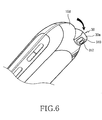
- the camera lens housing 30 comprises a lens 310 and a flash unit 312 adjacent to the lens 310, both of which are mounted on an outer surface in an exposed manner.
- the camera lens housing 30 is rotatably mounted.
- a rotational axis of the camera lens housing 30 is perpendicular to the longitudinal direction in which the bi-directional sliding body 20 slides.
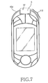
- the second section 112 is formed with an opening 32, in which the camera lens housing 30 is rotatably received.
- the opening 32 takes a form of a slot S which passes through the second section 112. Therefore, a photograph can be taken of a subject through the lens 310, wherein the subject is oriented toward any one of the top, front or bottom surfaces 10d, 10a, or 10c of the phone body 10.
- the portable terminal when the bi-directional sliding body 20 slides to cover the first section 110, the portable terminal is automatically converted into a camera photographing mode. This is preferably realized using a separate proximity sensor, which is not shown in the drawings. Further, even when the bi-directional sliding body 20 is closed onto the phone body 10 (see FIG. 6), a desired subject can be photographed by rotating the camera lens housing 30.
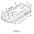
- the portable terminal according to the present invention is designed so that a linear movement is carried out while a top surface 40a of the phone body 40 faces a bottom surface 50b of the bi-directional sliding body 50, and thus either one side or the other of the top surface 40a of the phone body 40 is partially opened to a predetermined extent according to the longitudinal direction in which the bi-directional sliding body 50 moves.
- the phone body 40 includes a first section 410 which is located on one side of the top surface 40a thereof and within which a plurality of first keys 401 are mounted, and a second section 412 which is located on the other side of the top surface 40a thereof spaced apart from the first section 410 and within which a camera lens housing 60 is mounted.
- the bi-directional sliding body 50 has lateral sides, one 50c of which is provided with a plurality of second keys 504.
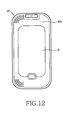
- the phone body 40 has a bottom surface 40b on which a battery pack B is mounted as shown in FIG. 12.
- the bi-directional sliding body 50 includes a speaker 501, a display unit 502 and a plurality of third keys 503, all of which are provided on a top surface 50a thereof.
- the bi-directional sliding body 50 When moved toward the second section 412, the bi-directional sliding body 50 opens the first section 410 to expose the first keys 401. By contrast, when moved toward the first section 410, the bi-directional sliding body 50 opens the second section 412 to expose the camera lens housing 60. These states are shown in FIGs. 9 and 10, respectively.
- the camera lens housing 60 comprises a lens 601 and a flash unit 602 adjacent to the lens 601, both of which are mounted and exposed on an outer surface thereof.
- the camera lens housing 60 is rotatably mounted.
- a rotational axis of the camera lens housing 60 is perpendicular to the longitudinal direction in which the bi-directional sliding body 50 slides.
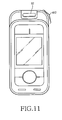
- FIG. 11 shows a state with a camera lens housing removed from the phone body.
- the second section 412 is formed with an opening 62, in which the camera lens housing 60 is rotatably received.
- the opening 62 is formed as a receiving hole. Therefore, the camera lens housing 60 is designed to rotate about a hinge axis in the receiving hole.
- a photograph can be taken of a desired subject through the lens 601 which is oriented toward any one of the top and bottom surfaces 40a and 40b of the phone body 40.
- the portable terminal when the bi-directional sliding body 50 is moved toward the first section 410, the portable terminal is automatically converted into a camera photographing mode. This is preferably realized using a separate proximity sensor, which is not shown in the drawings. Further, even when the bi-directional sliding body 50 is closed onto the phone body 40, a desired subject can be photographed by rotating the camera lens housing 60.
- the bi-directional sliding body functions to protect the keys disposed on the first section 410 of the phone body 40 as well as the camera lens housing 60 disposed on the second section 412 from conditions of an external environment.
- the present invention employs a construction in that the bi-directional sliding body is mounted on the phone body, so that it is possible to efficiently use the lens of the camera lens housing and to protect the lens from the external environment.
- the present invention is designed to allow the bi-directional sliding body to selectively move in either longitudinal direction by push action from a user's finger, so that manipulation of the keys or photographing by the lens can be selected.
Abstract
Description
- The present invention generally relates to a portable terminal such as a cellular phone, a PDA (Personal Digital Assistant), an HHP (Hand Held Phone) or the like, and more particularly to a bi-directional sliding-type portable terminal capable of sliding in either direction.
- In general, a "portable communication device" means an electronic device which a user can carry with him/her to perform wireless communication with a desired partner. In consideration of portability, design of such a portable terminal has tended not only toward compactness, slimness and lightness, but also toward providing multimedia capabilities to allow the user to pursue more various functions. In particular, future portable terminals will be not only used for many functions and purposes despite compactness and lightness, but also be modified to be suitable for functioning in a multimedia environment and for providing internet access and functions. Additionally, such portable terminals may be used by men and women, young and old, anywhere in the world.
- Conventional portable terminals may be classified into various types according to their appearance, such as bar-type portable terminals, flip-type portable terminals, and folder-type portable terminals. The bar-type portable terminal has a single housing shaped like a bar. The flip-type portable terminal has a flip which is pivotably mounted to a bar-shaped housing by a hinge unit. The folder-type portable terminal has a folder coupled to a single bar-shaped housing by a hinge unit in such a manner that the folder can be rotated in order to be folded to or unfolded from the housing.
- Further, portable terminals may be classified as neck wearable type terminals and wrist wearable type terminals, according to the position at or the way in which a user puts on the terminal. The neck wearable type terminal is one which a user wears around the neck using a lanyard or string, while the wrist wearable type terminal is one which a user wears around the wrist.
- Additionally, portable terminals may be classified as rotation-type terminals and sliding-type terminals according to ways of opening and closing the terminals. In the rotation-type portable terminal, two housings are coupled to each other in a manner that one housing rotates to be opened or closed relative to the other while facing each other. In the sliding-type portable terminal, two housings are coupled to each other in a manner that one housing slides to be opened or closed relative to the other. The various classifications of portable terminals are easily understood by those skilled in the art.
- Further, each of the conventional portable terminals enumerated above has been converted so as to allow a voice communication as well as a high-speed data communication. That is, as consumer demands have increased, various services have been provided using wireless communication technology for transceiving data at a high speed.
- It is a present tendency that a camera lens is mounted to the portable terminal, and that it is possible to transmit image signals and the like.
- Meanwhile, present portable terminals are provided with an embedded or external camera lens module. Therefore, it is possible to perform image communication with a desired partner or to photograph a desired subject.
- However, when the conventional portable terminals are provided with an external camera lens module, the risk is always taken of losing the camera lens module. Further, when the conventional portable terminals are provided with an embedded camera lens module, a lens of the camera lens module is always exposed to an external environment, allowing foreign materials to easily invade and deteriorate the lens, thus deteriorating the quality of photographed images.EPO - Munich 69
- Accordingly, the present invention has been made to solve the above-mentioned problems occurring in the prior art, and an object of the present invention is to provide a bi-directional sliding-type portable terminal mounting a bi-directional sliding body on a phone body in order to use a camera lens in a more efficient manner.
- It is another object of the present invention to provide a bi-directional sliding-type portable terminal allowing fabrication in a compact size.
- In order to accomplish these objects, according to the present invention, there is provided a bi-directional sliding-type portable terminal with the features of claim 1. Advantageous embodiments are disclosed by the sub claims.
- The above and other objects, features and advantages of the present invention will be more apparent from the following detailed description taken in conjunction with the accompanying drawings, in which:
- FIG. 1 is a perspective view of a bi-directional sliding-type portable terminal according to a first preferred embodiment of the present invention;
- FIG. 2 is a perspective view showing a bottom surface of the portable terminal shown in FIG. 1;
- FIG. 3 is a top plan view showing a state in which the bi-directional sliding body of FIG. 1 is moved in one direction, so that keys are exposed;
- FIG. 4 is a side elevation view of FIG. 3;
- FIG. 5 is a top plan view showing a state in which the bi-directional sliding body of FIG. 1 is moved in the other direction, so that a camera lens housing is exposed;
- FIG. 6 is a perspective view showing a state in which the camera lens housing rotates;
- FIG. 7 is a top plan view showing a state in which the camera lens housing shown in FIG. 5 is removed;
- FIG. 8 is a perspective view of a bi-directional sliding-type portable terminal according to a second preferred embodiment of the present invention;
- FIG. 9 is a top plan view showing a state in which the bi-directional sliding body of FIG. 8 is moved in one direction, so that keys are exposed;
- FIG. 10 is a top plan view showing a state in which the bi-directional sliding body of FIG. 8 is moved in the other direction, so that a camera lens housing is exposed;
- FIG. 11 is a top plan view showing a state in which the camera lens housing shown in FIG 10 is removed; and
- FIG. 12 is a plan view showing a bottom surface of the portable terminal shown in FIG 8.
-
- Hereinafter, preferred embodiments of the present invention will be described in detail with reference to the accompanying drawings. In the following description of the present invention, a detailed description of known functions and configurations incorporated herein is omitted to avoid making the subject matter of the present invention unclear.
- As shown in FIGs. 1 to 7, a portable terminal according to a first preferred embodiment of the present invention comprises a
phone body 10, and a bi-directionalsliding body 20 linearly moving on thephone body 10 in a longitudinal direction relative to thephone body 10. - To be more specific, the portable terminal according to the present invention is designed so that a linear movement in either longitudinal direction is carried out while a
top surface 10a of thephone body 10 faces abottom surface 20b of thebi-directional sliding body 20, and thus either one side or the other side of the top surface of thephone body 10 is partially opened to a predetermined extent according to a direction in which thebi-directional sliding body 20 moves. Further, the movement range of thebi-directional sliding body 20 is limited by a stopper (not shown), and particularly to a distance large enough to open all of both sides of thetop surface 10a of thephone body 10. - The
phone body 10 includes a first section 110 (FIG. 3) which is located on one side of thetop surface 10a thereof and within which a plurality offirst keys 102 are mounted, and a second section 112 (FIG. 5) which is located on the other side of thetop surface 10a thereof spaced apart from thefirst section 110 and within which acamera lens housing 30 is mounted. FIG. 3 shows a state in which thefirst section 110 is opened, and FIG. 5 shows a state in which thefirst section 110 is closed. - The
phone body 10 has lateral sides, one 10b of which is provided with a plurality ofsecond keys 120, and abottom surface 10c on which a battery pack B is mounted as shown in FIG. 2. - The bi-directional
sliding body 20 includes aspeaker 210, adisplay unit 212 and a plurality ofthird keys 214, all of which are provided on atop surface 20a thereof. - When moved toward the
second section 112, the bi-directionalsliding body 20 opens thefirst section 110 to expose thefirst keys 102. By contrast, when moved toward thefirst section 110, thebi-directional sliding body 20 opens thesecond section 112 to expose thecamera lens housing 30. During a stand-by time, the first andsecond sections phone body 10 are both covered by thebi-directional sliding body 20. - As shown in FIGs. 5 and 6, the
camera lens housing 30 comprises alens 310 and aflash unit 312 adjacent to thelens 310, both of which are mounted on an outer surface in an exposed manner. Here, thecamera lens housing 30 is rotatably mounted. To this end, a rotational axis of thecamera lens housing 30 is perpendicular to the longitudinal direction in which the bi-directionalsliding body 20 slides. - As shown in FIGs. 5 and 7, the
second section 112 is formed with anopening 32, in which thecamera lens housing 30 is rotatably received. Theopening 32 takes a form of a slot S which passes through thesecond section 112. Therefore, a photograph can be taken of a subject through thelens 310, wherein the subject is oriented toward any one of the top, front orbottom surfaces phone body 10. - Additionally, when the
bi-directional sliding body 20 slides to cover thefirst section 110, the portable terminal is automatically converted into a camera photographing mode. This is preferably realized using a separate proximity sensor, which is not shown in the drawings. Further, even when the bi-directional slidingbody 20 is closed onto the phone body 10 (see FIG. 6), a desired subject can be photographed by rotating thecamera lens housing 30. - As shown in FIGs. 8 to 12, a portable terminal according to a second preferred embodiment of the present invention comprises a
phone body 40, and a bi-directional slidingbody 50 linearly moving on thephone body 40 in either longitudinal direction while facing thephone body 40. The portable terminal according to the present invention is designed so that a linear movement is carried out while atop surface 40a of thephone body 40 faces abottom surface 50b of the bi-directional slidingbody 50, and thus either one side or the other of thetop surface 40a of thephone body 40 is partially opened to a predetermined extent according to the longitudinal direction in which the bi-directional slidingbody 50 moves. - The
phone body 40 includes afirst section 410 which is located on one side of thetop surface 40a thereof and within which a plurality offirst keys 401 are mounted, and asecond section 412 which is located on the other side of thetop surface 40a thereof spaced apart from thefirst section 410 and within which acamera lens housing 60 is mounted. The bi-directional slidingbody 50 has lateral sides, one 50c of which is provided with a plurality ofsecond keys 504. Thephone body 40 has abottom surface 40b on which a battery pack B is mounted as shown in FIG. 12. - The bi-directional sliding
body 50 includes aspeaker 501, adisplay unit 502 and a plurality ofthird keys 503, all of which are provided on atop surface 50a thereof. - When moved toward the
second section 412, the bi-directional slidingbody 50 opens thefirst section 410 to expose thefirst keys 401. By contrast, when moved toward thefirst section 410, the bi-directional slidingbody 50 opens thesecond section 412 to expose thecamera lens housing 60. These states are shown in FIGs. 9 and 10, respectively. - The
camera lens housing 60 comprises alens 601 and aflash unit 602 adjacent to thelens 601, both of which are mounted and exposed on an outer surface thereof. Here, thecamera lens housing 60 is rotatably mounted. To this end, a rotational axis of thecamera lens housing 60 is perpendicular to the longitudinal direction in which the bi-directional slidingbody 50 slides. - FIG. 11 shows a state with a camera lens housing removed from the phone body. As shown in FIG. 11, the
second section 412 is formed with anopening 62, in which thecamera lens housing 60 is rotatably received. Theopening 62 is formed as a receiving hole. Therefore, thecamera lens housing 60 is designed to rotate about a hinge axis in the receiving hole. A photograph can be taken of a desired subject through thelens 601 which is oriented toward any one of the top andbottom surfaces phone body 40. - Additionally, when the bi-directional sliding
body 50 is moved toward thefirst section 410, the portable terminal is automatically converted into a camera photographing mode. This is preferably realized using a separate proximity sensor, which is not shown in the drawings. Further, even when the bi-directional slidingbody 50 is closed onto thephone body 40, a desired subject can be photographed by rotating thecamera lens housing 60. - Further, the bi-directional sliding body functions to protect the keys disposed on the
first section 410 of thephone body 40 as well as thecamera lens housing 60 disposed on thesecond section 412 from conditions of an external environment. - As can seen from the foregoing, the present invention employs a construction in that the bi-directional sliding body is mounted on the phone body, so that it is possible to efficiently use the lens of the camera lens housing and to protect the lens from the external environment. In addition, the present invention is designed to allow the bi-directional sliding body to selectively move in either longitudinal direction by push action from a user's finger, so that manipulation of the keys or photographing by the lens can be selected.
- While the invention has been shown and described with reference to certain preferred embodiments thereof, it will be understood by those skilled in the art that various changes in form and details may be made therein without departing from the spirit and scope of the invention as defined by the appended claims.
Claims (9)
- A bi-directional sliding-type portable terminal comprising:a phone body (10, 40) having a first section (110, 410) which is located on one side of a top surface (10a, 40a) thereof and within which a plurality of keys (102, 401) are mounted, and a second section (112, 412) which is located on the other side of the top surface thereof spaced apart from the first section and within which a camera lens housing (30, 60) is mounted, anda bi-directional sliding body (20, 50) linearly movable on the phone body (10, 40) in a longitudinal direction, wherein moving the bi-directional sliding body (20, 50) toward the second section (112, 412) opens the first section (110, 410) to expose the plurality of keys (102, 401), and moving the bi-directional sliding body (20, 50) toward the first section (110, 410) opens the second section (112, 412) to expose the camera lens housing (30, 60).
- The bi-directional sliding-type portable terminal as claimed in claim 1, wherein the camera lens housing (30, 60) is rotatably mounted.
- The bi-directional sliding-type portable terminal as claimed in claim 1, wherein the camera lens housing (30, 60) is rotabably mounted about a hinge axis perpendicular to the longitudinal direction.
- A bi-directional sliding-type portable terminal according to one of the previous claims, wherein the bi-directional sliding body (20, 50) protects the first keys (102, 401) and the camera lens housing (30, 60) from an external environment when in a state of facing the first keys and the camera lens housing.
- The bi-directional sliding-type portable terminal according to one of the previous claims, characterized in that the camera lens housing (30, 60) comprises a lens (310, 601) and a flash unit (312, 602) adjacent to the lens.
- The bi-directional sliding-type portable terminal according to one of the previous claims, characterized in that an opening (32, 62) is formed in the second section (112, 412) to rotabably receive the camera lens housing (30, 60).
- The bi-directional sliding-type portable terminal according to claim 6, wherein the opening (32) is formed as a slot (S).
- The bi-directional sliding-type portable terminal according to claim 6, wherein the opening (62) is formed as a hole.
- The bi-directional sliding-type portable terminal according to one of the previous claims, wherein the bi-directional sliding body (20, 50) comprises a speaker (210, 501), a display unit (212, 502) adjacent to the speaker and a number of second keys (214, 503) adjacent to the display unit (212, 502), all of which are provided on a top surface (20a, 50a) thereof.
Applications Claiming Priority (2)
| Application Number | Priority Date | Filing Date | Title |
|---|---|---|---|
| KR2003048718 | 2003-07-16 | ||
| KR1020030048718A KR100703495B1 (en) | 2003-07-16 | 2003-07-16 | Bi-directional sliding-type portable phone |
Publications (2)
| Publication Number | Publication Date |
|---|---|
| EP1499094A1 true EP1499094A1 (en) | 2005-01-19 |
| EP1499094B1 EP1499094B1 (en) | 2006-06-21 |
Family
ID=36686681
Family Applications (1)
| Application Number | Title | Priority Date | Filing Date |
|---|---|---|---|
| EP04016888A Active EP1499094B1 (en) | 2003-07-16 | 2004-07-16 | Bi-directional sliding-type portable terminal comprising a camera |
Country Status (5)
| Country | Link |
|---|---|
| US (2) | US7386331B2 (en) |
| EP (1) | EP1499094B1 (en) |
| KR (1) | KR100703495B1 (en) |
| CN (1) | CN100488210C (en) |
| DE (1) | DE602004001295T2 (en) |
Cited By (4)
| Publication number | Priority date | Publication date | Assignee | Title |
|---|---|---|---|---|
| EP1691532A2 (en) | 2003-12-09 | 2006-08-16 | LG Electronics Inc. | Slide type portable communication terminal |
| EP1760996A2 (en) | 2005-08-29 | 2007-03-07 | Samsung Electronics Co., Ltd. | Slide assembly for a portable terminal |
| WO2011149381A1 (en) * | 2010-05-24 | 2011-12-01 | Mikheyev Alexander Alexandrovich | Photo-video camera on a mobile telephone (variants) |
| EP3661172A1 (en) * | 2018-11-29 | 2020-06-03 | Samsung Electronics Co., Ltd. | Rotation of camera for sliding phone dependent on operational mode |
Families Citing this family (67)
| Publication number | Priority date | Publication date | Assignee | Title |
|---|---|---|---|---|
| KR100703495B1 (en) * | 2003-07-16 | 2007-04-03 | 삼성전자주식회사 | Bi-directional sliding-type portable phone |
| US7441058B1 (en) * | 2006-09-11 | 2008-10-21 | Apple Inc. | Method and system for controlling an accessory having a tuner |
| CN2706974Y (en) * | 2004-06-18 | 2005-06-29 | 鸿富锦精密工业(深圳)有限公司 | Cellphone with night visual function |
| TWI255125B (en) * | 2004-09-08 | 2006-05-11 | Benq Corp | Electronic apparatus with cover for protecting image capture device |
| KR100703510B1 (en) * | 2004-12-21 | 2007-04-03 | 삼성전자주식회사 | Sliding type portable device with optical zoom lens assembly |
| ATE410878T1 (en) * | 2005-02-11 | 2008-10-15 | Nokia Corp | HAND-PORTABLE MULTIPLE-MODE ELECTRONIC DEVICE |
| WO2006087599A1 (en) * | 2005-02-18 | 2006-08-24 | Nokia Corporation | A portable electronic device for capturing images |
| US7492891B2 (en) | 2005-03-03 | 2009-02-17 | Nokia Corporation | Mobile electronic device having relocatable display element |
| KR100689530B1 (en) * | 2005-03-16 | 2007-03-02 | 삼성전자주식회사 | Mobile phone with replaceable module |
| WO2006108153A2 (en) | 2005-04-06 | 2006-10-12 | Nokia Corporation | Digital camera module for mobile communication device |
| KR100692774B1 (en) * | 2005-04-27 | 2007-03-12 | 주식회사 팬택 | Slide module and slide type mobile communication terminal having the same |
| US7531773B2 (en) | 2005-09-08 | 2009-05-12 | Flextronics Ap, Llc | Auto-focus and zoom module having a lead screw with its rotation results in translation of an optics group |
| US20070161418A1 (en) * | 2006-01-12 | 2007-07-12 | Inventec Corporation | Sliding cover of smartphone |
| US8374656B2 (en) * | 2006-05-24 | 2013-02-12 | Lg Electronics Inc. | Mobile communication device and method for controlling the same |
| US8112128B2 (en) | 2006-08-31 | 2012-02-07 | Flextronics Ap, Llc | Discreetly positionable camera housing |
| USD580387S1 (en) | 2007-01-05 | 2008-11-11 | Apple Inc. | Electronic device |
| USD558758S1 (en) | 2007-01-05 | 2008-01-01 | Apple Inc. | Electronic device |
| KR101122092B1 (en) * | 2006-11-28 | 2012-06-14 | 엘지전자 주식회사 | A mobile telecommunication device having a scroll input device and a input signal precessing method |
| USD898736S1 (en) | 2007-01-05 | 2020-10-13 | Apple Inc. | Electronic device |
| JP2010525413A (en) * | 2007-04-24 | 2010-07-22 | フレックストロニクス エーピー エルエルシー | Auto focus / zoom module using wafer level optics |
| WO2008133943A1 (en) * | 2007-04-24 | 2008-11-06 | Flextronics Ap Llc | Small form factor modules using wafer level optics with bottom cavity and flip chip assembly |
| US8083421B2 (en) * | 2007-05-07 | 2011-12-27 | Flextronics Ap, Llc | AF/zoom shutter with two blades function |
| US7825985B2 (en) | 2007-07-19 | 2010-11-02 | Flextronics Ap, Llc | Camera module back-focal length adjustment method and ultra compact components packaging |
| JP5009099B2 (en) * | 2007-08-30 | 2012-08-22 | ソニーモバイルコミュニケーションズ, エービー | Portable information terminal |
| USD602486S1 (en) | 2007-08-31 | 2009-10-20 | Apple Inc. | Electronic device |
| USD957385S1 (en) | 2007-08-31 | 2022-07-12 | Apple Inc. | Electronic device |
| US8488046B2 (en) | 2007-12-27 | 2013-07-16 | Digitaloptics Corporation | Configurable tele wide module |
| USD602015S1 (en) | 2008-04-07 | 2009-10-13 | Apple Inc. | Electronic device |
| USD602016S1 (en) | 2008-04-07 | 2009-10-13 | Apple Inc. | Electronic device |
| USD615083S1 (en) | 2008-04-07 | 2010-05-04 | Apple Inc. | Electronic device |
| USD602017S1 (en) | 2008-09-05 | 2009-10-13 | Apple Inc. | Electronic device |
| KR20100053222A (en) * | 2008-11-12 | 2010-05-20 | 삼성전자주식회사 | Slide type portable terminal |
| US8983639B2 (en) | 2008-12-14 | 2015-03-17 | Apple Inc. | Techniques for facilitating interoperation between a host device and a digital RF tuner accessory |
| CN101750849A (en) * | 2008-12-22 | 2010-06-23 | 深圳富泰宏精密工业有限公司 | Electronic device |
| US20100331062A1 (en) * | 2009-06-30 | 2010-12-30 | Nokia Corporation | Microslide |
| US8238893B2 (en) * | 2009-09-03 | 2012-08-07 | Apple Inc. | Techniques for controlling a portable media device having a radio frequency tuner |
| USD642563S1 (en) | 2010-08-16 | 2011-08-02 | Apple Inc. | Electronic device |
| USD680109S1 (en) | 2010-09-01 | 2013-04-16 | Apple Inc. | Electronic device with graphical user interface |
| US10009528B2 (en) | 2011-02-24 | 2018-06-26 | Nan Chang O-Film Optoelectronics Technology Ltd | Autofocus camera module packaging with circuitry-integrated actuator system |
| US8545114B2 (en) | 2011-03-11 | 2013-10-01 | Digitaloptics Corporation | Auto focus-zoom actuator or camera module contamination reduction feature with integrated protective membrane |
| US8982267B2 (en) | 2011-07-27 | 2015-03-17 | Flextronics Ap, Llc | Camera module with particle trap |
| USD688060S1 (en) * | 2011-09-09 | 2013-08-20 | Panasonic Avionics Corporation | Integrated user interface system for user seat |
| CN202231759U (en) * | 2011-09-15 | 2012-05-23 | 中兴通讯股份有限公司 | Mobile phone |
| USD684571S1 (en) | 2012-09-07 | 2013-06-18 | Apple Inc. | Electronic device |
| USD707223S1 (en) | 2012-05-29 | 2014-06-17 | Apple Inc. | Electronic device |
| USD681032S1 (en) | 2012-09-11 | 2013-04-30 | Apple Inc. | Electronic device |
| USD717777S1 (en) | 2012-09-27 | 2014-11-18 | Incipio Technologies, Inc. | Case |
| US9325816B2 (en) * | 2013-08-01 | 2016-04-26 | Htc Corporation | Displaying method and portable device |
| USD748621S1 (en) | 2013-09-09 | 2016-02-02 | Apple Inc. | Electronic device |
| USD754125S1 (en) | 2013-09-09 | 2016-04-19 | Apple Inc. | Electronic device |
| USD753101S1 (en) | 2013-09-09 | 2016-04-05 | Apple Inc. | Electronic device |
| USD747310S1 (en) | 2013-09-09 | 2016-01-12 | Apple Inc. | Electronic device |
| USD760217S1 (en) | 2013-09-09 | 2016-06-28 | Apple Inc. | Electronic device |
| USD748091S1 (en) | 2013-09-09 | 2016-01-26 | Apple Inc. | Electronic device |
| USD845294S1 (en) | 2014-05-05 | 2019-04-09 | Apple Inc. | Housing for an electronic device with surface ornamentation |
| TWD172435S (en) * | 2014-10-08 | 2015-12-11 | 鴻海精密工業股份有限公司 | Part of mobile phone |
| US9894265B1 (en) * | 2016-12-23 | 2018-02-13 | Blackberry Limited | Electronic device and method of controlling same for capturing digital images |
| US10681193B2 (en) * | 2017-10-13 | 2020-06-09 | Guangdong Oppo Mobile Telecommunications Corp., Ltd | Mobile terminal |
| USD924868S1 (en) | 2018-04-23 | 2021-07-13 | Apple Inc. | Electronic device |
| CN108600449B (en) * | 2018-04-23 | 2020-12-29 | 京东方科技集团股份有限公司 | Display device |
| JP1621612S (en) * | 2018-05-25 | 2019-01-07 | ||
| USD964985S1 (en) | 2018-07-13 | 2022-09-27 | Apple Inc. | Electronic device |
| CN111107260A (en) * | 2018-10-25 | 2020-05-05 | 北京小米移动软件有限公司 | Quick shooting method, equipment and readable storage medium |
| CN111107262B (en) * | 2018-10-25 | 2022-01-11 | 北京小米移动软件有限公司 | Quick shooting method, equipment and readable storage medium |
| KR102631112B1 (en) * | 2019-04-30 | 2024-01-30 | 삼성전자 주식회사 | Electric device including rotating camera |
| KR20210020564A (en) * | 2019-08-16 | 2021-02-24 | 삼성전자주식회사 | Electronic device including slide body having rotation type camera module |
| USD974352S1 (en) | 2019-11-22 | 2023-01-03 | Apple Inc. | Electronic device |
Citations (5)
| Publication number | Priority date | Publication date | Assignee | Title |
|---|---|---|---|---|
| WO1996038762A1 (en) * | 1995-05-29 | 1996-12-05 | Behruz Vazvan | Multi-functional portable electronic device |
| EP0804009A2 (en) * | 1996-04-26 | 1997-10-29 | Mitsubishi Denki Kabushiki Kaisha | Mobile communication terminal equipment and portable electronic apparatus |
| DE19806508A1 (en) * | 1998-02-17 | 1999-08-26 | Harsch | Hand-held mobile video telephone for audio or combined audio and visual communications |
| US20030036365A1 (en) * | 2001-08-16 | 2003-02-20 | Nec Corporation | Portable communications terminal with camera capable of taking pictures |
| GB2381988A (en) * | 2001-10-03 | 2003-05-14 | Nec Corp | Slide type mobile phone |
Family Cites Families (6)
| Publication number | Priority date | Publication date | Assignee | Title |
|---|---|---|---|---|
| US6208874B1 (en) * | 1998-11-02 | 2001-03-27 | Ericsson Inc. | Telephone assembly with automatic antenna adjustment |
| KR20020078872A (en) * | 2001-04-11 | 2002-10-19 | 김영호 | Cellular Phone having a liquid crystal display for Screen Communication |
| JP2003204383A (en) * | 2001-10-26 | 2003-07-18 | Nec Corp | Portable telephone |
| KR20020041354A (en) * | 2002-03-06 | 2002-06-01 | 황용안 | Mamber's call-ID witness type internet site login service system |
| KR100703495B1 (en) * | 2003-07-16 | 2007-04-03 | 삼성전자주식회사 | Bi-directional sliding-type portable phone |
| KR100608726B1 (en) * | 2003-12-09 | 2006-08-04 | 엘지전자 주식회사 | Sliding type mobile phone both up and down direction |
-
2003
- 2003-07-16 KR KR1020030048718A patent/KR100703495B1/en active IP Right Grant
-
2004
- 2004-06-17 US US10/870,812 patent/US7386331B2/en active Active
- 2004-07-16 CN CNB2004100636812A patent/CN100488210C/en active Active
- 2004-07-16 DE DE602004001295T patent/DE602004001295T2/en active Active
- 2004-07-16 EP EP04016888A patent/EP1499094B1/en active Active
-
2008
- 2008-06-10 US US12/136,418 patent/US8090420B2/en active Active
Patent Citations (5)
| Publication number | Priority date | Publication date | Assignee | Title |
|---|---|---|---|---|
| WO1996038762A1 (en) * | 1995-05-29 | 1996-12-05 | Behruz Vazvan | Multi-functional portable electronic device |
| EP0804009A2 (en) * | 1996-04-26 | 1997-10-29 | Mitsubishi Denki Kabushiki Kaisha | Mobile communication terminal equipment and portable electronic apparatus |
| DE19806508A1 (en) * | 1998-02-17 | 1999-08-26 | Harsch | Hand-held mobile video telephone for audio or combined audio and visual communications |
| US20030036365A1 (en) * | 2001-08-16 | 2003-02-20 | Nec Corporation | Portable communications terminal with camera capable of taking pictures |
| GB2381988A (en) * | 2001-10-03 | 2003-05-14 | Nec Corp | Slide type mobile phone |
Cited By (8)
| Publication number | Priority date | Publication date | Assignee | Title |
|---|---|---|---|---|
| EP1691532A2 (en) | 2003-12-09 | 2006-08-16 | LG Electronics Inc. | Slide type portable communication terminal |
| EP1691532A3 (en) * | 2003-12-09 | 2006-12-13 | LG Electronics Inc. | Slide type portable communication terminal |
| EP1760996A2 (en) | 2005-08-29 | 2007-03-07 | Samsung Electronics Co., Ltd. | Slide assembly for a portable terminal |
| EP1760996A3 (en) * | 2005-08-29 | 2007-04-18 | Samsung Electronics Co., Ltd. | Slide assembly for a portable terminal |
| US7747298B2 (en) | 2005-08-29 | 2010-06-29 | Samsung Electronics Co., Ltd. | Sliding device for portable terminal |
| WO2011149381A1 (en) * | 2010-05-24 | 2011-12-01 | Mikheyev Alexander Alexandrovich | Photo-video camera on a mobile telephone (variants) |
| EP3661172A1 (en) * | 2018-11-29 | 2020-06-03 | Samsung Electronics Co., Ltd. | Rotation of camera for sliding phone dependent on operational mode |
| US10686971B1 (en) | 2018-11-29 | 2020-06-16 | Samsung Electronics Co., Ltd. | Electronic device including a camera capable of being a front camera and a rear camera and an operating method thereof |
Also Published As
| Publication number | Publication date |
|---|---|
| EP1499094B1 (en) | 2006-06-21 |
| CN100488210C (en) | 2009-05-13 |
| KR100703495B1 (en) | 2007-04-03 |
| DE602004001295D1 (en) | 2006-08-03 |
| DE602004001295T2 (en) | 2006-11-02 |
| US20080242381A1 (en) | 2008-10-02 |
| US8090420B2 (en) | 2012-01-03 |
| CN1578342A (en) | 2005-02-09 |
| KR20050009412A (en) | 2005-01-25 |
| US7386331B2 (en) | 2008-06-10 |
| US20050014538A1 (en) | 2005-01-20 |
Similar Documents
| Publication | Publication Date | Title |
|---|---|---|
| US7386331B2 (en) | Bi-directional sliding-type portable terminal | |
| US7480524B2 (en) | Portable communication terminal in slant positions for displaying information | |
| US7587225B2 (en) | Sliding-folding type portable communication apparatus | |
| US20060203124A1 (en) | Folder-type portable apparatus | |
| US7373187B2 (en) | Portable digital communication apparatus having sliding/rotational hinge means | |
| US7443979B2 (en) | Portable communication terminal having a housing capable of both sliding and swinging | |
| EP1667409A1 (en) | Foldable phone with slidable housing to protect display and camera | |
| US20060135227A1 (en) | Sliding/folding combination type portable digital communication apparatus and hinge unit thereof | |
| KR100640342B1 (en) | Swing-type portable digital communication device with step-compensated mechanism | |
| US7450173B2 (en) | Sliding-type portable digital communication apparatus | |
| KR100539934B1 (en) | Portable communication apparatus | |
| EP1501261A2 (en) | Dual-speaker folder type portable terminal | |
| KR100689472B1 (en) | Portable communication device | |
| KR100703509B1 (en) | Sliding type portable telephone with game function | |
| KR100663504B1 (en) | Portable digital communication device with improved grip | |
| EP1424837A1 (en) | Portable communication apparatus having data input expandability | |
| KR100663501B1 (en) | Portable digital communication device | |
| KR100469855B1 (en) | Portable communication device | |
| KR101119342B1 (en) | Mobile phone with folding-type receiver | |
| KR200364949Y1 (en) | Folder-type portable apparatus | |
| KR20060093434A (en) | Portable communication device porvided with camera lens having enlarged objects shooting range | |
| KR20050023896A (en) | Sliding/swing type portable communication device | |
| KR20050117114A (en) | Portable digital communication device | |
| KR20060055905A (en) | Portable digital communication device with two-hinge axis camera lens | |
| KR20050010577A (en) | Portable communication device |
Legal Events
| Date | Code | Title | Description |
|---|---|---|---|
| PUAI | Public reference made under article 153(3) epc to a published international application that has entered the european phase |
Free format text: ORIGINAL CODE: 0009012 |
|
| 17P | Request for examination filed |
Effective date: 20040716 |
|
| AK | Designated contracting states |
Kind code of ref document: A1 Designated state(s): AT BE BG CH CY CZ DE DK EE ES FI FR GB GR HU IE IT LI LU MC NL PL PT RO SE SI SK TR |
|
| AX | Request for extension of the european patent |
Extension state: AL HR LT LV MK |
|
| 17Q | First examination report despatched |
Effective date: 20050504 |
|
| AKX | Designation fees paid |
Designated state(s): DE FR GB |
|
| GRAP | Despatch of communication of intention to grant a patent |
Free format text: ORIGINAL CODE: EPIDOSNIGR1 |
|
| GRAS | Grant fee paid |
Free format text: ORIGINAL CODE: EPIDOSNIGR3 |
|
| GRAA | (expected) grant |
Free format text: ORIGINAL CODE: 0009210 |
|
| AK | Designated contracting states |
Kind code of ref document: B1 Designated state(s): DE FR GB |
|
| REG | Reference to a national code |
Ref country code: GB Ref legal event code: FG4D |
|
| REF | Corresponds to: |
Ref document number: 602004001295 Country of ref document: DE Date of ref document: 20060803 Kind code of ref document: P |
|
| ET | Fr: translation filed | ||
| PLBE | No opposition filed within time limit |
Free format text: ORIGINAL CODE: 0009261 |
|
| STAA | Information on the status of an ep patent application or granted ep patent |
Free format text: STATUS: NO OPPOSITION FILED WITHIN TIME LIMIT |
|
| 26N | No opposition filed |
Effective date: 20070322 |
|
| REG | Reference to a national code |
Ref country code: FR Ref legal event code: PLFP Year of fee payment: 13 |
|
| REG | Reference to a national code |
Ref country code: FR Ref legal event code: PLFP Year of fee payment: 14 |
|
| REG | Reference to a national code |
Ref country code: FR Ref legal event code: PLFP Year of fee payment: 15 |
|
| PGFP | Annual fee paid to national office [announced via postgrant information from national office to epo] |
Ref country code: FR Payment date: 20200624 Year of fee payment: 17 |
|
| PGFP | Annual fee paid to national office [announced via postgrant information from national office to epo] |
Ref country code: GB Payment date: 20200624 Year of fee payment: 17 |
|
| GBPC | Gb: european patent ceased through non-payment of renewal fee |
Effective date: 20210716 |
|
| PG25 | Lapsed in a contracting state [announced via postgrant information from national office to epo] |
Ref country code: GB Free format text: LAPSE BECAUSE OF NON-PAYMENT OF DUE FEES Effective date: 20210716 |
|
| PG25 | Lapsed in a contracting state [announced via postgrant information from national office to epo] |
Ref country code: FR Free format text: LAPSE BECAUSE OF NON-PAYMENT OF DUE FEES Effective date: 20210731 |
|
| PGFP | Annual fee paid to national office [announced via postgrant information from national office to epo] |
Ref country code: DE Payment date: 20230620 Year of fee payment: 20 |