EP1487535B1 - Electrode structures for use in cardiovascular reflex control - Google Patents
Electrode structures for use in cardiovascular reflex control Download PDFInfo
- Publication number
- EP1487535B1 EP1487535B1 EP03716888A EP03716888A EP1487535B1 EP 1487535 B1 EP1487535 B1 EP 1487535B1 EP 03716888 A EP03716888 A EP 03716888A EP 03716888 A EP03716888 A EP 03716888A EP 1487535 B1 EP1487535 B1 EP 1487535B1
- Authority
- EP
- European Patent Office
- Prior art keywords
- electrode
- base
- activation device
- electrodes
- carotid
- Prior art date
- Legal status (The legal status is an assumption and is not a legal conclusion. Google has not performed a legal analysis and makes no representation as to the accuracy of the status listed.)
- Expired - Lifetime
Links
Images


Classifications
-
- A—HUMAN NECESSITIES
- A61—MEDICAL OR VETERINARY SCIENCE; HYGIENE
- A61N—ELECTROTHERAPY; MAGNETOTHERAPY; RADIATION THERAPY; ULTRASOUND THERAPY
- A61N1/00—Electrotherapy; Circuits therefor
- A61N1/02—Details
- A61N1/04—Electrodes
- A61N1/05—Electrodes for implantation or insertion into the body, e.g. heart electrode
- A61N1/0551—Spinal or peripheral nerve electrodes
- A61N1/0556—Cuff electrodes
-
- A—HUMAN NECESSITIES
- A61—MEDICAL OR VETERINARY SCIENCE; HYGIENE
- A61N—ELECTROTHERAPY; MAGNETOTHERAPY; RADIATION THERAPY; ULTRASOUND THERAPY
- A61N1/00—Electrotherapy; Circuits therefor
- A61N1/18—Applying electric currents by contact electrodes
- A61N1/32—Applying electric currents by contact electrodes alternating or intermittent currents
- A61N1/36—Applying electric currents by contact electrodes alternating or intermittent currents for stimulation
- A61N1/3605—Implantable neurostimulators for stimulating central or peripheral nerve system
- A61N1/3606—Implantable neurostimulators for stimulating central or peripheral nerve system adapted for a particular treatment
- A61N1/36114—Cardiac control, e.g. by vagal stimulation
- A61N1/36117—Cardiac control, e.g. by vagal stimulation for treating hypertension
-
- A—HUMAN NECESSITIES
- A61—MEDICAL OR VETERINARY SCIENCE; HYGIENE
- A61N—ELECTROTHERAPY; MAGNETOTHERAPY; RADIATION THERAPY; ULTRASOUND THERAPY
- A61N1/00—Electrotherapy; Circuits therefor
- A61N1/18—Applying electric currents by contact electrodes
- A61N1/32—Applying electric currents by contact electrodes alternating or intermittent currents
- A61N1/36—Applying electric currents by contact electrodes alternating or intermittent currents for stimulation
- A61N1/372—Arrangements in connection with the implantation of stimulators
- A61N1/37205—Microstimulators, e.g. implantable through a cannula
-
- A—HUMAN NECESSITIES
- A61—MEDICAL OR VETERINARY SCIENCE; HYGIENE
- A61N—ELECTROTHERAPY; MAGNETOTHERAPY; RADIATION THERAPY; ULTRASOUND THERAPY
- A61N1/00—Electrotherapy; Circuits therefor
- A61N1/18—Applying electric currents by contact electrodes
- A61N1/32—Applying electric currents by contact electrodes alternating or intermittent currents
- A61N1/36—Applying electric currents by contact electrodes alternating or intermittent currents for stimulation
- A61N1/372—Arrangements in connection with the implantation of stimulators
- A61N1/37211—Means for communicating with stimulators
- A61N1/37217—Means for communicating with stimulators characterised by the communication link, e.g. acoustic or tactile
- A61N1/37223—Circuits for electromagnetic coupling
Definitions
- Embodiments of the present invention generally relate to medical devices for the treatment and/or management of cardiovascular and renal disorders. Specifically, embodiments of the present invention relate to devices for controlling the baroreflex system for the treatment and/or management of cardiovascular and renal disorders and their underlying causes and conditions.
- Cardiovascular disease is a major contributor to patient illness and mortality. It also is a primary driver of health care expenditure, costing more than $326 billion each year in the United States.
- Hypertension or high blood pressure, is a major cardiovascular disorder that is estimated to affect over 50 million people in the United Sates alone. Of those with hypertension, it is reported that fewer than 30% have their blood pressure under control.
- Hypertension is a leading cause of heart failure and stroke. It is the primary cause of death in over 42,000 patients per year and is listed as a primary or contributing cause of death in over 200,000 patients per year in the U.S. Accordingly, hypertension is a serious health problem demanding significant research and development for the treatment thereof.
- Hypertension occurs when the body's smaller blood vessels (arterioles) constrict, causing an increase in blood pressure. Because the blood vessels constrict, the heart must work harder to maintain blood flow at the higher pressures. Although the body may tolerate short periods of increased blood pressure, sustained hypertension may eventually result in damage to multiple body organs, including the kidneys, brain, eyes and other tissues, causing a variety of maladies associated therewith. The elevated blood pressure may also damage the lining of the blood vessels, accelerating the process of atherosclerosis and increasing the likelihood that a blood clot may develop. This could lead to a heart attack and/or stroke. Sustained high blood pressure may eventually result in an enlarged and damaged heart (hypertrophy), which may lead to heart failure.
- Heart failure is the final common expression of a variety of cardiovascular disorders, including ischemic heart disease. It is characterized by an inability of the heart to pump enough blood to meet the body's needs and results in fatigue, reduced exercise capacity and poor survival. It is estimated that approximately 5,000,000 people in the United States suffer from heart failure, directly leading to 39,000 deaths per year and contributing to another 225,000 deaths per year. It is also estimated that greater than 400,000 new cases of heart failure are diagnosed each year. Heart failure accounts for over 900,000 hospital admissions annually, and is the most common discharge diagnosis in patients over the age of 65 years. It has been reported that the cost of treating heart failure in the United States exceeds $20 billion annually. Accordingly, heart failure is also a serious health problem demanding significant research and development for the treatment and/or management thereof.
- Heart failure results in the activation of a number of body systems to compensate for the heart's inability to pump sufficient blood. Many of these responses are mediated by an increase in the level of activation of the sympathetic nervous system, as well as by activation of multiple other neurohormonal responses.
- this sympathetic nervous system activation signals the heart to increase heart rate and force of contraction to increase the cardiac output; it signals the kidneys to expand the blood volume by retaining sodium and water; and it signals the arterioles to constrict to elevate the blood pressure.
- the cardiac, renal and vascular responses increase the workload of the heart, further accelerating myocardial damage and exacerbating the heart failure state. Accordingly, it is desirable to reduce the level of sympathetic nervous system activation in order to stop or at least minimize this vicious cycle and thereby treat or manage the heart failure.
- vasodilators to reduce the blood pressure and ease the workload of the heart
- diuretics to reduce fluid overload
- inhibitors and blocking agents of the body's neurohormonal responses and other medicaments.
- Heart transplantation has been proposed for patients who suffer from severe, refractory heart failure.
- an implantable medical device such as a ventricular assist device (VAD) may be implanted in the chest to increase the pumping action of the heart.
- a ventricular assist device VAD
- IABP intra-aortic balloon pump
- Other surgical procedures are available as well.
- the wall of the carotid sinus a structure at the bifurcation of the common carotid arteries, contains stretch receptors (baroreceptors) that are sensitive to the blood pressure. These receptors send signals via the carotid sinus nerve to the brain, which in turn regulates the cardiovascular system to maintain normal blood pressure (the baroreflex), in part through activation of the sympathetic nervous system.
- Electrical stimulation of the carotid sinus nerve has previously been proposed to reduce blood pressure and the workload of the heart in the treatment of high blood pressure and angina.
- U.S. Patent No. 6,073,048 to Kieval et al discloses a baroreflex modulation system and method for stimulating the baroreflex arc based on various cardiovascular and pulmonary parameters.
- each of the therapies has its own disadvantages.
- drug therapy is often incompletely effective. Some patients may be unresponsive (refractory) to medical therapy. Drugs often have unwanted side effects and may need to be given in complex regimens. These and other factors contribute to poor patient compliance with medical therapy. Drug therapy may also be expensive, adding to the health care costs associated with these disorders.
- surgical approaches are very costly, may be associated with significant patient morbidity and mortality and may not alter the natural history of the disease. Baropacing also has not gained acceptance.
- Several problems with electrical carotid sinus nerve stimulation have been reported in the medical literature. These include the invasiveness of the surgical procedure to implant the nerve electrodes, and postoperative pain in the jaw, throat, face and head during stimulation.
- Document WO 02/26314 describes a baroreceptor activation device positionable near a baroreceptor, preferably a baroreceptor located in the carotid sinus.
- a control system may be used to modulate the baroreceptor activation device.
- the control system may utilize an algorithm defining a stimulus regimen which promotes long term efficacy and reduces power requirements/consumption.
- a mapping method permits the baroreceptor activation device to be precisely located to maximize therapeutic efficacy.
- the baroreceptor activation device may utilize electrodes to activate the baroreceptors.
- the electrodes may be adapted for connection to the carotid arteries at or near the carotid sinus, and may be designed to minimize extraneous tissue stimulation.
- Document WO 03/018107 describes an electrode assembly to be installed on a patient's nerve has a thin, flexible, electrically insulating circumneural carrier with a split circumferential configuration longitudinally attached to a lead at the distal end thereof.
- the carrier possesses circumferential resiliency and has at least one flexible, elastic electrode secured to the underside thereof and electrically connected to an electrical conductor in said lead.
- a fastener serves to close the split configuration of the carrier to prevent separation from the nerve after installation of the electrode assembly onto the nerve.
- the devices described herein reduce excessive blood pressure, sympathetic nervous system activation and neurohormonal activation, thereby minimizing their deleterious effects on the heart, vasculature and other organs and tissues.
- Described herein are systems for treating a patient by inducing a baroreceptor signal to effect a change in the baroreflex system (e. g., reduced heart rate, reduced blood pressure, etc.).
- the baroreceptor signal is activated or otherwise modified by selectively activating baroreceptors.
- the system described herein utilizes a baroreceptor activation device positioned near a baroreceptor in the carotid sinus, aortic arch, heart, common carotid arteries, subclavian arteries, and/or brachiocephalic artery.
- the baroreceptor activation device is located in the right and/or left carotid sinus (near the bifurcation of the common carotid artery) and/or the aortic arch.
- the carotid sinus location is described with reference to the carotid sinus location.
- the baroreceptor activation device may be activated, deactivated or otherwise modulated to activate one or more baroreceptors and induce a baroreceptor signal or a change in the baroreceptor signal to thereby effect a change in the baroreflex system.
- the baroreceptor activation device may be activated, deactivated, or otherwise modulated continuously, periodically, or episodically.
- the baroreceptor activation device may comprise a wide variety of devices which utilize electrodes to directly or indirectly activate the baroreceptor.
- the baroreceptor may be activated directly, or activated indirectly via the adjacent vascular tissue.
- the baroreceptor activation device will be positioned outside the vascular wall. To maximize therapeutic efficacy, mapping methods may be employed to precisely locate or position the baroreceptor activation device.
- Embodiments of the present invention are directed particularly at electrical means to activate baroreceptors, and various electrode designs are provided.
- the electrode designs may be particularly suitable for connection to the carotid arteries at or near the carotid sinus, and may be designed to minimize extraneous tissue stimulation. While being particularly suitable for use on the carotid arteries at or near the carotid sinus, the electrode structures and assemblies described herein will also find use for external placement and securement of electrodes about other arteries, and in some cases veins, having baroreceptor and other electrically activated receptors therein.
- a baroreceptor activation device or other electrode useful for a carotid sinus or other blood vessel comprises a base having one or more electrodes connected to the base.
- the base has a length sufficient to extend around at least a substantial portion of the circumference of a blood vessel, usually an artery, more usually a carotid artery at or near the carotid sinus.
- substantially portion it is meant that the base will extend over at least 25% of the vessel circumference, usually at least 50%, more usually at least 66%, and often at least 75% or over the entire circumference.
- the base is sufficiently elastic to conform to said circumference or portion thereof when placed therearound.
- the electrode connected to the base is oriented at least partly in the circumferential direction and is sufficiently stretchable to both conform to the shape of the carotid sinus when the base is conformed thereover and accommodate changes in the shape and size of the sinus as they vary over time with heart pulse and other factors, including body movement which causes the blood vessel circumference to change.
- the electrode(s) may extend over the entire length of the base, but in some cases will extend over less than 75% of the circumferential length of the base, often being less than 50% of the circumferential length, and sometimes less than 25% of the circumferential length.
- the electrode structures may cover from a small portion up to the entire circumferential length of the carotid artery or other blood vessel.
- the circumferential length of the elongate electrodes will cover at least 10% of the circumference of the blood vessel, typically being at least 25%, often at least 50%, 75%, or the entire length.
- the base will usually have first and second ends, wherein the ends are adapted to be joined, and will have sufficient structural integrity to grasp the carotid sinus.
- an extravascular electrode assembly comprises an elastic base and a stretchable electrode.
- the elastic base is adapted to be conformably attached over the outside of a target blood vessel, such as a carotid artery at or near the carotid sinus, and the stretchable electrode is secured over the elastic base and capable of expanding and contracting together with the base.
- the electrode assembly is conformable to the exterior of the carotid sinus or other blood vessel.
- the elastic base is planar, typically comprising an elastomeric sheet. While the sheet may be reinforced, the reinforcement will be arranged so that the sheet remains elastic and stretchable, at least in the circumferential direction, so that the base and electrode assembly may be placed and conformed over the exterior of the blood vessel.
- Suitable elastomeric sheets may be composed of silicone, latex, and the like.
- the assembly will usually include two or more attachment tabs extending from the elastomeric sheet at locations which allow the tabs to overlap the elastic base and/or be directly attached to the blood vessel wall when the base is wrapped around or otherwise secured over a blood vessel. In this way, the tabs may be fastened to secure the backing over the blood vessel.
- Preferred stretchable electrodes comprise elongated coils, where the coils may stretch and shorten in a spring-like manner.
- the elongated coils will be flattened over at least a portion of their lengths, where the flattened portion is oriented in parallel to the elastic base. The flattened coil provides improved electrical contact when placed against the exterior of the carotid sinus or other blood vessel.
- an extravascular electrode assembly comprises a base and an electrode structure.
- the base is adapted to be attached over the outside of a carotid artery or other blood vessel and has an electrode-carrying surface formed over at least a portion thereof.
- a plurality of attachment tabs extend away from the electrode-carrying surface, where the tabs are arranged to permit selective ones thereof to be wrapped around a blood vessel while others of the tabs may be selectively removed.
- the electrode structure on or over the electrode-carrying surface.
- the base includes at least one tab which extends longitudinally from the electrode-carrying surface and at least two tabs which extend away from the surface at opposite, transverse angles.
- the electrode-carrying surface is rectangular, and at least two longitudinally extending tabs extend from adjacent corners of the rectangular surface. The two transversely angled tabs extend at a transverse angle away from the same two corners.
- the electrode structure preferably includes one or more stretchable electrodes secured to the electrode-carrying surface.
- the stretchable electrodes are preferably elongated coils, more preferably being “flattened coils" to enhance electrical contact with the blood vessel to be treated.
- the base is preferably an elastic base, more preferably being formed from an elastomeric sheet.
- the phrase "flattened coil,” as used herein, refers to an elongate electrode structure including a plurality of successive turns where the cross-sectional profile is non-circular and which includes at least one generally flat or minimally curved face. Such coils may be formed by physically deforming (flattening) a circular coil, e.g., as shown in Figure 24 described below.
- the flattened coils will have a cross-section that has a width in the plane of the electrode assembly greater than its height normal to the electrode assembly plane.
- the coils may be initially fabricated in the desired geometry having one generally flat (or minimally curved) face for contacting tissue.
- Fully flattened coils e.g., those having planar serpentine configurations, may also find use, but usually it will be preferred to retain at least some thickness in the direction normal to the flat or minimally curved tissue-contacting surface. Such thickness helps the coiled electrode protrude from the base and provide improved tissue contact over the entire flattened surface.
- means for wrapping an electrode assembly over a blood vessel comprises providing an electrode assembly having an elastic base and one or more stretchable electrodes.
- the base is conformed over an exterior of the blood vessel, such as a carotid artery, and at least a portion of an electrode is stretched along with the base. Ends of the elastic base are secured together to hold the electrode assembly in place, typically with both the elastic backing and stretchable electrode remaining under at least slight tension to promote conformance to the vessel exterior.
- the electrode assembly will be located over a target site in the blood vessel, typically a target site having an electrically activated receptor.
- the electrode structures of the embodiment when wrapped under tension will flex and stretch with expansions and contractions of the blood vessel.
- a presently preferred target site is a baroreceptor, particularly baroreceptors in or near the carotid sinus.
- means for wrapping an electrode assembly over a blood vessel comprises providing an electrode assembly including a base having an electrode-carrying surface and an electrode structure on the electrode-carrying surface.
- the base is wrapped over a blood vessel, and some but not all of a plurality of attachment tags on the base are secured over the blood vessel.
- the tabs which are not used to secure an electrode assembly will be removed, typically by cutting.
- Preferred target sites are electrically activated receptors, usually baroreceptors, more usually baroreceptors on the carotid sinus.
- the use of such electrode assemblies having multiple attachment tabs is particularly beneficial when securing the electrode assembly on a carotid artery near the carotid sinus.
- the active electrode area can be positioned at any of a variety of locations on the common, internal, and/or external carotid arteries.
- the described device comprises pressure measuring assemblies including an elastic base adapted to be mounted on the outer wall of a blood vessel under circumferential tension.
- a strain measurement sensor is positioned on the base to measure strain resulting from circumferential expansion of the vessel due to a blood pressure increase.
- the base will wrap about the entire circumference of the vessel, although only a portion of the base need be elastic.
- a smaller base may be stapled, glued, clipped or otherwise secured over a "patch" of the vessel wall to detect strain variations over the underlying surface.
- Exemplary sensors include strain gauges and micro machined sensors (MEMS).
- electrode assemblies comprise a base and at least three parallel elongate electrode structures secured over a surface of the base.
- the base is attachable to an outside surface of a blood vessel, such as a carotid artery, particularly a carotid artery near the carotid sinus, and has a length sufficient to extend around at least a substantial portion of the circumference of the blood vessel, typically extending around at least 25% of the circumference, usually extending around at least 50% of the circumference, preferably extending at least 66% of the circumference, and often extending around at least 75% of or the entire circumference of the blood vessel.
- the base will preferably be elastic and composed of any of the materials set forth previously.
- the at least three parallel elongate electrode structures will preferably be aligned in the circumferential direction of the base, i.e., the axis or direction of the base which will be aligned circumferentially over the blood vessel when the base is mounted on the blood vessel.
- the electrode structures will preferably be stretchable, typically being elongate coils, often being flattened elongate coils, as also described previously.
- At least an outer pair of the electrode structures will be electrically isolated from an inner electrode structure, and the outer electrode structures will preferably be arranged in a U-pattern in order to surround the inner electrode structure.
- the outer pair of electrodes can be connected using a single conductor taken from the base, and the outer electrode structures and inner electrode structure may be connected to separate poles on a power supply in order to operate in the "pseudo" tripolar mode described hereinbelow.
- Electrodes utilizing such electrodes by which the blood pressure may be selectively and controllably regulated by inhibiting or dampening baroreceptor signals.
- the present invention reduces conditions associated with low blood pressure.
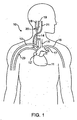
- Figure 1 is a schematic illustration of the upper torso of a human body showing the major arteries and veins and associated anatomy.
- Figure 2A is a cross-sectional schematic illustration of the carotid sinus and baroreceptors within the vascular wall.
- Figure 2B is a schematic illustration of baroreceptors within the vascular wall and the baroreflex system.
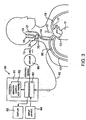
- Figure 3 is a schematic illustration of a baroreceptor activation system.
- Figures 4A and 4B are schematic illustrations of a baroreceptor activation device in the form of an implantable extraluminal conductive structure which electrically induces a baroreceptor signal.
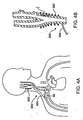
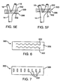
- FIGS 5A-5F are schematic illustrations of various possible arrangements of electrodes around the carotid sinus for extravascular electrical activation embodiments.
- Figure 6 is a schematic illustration of a serpentine shaped electrode for extravascular electrical activation embodiments.
- Figure 7 is a schematic illustration of a plurality of electrodes aligned orthogonal to the direction of wrapping around the carotid sinus for extravascular electrical activation embodiments.
- FIGS 8 - 11 are schematic illustrations of various multi-channel electrodes for extravascular electrical activation embodiments.
- Figure 12 is a schematic illustration of an extravascular electrical activation device including a tether and an anchor disposed about the carotid sinus and common carotid artery.
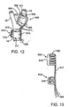
- Figure 13 is a schematic illustration of an alternative extravascular electrical activation device including a plurality of ribs and a spine.
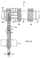
- Figure 14 is a schematic illustration of an electrode assembly for extravascular electrical activation embodiments.
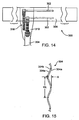
- Figure 15 is a schematic illustration of a fragment of an alternative cable for use with an electrode assembly such as shown in Figure 14 .
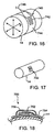
- Figure 16 illustrates a foil strain gauge for measuring expansion force of a carotid artery or other blood vessel.
- Figure 17 illustrates a transducer which is adhesively connected to the wall of an artery.
- Figure 18 is a cross-sectional view of the transducer of Figure 17 .
- Figure 19 illustrates a first exemplary electrode assembly having an elastic base and plurality of attachment tabs.
- Figure 20 is a more detailed illustration of the electrode-carrying surface of the electrode assembly of Figure 19 .
- Figure 21 is a detailed illustration of electrode coils which are present in an elongate lead of the electrode assembly of Figure 19 .
- Figure 22 is a detailed view of the electrode-carrying surface of an electrode assembly similar to that shown in Figure 20 , except that the electrodes have been flattened.
- Figure 23 is a cross-sectional view of the electrode structure of Figure 22 .
- Figure 24 illustrates the transition between the flattened and non-flattened regions of the electrode coil of the electrode assembly Figure 20 .
- Figure 25 is a cross-sectional view taken along the line 25-25 of Figure 24 .
- Figure 26 is a cross-sectional view taken along the line 26-26 of Figure 24 .
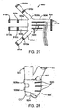
- Figure 27 is an illustration of a further exemplary electrode assembly.
- Figure 28 illustrates the electrode assembly of Figure 27 wrapped around the common carotid artery near the carotid bifurcation.
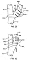
- Figure 29 illustrates the electrode assembly of Figure 27 wrapped around the internal carotid artery.
- Figure 30 is similar to Figure 29 , but with the carotid bifurcation having a different geometry.
- FIG. 1 is a schematic illustration of the upper torso of a human body 10 showing some of the major arteries and veins of the cardiovascular system.
- the left ventricle of the heart 11 pumps oxygenated blood up into the aortic arch 12.
- the right subclavian artery 13, the right common carotid artery 14, the left common carotid artery 15 and the left subclavian artery 16 branch off the aortic arch 12 proximal of the descending thoracic aorta 17.
- brachiocephalic artery 22 connects the right subclavian artery 13 and the right common carotid artery 14 to the aortic arch 12.
- the right carotid artery 14 bifurcates into the right external carotid artery 18 and the right internal carotid artery 19 at the right carotid sinus 20.
- the left carotid artery 15 similarly bifurcates into the left external carotid artery and the left internal carotid artery at the left carotid sinus.
- oxygenated blood flows into the carotid arteries 18/19 and the subclavian arteries 13/16.
- oxygenated blood circulates through the head and cerebral vasculature and oxygen depleted blood returns to the heart 11 by way of the jugular veins, of which only the right internal jugular vein 21 is shown for sake of clarity.
- oxygenated blood circulates through the upper peripheral vasculature and oxygen depleted blood returns to the heart by way of the subclavian veins, of which only the right subclavian vein 23 is shown, also for sake of clarity.
- the heart 11 pumps the oxygen depleted blood through the pulmonary system where it is re-oxygenated.
- the re-oxygenated blood returns to the heart 11 which pumps the re-oxygenated blood into the aortic arch as described above, and the cycle repeats.
- baroreceptors 30 Within the arterial walls of the aortic arch 12, common carotid arteries 14/15 (near the right carotid sinus 20 and left carotid sinus), subclavian arteries 13/16 and brachiocephalic artery 22 there are baroreceptors 30.
- baroreceptors 30 reside within the vascular walls of the carotid sinus 20.
- Baroreceptors 30 are a type of stretch receptor used by the body to sense blood pressure. An increase in blood pressure causes the arterial wall to stretch, and a decrease in blood pressure causes the arterial wall to return to its original size. Such a cycle is repeated with each beat of the heart.
- baroreceptors 30 are located within the arterial wall, they are able to sense deformation of the adjacent tissue, which is indicative of a change in blood pressure.
- the baroreceptors 30 located in the right carotid sinus 20, the left carotid sinus and the aortic arch 12 play the most significant role in sensing blood pressure that affects the baroreflex system 50, which is described in more detail with reference to Figure 2B .
- FIG. 2B shows a schematic illustration of baroreceptors 30 disposed in a generic vascular wall 40 and a schematic flow chart of the baroreflex system 50.
- Baroreceptors 30 are profusely distributed within the arterial walls 40 of the major arteries discussed previously, and generally form an arbor 32.
- the baroreceptor arbor 32 comprises a plurality of baroreceptors 30, each of which transmits baroreceptor signals to the brain 52 via nerve 38.
- the baroreceptors 30 are so profusely distributed and arborized within the vascular wall 40 that discrete baroreceptor arbours 32 are not readily discernable.
- the baroreceptors 30 shown in Figure 2B are primarily schematic for purposes of illustration and discussion.
- Baroreceptor signals are used to activate a number of body systems which collectively may be referred to as the baroreflex system 50.
- Baroreceptors 30 are connected to the brain 52 via the nervous system 51.
- the brain 52 is able to detect changes in blood pressure, which is indicative of cardiac output. If cardiac output is insufficient to meet demand (i.e., the heart 11 is unable to pump sufficient blood), the baroreflex system 50 activates a number of body systems, including the heart 11, kidneys 53, vessels 54, and other organs/tissues. Such activation of the baroreflex system 50 generally corresponds to an increase in neurohormonal activity.
- the baroreflex system 50 initiates a neurohormonal sequence that signals the heart 11 to increase heart rate and increase contraction force in order to increase cardiac output, signals the kidneys 53 to increase blood volume by retaining sodium and water, and signals the vessels 54 to constrict to elevate blood pressure.
- the cardiac, renal and vascular responses increase blood pressure and cardiac output 55, and thus increase the workload of the heart 11. In a patient with heart failure, this further accelerates myocardial damage and exacerbates the heart failure state.
- the baroreflex system 50 is activated to reduce excessive blood pressure, autonomic nervous system activity and neurohormonal activation.
- the present invention provides a number of devices by which baroreceptors 30 may be activated, thereby indicating an increase in blood pressure and signaling the brain 52 to reduce the body's blood pressure and level of sympathetic nervous system and neurohormonal activation, and increase parasypathetic nervous system activation, thus having a beneficial effect on the cardiovascular system and other body systems.
- a system including a control system 60, a baroreceptor activation device 70, and a sensor 80 (optional), which generally operate in the following manner.
- the sensor(s) 80 optionally senses and/or monitors a parameter (e.g., cardiovascular function) indicative of the need to modify the baroreflex system and generates a signal indicative of the parameter.
- the control system 60 generates a control signal as a function of the received sensor signal.
- the control signal activates, deactivates or otherwise modulates the baroreceptor activation device 70.
- activation of the device 70 results in activation of the baroreceptors 30.
- deactivation or modulation of the baroreceptor activation device 70 may cause or modify activation of the baroreceptors 30.
- the baroreceptor activation device 70 may comprise a wide variety of devices which utilize electrical means to activate baroreceptors 30.
- the control system 60 when the sensor 80 detects a parameter indicative of the need to modify the baroreflex system activity (e.g., excessive blood pressure), the control system 60 generates a control signal to modulate (e.g. activate) the baroreceptor activation device 70 thereby inducing a baroreceptor 30 signal that is perceived by the brain 52 to be apparent excessive blood pressure.
- the control system 60 When the sensor 80 detects a parameter indicative of normal body function (e.g., normal blood pressure), the control system 60 generates a control signal to modulate (e.g., deactivate) the baroreceptor activation device 70.
- the baroreceptor activation device 70 may comprise a wide variety of devices which utilize electrical means to activate the baroreceptors 30.
- the baroreceptor activation device 70 described herein comprises an electrode structure which directly activates one or more baroreceptors 30 by changing the electrical potential across the baroreceptors 30. It is possible that changing the electrical potential across the tissue surrounding the baroreceptors 30 may cause the surrounding tissue to stretch or otherwise deform, thus mechanically activating the baroreceptors 30, in which case the stretchable and elastic electrode structures described herein may provide significant advantages.
- the baroreceptor activation device 70 may be positioned anywhere baroreceptors 30 are present. Such potential implantation sites are numerous, such as the aortic arch 12, in the common carotid arteries 18/19 near the carotid sinus 20, in the subclavian arteries 13/16, in the brachiocephalic artery 22, or in other arterial or venous locations.
- the electrode structures described herein will be implanted such that they are positioned on or over a vascular structure immediately adjacent the baroreceptors 30.
- the electrode structure of the baroreceptor activation device 70 is implanted near the right carotid sinus 20 and/or the left carotid sinus (near the bifurcation of the common carotid artery) and/or the aortic arch 12, where baroreceptors 30 have a significant impact on the baroreflex system 50.
- the electrode structure of the baroreceptor activation device 70 is implanted near the right carotid sinus 20 and/or the left carotid sinus (near the bifurcation of the common carotid artery) and/or the aortic arch 12, where baroreceptors 30 have a significant impact on the baroreflex system 50.
- embodiments are described with reference to baroreceptor activation device 70 positioned near the carotid sinus 20.
- the optional sensor 80 is operably coupled to the control system 60 by electric sensor cable or lead 82.
- the sensor 80 may comprise any suitable device that measures or monitors a parameter indicative of the need to modify the activity of the baroreflex system.
- the sensor 80 may comprise a physiologic transducer or gauge that measures ECG, blood pressure (systolic, diastolic, average or pulse pressure), blood volumetric flow rate, blood flow velocity, blood pH, 02 or CO2 content, mixed venous oxygen saturation (SVO2), vasoactivity, nerve activity, tissue activity, body movement, activity levels, respiration, or composition.
- suitable transducers or gauges for the sensor 80 include ECG electrodes, a piezoelectric pressure transducer, an ultrasonic flow velocity transducer, an ultrasonic volumetric flow rate transducer, a thermodilution flow velocity transducer, a capacitive pressure transducer, a membrane pH electrode, an optical detector (SVO2), tissue impedance (electrical), or a strain gauge. Although only one sensor 80 is shown, multiple sensors 80 of the same or different type at the same or different locations may be utilized.
- An example of an implantable blood pressure measurement device that may be disposed about a blood vessel is disclosed in U.S. Patent No. 6,106,477 to Miesel et al.
- An example of a subcutaneous ECG monitor is available from Medtronic under the trade name REVEAL ILR and is disclosed in PCT Publication No. WO 98/02209 .
- Other examples are disclosed in U.S. Patent Nos. 5,987,352 and 5,331,966 .
- Examples of devices and methods for measuring absolute blood pressure utilizing an ambient pressure reference are disclosed in U.S. Patent No. 5,810,735 to Halperin et al. , U.S. Patent No. 5,904,708 to Goedeke , and PCT Publication No. WO 00/16686 to Brockway et al.
- the sensor 80 described herein may take the form of any of these devices or other devices that generally serve the same purpose.
- the sensor 80 is preferably positioned in a chamber of the heart 11, or in/on a major artery such as the aortic arch 12, a common carotid artery 14/15, a subclavian artery 13/16 or the brachiocephalic artery 22, such that the parameter of interest may be readily ascertained.
- the sensor 80 may be disposed inside the body such as in or on an artery, a vein or a nerve (e.g. vagus nerve), or disposed outside the body, depending on the type of transducer or gauge utilized.
- the sensor 80 may be separate from the baroreceptor activation device 70 or combined therewith. For purposes of illustration only, the sensor 80 is shown positioned on the right subclavian artery 13.
- control system 60 includes a control block 61 comprising a processor 63 and a memory 62.
- Control system 60 is connected to the sensor 80 by way of sensor cable 82.
- Control system 60 is also connected to the baroreceptor activation device 70 by way of electric control cable 72.
- the control system 60 receives a sensor signal from the sensor 80 by way of sensor cable 82, and transmits a control signal to the baroreceptor activation device 70 by way of control cable 72.
- the system components 60/70/80 may be directly linked via cables 72/82 or by indirect means such as RF signal transceivers, ultrasonic transceivers or galvanic couplings. Examples of such indirect interconnection devices are disclosed in U.S. Patent No. 4,987,897 to Funke and U.S. Patent No. 5,113,859 to Funke .
- the memory 62 may contain data related to the sensor signal, the control signal, and/or values and commands provided by the input device 64.
- the memory 62 may also include software containing one or more algorithms defining one or more functions or relationships between the control signal and the sensor signal.
- the algorithm may dictate activation or deactivation control signals depending on the sensor signal or a mathematical derivative thereof.
- the algorithm may dictate an activation or deactivation control signal when the sensor signal falls below a lower predetermined threshold value, rises above an upper predetermined threshold value or when the sensor signal indicates a specific physiologic event.
- the algorithm may dynamically alter the threshold value as determined by the sensor input values.
- the baroreceptor activation device 70 activates baroreceptors 30 electrically, optionally in combination with mechanical, thermal, chemical, biological or other co-activation.
- the control system 60 includes a driver 66 to provide the desired power mode for the baroreceptor activation device 70.
- the driver 66 may comprise a power amplifier or the like and the cable 72 may comprise electrical lead(s).
- the driver 66 may not be necessary, particularly if the processor 63 generates a sufficiently strong electrical signal for low level electrical actuation of the baroreceptor activation device 70.
- the control system 60 may operate as a closed loop utilizing feedback from the sensor 80, or other sensors, such as heart rate sensors which may be incorporated or the electrode assembly, or as an open loop utilizing reprogramming commands received by input device 64.
- the closed loop operation of the control system 60 preferably utilizes some feedback from the transducer 80, but may also operate in an open loop mode without feedback.
- Programming commands received by the input device 64 may directly influence the control signal, the output activation parameters, or may alter the software and related algorithms contained in memory 62.
- the treating physician and/or patient may provide commands to input device 64.
- Display 65 may be used to view the sensor signal, control signal and/or the software/data contained in memory 62.
- the control signal generated by the control system 60 may be continuous, periodic, alternating, episodic or a combination thereof, as dictated by an algorithm contained in memory 62.
- Continuous control signals include a constant pulse, a constant train of pulses, a triggered pulse and a triggered train of pulses.
- periodic control signals include each of the continuous control signals described above which have a designated start time (e.g., beginning of each period as designated by minutes, hours, or days in combinations of) and a designated duration (e.g., seconds, minutes, hours, or days in combinations of).
- Examples of alternating control signals include each of the continuous control signals as described above which alternate between the right and left output channels.
- Examples of episodic control signals include each of the continuous control signals described above which are triggered by an episode (e.g., activation by the physician/patient, an increase/decrease in blood pressure above a certain threshold, heart rate above/below certain levels, etc.).
- the stimulus regimen governed by the control system 60 may be selected to promote long term efficacy. It is theorized that uninterrupted or otherwise unchanging activation of the baroreceptors 30 may result in the baroreceptors and/or the baroreflex system becoming less responsive over time, thereby diminishing the long term effectiveness of the therapy. Therefore, the stimulus regimen maybe selected to activate, deactivate or otherwise modulate the baroreceptor activation device 70 in such a way that therapeutic efficacy is maintained preferably for years.
- the stimulus regimens described herein may be selected reduce power requirement/consumption of the system 60.
- the stimulus regimen may dictate that the baroreceptor activation device 70 be initially activated at a relatively higher energy and/or power level, and subsequently activated at a relatively lower energy and/or power level.
- the first level attains the desired initial therapeutic effect
- the second (lower) level sustains the desired therapeutic effect long term.
- the energy required or consumed by the activation device 70 is also reduced long term. This may correlate into systems having greater longevity and/or reduced size (due to reductions in the size of the power supply and associated components).
- a first general approach for a stimulus regimen which promotes long term efficacy and reduces power requirements/consumption involves generating a control signal to cause the baroreceptor activation device 70 to have a first output level of relatively higher energy and/or power, and subsequently changing the control signal to cause the baroreceptor activation device 70 to have a second output level of relatively lower energy and/or power.
- the first output level may be selected and maintained for sufficient time to attain the desired initial effect (e.g., reduced heart rate and/or blood pressure), after which the output level may be reduced to the second level for sufficient time to sustain the desired effect for the desired period of time.
- the second output level may have a power and/or energy value of X2, wherein X2 is less than X1.
- X2 may be equal to zero, such that the first level is "on" and the second level is "off.
- power and energy refer to two different parameters, and in some cases, a change in one of the parameters (power or energy) may not correlate to the same or similar change in the other parameter. In the described embodiments, it is contemplated that a change in one or both of the parameters may be suitable to obtain the desired result of promoting long term efficacy.
- each further level may increase the output energy or power to attain the desired effect, or decrease the output energy or power to retain the desired effect. For example, in some instances, it may be desirable to have further reductions in the output level if the desired effect may be sustained at lower power or energy levels. In other instances, particularly when the desired effect is diminishing or is otherwise not sustained, it may be desirable to increase the output level until the desired effect is reestablished, and subsequently decrease the output level to sustain the effect.
- the transition from each level may be a step function (e.g., a single step or a series of steps), a gradual transition over a period of time, or a combination thereof.
- the signal levels may be continuous, periodic, alternating, or episodic as discussed previously.
- the output (power or energy) level of the baroreceptor activation device 70 may be changed by adjusting the output signal voltage level, current level and/or signal duration.
- the output signal of the baroreceptor activation device 70 may be, for example, constant current or constant voltage.
- several pulse characteristics may be changed individually or in combination to change the power or energy level of the output signal.
- Such pulse characteristics include, but are not limited to: pulse amplitude (PA), pulse frequency (PF), pulse width or duration (PW), pulse waveform (square, triangular, sinusoidal, etc.), pulse polarity (for bipolar electrodes) and pulse phase (monophasic, biphasic).
- FIGS 4A and 4B show schematic illustrations of a baroreceptor activation device 300 in the form of an extravascular electrically conducive structure or electrode 302.
- the electrode structure 302 may comprise a coil, braid or other structure capable of surrounding the vascular wall.
- the electrode structure 302 may comprise one or more electrode patches distributed around the outside surface of the vascular wall. Because the electrode structure 302 is disposed on the outside surface of the vascular wall, intravascular delivery techniques may not be practical, but minimally invasive surgical techniques will suffice.
- the extravascular electrode structure 302 may receive electrical signals directly from the driver 66 of the control system 60 by way of electrical lead 304, or indirectly by utilizing an inductor (not shown) as described in copending commonly assigned application no. 10/ (Attorney Docket No. 21433-000420), filed on the same day as the present application.
- FIGS 5A - 5F show schematic illustrations of various possible arrangements of electrodes around the carotid sinus 20 for extravascular electrical activation embodiments, such as baroreceptor activation device 300 described with reference to Figures 4A and 4B .
- the electrode designs illustrated and described hereinafter may be particularly suitable for connection to the carotid arteries at or near the carotid sinus, and may be designed to minimize extraneous tissue stimulation.
- the carotid arteries are shown, including the common 14, the external 18 and the internal 19 carotid arteries.
- the location of the carotid sinus 20 may be identified by a landmark bulge 21, which is typically located on the internal carotid artery 19 just distal of the bifurcation, or extends across the bifurcation from the common carotid artery 14 to the internal carotid artery 19.
- the carotid sinus 20, and in particular the bulge 21 of the carotid sinus may contain a relatively high density of baroreceptors 30 (not shown) in the vascular wall. For this reason, it may be desirable to position the electrodes 302 of the activation device 300 on and/or around the sinus bulge 21 to maximize baroreceptor responsiveness and to minimize extraneous tissue stimulation.
- the device 300 and electrodes 302 are merely schematic, and only a portion of which may be shown, for purposes of illustrating various positions of the electrodes 302 on and/or around the carotid sinus 20 and the sinus bulge 21.
- the electrodes 302 may be monopolar, bipolar, or tripolar (anode-cathode-anode or cathode-anode-cathode sets). Specific extravascular electrode designs are described in more detail hereinafter.
- the electrodes 302 of the extravascular electrical activation device 300 extend around a portion or the entire circumference of the sinus 20 in a circular fashion. Often, it would be desirable to reverse the illustrated electrode configuration in actual use.
- the electrodes 302 of the extravascular electrical activation device 300 extend around a portion or the entire circumference of the sinus 20 in a helical fashion. In the helical arrangement shown in Figure 5B , the electrodes 302 may wrap around the sinus 20 any number of times to establish the desired electrode 302 contact and coverage. In the circular arrangement shown in Figure 5A , a single pair of electrodes 302 may wrap around the sinus 20, or a plurality of electrode pairs 302 may be wrapped around the sinus 20 as shown in Figure 5C to establish more electrode 302 contact and coverage.
- the plurality of electrode pairs 302 may extend from a point proximal of the sinus 20 or bulge 21, to a point distal of the sinus 20 or bulge 21 to ensure activation of baroreceptors 30 throughout the sinus 20 region.
- the electrodes 302 may be connected to a single channel or multiple channels as discussed in more detail hereinafter.
- the plurality of electrode pairs 302 may be selectively activated for purposes of targeting a specific area of the sinus 20 to increase baroreceptor responsiveness, or for purposes of reducing the exposure of tissue areas to activation to maintain baroreceptor responsiveness long term.
- the electrodes 302 extend around the entire circumference of the sinus 20 in a criss cross fashion.
- the criss cross arrangement of the electrodes 302 establishes contact with both the internal 19 and external 18 carotid arteries around the carotid sinus 20.
- the electrodes 302 extend around all or a portion of the circumference of the sinus 20, including the internal 19 and external 18 carotid arteries at the bifurcation, and in some instances the common carotid artery 14.
- the electrodes 302 extend around all or a portion of the circumference of the sinus 20, including the internal 19 and external 18 carotid arteries distal of the bifurcation.
- the extravascular electrical activation devices 300 are shown to include a substrate or base structure 306 which may encapsulate and insulate the electrodes 302 and may provide a means for attachment to the sinus 20 as described in more detail hereinafter.
- the electrodes 302 of the activation device 300 there are a number of suitable arrangements for the electrodes 302 of the activation device 300, relative to the carotid sinus 20 and associated anatomy.
- the electrodes 302 are wrapped around a portion of the carotid structure, which may require deformation of the electrodes 302 from their relaxed geometry (e.g., straight).
- the electrodes 302 and/or the base structure 306 may have a relaxed geometry that substantially conforms to the shape of the carotid anatomy at the point of attachment.
- the electrodes 302 and the base structure or backing 306 may be pre shaped to conform to the carotid anatomy in a substantially relaxed state.
- the electrodes 302 may have a geometry and/or orientation that reduces the amount of electrode 302 strain.
- the backing or base structure 306 may be elastic or stretchable to facilitate wrapping of and conforming to the carotid sinus or other vascular structure.
- the electrodes 302 are shown to have a serpentine or wavy shape.
- the serpentine shape of the electrodes 302 reduces the amount of strain seen by the electrode material when wrapped around a carotid structure.
- the serpentine shape of the electrodes increases the contact surface area of the electrode 302 with the carotid tissue.
- the electrodes 302 may be arranged to be substantially orthogonal to the wrap direction (i.e., substantially parallel to the axis of the carotid arteries) as shown in Figure 7 .
- the electrodes 302 each have a length and a width or diameter, wherein the length is substantially greater than the width or diameter.
- the electrodes 302 each have a longitudinal axis parallel to the length thereof, wherein the longitudinal axis is orthogonal to the wrap direction and substantially parallel to the longitudinal axis of the carotid artery about which the device 300 is wrapped. As with the multiple electrode embodiments described previously, the electrodes 302 may be connected to a single channel or multiple channels as discussed in more detail hereinafter.
- Figure 8 illustrates a six (6) channel electrode assembly including six (6) separate elongate electrodes 302 extending adjacent to and parallel with each other.
- the electrodes 302 are each connected to multi-channel cable 304. Some of the electrodes 302 may be common, thereby reducing the number of conductors necessary in the cable 304.
- Base structure or substrate 306 may comprise a flexible and electrically insulating material suitable for implantation, such as silicone, perhaps reinforced with a flexible material such as polyester fabric.
- the base 306 may have a length suitable to wrap around all (360°) or a portion (i.e., less than 360°) of the circumference of one or more of the carotid arteries adjacent the carotid sinus 20.
- the electrodes 302 may extend around a portion (i.e., less than 360° such as 270°, 180° or 90°) of the circumference of one or more of the carotid arteries adjacent the carotid sinus 20.
- the electrodes 302 may have a length that is less than (e.g., 75%, 50% or 25%) the length of the base 206.
- the electrodes 302 may be parallel, orthogonal or oblique to the length of the base 306, which is generally orthogonal to the axis of the carotid artery to which it is disposed about.
- the base structure or backing will be elastic (i.e., stretchable), typically being composed of at least in part of silicone, latex, or other elastomer. If such elastic structures are reinforced, the reinforcement should be arranged so that it does not interfere with the ability of the base to stretch and conform to the vascular surface.
- the electrodes 302 may comprise round wire, rectangular ribbon or foil formed of an electrically conductive and radiopaque material such as platinum.
- the base structure 306 substantially encapsulates the electrodes 302, leaving only an exposed area for electrical connection to extravascular carotid sinus tissue.
- each electrode 302 may be partially recessed in the base 206 and may have one side exposed along all or a portion of its length for electrical connection to carotid tissue. Electrical paths through the carotid tissues may be defined by one or more pairs of the elongate electrodes 302.
- the multi-channel electrodes 302 may be selectively activated for purposes of mapping and targeting a specific area of the carotid sinus 20 to determine the best combination of electrodes 302 (e.g., individual pair, or groups of pairs) to activate for maximum baroreceptor responsiveness, as described elsewhere herein.
- the multi-channel electrodes 302 may be selectively activated for purposes of reducing the exposure of tissue areas to activation to maintain long term efficacy as described , as described elsewhere herein. For these purposes, it may be useful to utilize more than two (2) electrode channels.
- the electrodes 302 may be connected to a single channel whereby baroreceptors are uniformly activated throughout the sinus 20 region.
- the device 300 includes sixteen (16) individual electrode pads 302 connected to 16 channel cable 304 via 4 channel connectors 303.
- the circular electrode pads 302 are partially encapsulated by the base structure 306 to leave one face of each button electrode 302 exposed for electrical connection to carotid tissues.
- electrical paths through the carotid tissues may be defined by one or more pairs (bipolar) or groups (tripolar) of electrode pads 302.
- the device 300 includes sixteen (16) individual circular pad electrodes 302 surrounded by sixteen (16) rings 305, which collectively may be referred to as concentric electrode pads 302/305.
- Pad electrodes 302 are connected to 17 channel cable 304 via 4 channel connectors 303, and rings 305 are commonly connected to 17 channel cable 304 via a single channel connector 307.
- the circular shaped electrodes 302 and the rings 305 are partially encapsulated by the base structure 306 to leave one face of each pad electrode 302 and one side of each ring 305 exposed for electrical connection to carotid tissues.
- two rings 305 may surround each electrode 302, with the rings 305 being commonly connected. With these arrangements, electrical paths through the carotid tissues may be defined between one or more pad electrode 302 / ring 305 sets to create localized electrical paths.
- the device 300 includes a control IC chip 310 connected to 3 channel cable 304.
- the control chip 310 is also connected to sixteen (16) individual pad electrodes 302 via 4 channel connectors 303.
- the control chip 310 permits the number of channels in cable 304 to be reduced by utilizing a coding system.
- the control system 60 sends a coded control signal which is received by chip 310.
- the chip 310 converts the code and enables or disables selected electrode 302 pairs in accordance with the code.
- control signal may comprise a pulse wave form, wherein each pulse includes a different code.
- the code for each pulse causes the chip 310 to enable one or more pairs of electrodes, and to disable the remaining electrodes.
- the pulse is only transmitted to the enabled electrode pair(s) corresponding to the code sent with that pulse.
- Each subsequent pulse would have a different code than the preceding pulse, such that the chip 310 enables and disables a different set of electrodes 302 corresponding to the different code.
- the IC chip 310 may be connected to feedback sensor 80, taking advantage of the same functions as described with reference to Figure 3 .
- one or more of the electrodes 302 may be used as feedback sensors when not enabled for activation.
- a feedback sensor electrode may be used to measure or monitor electrical conduction in the vascular wall to provide data analogous to an ECG.
- such a feedback sensor electrode may be used to sense a change in impedance due to changes in blood volume during a pulse pressure to provide data indicative of heart rate, blood pressure, or other physiologic parameter.
- FIG 12 schematically illustrates an extravascular electrical activation device 300 including a support collar or anchor 312.
- the activation device 300 is wrapped around the internal carotid artery 19 at the carotid sinus 20, and the support collar 312 is wrapped around the common carotid artery 14.
- the activation device 300 is connected to the support collar 312 by cables 304, which act as a loose tether.
- the collar 312 isolates the activation device from movements and forces transmitted by the cables 304 proximal of the support collar, such as may be encountered by movement of the control system 60 and/or driver 66.
- a strain relief (not shown) may be connected to the base structure 306 of the activation device 300 at the juncture between the cables 304 and the base 306. With either approach, the position of the device 300 relative to the carotid anatomy may be better maintained despite movements of other parts of the system.
- the base structure 306 of the activation device 300 may comprise molded tube, a tubular extrusion, or a sheet of material wrapped into a tube shape utilizing a suture flap 308 with sutures 309 as shown.
- the base structure 306 may be formed of a flexible and biocompatible material such as silicone, which may be reinforced with a flexible material such as polyester fabric available under the trade name DACRON ® to form a composite structure.
- the inside diameter of the base structure 306 may correspond to the outside diameter of the carotid artery at the location of implantation, for example 6 to 8 mm.
- the wall thickness of the base structure 306 may be very thin to maintain flexibility and a low profile, for example less than 1 mm. If the device 300 is to be disposed about a sinus bulge 21, a correspondingly shaped bulge may be formed into the base structure for added support and assistance in positioning.
- the electrodes 302 may comprise round wire, rectangular ribbon or foil, formed of an electrically conductive and radiopaque material such as platinum or platinum iridium.
- the electrodes may be molded into the base structure 306 or adhesively connected to the inside diameter thereof, leaving a portion of the electrode exposed for electrical connection to carotid tissues.
- the electrodes 302 may encompass less than the entire inside circumference (e.g., 300°) of the base structure 306 to avoid shorting.
- the electrodes 302 may have any of the shapes and arrangements described previously. For example, as shown in Figure 12 , two rectangular ribbon electrodes 302 may be used, each having a width of 1 mm spaced 1.5 mm apart.
- the support collar 312 may be formed similarly to base structure 306.
- the support collar may comprise molded tube, a tubular extrusion, or a sheet of material wrapped into a tube shape utilizing a suture flap 315 with sutures 313 as shown.
- the support collar 312 may be formed of a flexible and biocompatible material such as silicone, which may be reinforced to form a composite structure.
- the cables 304 are secured to the support collar 312, leaving slack in the cables 304 between the support collar 312 and the activation device 300.
- sutures 311 may be used to maintain the position of the electrical activation device 300 relative to the carotid anatomy (or other vascular site containing baroreceptors).
- Such sutures 311 may be connected to base structure 306, and pass through all or a portion of the vascular wall.
- the sutures 311 maybe threaded through the base structure 306, through the adventitia of the vascular wall, and tied. If the base structure 306 comprises a patch or otherwise partially surrounds the carotid anatomy, the corners and/or ends of the base structure may be sutured, with additional sutures evenly distributed therebetween.
- a reinforcement material such as polyester fabric may be embedded in the silicone material.
- other fixation means may be employed such as staples or a biocompatible adhesive, for example.
- FIG. 13 schematically illustrates an alternative extravascular electrical activation device 300 including one or more electrode ribs 316 interconnected by spine 317.
- a support collar 312 having one or more (non electrode) ribs 316 may be used to isolate the activation device 300 from movements and forces transmitted by the cables 304 proximal of the support collar 312.
- the ribs 316 of the activation device 300 are sized to fit about the carotid anatomy, such as the internal carotid artery 19 adjacent the carotid sinus 20.
- the ribs 316 of the support collar 312 may be sized to fit about the carotid anatomy, such as the common carotid artery 14 proximal of the carotid sinus 20.
- the ribs 316 may be separated, placed on a carotid artery, and closed thereabout to secure the device 300 to the carotid anatomy.
- Each of the ribs 316 of the device 300 includes an electrode 302 on the inside surface thereof for electrical connection to carotid tissues.
- the ribs 316 provide insulating material around the electrodes 302, leaving only an inside portion exposed to the vascular wall.
- the electrodes 302 are coupled to the multi-channel cable 304 through spine 317.
- Spine 317 also acts as a tether to ribs 316 of the support collar 312, which do not include electrodes since their function is to provide support.
- the multi-channel electrode 302 functions discussed with reference to Figures 8 - 11 are equally applicable to this embodiment.
- the ends of the ribs 316 may be connected (e.g., sutured) after being disposed about a carotid artery, or may remain open as shown. If the ends remain open, the ribs 316 may be formed of a relatively stiff material to ensure a mechanical lock around the carotid artery.
- the ribs 316 may be formed of polyethylene, polypropylene, PTFE, or other similar insulating and biocompatible material.
- the ribs 316 may be formed of a metal such as stainless steel or a nickel titanium alloy, as long as the metallic material was electrically isolated from the electrodes 302.
- the ribs 316 may comprise an insulating and biocompatible polymeric material with the structural integrity provided by metallic (e.g., stainless steel, nickel titanium alloy, etc.) reinforcement.
- metallic e.g., stainless steel, nickel titanium alloy, etc.
- the electrodes 302 may comprise the metallic reinforcement.
- the base structure 306 comprises a silicone sheet having a length of 5.0 inches, a thickness of 0.007 inches, and a width of 0.312 inches.
- the electrodes 302 comprise platinum ribbon having a length of 0.47 inches, a thickness of 0.0005 inches, and a width of 0.040 inches.
- the electrodes 302 are adhesively connected to one side of the silicone sheet 306.
- the electrodes 302 are connected to a modified bipolar endocardial pacing lead, available under the trade name CONIFIX from Innomedica (now BIOMEC Cardiovascular, Inc.), model number 501112.
- the proximal end of the cable 304 is connected to the control system 60 or driver 66 as described previously.
- the pacing lead is modified by removing the pacing electrode to form the cable body 304'.
- the MP35 wires are extracted from the distal end thereof to form two coils 318 positioned side by side having a diameter of about 0.020 inches.
- the coils 318 are then attached to the electrodes utilizing 316 type stainless steel crimp terminals laser welded to one end of the platinum electrodes 302.
- the distal end of the cable 304 and the connection between the coils 318 and the ends of the electrodes 302 are encapsulated by silicone.
- the cable 304 illustrated in Figure 14 comprises a coaxial type cable including two coaxially disposed coil leads separated into two separate coils 318 for attachment to the electrodes 302.
- An alternative cable 304 construction is illustrated in Figure 15.
- Figure 15 illustrates an alternative cable body 304 which may be formed in a curvilinear shape such as a sinusoidal configuration, prior to implantation.
- the curvilinear configuration readily accommodates a change in distance between the device 300 and the control system 60 or the driver 66. Such a change in distance may be encountered during flexion and/or extension of the neck of the patient after implantation.
- the cable body 304 may comprise two or more conductive wires 304a arranged coaxially or collinearly as shown.
- Each conductive wire 304a may comprise a multifilament structure of suitable conductive material such as stainless steel or MP35N.
- An insulating material may surround the wire conductors 304a individually and/or collectively.
- a pair of electrically conductive wires 304a having an insulating material surrounding each wire 304a individually is shown.
- the insulated wires 304a may be connected by a spacer 304b comprising, for example, an insulating material.
- An additional jacket of suitable insulating material may surround each of the conductors 304a.
- the insulating jacket may be formed to have the same curvilinear shape of the insulated wires 304a to help maintain the shape of the cable body 304 during implantation.
- the amplitude (A) may range from 1 mm to 10 mm, and preferably ranges from 2 mm to 3 mm.
- the wavelength (WL) of the sinusoid may range from 2 mm to 20 mm, and preferably ranges from 4 mm to 10 mm.
- the curvilinear or sinusoidal shape may be formed by a heat setting procedure utilizing a fixture which holds the cable 304 in the desired shape while the cable is exposed to heat. Sufficient heat is used to heat set the conductive wires 304a and/or the surrounding insulating material. After cooling, the cable 304 may be removed from the fixture, and the cable 304 retains the desired shape.
- an implantable blood pressure measurement device that may be disposed about a blood vessel is disclosed in U.S. Patent No. 6,106,477 to Miesel et al. The output from such gauges may be correlated to blood pressure and/or heart rate, for example, and may be used to provide feedback to the control system 60 as described previously herein.
- an implantable pressure measuring assembly comprises a foil strain gauge or force sensing resistor device 740 disposed about an artery such as common carotid artery 14.
- a transducer portion 742 may be mounted to a silicone base or backing 744 which is wrapped around and sutured or otherwise attached to the artery 14.
- the transducer 750 may be adhesively connected to the wall of the artery 14 using a biologically compatible adhesive such as cyanoacrylate as shown in Figure 17 .
- the transducer 750 comprises a micro machined sensor (MEMS) that measures force or pressure.
- MEMS micro machined sensor
- the MEMS transducer 750 includes a micro arm 752 (shown in section in Figure 18 ) coupled to a silicon force sensor contained over an elastic base 754.
- a cap 756 covers the arm 752 a top portion of the base 754.
- the base 754 include an interior opening creating access from the vessel wall 14 to the arm 752.
- An incompressible gel 756 fills the space between the arm 752 and the vessel wall 14 such that force is transmitted to the arm upon expansion and contraction of the vessel wall.
- changes in blood pressure within the artery cause changes in vessel wall stress which are detected by the transducer and which may be correlated with the blood pressure.
- FIGS 19 - 21 illustrate an alternative extravascular electrical activation device 700, which, may also be referred to as an electrode cuff device or more generally as an "electrode assembly.” Except as described herein and shown in the drawings, device 700 may be the same in design and function as extravascular electrical activation device 300 described previously.
- electrode assembly or cuff device 700 includes coiled electrode conductors 702/704 embedded in a flexible support 706.
- an outer electrode coil 702 and an inner electrode coil 704 are used to provide a pseudo tripolar arrangement, but other polar arrangements are applicable as well as described previously.
- the coiled electrodes 702/704 may be formed of fine round, flat or ellipsoidal wire such as 0.002 inch diameter round PtIr alloy wire wound into a coil form having a nominal diameter of 0.015 inches with a pitch of 0.004 inches, for example.
- the flexible support or base 706 may be formed of a biocompatible and flexible (preferably elastic) material such as silicone or other suitable thin walled elastomeric material having a wall thickness of 0.005 inches and a length (e.g., 2.95 inches) sufficient to surround the carotid sinus, for example.
- a biocompatible and flexible (preferably elastic) material such as silicone or other suitable thin walled elastomeric material having a wall thickness of 0.005 inches and a length (e.g., 2.95 inches) sufficient to surround the carotid sinus, for example.
- Each turn of the coil in the contact area of the electrodes 702/704 is exposed from the flexible support 706 and any adhesive to form a conductive path to the artery wall.
- the exposed electrodes 702/704 may have a length (e.g., 0.236 inches) sufficient to extend around at least a portion of the carotid sinus, for example.
- the electrode cuff 700 is assembled flat with the contact surfaces of the coil electrodes 702/704 tangent to the inside plane of the flexible support 706. When the electrode cuff 700 is wrapped around the artery, the inside contact surfaces of the coiled electrodes 702/704 are naturally forced to extend slightly above the adjacent surface of the flexible support, thereby improving contact to the artery wall.
- the ratio of the diameter of the coiled electrodes 702/704 to the wire diameter is preferably large enough to allow the coil to bend and elongate without significant bending stress or torsional stress in the wire. Flexibility is a significant advantage of this design which allows the electrode cuff 700 to conform to the shape of the carotid artery and sinus, and permits expansion and contraction of the artery or sinus without encountering significant stress or fatigue.
- the flexible electrode cuff 700 may be wrapped around and stretched to conform to the shape of the carotid sinus and artery during implantation. This may be achieved without collapsing or distorting the shape of the artery and carotid sinus due to the compliance of the electrode cuff 700.
- the flexible support 706 is able to flex and stretch with the conductor coils 702/704 because of the absence of fabric reinforcement in the electrode contact portion of the cuff 700. By conforming to the artery shape, and by the edge of the flexible support 706 sealing against the artery wall, the amount of stray electrical field and extraneous stimulation will likely be reduced.
- the pitch of the coil electrodes 702/704 may be greater than the wire diameter in order to provide a space between each turn of the wire to thereby permit bending without necessarily requiring axial elongation thereof.
- the pitch of the contact coils 702/704 may be 0.004 inches per turn with a 0.002 inch diameter wire, which allows for a 0.002 inch space between the wires in each turn.
- the inside of the coil may be filled with a flexible adhesive material such as silicone adhesive which may fill the spaces between adjacent wire turns. By filling the small spaces between the adjacent coil turns, the chance of pinching tissue between coil turns is minimized thereby avoiding abrasion to the artery wall.
- the embedded coil electrodes 702/704 are mechanically captured and chemically bonded into the flexible support 706.
- the centerline of the coil electrodes 702/704 lie near the neutral axis of electrode cuff structure 700 and the flexible support 706 comprises a material with isotropic elasticity such as silicone in order to minimize the shear forces on the adhesive bonds between the coil electrodes 702/704 and the support 706.
- the electrode coils 702/704 are connected to corresponding conductive coils 712/714, respectively, in an elongate lead 710 which is connected to the control system 60.
- Anchoring wings 718 may be provided on the lead 710 to tether the lead 710 to adjacent tissue and minimize the effects or relative movement between the lead 710 and the electrode cuff 700.
- the conductive coils 712/714 may be formed of 0.003 MP35N bifilar wires wound into 0.018 inch diameter coils which are electrically connected to electrode coils 702/704 by splice wires 716.
- the conductive coils 712/714 may be individually covered by an insulating covering 718 such as silicone tubing and collectively covered by insulating covering 720.
- the conductive material of the electrodes 702/704 may be a metal as described above or a conductive polymer such as a silicone material filled with metallic particles such as Pt particles.
- the polymeric electrodes may be integrally formed with the flexible support 706 with the electrode contacts comprising raised areas on the inside surface of the flexible support 706 electrically coupled to the lead 710 by wires or wire coils. The use of polymeric electrodes may be applied to other electrode design embodiments described elsewhere herein.
- Reinforcement patches 708 such as DACRON ® fabric may be selectively incorporated into the flexible support 706.
- reinforcement patches 708 may be incorporated into the ends or other areas of the flexible support 706 to accommodate suture anchors.
- the reinforcement patches 708 provide points where the electrode cuff 700 may be sutured to the vessel wall and may also provide tissue in growth to further anchor the device 700 to the exterior of the vessel wall.
- the fabric reinforcement patches 708 may extend beyond the edge of the flexible support 706 so that tissue in growth may help anchor the electrode assembly or cuff 700 to the vessel wall and may reduce reliance on the sutures to retain the electrode assembly 700 in place.
- bioadhesives such as cyanoacrylate may be employed to secure the device 700 to the vessel wall.
- an adhesive incorporating conductive particles such as Pt coated micro spheres may be applied to the exposed inside surfaces of the electrodes 702/704 to enhance electrical conduction to the tissue and possibly limit conduction along one axis to limit extraneous tissue stimulation.
- the reinforcement patches 708 may also be incorporated into the flexible support 706 for strain relief purposes and to help retain the coils 702/704 to the support 706 where the leads 710 attach to the electrode assembly 700 as well as where the outer coil 702 loops back around the inner coil 704.
- the patches 708 are selectively incorporated into the flexible support 706 to permit expansion and contraction of the device 700, particularly in the area of the electrodes 702/704.
- the flexible support 706 is only fabric reinforced in selected areas thereby maintaining the ability of the electrode cuff 700 to stretch.
- the electrode assembly of Figures 19 - 21 can be modified to have "flattened" coil electrodes in the region of the assembly where the electrodes contact the extravascular tissue.
- an electrode-carrying surface 801 of the electrode assembly is located generally between parallel reinforcement strips or tabs 808.
- the flattened coil section 810 will generally be exposed on a lower surface 803 of the base 806 ( Figure 23 ) and will be covered or encapsulated by a parylene or other polymeric structure or material 802 over an upper surface 805 thereof.
- the coil is formed with a generally circular periphery 809, as best seen in Figures 24 and 26 , and may be mechanically flattened, typically over a silicone or other supporting insert 815, as best seen in Figure 25 .
- the use of the flattened coil structure is particularly beneficial since it retains flexibility, allowing the electrodes to bend, stretch, and flex together with the elastomeric base 806, while also increasing the flat electrode area available to contact the extravascular surface.
- Electrode assembly 900 comprises an electrode base, typically an elastic base 902, typically formed from silicone or other elastomeric material, having an electrode-carrying surface 904 and a plurality of attachment tabs 906 (906a, 906b, 906c, and 906d) extending from the electrode-carrying surface.
- the attachment tabs 906 are preferably formed from the same material as the electrode-carrying surface 904 of the base 902, but could be formed from other elastomeric materials as well. In the latter case, the base will be molded, stretched or otherwise assembled from the various pieces.
- the attachment tabs 906 are formed integrally with the remainder of the base 902, i.e., typically being cut from a single sheet of the elastomeric material.
- the geometry of the electrode assembly 900 is selected to permit a number of different attachment modes to the blood vessel.
- the geometry of the assembly 902 of Figure 27 is intended to permit attachment to various locations on the carotid arteries at or near the carotid sinus and carotid bifurcation.
- a number of reinforcement regions 910 (910a, 910b, 910c, 910d, and 910e) are attached to different locations on the base 902 to permit suturing, clipping, stapling, or other fastening of the attachment tabs 906 to each other and/or the electrode-carrying surface 904 of the base 902.
- a first reinforcement strip 910a is provided over an end of the base 902 opposite to the end which carries the attachment tabs.
- Pairs of reinforcement strips 910b and 910e are provided on each of the axially aligned attachment tabs 906a and 906b, while similar pairs of reinforcement strips 910d and 910e are provided on each of the transversely angled attachment tabs 906c and 906d.
- all attachment tabs will be provided on one side of the base, preferably emanating from adjacent corners of the rectangular electrode-carrying surface 904.
- the structure of electrode assembly 900 permits the surgeon to implant the electrode assembly so that the electrodes 920 (which are preferably stretchable, flat-coil electrodes as described in detail above), are located at a preferred location relative to the target baroreceptors.
- the preferred location may be determined, for example, as described in copending application no. 09/963,991, filed on September 26, 2001 , published as WO 02/26314 .
- the surgeon may position the base 902 so that the electrodes 920 are located appropriately relative to the underlying baroreceptors.
- the electrodes 920 may be positioned over the common carotid artery CC as shown in Figure 28 , or over the internal carotid artery IC, as shown in Figures 29 and 30 .
- the assembly 900 may be attached by stretching the base 902 and attachment tabs 906a and 906b over the exterior of the common carotid artery.
- the reinforcement tabs 906a or 906b may then be secured to the reinforcement strip 910a, either by suturing, stapling, fastening, gluing, welding, or other well-known means. Usually, the reinforcement tabs 906c and 906d will be cut off at their bases, as shown at 922 and 924, respectively.
- the bulge of the carotid sinus and the baroreceptors may be located differently with respect to the carotid bifurcation.
- the receptors may be located further up the internal carotid artery IC so that the placement of electrode assembly 900 as shown in Figure 28 will not work.
- the assembly 900 may still be successfully attached by utilizing the transversely angled attachment tabs 906c and 906d rather than the central or axial tabs 906a and 906b.
- the lower tab 906d is wrapped around the common carotid artery CC, while the upper attachment tab 906c is wrapped around the internal carotid artery IC.
- the axial attachment tabs 906a and 906b will usually be cut off (at locations 926), although neither of them could in some instances also be wrapped around the internal carotid artery IC. Again, the tabs which are used may be stretched and attached to reinforcement strip 910a, as generally described above.
- the assembly 900 may be attached using the upper axial attachment tab 906a and be lower transversely angled attachment tab 906d. Attachment tabs 906b and 906c may be cut off, as shown at locations 928 and 930, respectively.
- the elastic nature of the base 902 and the stretchable nature of the electrodes 920 permit the desired conformance and secure mounting of the electrode assembly over the carotid sinus. It would be appreciated that these or similar structures would also be useful for mounting electrode structures at other locations in the vascular system.
- anti-inflammatory agents e.g., steroid eluting electrodes
- steroid eluting electrodes such as described in U.S. Patent No. 4,711,251 to Stokes , U.S. Patent No. 5,522,874 to Gates and U.S. Patent No. 4,972,848 to Di Domenico et al.
- Such agents reduce tissue inflammation at the chronic interface between the device (e.g., electrodes) and the vascular wall tissue, to thereby increase the efficiency of stimulus transfer, reduce power consumption, and maintain activation efficiency, for example.
Abstract
Description
- Embodiments of the present invention generally relate to medical devices for the treatment and/or management of cardiovascular and renal disorders. Specifically, embodiments of the present invention relate to devices for controlling the baroreflex system for the treatment and/or management of cardiovascular and renal disorders and their underlying causes and conditions.
- Cardiovascular disease is a major contributor to patient illness and mortality. It also is a primary driver of health care expenditure, costing more than $326 billion each year in the United States. Hypertension, or high blood pressure, is a major cardiovascular disorder that is estimated to affect over 50 million people in the United Sates alone. Of those with hypertension, it is reported that fewer than 30% have their blood pressure under control. Hypertension is a leading cause of heart failure and stroke. It is the primary cause of death in over 42,000 patients per year and is listed as a primary or contributing cause of death in over 200,000 patients per year in the U.S. Accordingly, hypertension is a serious health problem demanding significant research and development for the treatment thereof.
- Hypertension occurs when the body's smaller blood vessels (arterioles) constrict, causing an increase in blood pressure. Because the blood vessels constrict, the heart must work harder to maintain blood flow at the higher pressures. Although the body may tolerate short periods of increased blood pressure, sustained hypertension may eventually result in damage to multiple body organs, including the kidneys, brain, eyes and other tissues, causing a variety of maladies associated therewith. The elevated blood pressure may also damage the lining of the blood vessels, accelerating the process of atherosclerosis and increasing the likelihood that a blood clot may develop. This could lead to a heart attack and/or stroke. Sustained high blood pressure may eventually result in an enlarged and damaged heart (hypertrophy), which may lead to heart failure.
- Heart failure is the final common expression of a variety of cardiovascular disorders, including ischemic heart disease. It is characterized by an inability of the heart to pump enough blood to meet the body's needs and results in fatigue, reduced exercise capacity and poor survival. It is estimated that approximately 5,000,000 people in the United States suffer from heart failure, directly leading to 39,000 deaths per year and contributing to another 225,000 deaths per year. It is also estimated that greater than 400,000 new cases of heart failure are diagnosed each year. Heart failure accounts for over 900,000 hospital admissions annually, and is the most common discharge diagnosis in patients over the age of 65 years. It has been reported that the cost of treating heart failure in the United States exceeds $20 billion annually. Accordingly, heart failure is also a serious health problem demanding significant research and development for the treatment and/or management thereof.
- Heart failure results in the activation of a number of body systems to compensate for the heart's inability to pump sufficient blood. Many of these responses are mediated by an increase in the level of activation of the sympathetic nervous system, as well as by activation of multiple other neurohormonal responses. Generally speaking, this sympathetic nervous system activation signals the heart to increase heart rate and force of contraction to increase the cardiac output; it signals the kidneys to expand the blood volume by retaining sodium and water; and it signals the arterioles to constrict to elevate the blood pressure. The cardiac, renal and vascular responses increase the workload of the heart, further accelerating myocardial damage and exacerbating the heart failure state. Accordingly, it is desirable to reduce the level of sympathetic nervous system activation in order to stop or at least minimize this vicious cycle and thereby treat or manage the heart failure.
- A number of drug treatments have been proposed for the management of hypertension, heart failure and other cardiovascular disorders. These include vasodilators to reduce the blood pressure and ease the workload of the heart, diuretics to reduce fluid overload, inhibitors and blocking agents of the body's neurohormonal responses, and other medicaments.
- Various surgical procedures have also been proposed for these maladies. For example, heart transplantation has been proposed for patients who suffer from severe, refractory heart failure. Alternatively, an implantable medical device such as a ventricular assist device (VAD) may be implanted in the chest to increase the pumping action of the heart. Alternatively, an intra-aortic balloon pump (IABP) may be used for maintaining heart function for short periods of time, but typically no longer than one month. Other surgical procedures are available as well.
- It has been known for decades that the wall of the carotid sinus, a structure at the bifurcation of the common carotid arteries, contains stretch receptors (baroreceptors) that are sensitive to the blood pressure. These receptors send signals via the carotid sinus nerve to the brain, which in turn regulates the cardiovascular system to maintain normal blood pressure (the baroreflex), in part through activation of the sympathetic nervous system. Electrical stimulation of the carotid sinus nerve (baropacing) has previously been proposed to reduce blood pressure and the workload of the heart in the treatment of high blood pressure and angina. For example,
U.S. Patent No. 6,073,048 to Kieval et al . discloses a baroreflex modulation system and method for stimulating the baroreflex arc based on various cardiovascular and pulmonary parameters. - Although each of these alternative approaches is beneficial in some ways, each of the therapies has its own disadvantages. For example, drug therapy is often incompletely effective. Some patients may be unresponsive (refractory) to medical therapy. Drugs often have unwanted side effects and may need to be given in complex regimens. These and other factors contribute to poor patient compliance with medical therapy. Drug therapy may also be expensive, adding to the health care costs associated with these disorders. Likewise, surgical approaches are very costly, may be associated with significant patient morbidity and mortality and may not alter the natural history of the disease. Baropacing also has not gained acceptance. Several problems with electrical carotid sinus nerve stimulation have been reported in the medical literature. These include the invasiveness of the surgical procedure to implant the nerve electrodes, and postoperative pain in the jaw, throat, face and head during stimulation. In addition, it has been noted that high voltages sometimes required for nerve stimulation may damage the carotid sinus nerves. Accordingly, there continues to be a substantial and long felt need for new devices for treating and/or managing high blood pressure, heart failure and their associated cardiovascular and nervous system disorders.
-
U.S. Patent No. 6,522,926 , signed to the Assignee of the present application, describes a number of systems and methods intended to activate baroreceptors in the carotid sinus and elsewhere in order to induce the baroreflex. Numerous specific approaches are described, including the use of coil electrodes placed over the exterior of the carotid sinus near the carotid bifurcation. While such electrode designs offer substantial promise, there is room for improvement in a number of specific design areas. For example, it would be desirable to provide designs which permit electrode structures to be closely and conformably secured over the exterior of a carotid sinus or other blood vessels so that efficient activation of the underlying baroreceptors can be achieved. It would be further desirable to provide specific electrode structures which can be variably positioned at different locations over the carotid sinus wall or elsewhere. At least some of these objectives will be met by these inventions described hereinbelow. - Document
WO 02/26314 - Document
WO 03/018107 - Aspects and embodiments of the present invention are set out in the claims.
- To address hypertension, heart failure and their associated cardiovascular and nervous system disorders, described herein are a number of devices, systems by which the blood pressure, nervous system activity, and neurohormonal activity may be selectively and controllably regulated by activating baroreceptors. By selectively and controllably activating baroreceptors, the devices described herein reduce excessive blood pressure, sympathetic nervous system activation and neurohormonal activation, thereby minimizing their deleterious effects on the heart, vasculature and other organs and tissues.
- Described herein are systems for treating a patient by inducing a baroreceptor signal to effect a change in the baroreflex system (e. g., reduced heart rate, reduced blood pressure, etc.). The baroreceptor signal is activated or otherwise modified by selectively activating baroreceptors. To accomplish this, the system described herein utilizes a baroreceptor activation device positioned near a baroreceptor in the carotid sinus, aortic arch, heart, common carotid arteries, subclavian arteries, and/or brachiocephalic artery. Preferably, the baroreceptor activation device is located in the right and/or left carotid sinus (near the bifurcation of the common carotid artery) and/or the aortic arch. By way of example, not limitation, embodiments are described with reference to the carotid sinus location.
- Generally speaking, the baroreceptor activation device may be activated, deactivated or otherwise modulated to activate one or more baroreceptors and induce a baroreceptor signal or a change in the baroreceptor signal to thereby effect a change in the baroreflex system. The baroreceptor activation device may be activated, deactivated, or otherwise modulated continuously, periodically, or episodically. The baroreceptor activation device may comprise a wide variety of devices which utilize electrodes to directly or indirectly activate the baroreceptor. The baroreceptor may be activated directly, or activated indirectly via the adjacent vascular tissue. The baroreceptor activation device will be positioned outside the vascular wall. To maximize therapeutic efficacy, mapping methods may be employed to precisely locate or position the baroreceptor activation device.
- Embodiments of the present invention are directed particularly at electrical means to activate baroreceptors, and various electrode designs are provided. The electrode designs may be particularly suitable for connection to the carotid arteries at or near the carotid sinus, and may be designed to minimize extraneous tissue stimulation. While being particularly suitable for use on the carotid arteries at or near the carotid sinus, the electrode structures and assemblies described herein will also find use for external placement and securement of electrodes about other arteries, and in some cases veins, having baroreceptor and other electrically activated receptors therein.
- In a first embodiment a baroreceptor activation device or other electrode useful for a carotid sinus or other blood vessel comprises a base having one or more electrodes connected to the base. The base has a length sufficient to extend around at least a substantial portion of the circumference of a blood vessel, usually an artery, more usually a carotid artery at or near the carotid sinus. By "substantial portion," it is meant that the base will extend over at least 25% of the vessel circumference, usually at least 50%, more usually at least 66%, and often at least 75% or over the entire circumference. Usually, the base is sufficiently elastic to conform to said circumference or portion thereof when placed therearound. The electrode connected to the base is oriented at least partly in the circumferential direction and is sufficiently stretchable to both conform to the shape of the carotid sinus when the base is conformed thereover and accommodate changes in the shape and size of the sinus as they vary over time with heart pulse and other factors, including body movement which causes the blood vessel circumference to change.
- Usually, at least two electrodes will be positioned circumferentially and adjacent to each other on the base. The electrode(s) may extend over the entire length of the base, but in some cases will extend over less than 75% of the circumferential length of the base, often being less than 50% of the circumferential length, and sometimes less than 25% of the circumferential length. Thus, the electrode structures may cover from a small portion up to the entire circumferential length of the carotid artery or other blood vessel. Usually, the circumferential length of the elongate electrodes will cover at least 10% of the circumference of the blood vessel, typically being at least 25%, often at least 50%, 75%, or the entire length. The base will usually have first and second ends, wherein the ends are adapted to be joined, and will have sufficient structural integrity to grasp the carotid sinus.
- In a further embodiment , an extravascular electrode assembly comprises an elastic base and a stretchable electrode. The elastic base is adapted to be conformably attached over the outside of a target blood vessel, such as a carotid artery at or near the carotid sinus, and the stretchable electrode is secured over the elastic base and capable of expanding and contracting together with the base. In this way, the electrode assembly is conformable to the exterior of the carotid sinus or other blood vessel. Preferably, the elastic base is planar, typically comprising an elastomeric sheet. While the sheet may be reinforced, the reinforcement will be arranged so that the sheet remains elastic and stretchable, at least in the circumferential direction, so that the base and electrode assembly may be placed and conformed over the exterior of the blood vessel. Suitable elastomeric sheets may be composed of silicone, latex, and the like.
- To assist in mounting the extravascular electrode over the carotid sinus or other blood vessel, the assembly will usually include two or more attachment tabs extending from the elastomeric sheet at locations which allow the tabs to overlap the elastic base and/or be directly attached to the blood vessel wall when the base is wrapped around or otherwise secured over a blood vessel. In this way, the tabs may be fastened to secure the backing over the blood vessel.
- Preferred stretchable electrodes comprise elongated coils, where the coils may stretch and shorten in a spring-like manner. In particularly preferred embodiments, the elongated coils will be flattened over at least a portion of their lengths, where the flattened portion is oriented in parallel to the elastic base. The flattened coil provides improved electrical contact when placed against the exterior of the carotid sinus or other blood vessel.
- In a further aspect of the present invention, an extravascular electrode assembly comprises a base and an electrode structure. The base is adapted to be attached over the outside of a carotid artery or other blood vessel and has an electrode-carrying surface formed over at least a portion thereof. A plurality of attachment tabs extend away from the electrode-carrying surface, where the tabs are arranged to permit selective ones thereof to be wrapped around a blood vessel while others of the tabs may be selectively removed. The electrode structure on or over the electrode-carrying surface.
- In preferred embodiments, the base includes at least one tab which extends longitudinally from the electrode-carrying surface and at least two tabs which extend away from the surface at opposite, transverse angles. In an even more preferred embodiment, the electrode-carrying surface is rectangular, and at least two longitudinally extending tabs extend from adjacent corners of the rectangular surface. The two transversely angled tabs extend at a transverse angle away from the same two corners.
- As with prior embodiments, the electrode structure preferably includes one or more stretchable electrodes secured to the electrode-carrying surface. The stretchable electrodes are preferably elongated coils, more preferably being "flattened coils" to enhance electrical contact with the blood vessel to be treated. The base is preferably an elastic base, more preferably being formed from an elastomeric sheet. The phrase "flattened coil," as used herein, refers to an elongate electrode structure including a plurality of successive turns where the cross-sectional profile is non-circular and which includes at least one generally flat or minimally curved face. Such coils may be formed by physically deforming (flattening) a circular coil, e.g., as shown in
Figure 24 described below. Usually, the flattened coils will have a cross-section that has a width in the plane of the electrode assembly greater than its height normal to the electrode assembly plane. Alternatively, the coils may be initially fabricated in the desired geometry having one generally flat (or minimally curved) face for contacting tissue. Fully flattened coils, e.g., those having planar serpentine configurations, may also find use, but usually it will be preferred to retain at least some thickness in the direction normal to the flat or minimally curved tissue-contacting surface. Such thickness helps the coiled electrode protrude from the base and provide improved tissue contact over the entire flattened surface. - In a still further embodiment, means for wrapping an electrode assembly over a blood vessel comprises providing an electrode assembly having an elastic base and one or more stretchable electrodes. The base is conformed over an exterior of the blood vessel, such as a carotid artery, and at least a portion of an electrode is stretched along with the base. Ends of the elastic base are secured together to hold the electrode assembly in place, typically with both the elastic backing and stretchable electrode remaining under at least slight tension to promote conformance to the vessel exterior. The electrode assembly will be located over a target site in the blood vessel, typically a target site having an electrically activated receptor. Advantageously, the electrode structures of the embodiment when wrapped under tension will flex and stretch with expansions and contractions of the blood vessel. A presently preferred target site is a baroreceptor, particularly baroreceptors in or near the carotid sinus.
- In a still further embodiment, means for wrapping an electrode assembly over a blood vessel comprises providing an electrode assembly including a base having an electrode-carrying surface and an electrode structure on the electrode-carrying surface. The base is wrapped over a blood vessel, and some but not all of a plurality of attachment tags on the base are secured over the blood vessel. Usually, the tabs which are not used to secure an electrode assembly will be removed, typically by cutting. Preferred target sites are electrically activated receptors, usually baroreceptors, more usually baroreceptors on the carotid sinus. The use of such electrode assemblies having multiple attachment tabs is particularly beneficial when securing the electrode assembly on a carotid artery near the carotid sinus. By using particular tabs, as described in more detail below, the active electrode area can be positioned at any of a variety of locations on the common, internal, and/or external carotid arteries.
- In another embodiment, the described device comprises pressure measuring assemblies including an elastic base adapted to be mounted on the outer wall of a blood vessel under circumferential tension. A strain measurement sensor is positioned on the base to measure strain resulting from circumferential expansion of the vessel due to a blood pressure increase. Usually, the base will wrap about the entire circumference of the vessel, although only a portion of the base need be elastic. Alternatively, a smaller base may be stapled, glued, clipped or otherwise secured over a "patch" of the vessel wall to detect strain variations over the underlying surface. Exemplary sensors include strain gauges and micro machined sensors (MEMS).
- In yet another embodiment, electrode assemblies comprise a base and at least three parallel elongate electrode structures secured over a surface of the base. The base is attachable to an outside surface of a blood vessel, such as a carotid artery, particularly a carotid artery near the carotid sinus, and has a length sufficient to extend around at least a substantial portion of the circumference of the blood vessel, typically extending around at least 25% of the circumference, usually extending around at least 50% of the circumference, preferably extending at least 66% of the circumference, and often extending around at least 75% of or the entire circumference of the blood vessel. As with prior embodiments, the base will preferably be elastic and composed of any of the materials set forth previously.
- The at least three parallel elongate electrode structures will preferably be aligned in the circumferential direction of the base, i.e., the axis or direction of the base which will be aligned circumferentially over the blood vessel when the base is mounted on the blood vessel. The electrode structures will preferably be stretchable, typically being elongate coils, often being flattened elongate coils, as also described previously.
- At least an outer pair of the electrode structures will be electrically isolated from an inner electrode structure, and the outer electrode structures will preferably be arranged in a U-pattern in order to surround the inner electrode structure. In this way, the outer pair of electrodes can be connected using a single conductor taken from the base, and the outer electrode structures and inner electrode structure may be connected to separate poles on a power supply in order to operate in the "pseudo" tripolar mode described hereinbelow.
- To address low blood pressure and other conditions requiring blood pressure augmentation, described herein are electrode designs utilizing such electrodes by which the blood pressure may be selectively and controllably regulated by inhibiting or dampening baroreceptor signals. By selectively and controllably inhibiting or dampening baroreceptor signals, the present invention reduces conditions associated with low blood pressure.
-
Figure 1 is a schematic illustration of the upper torso of a human body showing the major arteries and veins and associated anatomy. -
Figure 2A is a cross-sectional schematic illustration of the carotid sinus and baroreceptors within the vascular wall. -
Figure 2B is a schematic illustration of baroreceptors within the vascular wall and the baroreflex system. -
Figure 3 is a schematic illustration of a baroreceptor activation system. -
Figures 4A and 4B are schematic illustrations of a baroreceptor activation device in the form of an implantable extraluminal conductive structure which electrically induces a baroreceptor signal. -
Figures 5A-5F are schematic illustrations of various possible arrangements of electrodes around the carotid sinus for extravascular electrical activation embodiments. -
Figure 6 is a schematic illustration of a serpentine shaped electrode for extravascular electrical activation embodiments. -
Figure 7 is a schematic illustration of a plurality of electrodes aligned orthogonal to the direction of wrapping around the carotid sinus for extravascular electrical activation embodiments. -
Figures 8 - 11 are schematic illustrations of various multi-channel electrodes for extravascular electrical activation embodiments. -
Figure 12 is a schematic illustration of an extravascular electrical activation device including a tether and an anchor disposed about the carotid sinus and common carotid artery. -
Figure 13 is a schematic illustration of an alternative extravascular electrical activation device including a plurality of ribs and a spine. -
Figure 14 is a schematic illustration of an electrode assembly for extravascular electrical activation embodiments. -
Figure 15 is a schematic illustration of a fragment of an alternative cable for use with an electrode assembly such as shown inFigure 14 . -
Figure 16 illustrates a foil strain gauge for measuring expansion force of a carotid artery or other blood vessel. -
Figure 17 illustrates a transducer which is adhesively connected to the wall of an artery. -
Figure 18 is a cross-sectional view of the transducer ofFigure 17 . -
Figure 19 illustrates a first exemplary electrode assembly having an elastic base and plurality of attachment tabs. -
Figure 20 is a more detailed illustration of the electrode-carrying surface of the electrode assembly ofFigure 19 . -
Figure 21 is a detailed illustration of electrode coils which are present in an elongate lead of the electrode assembly ofFigure 19 . -
Figure 22 is a detailed view of the electrode-carrying surface of an electrode assembly similar to that shown inFigure 20 , except that the electrodes have been flattened. -
Figure 23 is a cross-sectional view of the electrode structure ofFigure 22 . -
Figure 24 illustrates the transition between the flattened and non-flattened regions of the electrode coil of the electrode assemblyFigure 20 . -
Figure 25 is a cross-sectional view taken along the line 25-25 ofFigure 24 . -
Figure 26 is a cross-sectional view taken along the line 26-26 ofFigure 24 . -
Figure 27 is an illustration of a further exemplary electrode assembly. -
Figure 28 illustrates the electrode assembly ofFigure 27 wrapped around the common carotid artery near the carotid bifurcation. -
Figure 29 illustrates the electrode assembly ofFigure 27 wrapped around the internal carotid artery. -
Figure 30 is similar toFigure 29 , but with the carotid bifurcation having a different geometry. - The following detailed description should be read with reference to the drawings in which similar elements in different drawings are numbered the same. The drawings, which are not necessarily to scale, depict illustrative embodiments and are not intended to limit the scope of the invention.
- To better understand the present invention, it may be useful to explain some of the basic vascular anatomy associated with the cardiovascular system. Refer to
Figure 1 which is a schematic illustration of the upper torso of ahuman body 10 showing some of the major arteries and veins of the cardiovascular system. The left ventricle of theheart 11 pumps oxygenated blood up into theaortic arch 12. The rightsubclavian artery 13, the right commoncarotid artery 14, the left commoncarotid artery 15 and the leftsubclavian artery 16 branch off theaortic arch 12 proximal of the descendingthoracic aorta 17. Although relatively short, a distinct vascular segment referred to as thebrachiocephalic artery 22 connects the rightsubclavian artery 13 and the right commoncarotid artery 14 to theaortic arch 12. The rightcarotid artery 14 bifurcates into the right externalcarotid artery 18 and the right internalcarotid artery 19 at the rightcarotid sinus 20. Although not shown for purposes of clarity only, the leftcarotid artery 15 similarly bifurcates into the left external carotid artery and the left internal carotid artery at the left carotid sinus. - From the
aortic arch 12, oxygenated blood flows into thecarotid arteries 18/19 and thesubclavian arteries 13/16. From thecarotid arteries 18/19, oxygenated blood circulates through the head and cerebral vasculature and oxygen depleted blood returns to theheart 11 by way of the jugular veins, of which only the right internaljugular vein 21 is shown for sake of clarity. From thesubclavian arteries 13/16, oxygenated blood circulates through the upper peripheral vasculature and oxygen depleted blood returns to the heart by way of the subclavian veins, of which only the rightsubclavian vein 23 is shown, also for sake of clarity. Theheart 11 pumps the oxygen depleted blood through the pulmonary system where it is re-oxygenated. The re-oxygenated blood returns to theheart 11 which pumps the re-oxygenated blood into the aortic arch as described above, and the cycle repeats. - Within the arterial walls of the
aortic arch 12, commoncarotid arteries 14/15 (near the rightcarotid sinus 20 and left carotid sinus),subclavian arteries 13/16 andbrachiocephalic artery 22 there arebaroreceptors 30. For example, as best seen inFigure 2A ,baroreceptors 30 reside within the vascular walls of thecarotid sinus 20.Baroreceptors 30 are a type of stretch receptor used by the body to sense blood pressure. An increase in blood pressure causes the arterial wall to stretch, and a decrease in blood pressure causes the arterial wall to return to its original size. Such a cycle is repeated with each beat of the heart. Becausebaroreceptors 30 are located within the arterial wall, they are able to sense deformation of the adjacent tissue, which is indicative of a change in blood pressure. Thebaroreceptors 30 located in the rightcarotid sinus 20, the left carotid sinus and theaortic arch 12 play the most significant role in sensing blood pressure that affects thebaroreflex system 50, which is described in more detail with reference toFigure 2B . - Refer now to
Figure 2B , which shows a schematic illustration ofbaroreceptors 30 disposed in a genericvascular wall 40 and a schematic flow chart of thebaroreflex system 50.Baroreceptors 30 are profusely distributed within thearterial walls 40 of the major arteries discussed previously, and generally form anarbor 32. Thebaroreceptor arbor 32 comprises a plurality ofbaroreceptors 30, each of which transmits baroreceptor signals to thebrain 52 vianerve 38. Thebaroreceptors 30 are so profusely distributed and arborized within thevascular wall 40 thatdiscrete baroreceptor arbours 32 are not readily discernable. To this end, those skilled in the art will appreciate that thebaroreceptors 30 shown inFigure 2B are primarily schematic for purposes of illustration and discussion. - Baroreceptor signals are used to activate a number of body systems which collectively may be referred to as the
baroreflex system 50.Baroreceptors 30 are connected to thebrain 52 via thenervous system 51. Thus, thebrain 52 is able to detect changes in blood pressure, which is indicative of cardiac output. If cardiac output is insufficient to meet demand (i.e., theheart 11 is unable to pump sufficient blood), thebaroreflex system 50 activates a number of body systems, including theheart 11,kidneys 53,vessels 54, and other organs/tissues. Such activation of thebaroreflex system 50 generally corresponds to an increase in neurohormonal activity. Specifically, thebaroreflex system 50 initiates a neurohormonal sequence that signals theheart 11 to increase heart rate and increase contraction force in order to increase cardiac output, signals thekidneys 53 to increase blood volume by retaining sodium and water, and signals thevessels 54 to constrict to elevate blood pressure. The cardiac, renal and vascular responses increase blood pressure andcardiac output 55, and thus increase the workload of theheart 11. In a patient with heart failure, this further accelerates myocardial damage and exacerbates the heart failure state. - To address the problems of hypertension, heart failure, other cardiovascular disorders and renal disorders, described herein are a number of devices, by which the
baroreflex system 50 is activated to reduce excessive blood pressure, autonomic nervous system activity and neurohormonal activation. In particular, the present invention provides a number of devices by whichbaroreceptors 30 may be activated, thereby indicating an increase in blood pressure and signaling thebrain 52 to reduce the body's blood pressure and level of sympathetic nervous system and neurohormonal activation, and increase parasypathetic nervous system activation, thus having a beneficial effect on the cardiovascular system and other body systems. - With reference to
Figure 3 , embodiments, provide a system including acontrol system 60, abaroreceptor activation device 70, and a sensor 80 (optional), which generally operate in the following manner. The sensor(s) 80 optionally senses and/or monitors a parameter (e.g., cardiovascular function) indicative of the need to modify the baroreflex system and generates a signal indicative of the parameter. Thecontrol system 60 generates a control signal as a function of the received sensor signal. The control signal activates, deactivates or otherwise modulates thebaroreceptor activation device 70. Typically, activation of thedevice 70 results in activation of thebaroreceptors 30. Alternatively, deactivation or modulation of thebaroreceptor activation device 70 may cause or modify activation of thebaroreceptors 30. Thebaroreceptor activation device 70 may comprise a wide variety of devices which utilize electrical means to activatebaroreceptors 30. Thus, when thesensor 80 detects a parameter indicative of the need to modify the baroreflex system activity (e.g., excessive blood pressure), thecontrol system 60 generates a control signal to modulate (e.g. activate) thebaroreceptor activation device 70 thereby inducing abaroreceptor 30 signal that is perceived by thebrain 52 to be apparent excessive blood pressure. When thesensor 80 detects a parameter indicative of normal body function (e.g., normal blood pressure), thecontrol system 60 generates a control signal to modulate (e.g., deactivate) thebaroreceptor activation device 70. - As mentioned previously, the
baroreceptor activation device 70 may comprise a wide variety of devices which utilize electrical means to activate thebaroreceptors 30. Thebaroreceptor activation device 70 described herein comprises an electrode structure which directly activates one ormore baroreceptors 30 by changing the electrical potential across thebaroreceptors 30. It is possible that changing the electrical potential across the tissue surrounding thebaroreceptors 30 may cause the surrounding tissue to stretch or otherwise deform, thus mechanically activating thebaroreceptors 30, in which case the stretchable and elastic electrode structures described herein may provide significant advantages. - All of the specific embodiments of the electrode structures are suitable for implantation, and are preferably implanted using a minimally invasive surgical approach. The
baroreceptor activation device 70 may be positioned anywhere baroreceptors 30 are present. Such potential implantation sites are numerous, such as theaortic arch 12, in the commoncarotid arteries 18/19 near thecarotid sinus 20, in thesubclavian arteries 13/16, in thebrachiocephalic artery 22, or in other arterial or venous locations. The electrode structures described herein will be implanted such that they are positioned on or over a vascular structure immediately adjacent thebaroreceptors 30. Preferably, the electrode structure of thebaroreceptor activation device 70 is implanted near the rightcarotid sinus 20 and/or the left carotid sinus (near the bifurcation of the common carotid artery) and/or theaortic arch 12, wherebaroreceptors 30 have a significant impact on thebaroreflex system 50. For purposes of illustration only, embodiments are described with reference tobaroreceptor activation device 70 positioned near thecarotid sinus 20. - The
optional sensor 80 is operably coupled to thecontrol system 60 by electric sensor cable or lead 82. Thesensor 80 may comprise any suitable device that measures or monitors a parameter indicative of the need to modify the activity of the baroreflex system. For example, thesensor 80 may comprise a physiologic transducer or gauge that measures ECG, blood pressure (systolic, diastolic, average or pulse pressure), blood volumetric flow rate, blood flow velocity, blood pH, 02 or CO2 content, mixed venous oxygen saturation (SVO2), vasoactivity, nerve activity, tissue activity, body movement, activity levels, respiration, or composition. Examples of suitable transducers or gauges for thesensor 80 include ECG electrodes, a piezoelectric pressure transducer, an ultrasonic flow velocity transducer, an ultrasonic volumetric flow rate transducer, a thermodilution flow velocity transducer, a capacitive pressure transducer, a membrane pH electrode, an optical detector (SVO2), tissue impedance (electrical), or a strain gauge. Although only onesensor 80 is shown,multiple sensors 80 of the same or different type at the same or different locations may be utilized. - An example of an implantable blood pressure measurement device that may be disposed about a blood vessel is disclosed in
U.S. Patent No. 6,106,477 to Miesel et al. An example of a subcutaneous ECG monitor is available from Medtronic under the trade name REVEAL ILR and is disclosed inPCT Publication No. WO 98/02209 U.S. Patent Nos. 5,987,352 and5,331,966 .
Examples of devices and methods for measuring absolute blood pressure utilizing an ambient pressure reference are disclosed inU.S. Patent No. 5,810,735 to Halperin et al. ,U.S. Patent No. 5,904,708 to Goedeke , andPCT Publication No. WO 00/16686 to Brockway et al. sensor 80 described herein may take the form of any of these devices or other devices that generally serve the same purpose. - The
sensor 80 is preferably positioned in a chamber of theheart 11, or in/on a major artery such as theaortic arch 12, a commoncarotid artery 14/15, asubclavian artery 13/16 or thebrachiocephalic artery 22, such that the parameter of interest may be readily ascertained. Thesensor 80 may be disposed inside the body such as in or on an artery, a vein or a nerve (e.g. vagus nerve), or disposed outside the body, depending on the type of transducer or gauge utilized. Thesensor 80 may be separate from thebaroreceptor activation device 70 or combined therewith. For purposes of illustration only, thesensor 80 is shown positioned on the rightsubclavian artery 13. - By way of example, the
control system 60 includes acontrol block 61 comprising aprocessor 63 and amemory 62.Control system 60 is connected to thesensor 80 by way ofsensor cable 82.Control system 60 is also connected to thebaroreceptor activation device 70 by way ofelectric control cable 72. Thus, thecontrol system 60 receives a sensor signal from thesensor 80 by way ofsensor cable 82, and transmits a control signal to thebaroreceptor activation device 70 by way ofcontrol cable 72. - The
system components 60/70/80 may be directly linked viacables 72/82 or by indirect means such as RF signal transceivers, ultrasonic transceivers or galvanic couplings. Examples of such indirect interconnection devices are disclosed inU.S. Patent No. 4,987,897 to Funke andU.S. Patent No. 5,113,859 to Funke . - The
memory 62 may contain data related to the sensor signal, the control signal, and/or values and commands provided by theinput device 64. Thememory 62 may also include software containing one or more algorithms defining one or more functions or relationships between the control signal and the sensor signal. The algorithm may dictate activation or deactivation control signals depending on the sensor signal or a mathematical derivative thereof. The algorithm may dictate an activation or deactivation control signal when the sensor signal falls below a lower predetermined threshold value, rises above an upper predetermined threshold value or when the sensor signal indicates a specific physiologic event. The algorithm may dynamically alter the threshold value as determined by the sensor input values. - As mentioned previously, the
baroreceptor activation device 70 activatesbaroreceptors 30 electrically, optionally in combination with mechanical, thermal, chemical, biological or other co-activation. In some instances, thecontrol system 60 includes adriver 66 to provide the desired power mode for thebaroreceptor activation device 70. For example, thedriver 66 may comprise a power amplifier or the like and thecable 72 may comprise electrical lead(s). In other instances, thedriver 66 may not be necessary, particularly if theprocessor 63 generates a sufficiently strong electrical signal for low level electrical actuation of thebaroreceptor activation device 70. - The
control system 60 may operate as a closed loop utilizing feedback from thesensor 80, or other sensors, such as heart rate sensors which may be incorporated or the electrode assembly, or as an open loop utilizing reprogramming commands received byinput device 64. The closed loop operation of thecontrol system 60 preferably utilizes some feedback from thetransducer 80, but may also operate in an open loop mode without feedback. Programming commands received by theinput device 64 may directly influence the control signal, the output activation parameters, or may alter the software and related algorithms contained inmemory 62. The treating physician and/or patient may provide commands to inputdevice 64. Display 65 may be used to view the sensor signal, control signal and/or the software/data contained inmemory 62. - The control signal generated by the
control system 60 may be continuous, periodic, alternating, episodic or a combination thereof, as dictated by an algorithm contained inmemory 62. Continuous control signals include a constant pulse, a constant train of pulses, a triggered pulse and a triggered train of pulses. Examples of periodic control signals include each of the continuous control signals described above which have a designated start time (e.g., beginning of each period as designated by minutes, hours, or days in combinations of) and a designated duration (e.g., seconds, minutes, hours, or days in combinations of). Examples of alternating control signals include each of the continuous control signals as described above which alternate between the right and left output channels. Examples of episodic control signals include each of the continuous control signals described above which are triggered by an episode (e.g., activation by the physician/patient, an increase/decrease in blood pressure above a certain threshold, heart rate above/below certain levels, etc.). - The stimulus regimen governed by the
control system 60 may be selected to promote long term efficacy. It is theorized that uninterrupted or otherwise unchanging activation of thebaroreceptors 30 may result in the baroreceptors and/or the baroreflex system becoming less responsive over time, thereby diminishing the long term effectiveness of the therapy. Therefore, the stimulus regimen maybe selected to activate, deactivate or otherwise modulate thebaroreceptor activation device 70 in such a way that therapeutic efficacy is maintained preferably for years. - In addition to maintaining therapeutic efficacy over time, the stimulus regimens described herein may be selected reduce power requirement/consumption of the
system 60. As will be described in more detail hereinafter, the stimulus regimen may dictate that thebaroreceptor activation device 70 be initially activated at a relatively higher energy and/or power level, and subsequently activated at a relatively lower energy and/or power level. The first level attains the desired initial therapeutic effect, and the second (lower) level sustains the desired therapeutic effect long term. By reducing the energy and/or power levels after the desired therapeutic effect is initially attained, the energy required or consumed by theactivation device 70 is also reduced long term. This may correlate into systems having greater longevity and/or reduced size (due to reductions in the size of the power supply and associated components). - A first general approach for a stimulus regimen which promotes long term efficacy and reduces power requirements/consumption involves generating a control signal to cause the
baroreceptor activation device 70 to have a first output level of relatively higher energy and/or power, and subsequently changing the control signal to cause thebaroreceptor activation device 70 to have a second output level of relatively lower energy and/or power. The first output level may be selected and maintained for sufficient time to attain the desired initial effect (e.g., reduced heart rate and/or blood pressure), after which the output level may be reduced to the second level for sufficient time to sustain the desired effect for the desired period of time. - For example, if the first output level has a power and/or energy value of X1, the second output level may have a power and/or energy value of X2, wherein X2 is less than X1. In some instances, X2 may be equal to zero, such that the first level is "on" and the second level is "off. It is recognized that power and energy refer to two different parameters, and in some cases, a change in one of the parameters (power or energy) may not correlate to the same or similar change in the other parameter. In the described embodiments, it is contemplated that a change in one or both of the parameters may be suitable to obtain the desired result of promoting long term efficacy.
- It is also contemplated that more than two levels may be used. Each further level may increase the output energy or power to attain the desired effect, or decrease the output energy or power to retain the desired effect. For example, in some instances, it may be desirable to have further reductions in the output level if the desired effect may be sustained at lower power or energy levels. In other instances, particularly when the desired effect is diminishing or is otherwise not sustained, it may be desirable to increase the output level until the desired effect is reestablished, and subsequently decrease the output level to sustain the effect.
- The transition from each level may be a step function (e.g., a single step or a series of steps), a gradual transition over a period of time, or a combination thereof. In addition, the signal levels may be continuous, periodic, alternating, or episodic as discussed previously.
- In electrical activation using a non modulated signal, the output (power or energy) level of the
baroreceptor activation device 70 may be changed by adjusting the output signal voltage level, current level and/or signal duration. The output signal of thebaroreceptor activation device 70 may be, for example, constant current or constant voltage. In electrical activation embodiments using a modulated signal, wherein the output signal comprises, for example, a series of pulses, several pulse characteristics may be changed individually or in combination to change the power or energy level of the output signal. Such pulse characteristics include, but are not limited to: pulse amplitude (PA), pulse frequency (PF), pulse width or duration (PW), pulse waveform (square, triangular, sinusoidal, etc.), pulse polarity (for bipolar electrodes) and pulse phase (monophasic, biphasic). - In electrical activation wherein the output signal comprises a pulse train, several other signal characteristics may be changed in addition to the pulse characteristics described above, as described in copending application no.
09/964,079 -
Figures 4A and 4B show schematic illustrations of abaroreceptor activation device 300 in the form of an extravascular electrically conducive structure orelectrode 302. Theelectrode structure 302 may comprise a coil, braid or other structure capable of surrounding the vascular wall. Alternatively, theelectrode structure 302 may comprise one or more electrode patches distributed around the outside surface of the vascular wall. Because theelectrode structure 302 is disposed on the outside surface of the vascular wall, intravascular delivery techniques may not be practical, but minimally invasive surgical techniques will suffice. Theextravascular electrode structure 302 may receive electrical signals directly from thedriver 66 of thecontrol system 60 by way ofelectrical lead 304, or indirectly by utilizing an inductor (not shown) as described in copending commonly assigned application no. 10/ (Attorney Docket No. 21433-000420), filed on the same day as the present application. - Refer now to
Figures 5A - 5F which show schematic illustrations of various possible arrangements of electrodes around thecarotid sinus 20 for extravascular electrical activation embodiments, such asbaroreceptor activation device 300 described with reference toFigures 4A and 4B . The electrode designs illustrated and described hereinafter may be particularly suitable for connection to the carotid arteries at or near the carotid sinus, and may be designed to minimize extraneous tissue stimulation. - In
Figures 5A - 5F , the carotid arteries are shown, including the common 14, the external 18 and the internal 19 carotid arteries. The location of thecarotid sinus 20 may be identified by alandmark bulge 21, which is typically located on the internalcarotid artery 19 just distal of the bifurcation, or extends across the bifurcation from the commoncarotid artery 14 to the internalcarotid artery 19. - The
carotid sinus 20, and in particular thebulge 21 of the carotid sinus, may contain a relatively high density of baroreceptors 30 (not shown) in the vascular wall. For this reason, it may be desirable to position theelectrodes 302 of theactivation device 300 on and/or around thesinus bulge 21 to maximize baroreceptor responsiveness and to minimize extraneous tissue stimulation. - It should be understood that the
device 300 andelectrodes 302 are merely schematic, and only a portion of which may be shown, for purposes of illustrating various positions of theelectrodes 302 on and/or around thecarotid sinus 20 and thesinus bulge 21. In each of the embodiments described herein, theelectrodes 302 may be monopolar, bipolar, or tripolar (anode-cathode-anode or cathode-anode-cathode sets). Specific extravascular electrode designs are described in more detail hereinafter. - In
Figure 5A , theelectrodes 302 of the extravascularelectrical activation device 300 extend around a portion or the entire circumference of thesinus 20 in a circular fashion. Often, it would be desirable to reverse the illustrated electrode configuration in actual use. InFigure 5B , theelectrodes 302 of the extravascularelectrical activation device 300 extend around a portion or the entire circumference of thesinus 20 in a helical fashion. In the helical arrangement shown inFigure 5B , theelectrodes 302 may wrap around thesinus 20 any number of times to establish the desiredelectrode 302 contact and coverage. In the circular arrangement shown inFigure 5A , a single pair ofelectrodes 302 may wrap around thesinus 20, or a plurality of electrode pairs 302 may be wrapped around thesinus 20 as shown inFigure 5C to establishmore electrode 302 contact and coverage. - The plurality of electrode pairs 302 may extend from a point proximal of the
sinus 20 orbulge 21, to a point distal of thesinus 20 orbulge 21 to ensure activation ofbaroreceptors 30 throughout thesinus 20 region. Theelectrodes 302 may be connected to a single channel or multiple channels as discussed in more detail hereinafter. The plurality of electrode pairs 302 may be selectively activated for purposes of targeting a specific area of thesinus 20 to increase baroreceptor responsiveness, or for purposes of reducing the exposure of tissue areas to activation to maintain baroreceptor responsiveness long term. - In
Figure 5D , theelectrodes 302 extend around the entire circumference of thesinus 20 in a criss cross fashion. The criss cross arrangement of theelectrodes 302 establishes contact with both the internal 19 and external 18 carotid arteries around thecarotid sinus 20. Similarly, inFigure 5E , theelectrodes 302 extend around all or a portion of the circumference of thesinus 20, including the internal 19 and external 18 carotid arteries at the bifurcation, and in some instances the commoncarotid artery 14. InFigure 5F , theelectrodes 302 extend around all or a portion of the circumference of thesinus 20, including the internal 19 and external 18 carotid arteries distal of the bifurcation. InFigures 5E and 5F , the extravascularelectrical activation devices 300 are shown to include a substrate orbase structure 306 which may encapsulate and insulate theelectrodes 302 and may provide a means for attachment to thesinus 20 as described in more detail hereinafter. - From the foregoing discussion with reference to
Figures 5A - 5F , it should be apparent that there are a number of suitable arrangements for theelectrodes 302 of theactivation device 300, relative to thecarotid sinus 20 and associated anatomy. In each of the examples given above, theelectrodes 302 are wrapped around a portion of the carotid structure, which may require deformation of theelectrodes 302 from their relaxed geometry (e.g., straight). To reduce or eliminate such deformation, theelectrodes 302 and/or thebase structure 306 may have a relaxed geometry that substantially conforms to the shape of the carotid anatomy at the point of attachment. In other words, theelectrodes 302 and the base structure or backing 306 may be pre shaped to conform to the carotid anatomy in a substantially relaxed state. Alternatively, theelectrodes 302 may have a geometry and/or orientation that reduces the amount ofelectrode 302 strain. Optionally, as described in more detail below, the backing orbase structure 306 may be elastic or stretchable to facilitate wrapping of and conforming to the carotid sinus or other vascular structure. - For example, in
Figure 6 , theelectrodes 302 are shown to have a serpentine or wavy shape. The serpentine shape of theelectrodes 302 reduces the amount of strain seen by the electrode material when wrapped around a carotid structure. In addition, the serpentine shape of the electrodes increases the contact surface area of theelectrode 302 with the carotid tissue. As an alternative, theelectrodes 302 may be arranged to be substantially orthogonal to the wrap direction (i.e., substantially parallel to the axis of the carotid arteries) as shown inFigure 7 . In this alternative, theelectrodes 302 each have a length and a width or diameter, wherein the length is substantially greater than the width or diameter. Theelectrodes 302 each have a longitudinal axis parallel to the length thereof, wherein the longitudinal axis is orthogonal to the wrap direction and substantially parallel to the longitudinal axis of the carotid artery about which thedevice 300 is wrapped. As with the multiple electrode embodiments described previously, theelectrodes 302 may be connected to a single channel or multiple channels as discussed in more detail hereinafter. - Refer now to
Figures 8 - 11 which schematically illustrate various multi-channel electrodes for the extravascularelectrical activation device 300.Figure 8 illustrates a six (6) channel electrode assembly including six (6) separateelongate electrodes 302 extending adjacent to and parallel with each other. Theelectrodes 302 are each connected tomulti-channel cable 304. Some of theelectrodes 302 may be common, thereby reducing the number of conductors necessary in thecable 304. - Base structure or
substrate 306 may comprise a flexible and electrically insulating material suitable for implantation, such as silicone, perhaps reinforced with a flexible material such as polyester fabric. The base 306 may have a length suitable to wrap around all (360°) or a portion (i.e., less than 360°) of the circumference of one or more of the carotid arteries adjacent thecarotid sinus 20. Theelectrodes 302 may extend around a portion (i.e., less than 360° such as 270°, 180° or 90°) of the circumference of one or more of the carotid arteries adjacent thecarotid sinus 20. To this end, theelectrodes 302 may have a length that is less than (e.g., 75%, 50% or 25%) the length of the base 206. Theelectrodes 302 may be parallel, orthogonal or oblique to the length of thebase 306, which is generally orthogonal to the axis of the carotid artery to which it is disposed about. Preferably, the base structure or backing will be elastic (i.e., stretchable), typically being composed of at least in part of silicone, latex, or other elastomer. If such elastic structures are reinforced, the reinforcement should be arranged so that it does not interfere with the ability of the base to stretch and conform to the vascular surface. - The
electrodes 302 may comprise round wire, rectangular ribbon or foil formed of an electrically conductive and radiopaque material such as platinum. Thebase structure 306 substantially encapsulates theelectrodes 302, leaving only an exposed area for electrical connection to extravascular carotid sinus tissue. For example, eachelectrode 302 may be partially recessed in the base 206 and may have one side exposed along all or a portion of its length for electrical connection to carotid tissue. Electrical paths through the carotid tissues may be defined by one or more pairs of theelongate electrodes 302. - In all embodiments described with reference to
Figures 8 - 11 , themulti-channel electrodes 302 may be selectively activated for purposes of mapping and targeting a specific area of thecarotid sinus 20 to determine the best combination of electrodes 302 (e.g., individual pair, or groups of pairs) to activate for maximum baroreceptor responsiveness, as described elsewhere herein. In addition, themulti-channel electrodes 302 may be selectively activated for purposes of reducing the exposure of tissue areas to activation to maintain long term efficacy as described , as described elsewhere herein. For these purposes, it may be useful to utilize more than two (2) electrode channels. Alternatively, theelectrodes 302 may be connected to a single channel whereby baroreceptors are uniformly activated throughout thesinus 20 region. - An alternative multi-channel electrode design is illustrated in
Figure 9 . In this embodiment, thedevice 300 includes sixteen (16)individual electrode pads 302 connected to 16channel cable 304 via 4channel connectors 303. In this embodiment, thecircular electrode pads 302 are partially encapsulated by thebase structure 306 to leave one face of eachbutton electrode 302 exposed for electrical connection to carotid tissues. With this arrangement, electrical paths through the carotid tissues may be defined by one or more pairs (bipolar) or groups (tripolar) ofelectrode pads 302. - A variation of the multi-channel pad type electrode design is illustrated in
Figure 10 . In this embodiment, thedevice 300 includes sixteen (16) individualcircular pad electrodes 302 surrounded by sixteen (16) rings 305, which collectively may be referred to asconcentric electrode pads 302/305.Pad electrodes 302 are connected to 17channel cable 304 via 4channel connectors 303, and rings 305 are commonly connected to 17channel cable 304 via a single channel connector 307. In this embodiment, the circular shapedelectrodes 302 and the rings 305 are partially encapsulated by thebase structure 306 to leave one face of eachpad electrode 302 and one side of each ring 305 exposed for electrical connection to carotid tissues. As an alternative, two rings 305 may surround eachelectrode 302, with the rings 305 being commonly connected. With these arrangements, electrical paths through the carotid tissues may be defined between one ormore pad electrode 302 / ring 305 sets to create localized electrical paths. - Another variation of the multi-channel pad electrode design is illustrated in
Figure 11 . In this embodiment, thedevice 300 includes acontrol IC chip 310 connected to 3channel cable 304. Thecontrol chip 310 is also connected to sixteen (16)individual pad electrodes 302 via 4channel connectors 303. Thecontrol chip 310 permits the number of channels incable 304 to be reduced by utilizing a coding system. Thecontrol system 60 sends a coded control signal which is received bychip 310. Thechip 310 converts the code and enables or disables selectedelectrode 302 pairs in accordance with the code. - For example, the control signal may comprise a pulse wave form, wherein each pulse includes a different code. The code for each pulse causes the
chip 310 to enable one or more pairs of electrodes, and to disable the remaining electrodes. Thus, the pulse is only transmitted to the enabled electrode pair(s) corresponding to the code sent with that pulse. Each subsequent pulse would have a different code than the preceding pulse, such that thechip 310 enables and disables a different set ofelectrodes 302 corresponding to the different code. Thus, virtually any number of electrode pairs may be selectively activated usingcontrol chip 310, without the need for a separate channel incable 304 for eachelectrode 302. By reducing the number of channels incable 304, the size and cost thereof may be reduced. - Optionally, the
IC chip 310 may be connected tofeedback sensor 80, taking advantage of the same functions as described with reference toFigure 3 . In addition, one or more of theelectrodes 302 may be used as feedback sensors when not enabled for activation. For example, such a feedback sensor electrode may be used to measure or monitor electrical conduction in the vascular wall to provide data analogous to an ECG. Alternatively, such a feedback sensor electrode may be used to sense a change in impedance due to changes in blood volume during a pulse pressure to provide data indicative of heart rate, blood pressure, or other physiologic parameter. - Refer now to
Figure 12 which schematically illustrates an extravascularelectrical activation device 300 including a support collar oranchor 312. In this embodiment, theactivation device 300 is wrapped around the internalcarotid artery 19 at thecarotid sinus 20, and thesupport collar 312 is wrapped around the commoncarotid artery 14. Theactivation device 300 is connected to thesupport collar 312 bycables 304, which act as a loose tether. With this arrangement, thecollar 312 isolates the activation device from movements and forces transmitted by thecables 304 proximal of the support collar, such as may be encountered by movement of thecontrol system 60 and/ordriver 66. As an alternative to supportcollar 312, a strain relief (not shown) may be connected to thebase structure 306 of theactivation device 300 at the juncture between thecables 304 and thebase 306. With either approach, the position of thedevice 300 relative to the carotid anatomy may be better maintained despite movements of other parts of the system. - In this embodiment, the
base structure 306 of theactivation device 300 may comprise molded tube, a tubular extrusion, or a sheet of material wrapped into a tube shape utilizing asuture flap 308 withsutures 309 as shown. Thebase structure 306 may be formed of a flexible and biocompatible material such as silicone, which may be reinforced with a flexible material such as polyester fabric available under the trade name DACRON® to form a composite structure. The inside diameter of thebase structure 306 may correspond to the outside diameter of the carotid artery at the location of implantation, for example 6 to 8 mm. The wall thickness of thebase structure 306 may be very thin to maintain flexibility and a low profile, for example less than 1 mm. If thedevice 300 is to be disposed about asinus bulge 21, a correspondingly shaped bulge may be formed into the base structure for added support and assistance in positioning. - The electrodes 302 (shown in phantom) may comprise round wire, rectangular ribbon or foil, formed of an electrically conductive and radiopaque material such as platinum or platinum iridium. The electrodes may be molded into the
base structure 306 or adhesively connected to the inside diameter thereof, leaving a portion of the electrode exposed for electrical connection to carotid tissues. Theelectrodes 302 may encompass less than the entire inside circumference (e.g., 300°) of thebase structure 306 to avoid shorting. Theelectrodes 302 may have any of the shapes and arrangements described previously. For example, as shown inFigure 12 , tworectangular ribbon electrodes 302 may be used, each having a width of 1 mm spaced 1.5 mm apart. - The
support collar 312 may be formed similarly tobase structure 306. For example, the support collar may comprise molded tube, a tubular extrusion, or a sheet of material wrapped into a tube shape utilizing asuture flap 315 withsutures 313 as shown. Thesupport collar 312 may be formed of a flexible and biocompatible material such as silicone, which may be reinforced to form a composite structure. Thecables 304 are secured to thesupport collar 312, leaving slack in thecables 304 between thesupport collar 312 and theactivation device 300. - In all embodiments described herein, it may be desirable to secure the activation device to the vascular wall using sutures or other fixation means. For example, sutures 311 may be used to maintain the position of the
electrical activation device 300 relative to the carotid anatomy (or other vascular site containing baroreceptors).Such sutures 311 may be connected tobase structure 306, and pass through all or a portion of the vascular wall. For example, thesutures 311 maybe threaded through thebase structure 306, through the adventitia of the vascular wall, and tied. If thebase structure 306 comprises a patch or otherwise partially surrounds the carotid anatomy, the corners and/or ends of the base structure may be sutured, with additional sutures evenly distributed therebetween. In order to minimize the propagation of a hole or a tear through thebase structure 306, a reinforcement material such as polyester fabric may be embedded in the silicone material. In addition to sutures, other fixation means may be employed such as staples or a biocompatible adhesive, for example. - Refer now to
Figure 13 which schematically illustrates an alternative extravascularelectrical activation device 300 including one ormore electrode ribs 316 interconnected byspine 317. Optionally, asupport collar 312 having one or more (non electrode)ribs 316 may be used to isolate theactivation device 300 from movements and forces transmitted by thecables 304 proximal of thesupport collar 312. - The
ribs 316 of theactivation device 300 are sized to fit about the carotid anatomy, such as the internalcarotid artery 19 adjacent thecarotid sinus 20. Similarly, theribs 316 of thesupport collar 312 may be sized to fit about the carotid anatomy, such as the commoncarotid artery 14 proximal of thecarotid sinus 20. Theribs 316 may be separated, placed on a carotid artery, and closed thereabout to secure thedevice 300 to the carotid anatomy. - Each of the
ribs 316 of thedevice 300 includes anelectrode 302 on the inside surface thereof for electrical connection to carotid tissues. Theribs 316 provide insulating material around theelectrodes 302, leaving only an inside portion exposed to the vascular wall. Theelectrodes 302 are coupled to themulti-channel cable 304 throughspine 317.Spine 317 also acts as a tether toribs 316 of thesupport collar 312, which do not include electrodes since their function is to provide support. Themulti-channel electrode 302 functions discussed with reference toFigures 8 - 11 are equally applicable to this embodiment. - The ends of the
ribs 316 may be connected (e.g., sutured) after being disposed about a carotid artery, or may remain open as shown. If the ends remain open, theribs 316 may be formed of a relatively stiff material to ensure a mechanical lock around the carotid artery. For example, theribs 316 may be formed of polyethylene, polypropylene, PTFE, or other similar insulating and biocompatible material. Alternatively, theribs 316 may be formed of a metal such as stainless steel or a nickel titanium alloy, as long as the metallic material was electrically isolated from theelectrodes 302. As a further alternative, theribs 316 may comprise an insulating and biocompatible polymeric material with the structural integrity provided by metallic (e.g., stainless steel, nickel titanium alloy, etc.) reinforcement. In this latter alternative, theelectrodes 302 may comprise the metallic reinforcement. - Refer now to
Figure 14 which schematically illustrates a specific example of an electrode assembly for an extravascularelectrical activation device 300. In this specific example, thebase structure 306 comprises a silicone sheet having a length of 5.0 inches, a thickness of 0.007 inches, and a width of 0.312 inches. Theelectrodes 302 comprise platinum ribbon having a length of 0.47 inches, a thickness of 0.0005 inches, and a width of 0.040 inches. Theelectrodes 302 are adhesively connected to one side of thesilicone sheet 306. - The
electrodes 302 are connected to a modified bipolar endocardial pacing lead, available under the trade name CONIFIX from Innomedica (now BIOMEC Cardiovascular, Inc.), model number 501112. The proximal end of thecable 304 is connected to thecontrol system 60 ordriver 66 as described previously. The pacing lead is modified by removing the pacing electrode to form thecable body 304'.The MP35 wires are extracted from the distal end thereof to form twocoils 318 positioned side by side having a diameter of about 0.020 inches. Thecoils 318 are then attached to the electrodes utilizing 316 type stainless steel crimp terminals laser welded to one end of theplatinum electrodes 302. The distal end of thecable 304 and the connection between thecoils 318 and the ends of theelectrodes 302 are encapsulated by silicone. - The
cable 304 illustrated inFigure 14 comprises a coaxial type cable including two coaxially disposed coil leads separated into twoseparate coils 318 for attachment to theelectrodes 302. Analternative cable 304 construction is illustrated inFigure 15. Figure 15 illustrates analternative cable body 304 which may be formed in a curvilinear shape such as a sinusoidal configuration, prior to implantation. The curvilinear configuration readily accommodates a change in distance between thedevice 300 and thecontrol system 60 or thedriver 66. Such a change in distance may be encountered during flexion and/or extension of the neck of the patient after implantation. - In this alternative embodiment, the
cable body 304 may comprise two or moreconductive wires 304a arranged coaxially or collinearly as shown. Eachconductive wire 304a may comprise a multifilament structure of suitable conductive material such as stainless steel or MP35N. An insulating material may surround thewire conductors 304a individually and/or collectively. For purposes of illustration only, a pair of electricallyconductive wires 304a having an insulating material surrounding eachwire 304a individually is shown. Theinsulated wires 304a may be connected by aspacer 304b comprising, for example, an insulating material. An additional jacket of suitable insulating material may surround each of theconductors 304a. The insulating jacket may be formed to have the same curvilinear shape of theinsulated wires 304a to help maintain the shape of thecable body 304 during implantation. - If a sinusoidal configuration is chosen for the curvilinear shape, the amplitude (A) may range from 1 mm to 10 mm, and preferably ranges from 2 mm to 3 mm. The wavelength (WL) of the sinusoid may range from 2 mm to 20 mm, and preferably ranges from 4 mm to 10 mm. The curvilinear or sinusoidal shape may be formed by a heat setting procedure utilizing a fixture which holds the
cable 304 in the desired shape while the cable is exposed to heat. Sufficient heat is used to heat set theconductive wires 304a and/or the surrounding insulating material. After cooling, thecable 304 may be removed from the fixture, and thecable 304 retains the desired shape. - Refer now to
Figures 16-18 which illustrate various transducers that may be mounted to the wall of a vessel such as acarotid artery 14 to monitor wall expansion or contraction using strain, force and/or pressure gauges. An example of an implantable blood pressure measurement device that may be disposed about a blood vessel is disclosed inU.S. Patent No. 6,106,477 to Miesel et al.
The output from such gauges may be correlated to blood pressure and/or heart rate, for example, and may be used to provide feedback to thecontrol system 60 as described previously herein. InFigure 16 , an implantable pressure measuring assembly comprises a foil strain gauge or forcesensing resistor device 740 disposed about an artery such as commoncarotid artery 14. Atransducer portion 742 may be mounted to a silicone base or backing 744 which is wrapped around and sutured or otherwise attached to theartery 14. - Alternatively, the
transducer 750 may be adhesively connected to the wall of theartery 14 using a biologically compatible adhesive such as cyanoacrylate as shown inFigure 17 . In this embodiment, thetransducer 750 comprises a micro machined sensor (MEMS) that measures force or pressure. TheMEMS transducer 750 includes a micro arm 752 (shown in section inFigure 18 ) coupled to a silicon force sensor contained over anelastic base 754. Acap 756 covers the arm 752 a top portion of thebase 754. The base 754 include an interior opening creating access from thevessel wall 14 to thearm 752. Anincompressible gel 756 fills the space between thearm 752 and thevessel wall 14 such that force is transmitted to the arm upon expansion and contraction of the vessel wall. In both cases, changes in blood pressure within the artery cause changes in vessel wall stress which are detected by the transducer and which may be correlated with the blood pressure. - Refer now to
Figures 19 - 21 which illustrate an alternative extravascularelectrical activation device 700, which, may also be referred to as an electrode cuff device or more generally as an "electrode assembly." Except as described herein and shown in the drawings,device 700 may be the same in design and function as extravascularelectrical activation device 300 described previously. - As seen in
Figures 19 and20 , electrode assembly orcuff device 700 includes coiledelectrode conductors 702/704 embedded in aflexible support 706. In the embodiment shown, anouter electrode coil 702 and aninner electrode coil 704 are used to provide a pseudo tripolar arrangement, but other polar arrangements are applicable as well as described previously. Thecoiled electrodes 702/704 may be formed of fine round, flat or ellipsoidal wire such as 0.002 inch diameter round PtIr alloy wire wound into a coil form having a nominal diameter of 0.015 inches with a pitch of 0.004 inches, for example. The flexible support orbase 706 may be formed of a biocompatible and flexible (preferably elastic) material such as silicone or other suitable thin walled elastomeric material having a wall thickness of 0.005 inches and a length (e.g., 2.95 inches) sufficient to surround the carotid sinus, for example. - Each turn of the coil in the contact area of the
electrodes 702/704 is exposed from theflexible support 706 and any adhesive to form a conductive path to the artery wall. The exposedelectrodes 702/704 may have a length (e.g., 0.236 inches) sufficient to extend around at least a portion of the carotid sinus, for example. Theelectrode cuff 700 is assembled flat with the contact surfaces of thecoil electrodes 702/704 tangent to the inside plane of theflexible support 706. When theelectrode cuff 700 is wrapped around the artery, the inside contact surfaces of the coiledelectrodes 702/704 are naturally forced to extend slightly above the adjacent surface of the flexible support, thereby improving contact to the artery wall. - The ratio of the diameter of the coiled
electrodes 702/704 to the wire diameter is preferably large enough to allow the coil to bend and elongate without significant bending stress or torsional stress in the wire. Flexibility is a significant advantage of this design which allows theelectrode cuff 700 to conform to the shape of the carotid artery and sinus, and permits expansion and contraction of the artery or sinus without encountering significant stress or fatigue. In particular, theflexible electrode cuff 700 may be wrapped around and stretched to conform to the shape of the carotid sinus and artery during implantation. This may be achieved without collapsing or distorting the shape of the artery and carotid sinus due to the compliance of theelectrode cuff 700. Theflexible support 706 is able to flex and stretch with the conductor coils 702/704 because of the absence of fabric reinforcement in the electrode contact portion of thecuff 700. By conforming to the artery shape, and by the edge of theflexible support 706 sealing against the artery wall, the amount of stray electrical field and extraneous stimulation will likely be reduced. - The pitch of the
coil electrodes 702/704 may be greater than the wire diameter in order to provide a space between each turn of the wire to thereby permit bending without necessarily requiring axial elongation thereof. For example, the pitch of the contact coils 702/704 may be 0.004 inches per turn with a 0.002 inch diameter wire, which allows for a 0.002 inch space between the wires in each turn. The inside of the coil may be filled with a flexible adhesive material such as silicone adhesive which may fill the spaces between adjacent wire turns. By filling the small spaces between the adjacent coil turns, the chance of pinching tissue between coil turns is minimized thereby avoiding abrasion to the artery wall. Thus, the embeddedcoil electrodes 702/704 are mechanically captured and chemically bonded into theflexible support 706. In the unlikely event that acoil electrode 702/704 comes loose from thesupport 706, the diameter of the coil is large enough to be atraumatic to the artery wall. Preferably, the centerline of thecoil electrodes 702/704 lie near the neutral axis ofelectrode cuff structure 700 and theflexible support 706 comprises a material with isotropic elasticity such as silicone in order to minimize the shear forces on the adhesive bonds between thecoil electrodes 702/704 and thesupport 706. - The electrode coils 702/704 are connected to corresponding
conductive coils 712/714, respectively, in anelongate lead 710 which is connected to thecontrol system 60. Anchoringwings 718 may be provided on thelead 710 to tether thelead 710 to adjacent tissue and minimize the effects or relative movement between the lead 710 and theelectrode cuff 700. As seen inFigure 21 , theconductive coils 712/714 may be formed of 0.003 MP35N bifilar wires wound into 0.018 inch diameter coils which are electrically connected to electrodecoils 702/704 bysplice wires 716. Theconductive coils 712/714 may be individually covered by an insulatingcovering 718 such as silicone tubing and collectively covered by insulatingcovering 720. - The conductive material of the
electrodes 702/704 may be a metal as described above or a conductive polymer such as a silicone material filled with metallic particles such as Pt particles. In this latter embodiment, the polymeric electrodes may be integrally formed with theflexible support 706 with the electrode contacts comprising raised areas on the inside surface of theflexible support 706 electrically coupled to thelead 710 by wires or wire coils. The use of polymeric electrodes may be applied to other electrode design embodiments described elsewhere herein. -
Reinforcement patches 708 such as DACRON® fabric may be selectively incorporated into theflexible support 706. For example,reinforcement patches 708 may be incorporated into the ends or other areas of theflexible support 706 to accommodate suture anchors. Thereinforcement patches 708 provide points where theelectrode cuff 700 may be sutured to the vessel wall and may also provide tissue in growth to further anchor thedevice 700 to the exterior of the vessel wall. For example, thefabric reinforcement patches 708 may extend beyond the edge of theflexible support 706 so that tissue in growth may help anchor the electrode assembly orcuff 700 to the vessel wall and may reduce reliance on the sutures to retain theelectrode assembly 700 in place. As a substitute for or in addition to the sutures and tissue in growth, bioadhesives such as cyanoacrylate may be employed to secure thedevice 700 to the vessel wall. In addition, an adhesive incorporating conductive particles such as Pt coated micro spheres may be applied to the exposed inside surfaces of theelectrodes 702/704 to enhance electrical conduction to the tissue and possibly limit conduction along one axis to limit extraneous tissue stimulation. - The
reinforcement patches 708 may also be incorporated into theflexible support 706 for strain relief purposes and to help retain thecoils 702/704 to thesupport 706 where theleads 710 attach to theelectrode assembly 700 as well as where theouter coil 702 loops back around theinner coil 704. Preferably, thepatches 708 are selectively incorporated into theflexible support 706 to permit expansion and contraction of thedevice 700, particularly in the area of theelectrodes 702/704. In particular, theflexible support 706 is only fabric reinforced in selected areas thereby maintaining the ability of theelectrode cuff 700 to stretch. - Referring now to
Figures 22 - 26 , the electrode assembly ofFigures 19 - 21 can be modified to have "flattened" coil electrodes in the region of the assembly where the electrodes contact the extravascular tissue. As shown inFigure 22 , an electrode-carryingsurface 801 of the electrode assembly, is located generally between parallel reinforcement strips ortabs 808. The flattenedcoil section 810 will generally be exposed on alower surface 803 of the base 806 (Figure 23 ) and will be covered or encapsulated by a parylene or other polymeric structure ormaterial 802 over anupper surface 805 thereof. The coil is formed with a generallycircular periphery 809, as best seen inFigures 24 and 26 , and may be mechanically flattened, typically over a silicone or other supportinginsert 815, as best seen inFigure 25 . The use of the flattened coil structure is particularly beneficial since it retains flexibility, allowing the electrodes to bend, stretch, and flex together with theelastomeric base 806, while also increasing the flat electrode area available to contact the extravascular surface. - Referring now to
Figures 27-30 , anadditional electrode assembly 900 constructed in accordance with the principles of the present invention will be described.Electrode assembly 900 comprises an electrode base, typically anelastic base 902, typically formed from silicone or other elastomeric material, having an electrode-carryingsurface 904 and a plurality of attachment tabs 906 (906a, 906b, 906c, and 906d) extending from the electrode-carrying surface. The attachment tabs 906 are preferably formed from the same material as the electrode-carryingsurface 904 of thebase 902, but could be formed from other elastomeric materials as well. In the latter case, the base will be molded, stretched or otherwise assembled from the various pieces. In the illustrated embodiment, the attachment tabs 906 are formed integrally with the remainder of thebase 902, i.e., typically being cut from a single sheet of the elastomeric material. - The geometry of the
electrode assembly 900, and in particular the geometry of thebase 902, is selected to permit a number of different attachment modes to the blood vessel. In particular, the geometry of theassembly 902 ofFigure 27 is intended to permit attachment to various locations on the carotid arteries at or near the carotid sinus and carotid bifurcation. - A number of reinforcement regions 910 (910a, 910b, 910c, 910d, and 910e) are attached to different locations on the base 902 to permit suturing, clipping, stapling, or other fastening of the attachment tabs 906 to each other and/or the electrode-carrying
surface 904 of thebase 902. In the preferred embodiment intended for attachment at or around the carotid sinus, afirst reinforcement strip 910a is provided over an end of the base 902 opposite to the end which carries the attachment tabs. Pairs of reinforcement strips 910b and 910e are provided on each of the axially alignedattachment tabs reinforcement strips attachment tabs surface 904. - The structure of
electrode assembly 900 permits the surgeon to implant the electrode assembly so that the electrodes 920 (which are preferably stretchable, flat-coil electrodes as described in detail above), are located at a preferred location relative to the target baroreceptors. The preferred location may be determined, for example, as described in copending application no.09/963,991, filed on September 26, 2001 WO 02/26314 - Once the preferred location for the
electrodes 920 of theelectrode assembly 900 is determined, the surgeon may position the base 902 so that theelectrodes 920 are located appropriately relative to the underlying baroreceptors. Thus, theelectrodes 920 may be positioned over the common carotid artery CC as shown inFigure 28 , or over the internal carotid artery IC, as shown inFigures 29 and 30 . InFigure 28 , theassembly 900 may be attached by stretching thebase 902 andattachment tabs reinforcement tabs reinforcement strip 910a, either by suturing, stapling, fastening, gluing, welding, or other well-known means. Usually, thereinforcement tabs - In other cases, the bulge of the carotid sinus and the baroreceptors may be located differently with respect to the carotid bifurcation. For example, as shown in
Figure 29 , the receptors may be located further up the internal carotid artery IC so that the placement ofelectrode assembly 900 as shown inFigure 28 will not work. Theassembly 900, however, may still be successfully attached by utilizing the transversely angledattachment tabs axial tabs Figure 29 , thelower tab 906d is wrapped around the common carotid artery CC, while theupper attachment tab 906c is wrapped around the internal carotid artery IC. Theaxial attachment tabs reinforcement strip 910a, as generally described above. - Referring to
Figure 30 , in instances where the carotid bifurcation has less of an angle, theassembly 900 may be attached using the upperaxial attachment tab 906a and be lower transversely angledattachment tab 906d.Attachment tabs locations base 902 and the stretchable nature of theelectrodes 920 permit the desired conformance and secure mounting of the electrode assembly over the carotid sinus. It would be appreciated that these or similar structures would also be useful for mounting electrode structures at other locations in the vascular system. - In most activation device embodiments described herein, it may be desirable to incorporate anti-inflammatory agents (e.g., steroid eluting electrodes) such as described in
U.S. Patent No. 4,711,251 to Stokes ,U.S. Patent No. 5,522,874 to Gates andU.S. Patent No. 4,972,848 to Di Domenico et al.
Such agents reduce tissue inflammation at the chronic interface between the device (e.g., electrodes) and the vascular wall tissue, to thereby increase the efficiency of stimulus transfer, reduce power consumption, and maintain activation efficiency, for example. - Those skilled in the art will recognize that the present invention may be manifested in a variety of forms other than the specific embodiments described and contemplated herein. Accordingly, departures in form and detail may be made without departing from the scope of the present invention as described in the appended claims.
Claims (13)
- A baroreceptor activation device for activating a baroreceptor in a carotid sinus of a patient, the device comprising:an elastic base (902) adapted to be conformably attached over the outside surface of the carotid sinus, the elastic base (902) having first and second ends and a longitudinal axis therebetween and a length sufficient to extend around at least a substantial portion of the circumference of the carotid sinus, anda stretchable electrode (920) secured to an electrode-carrying surface (904) of the elastic base (902); andtwo or more attachment tabs (906), wherein said two or more attachment tabs (906) include axial (906a, 906b) and transversely angled attachment tabs (906c, 906d) extending longitudinally and at a transverse angle respectively from the electrode-carrying surface (904).
- A baroreceptor activation device as in claim 1, wherein the base (902) comprises an elastomeric sheet comprising an elastomer selected from the group consisting of silicone, polyurethane, and latex.
- A baroreceptor activation device as in claim 1 or 2, wherein the two or more attachment tabs (906) are attached to the electrode-carrying surface (904) at locations which allow at least some of tabs to overlap the elastic base and/or be directly connected to the vessel wall when the base in wrapped around a blood vessel so that the tabs may be fastened to secure the backing over the blood vessel.
- A baroreceptor activation device as in any one of claims 1 to 3, wherein the stretchable electrode (920) comprises an elongated coil.
- A baroreceptor activation device as in claim 4, wherein individual turns of the coil are flattened in a plane parallel to that of the elastic base.
- A baroreceptor activation device as in any one of claims 1 to 5, comprising two or more stretchable electrodes (920) positioned circumferentially and adjacent each other on the base.
- A baroreceptor activation device as in claim 1, wherein the electrodes (920) extend less than 75% of the length of the base, optionally extending less than 50% of the length of the base, and further optionally extending less than 75% of the length of the base.
- A baroreceptor activation device as in any of claims 1 to 7, wherein the electrode carrying surface (904) is rectangular and the attachment tabs (906) are provided at one end of the base (902), wherein the attachment tabs (906) emanate from adjacent corners of the electrode-carrying surface (904).
- A baroreceptor activation device as in any one of claims 1 to 8, wherein the attachment tabs (906) are provided at one end of the base (902) and a first reinforcement strip (910a) is provided over the end of the base (902) opposite to the end carrying the attachment tabs (906).
- A baroreceptor activation device as in claim 9, wherein further reinforcement strips (910b, 910c, 910d, 910e) are provided for each of the attachment tabs (906).
- A baroreceptor activation device as in any one of claims 1 to 10, wherein one attachment tab (906) is configured to be wrapped around the common carotid artery and another attachment tab is configured to be wrapped around the internal carotid artery.
- A baroreceptor activation device as in any one of claims 1 to 11, wherein the device includes one axial attachment tab (906a, 906b) extending longitudinally from the electrode-carrying surface (904) and two transversely angled attachment tabs (906c, 906d) each extending at a transverse angle respectively from the electrode-carrying surface (904).
- A baroreceptor activation device as in any one of claims 1 to 11, wherein the device includes two axial attachment tabs (906a, 906b) extending longitudinally from the electrode-carrying surface (904) and two transversely angled attachment tabs (906c, 906d) each extending at a transverse angle respectively from the electrode-carrying surface (904).
Applications Claiming Priority (3)
| Application Number | Priority Date | Filing Date | Title |
|---|---|---|---|
| US36822202P | 2002-03-27 | 2002-03-27 | |
| US368222P | 2002-03-27 | ||
| PCT/US2003/009630 WO2003082080A2 (en) | 2002-03-27 | 2003-03-27 | Electrode structures and methods for their use in cardiovascular reflex control |
Publications (3)
| Publication Number | Publication Date |
|---|---|
| EP1487535A2 EP1487535A2 (en) | 2004-12-22 |
| EP1487535A4 EP1487535A4 (en) | 2009-12-02 |
| EP1487535B1 true EP1487535B1 (en) | 2012-06-20 |
Family
ID=28675462
Family Applications (2)
| Application Number | Title | Priority Date | Filing Date |
|---|---|---|---|
| EP03716888A Expired - Lifetime EP1487535B1 (en) | 2002-03-27 | 2003-03-27 | Electrode structures for use in cardiovascular reflex control |
| EP03716913A Withdrawn EP1487536A4 (en) | 2002-03-27 | 2003-03-27 | Devices and methods for cardiovascular reflex control via coupled electrodes |
Family Applications After (1)
| Application Number | Title | Priority Date | Filing Date |
|---|---|---|---|
| EP03716913A Withdrawn EP1487536A4 (en) | 2002-03-27 | 2003-03-27 | Devices and methods for cardiovascular reflex control via coupled electrodes |
Country Status (4)
| Country | Link |
|---|---|
| EP (2) | EP1487535B1 (en) |
| JP (2) | JP4295627B2 (en) |
| AU (2) | AU2003220574A1 (en) |
| WO (2) | WO2003082403A2 (en) |
Cited By (16)
| Publication number | Priority date | Publication date | Assignee | Title |
|---|---|---|---|---|
| US8249686B2 (en) | 2007-09-14 | 2012-08-21 | Corventis, Inc. | Adherent device for sleep disordered breathing |
| US8374688B2 (en) | 2007-09-14 | 2013-02-12 | Corventis, Inc. | System and methods for wireless body fluid monitoring |
| US8412317B2 (en) | 2008-04-18 | 2013-04-02 | Corventis, Inc. | Method and apparatus to measure bioelectric impedance of patient tissue |
| US8460189B2 (en) | 2007-09-14 | 2013-06-11 | Corventis, Inc. | Adherent cardiac monitor with advanced sensing capabilities |
| US8684925B2 (en) | 2007-09-14 | 2014-04-01 | Corventis, Inc. | Injectable device for physiological monitoring |
| US8718752B2 (en) | 2008-03-12 | 2014-05-06 | Corventis, Inc. | Heart failure decompensation prediction based on cardiac rhythm |
| US8880190B2 (en) | 2000-09-27 | 2014-11-04 | Cvrx, Inc. | Electrode structures and methods for their use in cardiovascular reflex control |
| US8897868B2 (en) | 2007-09-14 | 2014-11-25 | Medtronic, Inc. | Medical device automatic start-up upon contact to patient tissue |
| US9411936B2 (en) | 2007-09-14 | 2016-08-09 | Medtronic Monitoring, Inc. | Dynamic pairing of patients to data collection gateways |
| US9572975B2 (en) | 2014-09-02 | 2017-02-21 | Cardiac Pacemakers, Inc. | Paddle leads configured for suture fixation |
| US9616219B2 (en) | 2014-09-16 | 2017-04-11 | Cardiac Pacemakers, Inc. | Paddle leads having asymmetric electrode configurations |
| US9763582B2 (en) | 2014-06-19 | 2017-09-19 | Cardiac Pacemakers, Inc. | Baroreceptor mapping system |
| US9795778B2 (en) | 2013-07-14 | 2017-10-24 | Cardiac Pacemakers, Inc. | Multi-electrode lead with backing for mecho/baroreceptor stimulation |
| US9839785B2 (en) | 2013-12-13 | 2017-12-12 | Cardiac Pacemakers, Inc. | Surgical instrument for implanting leads for baroreceptor stimulation therapy |
| US10029091B2 (en) | 2014-02-20 | 2018-07-24 | Cardiac Pacemakers, Inc. | Apparatus for baroreceptor stimulation therapy |
| US20210178153A1 (en) * | 2017-07-28 | 2021-06-17 | Galvani Bioelectronics Limited | Electrode devices for neurostimulation |
Families Citing this family (176)
| Publication number | Priority date | Publication date | Assignee | Title |
|---|---|---|---|---|
| US6302875B1 (en) | 1996-10-11 | 2001-10-16 | Transvascular, Inc. | Catheters and related devices for forming passageways between blood vessels or other anatomical structures |
| US6702811B2 (en) | 1999-04-05 | 2004-03-09 | Medtronic, Inc. | Ablation catheter assembly with radially decreasing helix and method of use |
| US8974446B2 (en) | 2001-10-11 | 2015-03-10 | St. Jude Medical, Inc. | Ultrasound ablation apparatus with discrete staggered ablation zones |
| US8145316B2 (en) | 2002-04-08 | 2012-03-27 | Ardian, Inc. | Methods and apparatus for renal neuromodulation |
| US20140018880A1 (en) | 2002-04-08 | 2014-01-16 | Medtronic Ardian Luxembourg S.A.R.L. | Methods for monopolar renal neuromodulation |
| US9308043B2 (en) | 2002-04-08 | 2016-04-12 | Medtronic Ardian Luxembourg S.A.R.L. | Methods for monopolar renal neuromodulation |
| US20070135875A1 (en) | 2002-04-08 | 2007-06-14 | Ardian, Inc. | Methods and apparatus for thermally-induced renal neuromodulation |
| US7162303B2 (en) | 2002-04-08 | 2007-01-09 | Ardian, Inc. | Renal nerve stimulation method and apparatus for treatment of patients |
| US8347891B2 (en) | 2002-04-08 | 2013-01-08 | Medtronic Ardian Luxembourg S.A.R.L. | Methods and apparatus for performing a non-continuous circumferential treatment of a body lumen |
| US7756583B2 (en) | 2002-04-08 | 2010-07-13 | Ardian, Inc. | Methods and apparatus for intravascularly-induced neuromodulation |
| US20080213331A1 (en) | 2002-04-08 | 2008-09-04 | Ardian, Inc. | Methods and devices for renal nerve blocking |
| US7653438B2 (en) | 2002-04-08 | 2010-01-26 | Ardian, Inc. | Methods and apparatus for renal neuromodulation |
| US20070129761A1 (en) | 2002-04-08 | 2007-06-07 | Ardian, Inc. | Methods for treating heart arrhythmia |
| US7620451B2 (en) | 2005-12-29 | 2009-11-17 | Ardian, Inc. | Methods and apparatus for pulsed electric field neuromodulation via an intra-to-extravascular approach |
| US20110207758A1 (en) | 2003-04-08 | 2011-08-25 | Medtronic Vascular, Inc. | Methods for Therapeutic Renal Denervation |
| US7853333B2 (en) | 2002-04-08 | 2010-12-14 | Ardian, Inc. | Methods and apparatus for multi-vessel renal neuromodulation |
| US8774922B2 (en) | 2002-04-08 | 2014-07-08 | Medtronic Ardian Luxembourg S.A.R.L. | Catheter apparatuses having expandable balloons for renal neuromodulation and associated systems and methods |
| US8150519B2 (en) | 2002-04-08 | 2012-04-03 | Ardian, Inc. | Methods and apparatus for bilateral renal neuromodulation |
| US9308044B2 (en) | 2002-04-08 | 2016-04-12 | Medtronic Ardian Luxembourg S.A.R.L. | Methods for therapeutic renal neuromodulation |
| US7617005B2 (en) | 2002-04-08 | 2009-11-10 | Ardian, Inc. | Methods and apparatus for thermally-induced renal neuromodulation |
| US9636174B2 (en) | 2002-04-08 | 2017-05-02 | Medtronic Ardian Luxembourg S.A.R.L. | Methods for therapeutic renal neuromodulation |
| US8002553B2 (en) | 2003-08-18 | 2011-08-23 | Cardiac Pacemakers, Inc. | Sleep quality data collection and evaluation |
| US8606356B2 (en) | 2003-09-18 | 2013-12-10 | Cardiac Pacemakers, Inc. | Autonomic arousal detection system and method |
| US7003350B2 (en) * | 2003-11-03 | 2006-02-21 | Kenergy, Inc. | Intravenous cardiac pacing system with wireless power supply |
| WO2005058415A2 (en) * | 2003-12-12 | 2005-06-30 | Synecor, Llc | Implantable medical device having pre-implant exoskeleton |
| US7783353B2 (en) | 2003-12-24 | 2010-08-24 | Cardiac Pacemakers, Inc. | Automatic neural stimulation modulation based on activity and circadian rhythm |
| WO2005063332A1 (en) * | 2003-12-24 | 2005-07-14 | Cardiac Pacemakers, Inc. | Baroreflex stimulation system |
| DE602004022713D1 (en) * | 2003-12-24 | 2009-10-01 | Cardiac Pacemakers Inc | LINE FOR THE STIMULATION OF BAROQUE PEPTORS IN THE PULMONARY ARTERY |
| US9020595B2 (en) | 2003-12-24 | 2015-04-28 | Cardiac Pacemakers, Inc. | Baroreflex activation therapy with conditional shut off |
| US7509166B2 (en) | 2003-12-24 | 2009-03-24 | Cardiac Pacemakers, Inc. | Automatic baroreflex modulation responsive to adverse event |
| US7647114B2 (en) | 2003-12-24 | 2010-01-12 | Cardiac Pacemakers, Inc. | Baroreflex modulation based on monitored cardiovascular parameter |
| US8126560B2 (en) | 2003-12-24 | 2012-02-28 | Cardiac Pacemakers, Inc. | Stimulation lead for stimulating the baroreceptors in the pulmonary artery |
| US8024050B2 (en) | 2003-12-24 | 2011-09-20 | Cardiac Pacemakers, Inc. | Lead for stimulating the baroreceptors in the pulmonary artery |
| US7260431B2 (en) | 2004-05-20 | 2007-08-21 | Cardiac Pacemakers, Inc. | Combined remodeling control therapy and anti-remodeling therapy by implantable cardiac device |
| US7747323B2 (en) | 2004-06-08 | 2010-06-29 | Cardiac Pacemakers, Inc. | Adaptive baroreflex stimulation therapy for disordered breathing |
| EP2517755B1 (en) * | 2004-10-05 | 2022-08-31 | Medtronic Ardian Luxembourg S.à.r.l. | Apparatus for renal neuromodulation |
| EP1812104B1 (en) | 2004-10-20 | 2012-11-21 | Boston Scientific Limited | Leadless cardiac stimulation systems |
| EP1819304B1 (en) | 2004-12-09 | 2023-01-25 | Twelve, Inc. | Aortic valve repair |
| EP1850745B8 (en) * | 2005-01-31 | 2020-04-01 | Koninklijke Philips N.V. | Dual electrode |
| US7493161B2 (en) | 2005-05-10 | 2009-02-17 | Cardiac Pacemakers, Inc. | System and method to deliver therapy in presence of another therapy |
| US7555341B2 (en) | 2005-04-05 | 2009-06-30 | Cardiac Pacemakers, Inc. | System to treat AV-conducted ventricular tachyarrhythmia |
| US7499748B2 (en) | 2005-04-11 | 2009-03-03 | Cardiac Pacemakers, Inc. | Transvascular neural stimulation device |
| US7734348B2 (en) | 2005-05-10 | 2010-06-08 | Cardiac Pacemakers, Inc. | System with left/right pulmonary artery electrodes |
| US20070021803A1 (en) | 2005-07-22 | 2007-01-25 | The Foundry Inc. | Systems and methods for neuromodulation for treatment of pain and other disorders associated with nerve conduction |
| US9125732B2 (en) | 2005-07-25 | 2015-09-08 | Vascular Dynamics, Inc. | Devices and methods for control of blood pressure |
| US9642726B2 (en) | 2005-07-25 | 2017-05-09 | Vascular Dynamics, Inc. | Devices and methods for control of blood pressure |
| US8862243B2 (en) | 2005-07-25 | 2014-10-14 | Rainbow Medical Ltd. | Electrical stimulation of blood vessels |
| US8923972B2 (en) | 2005-07-25 | 2014-12-30 | Vascular Dynamics, Inc. | Elliptical element for blood pressure reduction |
| US9592136B2 (en) | 2005-07-25 | 2017-03-14 | Vascular Dynamics, Inc. | Devices and methods for control of blood pressure |
| US7616990B2 (en) | 2005-10-24 | 2009-11-10 | Cardiac Pacemakers, Inc. | Implantable and rechargeable neural stimulator |
| EP1957147B1 (en) | 2005-12-09 | 2010-12-29 | Boston Scientific Scimed, Inc. | Cardiac stimulation system |
| US8019435B2 (en) * | 2006-05-02 | 2011-09-13 | Boston Scientific Scimed, Inc. | Control of arterial smooth muscle tone |
| ES2928065T3 (en) | 2006-06-28 | 2022-11-15 | Medtronic Ardian Luxembourg | Thermally induced renal neuromodulation systems |
| US7840281B2 (en) | 2006-07-21 | 2010-11-23 | Boston Scientific Scimed, Inc. | Delivery of cardiac stimulation devices |
| US8457734B2 (en) | 2006-08-29 | 2013-06-04 | Cardiac Pacemakers, Inc. | System and method for neural stimulation |
| US20080091255A1 (en) * | 2006-10-11 | 2008-04-17 | Cardiac Pacemakers | Implantable neurostimulator for modulating cardiovascular function |
| US8594794B2 (en) * | 2007-07-24 | 2013-11-26 | Cvrx, Inc. | Baroreflex activation therapy with incrementally changing intensity |
| US20090076345A1 (en) | 2007-09-14 | 2009-03-19 | Corventis, Inc. | Adherent Device with Multiple Physiological Sensors |
| JP5189654B2 (en) | 2007-12-12 | 2013-04-24 | カーディアック ペースメイカーズ, インコーポレイテッド | A stimulation system that transmits neural stimulation from the pulmonary artery |
| US8538535B2 (en) | 2010-08-05 | 2013-09-17 | Rainbow Medical Ltd. | Enhancing perfusion by contraction |
| US7925352B2 (en) | 2008-03-27 | 2011-04-12 | Synecor Llc | System and method for transvascularly stimulating contents of the carotid sheath |
| ES2725524T3 (en) | 2008-09-26 | 2019-09-24 | Vascular Dynamics Inc | Devices and methods to control blood pressure |
| US8652129B2 (en) | 2008-12-31 | 2014-02-18 | Medtronic Ardian Luxembourg S.A.R.L. | Apparatus, systems, and methods for achieving intravascular, thermally-induced renal neuromodulation |
| US8958873B2 (en) | 2009-05-28 | 2015-02-17 | Cardiac Pacemakers, Inc. | Method and apparatus for safe and efficient delivery of cardiac stress augmentation pacing |
| US8790259B2 (en) | 2009-10-22 | 2014-07-29 | Corventis, Inc. | Method and apparatus for remote detection and monitoring of functional chronotropic incompetence |
| CA2781951A1 (en) | 2009-11-13 | 2011-05-19 | St. Jude Medical, Inc. | Assembly of staggered ablation elements |
| US9451897B2 (en) | 2009-12-14 | 2016-09-27 | Medtronic Monitoring, Inc. | Body adherent patch with electronics for physiologic monitoring |
| US8965498B2 (en) | 2010-04-05 | 2015-02-24 | Corventis, Inc. | Method and apparatus for personalized physiologic parameters |
| AU2011282294B9 (en) * | 2010-07-19 | 2014-09-25 | Cardiac Pacemakers, Inc. | Minimally invasive lead system for vagus nerve stimulation |
| CA2807277C (en) | 2010-08-05 | 2020-05-12 | Medtronic Ardian Luxembourg S.A.R.L. | Cryoablation apparatuses, systems, and methods for renal neuromodulation |
| US9084610B2 (en) | 2010-10-21 | 2015-07-21 | Medtronic Ardian Luxembourg S.A.R.L. | Catheter apparatuses, systems, and methods for renal neuromodulation |
| CN107007348B (en) | 2010-10-25 | 2019-05-31 | 美敦力Af卢森堡有限责任公司 | For the estimation of nerve modulation treatment and device, the system and method for feedback |
| TW201221174A (en) | 2010-10-25 | 2012-06-01 | Medtronic Ardian Luxembourg | Microwave catheter apparatuses, systems, and methods for renal neuromodulation |
| EP2632378B1 (en) | 2010-10-25 | 2018-10-17 | Medtronic Ardian Luxembourg S.à.r.l. | Catheter apparatuses having multi-electrode arrays for renal neuromodulation and associated systems |
| US20120143294A1 (en) | 2010-10-26 | 2012-06-07 | Medtronic Adrian Luxembourg S.a.r.l. | Neuromodulation cryotherapeutic devices and associated systems and methods |
| CN103313754B (en) | 2010-11-16 | 2015-09-30 | 小利兰·斯坦福大学理事会 | Be used for the treatment of the system and method for xerophthalmia |
| US9821159B2 (en) | 2010-11-16 | 2017-11-21 | The Board Of Trustees Of The Leland Stanford Junior University | Stimulation devices and methods |
| WO2012130337A1 (en) * | 2011-04-01 | 2012-10-04 | Flux Medical N.V. | System, device and method for ablation of a vessel's wall from the inside |
| WO2012139063A2 (en) * | 2011-04-07 | 2012-10-11 | Oculeve, Inc. | Stimulation devices and methods |
| CA2832311A1 (en) | 2011-04-08 | 2012-11-29 | Covidien Lp | Iontophoresis drug delivery system and method for denervation of the renal sympathetic nerve and iontophoretic drug delivery |
| EP2701623B1 (en) | 2011-04-25 | 2016-08-17 | Medtronic Ardian Luxembourg S.à.r.l. | Apparatus related to constrained deployment of cryogenic balloons for limited cryogenic ablation of vessel walls |
| US8909316B2 (en) | 2011-05-18 | 2014-12-09 | St. Jude Medical, Cardiology Division, Inc. | Apparatus and method of assessing transvascular denervation |
| US9492678B2 (en) * | 2011-07-14 | 2016-11-15 | Cyberonics, Inc. | Far field radiative powering of implantable medical therapy delivery devices |
| WO2013035092A2 (en) | 2011-09-09 | 2013-03-14 | Enopace Biomedical Ltd. | Wireless endovascular stent-based electrodes |
| US8855783B2 (en) | 2011-09-09 | 2014-10-07 | Enopace Biomedical Ltd. | Detector-based arterial stimulation |
| US9427579B2 (en) | 2011-09-29 | 2016-08-30 | Pacesetter, Inc. | System and method for performing renal denervation verification |
| US9327123B2 (en) | 2011-11-07 | 2016-05-03 | Medtronic Ardian Luxembourg S.A.R.L. | Endovascular nerve monitoring devices and associated systems and methods |
| US9192766B2 (en) | 2011-12-02 | 2015-11-24 | Medtronic Ardian Luxembourg S.A.R.L. | Renal neuromodulation methods and devices for treatment of polycystic kidney disease |
| US9386991B2 (en) | 2012-02-02 | 2016-07-12 | Rainbow Medical Ltd. | Pressure-enhanced blood flow treatment |
| WO2013134469A1 (en) | 2012-03-07 | 2013-09-12 | Medtronic Ardian Luxembourg Sarl | Selective modulation of renal nerves |
| AU2013230781B2 (en) | 2012-03-08 | 2015-12-03 | Medtronic Af Luxembourg S.A.R.L. | Ovarian neuromodulation and associated systems and methods |
| WO2013134479A1 (en) | 2012-03-08 | 2013-09-12 | Medtronic Ardian Luxembourg Sarl | Neuromodulation and associated systems and methods for the management of pain |
| AU2013230906A1 (en) | 2012-03-08 | 2014-09-18 | Medtronic Af Luxembourg S.A.R.L. | Neuromodulation and associated systems and methods for the treatment of sexual dysfunction |
| WO2013134472A1 (en) | 2012-03-08 | 2013-09-12 | Medtronic Ardian Luxembourg S.A.R.L. | Renal neuromodulation methods and systems for treatment of hyperaldosteronism |
| AU2013230774B2 (en) | 2012-03-08 | 2015-12-03 | Medtronic Af Luxembourg S.A.R.L. | Gastrointestinal neuromodulation and associated systems and methods |
| RU2644933C2 (en) | 2012-03-08 | 2018-02-14 | Медтроник Аф Люксембург Сарл | Biomarker samples selection as part of devices for neuromodulation and relevant systems and methods |
| US8934988B2 (en) | 2012-03-16 | 2015-01-13 | St. Jude Medical Ab | Ablation stent with meander structure |
| WO2013149684A1 (en) * | 2012-04-02 | 2013-10-10 | Flux Medical N.V. | Implant device and system for ablation of a renal arterial wall from the inside |
| US9113929B2 (en) | 2012-04-19 | 2015-08-25 | St. Jude Medical, Cardiology Division, Inc. | Non-electric field renal denervation electrode |
| WO2013162722A1 (en) | 2012-04-27 | 2013-10-31 | Medtronic Ardian Luxembourg Sarl | Methods and devices for localized disease treatment by ablation |
| WO2013162721A1 (en) | 2012-04-27 | 2013-10-31 | Medtronic Ardian Luxembourg Sarl | Methods and devices for localized inhibition of inflammation by ablation |
| EP2840991B1 (en) | 2012-04-27 | 2019-05-15 | Medtronic Ardian Luxembourg S.à.r.l. | Cryotherapeutic devices for renal neuromodulation |
| US10258791B2 (en) | 2012-04-27 | 2019-04-16 | Medtronic Ardian Luxembourg S.A.R.L. | Catheter assemblies for neuromodulation proximate a bifurcation of a renal artery and associated systems and methods |
| US9241752B2 (en) | 2012-04-27 | 2016-01-26 | Medtronic Ardian Luxembourg S.A.R.L. | Shafts with pressure relief in cryotherapeutic catheters and associated devices, systems, and methods |
| CA2872189A1 (en) | 2012-05-11 | 2013-11-14 | William W. CHANG | Multi-electrode catheter assemblies for renal neuromodulation and associated systems and methods |
| US20140110296A1 (en) | 2012-10-19 | 2014-04-24 | Medtronic Ardian Luxembourg S.A.R.L. | Packaging for Catheter Treatment Devices and Associated Devices, Systems, and Methods |
| EP2908755B1 (en) | 2012-10-22 | 2019-04-17 | Medtronic Ardian Luxembourg S.à.r.l. | Catheters with enhanced flexibility |
| US9044575B2 (en) | 2012-10-22 | 2015-06-02 | Medtronic Adrian Luxembourg S.a.r.l. | Catheters with enhanced flexibility and associated devices, systems, and methods |
| US9095321B2 (en) | 2012-11-21 | 2015-08-04 | Medtronic Ardian Luxembourg S.A.R.L. | Cryotherapeutic devices having integral multi-helical balloons and methods of making the same |
| US9179997B2 (en) | 2013-03-06 | 2015-11-10 | St. Jude Medical, Cardiology Division, Inc. | Thermochromic polyvinyl alcohol based hydrogel artery |
| US10076384B2 (en) | 2013-03-08 | 2018-09-18 | Symple Surgical, Inc. | Balloon catheter apparatus with microwave emitter |
| US9717627B2 (en) | 2013-03-12 | 2017-08-01 | Oculeve, Inc. | Implant delivery devices, systems, and methods |
| EP2777739B1 (en) | 2013-03-12 | 2018-09-05 | St. Jude Medical, Cardiology Division, Inc. | Catheter system |
| US10328238B2 (en) | 2013-03-12 | 2019-06-25 | St. Jude Medical, Cardiology Division, Inc. | Catheter system |
| EP2777741A3 (en) | 2013-03-12 | 2015-01-21 | St. Jude Medical, Cardiology Division, Inc. | Catheter system |
| US9510902B2 (en) | 2013-03-13 | 2016-12-06 | St. Jude Medical, Cardiology Division, Inc. | Ablation catheters and systems including rotational monitoring means |
| US9131982B2 (en) | 2013-03-14 | 2015-09-15 | St. Jude Medical, Cardiology Division, Inc. | Mediguide-enabled renal denervation system for ensuring wall contact and mapping lesion locations |
| US8876813B2 (en) | 2013-03-14 | 2014-11-04 | St. Jude Medical, Inc. | Methods, systems, and apparatus for neural signal detection |
| US9066726B2 (en) | 2013-03-15 | 2015-06-30 | Medtronic Ardian Luxembourg S.A.R.L. | Multi-electrode apposition judgment using pressure elements |
| US9186212B2 (en) | 2013-03-15 | 2015-11-17 | St. Jude Medical, Cardiology Division, Inc. | Feedback systems and methods utilizing two or more sites along denervation catheter |
| EP4233991A1 (en) | 2013-03-15 | 2023-08-30 | Medtronic Ardian Luxembourg S.à.r.l. | Controlled neuromodulation systems |
| US9713490B2 (en) | 2013-03-15 | 2017-07-25 | St. Jude Medical, Cardiology Division, Inc. | Ablation system, methods, and controllers |
| US9974477B2 (en) | 2013-03-15 | 2018-05-22 | St. Jude Medical, Cardiology Division, Inc. | Quantification of renal denervation via alterations in renal blood flow pre/post ablation |
| US9179974B2 (en) | 2013-03-15 | 2015-11-10 | Medtronic Ardian Luxembourg S.A.R.L. | Helical push wire electrode |
| EP3345564A1 (en) | 2013-03-15 | 2018-07-11 | St. Jude Medical, Cardiology Division, Inc. | Multi-electrode ablation system with a controller for determining a thermal gain of each electrode |
| US9179973B2 (en) | 2013-03-15 | 2015-11-10 | St. Jude Medical, Cardiology Division, Inc. | Feedback systems and methods for renal denervation utilizing balloon catheter |
| US8996137B2 (en) | 2013-04-19 | 2015-03-31 | Oculeve, Inc. | Nasal stimulation devices and methods |
| US10350002B2 (en) | 2013-04-25 | 2019-07-16 | St. Jude Medical, Cardiology Division, Inc. | Electrode assembly for catheter system |
| US10548663B2 (en) | 2013-05-18 | 2020-02-04 | Medtronic Ardian Luxembourg S.A.R.L. | Neuromodulation catheters with shafts for enhanced flexibility and control and associated devices, systems, and methods |
| US9872728B2 (en) | 2013-06-28 | 2018-01-23 | St. Jude Medical, Cardiology Division, Inc. | Apparatuses and methods for affixing electrodes to an intravascular balloon |
| US20150011991A1 (en) | 2013-07-03 | 2015-01-08 | St. Jude Medical, Cardiology Division, Inc. | Electrode Assembly For Catheter System |
| US9326816B2 (en) | 2013-08-30 | 2016-05-03 | Medtronic Ardian Luxembourg S.A.R.L. | Neuromodulation systems having nerve monitoring assemblies and associated devices, systems, and methods |
| US9339332B2 (en) | 2013-08-30 | 2016-05-17 | Medtronic Ardian Luxembourg S.A.R.L. | Neuromodulation catheters with nerve monitoring features for transmitting digital neural signals and associated systems and methods |
| US20150073515A1 (en) | 2013-09-09 | 2015-03-12 | Medtronic Ardian Luxembourg S.a.r.I. | Neuromodulation Catheter Devices and Systems Having Energy Delivering Thermocouple Assemblies and Associated Methods |
| USD747491S1 (en) | 2013-10-23 | 2016-01-12 | St. Jude Medical, Cardiology Division, Inc. | Ablation generator |
| USD774043S1 (en) | 2013-10-23 | 2016-12-13 | St. Jude Medical, Cardiology Division, Inc. | Display screen with graphical user interface for ablation generator |
| US10856936B2 (en) | 2013-10-23 | 2020-12-08 | St. Jude Medical, Cardiology Division, Inc. | Electrode assembly for catheter system including thermoplastic-based struts |
| USD914883S1 (en) | 2013-10-23 | 2021-03-30 | St. Jude Medical, Cardiology Division, Inc. | Ablation generator |
| US10433902B2 (en) | 2013-10-23 | 2019-10-08 | Medtronic Ardian Luxembourg S.A.R.L. | Current control methods and systems |
| WO2015061052A1 (en) | 2013-10-24 | 2015-04-30 | St. Jude Medical, Cardiology Division, Inc. | Flexible catheter shaft and method of manufacture |
| US9999748B2 (en) | 2013-10-24 | 2018-06-19 | St. Jude Medical, Cardiology Division, Inc. | Flexible catheter shaft and method of manufacture |
| US10034705B2 (en) | 2013-10-24 | 2018-07-31 | St. Jude Medical, Cardiology Division, Inc. | High strength electrode assembly for catheter system including novel electrode |
| EP3062722B1 (en) | 2013-10-28 | 2019-03-20 | St. Jude Medical, Cardiology Division, Inc. | Electrode assembly for catheter system including interlinked struts |
| US9861433B2 (en) | 2013-11-05 | 2018-01-09 | St. Jude Medical, Cardiology Division, Inc. | Helical-shaped ablation catheter and methods of use |
| WO2015068167A2 (en) | 2013-11-06 | 2015-05-14 | Enopace Biomedical Ltd. | Wireless endovascular stent-based electrodes |
| EP4253024A3 (en) | 2014-01-27 | 2023-12-27 | Medtronic Ireland Manufacturing Unlimited Company | Neuromodulation catheters having jacketed neuromodulation elements and related devices |
| US9770583B2 (en) | 2014-02-25 | 2017-09-26 | Oculeve, Inc. | Polymer formulations for nasolacrimal stimulation |
| US10492842B2 (en) | 2014-03-07 | 2019-12-03 | Medtronic Ardian Luxembourg S.A.R.L. | Monitoring and controlling internally administered cryotherapy |
| US10463424B2 (en) | 2014-03-11 | 2019-11-05 | Medtronic Ardian Luxembourg S.A.R.L. | Catheters with independent radial-expansion members and associated devices, systems, and methods |
| US9579149B2 (en) | 2014-03-13 | 2017-02-28 | Medtronic Ardian Luxembourg S.A.R.L. | Low profile catheter assemblies and associated systems and methods |
| US10194979B1 (en) | 2014-03-28 | 2019-02-05 | Medtronic Ardian Luxembourg S.A.R.L. | Methods for catheter-based renal neuromodulation |
| US9980766B1 (en) | 2014-03-28 | 2018-05-29 | Medtronic Ardian Luxembourg S.A.R.L. | Methods and systems for renal neuromodulation |
| US10194980B1 (en) | 2014-03-28 | 2019-02-05 | Medtronic Ardian Luxembourg S.A.R.L. | Methods for catheter-based renal neuromodulation |
| EP2937053A1 (en) | 2014-04-24 | 2015-10-28 | St. Jude Medical, Cardiology Division, Inc. | Ablation systems including pulse rate detector and feedback mechanism and methods of use |
| US10736690B2 (en) | 2014-04-24 | 2020-08-11 | Medtronic Ardian Luxembourg S.A.R.L. | Neuromodulation catheters and associated systems and methods |
| US10610292B2 (en) | 2014-04-25 | 2020-04-07 | Medtronic Ardian Luxembourg S.A.R.L. | Devices, systems, and methods for monitoring and/or controlling deployment of a neuromodulation element within a body lumen and related technology |
| US10709490B2 (en) | 2014-05-07 | 2020-07-14 | Medtronic Ardian Luxembourg S.A.R.L. | Catheter assemblies comprising a direct heating element for renal neuromodulation and associated systems and methods |
| WO2016015025A1 (en) | 2014-07-25 | 2016-01-28 | Oculeve, Inc. | Stimulation patterns for treating dry eye |
| US11154712B2 (en) | 2014-08-28 | 2021-10-26 | Medtronic Ardian Luxembourg S.A.R.L. | Methods for assessing efficacy of renal neuromodulation and associated systems and devices |
| EP3791817A1 (en) | 2014-10-01 | 2021-03-17 | Medtronic Ardian Luxembourg S.à.r.l. | Systems for evaluating neuromodulation therapy via hemodynamic responses |
| ES2809599T3 (en) | 2014-10-22 | 2021-03-04 | Oculeve Inc | Stimulation devices to treat dry eyes |
| US9764150B2 (en) | 2014-10-22 | 2017-09-19 | Oculeve, Inc. | Contact lens for increasing tear production |
| EP3943032A1 (en) | 2014-11-14 | 2022-01-26 | Medtronic Ardian Luxembourg S.à.r.l. | Catheter apparatuses for modulation of nerves in communication with the pulmonary system and associated systems |
| WO2016100720A1 (en) | 2014-12-17 | 2016-06-23 | Medtronic Ardian Luxembourg S.A.R.L. | Systems and methods for assessing sympathetic nervous system tone for renal neuromodulation therapy |
| US10426958B2 (en) | 2015-12-04 | 2019-10-01 | Oculeve, Inc. | Intranasal stimulation for enhanced release of ocular mucins and other tear proteins |
| WO2017143189A1 (en) * | 2016-02-17 | 2017-08-24 | Verily Life Sciences Llc | Extraneural cuff with flexible interconnects for stimulaton and recording |
| US10252048B2 (en) | 2016-02-19 | 2019-04-09 | Oculeve, Inc. | Nasal stimulation for rhinitis, nasal congestion, and ocular allergies |
| US10736692B2 (en) | 2016-04-28 | 2020-08-11 | Medtronic Ardian Luxembourg S.A.R.L. | Neuromodulation and associated systems and methods for the treatment of cancer |
| WO2017192572A1 (en) | 2016-05-02 | 2017-11-09 | Oculeve, Inc. | Intranasal stimulation for treatment of meibomian gland disease and blepharitis |
| US11439460B2 (en) | 2016-06-23 | 2022-09-13 | St. Jude Medical, Cardiology Division, Inc. | Catheter system and electrode assembly for intraprocedural evaluation of renal denervation |
| US10231784B2 (en) | 2016-10-28 | 2019-03-19 | Medtronic Ardian Luxembourg S.A.R.L. | Methods and systems for optimizing perivascular neuromodulation therapy using computational fluid dynamics |
| RU2019118600A (en) | 2016-12-02 | 2021-01-11 | Окулив, Инк. | APPARATUS AND METHOD FOR MAKING DRY EYE SYNDROME PREDICTION AND TREATMENT RECOMMENDATIONS |
| US10646713B2 (en) | 2017-02-22 | 2020-05-12 | Medtronic Ardian Luxembourg S.A.R.L. | Systems, devices, and associated methods for treating patients via renal neuromodulation to reduce a risk of developing cognitive impairment |
| WO2019098279A1 (en) * | 2017-11-17 | 2019-05-23 | 学校法人早稲田大学 | Flexible electronic device |
| CN114761068A (en) * | 2019-11-27 | 2022-07-15 | 加尔瓦尼生物电子有限公司 | Neural interface system |
| US11400299B1 (en) | 2021-09-14 | 2022-08-02 | Rainbow Medical Ltd. | Flexible antenna for stimulator |
Family Cites Families (23)
| Publication number | Priority date | Publication date | Assignee | Title |
|---|---|---|---|---|
| EP0047013B1 (en) | 1980-09-02 | 1986-01-22 | Medtronic, Inc. | Subcutaneously implantable lead with drug dispenser means |
| DE3831809A1 (en) | 1988-09-19 | 1990-03-22 | Funke Hermann | DEVICE DETERMINED AT LEAST PARTLY IN THE LIVING BODY |
| US4972848A (en) | 1989-08-23 | 1990-11-27 | Medtronic, Inc. | Medical electrical lead with polymeric monolithic controlled release device and method of manufacture |
| US4987897A (en) | 1989-09-18 | 1991-01-29 | Medtronic, Inc. | Body bus medical device communication system |
| US5031621A (en) * | 1989-12-06 | 1991-07-16 | Grandjean Pierre A | Nerve electrode with biological substrate |
| US5095905A (en) * | 1990-06-07 | 1992-03-17 | Medtronic, Inc. | Implantable neural electrode |
| CA2106378A1 (en) | 1991-04-05 | 1992-10-06 | Tom D. Bennett | Subcutaneous multi-electrode sensing system |
| US5522874A (en) | 1994-07-28 | 1996-06-04 | Gates; James T. | Medical lead having segmented electrode |
| DE4433111A1 (en) * | 1994-09-16 | 1996-03-21 | Fraunhofer Ges Forschung | Cuff electrode |
| WO1996026673A1 (en) | 1995-02-27 | 1996-09-06 | Medtronic, Inc. | External patient reference sensor |
| US6073048A (en) | 1995-11-17 | 2000-06-06 | Medtronic, Inc. | Baroreflex modulation with carotid sinus nerve stimulation for the treatment of heart failure |
| DE69734599T2 (en) | 1996-07-11 | 2007-02-08 | Medtronic, Inc., Minneapolis | MINIMALLY INVASIVE IMPLANTABLE DEVICE FOR MONITORING PHYSIOLOGICAL PROCESSES |
| US5814089A (en) * | 1996-12-18 | 1998-09-29 | Medtronic, Inc. | Leadless multisite implantable stimulus and diagnostic system |
| US6208894B1 (en) * | 1997-02-26 | 2001-03-27 | Alfred E. Mann Foundation For Scientific Research And Advanced Bionics | System of implantable devices for monitoring and/or affecting body parameters |
| US6409674B1 (en) | 1998-09-24 | 2002-06-25 | Data Sciences International, Inc. | Implantable sensor with wireless communication |
| US6231516B1 (en) * | 1997-10-14 | 2001-05-15 | Vacusense, Inc. | Endoluminal implant with therapeutic and diagnostic capability |
| US5904708A (en) | 1998-03-19 | 1999-05-18 | Medtronic, Inc. | System and method for deriving relative physiologic signals |
| DE19847446B4 (en) * | 1998-10-08 | 2010-04-22 | Biotronik Gmbh & Co. Kg | Nerve electrode assembly |
| US6106477A (en) | 1998-12-28 | 2000-08-22 | Medtronic, Inc. | Chronically implantable blood vessel cuff with sensor |
| US6522926B1 (en) | 2000-09-27 | 2003-02-18 | Cvrx, Inc. | Devices and methods for cardiovascular reflex control |
| US6985774B2 (en) | 2000-09-27 | 2006-01-10 | Cvrx, Inc. | Stimulus regimens for cardiovascular reflex control |
| US6445953B1 (en) * | 2001-01-16 | 2002-09-03 | Kenergy, Inc. | Wireless cardiac pacing system with vascular electrode-stents |
| US6600956B2 (en) | 2001-08-21 | 2003-07-29 | Cyberonics, Inc. | Circumneural electrode assembly |
-
2003
- 2003-03-27 EP EP03716888A patent/EP1487535B1/en not_active Expired - Lifetime
- 2003-03-27 JP JP2003579629A patent/JP4295627B2/en not_active Expired - Lifetime
- 2003-03-27 WO PCT/US2003/009764 patent/WO2003082403A2/en active Application Filing
- 2003-03-27 AU AU2003220574A patent/AU2003220574A1/en not_active Abandoned
- 2003-03-27 JP JP2003579933A patent/JP4413626B2/en not_active Expired - Lifetime
- 2003-03-27 WO PCT/US2003/009630 patent/WO2003082080A2/en active Application Filing
- 2003-03-27 AU AU2003220599A patent/AU2003220599A1/en not_active Abandoned
- 2003-03-27 EP EP03716913A patent/EP1487536A4/en not_active Withdrawn
Cited By (23)
| Publication number | Priority date | Publication date | Assignee | Title |
|---|---|---|---|---|
| US8880190B2 (en) | 2000-09-27 | 2014-11-04 | Cvrx, Inc. | Electrode structures and methods for their use in cardiovascular reflex control |
| US9427583B2 (en) | 2000-09-27 | 2016-08-30 | Cvrx, Inc. | Electrode structures and methods for their use in cardiovascular reflex control |
| US9125566B2 (en) | 2007-09-14 | 2015-09-08 | Medtronic Monitoring, Inc. | Multi-sensor patient monitor to detect impending cardiac decompensation |
| US9579020B2 (en) | 2007-09-14 | 2017-02-28 | Medtronic Monitoring, Inc. | Adherent cardiac monitor with advanced sensing capabilities |
| US8591430B2 (en) | 2007-09-14 | 2013-11-26 | Corventis, Inc. | Adherent device for respiratory monitoring |
| US8684925B2 (en) | 2007-09-14 | 2014-04-01 | Corventis, Inc. | Injectable device for physiological monitoring |
| US8790257B2 (en) | 2007-09-14 | 2014-07-29 | Corventis, Inc. | Multi-sensor patient monitor to detect impending cardiac decompensation |
| US8460189B2 (en) | 2007-09-14 | 2013-06-11 | Corventis, Inc. | Adherent cardiac monitor with advanced sensing capabilities |
| US8897868B2 (en) | 2007-09-14 | 2014-11-25 | Medtronic, Inc. | Medical device automatic start-up upon contact to patient tissue |
| US8249686B2 (en) | 2007-09-14 | 2012-08-21 | Corventis, Inc. | Adherent device for sleep disordered breathing |
| US9186089B2 (en) | 2007-09-14 | 2015-11-17 | Medtronic Monitoring, Inc. | Injectable physiological monitoring system |
| US9320443B2 (en) | 2007-09-14 | 2016-04-26 | Medtronic Monitoring, Inc. | Multi-sensor patient monitor to detect impending cardiac decompensation |
| US9411936B2 (en) | 2007-09-14 | 2016-08-09 | Medtronic Monitoring, Inc. | Dynamic pairing of patients to data collection gateways |
| US8374688B2 (en) | 2007-09-14 | 2013-02-12 | Corventis, Inc. | System and methods for wireless body fluid monitoring |
| US8718752B2 (en) | 2008-03-12 | 2014-05-06 | Corventis, Inc. | Heart failure decompensation prediction based on cardiac rhythm |
| US8412317B2 (en) | 2008-04-18 | 2013-04-02 | Corventis, Inc. | Method and apparatus to measure bioelectric impedance of patient tissue |
| US9795778B2 (en) | 2013-07-14 | 2017-10-24 | Cardiac Pacemakers, Inc. | Multi-electrode lead with backing for mecho/baroreceptor stimulation |
| US9839785B2 (en) | 2013-12-13 | 2017-12-12 | Cardiac Pacemakers, Inc. | Surgical instrument for implanting leads for baroreceptor stimulation therapy |
| US10029091B2 (en) | 2014-02-20 | 2018-07-24 | Cardiac Pacemakers, Inc. | Apparatus for baroreceptor stimulation therapy |
| US9763582B2 (en) | 2014-06-19 | 2017-09-19 | Cardiac Pacemakers, Inc. | Baroreceptor mapping system |
| US9572975B2 (en) | 2014-09-02 | 2017-02-21 | Cardiac Pacemakers, Inc. | Paddle leads configured for suture fixation |
| US9616219B2 (en) | 2014-09-16 | 2017-04-11 | Cardiac Pacemakers, Inc. | Paddle leads having asymmetric electrode configurations |
| US20210178153A1 (en) * | 2017-07-28 | 2021-06-17 | Galvani Bioelectronics Limited | Electrode devices for neurostimulation |
Also Published As
| Publication number | Publication date |
|---|---|
| WO2003082403A2 (en) | 2003-10-09 |
| EP1487535A4 (en) | 2009-12-02 |
| EP1487536A4 (en) | 2009-12-02 |
| AU2003220574A1 (en) | 2003-10-13 |
| JP2005521448A (en) | 2005-07-21 |
| WO2003082080A2 (en) | 2003-10-09 |
| AU2003220599A1 (en) | 2003-10-13 |
| JP4413626B2 (en) | 2010-02-10 |
| JP2005521489A (en) | 2005-07-21 |
| WO2003082403A3 (en) | 2004-01-08 |
| AU2003220599A8 (en) | 2003-10-13 |
| WO2003082080A3 (en) | 2004-02-05 |
| EP1487535A2 (en) | 2004-12-22 |
| AU2003220574A8 (en) | 2003-10-13 |
| EP1487536A2 (en) | 2004-12-22 |
| JP4295627B2 (en) | 2009-07-15 |
Similar Documents
| Publication | Publication Date | Title |
|---|---|---|
| US20200114153A1 (en) | Electrode structures and methods for their use in cardiovascular reflex control | |
| EP1487535B1 (en) | Electrode structures for use in cardiovascular reflex control | |
| US20080177364A1 (en) | Self-locking electrode assembly usable with an implantable medical device | |
| US20080177348A1 (en) | Electrode contact configurations for an implantable stimulator | |
| US7499747B2 (en) | External baroreflex activation | |
| US20100249874A1 (en) | Baroreflex therapy for disordered breathing |
Legal Events
| Date | Code | Title | Description |
|---|---|---|---|
| PUAI | Public reference made under article 153(3) epc to a published international application that has entered the european phase |
Free format text: ORIGINAL CODE: 0009012 |
|
| 17P | Request for examination filed |
Effective date: 20041011 |
|
| AK | Designated contracting states |
Kind code of ref document: A2 Designated state(s): AT BE BG CH CY CZ DE DK EE ES FI FR GB GR HU IE IT LI LU MC NL PT RO SE SI SK TR |
|
| AX | Request for extension of the european patent |
Extension state: AL LT LV MK |
|
| RAP1 | Party data changed (applicant data changed or rights of an application transferred) |
Owner name: CVRX, INC. |
|
| A4 | Supplementary search report drawn up and despatched |
Effective date: 20091104 |
|
| 17Q | First examination report despatched |
Effective date: 20101104 |
|
| GRAP | Despatch of communication of intention to grant a patent |
Free format text: ORIGINAL CODE: EPIDOSNIGR1 |
|
| RTI1 | Title (correction) |
Free format text: ELECTRODE STRUCTURES FOR USE IN CARDIOVASCULAR REFLEX CONTROL |
|
| GRAS | Grant fee paid |
Free format text: ORIGINAL CODE: EPIDOSNIGR3 |
|
| GRAA | (expected) grant |
Free format text: ORIGINAL CODE: 0009210 |
|
| AK | Designated contracting states |
Kind code of ref document: B1 Designated state(s): AT BE BG CH CY CZ DE DK EE ES FI FR GB GR HU IE IT LI LU MC NL PT RO SE SI SK TR |
|
| REG | Reference to a national code |
Ref country code: GB Ref legal event code: FG4D |
|
| REG | Reference to a national code |
Ref country code: CH Ref legal event code: EP |
|
| REG | Reference to a national code |
Ref country code: AT Ref legal event code: REF Ref document number: 562663 Country of ref document: AT Kind code of ref document: T Effective date: 20120715 |
|
| REG | Reference to a national code |
Ref country code: IE Ref legal event code: FG4D |
|
| REG | Reference to a national code |
Ref country code: DE Ref legal event code: R096 Ref document number: 60341339 Country of ref document: DE Effective date: 20120816 |
|
| PG25 | Lapsed in a contracting state [announced via postgrant information from national office to epo] |
Ref country code: SE Free format text: LAPSE BECAUSE OF FAILURE TO SUBMIT A TRANSLATION OF THE DESCRIPTION OR TO PAY THE FEE WITHIN THE PRESCRIBED TIME-LIMIT Effective date: 20120620 Ref country code: FI Free format text: LAPSE BECAUSE OF FAILURE TO SUBMIT A TRANSLATION OF THE DESCRIPTION OR TO PAY THE FEE WITHIN THE PRESCRIBED TIME-LIMIT Effective date: 20120620 |
|
| REG | Reference to a national code |
Ref country code: NL Ref legal event code: VDEP Effective date: 20120620 |
|
| REG | Reference to a national code |
Ref country code: AT Ref legal event code: MK05 Ref document number: 562663 Country of ref document: AT Kind code of ref document: T Effective date: 20120620 |
|
| PG25 | Lapsed in a contracting state [announced via postgrant information from national office to epo] |
Ref country code: GR Free format text: LAPSE BECAUSE OF FAILURE TO SUBMIT A TRANSLATION OF THE DESCRIPTION OR TO PAY THE FEE WITHIN THE PRESCRIBED TIME-LIMIT Effective date: 20120921 Ref country code: SI Free format text: LAPSE BECAUSE OF FAILURE TO SUBMIT A TRANSLATION OF THE DESCRIPTION OR TO PAY THE FEE WITHIN THE PRESCRIBED TIME-LIMIT Effective date: 20120620 |
|
| PG25 | Lapsed in a contracting state [announced via postgrant information from national office to epo] |
Ref country code: CY Free format text: LAPSE BECAUSE OF FAILURE TO SUBMIT A TRANSLATION OF THE DESCRIPTION OR TO PAY THE FEE WITHIN THE PRESCRIBED TIME-LIMIT Effective date: 20120620 Ref country code: BE Free format text: LAPSE BECAUSE OF FAILURE TO SUBMIT A TRANSLATION OF THE DESCRIPTION OR TO PAY THE FEE WITHIN THE PRESCRIBED TIME-LIMIT Effective date: 20120620 Ref country code: RO Free format text: LAPSE BECAUSE OF FAILURE TO SUBMIT A TRANSLATION OF THE DESCRIPTION OR TO PAY THE FEE WITHIN THE PRESCRIBED TIME-LIMIT Effective date: 20120620 Ref country code: AT Free format text: LAPSE BECAUSE OF FAILURE TO SUBMIT A TRANSLATION OF THE DESCRIPTION OR TO PAY THE FEE WITHIN THE PRESCRIBED TIME-LIMIT Effective date: 20120620 Ref country code: CZ Free format text: LAPSE BECAUSE OF FAILURE TO SUBMIT A TRANSLATION OF THE DESCRIPTION OR TO PAY THE FEE WITHIN THE PRESCRIBED TIME-LIMIT Effective date: 20120620 Ref country code: EE Free format text: LAPSE BECAUSE OF FAILURE TO SUBMIT A TRANSLATION OF THE DESCRIPTION OR TO PAY THE FEE WITHIN THE PRESCRIBED TIME-LIMIT Effective date: 20120620 Ref country code: SK Free format text: LAPSE BECAUSE OF FAILURE TO SUBMIT A TRANSLATION OF THE DESCRIPTION OR TO PAY THE FEE WITHIN THE PRESCRIBED TIME-LIMIT Effective date: 20120620 |
|
| PG25 | Lapsed in a contracting state [announced via postgrant information from national office to epo] |
Ref country code: PT Free format text: LAPSE BECAUSE OF FAILURE TO SUBMIT A TRANSLATION OF THE DESCRIPTION OR TO PAY THE FEE WITHIN THE PRESCRIBED TIME-LIMIT Effective date: 20121022 Ref country code: IT Free format text: LAPSE BECAUSE OF FAILURE TO SUBMIT A TRANSLATION OF THE DESCRIPTION OR TO PAY THE FEE WITHIN THE PRESCRIBED TIME-LIMIT Effective date: 20120620 |
|
| PG25 | Lapsed in a contracting state [announced via postgrant information from national office to epo] |
Ref country code: NL Free format text: LAPSE BECAUSE OF FAILURE TO SUBMIT A TRANSLATION OF THE DESCRIPTION OR TO PAY THE FEE WITHIN THE PRESCRIBED TIME-LIMIT Effective date: 20120620 |
|
| PLBE | No opposition filed within time limit |
Free format text: ORIGINAL CODE: 0009261 |
|
| STAA | Information on the status of an ep patent application or granted ep patent |
Free format text: STATUS: NO OPPOSITION FILED WITHIN TIME LIMIT |
|
| PG25 | Lapsed in a contracting state [announced via postgrant information from national office to epo] |
Ref country code: ES Free format text: LAPSE BECAUSE OF FAILURE TO SUBMIT A TRANSLATION OF THE DESCRIPTION OR TO PAY THE FEE WITHIN THE PRESCRIBED TIME-LIMIT Effective date: 20121001 Ref country code: DK Free format text: LAPSE BECAUSE OF FAILURE TO SUBMIT A TRANSLATION OF THE DESCRIPTION OR TO PAY THE FEE WITHIN THE PRESCRIBED TIME-LIMIT Effective date: 20120620 |
|
| 26N | No opposition filed |
Effective date: 20130321 |
|
| REG | Reference to a national code |
Ref country code: DE Ref legal event code: R097 Ref document number: 60341339 Country of ref document: DE Effective date: 20130321 |
|
| PG25 | Lapsed in a contracting state [announced via postgrant information from national office to epo] |
Ref country code: BG Free format text: LAPSE BECAUSE OF FAILURE TO SUBMIT A TRANSLATION OF THE DESCRIPTION OR TO PAY THE FEE WITHIN THE PRESCRIBED TIME-LIMIT Effective date: 20120920 |
|
| PG25 | Lapsed in a contracting state [announced via postgrant information from national office to epo] |
Ref country code: MC Free format text: LAPSE BECAUSE OF NON-PAYMENT OF DUE FEES Effective date: 20130331 |
|
| REG | Reference to a national code |
Ref country code: CH Ref legal event code: PL |
|
| PG25 | Lapsed in a contracting state [announced via postgrant information from national office to epo] |
Ref country code: CH Free format text: LAPSE BECAUSE OF NON-PAYMENT OF DUE FEES Effective date: 20130331 Ref country code: LI Free format text: LAPSE BECAUSE OF NON-PAYMENT OF DUE FEES Effective date: 20130331 |
|
| REG | Reference to a national code |
Ref country code: FR Ref legal event code: PLFP Year of fee payment: 13 |
|
| PG25 | Lapsed in a contracting state [announced via postgrant information from national office to epo] |
Ref country code: TR Free format text: LAPSE BECAUSE OF FAILURE TO SUBMIT A TRANSLATION OF THE DESCRIPTION OR TO PAY THE FEE WITHIN THE PRESCRIBED TIME-LIMIT Effective date: 20120620 |
|
| PG25 | Lapsed in a contracting state [announced via postgrant information from national office to epo] |
Ref country code: HU Free format text: LAPSE BECAUSE OF FAILURE TO SUBMIT A TRANSLATION OF THE DESCRIPTION OR TO PAY THE FEE WITHIN THE PRESCRIBED TIME-LIMIT; INVALID AB INITIO Effective date: 20030327 Ref country code: LU Free format text: LAPSE BECAUSE OF NON-PAYMENT OF DUE FEES Effective date: 20130327 |
|
| REG | Reference to a national code |
Ref country code: FR Ref legal event code: PLFP Year of fee payment: 14 |
|
| REG | Reference to a national code |
Ref country code: FR Ref legal event code: PLFP Year of fee payment: 15 |
|
| REG | Reference to a national code |
Ref country code: FR Ref legal event code: PLFP Year of fee payment: 16 |
|
| PGFP | Annual fee paid to national office [announced via postgrant information from national office to epo] |
Ref country code: IE Payment date: 20220328 Year of fee payment: 20 Ref country code: GB Payment date: 20220328 Year of fee payment: 20 Ref country code: DE Payment date: 20220329 Year of fee payment: 20 |
|
| PGFP | Annual fee paid to national office [announced via postgrant information from national office to epo] |
Ref country code: FR Payment date: 20220325 Year of fee payment: 20 |
|
| REG | Reference to a national code |
Ref country code: DE Ref legal event code: R071 Ref document number: 60341339 Country of ref document: DE |
|
| REG | Reference to a national code |
Ref country code: GB Ref legal event code: PE20 Expiry date: 20230326 |
|
| REG | Reference to a national code |
Ref country code: IE Ref legal event code: MK9A |
|
| PG25 | Lapsed in a contracting state [announced via postgrant information from national office to epo] |
Ref country code: GB Free format text: LAPSE BECAUSE OF EXPIRATION OF PROTECTION Effective date: 20230326 |
|
| P01 | Opt-out of the competence of the unified patent court (upc) registered |
Effective date: 20230526 |
|
| PG25 | Lapsed in a contracting state [announced via postgrant information from national office to epo] |
Ref country code: IE Free format text: LAPSE BECAUSE OF EXPIRATION OF PROTECTION Effective date: 20230327 |