EP1487119B1 - Error detection methods in wireless communication systems - Google Patents
Error detection methods in wireless communication systems Download PDFInfo
- Publication number
- EP1487119B1 EP1487119B1 EP04018528A EP04018528A EP1487119B1 EP 1487119 B1 EP1487119 B1 EP 1487119B1 EP 04018528 A EP04018528 A EP 04018528A EP 04018528 A EP04018528 A EP 04018528A EP 1487119 B1 EP1487119 B1 EP 1487119B1
- Authority
- EP
- European Patent Office
- Prior art keywords
- metric
- path
- scch
- decoding
- successfully received
- Prior art date
- Legal status (The legal status is an assumption and is not a legal conclusion. Google has not performed a legal analysis and makes no representation as to the accuracy of the status listed.)
- Expired - Fee Related
Links
Images


Classifications
-
- H—ELECTRICITY
- H04—ELECTRIC COMMUNICATION TECHNIQUE
- H04L—TRANSMISSION OF DIGITAL INFORMATION, e.g. TELEGRAPHIC COMMUNICATION
- H04L1/00—Arrangements for detecting or preventing errors in the information received
-
- H—ELECTRICITY
- H04—ELECTRIC COMMUNICATION TECHNIQUE
- H04L—TRANSMISSION OF DIGITAL INFORMATION, e.g. TELEGRAPHIC COMMUNICATION
- H04L1/00—Arrangements for detecting or preventing errors in the information received
- H04L1/004—Arrangements for detecting or preventing errors in the information received by using forward error control
- H04L1/0056—Systems characterized by the type of code used
- H04L1/0059—Convolutional codes
- H04L1/006—Trellis-coded modulation
-
- H—ELECTRICITY
- H03—ELECTRONIC CIRCUITRY
- H03M—CODING; DECODING; CODE CONVERSION IN GENERAL
- H03M13/00—Coding, decoding or code conversion, for error detection or error correction; Coding theory basic assumptions; Coding bounds; Error probability evaluation methods; Channel models; Simulation or testing of codes
- H03M13/03—Error detection or forward error correction by redundancy in data representation, i.e. code words containing more digits than the source words
- H03M13/05—Error detection or forward error correction by redundancy in data representation, i.e. code words containing more digits than the source words using block codes, i.e. a predetermined number of check bits joined to a predetermined number of information bits
- H03M13/09—Error detection only, e.g. using cyclic redundancy check [CRC] codes or single parity bit
-
- H—ELECTRICITY
- H03—ELECTRONIC CIRCUITRY
- H03M—CODING; DECODING; CODE CONVERSION IN GENERAL
- H03M13/00—Coding, decoding or code conversion, for error detection or error correction; Coding theory basic assumptions; Coding bounds; Error probability evaluation methods; Channel models; Simulation or testing of codes
- H03M13/29—Coding, decoding or code conversion, for error detection or error correction; Coding theory basic assumptions; Coding bounds; Error probability evaluation methods; Channel models; Simulation or testing of codes combining two or more codes or code structures, e.g. product codes, generalised product codes, concatenated codes, inner and outer codes
- H03M13/2957—Turbo codes and decoding
- H03M13/2975—Judging correct decoding, e.g. iteration stopping criteria
-
- H—ELECTRICITY
- H03—ELECTRONIC CIRCUITRY
- H03M—CODING; DECODING; CODE CONVERSION IN GENERAL
- H03M13/00—Coding, decoding or code conversion, for error detection or error correction; Coding theory basic assumptions; Coding bounds; Error probability evaluation methods; Channel models; Simulation or testing of codes
- H03M13/37—Decoding methods or techniques, not specific to the particular type of coding provided for in groups H03M13/03 - H03M13/35
- H03M13/39—Sequence estimation, i.e. using statistical methods for the reconstruction of the original codes
- H03M13/41—Sequence estimation, i.e. using statistical methods for the reconstruction of the original codes using the Viterbi algorithm or Viterbi processors
-
- H—ELECTRICITY
- H04—ELECTRIC COMMUNICATION TECHNIQUE
- H04L—TRANSMISSION OF DIGITAL INFORMATION, e.g. TELEGRAPHIC COMMUNICATION
- H04L1/00—Arrangements for detecting or preventing errors in the information received
- H04L1/004—Arrangements for detecting or preventing errors in the information received by using forward error control
- H04L1/0045—Arrangements at the receiver end
- H04L1/0047—Decoding adapted to other signal detection operation
- H04L1/005—Iterative decoding, including iteration between signal detection and decoding operation
- H04L1/0051—Stopping criteria
-
- H—ELECTRICITY
- H04—ELECTRIC COMMUNICATION TECHNIQUE
- H04L—TRANSMISSION OF DIGITAL INFORMATION, e.g. TELEGRAPHIC COMMUNICATION
- H04L1/00—Arrangements for detecting or preventing errors in the information received
- H04L1/004—Arrangements for detecting or preventing errors in the information received by using forward error control
- H04L1/0045—Arrangements at the receiver end
- H04L1/0054—Maximum-likelihood or sequential decoding, e.g. Viterbi, Fano, ZJ algorithms
-
- H—ELECTRICITY
- H04—ELECTRIC COMMUNICATION TECHNIQUE
- H04L—TRANSMISSION OF DIGITAL INFORMATION, e.g. TELEGRAPHIC COMMUNICATION
- H04L1/00—Arrangements for detecting or preventing errors in the information received
- H04L1/004—Arrangements for detecting or preventing errors in the information received by using forward error control
- H04L1/0056—Systems characterized by the type of code used
- H04L1/0064—Concatenated codes
- H04L1/0065—Serial concatenated codes
-
- H—ELECTRICITY
- H04—ELECTRIC COMMUNICATION TECHNIQUE
- H04L—TRANSMISSION OF DIGITAL INFORMATION, e.g. TELEGRAPHIC COMMUNICATION
- H04L1/00—Arrangements for detecting or preventing errors in the information received
- H04L1/004—Arrangements for detecting or preventing errors in the information received by using forward error control
- H04L1/0072—Error control for data other than payload data, e.g. control data
-
- H—ELECTRICITY
- H04—ELECTRIC COMMUNICATION TECHNIQUE
- H04L—TRANSMISSION OF DIGITAL INFORMATION, e.g. TELEGRAPHIC COMMUNICATION
- H04L1/00—Arrangements for detecting or preventing errors in the information received
- H04L1/12—Arrangements for detecting or preventing errors in the information received by using return channel
- H04L1/16—Arrangements for detecting or preventing errors in the information received by using return channel in which the return channel carries supervisory signals, e.g. repetition request signals
- H04L1/18—Automatic repetition systems, e.g. Van Duuren systems
- H04L1/1812—Hybrid protocols; Hybrid automatic repeat request [HARQ]
Definitions
- the invention relates generally to wireless communication systems and, more particularly, to error detection methods for evaluating information that is transmitted in control channels of such systems.
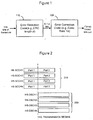
- FIG. 1 illustrates a process flow for forming a typical concatenated code structure at the transmitter of a base station.
- an error detection code is added at 110 to a frame of a data channel, the frame comprising k bits.
- a cyclic redundancy check (CRC) code shown here as having a length p, is used as the error detection code.
- the CRC bits are computed based on the k information bits.
- the CRC code is appended to the frame (e.g., k + p bits), and then passed through error correction encoding at 120.
- the error correction code is, for example, a convolutional code having a rate of 1/r, where r > 1.
- the number of bits equals (r*(k + p)), which are then passed to a modulator and transmitted over a channel.
- An error correction code decoder at the receiver of a user equipment e.g., a mobile station
- the most widely used error detection code is the aforementioned CRC code.
- Standard CRC codes include bit lengths of 8, 12, 16, 24 and/or 32 bits.
- the figure of merit or interest with error detection codes is the probability of an undetected error, i.e., a case where use of the inner error correction code could not correct transmission errors, and the outer error detection code did not detect that the decoded information was erroneous. This is an undetected error because the decoded information is erroneous, but the error detection code did not catch the error.
- the undetected error probability with CRC codes is typically on the order of 2 -L where L is the length of the CRC. Thus, an 8-bit CRC has an undetected error probability of approximately 1/256.
- the overhead associated with using a CRC is dependent on the number of information bits in the frame.
- the number of information bits of a frame such as frame k in FIG. 1 exceeds several hundred bits, and thus any overhead effect of using an 8, 12 or 16-bit CRC is minimal.
- very few bits need to be transmitted per frame and the overhead from using even a length-8 CRC may be excessive.
- One such example is in the transmission of control channel information in wireless high speed data communication systems such as in the High Speed Downlink Packet Access (HSDPA) specification of the Universal Mobile Telecommunication System (UMTS) standard.
- HSDPA High Speed Downlink Packet Access
- UMTS Universal Mobile Telecommunication System
- HSDPA transmission data for several user equipments (hereinafter UEs, also frequently known as mobile stations) are multiplexed on a common high speed downlink shared data channel (HS-DSCH).
- UEs are scheduled on the shared data channel.
- the UEs are scheduled either in a purely time division multiplexed (TDM) manner, where all the available resources (power resources and data channelization codes) are assigned to one UE during a transmission time interval, or among multiple UEs in a transmission time interval (TTI).
- TDM time division multiplexed
- the power resources and data channelization codes are divided up among those UEs, not necessarily in a uniform manner.
- the transmission time interval (TTI) is typically 2ms or 3 timeslots (each timeslot being about 0.667 ms). Scheduling for the UEs is typically accomplished based on some type of information about the channel quality being experienced by the UE.
- control channel carries information related to (a) which UEs have been scheduled to receive a data transmission via a corresponding HS-DSCH (b) what data channel codes, are assigned to each particular UE, and (c) modulation and HARQ-related information. From a system efficiency perspective, a few control channels are defined such that they are shared among all UEs, rather than providing a dedicated control channel per UE.
- each HS-SCCH carries HS-DSCH-related downlink signaling for one UE.
- a UE determines whether an ensuing transmission on any of the HS-DSCHs is intended for itself or not only upon or after decoding information in the HS-SCCHs.
- FIG. 2 illustrates the relationship between HS-SCCHs 210 and their corresponding shared HS-DSCH counterparts 220.
- the number of HS-DSCHs, and therefore the number of HS-SCCHs that may be used, can vary for each TTI, depending on the number of UEs being simultaneously scheduled in the TTI. Accordingly, the configuration of HS-SCCHs and HS-DSCHs in FIG. 2 enables the data channelization codes and power resources to be divided among four simultaneous transmissions.
- control channel data on each HS-SCCH is typically divided into two parts.
- Part I consists of information relating to those data channelization codes that have been assigned to a particular UE, for example.
- Part II data contains HARQ related information, and other transport information.
- each UE must decode up to four (4) HS-SCCHs in every TTI. prior to commencement of data transmission. From a UE processing complexity perspective, it is therefore desirable to limit the number of bits in Part I that require processing, and it is also desirable that the processing be as simple as possible.
- two conditions should be met for each UE. The first is that at each UE. the probability of error detection should be high. In other words, when a transmission is intended for a particular UE, that UE decodes Part I and successfully recognizes that the ensuing data transmission on the corresponding HS-DSCH is for that UE. The second condition to meet is for a probability of false alarm to be low. A false alarm is where a UE decodes Part I and erroneously recognizes that the ensuing data transmission on a corresponding HS-DSCH is for that UE.
- a low probability of detection implies wasted resources, since every missed detection event means that the transmission on the corresponding HS-DSCH is wasted.
- a false alarm event would cause a UE that is NOT scheduled for a particular transmission to begin buffering data and try to decode the information which would waste battery resources at the UE, for example, due to unnecessary processing.
- a UE-specific CRC code is used for error detection on Part 1. Accordingly, the UE will decode Part I bits and apply its unique CRC to check for errors. If there are errors, the UE will assume that the transmission is not intended for it. If use of the CRC detects no errors on Part I of the HS-SCCHs, the UE will decode Part II of the HS-SCCH and begin to buffer and decode the corresponding HS- DSCH.
- Part I of the HS-SCCH usually contains only about 8 information bits, so to use a 12-bit CRC or greater represents a substantial overhead (> 150%).
- the number of Part I bits the UE must process is excessive. For example, for each HS-SCCH having 8 information bits and 12 CRC bits, in order to decode the Part I information for four HS-SCCHs, the UE has to process 80 bits of data, typically within 1 timeslot of a TTI (0.667 ms). This is undesirable, and is essentially the equivalent of processing a peak data rate of 120 kbps just to decode part of the control information
- a conventional solution is to avoid using a CRC for error detection, and instead use a UE-specific scrambling or masking approach followed by calculation of a specific convolutional decoder metric for error detection that is described in further detail below.
- the principle behind this approach is that when the UE descrambles a transmission that is intended for itself, the resultant decoder metric is usually high. However, whenever the UE descrambles a transmission that was intended for some other UE, the decoder metric is usually low. Therefore, scrambling/descrambling to calculate a decoder metric, followed by comparison of the decoder metric to a threshold is one method to achieve error detection when no CRC is used.
- FIG. 3 illustrates a process flow of how a scrambling code is used with a convolutional error correction code.
- the UE-specific scrambling (masking) code "flips" certain bits (1 to 0 and 0 to 1) based on the unique scrambling sequence assigned to the UE.
- Viterbi algorithm for convolutional decoding is a known decoding algorithm that is optimum in the sense that it yields the maximum likelihood (ML) or most likely sequence of bits based on using the output values from the channel.
- Viterbi decoding is the standard technique to decode convolutional codes regardless of whether a CRC is used or not.
- a description of the Viterbi algorithm for decoding convolutional codes may be found in a standard communications textbook such as 'Digital Communications' by J. G. Proakis, 2 nd Edition, McGraw Hill. Some of the concepts are repeated briefly below for convenience.
- a convolutional encoder comprises a number of shift registers or memory elements.
- the number of shift registers is called the constraint length of the code, and each shift register stores exactly 1 bit of information. Each time a new bit comes in, it is read into a leftmost shift register location and the contents of each shift register are shifted to the shift register on the immediate right. The contents of the rightmost shift register are obviously thrown out.
- a convolutional encoder may be viewed as a linear filter that operates on bits.
- a convolutional encoder is also characterized by a code rate.
- the code rate defines how many output bits are produced for every input bit. Therefore a code rate of 1/r implies that for every information bit inputted, r coded bits are output by the encoder.
- the larger the value of r the more powerful the code (i.e. the greater its ability to correct transmission errors).
- how the r output bits are produced needs to be specified; this is given by the connections of shift register elements to exclusive-OR elements.
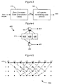
- FIG. 4 is a state diagram of a simple convolutional encoder 400.
- the constraint length defines the number of shift-register elements that are used.
- the shift register elements are part of a memory or shift register in the UE.
- Shift register element 410 will contain the most recently inserted information bit. Each time a new information bit comes in, the previous bits are shifted to the right, so the middle element 420 contains the next-to-most-recent bit and the right most element 430 contains the third most recent bit (e.g., least recent bit).
- XOR operations at 440 and 450 determine how the coded bits are determined. Each time an information bit 415 is input, two coded bits 445 and 455 are output, as shown in FIG. 4.
- FIG. 5 illustrates a trellis diagram 500 to explain how the Viterbi algorithm, and specifically Viterbi decoding, is implemented at the UE.
- States in the trellis represented by black dots in FIG. 5, denote the four possible shift register contents (00, 01. 10 or 11, shown along the left-hand side of the trellis diagram) when a bit comes in. Therefore for binary convolutional codes, the number of states is 2 constraint length - 1 , or 2 k - 1 .
- the center shift register element 420 and rightmost element 430 would therefore be at a state of 00, 01, 11 or 10, depending on the state of the previous two information bits that have been shifted right.
- the first bit in the state is defined as the least recent bit (contents of the rightmost shift register 430) and the second bit (contents of the middle shift register 420) is defined as the next least recent bit. So if the previous two bits were 1 and 0, then the state will be 01.
- the trellis diagram in FIG. 5 assumes that two (2) tail bits are used to terminate the trellis and return the decoder back to the state 00. In general, the number of tail bits required would be equal to the constraint length minus 1 (k-1).
- Each possible transition from one level to the next is called a branch. A sequence of connected branches is called a path through the trellis.
- the Viterbi algorithm proceeds by computing what is termed a "branch metric" at each J level.
- the branch metric is obtained by "correlating" the received bits from the channel with the bits that would have been sent if that branch were taken as the correct channel for the UE. The higher the correlation, the more likely the branch was the correct one. So, in an example where the actual bits received from the channel for a particular J level are 10, then any branch that would have produced a branch metric of 10 at that J level has the highest correlation.
- path metric Branch metrics from previous J levels are summed to yield what is called a path metric.
- Two paths will merge at every state in the trellis and at every level. Viterbi decoding therefore entails comparing the path metrics of the two merging or competing paths and discarding the one with the worse (lowest valued) path metric. Occasionally, due to noise, the incorrect path is chosen over the correct one during one of the aforementioned merging instances. This results in a decoding error. Accordingly, the path that is selected by the Viterbi algorithm is called the survivor or winning path.
- EPMD End Path Metric Difference
- HS-SCCH Performance Results and Improved Structure
- Part 1 a post convolutionally encoded part 1 is scrambled by a UE ID, and the UE ID base scrambling sequence is achieved in two stages by first coding the 10-bit UE ID using a block code derived from a second order subcode to obtain 32 bits, and repeating the first 8 bits of the 32-bit result to produce the remaining 8 bits.
- a method according to the invention is as set out in claim 1. Preferred forms are set out in the dependent claims.
- An efficient and reliable method of detecting errors in control channels of a wireless communication system is provided in order to ensure that for each UE in the system, the probability of error detection is high and the probability of false alarm is low.
- the method decodes at least a portion of a control channel, determines if one or more control channels were successfully received during the decoding, and selects one of the successively received control channels based on at least one calculated metric.
- Part I of each HS-SCCH that is simultaneously received is decoded by a UE.
- the UE includes techniques to determine if one or more of the HS-SCCH's were successfully received during the decoding step. If more than one HS-SCCH was successfully received, the method selects only one of the successively received HS-SCCH's based on calculated path metric differences (PMD) that serve as a "tie-breaking" mechanism to select the correct HS-SCCH for a particular UE.
- PMD path metric differences
- the method utilizes a Yamamoto-Itoh (YI) decoding algorithm in order to determine how many HS-SCCH's were successfully received during the decoding step.
- a base station appends a parity check code to Part I of each HS-SCCH, and the UE uses the parity check code during decoding in order to determine which of the HS-SCCH's were successfully received.
- the parity check code may be used with the aforementioned YI algorithm to provide additional reliability, and then the calculated PMD's are used to break any ties, should multiple HS-SCCHs be successfully received.
- a base station appends a scrambling group code identifier (SCGI) code to Part I of each HS-SCCH, and the UE checks the appended SCGI code during decoding in order to determine which of the HS-SCCH's were successfully received.
- SCGI code may be used with the aforementioned YI algorithm to provide additional reliability, and then the calculated PMD's are used to break any ties, should multiple HS-SCCHs be successfully received.
- Each of the YI algorithm, parity check code approach and SCGI code approach may be referred to as "hard” metrics that give a "good” or "bad” determination on each HS-SCCH..
- the calculated PMD metric is calculated using at least one of several metrics that may be referred to as "soft" metrics.
- the calculated PMD metrics used to select only one HS-SCCH for a UE include one or more of a minimum path metric difference (MPMD) metric, an aggregate path metric difference (APMD) metric, a frequency path metric difference (FPMD) metric, etc.
- MPMD minimum path metric difference
- APMD aggregate path metric difference
- FPMD frequency path metric difference
- each of these metrics are calculated in conjunction with using the aforementioned Viterbi decoding algorithm.
- the UE will decode Part II of the HS-SCCH and will begin buffering data from the shared downlink data channel (HS-DSCH) that corresponds to the selected HS-SCCH.
- HS-DSCH shared downlink data channel
- HSDPA High Speed Downlink Packet Access
- UMTS Universal Mobile Telecommunication System
- the calculated metric at this last level is usually a very noisy metric.
- EPMD is a noisy metric, as to the quality of a frame, is because EPMD only uses a last path metric comparison to determine if a frame is in error or not.
- EPMD does not consider what happened during the "journey" of the eventual winning path as it progressed through the trellis. Accordingly, the EPMD approach does not capture the fact that, at an earlier level in the decoding (as seen in the trellis diagram ofFIG. 5 for example), the winning path may have come very close to another merging or competing path, thus rendering it unreliable.
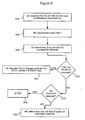
- FIG. 6 is a flowchart illustrating the error detection method in accordance with the invention.
- a UE receives up to four (4) Part I's of 4 HS-SCCHs over simultaneous transmissions (Step S10).
- the UE descrambles Part I in each HS-SCCH and decodes each Part I (Step S20).
- each embodiment described hereafter receives scrambled convolutional codes that are contained in Part I of each HS-SCCH.
- the scrambling is done by the scrambling approach outlined in FIG.
- the UE inverts the scrambling (i.e., descrambles the bits) using its own unique sequence, as described above, and passes the de-scrambled bits to a convolutional decoder in the UE for decoding. This step of descrambling is performed by each of the embodiments discussed hereafter.
- the method utilizes several different algorithms or codes in order to determine (Step S30) how many HS-SCCHs are "good” or "bad". In other words, this step determines if a HS-SCCH was successfully received during the decoding step.
- the different methods which should not be held as limiting, are described in detail below (see e.g., Step S130 in FIG. 7, and Step S230 in FIG. 9).
- Step S40 the number of successfully received HS-SCCHs are determined. If only one HS-SCCH was successfully received during the decoding (output of Step S40 is YES), at Step S45 Part II of the HS-SCCH is decoded and the UE begins buffering data from the HS-DSCH that corresponds to the HS-SCCH.
- Step S34 the processing is stopped (Step S34).
- Step S50 a path metric difference (PMD) is calculated for each remaining good HS-SCCH.
- the path metric difference (PMD) is the aforementioned soft metric that is calculated as a tie-breaking mechanism between successfully received HS-SCCHs in order to select only one HS-SCCH to fully decode.
- Calculated PMDs include calculating a minimum path metric difference (MPMD), an aggregate path metric difference (APMD), and a frequency path metric difference (FPMD), or combinations of one or more of these metrics, in order to select only one HS-SCCH for decoding of Part II, and for buffering data from the HS-DSCH corresponding to the selected HS-SSCH.
- MPMD minimum path metric difference
- APMD aggregate path metric difference
- FPMD frequency path metric difference
- soft metrics from the decoding process are generally preferred over channel quality metrics since they are closer to the decoded bit-stream in the receiver chain at the UE.
- the soft metrics attempt to exploit differences in path metrics of merging paths at each state during Viterbi decoding. As a result, most of the soft metrics are based on a decoding algorithm that will explained in further detail below. In describing these metrics, the following notations are used:
- the method retains a minimum path metric difference value by which the winning path at each state beats a competing or merging path at each state.
- the winning path having the largest minimum difference metric value corresponds to the HS-SCCH that is selected for decoding of Part II and buffering of the data on the corresponding HS-DSCH.
- the intuition for using the MPMD metric is that if at any level during the decoding process a merging path value comes close to a winning path value, then there is less confidence in the decision of choosing that winning path. Since the winning path in the trellis is obviously not known during the decoding process, the current minimum value at each state is stored during the decoding process. Once decoding is complete, an array value of the metric corresponding to the terminating state (state terminated by tail bits) becomes the value of the winning path metric
- the method retains an aggregate sum of the PMD by which the winning path at each state beats a competing or merging path at each state.
- the winning path having the largest aggregate sum corresponds to the HS-SCCH that is selected for decoding of Part II and buffering of the data on the corresponding HS-DSCH.
- the aggregated metric is a scaled version of the average metric.
- the intuition for using the APMD metric is that it represents the confidence with which the survivor or winning path was selected over the merging path at each state in the trellis.
- an array having a length equal to the number of states that contain the current value of ⁇ for each state is required.
- an array value of the metric corresponding to the terminating state becomes the value of the winning path metric.
- the method counts a number of times by which the winning path at each state came within a threshold value of beating a competing path at said state.
- the winning path having the lowest frequency of coming within said threshold corresponds to the HS-SCCH that is selected for decoding of Part II and buffering of the data on the corresponding HS-DSCH.
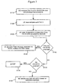
- FIG. 7 is a flowchart illustrating an embodiment of the error detection method in accordance with the invention.
- Steps S110, S120 and S 150 in FIG. 7 are the same as Steps S10, S20, and S50 in FIG. 6, thus a detailed discussion of these steps is omitted.
- Part I of the HS-SCCH is encoded using the Yamamoto-Itoh (YI) encoding algorithm and the method uses a Yamamoto-Itoh (YI) decoding algorithm in order to determine (Step S130) how many HS-SCCHs have been successfully received at the UE.
- Yamamoto-Itoh YI
- YI Yamamoto-Itoh
- the YI decoding algorithm offers a superior approach to error detection in wireless communication systems employing frame-based communication.
- the YI algorithm would retain a flag indicating whether the winning path at that state has come within a threshold of a merging path. If the answer is YES, the flag is set to "unreliable”; and if the answer is NO, the flag is set to "reliable”.
- the flag for the winning path is checked. If a flag in the winning path has been set to "unreliable", the decoding is considered to have failed. In the context of decoding a HS-SCCH, this means that the UE will determine that it is not the intended recipient.
- a UE may decode Part I data portions in each of the 4 HS-SCCHs, and determine by using the YI algorithm of Step S 130 that more than one of the decoded Part I's are evaluated as reliable.
- Step S145 Part II of the HS-SCCH is decoded and the UE begins buffering data from the HS-DSCH that corresponds to the HS-SCCH. If either no HS-SCCH was a successor or more than one HS-SCCH was successfully received (NO at Step S140), the UE determines if no HS-SCCH was successfully received at Step S133. If the output of Step S133 is YES, the processing is stopped (Step S134).
- Step S 150 the method must select only one HS-SCCH (Step S 150). As there can be only one transmission to a UE per TTI, clearly one of those HS-SCCHs is a false alarm. Accordingly, in accordance with this embodiment of the invention, the UE applies the "tie-breaking" procedure discussed above with respect to Steps S50/S 150 in order to select the one HS-SCCH for that UE.
- FIG. 8 is a partial trellis diagram to illustrate the operation of the YI algorithm.
- the YI algorithm can be classified as a hard metric indicating a good result (e.g., the transmission is intended for that UE and the UE successfully determines that the transmission is intended for it), or bad result (e.g., the UE determines that it is not the intended recipient).
- the aforementioned soft metrics act as a tie-breaking mechanism to determine the correct HS-SCCH, and hence correct HS-DSCH. Therefore, the MPMD, APMD and FPMD soft metrics, based on path metric differences, may be calculated in Step S150 for use as convolutional codes so that the UE decodes the correct HS-SCCH.
- the Y1 algorithm provides an alternative method for performing error detection.
- the algorithm works in conjunction with Viterbi decoding of convolutional codes with very little processing overhead.
- the YI decoding algorithm is based on the principle that when two paths merge in the trellis and are close in terms of their path metrics, selection of the one path over the other is more prone to error.
- path a has a label C at level (j-1) and the difference between ⁇ j(a) and ⁇ j(b) is greater than or equal to A, a threshold value that is a given positive constant, then let path "a" survive (survivor path) with label C (e.g., reliable). Otherwise, path a survives with label X (e.g., unreliable). Paths other than path "a" at that state are discarded.
- a survivor or winning path at each state is selected by the maximum likelihood decision in exactly the same way as paths are selected using the ordinary Viterbi decoding algorithm.
- the YI algorithm reduces to the ordinary Viterbi decoding algorithm if A, the threshold value, is equal to zero.
- paths a, b, c and d are survivor paths with label C at level j-1.
- paths a-e and c-f merge at one state
- paths b-g and d-h merge at another.
- the above procedure is continued until the entire frame is decoded. At that point, if the survivor path with the best path metric (the chosen path) is labeled X, an error is declared. Otherwise, the frame is accepted as being good.
- the YI algorithm operates on the intuition that the further apart the path metrics being compared at a state are from each other (winning path to other merging path) the greater the confidence in the chosen survivor (winning) path.
- FIG. 9 is a flowchart illustrating another embodiment of the error detection method in accordance with the invention.
- Steps S210, S220, S231 and S250 are the same as Steps S10, S20, S40 and S50 in FIG. 6, thus a detailed discussion of these steps is omitted.
- the method uses a parity check code in order to determine (at Step 5230) how many HS-SCCHs have been successfully received by the UE.
- parity check code In a parity check code each parity check bit is computed by an exclusive OR operation on 2 or more of the information bits. Depending on how each parity check bit is computed a variety of parity check codes result for the same number of parity bits. For example, assuming there are three information bits and two parity check bits, one possibly parity check code would be where the first parity check bit is computed by exclusive-OR of the 1 st and 3 rd information bits and the second parity check bit is computed by exclusive-OR of the 2 nd and 3 rd bit.
- Another parity check code may compute the first parity bit using the 1 st and 2 nd information bits and the 2 nd parity bit is computed using the 1 st and 3 rd information bit.
- One or more parity bits may also simply be repetitions of certain information bits.
- FIG. 10 illustrates a process flow of how parity check code bits are used in conjunction with the scrambling code at the base station. For example, consider a Part I of an HS-SCCH having 8 information bits, with 4 parity check code bits computed and appended to the 8 information bits in block 1010. For each HS-SCCH, the information bits with appended parity bits are convolutionally encoded at block 1020 and then scrambled at block 1030 using the scrambling approach described with reference to FIG. 3. For 4 HS-SCCHs this increases the peak data rate processing to be 72 Kbps, which is still substantially better than what would be required using a 12-bit or higher CRC code.
- a UE may decode Part I data portions in each of the 4 HS-SCCHs, and in Step S230 determine by using the parity check code that one or more of the decoded Part Is are evaluated as reliable. Specifically, the parity check code decoded by the UE is used to test if any of the HS-SCCHs pass. If one SCCH was a success (YES at Step 231), as in the previous embodiment, then Step S245 is performed-decode Part II for that HS-SCCH and begin buffering data from the corresponding HS-DSCH.
- Step S231 If either no HS-SCCH was a successor or more than one HS-SCCH was successfully received (NO at Step S231), the UE determines if no HS-SCCH was successfully received at Step S233. If the output of Step S233 is YES, the processing is stopped (Step S234). If more than one HS-SCCH was a success (NO at Step 233), then the method uses the YI algorithm in a Step S235 to obtain a reliable or unreliable indicator of the HS-SCCHs and processing returns to Step S231.
- Step S231 If at Step S231 exactly one SCCH was a success (output of Step S231 is YES), then at Step S245 decode Part II for that HS-SCCH and begin buffering data from the corresponding HS-DSCH. If no HS-SCCHs passed or if more than one HS-SCCH still passed, (output of step S233 is NO in the second iteration, illustrated by dotted lines) then in step S250, the APMD, FPMD and/or MPMD metrics are calculated and used to break ties so as to select only one HS-SCCH to decode.
- the UE may eventually apply the "tie-breaking" procedure discussed initially above at Step S50 of FIG. 6 in order to select the one HS-SCCH for that UE.
- error detection is performed using an alternative code to the parity check code, called a scrambling code group identifier (SCGI) code.
- SCGI scrambling code group identifier
- the SCGI code is appended to each Part 1 of a HS-SCCH as in FIG. 10.
- the SCGI identifies the scrambling code group to which the HS-SCCH transmission belongs, and is transmitted along with Part I.
- Each UE decodes Part I on each HS-SCCH and checks if the SCGI corresponds to its UE-specific scrambling code group. If none of the SCGI codes match the UE-specific scrambling code group, the UE determines that none of the HS-SCCHs are intended for it.
- the principle behind the above approach is to divide the total set of scrambling codes into groups. If a p-bit SCGI is used, then 2 p groups are formed.
- the assignment of scrambling codes to UEs balances the number of UEs in each scrambling code group. This reduces the likelihood of simultaneous transmissions to UEs in the same code group, thereby improving the false alarm probability.
- the SCGI approach is relatively simple to implement at the base station and at the UE, since unlike the parity check code, all that is required is the insertion or appending of the SCGI bit field to the information bits prior to the encoding of Part I of a HS-SCCH.
Description
- The invention relates generally to wireless communication systems and, more particularly, to error detection methods for evaluating information that is transmitted in control channels of such systems.
- Almost all wireless communication systems employ "frame-based" communication, where a certain number of bits, defined as a frame, are channel encoded together and transmitted. Most systems employ concatenated coding for each frame with an inner error correction code such as a convolutional or Turbo error correction code and an outer error detection code.
- FIG. 1 illustrates a process flow for forming a typical concatenated code structure at the transmitter of a base station. As shown, an error detection code is added at 110 to a frame of a data channel, the frame comprising k bits. Typically a cyclic redundancy check (CRC) code, shown here as having a length p, is used as the error detection code. The CRC bits are computed based on the k information bits. The CRC code is appended to the frame (e.g., k + p bits), and then passed through error correction encoding at 120. The error correction code is, for example, a convolutional code having a rate of 1/r, where r > 1. After error correction encoding, the number of bits equals (r*(k + p)), which are then passed to a modulator and transmitted over a channel. An error correction code decoder at the receiver of a user equipment (e.g., a mobile station) will attempt to correct any bit errors that take place on the channel.
- In most cases, a frame is discarded when the receiver detects an error, which is uncorrectable, in the transmission based on the error detection code. This results in a loss or delay of information, depending on whether a retransmission is subsequently carried out. The most widely used error detection code is the aforementioned CRC code. Standard CRC codes include bit lengths of 8, 12, 16, 24 and/or 32 bits. The figure of merit or interest with error detection codes is the probability of an undetected error, i.e., a case where use of the inner error correction code could not correct transmission errors, and the outer error detection code did not detect that the decoded information was erroneous. This is an undetected error because the decoded information is erroneous, but the error detection code did not catch the error. The undetected error probability with CRC codes is typically on the order of 2-L where L is the length of the CRC. Thus, an 8-bit CRC has an undetected error probability of approximately 1/256.
- The overhead associated with using a CRC is dependent on the number of information bits in the frame. Typically, the number of information bits of a frame such as frame k in FIG. 1 exceeds several hundred bits, and thus any overhead effect of using an 8, 12 or 16-bit CRC is minimal. However, in certain applications very few bits need to be transmitted per frame and the overhead from using even a length-8 CRC may be excessive. One such example is in the transmission of control channel information in wireless high speed data communication systems such as in the High Speed Downlink Packet Access (HSDPA) specification of the Universal Mobile Telecommunication System (UMTS) standard.
- In HSDPA, transmission data for several user equipments (hereinafter UEs, also frequently known as mobile stations) are multiplexed on a common high speed downlink shared data channel (HS-DSCH). High data rates are obtained through scheduling, adaptive modulation and coding, and hybrid automatic repeat request (H-ARQ) as is known. UEs are scheduled on the shared data channel. The UEs are scheduled either in a purely time division multiplexed (TDM) manner, where all the available resources (power resources and data channelization codes) are assigned to one UE during a transmission time interval, or among multiple UEs in a transmission time interval (TTI). When transmitting to multiple UEs in a TTI, the power resources and data channelization codes are divided up among those UEs, not necessarily in a uniform manner. In the UMTS standard, the transmission time interval (TTI) is typically 2ms or 3 timeslots (each timeslot being about 0.667 ms). Scheduling for the UEs is typically accomplished based on some type of information about the channel quality being experienced by the UE.
- An important component of these high speed wireless systems is the use of a control channel. The control channel carries information related to (a) which UEs have been scheduled to receive a data transmission via a corresponding HS-DSCH (b) what data channel codes, are assigned to each particular UE, and (c) modulation and HARQ-related information. From a system efficiency perspective, a few control channels are defined such that they are shared among all UEs, rather than providing a dedicated control channel per UE.
- An exemplary configuration is to define up to M high speed shared control channels (HS-SCCHs) for simultaneous transmissions, where M=4, for example. For each TTI, each HS-SCCH carries HS-DSCH-related downlink signaling for one UE. The number of HS-SCCHs may range from a minimum of one HS-SCCH (M=1) to a maximum of four HS-SCCH's (M=4). This is the number of HS-SCCH's as seen from the UE's point-of-view. In other words, a UE determines whether an ensuing transmission on any of the HS-DSCHs is intended for itself or not only upon or after decoding information in the HS-SCCHs.
- FIG. 2 illustrates the relationship between HS-
SCCHs 210 and their corresponding shared HS-DSCH counterparts 220. In FIG. 2, each HS-SCCHx (x=1 to 4) carries information pertinent to a corresponding HS-DSCHx (x=1 to 4). The number of HS-DSCHs, and therefore the number of HS-SCCHs that may be used, can vary for each TTI, depending on the number of UEs being simultaneously scheduled in the TTI. Accordingly, the configuration of HS-SCCHs and HS-DSCHs in FIG. 2 enables the data channelization codes and power resources to be divided among four simultaneous transmissions. - Referring again to FIG. 2, control channel data on each HS-SCCH is typically divided into two parts. Part I consists of information relating to those data channelization codes that have been assigned to a particular UE, for example. Part II data contains HARQ related information, and other transport information. To maintain complexity low at the UE, HS-SCCH designs typically allow Part I information to be transmitted prior to the commencement (i.e., before t=0) of data transmission, as shown in FIG. 2. Accordingly, with the current configuration, each UE must decode Part I on every HS-SCCH, in every TTI. in order to determine (a) whether or not the transmission was intended for that particular UE, and (b) if the transmission was intended for that particular UE, the UE must decode Part I and figure out what channelization codes the corresponding HS-DSCH will arrive on.
- Therefore, each UE must decode up to four (4) HS-SCCHs in every TTI. prior to commencement of data transmission. From a UE processing complexity perspective, it is therefore desirable to limit the number of bits in Part I that require processing, and it is also desirable that the processing be as simple as possible. At the same time, two conditions should be met for each UE. The first is that at each UE. the probability of error detection should be high. In other words, when a transmission is intended for a particular UE, that UE decodes Part I and successfully recognizes that the ensuing data transmission on the corresponding HS-DSCH is for that UE. The second condition to meet is for a probability of false alarm to be low. A false alarm is where a UE decodes Part I and erroneously recognizes that the ensuing data transmission on a corresponding HS-DSCH is for that UE.
- A low probability of detection implies wasted resources, since every missed detection event means that the transmission on the corresponding HS-DSCH is wasted. A false alarm event would cause a UE that is NOT scheduled for a particular transmission to begin buffering data and try to decode the information which would waste battery resources at the UE, for example, due to unnecessary processing.
- In order to ensure the above two conditions are met, typically a UE-specific CRC code is used for error detection on
Part 1. Accordingly, the UE will decode Part I bits and apply its unique CRC to check for errors. If there are errors, the UE will assume that the transmission is not intended for it. If use of the CRC detects no errors on Part I of the HS-SCCHs, the UE will decode Part II of the HS-SCCH and begin to buffer and decode the corresponding HS- DSCH. - Standard CRC codes having bit lengths of 12 bits or higher usually achieve acceptable detection/false alarm performance. However, Part I of the HS-SCCH usually contains only about 8 information bits, so to use a 12-bit CRC or greater represents a substantial overhead (> 150%). Furthermore, the number of Part I bits the UE must process is excessive. For example, for each HS-SCCH having 8 information bits and 12 CRC bits, in order to decode the Part I information for four HS-SCCHs, the UE has to process 80 bits of data, typically within 1 timeslot of a TTI (0.667 ms). This is undesirable, and is essentially the equivalent of processing a peak data rate of 120 kbps just to decode part of the control information
- A conventional solution is to avoid using a CRC for error detection, and instead use a UE-specific scrambling or masking approach followed by calculation of a specific convolutional decoder metric for error detection that is described in further detail below. The principle behind this approach is that when the UE descrambles a transmission that is intended for itself, the resultant decoder metric is usually high. However, whenever the UE descrambles a transmission that was intended for some other UE, the decoder metric is usually low. Therefore, scrambling/descrambling to calculate a decoder metric, followed by comparison of the decoder metric to a threshold is one method to achieve error detection when no CRC is used.
- FIG. 3 illustrates a process flow of how a scrambling code is used with a convolutional error correction code. The UE-specific scrambling (masking) code "flips" certain bits (1 to 0 and 0 to 1) based on the unique scrambling sequence assigned to the UE.
- For example, in FIG. 3 suppose the scrambling sequence in
block 320 is 0101 and the output bits from the convolutional code inblock 310 are 1101, If the scrambling code flips the output bits, then the sequence after scrambling will be 1 000. When the UE decodes this sequence, the UE will invert the scrambling using its own sequence, and then pass the resulting information through a convolutional decoder. The effect of this scrambling is that when the transmission is not intended for the UE, path metrics calculated using a Viterbi decoding algorithm of the convolutional code are quite low. A discussion of the Viterbi algorithm, which is utilized by the above-mentioned UE-specific scrambling or masking approach to error detection, as well as a discussion of path metrics follows. - The Viterbi algorithm for convolutional decoding is a known decoding algorithm that is optimum in the sense that it yields the maximum likelihood (ML) or most likely sequence of bits based on using the output values from the channel. Viterbi decoding is the standard technique to decode convolutional codes regardless of whether a CRC is used or not. A description of the Viterbi algorithm for decoding convolutional codes may be found in a standard communications textbook such as 'Digital Communications' by J. G. Proakis, 2nd Edition, McGraw Hill. Some of the concepts are repeated briefly below for convenience.
- A convolutional encoder comprises a number of shift registers or memory elements. The number of shift registers is called the constraint length of the code, and each shift register stores exactly 1 bit of information. Each time a new bit comes in, it is read into a leftmost shift register location and the contents of each shift register are shifted to the shift register on the immediate right. The contents of the rightmost shift register are obviously thrown out. Thus, a convolutional encoder may be viewed as a linear filter that operates on bits.
- A convolutional encoder is also characterized by a code rate. In general, the code rate defines how many output bits are produced for every input bit. Therefore a code rate of 1/r implies that for every information bit inputted, r coded bits are output by the encoder. Thus, the larger the value of r, the more powerful the code (i.e. the greater its ability to correct transmission errors). Finally, how the r output bits are produced needs to be specified; this is given by the connections of shift register elements to exclusive-OR elements.
- FIG. 4 is a state diagram of a simple
convolutional encoder 400.Convolutional encoder 400 has a constraint length k=3 and a rate=1/2, as is known. The constraint length defines the number of shift-register elements that are used. The shift register elements are part of a memory or shift register in the UE. In FIG. 4, there are threeshift register elements Shift register element 410 will contain the most recently inserted information bit. Each time a new information bit comes in, the previous bits are shifted to the right, so themiddle element 420 contains the next-to-most-recent bit and the rightmost element 430 contains the third most recent bit (e.g., least recent bit). XOR operations at 440 and 450 determine how the coded bits are determined. Each time aninformation bit 415 is input, two codedbits - FIG. 5 illustrates a trellis diagram 500 to explain how the Viterbi algorithm, and specifically Viterbi decoding, is implemented at the UE. States in the trellis, represented by black dots in FIG. 5, denote the four possible shift register contents (00, 01. 10 or 11, shown along the left-hand side of the trellis diagram) when a bit comes in. Therefore for binary convolutional codes, the number of states is 2constraint length - 1, or 2k - 1. For each information bit inputted, the center
shift register element 420 andrightmost element 430 would therefore be at a state of 00, 01, 11 or 10, depending on the state of the previous two information bits that have been shifted right. The first bit in the state is defined as the least recent bit (contents of the rightmost shift register 430) and the second bit (contents of the middle shift register 420) is defined as the next least recent bit. So if the previous two bits were 1 and 0, then the state will be 01. - The trellis diagram is provided for the convolutional coding shown in FIG. 4, and is drawn for seven (7) levels (levels represented by J, where J=1 to 7)
corresponding to 7 information bits The trellis diagram in FIG. 5 assumes that two (2) tail bits are used to terminate the trellis and return the decoder back to thestate 00. In general, the number of tail bits required would be equal to the constraint length minus 1 (k-1). - Each level J (J=1 to 7) across the top of the trellis diagram in FIG. 5 corresponds to each information bit. Prior to inputting the first bit, the two
shift register elements state 00. On the other hand, if the first information bit intodecoder 400 at J=0 is a 1, then thedecoder 400 moves tostate 01 at level J=1. Each possible transition from one level to the next is called a branch. A sequence of connected branches is called a path through the trellis. - The Viterbi algorithm proceeds by computing what is termed a "branch metric" at each J level. The branch metric is obtained by "correlating" the received bits from the channel with the bits that would have been sent if that branch were taken as the correct channel for the UE. The higher the correlation, the more likely the branch was the correct one. So, in an example where the actual bits received from the channel for a particular J level are 10, then any branch that would have produced a branch metric of 10 at that J level has the highest correlation.
- Branch metrics from previous J levels are summed to yield what is called a path metric. The higher the value of the path metric, the more likely that the path metric corresponds to the actual transmitted sequence of bits. Two paths will merge at every state in the trellis and at every level. Viterbi decoding therefore entails comparing the path metrics of the two merging or competing paths and discarding the one with the worse (lowest valued) path metric. Occasionally, due to noise, the incorrect path is chosen over the correct one during one of the aforementioned merging instances. This results in a decoding error. Accordingly, the path that is selected by the Viterbi algorithm is called the survivor or winning path.
- There is at most one winning path per state, per level. Since tail bits are used, the state at the last level will always be an all-zero state. In the example, 2 tail bits are used and the state at the last level is 00. As stated before, two paths will merge at the 00 state at the last level. Accordingly, the Viterbi decoding algorithm selects the path with the larger path metric at this last (J=7) level. This path now is the eventual winning path and represents the "most likely" sequence of transmitted bits.
- Accordingly, in the scrambling approach where no CRC is used for error detection, error detection is performed using Viterbi decoding with the scrambling approach. In this context, the conventional method is to determine a path metric difference between the merging paths in the last level (e.g. J=7 in the trellis diagram of FIG. 5). If that calculated path metric difference is below a predetermined threshold, then the decoding is considered unreliable, and the UE declares that the transmission on that particular HS-SCCH was not intended for it. This is termed an End Path Metric Difference (EPMD) approach to error detection. The EPMD approach avoids transmission of CRC bits and thus lowers the processing requirement at the UE.
- "HS-SCCH: Performance Results and Improved Structure," illustrates performance of a first part (Part 1) of a conventional HS-SCCH coding structure in terms of probability Pm and probability of false alarm Pf, as compared to the second part (Part 2) of HS-SCCH. As illustrated, a post convolutionally encoded
part 1 is scrambled by a UE ID, and the UE ID base scrambling sequence is achieved in two stages by first coding the 10-bit UE ID using a block code derived from a second order subcode to obtain 32 bits, and repeating the first 8 bits of the 32-bit result to produce the remaining 8 bits. - Motorola and Philips: 'Way Forward on HS-SCCH', TDOC R1-02-0463 of, 3GPP TSG RAN WG1, <http://www.3gpp.org>, 18th February - 22nd February 2002, pages 1-2, is directed to a coding scheme for controlled channel signaling for a HS-DSCH (high-speed downlink shared channel), with regard to the decoding of the shared controlled channel at the UE. A part of each shared control channel is descrambled by the UE, and a metric difference between the likely paths during Viterbi decoding process is taken as a reliable basis for the validity of a shared control channel.
- A method according to the invention is as set out in
claim 1. Preferred forms are set out in the dependent claims. - An efficient and reliable method of detecting errors in control channels of a wireless communication system is provided in order to ensure that for each UE in the system, the probability of error detection is high and the probability of false alarm is low. In an embodiment, the method decodes at least a portion of a control channel, determines if one or more control channels were successfully received during the decoding, and selects one of the successively received control channels based on at least one calculated metric.
- More particularly, Part I of each HS-SCCH that is simultaneously received (i.e., 4 HS-SCCH's) is decoded by a UE. The UE includes techniques to determine if one or more of the HS-SCCH's were successfully received during the decoding step. If more than one HS-SCCH was successfully received, the method selects only one of the successively received HS-SCCH's based on calculated path metric differences (PMD) that serve as a "tie-breaking" mechanism to select the correct HS-SCCH for a particular UE.
- In an embodiment, the method utilizes a Yamamoto-Itoh (YI) decoding algorithm in order to determine how many HS-SCCH's were successfully received during the decoding step. In another embodiment, a base station appends a parity check code to Part I of each HS-SCCH, and the UE uses the parity check code during decoding in order to determine which of the HS-SCCH's were successfully received. The parity check code may be used with the aforementioned YI algorithm to provide additional reliability, and then the calculated PMD's are used to break any ties, should multiple HS-SCCHs be successfully received.
- In a further embodiment, a base station appends a scrambling group code identifier (SCGI) code to Part I of each HS-SCCH, and the UE checks the appended SCGI code during decoding in order to determine which of the HS-SCCH's were successfully received. The SCGI code may be used with the aforementioned YI algorithm to provide additional reliability, and then the calculated PMD's are used to break any ties, should multiple HS-SCCHs be successfully received. Each of the YI algorithm, parity check code approach and SCGI code approach may be referred to as "hard" metrics that give a "good" or "bad" determination on each HS-SCCH..
- The calculated PMD metric is calculated using at least one of several metrics that may be referred to as "soft" metrics. The calculated PMD metrics used to select only one HS-SCCH for a UE include one or more of a minimum path metric difference (MPMD) metric, an aggregate path metric difference (APMD) metric, a frequency path metric difference (FPMD) metric, etc. As will be explained below, each of these metrics are calculated in conjunction with using the aforementioned Viterbi decoding algorithm. For the selected HS-SCCH, the UE will decode Part II of the HS-SCCH and will begin buffering data from the shared downlink data channel (HS-DSCH) that corresponds to the selected HS-SCCH.
- The present invention will become more fully understood from the detailed description given hereinbelow and the accompanying drawings, wherein like elements are represented by like reference numerals, which are given by way of illustration only and thus are not limitative of the present invention and wherein:
- FIG. 1 illustrates a process flow for forming a typical concatenated code structure that is transmitted by a base station in accordance with the invention;
- FIG. 2 illustrates the relationship between shared control channels and shared downlink data channels in accordance with the invention;
- FIG. 3 illustrates use of a scrambling code with a convolutional error correction code;
- FIG. 4 is a state diagram of a simple convolutional encoder;
- FIG. 5 illustrates a trellis diagram to explain how the Viterbi algorithm is implemented in a decoder of a UE:
- FIG. 6 is a flowchart illustrating the error detection method in accordance with the invention;
- FIG. 7 is a flowchart illustrating one embodiment of the error detection method in accordance with the invention;
- FIG. 8 is a trellis diagram for illustrating how the method of FIG. 7 successfully decodes the correct shared control channel; and
- FIG. 9 is a flowchart illustrating another embodiment of the error detection method in accordance with the invention; and
- FIG. 10 illustrates a process flow of how parity check code bits are used in conjunction with the scrambling code at the base station.
- Although the principles of the invention are particularly well-suited for wireless communications systems based on the well-known High Speed Downlink Packet Access (HSDPA) specification in the Universal Mobile Telecommunication System (UMTS) standard, and will be described in this exemplary context, it should be noted that the embodiments shown and described herein are meant to be illustrative only and not limiting in any way. As such, various modifications will be apparent to those skilled in the art for application to other transmission systems and are contemplated by the teachings herein. Additionally where used below, user equipment (UE) is synonymous to a mobile station in a wireless communication network.
- Accordingly, there is now described a method for detecting errors in control channels of a wireless communication system that overcomes the problems of inadequate error detection and false alarm performance, which are present in the conventional scrambling or EPMD approaches described above. The conventional scrambling or EPMD approach to error detection usually does not yield adequate error detection/false alarm performance. This is because the approach is based on a path metric difference calculated at only the last level in the trellis.
- The calculated metric at this last level is usually a very noisy metric. The reason why EPMD is a noisy metric, as to the quality of a frame, is because EPMD only uses a last path metric comparison to determine if a frame is in error or not. EPMD does not consider what happened during the "journey" of the eventual winning path as it progressed through the trellis. Accordingly, the EPMD approach does not capture the fact that, at an earlier level in the decoding (as seen in the trellis diagram ofFIG. 5 for example), the winning path may have come very close to another merging or competing path, thus rendering it unreliable.
- FIG. 6 is a flowchart illustrating the error detection method in accordance with the invention. In FIG. 6, initially a UE receives up to four (4) Part I's of 4 HS-SCCHs over simultaneous transmissions (Step S10). The UE descrambles Part I in each HS-SCCH and decodes each Part I (Step S20). In accordance with the method of the invention, each embodiment described hereafter receives scrambled convolutional codes that are contained in Part I of each HS-SCCH. The scrambling is done by the scrambling approach outlined in FIG. 3 At the UE, the UE inverts the scrambling (i.e., descrambles the bits) using its own unique sequence, as described above, and passes the de-scrambled bits to a convolutional decoder in the UE for decoding. This step of descrambling is performed by each of the embodiments discussed hereafter.
- The method utilizes several different algorithms or codes in order to determine (Step S30) how many HS-SCCHs are "good" or "bad". In other words, this step determines if a HS-SCCH was successfully received during the decoding step. The different methods, which should not be held as limiting, are described in detail below (see e.g., Step S130 in FIG. 7, and Step S230 in FIG. 9). At Step S40, the number of successfully received HS-SCCHs are determined. If only one HS-SCCH was successfully received during the decoding (output of Step S40 is YES), at Step S45 Part II of the HS-SCCH is decoded and the UE begins buffering data from the HS-DSCH that corresponds to the HS-SCCH.
- If either no HS-SCCH was a successor or more than one HS-SCCH was successfully received (NO at Step S40), the UE determines if no HS-SCCH was successfully received at Step S33. If the output of Step S33 is YES, the processing is stopped (Step S34).
- If more than one HS-SCCH was a success (NO at Step S33), meaning that two or more HS-SCCHs were successfully received, the method must select only one HS-SCCH (Step S50) based on a calculated metric. This is because there can be only one correct HS-SCCH for each UE, and hence only one HS-DSCH with the intended transmission for that UE. In Step S50 a path metric difference (PMD) is calculated for each remaining good HS-SCCH. The path metric difference (PMD) is the aforementioned soft metric that is calculated as a tie-breaking mechanism between successfully received HS-SCCHs in order to select only one HS-SCCH to fully decode.
- Calculated PMDs include calculating a minimum path metric difference (MPMD), an aggregate path metric difference (APMD), and a frequency path metric difference (FPMD), or combinations of one or more of these metrics, in order to select only one HS-SCCH for decoding of Part II, and for buffering data from the HS-DSCH corresponding to the selected HS-SSCH. As will be discussed in further detail below, each of the MPMD, APMD and FPMD metric values are determined in conjunction with using the Viterbi decoding algorithm discussed above in order to determine a winning path at each of the states.
- These soft metrics from the decoding process are generally preferred over channel quality metrics since they are closer to the decoded bit-stream in the receiver chain at the UE. In the case of convolutional codes, the soft metrics attempt to exploit differences in path metrics of merging paths at each state during Viterbi decoding. As a result, most of the soft metrics are based on a decoding algorithm that will explained in further detail below. In describing these metrics, the following notations are used:
- (a) λj(1) is the path metric of the chosen (decoded) path at the jth level in the trellis; and
- (b) λj(2) is the path metric of the of the path that merges with the chosen path at the jth level in the trellis.
- Under an assumption that the path labeled "1" is the chosen path at each level, λj(1) will always be larger than λj(2) The actual values of the path metrics are not of much importance, as compared to their relative values and the corresponding number of decoded bit-errors.
- To calculate the MPMD metric, the method retains a minimum path metric difference value by which the winning path at each state beats a competing or merging path at each state. The winning path having the largest minimum difference metric value corresponds to the HS-SCCH that is selected for decoding of Part II and buffering of the data on the corresponding HS-DSCH.
- In order to determine the MPMD metric, in addition to determining the survivor path by Viterbi decoding, the metric, λj(1)-λj(2) is retained at the time of comparison. Assuming that there are N levels in the trellis, where N represents the number of information bits and tail bits in a frame, the MPMD is defined as:

where j is the level index. At the end of Viterbi decoding, the selected path is evaluated and the minimum metric for that path is chosen as the winning path metric, or frame quality metric. The intuition for using the MPMD metric is that if at any level during the decoding process a merging path value comes close to a winning path value, then there is less confidence in the decision of choosing that winning path. Since the winning path in the trellis is obviously not known during the decoding process, the current minimum value at each state is stored during the decoding process. Once decoding is complete, an array value of the metric corresponding to the terminating state (state terminated by tail bits) becomes the value of the winning path metric - For the APMD metric, the method retains an aggregate sum of the PMD by which the winning path at each state beats a competing or merging path at each state. The winning path having the largest aggregate sum corresponds to the HS-SCCH that is selected for decoding of Part II and buffering of the data on the corresponding HS-DSCH.
- The sum of the YI algorithm metrics at each comparison in the trellis is evaluated. In the notation defined above with respect to MPMD, the APMD metric is given by

- Since the number of levels in the trellis per frame is fixed, the aggregated metric is a scaled version of the average metric. The intuition for using the APMD metric is that it represents the confidence with which the survivor or winning path was selected over the merging path at each state in the trellis. As in the case of the minimum metric, an array having a length equal to the number of states that contain the current value of Λ for each state is required. At the end of the decoding process, an array value of the metric corresponding to the terminating state (state terminated by the tail bits) becomes the value of the winning path metric.
- For the FPMD metric, the method counts a number of times by which the winning path at each state came within a threshold value of beating a competing path at said state. The winning path having the lowest frequency of coming within said threshold corresponds to the HS-SCCH that is selected for decoding of Part II and buffering of the data on the corresponding HS-DSCH.
- FIG. 7 is a flowchart illustrating an embodiment of the error detection method in accordance with the invention. As described with respect to FIG. 6, Steps S110, S120 and S 150 in FIG. 7 are the same as Steps S10, S20, and S50 in FIG. 6, thus a detailed discussion of these steps is omitted. However, in this embodiment, Part I of the HS-SCCH is encoded using the Yamamoto-Itoh (YI) encoding algorithm and the method uses a Yamamoto-Itoh (YI) decoding algorithm in order to determine (Step S130) how many HS-SCCHs have been successfully received at the UE.
- The YI decoding algorithm, known in literature, offers a superior approach to error detection in wireless communication systems employing frame-based communication. At every level and every state in the trellis diagram of FIG. 5 for example, the YI algorithm would retain a flag indicating whether the winning path at that state has come within a threshold of a merging path. If the answer is YES, the flag is set to "unreliable"; and if the answer is NO, the flag is set to "reliable". At the end of decoding, the flag for the winning path is checked. If a flag in the winning path has been set to "unreliable", the decoding is considered to have failed. In the context of decoding a HS-SCCH, this means that the UE will determine that it is not the intended recipient.
- In the scrambling based approach, using the YI algorithm instead of EPMD results in much better detection/false alarm probability. However, in the context of decoding a HS-SCCH, the YI decoding algorithm alone may still not be sufficient. Therefore, refining, "composite metrics" calculations may be desirable.
- For example, a UE may decode Part I data portions in each of the 4 HS-SCCHs, and determine by using the YI algorithm of Step S 130 that more than one of the decoded Part I's are evaluated as reliable.
- If only one HS-SCCH was successfully received during the decoding (output of
Step S 140 is YES), at Step S145 Part II of the HS-SCCH is decoded and the UE begins buffering data from the HS-DSCH that corresponds to the HS-SCCH. If either no HS-SCCH was a successor or more than one HS-SCCH was successfully received (NO at Step S140), the UE determines if no HS-SCCH was successfully received at Step S133. If the output of Step S133 is YES, the processing is stopped (Step S134). - If more than one HS-SCCH was a success (NO at Step S133), this means that two or more HS-SCCHs were successfully received, the method must select only one HS-SCCH (Step S 150). As there can be only one transmission to a UE per TTI, clearly one of those HS-SCCHs is a false alarm. Accordingly, in accordance with this embodiment of the invention, the UE applies the "tie-breaking" procedure discussed above with respect to Steps S50/S 150 in order to select the one HS-SCCH for that UE.
- FIG. 8 is a partial trellis diagram to illustrate the operation of the YI algorithm. The YI algorithm can be classified as a hard metric indicating a good result (e.g., the transmission is intended for that UE and the UE successfully determines that the transmission is intended for it), or bad result (e.g., the UE determines that it is not the intended recipient). Accordingly, where more than one HS-SCCH is evaluated as good, the aforementioned soft metrics act as a tie-breaking mechanism to determine the correct HS-SCCH, and hence correct HS-DSCH. Therefore, the MPMD, APMD and FPMD soft metrics, based on path metric differences, may be calculated in Step S150 for use as convolutional codes so that the UE decodes the correct HS-SCCH.
- For applications where the use of a CRC for error detection is expensive, the Y1 algorithm provides an alternative method for performing error detection. The algorithm works in conjunction with Viterbi decoding of convolutional codes with very little processing overhead. The YI decoding algorithm is based on the principle that when two paths merge in the trellis and are close in terms of their path metrics, selection of the one path over the other is more prone to error.
- The YI algorithm is generally explained by considering the simple rate [1/2], constraint length k=3, convolutional code of FIG. 4, whose trellis is plotted in FIG. 5. A general description of the YI algorithm is as follows. To start with, at level (k-1), identify the 2k-1 paths with a label C. Then, at each of the levels j (j=k, k+1,...), select the path "a" that has the largest log likelihood value (λj(a)) and the path "b" that has the next largest log likelihood value λj(b) among the merging paths. If path a has a label C at level (j-1) and the difference between λj(a) and λj(b) is greater than or equal to A, a threshold value that is a given positive constant, then let path "a" survive (survivor path) with label C (e.g., reliable). Otherwise, path a survives with label X (e.g., unreliable). Paths other than path "a" at that state are discarded.
- A survivor or winning path at each state is selected by the maximum likelihood decision in exactly the same way as paths are selected using the ordinary Viterbi decoding algorithm. The YI algorithm reduces to the ordinary Viterbi decoding algorithm if A, the threshold value, is equal to zero.
- Referring now to the partial trellis diagram of FIG. 8, assume that paths a, b, c and d are survivor paths with label C at level j-1. At level j, paths a-e and c-f merge at one state, and paths b-g and d-h merge at another. If


level j + 1, paths a - e - s and b - g - t merge. Even if
- The above procedure is continued until the entire frame is decoded. At that point, if the survivor path with the best path metric (the chosen path) is labeled X, an error is declared. Otherwise, the frame is accepted as being good. The YI algorithm operates on the intuition that the further apart the path metrics being compared at a state are from each other (winning path to other merging path) the greater the confidence in the chosen survivor (winning) path.
- FIG. 9 is a flowchart illustrating another embodiment of the error detection method in accordance with the invention. As described with respect to FIG. 6, Steps S210, S220, S231 and S250 are the same as Steps S10, S20, S40 and S50 in FIG. 6, thus a detailed discussion of these steps is omitted. However, in this embodiment, the method uses a parity check code in order to determine (at Step 5230) how many HS-SCCHs have been successfully received by the UE.
- Another approach to error detection is to use a few parity check bits to provide additional reliability in error detection. In a parity check code each parity check bit is computed by an exclusive OR operation on 2 or more of the information bits. Depending on how each parity check bit is computed a variety of parity check codes result for the same number of parity bits. For example, assuming there are three information bits and two parity check bits, one possibly parity check code would be where the first parity check bit is computed by exclusive-OR of the 1st and 3rd information bits and the second parity check bit is computed by exclusive-OR of the 2nd and 3rd bit. Another parity check code may compute the first parity bit using the 1st and 2nd information bits and the 2nd parity bit is computed using the 1st and 3rd information bit. One or more parity bits may also simply be repetitions of certain information bits.
- The parity check result, when used in conjunction with the YI algorithm and the PMD soft metrics defined above, greatly improves detection/false alarm performance. FIG. 10 illustrates a process flow of how parity check code bits are used in conjunction with the scrambling code at the base station. For example, consider a Part I of an HS-SCCH having 8 information bits, with 4 parity check code bits computed and appended to the 8 information bits in
block 1010. For each HS-SCCH, the information bits with appended parity bits are convolutionally encoded atblock 1020 and then scrambled atblock 1030 using the scrambling approach described with reference to FIG. 3. For 4 HS-SCCHs this increases the peak data rate processing to be 72 Kbps, which is still substantially better than what would be required using a 12-bit or higher CRC code. - Refer now to FIG. 9, a UE may decode Part I data portions in each of the 4 HS-SCCHs, and in Step S230 determine by using the parity check code that one or more of the decoded Part Is are evaluated as reliable. Specifically, the parity check code decoded by the UE is used to test if any of the HS-SCCHs pass. If one SCCH was a success (YES at Step 231), as in the previous embodiment, then Step S245 is performed-decode Part II for that HS-SCCH and begin buffering data from the corresponding HS-DSCH. If either no HS-SCCH was a successor or more than one HS-SCCH was successfully received (NO at Step S231), the UE determines if no HS-SCCH was successfully received at Step S233. If the output of Step S233 is YES, the processing is stopped (Step S234). If more than one HS-SCCH was a success (NO at Step 233), then the method uses the YI algorithm in a Step S235 to obtain a reliable or unreliable indicator of the HS-SCCHs and processing returns to Step S231. If at Step S231 exactly one SCCH was a success (output of Step S231 is YES), then at Step S245 decode Part II for that HS-SCCH and begin buffering data from the corresponding HS-DSCH. If no HS-SCCHs passed or if more than one HS-SCCH still passed, (output of step S233 is NO in the second iteration, illustrated by dotted lines) then in step S250, the APMD, FPMD and/or MPMD metrics are calculated and used to break ties so as to select only one HS-SCCH to decode.
- As there can be only one transmission to a UE per TTI, clearly one of the HS-SCCHs is a false alarm. Thus, in accordance with this embodiment of the invention, the UE may eventually apply the "tie-breaking" procedure discussed initially above at Step S50 of FIG. 6 in order to select the one HS-SCCH for that UE.
- In yet a further embodiment, error detection is performed using an alternative code to the parity check code, called a scrambling code group identifier (SCGI) code. The SCGI code is appended to each
Part 1 of a HS-SCCH as in FIG. 10. The SCGI identifies the scrambling code group to which the HS-SCCH transmission belongs, and is transmitted along with Part I. Each UE decodes Part I on each HS-SCCH and checks if the SCGI corresponds to its UE-specific scrambling code group. If none of the SCGI codes match the UE-specific scrambling code group, the UE determines that none of the HS-SCCHs are intended for it. If exactly one SGCI code matches, it will proceed to decode Part II of that SCCH and also begins buffering the corresponding DSCH. If more than one SCGI code matches its group, the UE will then break ties either using the YI algorithm and/or the soft metrics, as previously defined above. - The principle behind the above approach is to divide the total set of scrambling codes into groups. If a p-bit SCGI is used, then 2p groups are formed. The assignment of scrambling codes to UEs (done at call set up time) balances the number of UEs in each scrambling code group. This reduces the likelihood of simultaneous transmissions to UEs in the same code group, thereby improving the false alarm probability. The SCGI approach is relatively simple to implement at the base station and at the UE, since unlike the parity check code, all that is required is the insertion or appending of the SCGI bit field to the information bits prior to the encoding of Part I of a HS-SCCH.
- The invention being thus described, it will be obvious that the same may be varied in many ways. The above-described algorithms has been described as comprised of several components, flowcharts or blocks, it should be understood that the methods can be implemented in application specific integrated circuits, software-driven processor circuitry, or other arrangements of discrete components.
Claims (7)
- A method for selecting a control channel from a plurality of control channels (210) transmitted simultaneously in a wireless communication system, each control channel (210) coded with convolutional codes and scrambled by different scrambling codes and having a first portion Part 1 and a second portion Part 2
CHARACTERIZED BY:decoding, using a Viterbi decoding algorithm, the first portion of each control channel, each portion including a parity check code that is appended thereto;determining if one or more control channels were successfully received during the decoding step by using the appended parity check code; andselecting one of the successfully received control channels based on at least one calculated metric, the at least one calculated metric including at least one path metric difference. - The method of claim 1, wherein said determining step includes
performing a Yamamoto-Itoh, YI, decoding algorithm in conjunction with using the parity check code to determine if one or more control channels were successfully received during the decoding step. - The method of claim 2, wherein said step of selecting comprises:calculating a path metric difference, PMD, metric for each control channel, when more than one control channel are successfully received as determined by said YI algorithm; andselecting one of the successfully received control channels based on the PMDs calculated.
- The method of claim 3, wherein said step of calculating includes
calculating at least one of a minimum path metric difference, MPMD, metric, an aggregate path metric difference, APMD, metric, and a frequency path metric difference, FPMD, metric. - The method of claim 4, wherein said step of calculating an MPMD metric comprises:performing Viterbi decoding to determine a winning path metric at each of a plurality of states, andretaining a minimum difference metric value by which the winning path at each state beat a competing path at said each state, wherein the winning path having the largest minimum difference metric value corresponds to the one successfully received control channel selected in the selecting step.
- The method of claim 4, wherein said step of calculating an APMD metric comprises:performing Viterbi decoding to determine a winning path metric at each of a plurality of states, andretaining an aggregate sum of the PMD's by which the winning path at each state beat a competing path at said each state, wherein the winning path having the largest aggregate sum corresponds to the one successfully received control channel selected in the selecting step.
- The method of claim 4, wherein said step of calculating an FPMD metric comprises:performing Viterbi decoding to determine a winning path metric at each of a plurality of states; andcounting a number of times by which the winning path at each state came within a threshold value of beating a competing path at said each state, wherein the winning path having the lowest frequency of coming within said threshold corresponds to the one successfully received control channel selected in the selecting step.
Applications Claiming Priority (3)
| Application Number | Priority Date | Filing Date | Title |
|---|---|---|---|
| US10/115,967 US7162675B2 (en) | 2002-04-05 | 2002-04-05 | Error detection methods in wireless communication systems |
| US115967 | 2002-04-05 | ||
| EP03251714A EP1355430B1 (en) | 2002-04-05 | 2003-03-19 | Error detection methods in wireless communication systems |
Related Parent Applications (1)
| Application Number | Title | Priority Date | Filing Date |
|---|---|---|---|
| EP03251714A Division EP1355430B1 (en) | 2002-04-05 | 2003-03-19 | Error detection methods in wireless communication systems |
Publications (3)
| Publication Number | Publication Date |
|---|---|
| EP1487119A2 EP1487119A2 (en) | 2004-12-15 |
| EP1487119A3 EP1487119A3 (en) | 2005-06-22 |
| EP1487119B1 true EP1487119B1 (en) | 2006-10-11 |
Family
ID=28673873
Family Applications (4)
| Application Number | Title | Priority Date | Filing Date |
|---|---|---|---|
| EP03251714A Expired - Fee Related EP1355430B1 (en) | 2002-04-05 | 2003-03-19 | Error detection methods in wireless communication systems |
| EP04018527A Expired - Fee Related EP1487118B1 (en) | 2002-04-05 | 2003-03-19 | Error detection methods in wireless communication systems |
| EP04018528A Expired - Fee Related EP1487119B1 (en) | 2002-04-05 | 2003-03-19 | Error detection methods in wireless communication systems |
| EP04018529A Expired - Fee Related EP1487120B1 (en) | 2002-04-05 | 2003-03-19 | Error detection methods in wireless communication systems |
Family Applications Before (2)
| Application Number | Title | Priority Date | Filing Date |
|---|---|---|---|
| EP03251714A Expired - Fee Related EP1355430B1 (en) | 2002-04-05 | 2003-03-19 | Error detection methods in wireless communication systems |
| EP04018527A Expired - Fee Related EP1487118B1 (en) | 2002-04-05 | 2003-03-19 | Error detection methods in wireless communication systems |
Family Applications After (1)
| Application Number | Title | Priority Date | Filing Date |
|---|---|---|---|
| EP04018529A Expired - Fee Related EP1487120B1 (en) | 2002-04-05 | 2003-03-19 | Error detection methods in wireless communication systems |
Country Status (5)
| Country | Link |
|---|---|
| US (1) | US7162675B2 (en) |
| EP (4) | EP1355430B1 (en) |
| JP (1) | JP2003318745A (en) |
| KR (1) | KR20030080204A (en) |
| DE (4) | DE60307800T2 (en) |
Families Citing this family (54)
| Publication number | Priority date | Publication date | Assignee | Title |
|---|---|---|---|---|
| BRPI0318842B1 (en) * | 2002-04-08 | 2017-01-17 | Siemens Ag | process for equalizing the data rate on a communication device and communication device |
| US6973579B2 (en) | 2002-05-07 | 2005-12-06 | Interdigital Technology Corporation | Generation of user equipment identification specific scrambling code for the high speed shared control channel |
| DE10226394B4 (en) * | 2002-06-13 | 2006-10-19 | Siemens Ag | Method for data transmission |
| US7680216B2 (en) * | 2002-07-01 | 2010-03-16 | Texas Instruments Incorporated | Adaptive thresholds for high speed downlink shared control channel (HS-SCCH) (part I) detection schemes |
| US6766265B2 (en) * | 2002-12-18 | 2004-07-20 | Advanced Micro Devices, Inc. | Processing tester information by trellising in integrated circuit technology development |
| JP4041445B2 (en) | 2003-09-19 | 2008-01-30 | ソニー・エリクソン・モバイルコミュニケーションズ株式会社 | Decoding device, communication device, and decoding method |
| DE10345638A1 (en) * | 2003-09-29 | 2005-06-02 | Siemens Ag | Method for data transmission |
| US7406070B2 (en) * | 2003-10-09 | 2008-07-29 | Telefonaktiebolaget L M Ericsson (Publ) | Adaptive threshold for HS-SCCH part 1 decoding |
| CN1617473A (en) * | 2003-11-10 | 2005-05-18 | 皇家飞利浦电子股份有限公司 | Method and device for clearing p2p interference in support p2p mode communication system |
| US7200405B2 (en) | 2003-11-18 | 2007-04-03 | Interdigital Technology Corporation | Method and system for providing channel assignment information used to support uplink and downlink channels |
| US7054288B2 (en) * | 2004-02-13 | 2006-05-30 | Interdigital Technology Corporation | Method and apparatus for providing fast detection of a high speed shared control channel |
| JP2005277549A (en) * | 2004-03-23 | 2005-10-06 | Nec Corp | Mobile terminal, and reception decision method by mobile terminal |
| JP4576868B2 (en) | 2004-04-14 | 2010-11-10 | 富士通株式会社 | Wireless device, receiving method, mobile station |
| EP1605597A1 (en) * | 2004-06-03 | 2005-12-14 | STMicroelectronics N.V. | Method and system for blindly detecting a shared channel out of a plurality of shared channels received in parallel |
| JP2006012001A (en) * | 2004-06-29 | 2006-01-12 | Ifu Agency Kk | Information processing system and information processing method |
| US7607070B2 (en) * | 2004-09-13 | 2009-10-20 | National Instruments Corporation | System and method for in-line consistency checking of packetized data |
| EP3582542B1 (en) * | 2005-04-26 | 2021-05-26 | Conversant Wireless Licensing S.A.R.L. | Fixed hs-dsch or e-dch allocation for voip (or hs-dsch without hs-scch/e-dch without e-dpcch) |
| US20060239457A1 (en) * | 2005-04-26 | 2006-10-26 | Oliver Ridler | Selection of 1-out-of-n scrambled code blocks |
| US7424071B2 (en) * | 2005-06-27 | 2008-09-09 | Icera Inc. | Decoder and a method for determining a decoding reliability indicator |
| US20070006058A1 (en) * | 2005-06-30 | 2007-01-04 | Seagate Technology Llc | Path metric computation unit for use in a data detector |
| US8489128B2 (en) | 2005-10-31 | 2013-07-16 | Qualcomm Incorporated | Efficient transmission on a shared data channel for wireless communication |
| US8625601B2 (en) * | 2005-10-31 | 2014-01-07 | Qualcomm Incorporated | Method and apparatus for low-overhead packet data transmission and control of reception mode |
| JP4152410B2 (en) * | 2005-12-20 | 2008-09-17 | Necエレクトロニクス株式会社 | Arithmetic circuit |
| US7746961B2 (en) | 2006-04-11 | 2010-06-29 | Telefonaktiebolaget L M Ericsson (Publ) | Efficient detection of predetermined sequences |
| US7613476B2 (en) * | 2006-06-02 | 2009-11-03 | Alcatel-Lucent Usa Inc. | Method and apparatus for path imbalance reduction in networks using high speed data packet access (HSDPA) |
| JP4709119B2 (en) * | 2006-10-13 | 2011-06-22 | ルネサスエレクトロニクス株式会社 | Decoding device and decoding method |
| US7809092B2 (en) * | 2006-11-30 | 2010-10-05 | Broadcom Corporation | Method and system for UMTS HSDPA shared control channel processing |
| CN101188793B (en) * | 2007-01-12 | 2011-11-23 | 中兴通讯股份有限公司 | Configuration method and device for share control channel of high-speed downlink share channel |
| US8296619B2 (en) * | 2007-04-20 | 2012-10-23 | Interdigital Technology Corporation | Method and apparatus for indicating a temporary block flow to which a piggybacked ACK/NACK field is addressed |
| US9209937B2 (en) * | 2007-06-28 | 2015-12-08 | Telefonaktiebolaget L M Ericsson (Publ) | Reliable decoding of a high-speed shared control channel |
| KR101448309B1 (en) * | 2007-09-28 | 2014-10-08 | 엘지전자 주식회사 | Method of monitoring downlink control channel in wireless communication system |
| CN103414533B (en) | 2007-09-28 | 2016-08-10 | Lg电子株式会社 | Detect the method and apparatus of control information in a wireless communication system |
| US8739013B2 (en) * | 2007-09-28 | 2014-05-27 | Lg Electronics Inc. | Method for detecting control information in wireless communication system |
| JP5108548B2 (en) * | 2008-02-14 | 2012-12-26 | ルネサスエレクトロニクス株式会社 | Receiver |
| JP4798164B2 (en) * | 2008-04-02 | 2011-10-19 | ソニー株式会社 | Transmitting apparatus and method, receiving apparatus and method, and program |
| US20090313516A1 (en) * | 2008-06-16 | 2009-12-17 | Interdigital Patent Holdings, Inc. | Enhanced hybrid automatic repeat request for long term evolution |
| US20100039968A1 (en) * | 2008-08-13 | 2010-02-18 | Cambridge Silicon Radio Limited | Receiver |
| WO2010041167A1 (en) * | 2008-10-09 | 2010-04-15 | Koninklijke Philips Electronics N.V. | Channel switching in mesh-type networks |
| KR20100052839A (en) * | 2008-11-11 | 2010-05-20 | 삼성전자주식회사 | Device and method for determining high speed shared control channel in communication terminal |
| JP4660612B2 (en) * | 2009-07-09 | 2011-03-30 | 株式会社東芝 | Information reproducing apparatus and information reproducing method |
| CN101605021B (en) | 2009-07-29 | 2012-08-08 | 华为终端有限公司 | Method for detection by YI algorithm, and YI detector |
| US20110083065A1 (en) * | 2009-10-01 | 2011-04-07 | Telefonaktiebolaget L M Ericsson (Publ) | False Detection Reduction in Communication Systems |
| US8566683B2 (en) * | 2009-12-28 | 2013-10-22 | Nxp, B.V. | Power-reduced preliminary decoded bits in viterbi decoders |
| GB2501091B (en) * | 2012-04-11 | 2014-09-10 | Broadcom Corp | Method, apparatus and computer program for calculating a branch metric |
| CN103378943B (en) * | 2012-04-19 | 2018-07-13 | 马维尔国际有限公司 | The method and apparatus and interpretation method and decoder of verification code word validity |
| US8797884B2 (en) * | 2012-06-27 | 2014-08-05 | Nxp B.V. | Network communication apparatus, system and method |
| US9385757B1 (en) * | 2012-09-27 | 2016-07-05 | Marvell International Ltd. | Systems and methods for using a non-binary soft output viterbi algorithm |
| US9077508B2 (en) * | 2012-11-15 | 2015-07-07 | Mitsubishi Electric Research Laboratories, Inc. | Adaptively coding and modulating signals transmitted via nonlinear channels |
| US9118480B2 (en) | 2013-02-11 | 2015-08-25 | Telefonaktiebolaget Lm Ericsson (Publ) | Frame quality estimation during viterbi decoding |
| US10284247B2 (en) | 2013-06-10 | 2019-05-07 | Nxp B.V. | System and method for bit processing in a central network component |
| US10484135B2 (en) * | 2014-12-15 | 2019-11-19 | Qualcomm Incorporated | Mitigation of bursty interference |
| KR102412695B1 (en) | 2015-07-28 | 2022-06-24 | 삼성전자주식회사 | Apparatus and method for controlling receiving data |
| US10361717B2 (en) | 2016-06-17 | 2019-07-23 | Huawei Technologies Co., Ltd. | Apparatus and methods for error detection coding |
| CN110719141B (en) * | 2017-02-03 | 2020-08-21 | 华为技术有限公司 | Information transmission method, decoding method and device |
Family Cites Families (14)
| Publication number | Priority date | Publication date | Assignee | Title |
|---|---|---|---|---|
| GB8327084D0 (en) * | 1983-10-11 | 1983-11-09 | Gordon J | Error correction decoder apparatus |
| CA2012120C (en) * | 1989-03-15 | 1994-10-18 | Seiji Kondou | Interference detection apparatus for use in digital mobile communications system |
| CA2020899C (en) | 1989-08-18 | 1995-09-05 | Nambirajan Seshadri | Generalized viterbi decoding algorithms |
| US5208816A (en) * | 1989-08-18 | 1993-05-04 | At&T Bell Laboratories | Generalized viterbi decoding algorithms |
| JP3154679B2 (en) * | 1996-10-18 | 2001-04-09 | 三菱電機株式会社 | Error correction decoding apparatus and decoding method for concatenated code |
| US6094465A (en) * | 1997-03-21 | 2000-07-25 | Qualcomm Incorporated | Method and apparatus for performing decoding of CRC outer concatenated codes |
| US6205186B1 (en) * | 1997-09-03 | 2001-03-20 | Qualcomm Incorporated | Decoding with partial state information on a convolutionally encoded channel |
| US6795425B1 (en) * | 1998-11-12 | 2004-09-21 | Ericsson Inc. | Wireless communications methods and apparatus employing paging attribute descriptors |
| US6732302B1 (en) * | 1999-09-30 | 2004-05-04 | Telefonaktiebolaget Lm Ericcson (Publ) | Blind rate detection in a multiplexed transmission system |
| US7010001B2 (en) * | 2000-01-10 | 2006-03-07 | Qualcomm, Incorporated | Method and apparatus for supporting adaptive multi-rate (AMR) data in a CDMA communication system |
| US6581182B1 (en) * | 2000-05-15 | 2003-06-17 | Agere Systems Inc. | Iterative decoding with post-processing of detected encoded data |
| US7159164B1 (en) * | 2000-06-05 | 2007-01-02 | Qualcomm Incorporated | Method and apparatus for recovery of particular bits of a frame |
| US7158482B2 (en) * | 2001-02-07 | 2007-01-02 | Motorola, Inc. | Method and apparatus for preventing received data from corrupting previously processed data in a wireless communications system |
| CA2380039C (en) | 2001-04-03 | 2008-12-23 | Samsung Electronics Co., Ltd. | Method of transmitting control data in cdma mobile communication system |
-
2002
- 2002-04-05 US US10/115,967 patent/US7162675B2/en not_active Expired - Lifetime
-
2003
- 2003-03-19 EP EP03251714A patent/EP1355430B1/en not_active Expired - Fee Related
- 2003-03-19 DE DE60307800T patent/DE60307800T2/en not_active Expired - Fee Related
- 2003-03-19 DE DE60300836T patent/DE60300836T2/en not_active Expired - Fee Related
- 2003-03-19 EP EP04018527A patent/EP1487118B1/en not_active Expired - Fee Related
- 2003-03-19 EP EP04018528A patent/EP1487119B1/en not_active Expired - Fee Related
- 2003-03-19 DE DE60309140T patent/DE60309140T2/en not_active Expired - Fee Related
- 2003-03-19 EP EP04018529A patent/EP1487120B1/en not_active Expired - Fee Related
- 2003-03-19 DE DE60309007T patent/DE60309007T2/en not_active Expired - Fee Related
- 2003-03-28 KR KR10-2003-0019529A patent/KR20030080204A/en not_active Application Discontinuation
- 2003-04-04 JP JP2003101269A patent/JP2003318745A/en not_active Abandoned
Non-Patent Citations (1)
| Title |
|---|
| TEXAS INSTRUMENTS: "HS-SCCH: Performance Results and Improved Structure", TDOC R1-02-0535 OF 3GPP TSG RAN WG 1, pages 1 - 7, Retrieved from the Internet <URL:http://list.etsi.org/scripts/wa.exe?A2=ind0204&L=3gpp_tsg_ran_wg1&T=0&F=&S=&P=403> [retrieved on 20050819] * |
Also Published As
| Publication number | Publication date |
|---|---|
| DE60309140D1 (en) | 2006-11-30 |
| EP1487120A3 (en) | 2005-06-15 |
| EP1355430B1 (en) | 2005-06-15 |
| EP1487120B1 (en) | 2006-10-18 |
| EP1487119A3 (en) | 2005-06-22 |
| DE60307800D1 (en) | 2006-10-05 |
| DE60309007T2 (en) | 2007-05-16 |
| DE60300836D1 (en) | 2005-07-21 |
| US7162675B2 (en) | 2007-01-09 |
| EP1487119A2 (en) | 2004-12-15 |
| JP2003318745A (en) | 2003-11-07 |
| EP1487118B1 (en) | 2006-08-23 |
| EP1487118A3 (en) | 2005-03-30 |
| US20030192003A1 (en) | 2003-10-09 |
| DE60307800T2 (en) | 2007-10-11 |
| KR20030080204A (en) | 2003-10-11 |
| EP1487118A2 (en) | 2004-12-15 |
| DE60309007D1 (en) | 2006-11-23 |
| EP1355430A1 (en) | 2003-10-22 |
| DE60300836T2 (en) | 2006-05-18 |
| DE60309140T2 (en) | 2007-08-23 |
| EP1487120A2 (en) | 2004-12-15 |
Similar Documents
| Publication | Publication Date | Title |
|---|---|---|
| EP1487119B1 (en) | Error detection methods in wireless communication systems | |
| KR100554322B1 (en) | Convolutional decoding with the ending state decided by crc bits placed inside multiple coding bursts | |
| US6199190B1 (en) | Convolution decoding terminated by an error detection block code with distributed parity bits | |
| US5910182A (en) | Data communications systems and methods using interspersed error detection bits | |
| US6085349A (en) | Method for selecting cyclic redundancy check polynomials for linear coded systems | |
| CA2020899C (en) | Generalized viterbi decoding algorithms | |
| US6108811A (en) | Error-correcting decoder continuously adding flag signals to locations preceding a first location at which a difference between path metrics is lower than the threshold | |
| US7539928B2 (en) | Method and apparatus for decoding inner and outer codes in a mobile communication system | |
| US7555069B2 (en) | Apparatus and method for receiving a forward packet data control channel in a mobile communication system supporting packet data service | |
| CA2068159A1 (en) | Generalized viterbi algorithm with tail-biting | |
| RU2214677C2 (en) | Device and method for convolutional coding in digital system | |
| US20010000706A1 (en) | Decoding with partial state information on a convolutionally encoded channel | |
| EP1506634B1 (en) | Blind transport format detection for transmission link | |
| US6452984B1 (en) | Metric biasing for maximum likelihood sequence estimators | |
| US8009550B2 (en) | Method and communications device for adapting the data transfer rate in a communications device | |
| US7392459B2 (en) | Method and apparatus for preventing a false pass of a cyclic redundancy check at a receiver during weak receiving conditions in a wireless communications system | |
| WO2004019498A1 (en) | Convolutional decoder and method for decoding demodulated values | |
| RU2209518C2 (en) | Method and device for evaluating data transmission speed (alternatives) | |
| KR20060059286A (en) | Method for decoding of tailbiting convolutional codes in wireless communication system |
Legal Events
| Date | Code | Title | Description |
|---|---|---|---|
| PUAI | Public reference made under article 153(3) epc to a published international application that has entered the european phase |
Free format text: ORIGINAL CODE: 0009012 |
|
| 17P | Request for examination filed |
Effective date: 20040813 |
|
| AC | Divisional application: reference to earlier application |
Ref document number: 1355430 Country of ref document: EP Kind code of ref document: P |
|
| AK | Designated contracting states |
Kind code of ref document: A2 Designated state(s): AT BE BG CH CY CZ DE DK EE ES FI FR GB GR HU IE IT LI LU MC NL PT SE SI SK TR |
|
| AX | Request for extension of the european patent |
Extension state: AL LT LV MK |
|
| RIN1 | Information on inventor provided before grant (corrected) |
Inventor name: SU, HSUAN-JUNG Inventor name: SAMPATH, ASHWIN Inventor name: ULLAH KHAN, FAROOQ Inventor name: DAS, ARNAB |
|
| RIN1 | Information on inventor provided before grant (corrected) |
Inventor name: HSUAN-JUNG.SU Inventor name: SAMPATH, ASHWIN Inventor name: ULLAH KHAN, FAROOQ Inventor name: DAS, ARNAB |
|
| PUAL | Search report despatched |
Free format text: ORIGINAL CODE: 0009013 |
|
| AK | Designated contracting states |
Kind code of ref document: A3 Designated state(s): AT BE BG CH CY CZ DE DK EE ES FI FR GB GR HU IE IT LI LU MC NL PT SE SI SK TR |
|
| AX | Request for extension of the european patent |
Extension state: AL LT LV MK |
|
| AKX | Designation fees paid |
Designated state(s): DE FR GB |
|
| GRAP | Despatch of communication of intention to grant a patent |
Free format text: ORIGINAL CODE: EPIDOSNIGR1 |
|
| GRAS | Grant fee paid |
Free format text: ORIGINAL CODE: EPIDOSNIGR3 |
|
| GRAA | (expected) grant |
Free format text: ORIGINAL CODE: 0009210 |
|
| AC | Divisional application: reference to earlier application |
Ref document number: 1355430 Country of ref document: EP Kind code of ref document: P |
|
| AK | Designated contracting states |
Kind code of ref document: B1 Designated state(s): DE FR GB |
|
| REG | Reference to a national code |
Ref country code: GB Ref legal event code: FG4D |
|
| REF | Corresponds to: |
Ref document number: 60309007 Country of ref document: DE Date of ref document: 20061123 Kind code of ref document: P |
|
| PGFP | Annual fee paid to national office [announced via postgrant information from national office to epo] |
Ref country code: GB Payment date: 20070314 Year of fee payment: 5 |
|
| PGFP | Annual fee paid to national office [announced via postgrant information from national office to epo] |
Ref country code: DE Payment date: 20070315 Year of fee payment: 5 |
|
| ET | Fr: translation filed | ||
| PLBE | No opposition filed within time limit |
Free format text: ORIGINAL CODE: 0009261 |
|
| STAA | Information on the status of an ep patent application or granted ep patent |
Free format text: STATUS: NO OPPOSITION FILED WITHIN TIME LIMIT |
|
| 26N | No opposition filed |
Effective date: 20070712 |
|
| PGFP | Annual fee paid to national office [announced via postgrant information from national office to epo] |
Ref country code: FR Payment date: 20070308 Year of fee payment: 5 |
|
| GBPC | Gb: european patent ceased through non-payment of renewal fee |
Effective date: 20080319 |
|
| REG | Reference to a national code |
Ref country code: FR Ref legal event code: ST Effective date: 20081125 |
|
| PG25 | Lapsed in a contracting state [announced via postgrant information from national office to epo] |
Ref country code: DE Free format text: LAPSE BECAUSE OF NON-PAYMENT OF DUE FEES Effective date: 20081001 |
|
| PG25 | Lapsed in a contracting state [announced via postgrant information from national office to epo] |
Ref country code: FR Free format text: LAPSE BECAUSE OF NON-PAYMENT OF DUE FEES Effective date: 20080331 |
|
| PG25 | Lapsed in a contracting state [announced via postgrant information from national office to epo] |
Ref country code: GB Free format text: LAPSE BECAUSE OF NON-PAYMENT OF DUE FEES Effective date: 20080319 |