EP1480392A1 - A method, an access network element, a network access server, and a computer software product for accessing a network - Google Patents
A method, an access network element, a network access server, and a computer software product for accessing a network Download PDFInfo
- Publication number
- EP1480392A1 EP1480392A1 EP03291154A EP03291154A EP1480392A1 EP 1480392 A1 EP1480392 A1 EP 1480392A1 EP 03291154 A EP03291154 A EP 03291154A EP 03291154 A EP03291154 A EP 03291154A EP 1480392 A1 EP1480392 A1 EP 1480392A1
- Authority
- EP
- European Patent Office
- Prior art keywords
- network
- access
- cpe
- local area
- transfer mode
- Prior art date
- Legal status (The legal status is an assumption and is not a legal conclusion. Google has not performed a legal analysis and makes no representation as to the accuracy of the status listed.)
- Withdrawn
Links
Images


Classifications
-
- H—ELECTRICITY
- H04—ELECTRIC COMMUNICATION TECHNIQUE
- H04L—TRANSMISSION OF DIGITAL INFORMATION, e.g. TELEGRAPHIC COMMUNICATION
- H04L12/00—Data switching networks
- H04L12/28—Data switching networks characterised by path configuration, e.g. LAN [Local Area Networks] or WAN [Wide Area Networks]
- H04L12/2854—Wide area networks, e.g. public data networks
- H04L12/2856—Access arrangements, e.g. Internet access
- H04L12/2869—Operational details of access network equipments
- H04L12/2878—Access multiplexer, e.g. DSLAM
- H04L12/2879—Access multiplexer, e.g. DSLAM characterised by the network type on the uplink side, i.e. towards the service provider network
- H04L12/2881—IP/Ethernet DSLAM
-
- H—ELECTRICITY
- H04—ELECTRIC COMMUNICATION TECHNIQUE
- H04L—TRANSMISSION OF DIGITAL INFORMATION, e.g. TELEGRAPHIC COMMUNICATION
- H04L12/00—Data switching networks
- H04L12/28—Data switching networks characterised by path configuration, e.g. LAN [Local Area Networks] or WAN [Wide Area Networks]
- H04L12/46—Interconnection of networks
- H04L12/4604—LAN interconnection over a backbone network, e.g. Internet, Frame Relay
- H04L12/4608—LAN interconnection over ATM networks
-
- H—ELECTRICITY
- H04—ELECTRIC COMMUNICATION TECHNIQUE
- H04L—TRANSMISSION OF DIGITAL INFORMATION, e.g. TELEGRAPHIC COMMUNICATION
- H04L12/00—Data switching networks
- H04L12/28—Data switching networks characterised by path configuration, e.g. LAN [Local Area Networks] or WAN [Wide Area Networks]
- H04L12/46—Interconnection of networks
- H04L12/4641—Virtual LANs, VLANs, e.g. virtual private networks [VPN]
-
- H—ELECTRICITY
- H04—ELECTRIC COMMUNICATION TECHNIQUE
- H04L—TRANSMISSION OF DIGITAL INFORMATION, e.g. TELEGRAPHIC COMMUNICATION
- H04L12/00—Data switching networks
- H04L12/54—Store-and-forward switching systems
- H04L12/56—Packet switching systems
- H04L12/5601—Transfer mode dependent, e.g. ATM
- H04L2012/5603—Access techniques
- H04L2012/5609—Topology
- H04L2012/561—Star, e.g. cross-connect, concentrator, subscriber group equipment, remote electronics
-
- H—ELECTRICITY
- H04—ELECTRIC COMMUNICATION TECHNIQUE
- H04L—TRANSMISSION OF DIGITAL INFORMATION, e.g. TELEGRAPHIC COMMUNICATION
- H04L12/00—Data switching networks
- H04L12/54—Store-and-forward switching systems
- H04L12/56—Packet switching systems
- H04L12/5601—Transfer mode dependent, e.g. ATM
- H04L2012/5614—User Network Interface
- H04L2012/5618—Bridges, gateways [GW] or interworking units [IWU]
-
- H—ELECTRICITY
- H04—ELECTRIC COMMUNICATION TECHNIQUE
- H04L—TRANSMISSION OF DIGITAL INFORMATION, e.g. TELEGRAPHIC COMMUNICATION
- H04L12/00—Data switching networks
- H04L12/54—Store-and-forward switching systems
- H04L12/56—Packet switching systems
- H04L12/5601—Transfer mode dependent, e.g. ATM
- H04L2012/5638—Services, e.g. multimedia, GOS, QOS
- H04L2012/5665—Interaction of ATM with other protocols
-
- H—ELECTRICITY
- H04—ELECTRIC COMMUNICATION TECHNIQUE
- H04L—TRANSMISSION OF DIGITAL INFORMATION, e.g. TELEGRAPHIC COMMUNICATION
- H04L12/00—Data switching networks
- H04L12/54—Store-and-forward switching systems
- H04L12/56—Packet switching systems
- H04L12/5601—Transfer mode dependent, e.g. ATM
- H04L2012/5672—Multiplexing, e.g. coding, scrambling
Landscapes
- Engineering & Computer Science (AREA)
- Computer Networks & Wireless Communication (AREA)
- Signal Processing (AREA)
- Computer Security & Cryptography (AREA)
- Data Exchanges In Wide-Area Networks (AREA)
Abstract
The invention relates to a method for accessing a network access server (AS, AS1)
in a multiple terminal access network including a local area network and an
asynchronous transfer mode network, said local area network connecting multiple
terminal devices (HO, HO1, HO2, HO3) via an access network element (CPE',
CPE1) with said asynchronous transfer mode network comprising the network
access server (AS1, AS), where the local area network is an Ethernet and in that
exchanging Ethernet packet(s) between one terminal device of said multiple
terminal devices (HO, HO1, HO2, HO3) and said network access server (AS1, AS)
by transmitting Ethernet packet(s) over a defined separate asynchronous transfer
mode connection (Als) identified by a media access control address. The invention
further relates to an access network element CPE', CPE1), and network access
server (AS, AS1), and a computer software product.
Description
The present invention relates to method for accessing a network access server in a
multiple terminal access network including a local area network and an
asynchronous transfer mode network, the local area network connecting multiple
terminal devices via an access network element with the asynchronous transfer
mode network comprising the network access server. Furthermore, the present
invention relates to an access network element, a network access server, and a
computer software product.
Many of todays access network architectures are multiple user access networks
including access network servers and multiple slave network termination devices. A
connecting and mediating network access element like a gateway or a modem
connects the multiple network termination devices in a multi-user network interface
topology by a shared media link with a network access server. Each network
termination device is assigned usually its own unique address. The access network
server communicates via asynchronous transfer mode (ATM) with the appropriate
network termination devices over the shared media link.
Such a multiple user access network is described in the US Patent No. 6,327,266.
Terminal network devices might be personal computers or the like within an
Ethernet local area network (LAN), where the local area network might have a
switch, hub, router, or a gateway connected with e.g. a digital subscriber line
modem providing via an copper wire local loop access to an digital subscriber line
access multiplexer, and the digital subscriber line multiplexer might be connected
to an broadband access server of an Internet service provider within an ATM
backbone network.
After end-to-end permanent virtual circuits (PVC) between modem and access
multiplexer as well as between access multiplexer and network access server are
established, activities such as Internet protocol at the upper layer protocols
become transparent. In this end-to-end PVC architecture with bridging, the service
destination is reached by the creation of PVCs between each hop.
Each device interface is usually identified by a unique address, the so called MAC
address. MAC address stands short for media access control address. Also
referred to as adapter address. A MAC address is a 12-digit alphanumeric string,
separated by dashes into six sets of two digits, that uniquely identifies every
hardware networking device on the planet. MAC addresses are hard-coded, and
in most cases, cannot be changed (broadband routers are the exception).
On a local area network or other network, the MAC address is a network
element's unique hardware number. On an Ethernet local area network, it
corresponds to the Ethernet address. When connected to the Internet from a
computer (or host as the Internet protocol thinks of it), a correspondence table
relates the IP address to your computer's (physical) MAC address on the local area
network.
The MAC address is used by the media access control sub-layer of the data-link
layer of telecommunication protocol. There is a different MAC sub-layer for each
physical device type. The other sub-layer level in the data-link layer is the logical
link control sub-layer.
A hub is treated as a place of convergence where data arrives from one or more
directions and is forwarded out in one or more other directions. A hub usually
includes a switch of some kind. (And a product that is called a "switch" could
usually be considered a hub as well.) The distinction seems to be that the hub is
the place where data comes together and the switch is what determines how and
where data is forwarded from the place where data comes together. Regarded in
its switching aspects, a hub can also include a router.
As a network product, a hub may include a group of modem cards for dial-in
users, a gateway card for connections to a local area network, and a connection
to a line.
When a set of terminals like the personal computers mentioned above connected
via a local area network sharing access over a digital subscriber line modem, all
terminals share a single asynchronous transfer mode connection over permanent
virtual circuits.
When sharing a modem, the problem of multiple streams interference occurs. The
invention focus the problem of reducing this interference.
The problem is solved by a method for accessing a network access server in a
multiple terminal access network including a local area network and an
asynchronous transfer mode network, said local area network connecting multiple
terminal devices via an access network element with said asynchronous transfer
mode network comprising the network access server, where said local area
network is an Ethernet and where exchanging Ethernet packet(s) between one
terminal device of said multiple terminal devices and said network access server by
transmitting Ethernet packet(s) over a defined separate asynchronous transfer
mode connection identified by a media access control address.
The problem is further solved by an access network element connected with
multiple terminal devices via a local area network, said access network element is
further connected with a network access server via an asynchronous transfer mode
network, where said local area network is an Ethernet, and where said access
network element comprising interface means for supporting multiple asynchronous
transfer mode connections identified by media access control addresses.
And the problem is solved by a network access server connected with an access
network element via an asynchronous transfer mode network, said access network
element is connected with multiple terminal devices via a local area network,
where said local area network is an Ethernet, and where said network access
server comprising interface means for supporting multiple asynchronous transfer
mode connections identified by media access control addresses.
Furthermore the problem is solved by a corresponding computer software product
for accessing a network access server in a multiple terminal access network
including a local area network and an asynchronous transfer mode network, said
local area network connecting multiple terminal devices via an access network
element with said asynchronous transfer mode network comprising the network
access server, where said local area network is an Ethernet and where the
computer software product comprising programming means for exchanging
Ethernet packet(s) between one terminal device of said multiple terminal devices
and said network access server by transmitting Ethernet packet(s) over a defined
separate asynchronous transfer mode connection identified by media access
control address.
The invention is based on the idea of modem sharing by stream discrimination
based on source MAC addresses. Today's modems do not have a bridging mode
mechanism to discriminate incoming streams and binding them to a dedicated (set
of) ATM connections.
Accordingly, it is an object and advantage of the present invention to provide
access networks where terminals on a local area network sharing an e.g. digital
subscriber line modem have their own virtual ATM connection.
Another advantage of the present invention is that the invention easy to implement
as software extension without requiring physical changes and these adaptation are
even standardization conform.
A further advantage of the present invention is that the solution does not require
exhaustive processing as the discrimination of user streams is solved at layer "2"
and not at layer "3" or above.
Yet another advantage of the present invention is that it enables dedicated ATM
connections over a simple and inexpensive shared (bridged) modem.
These and many other objects and advantages of the present invention will
become apparent to those of ordinary skill in the art from a consideration of the
drawings and ensuing description, where
Most connections between routers and an Asynchronous Transfer Mode (ATM)
switch, using multiple routed protocols over permanent virtual circuits (PVCs). The
configuration uses logical link control (LLC) encapsulation, and the protocols used
are Internet protocol (IP) and internet work packet exchange (IPX).
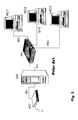
Figure 1 shows several networks as clouds, namely an ATM cloud 1, a local area
network (LAN) cloud 2, an Internet cloud 3, and a virtual private network (VPN)
cloud 4. The Internet cloud 3 is connected with the ATM cloud 1 as well as the VPN
cloud 4 is connected with the ATM cloud 1 via access servers AS. The LAN cloud 2
connects a host HO with a customer premises equipment CPE, e.g. a digital
subscriber line (DSL) modem. The customer premises equipment CPE is connected
with an digital subscriber line access multiplexer DSLAM, which itself is connected
(or a part) of the ATM cloud 1.
The configuration enables a host HO to reach networks like the Internet cloud 3 or
the VPN cloud 4. Via the LAN cloud the host HO is enabled to reach the customer
premises equipment CPE, e.g. a DSL modem. The customer premises equipment
CPE could connect via a line to the DSL access multiplexer DSLAM. The DSL access
multiplexer DSLAM could continue the connection through the ATM cloud reaching
finally a network access server AS (to reach the Internet or the VPN networks 3, 4).
A customer premises equipment CPE might be a telephone or other service
provider equipment that is located on the customer's premises (physical location)
rather than on the provider's premises or in between. Telephones, modems,
integrated services digital network adapters, cable TV adapters, and Digital
Subscriber Line routers are examples. Such devices at the customer's physical
location are called access network elements.
Figure 2 shows the network elements of the LAN cloud 2 in detail. There are
several hosts HO1, H02, and HO3, a hub HU, a gateway GW and a modem
MO. The hosts HO1, HO2, and HO3, are connected via Ethernet cables EN1,
EN2, and EN3 with the hub HU. The hub HU is also connected with a gateway
GW via an Ethernet connection EN; and the gateway GW is connected via an
Ethernet connection EN with the modem MO. The modem MO terminates the line
LI, also called local loop. The hosts HO1, HO2, and HO3 on the LAN share a
single modem (connection).
Figure 3 shows single connections between hosts HO and network access servers
AS via customer premises equipment CPR and DSL access multiplexer DSLAM etc.
Ethernet connections between multiple host HO and one (shared) customer
premises equipment CPE allow exchanging packets via a single ATM connection,
i.e. a permanent virtual path (PVC) to the DSL access multiplexer DSLAM and set
forth reaching the corresponding network access server AS through an ATM
network.
That means the hosts sharing a customer premises equipment share a single ATM
connection (PVC). Hence, the different packet streams will interfere with each
other.
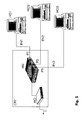
Figure 4 illustrates the basic idea behind the invention that the data streams are
discriminated and each stream has a private permanent virtual circuit ALs per
Ethernet link ELs. The innovation is that an enhanced customer premises
equipment CPE', i.e. the access network element in general, continues the Ethernet
links (packet streams) ELs by parallel permanent virtual circuits ALs. Especially for
each of the hosts HO1, HO2, and HO3, each having an Ethernet link Els to a
enhanced customer premises equipment CPE1 the Ethernet links are each
continued by (parallel) permanent virtual cicuits ALs to an access multiplexer
DSLAM1 and further to an access server AS1 through a ATM network.
Figure 5 shows an example local area network configuration with the enhanced
customer premises equipment CPE'. The enhanced customer premises equipment
CPE' comprises a modem connected with a hub HU. The hub HU comprises three
prots P1, P2, and P3. The modem is linked with a not shown access multiplexer via
a local loop connection LI. Eack of the shown three hosts HO1, HO2, and HO3 is
connected via an Ethernet link to one of the ports P1, P2, and P3.
With this configuration the host on the Ethernet LAN sharing the (xDSL) modem,
can have their own ATM connection. The modem will forward Ethernet packets
coming in on an Ethernet port into a dedicated (set of) ATM connections based on
the source MAC address, found e.g. in the Ethernet packet header.
Ethernet devices HO1, HO2, or HO3, ... on the LAN connected to (one of) the
Ethernet port(s) P1, P2, or P3 of the modem MO are sending out Ethernet packets
with a unique source MAC address. The modem MO (and network behind it)
supports multiple ATM connections which can be allocated to the Ethernet packet
stream from a specific MAC address and/or a specific Ethernet port, as illustrated
by the enhanced customer premises equipment CPE' comprising a modem MO
and a built in hub HU.
The enhanced customer premises equipment CPE' might host a table in witch each
source MAC address/Ethernet port is mapped onto a set of ATM connections.
Whenever an Ethernet packet comes in on a specific Ethernet port, the Ethernet
packet is forwarded into the corresponding ATM connection (based on the table).
Ethernet packets are sent out towards network with network access server MAC
address as destination and the host (terminal) MAC address as source. In the
backward path, the network access server sends out Ethernet packets with the
terminal MAC Address as destination and the network access server MAC address
as source.
Claims (7)
- A method for accessing a network access server (AS, AS1) in a multiple terminal access network including a local area network (2) and an asynchronous transfer mode network (1), said local area network (2) connecting multiple terminal devices (HO, HO1, HO2, HO3) via an access network element (CPE, CPE', CPE1 ) with said asynchronous transfer mode network (1) comprising the network access server, characterized in that said local area network (2) is an Ethernet and in that exchanging Ethernet packet(s) between one terminal device of said multiple terminal devices (HO, HO1, HO2, H03) and said network access server (AS, AS1) by transmitting Ethernet packet(s) over a defined separate asynchronous transfer mode connection (ALs) which is identified by a media access control address.
- The method according to claim 1, characterized in that additional media access control addresses identify additional multiple asynchronous transfer mode connections (ALs) between said one terminal device and said network access server.
- An access network element (CPE, CPE', CPEI) being connected with multiple terminal devices (HO, HO1, HO2, H03) via a local area network, said access network element (CPE, CPE', CPE1) is further connected with a network access server (AS, AS1) via an asynchronous transfer mode network (1), characterized in that said local area network (2) is an Ethernet, and in that said access network element (CPE, CPE', CPE1) comprising interface means for supporting multiple asynchronous transfer mode connections (ALs) which are identified by media access control addresses.
- An access network element (CPE, CPE', CPE1) according to claim 3, characterized in that the access network element (CPE, CPE', CPE1) is a modem.
- An access network element (CPE, CPE', CPE1) according to claim 4, characterized in that the modem is combined with a hub where a port of the hub is identified by a media access control address.
- A network access server (AS, AS1) being connected with an access network element (CPE, CPE', CPE1) via an asynchronous transfer mode network (1), said access network element (CPE, CPE', CPE1) is connected with multiple terminal devices (HO, HO1, HO2, HO3) via a local area network, characterized in that said local area network (2) is an Ethernet, and in that said network access server (AS, AS1) comprising interface means for supporting multiple asynchronous transfer mode connections (ALs) which are identified by media access control addresses.
- A computer software product for accessing a network access server (AS, AS1) in a multiple terminal access network including a local area network (2) and an asynchronous transfer mode network (1), said local area network (2) connecting multiple terminal devices (HO, HO1, HO2, HO3) via an access network element (CPE, CPE', CPE1) with said asynchronous transfer mode network (1) comprising the network access server, characterized in that said local area network (2) is an Ethernet and in that the computer software product comprising programming means for exchanging Ethernet packet(s) between one terminal device of said multiple terminal devices (HO, HO1, HO2, HO3) and said network access server (AS, AS1) by transmitting Ethernet packet(s) over a defined separate asynchronous transfer mode connection (ALs) which are identified by media access control address.
Priority Applications (1)
| Application Number | Priority Date | Filing Date | Title |
|---|---|---|---|
| EP03291154A EP1480392A1 (en) | 2003-05-19 | 2003-05-19 | A method, an access network element, a network access server, and a computer software product for accessing a network |
Applications Claiming Priority (1)
| Application Number | Priority Date | Filing Date | Title |
|---|---|---|---|
| EP03291154A EP1480392A1 (en) | 2003-05-19 | 2003-05-19 | A method, an access network element, a network access server, and a computer software product for accessing a network |
Publications (1)
| Publication Number | Publication Date |
|---|---|
| EP1480392A1 true EP1480392A1 (en) | 2004-11-24 |
Family
ID=33041109
Family Applications (1)
| Application Number | Title | Priority Date | Filing Date |
|---|---|---|---|
| EP03291154A Withdrawn EP1480392A1 (en) | 2003-05-19 | 2003-05-19 | A method, an access network element, a network access server, and a computer software product for accessing a network |
Country Status (1)
| Country | Link |
|---|---|
| EP (1) | EP1480392A1 (en) |
Citations (5)
| Publication number | Priority date | Publication date | Assignee | Title |
|---|---|---|---|---|
| EP0836306A1 (en) * | 1996-10-10 | 1998-04-15 | Hewlett-Packard Company | System providing for multiple virtual circuits between two network entities |
| US5946313A (en) * | 1997-03-20 | 1999-08-31 | Northern Telecom Limited | Mechanism for multiplexing ATM AAL5 virtual circuits over ethernet |
| US6424657B1 (en) * | 2000-08-10 | 2002-07-23 | Verizon Communications Inc. | Traffic queueing for remote terminal DSLAMs |
| US20030035471A1 (en) * | 2000-05-31 | 2003-02-20 | George Pitsoulakis | Modem having flexible architecture for connecting to multiple channel interfaces |
| US20030081614A1 (en) * | 2001-10-31 | 2003-05-01 | Kiyoshi Sukegawa | Digital subscriber line communication method and apparatus |
-
2003
- 2003-05-19 EP EP03291154A patent/EP1480392A1/en not_active Withdrawn
Patent Citations (5)
| Publication number | Priority date | Publication date | Assignee | Title |
|---|---|---|---|---|
| EP0836306A1 (en) * | 1996-10-10 | 1998-04-15 | Hewlett-Packard Company | System providing for multiple virtual circuits between two network entities |
| US5946313A (en) * | 1997-03-20 | 1999-08-31 | Northern Telecom Limited | Mechanism for multiplexing ATM AAL5 virtual circuits over ethernet |
| US20030035471A1 (en) * | 2000-05-31 | 2003-02-20 | George Pitsoulakis | Modem having flexible architecture for connecting to multiple channel interfaces |
| US6424657B1 (en) * | 2000-08-10 | 2002-07-23 | Verizon Communications Inc. | Traffic queueing for remote terminal DSLAMs |
| US20030081614A1 (en) * | 2001-10-31 | 2003-05-01 | Kiyoshi Sukegawa | Digital subscriber line communication method and apparatus |
Similar Documents
| Publication | Publication Date | Title |
|---|---|---|
| US7835370B2 (en) | System and method for DSL subscriber identification over ethernet network | |
| US8036237B2 (en) | System and method for transparent virtual routing | |
| US9088619B2 (en) | Quality of service based on logical port identifier for broadband aggregation networks | |
| US7808979B2 (en) | Methods and systems for packet aggregation combining connection-oriented and connection-less techniques | |
| US8451833B2 (en) | System and method for transparent virtual routing | |
| US20020019875A1 (en) | Service selection in a shared access network | |
| US20100287287A1 (en) | Network Apparatus and Method for Translating Media Access Control Addresses | |
| EP1542425B1 (en) | Method for autoconfiguring CPEs in DSL networks | |
| Cisco | Glossary | |
| Cisco | ADSL Technology Glossary | |
| Cisco | Appendix E: ADSL Technology Glossary | |
| Cisco | Appendix G: ADSL Technology Glossary | |
| Cisco | ADSL Technology Glossary | |
| Cisco | Appendix F: ADSL Technology Glossary | |
| Cisco | Appendix B: ADSL Technology Glossary | |
| Cisco | Glossary | |
| Cisco | Glossary | |
| Cisco | Appendix A: ADSL Technology Glossary | |
| Cisco | Glossary | |
| Cisco | Appendix D: ADSL Technology Glossary | |
| Cisco | Appendix D: ADSL Technology Glossary | |
| EP1480392A1 (en) | A method, an access network element, a network access server, and a computer software product for accessing a network | |
| Cisco | Glossary | |
| Cisco | Appendix F: ADSL Technology Glossary | |
| Cisco | Appendix E: ADSL Technology Glossary |
Legal Events
| Date | Code | Title | Description |
|---|---|---|---|
| PUAI | Public reference made under article 153(3) epc to a published international application that has entered the european phase |
Free format text: ORIGINAL CODE: 0009012 |
|
| AK | Designated contracting states |
Kind code of ref document: A1 Designated state(s): AT BE BG CH CY CZ DE DK EE ES FI FR GB GR HU IE IT LI LU MC NL PT RO SE SI SK TR |
|
| AX | Request for extension of the european patent |
Extension state: AL LT LV MK |
|
| AKX | Designation fees paid | ||
| REG | Reference to a national code |
Ref country code: DE Ref legal event code: 8566 |
|
| STAA | Information on the status of an ep patent application or granted ep patent |
Free format text: STATUS: THE APPLICATION IS DEEMED TO BE WITHDRAWN |
|
| 18D | Application deemed to be withdrawn |
Effective date: 20050525 |