EP1477203A2 - Epicard-Elektrode - Google Patents
Epicard-Elektrode Download PDFInfo
- Publication number
- EP1477203A2 EP1477203A2 EP20040090173 EP04090173A EP1477203A2 EP 1477203 A2 EP1477203 A2 EP 1477203A2 EP 20040090173 EP20040090173 EP 20040090173 EP 04090173 A EP04090173 A EP 04090173A EP 1477203 A2 EP1477203 A2 EP 1477203A2
- Authority
- EP
- European Patent Office
- Prior art keywords
- electrode
- claw
- epicardial
- heart tissue
- stimulation
- Prior art date
- Legal status (The legal status is an assumption and is not a legal conclusion. Google has not performed a legal analysis and makes no representation as to the accuracy of the status listed.)
- Granted
Links
Images


Classifications
-
- A—HUMAN NECESSITIES
- A61—MEDICAL OR VETERINARY SCIENCE; HYGIENE
- A61N—ELECTROTHERAPY; MAGNETOTHERAPY; RADIATION THERAPY; ULTRASOUND THERAPY
- A61N1/00—Electrotherapy; Circuits therefor
- A61N1/02—Details
- A61N1/04—Electrodes
- A61N1/05—Electrodes for implantation or insertion into the body, e.g. heart electrode
- A61N1/0587—Epicardial electrode systems; Endocardial electrodes piercing the pericardium
Definitions
- the present invention relates to an epicardial electrode, that is to say one on the outside of the heart muscle to be attached, for a cardiac stimulation device such as a defibrillator or a pacemaker.
- the supply of electrical signals as stimulation signals is a long-used medical therapy.
- pacemakers but also implantable defibrillators in a patient's chest used by means of an internal energy source, for example a battery, if necessary generate electrical signals.
- an electrode line the end facing away from the pacemaker (one speaks in this context an electrode is also arranged from the distal end of the electrode line), a specific part of the heart, depending on the medical application fed.
- the electrode can be a unipolar electrode or a bipolar one Electrode.
- a unipolar electrode is an electrode with a single pole, the so-called different pole, which emits the stimulation pulses.
- the unipolar Electrode is assigned a reference electrode with a so-called indifferent pole.
- the Reference electrode which is also referred to as an indifferent electrode, is often used by a patch electrode arranged on the outer skin of the heart muscle (epicardium) or formed by the housing of the stimulation device. On the outside of the heart muscle attached electrodes also become epicardial or epicardial electrodes Called electrodes.
- a bipolar electrode In contrast to the unipolar electrode, a bipolar electrode has both differen as well as an indifferent pole, so that no further electrode is needed.
- an electrode inside the Heart fixed in the area of the apex. There is a passage of the electrode lead through the ventricles or through the coronary sinus.
- One near the The apex of the right ventricle is shown, for example, in US Pat. No. 5,683,447. Placement of the electrode is through the ventricles or the coronary sinus however not harmless.
- the first object is achieved by an epicardium electrode according to claim 1 second task through an introducer according to claim 13.
- the dependent Claims define advantageous configurations of the epicardial electrode or the Introducer.
- An epicardial electrode according to the invention which is particularly suitable for use with a cardiac stimulation device is suitable, comprises an electrode body, one for Attachment to the heart tissue and to stimulate a part of the heart, d. H. one Partial area of the heart, trained stimulation area and at least one Has fixing element for fixing the stimulation surface on the heart tissue.
- the at least one fixing element is designed to engage in the heart tissue.
- the epicardial electrode according to the invention can be on the outside and in particular to be attached to the outer skin of the heart muscle (epicardium) without like a patch electrode to be sutured to the heart muscle. It only needs the fixing element be brought into engagement with the heart tissue.
- the electrode according to the invention facilitates access to the heart and, in particular, allows the electrode in a minimally invasive procedure.
- Electrode according to the invention can be used, for example.
- the electrode according to the invention therefore facilitates this in particular for Significant stimulation of the heart rhythm and / or for sensing heart signals Access to the left heart apex.
- the at least one fixing element can be used to fix the stimulation surface without To enable suturing, in particular in the form of an insertable into the heart tissue Claw be designed.
- the claw is designed so that it can move for fixing the electrode body to the heart tissue from one into the electrode body retracted condition for engaging the heart tissue is to be extended.
- the claw can then be inserted into the electrode during insertion Be drawn into the body of the electrode so as not to impede the insertion. Only when the electrode has reached its target position in the body does the claw become extended to fix the stimulation surface.
- This is particularly advantageous Design when the claw in the retracted position in the electrode body is completely arranged inside the electrode body.
- the Electrode body for receiving the claw a channel with an elongated, for Stimulation surface parallel channel section and such a curved Channel section that the channel has an outlet opening in the stimulation surface.
- at least part of the claw is designed to be flexible and in the channel arranged that it is essentially in the retracted state of the claw elongated in the elongated channel section and in the extended state in the curved Channel section is located.
- at least a part of the claw mounts in the retracted position State parallel to the stimulation surface.
- the parallel course of the claw part in the retracted Condition allows the claw to be fully drawn into the electrode body and at the same time to keep the height of the electrode body relatively flat. This is particularly important if the dimensions of the electrode are small should be kept to implant in a minimally invasive procedure facilitate.
- the claw can in particular also be used to intervene in the heart tissue provided stiff claw portion which is arcuate and which is in the retracted state in the curved channel section.
- the stiffness the curved claw section acts to bend the claw during manufacture against the intervention with the heart tissue.
- the electrode according to the invention advantageously comprises several Claws.
- two mutually opposite claw pairs can be present his.
- each fixing element Engagement element associated with a releasable engagement of one for actuating the Fixing element designed actuating element allows.
- an engagement element for example an eyelet
- a plurality of fixing elements d. H.
- each fixing element also have its own engaging element.
- the electrode can then with the Actuating element can be positioned in engagement in the engagement element on the heart.
- the fixing element is then engaged with the aid of the actuating element brought to the heart tissue. After the heart tissue procedure is established, the engagement of the actuating element in the engagement element is released. The The actuator can then be removed.
- the engagement element enables this Extending a claw by moving the actuating element essentially parallel relative to the stimulation area, especially if the Electrode body an elongated channel section for receiving the claw having.
- this has on the stimulation surface a different pole.
- the different pole can be connected to a reservoir anti-inflammatory agent, such as a steroid, to be equipped Inflammation arises from the intervention of the fixation element in the heart tissue to inhibit.
- the part to be stimulated can be stimulated by means of the different pole the appropriate stimulation signals are supplied to the heart.
- the different pole also enables the heart to sense electrical signals For example, can be used to trigger or trigger the stimulation.
- the stimulation surface can also be a medical one Tissue, such as Dacron, to adhere to the heart tissue. This enables a particularly secure fixation of the stimulation surface to the heart tissue.
- an introducer is also used for minimally invasive insertion provided electrode in the body, the one Actuating mechanism with an actuating element for actuating the at least one fixing element such that the engagement of the fixing element with the heart tissue is produced.
- the introducer sets with it Application tool that, in addition to placing the electrode, also for Making the procedure can be used.
- the operating mechanism can in particular be designed such that it extends at least one claw from the electrode body.
- the actuation mechanism in one embodiment of the introducer formed that he a substantially parallel displacement of the actuating element relative to the stimulation area. Moving the actuator then leads to a parallel also relative to the stimulation surface Moving the engaging element connected to the claw, which in turn increases extending the claw out of the electrode body.
- the introducer can also be used with holding clips to hold the implantable Electrode when inserting the implantable electrode into the body his.
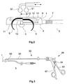
- Figures 1 and 2 show a schematic representation of a bipolar epicardial electrode for a cardiac stimulation device as a first embodiment for the epicardial electrode according to the invention.
- Fig. 1 shows the electrode in supervision, while Fig. 2 shows the electrode in a vertical section.
- the electrode comprises an electrode body 1, for example made of silicone, which is arranged at the distal end of an electrode line 3 and the underside of which Forms stimulation surface 4 of the epicardial electrode with a different pole 5.
- the stimulation signals to the heart.
- the Different pole 5 via an electrical line running through the electrode line 3 6 connected to the stimulation device.
- the indifferent pole 7 is in the embodiment shown as an annular electrode surface on the electrode line 3 arranged.
- the electrode shown in FIGS. 1 and 2 is a bipolar electrode formed, but it can also be designed as a unipolar electrode. In this In this case, there is no indifferent pole 7 on the electrode line. Instead serves then z. B. the housing of the stimulation device or a patch electrode as indifferent pole.
- the epicardial electrode according to the invention comprises four claws 9 as fixing elements (two of which can be seen in Fig. 2), which are opposite one another in pairs are arranged in channels 11 of the electrode body 1.
- the claws 9 can be move along these channels 11 between two end positions, the claws in the one end position, which is shown in Fig. 2, from the electrode body are extended so that their claw tips protrude beyond the stimulation surface 4.
- Eyes 13 are arranged at the end of the claws 9 opposite the claw tips, the sections of the channels running parallel to the stimulation surface are located and the engagement of balls 51, 52 of an introducer 50, which as Actuating elements for actuating the claws allow. Every pair of claws a common eyelet is assigned.
- the claws 9 By moving the balls 51, 52 against one another parallel to the stimulation surface 4 the claws 9 can be retracted and extended. In particular, they can be made from one State in which they are completely within the channels 11, in the extended Bring condition. The condition in which the claws are completely inside the Channels are arranged is by the corresponding end position shown in dashed lines the eyelets 13 'indicated. If the stimulation surface 4 on the heart muscle is present, the claws 9 penetrate into the heart tissue as they extend and anchor them in this way the electrode.
- an additional fixation of the epicardium electrode on the Heart tissue allows is a medical on the underside of the stimulation surface 4 Dacron fabric 14 arranged (not shown in Fig. 2), the one Allows the electrode to adhere to the heart tissue.
- pole 5 is equipped with a steroid reservoir his. The steroid is used to reduce inflammation that occurs when the claws are inserted inhibit the heart tissue.
- the electrode does include fixing elements four claws 9, which lie opposite one another in pairs in the electrode body 1 are arranged, however, any number of fixing elements can be used come.
- the number of fixing elements can, for example, depend on the size the stimulation area or the degree of fixation desired.
- FIG. 3 shows schematically an embodiment for the introducer 50 for Introducing the epicardial electrode according to the invention into the body.
- the Introducer 50 includes a hollow tube 54, one at its distal end Engagement in the eyelets 13 of the claws 9 configured ball 51 is fixed.
- a rod 56 which is in relation to the hollow tube 54 in Can be moved longitudinally.
- a second one designed to engage in the eyelets 13 of the claws 52.
- a handle 58 with two handle parts 60, 62 arranged.
- the two handle parts 60, 62 can be pivoted in this way via a joint 64 arranged to each other and connected to the rod 56 or the tube 54 that itself the balls 51, 52 move towards each other when the two handle parts 60, 62 towards each other to be pivoted, and the two balls 51, 52 away from each other move when the two handle parts 60, 62 are pivoted away from each other.
- the Balls 51, 52, tube 54, rod 56 and handle 58 together form one Actuating mechanism for retracting and extending the claws 9.
- the introducer 50 also serves for placement the electrode, which, for example, by means of the balls 51, 52 on the insertion device 50 is held. Once the electrode is placed in the right place on the heart, it can be attached using the operating mechanism. After this Extending the claws 9, the introducer 50 is removed again.
- the top of the Electrode body 1 two extending in the direction of displacement of the eyelets 13 Have slots or elongated holes, where the eyes 13 in the extended State of the claws 9 are so widened that the balls 51, 52 only on this point, i.e. when the claws are extended, through the slots or Slots can pass through.
- the Balls 51, 52 are inserted into the eyelets 13 when the claws are extended, and then the claws are retracted by actuating the actuating mechanism. there the balls 51, 52 get into those sections of the slots or elongated holes that do not allow balls 51, 52 to pass through. Only after extending the The balls 51, 52 can be clawed, i.e. after the electrode has been fixed pull out of the eyelets 13.
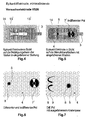
- FIGs 4 to 7 show a second embodiment of the invention Epicardium electrode
- FIG. 4 a view of the electrode body 1
- FIG. 5 show a view of the stimulation surface 4.
- Figure 6 shows an enlarged Representation of a section of the stimulation surface 4, the different and includes indifferent pole 5 or 7 'of the epicardial electrode. 7 is the stimulation area 4 in one showing the different pole 5 and the extended claws 9 shown enlarged view.
- Features of the second embodiment, the do not differ from those of the first embodiment, are with the same reference numerals as in the first embodiment.
- the second embodiment differs from the first only in that the indifferent pole 7 ′ does not form an annular electrode surface on the electrode line 3 is arranged, but just like the different pole 5 on the stimulation surface 4. This allows good contact between the indifferent pole 7 'and the Achieve heart tissue.
- arranging the indifferent increases Electrode 7 'on the stimulation surface 4 because of the distance between the indifferent and the different pole can be approximately 10 mm or more.
- the electrode body 1 is approximately 4.6 mm high, approximately 10 mm wide and approx. 25 mm long.
- the area of the arranged on the stimulation area Dacron fabric is approx. 14 mm x 32 mm.
- the claws 9 can be made of wire, for example, and typically have a diameter of about 0.2 mm.
- the channels for the claws 9 in the electrode body 1 then typically have a diameter of approximately 0.4 mm.
- the differente and the indifferent pole typically have a diameter of approx. 1.8 mm or 4.0 mm, the thickness of the different pole approximately 0.6 mm and that of the indifferent pole is approximately 0.3 mm.
- a steroid reservoir is located in the center of the different pole 8 with a diameter of approx. 1.0 mm, which contains approx. 1 mg of a steroid, e.g. Dexamethasone phosphate.
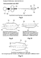
- Figure 8 shows a second embodiment of the invention Introducer.
- the introducer 50 'according to the second embodiment corresponds in principle to that of the first embodiment.
- Features of the introducer according to the second embodiment, which differ from do not differ from those of the first embodiment are in both embodiments with the same reference numerals.
- the second embodiment includes the handle 68 of the actuator to each other Move the balls not two swiveling handle parts but instead two mutually displaceable handle parts 70, 72.
- the introducer also includes 50 'of the second exemplary embodiment, two holding clips 74, 76 for holding the electrode during the insertion and fixing process.
- the retaining clips 74, 76 can optionally in a device provided on the handle 68 in a closed position, in which they have an electrode at the distal end of the introducer hold, or in an open position in which the electrode is not held become.
- Figures 9 and 10 show the distal end of the introducer 50 'in the Configuration that it with extended claws of the electrode and with closed Holding clips 74, 75 has.
- Figure 11 shows the distal end of the introducer however, with the claws retracted and the holding clips 74, 76 open.
- the introducer 50 ' is in accordance with the second exemplary embodiment with closed retaining clips 74, 76 and from retaining clips 74, 76 epicardial electrode shown.
- To hold the epicardial electrode securely to be supported by the retaining clips 74, 76 are in the side walls of the Electrode body 1 grooves 16 into which the retaining clips 74, 76 in intervene closed state.
- 12 to 14 the electrode and the distal end of the introducer 50 'from different angles extended claws 9 and closed retaining clips 74, 76 show the FIGS. 15 and 16 show the electrode and the distal end of the insertion set 50 ' retracted claws 9 and closed retaining clips 74, 76.
- the actuators instead of as balls simple pins suitable for engaging in the eyelets 13 of the claws 9 of the electrode to train because the actuators do not have a holding function for the electrode need.
Abstract
Description
- Figur 1
- zeigt in Aufsicht schematisch ein erstes Ausführungsbeispiel für die erfindungsgemäße Epikard-Elektrode.
- Figur 2
- zeigt schematisch das erste Ausführungsbeispiel für die erfindungsgemäße Epikard-Elektrode in einem vertikalen Schnitt.
- Figur 3
- zeigt schematisch ein erstes Ausführungsbeispiel für das Einführbesteck zum Einführen der erfindungsgemäßen Epikard-Elektrode.
- Figur 4
- zeigt die Oberseite eines zweiten Ausführungsbeispiels für die erfindungsgemäße Epikard-Elektrode.
- Figur 5
- zeigt die Unterseite des zweiten Ausführungsbeispiels für die erfindungsgemäße Epikard-Elektrode.
- Figuren 6 u. 7
- zeigen Details der Unterseite des zweiten Ausführungsbeispiels für die erfindungsgemäße Epikard-Elektrode.
- Figur 8
- zeigt in einer Gesamtansicht ein zweites Ausführungsbeispiel für das Einführbesteck für die erfindungsgemäße Epikard-Elektrode.
- Figuren 9 - 11
- zeigen das zweite Ausführungsbeispiel für das erfindungsgemäße Einführbesteck in verschiedenen Stellungen.
- Figuren 12 - 16
- zeigen das zweite Ausführungsbeispiel für das erfindungsgemäße Einführbesteck mit daran angeordneter Epikard-Elektrode in verschiedenen Stellungen.
Claims (16)
- Epikard-Elektrode für ein Herzstimulationsgerät, mit einem Elektrodenkörper (1), der eine zur Anlage an das Herzgewebe und zur Stimulation einer Partie des Herzens ausgebildete Stimulationsfläche (4) und mindestens ein zum Eingriff in das Herzgewebe ausgestaltetes Fixierelement (9) zum Fixieren der Stimulationsfläche (4) am Herzgewebe aufweist.
- Epikard-Elektrode nach Anspruch 1, bei der das mindestens eine Fixierelement in Form einer in das Herzgewebe einbringbaren Kralle (9) ausgestaltet ist.
- Epikard-Elektrode nach Anspruch 2, bei der die Kralle (9) derart beweglich ausgestaltet ist, dass sie zum Herstellen eines Eingriffs mit dem Herzgewebe aus einem in den Elektrodenköper (1) eingezogenen Zustand auszufahren ist.
- Epikard-Elektrode nach Anspruch 3, bei der die Kralle (9) in der in den Elektrodenkörper (1) eingezogenen Position vollständig im Inneren des Elektrodenkörpers (1) angeordnet ist.
- Epikard-Elektrode nach Anspruch 4, bei der der Elektrodenkörper (1) mindestens einen Kanal (11) mit einem langgestreckten, zur Stimulationsfläche (4) parallel verlaufenden Kanalabschnitt und einem derart gekrümmten Kanalabschnitt, dass der Kanal (11) eine Austrittsöffnung in der Stimulationsfläche (4) aufweist, umfasst, und bei der mindestens ein Teil der Kralle (9) derart flexibel ausgebildet und im Kanal (11) angeordnet ist, dass er sich im eingezogenen Zustand der Kralle (9) im Wesentlichen langgestreckt im langgestreckten Kanalabschnitt und im ausgefahrenen Zustand der Kralle (9) im gekrümmten Kanalabschnitt befindet.
- Epikard-Elektrode nach Anspruch 5, bei der die Kralle (9) einen zum Eingriff in das Herzgewebe vorgesehenen steifen Krallenabschnitt aufweist, der bogenförmig ausgebildet ist und der sich im eingezogenen Zustand im gekrümmten Kanalabschnitt befindet.
- Epikard-Elektrode nach einem der Ansprüche 1 bis 6, bei der mehrere Krallen (9) vorhanden sind.
- Epikard-Elektrode nach einem der Ansprüche 1 bis 7, bei der jedem Fixierelement (9) ein Eingriffselement (13) zugeordnet ist, das einen lösbaren Eingriff eines zum Betätigen des Fixierelementes (9) ausgestalteten Betätigungselementes (51, 52) ermöglicht.
- Epikard-Elektrode nach Anspruch 5 und Anspruch 8, bei der sich das Eingriffselement (13) zum Ausfahren der Kralle (9) durch das Betätigungselement (51, 52) im Wesentlichen parallel zur Stimulationsfläche (4) verschieben lässt.
- Epikard-Elektrode nach einem der vorangehenden Ansprüche, die an der Stimulationsfläche (4) einen differenten Pol (5) aufweist.
- Epikard-Elektrode nach Anspruch 10, bei welcher der differente Pol (5) mit einem Reservoir (8) eines entzündungshemmenden Wirkstoffes ausgestattet ist.
- Epikard-Elektrode nach einem der vorangehenden Ansprüche, bei der die Stimulationsfläche (4) ein medizinisches Gewebe (14) zum Festwachsen mit dem Herzgewebe umfasst.
- Einführbesteck zum minimalinvasiven Einführen einer Elektrode nach einem der Ansprüche 1 bis 12 in den Körper, welches einen Betätigungsmechanismus (51 - 58) mit mindestens einem Betätigungselement (51, 52) zum Betätigen des mindestens einen Fixierelementes (9) derart, dass der Eingriff des Fixierelementes (9) in das Herzgewebe erfolgt, aufweist.
- Einführbesteck nach Anspruch 13 zum Einführen einer Epikard-Elektrode nach Anspruch 3, bei welcher der Betätigungsmechanismus (51 - 58) derart ausgestaltet ist, dass er ein Ausfahren der Kralle (9) aus dem Elektrodenkörper (1) ermöglicht.
- Einführbesteck nach Anspruch 14 zum Einführen einer Epikard-Elektrode nach Anspruch 9, bei welcher der Betätigungsmechanismus (51 - 58) zum im Wesentlichen parallelen Verschieben des Betätigungselementes (51, 52) relativ zur Stimulationsfläche (4) ausgebildet ist.
- Einführbesteck nach einem der Ansprüche 13 bis 15, bei dem Halteklammern (74, 76) zum Halten der Epikard-Elektrode beim Einführen in den Körper vorhanden sind.
Applications Claiming Priority (2)
| Application Number | Priority Date | Filing Date | Title |
|---|---|---|---|
| DE10323016 | 2003-05-15 | ||
| DE10323016A DE10323016A1 (de) | 2003-05-15 | 2003-05-15 | Epicard-Elektrode |
Publications (3)
| Publication Number | Publication Date |
|---|---|
| EP1477203A2 true EP1477203A2 (de) | 2004-11-17 |
| EP1477203A3 EP1477203A3 (de) | 2005-03-16 |
| EP1477203B1 EP1477203B1 (de) | 2015-09-02 |
Family
ID=33016448
Family Applications (1)
| Application Number | Title | Priority Date | Filing Date |
|---|---|---|---|
| EP04090173.8A Expired - Fee Related EP1477203B1 (de) | 2003-05-15 | 2004-05-05 | Epicard-Elektrode |
Country Status (3)
| Country | Link |
|---|---|
| US (1) | US7085606B2 (de) |
| EP (1) | EP1477203B1 (de) |
| DE (1) | DE10323016A1 (de) |
Cited By (3)
| Publication number | Priority date | Publication date | Assignee | Title |
|---|---|---|---|---|
| US11103280B2 (en) | 2012-12-10 | 2021-08-31 | Nevro Corp. | Lead insertion devices and associated systems and methods |
| US11389647B2 (en) | 2020-02-03 | 2022-07-19 | Nevro Corp. | Neurological stimulation lead anchors and associated tools, and methods |
| US11420045B2 (en) | 2018-03-29 | 2022-08-23 | Nevro Corp. | Leads having sidewall openings, and associated systems and methods |
Families Citing this family (118)
| Publication number | Priority date | Publication date | Assignee | Title |
|---|---|---|---|---|
| US8068920B2 (en) * | 2006-10-03 | 2011-11-29 | Vincent A Gaudiani | Transcoronary sinus pacing system, LV summit pacing, early mitral closure pacing, and methods therefor |
| US10166066B2 (en) | 2007-03-13 | 2019-01-01 | University Of Virginia Patent Foundation | Epicardial ablation catheter and method of use |
| US9468396B2 (en) | 2007-03-19 | 2016-10-18 | University Of Virginia Patent Foundation | Systems and methods for determining location of an access needle in a subject |
| US11058354B2 (en) | 2007-03-19 | 2021-07-13 | University Of Virginia Patent Foundation | Access needle with direct visualization and related methods |
| WO2011103456A2 (en) | 2010-02-18 | 2011-08-25 | University Of Virginia Patent Foundation | System, method, and computer program product for simulating epicardial electrophysiology procedures |
| CA2680639C (en) | 2007-03-19 | 2017-03-07 | University Of Virginia Patent Foundation | Access needle pressure sensor device and method of use |
| US9211405B2 (en) | 2007-03-22 | 2015-12-15 | University Of Virginia Patent Foundation | Electrode catheter for ablation purposes and related method thereof |
| EP2170458A1 (de) * | 2007-06-13 | 2010-04-07 | E- Pacing, Inc. | Implantierbare produkte und verfahren zur stimulation von herz- oder anderem gewebe |
| US20100241185A1 (en) | 2007-11-09 | 2010-09-23 | University Of Virginia Patent Foundation | Steerable epicardial pacing catheter system placed via the subxiphoid process |
| US8594809B2 (en) * | 2008-04-25 | 2013-11-26 | Medtronic, Inc. | Passive fixation medical electrical lead |
| US8195297B2 (en) * | 2008-10-13 | 2012-06-05 | E-Pacing, Inc. | Devices and methods for electrical stimulation of the diaphragm and nerves |
| US9642534B2 (en) | 2009-09-11 | 2017-05-09 | University Of Virginia Patent Foundation | Systems and methods for determining location of an access needle in a subject |
| US20110218604A1 (en) * | 2010-03-02 | 2011-09-08 | Sen Ji | Cardiac Lead for Epicardial, Endocardial and Trans-Coronary Sinus Placement |
| US10071243B2 (en) | 2013-07-31 | 2018-09-11 | Medtronic, Inc. | Fixation for implantable medical devices |
| US10722723B2 (en) | 2013-08-16 | 2020-07-28 | Cardiac Pacemakers, Inc. | Delivery devices and methods for leadless cardiac devices |
| US10842993B2 (en) | 2013-08-16 | 2020-11-24 | Cardiac Pacemakers, Inc. | Leadless cardiac pacing devices |
| US9492674B2 (en) | 2013-08-16 | 2016-11-15 | Cardiac Pacemakers, Inc. | Leadless cardiac pacemaker with delivery and/or retrieval features |
| US9480850B2 (en) | 2013-08-16 | 2016-11-01 | Cardiac Pacemakers, Inc. | Leadless cardiac pacemaker and retrieval device |
| AU2014306940B2 (en) | 2013-08-16 | 2017-09-07 | Cardiac Pacemakers, Inc. | Leadless cardiac pacing devices |
| US9393427B2 (en) | 2013-08-16 | 2016-07-19 | Cardiac Pacemakers, Inc. | Leadless cardiac pacemaker with delivery and/or retrieval features |
| EP3338856B1 (de) | 2013-08-16 | 2021-08-04 | Cardiac Pacemakers, Inc. | Abgabevorrichtungen für elektrodenlose herzvorrichtungen |
| US9700732B2 (en) | 2013-08-16 | 2017-07-11 | Cardiac Pacemakers, Inc. | Leadless cardiac pacemaker and retrieval device |
| AU2015204701B2 (en) | 2014-01-10 | 2018-03-15 | Cardiac Pacemakers, Inc. | Systems and methods for detecting cardiac arrhythmias |
| WO2015106007A1 (en) | 2014-01-10 | 2015-07-16 | Cardiac Pacemakers, Inc. | Methods and systems for improved communication between medical devices |
| US10080887B2 (en) | 2014-04-29 | 2018-09-25 | Cardiac Pacemakers, Inc. | Leadless cardiac pacing devices including tissue engagement verification |
| EP3137163B1 (de) | 2014-04-29 | 2019-02-20 | Cardiac Pacemakers, Inc. | Elektrodenloser herzschrittmacher mit rückholvorrichtung |
| WO2016033197A2 (en) | 2014-08-28 | 2016-03-03 | Cardiac Pacemakers, Inc. | Medical device with triggered blanking period |
| WO2016126613A1 (en) | 2015-02-06 | 2016-08-11 | Cardiac Pacemakers, Inc. | Systems and methods for treating cardiac arrhythmias |
| US10220213B2 (en) | 2015-02-06 | 2019-03-05 | Cardiac Pacemakers, Inc. | Systems and methods for safe delivery of electrical stimulation therapy |
| WO2016130477A2 (en) | 2015-02-09 | 2016-08-18 | Cardiac Pacemakers, Inc. | Implantable medical device with radiopaque id tag |
| WO2016141046A1 (en) | 2015-03-04 | 2016-09-09 | Cardiac Pacemakers, Inc. | Systems and methods for treating cardiac arrhythmias |
| CN107427222B (zh) | 2015-03-18 | 2021-02-09 | 心脏起搏器股份公司 | 使用链路质量评估的医疗设备系统中的通信 |
| US10050700B2 (en) | 2015-03-18 | 2018-08-14 | Cardiac Pacemakers, Inc. | Communications in a medical device system with temporal optimization |
| CN108136186B (zh) | 2015-08-20 | 2021-09-17 | 心脏起搏器股份公司 | 用于医疗装置之间的通信的系统和方法 |
| EP3337559B1 (de) | 2015-08-20 | 2019-10-16 | Cardiac Pacemakers, Inc. | Systeme und verfahren zur kommunikation zwischen medizinischen vorrichtungen |
| US9956414B2 (en) | 2015-08-27 | 2018-05-01 | Cardiac Pacemakers, Inc. | Temporal configuration of a motion sensor in an implantable medical device |
| US9968787B2 (en) | 2015-08-27 | 2018-05-15 | Cardiac Pacemakers, Inc. | Spatial configuration of a motion sensor in an implantable medical device |
| US10226631B2 (en) | 2015-08-28 | 2019-03-12 | Cardiac Pacemakers, Inc. | Systems and methods for infarct detection |
| WO2017040115A1 (en) | 2015-08-28 | 2017-03-09 | Cardiac Pacemakers, Inc. | System for detecting tamponade |
| WO2017040153A1 (en) | 2015-08-28 | 2017-03-09 | Cardiac Pacemakers, Inc. | Systems and methods for behaviorally responsive signal detection and therapy delivery |
| WO2017044389A1 (en) | 2015-09-11 | 2017-03-16 | Cardiac Pacemakers, Inc. | Arrhythmia detection and confirmation |
| CN108136185B (zh) | 2015-10-08 | 2021-08-31 | 心脏起搏器股份公司 | 用于调整可植入医疗装置中的起搏速率的装置和方法 |
| WO2017091812A1 (en) | 2015-11-25 | 2017-06-01 | Talon Medical, LLC | Tissue engagement devices, systems, and methods |
| WO2017106693A1 (en) | 2015-12-17 | 2017-06-22 | Cardiac Pacemakers, Inc. | Conducted communication in a medical device system |
| US10905886B2 (en) | 2015-12-28 | 2021-02-02 | Cardiac Pacemakers, Inc. | Implantable medical device for deployment across the atrioventricular septum |
| WO2017127548A1 (en) | 2016-01-19 | 2017-07-27 | Cardiac Pacemakers, Inc. | Devices for wirelessly recharging a rechargeable battery of an implantable medical device |
| US10463853B2 (en) | 2016-01-21 | 2019-11-05 | Medtronic, Inc. | Interventional medical systems |
| US10099050B2 (en) | 2016-01-21 | 2018-10-16 | Medtronic, Inc. | Interventional medical devices, device systems, and fixation components thereof |
| US10350423B2 (en) | 2016-02-04 | 2019-07-16 | Cardiac Pacemakers, Inc. | Delivery system with force sensor for leadless cardiac device |
| US11116988B2 (en) | 2016-03-31 | 2021-09-14 | Cardiac Pacemakers, Inc. | Implantable medical device with rechargeable battery |
| US10328272B2 (en) | 2016-05-10 | 2019-06-25 | Cardiac Pacemakers, Inc. | Retrievability for implantable medical devices |
| US10668294B2 (en) | 2016-05-10 | 2020-06-02 | Cardiac Pacemakers, Inc. | Leadless cardiac pacemaker configured for over the wire delivery |
| WO2018005373A1 (en) | 2016-06-27 | 2018-01-04 | Cardiac Pacemakers, Inc. | Cardiac therapy system using subcutaneously sensed p-waves for resynchronization pacing management |
| US11207527B2 (en) | 2016-07-06 | 2021-12-28 | Cardiac Pacemakers, Inc. | Method and system for determining an atrial contraction timing fiducial in a leadless cardiac pacemaker system |
| US10426962B2 (en) | 2016-07-07 | 2019-10-01 | Cardiac Pacemakers, Inc. | Leadless pacemaker using pressure measurements for pacing capture verification |
| US10688304B2 (en) | 2016-07-20 | 2020-06-23 | Cardiac Pacemakers, Inc. | Method and system for utilizing an atrial contraction timing fiducial in a leadless cardiac pacemaker system |
| WO2018035343A1 (en) | 2016-08-19 | 2018-02-22 | Cardiac Pacemakers, Inc. | Trans septal implantable medical device |
| CN109641129B (zh) | 2016-08-24 | 2023-06-30 | 心脏起搏器股份公司 | 使用融合促进进行定时管理的心脏再同步 |
| WO2018039335A1 (en) | 2016-08-24 | 2018-03-01 | Cardiac Pacemakers, Inc. | Integrated multi-device cardiac resynchronization therapy using p-wave to pace timing |
| WO2018057318A1 (en) | 2016-09-21 | 2018-03-29 | Cardiac Pacemakers, Inc. | Leadless stimulation device with a housing that houses internal components of the leadless stimulation device and functions as the battery case and a terminal of an internal battery |
| US10994145B2 (en) | 2016-09-21 | 2021-05-04 | Cardiac Pacemakers, Inc. | Implantable cardiac monitor |
| US10758737B2 (en) | 2016-09-21 | 2020-09-01 | Cardiac Pacemakers, Inc. | Using sensor data from an intracardially implanted medical device to influence operation of an extracardially implantable cardioverter |
| US10238865B2 (en) | 2016-10-06 | 2019-03-26 | Medtronic, Inc. | Electrode fixation in interventional medical systems |
| EP3532159B1 (de) | 2016-10-27 | 2021-12-22 | Cardiac Pacemakers, Inc. | System zur einführung einer implantierbaren medizinischen vorrichtung mit integriertem sensor |
| WO2018081275A1 (en) | 2016-10-27 | 2018-05-03 | Cardiac Pacemakers, Inc. | Multi-device cardiac resynchronization therapy with timing enhancements |
| AU2017350759B2 (en) | 2016-10-27 | 2019-10-17 | Cardiac Pacemakers, Inc. | Implantable medical device with pressure sensor |
| US10328257B2 (en) | 2016-10-27 | 2019-06-25 | Medtronic, Inc. | Electrode fixation in interventional medical systems |
| WO2018081237A1 (en) | 2016-10-27 | 2018-05-03 | Cardiac Pacemakers, Inc. | Use of a separate device in managing the pace pulse energy of a cardiac pacemaker |
| US10561330B2 (en) | 2016-10-27 | 2020-02-18 | Cardiac Pacemakers, Inc. | Implantable medical device having a sense channel with performance adjustment |
| US10413733B2 (en) | 2016-10-27 | 2019-09-17 | Cardiac Pacemakers, Inc. | Implantable medical device with gyroscope |
| US10434317B2 (en) | 2016-10-31 | 2019-10-08 | Cardiac Pacemakers, Inc. | Systems and methods for activity level pacing |
| CN109890456B (zh) | 2016-10-31 | 2023-06-13 | 心脏起搏器股份公司 | 用于活动水平起搏的系统 |
| WO2018089311A1 (en) | 2016-11-08 | 2018-05-17 | Cardiac Pacemakers, Inc | Implantable medical device for atrial deployment |
| CN109952129B (zh) | 2016-11-09 | 2024-02-20 | 心脏起搏器股份公司 | 为心脏起搏设备设定心脏起搏脉冲参数的系统、设备和方法 |
| US10894163B2 (en) | 2016-11-21 | 2021-01-19 | Cardiac Pacemakers, Inc. | LCP based predictive timing for cardiac resynchronization |
| US10881869B2 (en) | 2016-11-21 | 2021-01-05 | Cardiac Pacemakers, Inc. | Wireless re-charge of an implantable medical device |
| US10639486B2 (en) | 2016-11-21 | 2020-05-05 | Cardiac Pacemakers, Inc. | Implantable medical device with recharge coil |
| JP6843240B2 (ja) | 2016-11-21 | 2021-03-17 | カーディアック ペースメイカーズ, インコーポレイテッド | 透磁性ハウジング及びハウジングの周りに配置された誘導コイルを備える植込み型医療装置 |
| EP3541473B1 (de) | 2016-11-21 | 2020-11-11 | Cardiac Pacemakers, Inc. | Elektrodenloser herzschrittmacher mit multimodaler kommunikation |
| US11207532B2 (en) | 2017-01-04 | 2021-12-28 | Cardiac Pacemakers, Inc. | Dynamic sensing updates using postural input in a multiple device cardiac rhythm management system |
| EP3573709A1 (de) | 2017-01-26 | 2019-12-04 | Cardiac Pacemakers, Inc. | Elektrodenlose vorrichtung mit umspritzten bauteilen |
| CN110198759B (zh) | 2017-01-26 | 2023-08-11 | 心脏起搏器股份公司 | 具有可拆卸固定件的无引线可植入装置 |
| WO2018140617A1 (en) | 2017-01-26 | 2018-08-02 | Cardiac Pacemakers, Inc. | Intra-body device communication with redundant message transmission |
| AU2018248361B2 (en) | 2017-04-03 | 2020-08-27 | Cardiac Pacemakers, Inc. | Cardiac pacemaker with pacing pulse energy adjustment based on sensed heart rate |
| US10905872B2 (en) | 2017-04-03 | 2021-02-02 | Cardiac Pacemakers, Inc. | Implantable medical device with a movable electrode biased toward an extended position |
| US11065459B2 (en) | 2017-08-18 | 2021-07-20 | Cardiac Pacemakers, Inc. | Implantable medical device with pressure sensor |
| US10918875B2 (en) | 2017-08-18 | 2021-02-16 | Cardiac Pacemakers, Inc. | Implantable medical device with a flux concentrator and a receiving coil disposed about the flux concentrator |
| CN111107899B (zh) | 2017-09-20 | 2024-04-02 | 心脏起搏器股份公司 | 具有多种操作模式的可植入医疗装置 |
| US11185703B2 (en) | 2017-11-07 | 2021-11-30 | Cardiac Pacemakers, Inc. | Leadless cardiac pacemaker for bundle of his pacing |
| EP3717060B1 (de) | 2017-12-01 | 2022-10-05 | Cardiac Pacemakers, Inc. | Leitungsloser herzschritzmascher mit reversionärem verhalten |
| EP3717059A1 (de) | 2017-12-01 | 2020-10-07 | Cardiac Pacemakers, Inc. | Verfahren und systeme zur erkennung von referenzpunkten für die vorhofkontraktionszeit innerhalb eines suchfensters von einem ventrikulär implantierten leitungslosen herzschrittmacher |
| EP3717064B1 (de) | 2017-12-01 | 2023-06-07 | Cardiac Pacemakers, Inc. | Verfahren und systeme zur erfassung von atrialen kontraktionstaktmarkern während einer ventrikelfüllung aus einem ventrikulär implantierten leitungslosen herzschrittmacher |
| US11071870B2 (en) | 2017-12-01 | 2021-07-27 | Cardiac Pacemakers, Inc. | Methods and systems for detecting atrial contraction timing fiducials and determining a cardiac interval from a ventricularly implanted leadless cardiac pacemaker |
| US11529523B2 (en) | 2018-01-04 | 2022-12-20 | Cardiac Pacemakers, Inc. | Handheld bridge device for providing a communication bridge between an implanted medical device and a smartphone |
| EP3735293B1 (de) | 2018-01-04 | 2022-03-09 | Cardiac Pacemakers, Inc. | Zweikammer-stimulation ohne schlag-zu-schlag-kommunikation |
| CN111902187A (zh) | 2018-03-23 | 2020-11-06 | 美敦力公司 | Vfa心脏再同步治疗 |
| EP3768160B1 (de) | 2018-03-23 | 2023-06-07 | Medtronic, Inc. | Vfa-herztherapie für tachykardie |
| EP3768369A1 (de) | 2018-03-23 | 2021-01-27 | Medtronic, Inc. | Av-synchrone vfa-herztherapie |
| US10576291B2 (en) | 2018-07-31 | 2020-03-03 | Manicka Institute Llc | Subcutaneous device |
| US11660444B2 (en) | 2018-07-31 | 2023-05-30 | Manicka Institute Llc | Resilient body component contact for a subcutaneous device |
| US11717674B2 (en) | 2018-07-31 | 2023-08-08 | Manicka Institute Llc | Subcutaneous device for use with remote device |
| US11433233B2 (en) | 2020-11-25 | 2022-09-06 | Calyan Technologies, Inc. | Electrode contact for a subcutaneous device |
| US10716511B2 (en) | 2018-07-31 | 2020-07-21 | Manicka Institute Llc | Subcutaneous device for monitoring and/or providing therapies |
| US11179571B2 (en) | 2018-07-31 | 2021-11-23 | Manicka Institute Llc | Subcutaneous device for monitoring and/or providing therapies |
| US11235161B2 (en) | 2018-09-26 | 2022-02-01 | Medtronic, Inc. | Capture in ventricle-from-atrium cardiac therapy |
| US11648397B1 (en) | 2018-10-12 | 2023-05-16 | Vincent Gaudiani | Transcoronary sinus pacing of posteroseptal left ventricular base |
| US11577075B1 (en) | 2018-10-12 | 2023-02-14 | Vincent A. Gaudiani | Transcoronary sinus pacing of his bundle |
| US11951313B2 (en) | 2018-11-17 | 2024-04-09 | Medtronic, Inc. | VFA delivery systems and methods |
| US11679265B2 (en) | 2019-02-14 | 2023-06-20 | Medtronic, Inc. | Lead-in-lead systems and methods for cardiac therapy |
| US11759632B2 (en) | 2019-03-28 | 2023-09-19 | Medtronic, Inc. | Fixation components for implantable medical devices |
| US11697025B2 (en) | 2019-03-29 | 2023-07-11 | Medtronic, Inc. | Cardiac conduction system capture |
| US11213676B2 (en) | 2019-04-01 | 2022-01-04 | Medtronic, Inc. | Delivery systems for VfA cardiac therapy |
| US11712188B2 (en) | 2019-05-07 | 2023-08-01 | Medtronic, Inc. | Posterior left bundle branch engagement |
| US11305127B2 (en) | 2019-08-26 | 2022-04-19 | Medtronic Inc. | VfA delivery and implant region detection |
| US11813466B2 (en) | 2020-01-27 | 2023-11-14 | Medtronic, Inc. | Atrioventricular nodal stimulation |
| US11911168B2 (en) | 2020-04-03 | 2024-02-27 | Medtronic, Inc. | Cardiac conduction system therapy benefit determination |
| US11813464B2 (en) | 2020-07-31 | 2023-11-14 | Medtronic, Inc. | Cardiac conduction system evaluation |
| US10987060B1 (en) | 2020-09-14 | 2021-04-27 | Calyan Technologies, Inc. | Clip design for a subcutaneous device |
Citations (1)
| Publication number | Priority date | Publication date | Assignee | Title |
|---|---|---|---|---|
| US5683447A (en) | 1995-12-19 | 1997-11-04 | Ventritex, Inc. | Lead with septal defibrillation and pacing electrodes |
Family Cites Families (16)
| Publication number | Priority date | Publication date | Assignee | Title |
|---|---|---|---|---|
| US4144890A (en) * | 1975-01-14 | 1979-03-20 | Cordis Corporation | Contact device for muscle stimulation |
| US3999555A (en) * | 1975-10-28 | 1976-12-28 | Medtronic, Inc. | Atrial pinch on lead and insertion tool |
| US4142530A (en) * | 1978-03-06 | 1979-03-06 | Vitatron Medical B. V. | Epicardial lead |
| US4235246A (en) * | 1979-02-05 | 1980-11-25 | Arco Medical Products Company | Epicardial heart lead and assembly and method for optimal fixation of same for cardiac pacing |
| US4282886A (en) * | 1979-11-13 | 1981-08-11 | Medtronic, Inc. | Adhesive bonded positive fixation epicardial lead |
| US4357946A (en) * | 1980-03-24 | 1982-11-09 | Medtronic, Inc. | Epicardial pacing lead with stylet controlled helical fixation screw |
| US4424818A (en) * | 1982-02-18 | 1984-01-10 | Medtronic, Inc. | Electrical lead and insertion tool |
| EP0134367A1 (de) * | 1983-08-12 | 1985-03-20 | Jean-Pierre Alfandari | Herzschrittmachervorrichtung mit einer sich von Befestigungsmitteln unterscheidenden epikardischen Elektrode |
| USH356H (en) * | 1985-02-27 | 1987-11-03 | Medtronic, Inc. | Epicardial lead having low threshold, low polarization myocardial electrode |
| US4607644A (en) * | 1985-04-01 | 1986-08-26 | Cordis Corporation | Self-suturing porous epicardial electrode assembly |
| US5314462A (en) * | 1992-05-27 | 1994-05-24 | Cardiac Pacemakers, Inc. | Positive fixation device |
| US5304203A (en) * | 1992-10-20 | 1994-04-19 | Numed Technologies, Inc. | Tissue extracting forceps for laparoscopic surgery |
| US5545207A (en) * | 1994-08-24 | 1996-08-13 | Medtronic, Inc. | Medical electrical lead having stable fixation system |
| US5630831A (en) * | 1995-05-04 | 1997-05-20 | Lahr; Christopher J. | Fingerlike medical instruments for use in laparoscopic procedures |
| US5871532A (en) * | 1997-05-22 | 1999-02-16 | Sulzer Intermedics Inc. | Epicardial lead for minimally invasive implantation |
| SE0201320D0 (sv) * | 2002-04-30 | 2002-04-30 | St Jude Medical | Epicardial pacing lead arrangement |
-
2003
- 2003-05-15 DE DE10323016A patent/DE10323016A1/de not_active Withdrawn
-
2004
- 2004-05-05 EP EP04090173.8A patent/EP1477203B1/de not_active Expired - Fee Related
- 2004-05-14 US US10/845,686 patent/US7085606B2/en active Active
Patent Citations (1)
| Publication number | Priority date | Publication date | Assignee | Title |
|---|---|---|---|---|
| US5683447A (en) | 1995-12-19 | 1997-11-04 | Ventritex, Inc. | Lead with septal defibrillation and pacing electrodes |
Cited By (3)
| Publication number | Priority date | Publication date | Assignee | Title |
|---|---|---|---|---|
| US11103280B2 (en) | 2012-12-10 | 2021-08-31 | Nevro Corp. | Lead insertion devices and associated systems and methods |
| US11420045B2 (en) | 2018-03-29 | 2022-08-23 | Nevro Corp. | Leads having sidewall openings, and associated systems and methods |
| US11389647B2 (en) | 2020-02-03 | 2022-07-19 | Nevro Corp. | Neurological stimulation lead anchors and associated tools, and methods |
Also Published As
| Publication number | Publication date |
|---|---|
| US7085606B2 (en) | 2006-08-01 |
| EP1477203A3 (de) | 2005-03-16 |
| DE10323016A1 (de) | 2004-12-02 |
| EP1477203B1 (de) | 2015-09-02 |
| US20040267343A1 (en) | 2004-12-30 |
Similar Documents
| Publication | Publication Date | Title |
|---|---|---|
| EP1477203B1 (de) | Epicard-Elektrode | |
| DE69628663T2 (de) | Minimalinvasive, medizinische, elektrische leitung | |
| DE2506694C2 (de) | Implantierbare, transvenös einführbare Elektrodenanordnung | |
| DE60311487T2 (de) | Zuführsystem für medizinische vorrichtungen | |
| DE4335098B4 (de) | Elektrodenzuleitung mit Halteelement für einen Führungsstab und deren Verwendung | |
| DE69826546T2 (de) | Medizinische elektrische Leitung | |
| EP0951920B1 (de) | Gefässelektrodenleitung | |
| DE69833361T2 (de) | Medizinische elektrische Zuleitung | |
| DE602004005845T2 (de) | Drehbarer leitungseinführer | |
| DE2643956A1 (de) | Elektrodensystem zur behandlung des herzkammerflatterns und verfahren zu seiner anwendung | |
| EP2123323B1 (de) | Implantierbare Elektrodenleitung | |
| EP2589348B1 (de) | Vorrichtung zur Explantation von Elektrodenleitungen | |
| DE60013893T2 (de) | System und elektrode zur perkutanen elektrischen therapie | |
| DE60114291T2 (de) | Vorrichtung zum Implantieren von einer Herzstimulationsleitung in Koronargefässen | |
| DE2743431A1 (de) | Verfahren und vorrichtung zur einpflanzung einer oder mehrerer schrittmacher-elektroden in ein herz | |
| DE10034097A1 (de) | System zum Bereitstellen medizinischer, elektrischer Stimulation an Nervengewebe | |
| DE202010017584U1 (de) | Gastrointestinale Vorrichtung | |
| DE102015223541A1 (de) | Implantierbares Fluidpumpensystem | |
| EP2767306B1 (de) | Chirurgisches Applikationswerkzeug zur Implantation eines Elektrodendrahts | |
| EP2143464A2 (de) | Implantierbare Elektrodenleitung oder Elektrodenleitungsanordnung | |
| EP2184082A1 (de) | Implantierbare Leitung | |
| EP2281600B1 (de) | Vorrichtung zur Defibrillation eines Herzens | |
| EP2001406A1 (de) | Vorrichtung zur reversiblen befestigung eines implantats im auge | |
| AT512534A4 (de) | Nerven-Cuff-Elektrodenanordnung | |
| WO2019110550A1 (de) | Implantat mit reservoir |
Legal Events
| Date | Code | Title | Description |
|---|---|---|---|
| PUAI | Public reference made under article 153(3) epc to a published international application that has entered the european phase |
Free format text: ORIGINAL CODE: 0009012 |
|
| AK | Designated contracting states |
Kind code of ref document: A2 Designated state(s): AT BE BG CH CY CZ DE DK EE ES FI FR GB GR HU IE IT LI LU MC NL PL PT RO SE SI SK TR |
|
| AX | Request for extension of the european patent |
Extension state: AL HR LT LV MK |
|
| PUAL | Search report despatched |
Free format text: ORIGINAL CODE: 0009013 |
|
| AK | Designated contracting states |
Kind code of ref document: A3 Designated state(s): AT BE BG CH CY CZ DE DK EE ES FI FR GB GR HU IE IT LI LU MC NL PL PT RO SE SI SK TR |
|
| AX | Request for extension of the european patent |
Extension state: AL HR LT LV MK |
|
| 17P | Request for examination filed |
Effective date: 20050916 |
|
| AKX | Designation fees paid |
Designated state(s): AT BE BG CH CY CZ DE DK EE ES FI FR GB GR HU IE IT LI LU MC NL PL PT RO SE SI SK TR |
|
| RAP1 | Party data changed (applicant data changed or rights of an application transferred) |
Owner name: BIOTRONIK SE & CO. KG |
|
| RAP1 | Party data changed (applicant data changed or rights of an application transferred) |
Owner name: BIOTRONIK SE & CO. KG |
|
| GRAP | Despatch of communication of intention to grant a patent |
Free format text: ORIGINAL CODE: EPIDOSNIGR1 |
|
| INTG | Intention to grant announced |
Effective date: 20150528 |
|
| GRAS | Grant fee paid |
Free format text: ORIGINAL CODE: EPIDOSNIGR3 |
|
| GRAA | (expected) grant |
Free format text: ORIGINAL CODE: 0009210 |
|
| AK | Designated contracting states |
Kind code of ref document: B1 Designated state(s): AT BE BG CH CY CZ DE DK EE ES FI FR GB GR HU IE IT LI LU MC NL PL PT RO SE SI SK TR |
|
| REG | Reference to a national code |
Ref country code: GB Ref legal event code: FG4D Free format text: NOT ENGLISH |
|
| REG | Reference to a national code |
Ref country code: AT Ref legal event code: REF Ref document number: 746151 Country of ref document: AT Kind code of ref document: T Effective date: 20150915 Ref country code: CH Ref legal event code: EP |
|
| REG | Reference to a national code |
Ref country code: IE Ref legal event code: FG4D Free format text: LANGUAGE OF EP DOCUMENT: GERMAN |
|
| REG | Reference to a national code |
Ref country code: DE Ref legal event code: R096 Ref document number: 502004015012 Country of ref document: DE |
|
| PG25 | Lapsed in a contracting state [announced via postgrant information from national office to epo] |
Ref country code: GR Free format text: LAPSE BECAUSE OF FAILURE TO SUBMIT A TRANSLATION OF THE DESCRIPTION OR TO PAY THE FEE WITHIN THE PRESCRIBED TIME-LIMIT Effective date: 20151203 Ref country code: FI Free format text: LAPSE BECAUSE OF FAILURE TO SUBMIT A TRANSLATION OF THE DESCRIPTION OR TO PAY THE FEE WITHIN THE PRESCRIBED TIME-LIMIT Effective date: 20150902 |
|
| REG | Reference to a national code |
Ref country code: NL Ref legal event code: MP Effective date: 20150902 |
|
| PG25 | Lapsed in a contracting state [announced via postgrant information from national office to epo] |
Ref country code: ES Free format text: LAPSE BECAUSE OF FAILURE TO SUBMIT A TRANSLATION OF THE DESCRIPTION OR TO PAY THE FEE WITHIN THE PRESCRIBED TIME-LIMIT Effective date: 20150902 Ref country code: SE Free format text: LAPSE BECAUSE OF FAILURE TO SUBMIT A TRANSLATION OF THE DESCRIPTION OR TO PAY THE FEE WITHIN THE PRESCRIBED TIME-LIMIT Effective date: 20150902 Ref country code: PL Free format text: LAPSE BECAUSE OF FAILURE TO SUBMIT A TRANSLATION OF THE DESCRIPTION OR TO PAY THE FEE WITHIN THE PRESCRIBED TIME-LIMIT Effective date: 20150902 |
|
| PG25 | Lapsed in a contracting state [announced via postgrant information from national office to epo] |
Ref country code: NL Free format text: LAPSE BECAUSE OF FAILURE TO SUBMIT A TRANSLATION OF THE DESCRIPTION OR TO PAY THE FEE WITHIN THE PRESCRIBED TIME-LIMIT Effective date: 20150902 Ref country code: IT Free format text: LAPSE BECAUSE OF FAILURE TO SUBMIT A TRANSLATION OF THE DESCRIPTION OR TO PAY THE FEE WITHIN THE PRESCRIBED TIME-LIMIT Effective date: 20150902 Ref country code: CZ Free format text: LAPSE BECAUSE OF FAILURE TO SUBMIT A TRANSLATION OF THE DESCRIPTION OR TO PAY THE FEE WITHIN THE PRESCRIBED TIME-LIMIT Effective date: 20150902 Ref country code: SK Free format text: LAPSE BECAUSE OF FAILURE TO SUBMIT A TRANSLATION OF THE DESCRIPTION OR TO PAY THE FEE WITHIN THE PRESCRIBED TIME-LIMIT Effective date: 20150902 Ref country code: EE Free format text: LAPSE BECAUSE OF FAILURE TO SUBMIT A TRANSLATION OF THE DESCRIPTION OR TO PAY THE FEE WITHIN THE PRESCRIBED TIME-LIMIT Effective date: 20150902 |
|
| PG25 | Lapsed in a contracting state [announced via postgrant information from national office to epo] |
Ref country code: PT Free format text: LAPSE BECAUSE OF FAILURE TO SUBMIT A TRANSLATION OF THE DESCRIPTION OR TO PAY THE FEE WITHIN THE PRESCRIBED TIME-LIMIT Effective date: 20160104 Ref country code: RO Free format text: LAPSE BECAUSE OF FAILURE TO SUBMIT A TRANSLATION OF THE DESCRIPTION OR TO PAY THE FEE WITHIN THE PRESCRIBED TIME-LIMIT Effective date: 20150902 |
|
| REG | Reference to a national code |
Ref country code: DE Ref legal event code: R097 Ref document number: 502004015012 Country of ref document: DE |
|
| PLBE | No opposition filed within time limit |
Free format text: ORIGINAL CODE: 0009261 |
|
| STAA | Information on the status of an ep patent application or granted ep patent |
Free format text: STATUS: NO OPPOSITION FILED WITHIN TIME LIMIT |
|
| 26N | No opposition filed |
Effective date: 20160603 |
|
| PG25 | Lapsed in a contracting state [announced via postgrant information from national office to epo] |
Ref country code: DK Free format text: LAPSE BECAUSE OF FAILURE TO SUBMIT A TRANSLATION OF THE DESCRIPTION OR TO PAY THE FEE WITHIN THE PRESCRIBED TIME-LIMIT Effective date: 20150902 Ref country code: BE Free format text: LAPSE BECAUSE OF NON-PAYMENT OF DUE FEES Effective date: 20160531 Ref country code: SI Free format text: LAPSE BECAUSE OF FAILURE TO SUBMIT A TRANSLATION OF THE DESCRIPTION OR TO PAY THE FEE WITHIN THE PRESCRIBED TIME-LIMIT Effective date: 20150902 |
|
| PG25 | Lapsed in a contracting state [announced via postgrant information from national office to epo] |
Ref country code: LU Free format text: LAPSE BECAUSE OF FAILURE TO SUBMIT A TRANSLATION OF THE DESCRIPTION OR TO PAY THE FEE WITHIN THE PRESCRIBED TIME-LIMIT Effective date: 20160505 |
|
| GBPC | Gb: european patent ceased through non-payment of renewal fee |
Effective date: 20160505 |
|
| REG | Reference to a national code |
Ref country code: FR Ref legal event code: ST Effective date: 20170131 |
|
| PG25 | Lapsed in a contracting state [announced via postgrant information from national office to epo] |
Ref country code: FR Free format text: LAPSE BECAUSE OF NON-PAYMENT OF DUE FEES Effective date: 20160531 |
|
| PG25 | Lapsed in a contracting state [announced via postgrant information from national office to epo] |
Ref country code: GB Free format text: LAPSE BECAUSE OF NON-PAYMENT OF DUE FEES Effective date: 20160505 |
|
| REG | Reference to a national code |
Ref country code: AT Ref legal event code: MM01 Ref document number: 746151 Country of ref document: AT Kind code of ref document: T Effective date: 20160505 |
|
| PG25 | Lapsed in a contracting state [announced via postgrant information from national office to epo] |
Ref country code: AT Free format text: LAPSE BECAUSE OF NON-PAYMENT OF DUE FEES Effective date: 20160505 |
|
| PG25 | Lapsed in a contracting state [announced via postgrant information from national office to epo] |
Ref country code: CY Free format text: LAPSE BECAUSE OF FAILURE TO SUBMIT A TRANSLATION OF THE DESCRIPTION OR TO PAY THE FEE WITHIN THE PRESCRIBED TIME-LIMIT Effective date: 20150902 Ref country code: HU Free format text: LAPSE BECAUSE OF FAILURE TO SUBMIT A TRANSLATION OF THE DESCRIPTION OR TO PAY THE FEE WITHIN THE PRESCRIBED TIME-LIMIT; INVALID AB INITIO Effective date: 20040505 |
|
| PG25 | Lapsed in a contracting state [announced via postgrant information from national office to epo] |
Ref country code: TR Free format text: LAPSE BECAUSE OF FAILURE TO SUBMIT A TRANSLATION OF THE DESCRIPTION OR TO PAY THE FEE WITHIN THE PRESCRIBED TIME-LIMIT Effective date: 20150902 Ref country code: MC Free format text: LAPSE BECAUSE OF FAILURE TO SUBMIT A TRANSLATION OF THE DESCRIPTION OR TO PAY THE FEE WITHIN THE PRESCRIBED TIME-LIMIT Effective date: 20150902 |
|
| PG25 | Lapsed in a contracting state [announced via postgrant information from national office to epo] |
Ref country code: BG Free format text: LAPSE BECAUSE OF FAILURE TO SUBMIT A TRANSLATION OF THE DESCRIPTION OR TO PAY THE FEE WITHIN THE PRESCRIBED TIME-LIMIT Effective date: 20150902 |
|
| PGFP | Annual fee paid to national office [announced via postgrant information from national office to epo] |
Ref country code: DE Payment date: 20190529 Year of fee payment: 16 Ref country code: IE Payment date: 20190520 Year of fee payment: 16 |
|
| PGFP | Annual fee paid to national office [announced via postgrant information from national office to epo] |
Ref country code: CH Payment date: 20190523 Year of fee payment: 16 |
|
| REG | Reference to a national code |
Ref country code: DE Ref legal event code: R119 Ref document number: 502004015012 Country of ref document: DE |
|
| PG25 | Lapsed in a contracting state [announced via postgrant information from national office to epo] |
Ref country code: LI Free format text: LAPSE BECAUSE OF NON-PAYMENT OF DUE FEES Effective date: 20200531 Ref country code: CH Free format text: LAPSE BECAUSE OF NON-PAYMENT OF DUE FEES Effective date: 20200531 |
|
| PG25 | Lapsed in a contracting state [announced via postgrant information from national office to epo] |
Ref country code: IE Free format text: LAPSE BECAUSE OF NON-PAYMENT OF DUE FEES Effective date: 20200505 |
|
| PG25 | Lapsed in a contracting state [announced via postgrant information from national office to epo] |
Ref country code: DE Free format text: LAPSE BECAUSE OF NON-PAYMENT OF DUE FEES Effective date: 20201201 |