EP1460699A2 - Battery pack cooling system - Google Patents
Battery pack cooling system Download PDFInfo
- Publication number
- EP1460699A2 EP1460699A2 EP20040251480 EP04251480A EP1460699A2 EP 1460699 A2 EP1460699 A2 EP 1460699A2 EP 20040251480 EP20040251480 EP 20040251480 EP 04251480 A EP04251480 A EP 04251480A EP 1460699 A2 EP1460699 A2 EP 1460699A2
- Authority
- EP
- European Patent Office
- Prior art keywords
- battery pack
- rechargeable batteries
- fan
- cooling medium
- impeller
- Prior art date
- Legal status (The legal status is an assumption and is not a legal conclusion. Google has not performed a legal analysis and makes no representation as to the accuracy of the status listed.)
- Granted
Links
Images


Classifications
-
- H—ELECTRICITY
- H01—ELECTRIC ELEMENTS
- H01M—PROCESSES OR MEANS, e.g. BATTERIES, FOR THE DIRECT CONVERSION OF CHEMICAL ENERGY INTO ELECTRICAL ENERGY
- H01M10/00—Secondary cells; Manufacture thereof
- H01M10/60—Heating or cooling; Temperature control
- H01M10/61—Types of temperature control
- H01M10/613—Cooling or keeping cold
-
- H—ELECTRICITY
- H01—ELECTRIC ELEMENTS
- H01M—PROCESSES OR MEANS, e.g. BATTERIES, FOR THE DIRECT CONVERSION OF CHEMICAL ENERGY INTO ELECTRICAL ENERGY
- H01M10/00—Secondary cells; Manufacture thereof
- H01M10/60—Heating or cooling; Temperature control
- H01M10/61—Types of temperature control
- H01M10/617—Types of temperature control for achieving uniformity or desired distribution of temperature
-
- H—ELECTRICITY
- H01—ELECTRIC ELEMENTS
- H01M—PROCESSES OR MEANS, e.g. BATTERIES, FOR THE DIRECT CONVERSION OF CHEMICAL ENERGY INTO ELECTRICAL ENERGY
- H01M10/00—Secondary cells; Manufacture thereof
- H01M10/60—Heating or cooling; Temperature control
- H01M10/62—Heating or cooling; Temperature control specially adapted for specific applications
- H01M10/625—Vehicles
-
- H—ELECTRICITY
- H01—ELECTRIC ELEMENTS
- H01M—PROCESSES OR MEANS, e.g. BATTERIES, FOR THE DIRECT CONVERSION OF CHEMICAL ENERGY INTO ELECTRICAL ENERGY
- H01M10/00—Secondary cells; Manufacture thereof
- H01M10/60—Heating or cooling; Temperature control
- H01M10/64—Heating or cooling; Temperature control characterised by the shape of the cells
- H01M10/647—Prismatic or flat cells, e.g. pouch cells
-
- H—ELECTRICITY
- H01—ELECTRIC ELEMENTS
- H01M—PROCESSES OR MEANS, e.g. BATTERIES, FOR THE DIRECT CONVERSION OF CHEMICAL ENERGY INTO ELECTRICAL ENERGY
- H01M10/00—Secondary cells; Manufacture thereof
- H01M10/60—Heating or cooling; Temperature control
- H01M10/65—Means for temperature control structurally associated with the cells
- H01M10/651—Means for temperature control structurally associated with the cells characterised by parameters specified by a numeric value or mathematical formula, e.g. ratios, sizes or concentrations
-
- H—ELECTRICITY
- H01—ELECTRIC ELEMENTS
- H01M—PROCESSES OR MEANS, e.g. BATTERIES, FOR THE DIRECT CONVERSION OF CHEMICAL ENERGY INTO ELECTRICAL ENERGY
- H01M10/00—Secondary cells; Manufacture thereof
- H01M10/60—Heating or cooling; Temperature control
- H01M10/65—Means for temperature control structurally associated with the cells
- H01M10/655—Solid structures for heat exchange or heat conduction
- H01M10/6556—Solid parts with flow channel passages or pipes for heat exchange
- H01M10/6557—Solid parts with flow channel passages or pipes for heat exchange arranged between the cells
-
- H—ELECTRICITY
- H01—ELECTRIC ELEMENTS
- H01M—PROCESSES OR MEANS, e.g. BATTERIES, FOR THE DIRECT CONVERSION OF CHEMICAL ENERGY INTO ELECTRICAL ENERGY
- H01M10/00—Secondary cells; Manufacture thereof
- H01M10/60—Heating or cooling; Temperature control
- H01M10/65—Means for temperature control structurally associated with the cells
- H01M10/656—Means for temperature control structurally associated with the cells characterised by the type of heat-exchange fluid
- H01M10/6561—Gases
- H01M10/6563—Gases with forced flow, e.g. by blowers
-
- H—ELECTRICITY
- H01—ELECTRIC ELEMENTS
- H01M—PROCESSES OR MEANS, e.g. BATTERIES, FOR THE DIRECT CONVERSION OF CHEMICAL ENERGY INTO ELECTRICAL ENERGY
- H01M10/00—Secondary cells; Manufacture thereof
- H01M10/60—Heating or cooling; Temperature control
- H01M10/65—Means for temperature control structurally associated with the cells
- H01M10/656—Means for temperature control structurally associated with the cells characterised by the type of heat-exchange fluid
- H01M10/6561—Gases
- H01M10/6566—Means within the gas flow to guide the flow around one or more cells, e.g. manifolds, baffles or other barriers
-
- H—ELECTRICITY
- H01—ELECTRIC ELEMENTS
- H01M—PROCESSES OR MEANS, e.g. BATTERIES, FOR THE DIRECT CONVERSION OF CHEMICAL ENERGY INTO ELECTRICAL ENERGY
- H01M50/00—Constructional details or processes of manufacture of the non-active parts of electrochemical cells other than fuel cells, e.g. hybrid cells
- H01M50/20—Mountings; Secondary casings or frames; Racks, modules or packs; Suspension devices; Shock absorbers; Transport or carrying devices; Holders
- H01M50/204—Racks, modules or packs for multiple batteries or multiple cells
-
- H—ELECTRICITY
- H01—ELECTRIC ELEMENTS
- H01M—PROCESSES OR MEANS, e.g. BATTERIES, FOR THE DIRECT CONVERSION OF CHEMICAL ENERGY INTO ELECTRICAL ENERGY
- H01M6/00—Primary cells; Manufacture thereof
- H01M6/42—Grouping of primary cells into batteries
-
- Y—GENERAL TAGGING OF NEW TECHNOLOGICAL DEVELOPMENTS; GENERAL TAGGING OF CROSS-SECTIONAL TECHNOLOGIES SPANNING OVER SEVERAL SECTIONS OF THE IPC; TECHNICAL SUBJECTS COVERED BY FORMER USPC CROSS-REFERENCE ART COLLECTIONS [XRACs] AND DIGESTS
- Y02—TECHNOLOGIES OR APPLICATIONS FOR MITIGATION OR ADAPTATION AGAINST CLIMATE CHANGE
- Y02E—REDUCTION OF GREENHOUSE GAS [GHG] EMISSIONS, RELATED TO ENERGY GENERATION, TRANSMISSION OR DISTRIBUTION
- Y02E60/00—Enabling technologies; Technologies with a potential or indirect contribution to GHG emissions mitigation
- Y02E60/10—Energy storage using batteries
Definitions
- the present invention relates to a battery pack apparatus.
- a battery pack apparatus comprising a battery pack composed of a plurality of rechargeable batteries and a fan supplying a cooling medium through cooling medium passages between the rechargeable batteries to uniformly cool each of the rechargeable batteries.
- Apparatuses are known in the art wherein a supply space and a discharge space are disposed above and below a battery pack composed of a plurality of rechargeable batteries arranged in parallel and separated by cooling medium passages formed therebetween, and a cooling medium supply device is disposed to supply cooling medium from one end of the supply space (for example, see Japanese Patent Laid-Open Publication No. 2001-167803)
- a battery pack is formed as an integral unit from a plurality of rechargeable batteries in a rectangular shape inclined in a vertical direction in a containing case, and a fan is disposed beside a lower end portion of the battery pack to supply cooling air to a supply space at an upper portion of the battery pack, the air then passing through passages between the rechargeable batteries and through a discharge space at the lower end and finally discharging outside, thereby cooling each of the rechargeable batteries (for example, see Japanese Patent Laid-Open Publication No. 2001-167806)
- Apparatuses are also known wherein a plurality of rechargeable batteries are contained inside a case, and a fan having an impeller is disposed at one side of the case, the impeller having an axial length spanning substantially the entire length in the lengthwise direction of the case.
- cooling air is forcedly supplied by the fan to each of the rechargeable batteries (for example, see Japanese Patent Laid-Open Publication No. Hei 8-96858)
- An apparatus has also been conceived as shown in Figs. 6A and 6B.
- An inflow passage 24 for cooling medium is disposed at a lower portion of a battery pack 21 which has a plurality of rechargeable batteries 22 arranged in parallel and separated by cooling medium passages 23 formed therebetween.
- a discharge space 25 of a relatively large capacity is disposed at an upper portion of the battery pack 21.
- a discharge device 26 such as a sirocco fan is disposed at a substantially central portion of an upper surface of the discharge space 25.
- each of the cooling medium passages between the rechargeable batteries depending on which position in the supply space they communicate, a difference occurs in the circulation amount of the cooling medium, and temperature variations occur among the rechargeable batteries.
- a configuration was conceived wherein a cross flow fan 35 is disposed facing a discharge space 34 formed at an upper portion of a battery pack 31, the rotational axis of the fan following in the aligning direction of rechargeable batteries 32.
- a distance H between an upper edge of the battery pack 31 and the axis of the cross flow fan 35 as small as possible to facilitate a compact configuration in the vertical direction, variations occur in the flow amount of cooling medium in cooling medium passages 33 between the rechargeable batteries 32,32. That is, the flow rate distribution of cooling medium in the discharge space 34, as indicated by the length of the arrows in Fig.
- An object of the present invention is to provide a battery pack apparatus which is capable of uniformly cooling each of the rechargeable batteries of a battery pack within a compact configuration.
- a battery pack apparatus includes a battery pack composed of a plurality of rechargeable batteries arranged in parallel, the rechargeable batteries having cooling medium passages formed therebetween, and a cross flow fan disposed with an intake chamber facing a distribution space formed adjacent to one side face of the battery pack to supply or discharge cooling medium to each of the cooling medium passages, the fan having an impeller disposed such that a rotational axis thereof follows an aligning direction of the rechargeable batteries.
- An axial position of the fan is eccentric with respect to a center line of the distribution space, perpendicular to the aligning direction of the rechargeable batteries, in a direction of movement of the impeller at the distribution space side.
- the fan is disposed within proximity of one side face of the battery pack to configure the battery pack apparatus compactly, by disposing the cross flow fan with the axis thereof following the aligning direction of the rechargeable batteries, cooling medium is supplied equally to each of the cooling medium passages. Further, by the axial position of the fan being eccentric in the direction of movement of the impeller at the distribution space side, flow amount distribution of the cooling medium in each cooling medium passage is equalized, and each of the rechargeable batteries is cooled uniformly, and variations in SOC of the rechargeable batteries are suppressed to improve the battery life.
- the length of a stabilizer of the cross flow fan is from 1.5 to 5 times the size of a gap between an extremity of the stabilizer and the outer circumference of the impeller, and an intake chamber wall doubles as an air discharge passage wall or is adjacent to an air discharge passage wall, where the fan being disposed with the intake chamber facing the distribution space and the rotational axis is made to follow the aligning direction of the rechargeable batteries.
- the fan is disposed in proximity to one side face of the battery pack to configure the battery pack apparatus compactly, the capacity at the stabilizer area of the intake chamber is large, and therefore flow amount decline at an end portion, near the stabilizer, within each cooling medium passage is restrained, such that variations in flow amount distribution is decreased and pressure loss is further decreased.
- a battery pack apparatus 1 serves as a drive power source for an electric vehicle including hybrid vehicles, and contains a battery pack 5 composed of 10 to 30 flat prismatic rechargeable batteries 2 arranged in parallel with cooling medium passages 3 formed between the long side faces thereof, and being held between a pair of end plates 4 disposed at both ends in the aligning direction, and secured as an integral unit by a binding member (not shown)
- Each of the rechargeable batteries 2 is formed as a battery module including a plurality (6 in the shown example) of cells 2a arranged in the lengthwise direction of the long side faces, the cells 2a being internally connected in series, and external connection terminals 2b projected at both ends.
- the battery pack 5 obtains a predetermined output voltage by successively connecting the connection terminals 2b of the rechargeable batteries 2 in series by bus bars (not shown)
- Both ends of each of the rechargeable batteries 2 of the battery pack 5 are supported by support frames 6,6.
- a lower case 7 is disposed at a lower portion between the support frames 6,6.
- An inflow-end distribution space 8 is formed adjacent to a bottom side of the battery pack 5 by the lower case 7 to supply cooling medium to each of the cooling medium passages 3.
- the battery pack 5 is covered by an upper case 9 at an upper portion of the support frames 6,6.
- An outflow-end distribution space 10 is projectingly formed adjacent to a top side of the battery pack 5 by the upper case 9 to collect cooling medium which has flowed out from each of the cooling medium passages 3 and discharge it.
- a suction opening 10a for sucking cooling medium is formed on a top side of the outflow-end distribution space 10.
- a cross flow fan 11 is disposed on top of the upper case 9 with the axis thereof made to follow the aligning direction of the rechargeable batteries 2.
- An intake port ha of the fan 11 is joined to the suction opening 10a of the upper case 9.
- the fan 11 includes a substantially tubular impeller 13 of a diameter D accommodated in a fan case 12, and the impeller 13 is disposed to be freely rotatable, and is rotated by a motor 14 linked to an end of its axis.
- a stabilizer 15 is disposed at one side of the outer circumference of the impeller 13.
- a combined discharge passage/intake chamber wall 18 extends downward at an inclination from an end of the stabilizer 15 to join to a circumferential edge of the suction opening 10a of the upper case 9.
- An upper air discharge passage 16 and a lower intake chamber 17 are thus formed.
- An opening at one end of an air discharge duct 19 is joined to a discharge opening 12a of the fan case 12 and an outer edge of the combined discharge passage/intake chamber wall 18.
- the intake chamber 17 is formed by both a portion lower than the impeller 13 of the fan case 12 and the combined discharge passage/intake chamber wall 18, and a lower end opening thereof makes up the intake port 11a of the fan 11.
- the position of the axis 0 of the fan 11, with respect to a center line C of the outflow-end distribution space 10, the line in a perpendicular direction to the aligning direction of the rechargeable batteries, is eccentric by an amount x in the direction of movement of the impeller 13 of the fan 11 at the intake chamber 17 side.
- the eccentricity amount x, with respect to the impeller diameter D of the fan 11, is set to satisfy 0 ⁇ x ⁇ 1.0D, and preferably, 0.2D ⁇ x ⁇ 0.5D.
- D is 60 mm
- x is from 12 mm to 30 mm.
- a length s of the stabilizer 15 is from 1.5d to 5d, where d is a gap between the extremity of the stabilizer 15 and the outer circumference of the impeller 13.
- a length L in the aligning direction of the rechargeable batteries 2 of the battery pack 5 and a length F in the axial direction of the impeller 13 are set so as to satisfy F ⁇ L/2.
- the axis of the fan 11 is disposed to be perpendicular with respect to the cooling medium passages 3.
- the center of the impeller 13 in the axial direction is substantially matched with the center of the battery pack 5 in the aligning direction the rechargeable batteries.
- the fan 11 is configured so as to satisfy y ⁇ L/n where y is a displacement amount of the center of the impeller 13 with respect to the center of the battery pack 5 is such that, L is the same as before, and n is the number of the rechargeable batteries 2 of the battery pack 5. That is, the displacement amount y is not larger than a thickness of the rechargeable battery 2.
- the fan 11 is disposed such that the positions of junctures 13b in the axial direction of vanes 13a of the impeller 13 are offset from positions opposite to the cooling medium passages 3 between the rechargeable batteries 2,2.
- the battery pack apparatus 1 which is compact in the aligning direction of the rechargeable batteries 2 due to the fan 11 being disposed on the upper portion of the battery pack 5, is compactly configured in the vertical direction as well.
- the fan 11 is disposed in proximity to the top side of the battery pack 5, by disposing the cross flow fan 11 with the axis thereof following the aligning direction of the rechargeable batteries 2, cooling medium is equally supplied to each of the cooling medium passages 3 between the rechargeable batteries 2,2.
- the axial position of the fan 11 being eccentric in the direction of movement of the impeller 13 at the intake chamber 17 side, the flow amount distribution of the cooling medium within each of the cooling medium passages 3 is equalized without significantly decreasing the cooling medium flow amount.
- the length s of the stabilizer 15 of the fan 11 is set at from 1.5 to 5 times the gap d between the end of the stabilizer 15 and the outer circumference of the impeller 13, and the combined discharge passage/intake chamber wall 18 is extended from the end of the stabilizer 15, and thus the capacity of the intake chamber 17 is enlarged into the region indicated with the diagonal hypothetical lines in Fig. 1.
- the length F of the impeller 13 in the axial direction is set so as to satisfy F ⁇ L/2, with respect to the length L of the battery pack 5 in the aligning direction of the rechargeable batteries 2.
- the fan 11 is disposed such that the axis thereof is perpendicular with respect to the cooling medium passages 3, and thus pressure loss is decreased and flow amount is large. Cooling ability is thereby improved. Also, the fan 11 is disposed so as to satisfy y ⁇ L/n, where y is the displacement amount of the center of the impeller 13 in the axial direction with respect to the center of the battery pack 5 in the aligning direction of the rechargeable batteries, L is the length of the battery pack 5 in the aligning direction of the rechargeable batteries, and n is the number of the rechargeable batteries 2.
- the cooling medium is equally supplied to the cooling medium passages 3.
- the fan 11 is disposed such that positions of the junctures 13b in the axial direction of the vanes 13a of the impeller 13 are offset from positions opposite to the cooling medium passages 3, and thus flow rate of all of the cooling medium passages 3 is equalized without being effected by the junctures 13b of the vanes 13a.
- the battery pack apparatus 1 is configured compactly by the cross flow fan 11 being disposed adjacent to one side face of the battery pack 5, variations in SOC of the rechargeable batteries 2 is restrained so as to improve the battery life due to an ability to uniformly cool the rechargeable batteries 2.
- a battery pack apparatus of the present invention even though a fan is disposed in proximity to one side face of a battery pack, by disposing a cross flow fan such that the axis thereof follows the aligning direction of the rechargeable batteries, cooling medium is equally supplied to each of the cooling medium passages between the rechargeable batteries. Further, by the axial position of the fan being eccentric in the direction of movement of the impeller at a side of the one side face of the battery pack, flow amount distribution of the cooling medium within each of the cooling medium passages is equalized, and each of the rechargeable batteries are uniformly cooled within a compact configuration, and variations in SOC of the rechargeable batteries are restrained to improve the battery life.
Abstract
Description
- The present invention relates to a battery pack apparatus. In particular, it relates to a battery pack apparatus comprising a battery pack composed of a plurality of rechargeable batteries and a fan supplying a cooling medium through cooling medium passages between the rechargeable batteries to uniformly cool each of the rechargeable batteries.
- Apparatuses are known in the art wherein a supply space and a discharge space are disposed above and below a battery pack composed of a plurality of rechargeable batteries arranged in parallel and separated by cooling medium passages formed therebetween, and a cooling medium supply device is disposed to supply cooling medium from one end of the supply space (for example, see Japanese Patent Laid-Open Publication No. 2001-167803)
- Also, apparatuses are known wherein a battery pack is formed as an integral unit from a plurality of rechargeable batteries in a rectangular shape inclined in a vertical direction in a containing case, and a fan is disposed beside a lower end portion of the battery pack to supply cooling air to a supply space at an upper portion of the battery pack, the air then passing through passages between the rechargeable batteries and through a discharge space at the lower end and finally discharging outside, thereby cooling each of the rechargeable batteries (for example, see Japanese Patent Laid-Open Publication No. 2001-167806)
- Apparatuses are also known wherein a plurality of rechargeable batteries are contained inside a case, and a fan having an impeller is disposed at one side of the case, the impeller having an axial length spanning substantially the entire length in the lengthwise direction of the case. In this apparatus, cooling air is forcedly supplied by the fan to each of the rechargeable batteries (for example, see Japanese Patent Laid-Open Publication No. Hei 8-96858)
- An apparatus has also been conceived as shown in Figs. 6A and 6B. An
inflow passage 24 for cooling medium is disposed at a lower portion of abattery pack 21 which has a plurality ofrechargeable batteries 22 arranged in parallel and separated bycooling medium passages 23 formed therebetween. Adischarge space 25 of a relatively large capacity is disposed at an upper portion of thebattery pack 21. Adischarge device 26 such as a sirocco fan is disposed at a substantially central portion of an upper surface of thedischarge space 25. - However, with the configuration disclosed in Japanese Patent Laid-Open Publication No. 2001-167803, each of the cooling medium passages between the rechargeable batteries, depending on which position in the supply space they communicate, a difference occurs in the circulation amount of the cooling medium, and temperature variations occur among the rechargeable batteries.
- The configuration disclosed in Japanese Patent Laid-Open Publication No. 2001-167806 provides a solution to this kind of problem. However, to do so it is necessary to locate the battery pack with an inclination, and the installation configuration is thus complicated. Since a fan is disposed at a side of one end in the lengthwise direction of the battery pack, the entire length is undesirably long.
- Also, with the configuration shown in Figs. 6A and 6B, if the height dimension of the
discharge space 25, i.e. a distance H from an upper edge of thebattery pack 21 to thedischarge device 26, is not large enough, it is not possible to equalize the flow amount of cooling medium passing through thecooling medium passages 23 between the respectiverechargeable batteries - As shown in Fig. 7, a configuration was conceived wherein a
cross flow fan 35 is disposed facing adischarge space 34 formed at an upper portion of abattery pack 31, the rotational axis of the fan following in the aligning direction ofrechargeable batteries 32. However, by making a distance H between an upper edge of thebattery pack 31 and the axis of thecross flow fan 35 as small as possible to facilitate a compact configuration in the vertical direction, variations occur in the flow amount of cooling medium in cooling medium passages 33 between therechargeable batteries discharge space 34, as indicated by the length of the arrows in Fig. 7, is characterized by a large flow rate at an upper area in the direction of movement of animpeller 36 of thecross flow fan 35, i.e. at an area near astabilizer 37, but as the distance gets farther away the flow rate decreases. As a result, cooling ability of each of therechargeable batteries 32 varies depending on the location thereof, thereby causing temperature variations. When therechargeable batteries 32 are made up from a plurality of cells arranged in parallel, variations occur in the battery temperature and in the SOC between the cells, decreasing the life time of therechargeable batteries 32. - The present invention is devised in light of the aforementioned conventional problems. An object of the present invention is to provide a battery pack apparatus which is capable of uniformly cooling each of the rechargeable batteries of a battery pack within a compact configuration.
- A battery pack apparatus according to the present invention includes a battery pack composed of a plurality of rechargeable batteries arranged in parallel, the rechargeable batteries having cooling medium passages formed therebetween, and a cross flow fan disposed with an intake chamber facing a distribution space formed adjacent to one side face of the battery pack to supply or discharge cooling medium to each of the cooling medium passages, the fan having an impeller disposed such that a rotational axis thereof follows an aligning direction of the rechargeable batteries. An axial position of the fan is eccentric with respect to a center line of the distribution space, perpendicular to the aligning direction of the rechargeable batteries, in a direction of movement of the impeller at the distribution space side. Although the fan is disposed within proximity of one side face of the battery pack to configure the battery pack apparatus compactly, by disposing the cross flow fan with the axis thereof following the aligning direction of the rechargeable batteries, cooling medium is supplied equally to each of the cooling medium passages. Further, by the axial position of the fan being eccentric in the direction of movement of the impeller at the distribution space side, flow amount distribution of the cooling medium in each cooling medium passage is equalized, and each of the rechargeable batteries is cooled uniformly, and variations in SOC of the rechargeable batteries are suppressed to improve the battery life.
- Also, with another battery pack apparatus according to the invention, the length of a stabilizer of the cross flow fan is from 1.5 to 5 times the size of a gap between an extremity of the stabilizer and the outer circumference of the impeller, and an intake chamber wall doubles as an air discharge passage wall or is adjacent to an air discharge passage wall, where the fan being disposed with the intake chamber facing the distribution space and the rotational axis is made to follow the aligning direction of the rechargeable batteries. Although the fan is disposed in proximity to one side face of the battery pack to configure the battery pack apparatus compactly, the capacity at the stabilizer area of the intake chamber is large, and therefore flow amount decline at an end portion, near the stabilizer, within each cooling medium passage is restrained, such that variations in flow amount distribution is decreased and pressure loss is further decreased. Thereby, cooling ability is increased and variations thereof is decreased. Effectiveness as a stabilizer cannot be achieved by setting the length of the stabilizer less than 1.5 times the size of the gap. By setting the length of the stabilizer 1.5 times or more, a large air supply efficiency is secured even if the stabilizer is short. Also, if the length is more than 5 times the size of the gap, a sufficiently large capacity of the stabilizer area of the intake chamber cannot be obtained, and the mentioned effects cannot be achieved.
- Also, by using the above-mentioned configurations together, while the axial position of the fan is made more largely eccentric in the direction of movement of the impeller to further equalize the flow amount distribution of the cooling medium within each of the cooling medium passages, flow amount decline at the end portions near the stabilizer is restrained such that variations in flow amount distribution and pressure loss are further decreased. Thereby, cooling ability is further increased and variations thereof is made smaller.
- Preferred embodiments of the present invention will be hereinafter described with reference to the accompanying drawings, in which:
- Fig. 1 is a longitudinal sectional side view of an embodiment of a battery pack apparatus according to the present invention;
- Fig. 2 is a plan view showing the positional relationship between a battery pack and a fan in the embodiment;
- Fig. 3 is a partial longitudinal sectional front view showing positioning state of the fan in the embodiment;
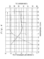
- Fig. 4 is a characteristic diagram showing the relationship of fan positioning to both flow amount variations within cooling medium passages and cooling medium flow amount in the embodiment;
- Fig. 5 is a characteristic diagram showing the relationship between fan length and flow amount variations between cooling medium passages in the embodiment;
- Figs. 6A and 6B show a conventional battery pack apparatus having a fan; where Fig. 6A is a plan view thereof and Fig. 6B is a longitudinal sectional front view showing the general configuration; and
- Fig. 7 is a longitudinal sectional side view of a battery pack apparatus conceived at a stage previous to development of the battery pack apparatus of the present invention.
- Hereinafter, an embodiment of a battery pack apparatus in accordance with the present invention will be described with reference to Figs. 1 to 5.
- In Figs. 1 through 4, a
battery pack apparatus 1 serves as a drive power source for an electric vehicle including hybrid vehicles, and contains abattery pack 5 composed of 10 to 30 flat prismaticrechargeable batteries 2 arranged in parallel withcooling medium passages 3 formed between the long side faces thereof, and being held between a pair ofend plates 4 disposed at both ends in the aligning direction, and secured as an integral unit by a binding member (not shown) Each of therechargeable batteries 2 is formed as a battery module including a plurality (6 in the shown example) ofcells 2a arranged in the lengthwise direction of the long side faces, thecells 2a being internally connected in series, andexternal connection terminals 2b projected at both ends. Thebattery pack 5 obtains a predetermined output voltage by successively connecting theconnection terminals 2b of therechargeable batteries 2 in series by bus bars (not shown) - Both ends of each of the
rechargeable batteries 2 of thebattery pack 5 are supported by support frames 6,6. A lower case 7 is disposed at a lower portion between the support frames 6,6. An inflow-end distribution space 8 is formed adjacent to a bottom side of thebattery pack 5 by the lower case 7 to supply cooling medium to each of thecooling medium passages 3. Also, thebattery pack 5 is covered by anupper case 9 at an upper portion of the support frames 6,6. An outflow-end distribution space 10 is projectingly formed adjacent to a top side of thebattery pack 5 by theupper case 9 to collect cooling medium which has flowed out from each of thecooling medium passages 3 and discharge it. A suction opening 10a for sucking cooling medium is formed on a top side of the outflow-end distribution space 10. - A
cross flow fan 11 is disposed on top of theupper case 9 with the axis thereof made to follow the aligning direction of therechargeable batteries 2. An intake port ha of thefan 11 is joined to the suction opening 10a of theupper case 9. Thefan 11 includes a substantiallytubular impeller 13 of a diameter D accommodated in afan case 12, and theimpeller 13 is disposed to be freely rotatable, and is rotated by amotor 14 linked to an end of its axis. Also, a stabilizer 15 is disposed at one side of the outer circumference of theimpeller 13. A combined discharge passage/intake chamber wall 18 extends downward at an inclination from an end of the stabilizer 15 to join to a circumferential edge of the suction opening 10a of theupper case 9. An upperair discharge passage 16 and a lower intake chamber 17 are thus formed. An opening at one end of anair discharge duct 19 is joined to adischarge opening 12a of thefan case 12 and an outer edge of the combined discharge passage/intake chamber wall 18. The intake chamber 17 is formed by both a portion lower than theimpeller 13 of thefan case 12 and the combined discharge passage/intake chamber wall 18, and a lower end opening thereof makes up theintake port 11a of thefan 11. - The position of the
axis 0 of thefan 11, with respect to a center line C of the outflow-end distribution space 10, the line in a perpendicular direction to the aligning direction of the rechargeable batteries, is eccentric by an amount x in the direction of movement of theimpeller 13 of thefan 11 at the intake chamber 17 side. The eccentricity amount x, with respect to the impeller diameter D of thefan 11, is set to satisfy 0 < x < 1.0D, and preferably, 0.2D < x < 0.5D. According to this embodiment, D is 60 mm, and x is from 12 mm to 30 mm. Also, a length s of the stabilizer 15 is from 1.5d to 5d, where d is a gap between the extremity of the stabilizer 15 and the outer circumference of theimpeller 13. - Also, as shown in Fig. 2, a length L in the aligning direction of the
rechargeable batteries 2 of thebattery pack 5 and a length F in the axial direction of theimpeller 13 are set so as to satisfy F ≥ L/2. The axis of thefan 11 is disposed to be perpendicular with respect to the coolingmedium passages 3. Also, the center of theimpeller 13 in the axial direction is substantially matched with the center of thebattery pack 5 in the aligning direction the rechargeable batteries. Specifically, thefan 11 is configured so as to satisfy y < L/n where y is a displacement amount of the center of theimpeller 13 with respect to the center of thebattery pack 5 is such that, L is the same as before, and n is the number of therechargeable batteries 2 of thebattery pack 5. That is, the displacement amount y is not larger than a thickness of therechargeable battery 2. - Also, as shown in Fig. 3, the
fan 11 is disposed such that the positions ofjunctures 13b in the axial direction ofvanes 13a of theimpeller 13 are offset from positions opposite to the coolingmedium passages 3 between therechargeable batteries - According to the discussed configuration, the
battery pack apparatus 1, which is compact in the aligning direction of therechargeable batteries 2 due to thefan 11 being disposed on the upper portion of thebattery pack 5, is compactly configured in the vertical direction as well. Thus, even though thefan 11 is disposed in proximity to the top side of thebattery pack 5, by disposing thecross flow fan 11 with the axis thereof following the aligning direction of therechargeable batteries 2, cooling medium is equally supplied to each of the coolingmedium passages 3 between therechargeable batteries fan 11 being eccentric in the direction of movement of theimpeller 13 at the intake chamber 17 side, the flow amount distribution of the cooling medium within each of the coolingmedium passages 3 is equalized without significantly decreasing the cooling medium flow amount. - That is, as shown in Fig. 4, with the eccentricity amount x at 0 mm or less, the flow amount dramatically declines and flow amount variations dramatically become large. Although not shown in Fig. 4, even when x is 60 mm or more, the flow amount dramatically declines and flow amount variations become large. In contrast, at 10 mm or more and 30 mm or less, flow amount variations are settled within an extremely small range of 6% or less, and flow amount is maintained at substantially 100%. Accordingly, by setting the eccentricity amount x so as to satisfy 0 < x < 1.0D, preferably 0.2D < x < 0.5D, flow amount distribution is equalized without decreasing flow amount.
- Also, the length s of the stabilizer 15 of the
fan 11 is set at from 1.5 to 5 times the gap d between the end of the stabilizer 15 and the outer circumference of theimpeller 13, and the combined discharge passage/intake chamber wall 18 is extended from the end of the stabilizer 15, and thus the capacity of the intake chamber 17 is enlarged into the region indicated with the diagonal hypothetical lines in Fig. 1. Thus, as has been discussed, even though the axis of thefan 11 is eccentric in the direction opposite to the stabilizer 15, flow rate decline at an end of the stabilizer 15 side within each of the coolingmedium passages 3 is restrained and variations of flow rate distribution is decreased, and, pressure loss is further decreased and cooling ability is increased and variations thereof is decreased. - Also, the length F of the
impeller 13 in the axial direction is set so as to satisfy F ≥ L/2, with respect to the length L of thebattery pack 5 in the aligning direction of therechargeable batteries 2. Thus, as shown in Fig. 5, even when thefan 11 is disposed in proximity to the top side of thebattery pack 5, cooling medium is equally supplied to each of the coolingmedium passages 3 without increasing flow amount variations between the coolingmedium passages 3. - Also, the
fan 11 is disposed such that the axis thereof is perpendicular with respect to the coolingmedium passages 3, and thus pressure loss is decreased and flow amount is large. Cooling ability is thereby improved. Also, thefan 11 is disposed so as to satisfy y < L/n, where y is the displacement amount of the center of theimpeller 13 in the axial direction with respect to the center of thebattery pack 5 in the aligning direction of the rechargeable batteries, L is the length of thebattery pack 5 in the aligning direction of the rechargeable batteries, and n is the number of therechargeable batteries 2. Thus, the cooling medium is equally supplied to the coolingmedium passages 3. - Also, the
fan 11 is disposed such that positions of thejunctures 13b in the axial direction of thevanes 13a of theimpeller 13 are offset from positions opposite to the coolingmedium passages 3, and thus flow rate of all of the coolingmedium passages 3 is equalized without being effected by thejunctures 13b of thevanes 13a. - Accordingly, while the
battery pack apparatus 1 is configured compactly by thecross flow fan 11 being disposed adjacent to one side face of thebattery pack 5, variations in SOC of therechargeable batteries 2 is restrained so as to improve the battery life due to an ability to uniformly cool therechargeable batteries 2. - According to a battery pack apparatus of the present invention, even though a fan is disposed in proximity to one side face of a battery pack, by disposing a cross flow fan such that the axis thereof follows the aligning direction of the rechargeable batteries, cooling medium is equally supplied to each of the cooling medium passages between the rechargeable batteries. Further, by the axial position of the fan being eccentric in the direction of movement of the impeller at a side of the one side face of the battery pack, flow amount distribution of the cooling medium within each of the cooling medium passages is equalized, and each of the rechargeable batteries are uniformly cooled within a compact configuration, and variations in SOC of the rechargeable batteries are restrained to improve the battery life.
Claims (9)
- A battery pack apparatus comprising:a battery pack including a plurality of rechargeable batteries arranged in parallel, the rechargeable batteries having cooling medium passages formed therebetween; anda cross flow fan disposed with an intake chamber facing a distribution space formed adjacent to one side face of the battery pack to supply or discharge a cooling medium to each of the cooling medium passages, the fan having an impeller disposed such that a rotational axis thereof follows an aligning direction of the rechargeable batteries,characterized in that an axial position of the fan is eccentric with respect to a center line of the distribution space perpendicular to the aligning direction of the rechargeable batteries in a direction of movement of the impeller at the distribution space side.
- A battery pack apparatus comprising:a battery pack including a plurality of rechargeable batteries arranged in parallel, the rechargeable batteries having cooling medium passages formed therebetween; anda cross flow fan disposed with an intake chamber facing a distribution space formed adjacent to one side face of the battery pack to supply or discharge a cooling medium to each of the cooling medium passages, the fan having an impeller disposed such that a rotational axis thereof follows an aligning direction of the rechargeable batteries,characterized in that a length of a stabilizer of the fan is from 1.5 to 5 times the size of a gap between an extremity of the stabilizer and the outer circumference of the impeller, and an intake chamber wall doubles as an air discharge passage wall or is adjacent to an air discharge passage wall.
- A battery pack apparatus comprising:a battery pack including a plurality of rechargeable batteries arranged in parallel, the rechargeable batteries having cooling medium passages formed therebetween; anda cross flow fan disposed with an intake chamber facing a distribution space formed adjacent to one side face of the battery pack to supply or discharge a cooling medium to each of the cooling medium passages, the fan having an impeller disposed such that a rotational axis thereof follows an aligning direction of the rechargeable batteries,characterized in that an axial position of the fan is eccentric with respect to a center line of the distribution space perpendicular to the aligning direction of the rechargeable batteries in a direction of movement of the impeller at the distribution space side, and
a length of a stabilizer of the fan is from 1.5 to 5 times the size of a gap between an extremity of the stabilizer and the outer circumference of the impeller, and an intake chamber wall doubles as an air discharge passage wall or is adjacent to an air discharge passage wall. - The battery pack apparatus according to claim 1 to 3, wherein
an eccentricity amount x of the axis of the fan with respect to a diameter D of the impeller is set to satisfy 0 < x < 1.0D. - The battery pack apparatus according to claim 1 to 3, wherein
an eccentricity amount x of the axis of the fan with respect to a diameter D of the impeller is set to satisfy 0.2D < x < 0.5D. - The battery pack apparatus according to any one of claims 1 to 3, wherein
the battery pack apparatus is configured to satisfy F ≥ L/2 where L is a length of the battery pack in the aligning direction of the rechargeable batteries and F is a length in the axial direction of the impeller. - The battery pack apparatus according to any one of claims 1 to 3, wherein
the axis of the fan is disposed to be perpendicular with respect to the cooling medium passages. - The battery pack apparatus according to any one of claims 1 to 3, wherein
the fan is disposed so as to satisfy y < L/n where y is a displacement amount of the center of the impeller in the axial direction with respect to the center of the battery pack in the aligning direction of the rechargeable batteries, L is a length of the battery pack in the aligning direction of the rechargeable batteries, and n is the number of the rechargeable batteries of the battery pack. - The battery pack apparatus according to any one of claims 1 to 3, wherein
the fan is disposed such that positions of junctures of vanes of the impeller in the axial direction are offset from positions opposite to the cooling medium passages.
Applications Claiming Priority (2)
| Application Number | Priority Date | Filing Date | Title |
|---|---|---|---|
| JP2003073435A JP4314044B2 (en) | 2003-03-18 | 2003-03-18 | Battery pack |
| JP2003073435 | 2003-03-18 |
Publications (3)
| Publication Number | Publication Date |
|---|---|
| EP1460699A2 true EP1460699A2 (en) | 2004-09-22 |
| EP1460699A3 EP1460699A3 (en) | 2005-07-27 |
| EP1460699B1 EP1460699B1 (en) | 2008-08-20 |
Family
ID=32821306
Family Applications (1)
| Application Number | Title | Priority Date | Filing Date |
|---|---|---|---|
| EP20040251480 Expired - Fee Related EP1460699B1 (en) | 2003-03-18 | 2004-03-15 | Battery pack cooling system |
Country Status (4)
| Country | Link |
|---|---|
| US (1) | US7199553B2 (en) |
| EP (1) | EP1460699B1 (en) |
| JP (1) | JP4314044B2 (en) |
| DE (1) | DE602004015874D1 (en) |
Cited By (2)
| Publication number | Priority date | Publication date | Assignee | Title |
|---|---|---|---|---|
| KR101054764B1 (en) | 2009-11-04 | 2011-08-05 | 현대자동차주식회사 | Operating temperature maintaining device of hybrid vehicle battery |
| KR101091665B1 (en) | 2009-10-23 | 2011-12-08 | 기아자동차주식회사 | Apparatus for cooling battery of hybrid electrical vehicle |
Families Citing this family (10)
| Publication number | Priority date | Publication date | Assignee | Title |
|---|---|---|---|---|
| JP5090070B2 (en) * | 2006-10-06 | 2012-12-05 | プライムアースEvエナジー株式会社 | Battery pack |
| KR100941266B1 (en) | 2007-12-13 | 2010-02-11 | 현대자동차일본기술연구소 | Battery unit with improved intake and exhaustion structure |
| JP5186955B2 (en) * | 2008-03-10 | 2013-04-24 | トヨタ自動車株式会社 | Power storage device |
| US9123944B2 (en) * | 2010-03-25 | 2015-09-01 | Ford Global Technologies, Llc | Battery cover assembly |
| US20110177379A1 (en) * | 2010-03-25 | 2011-07-21 | Ford Global Technologies, Llc | Battery assembly |
| US8323818B2 (en) * | 2010-03-25 | 2012-12-04 | Ford Global Technologies, Llc | Battery cooling |
| US20180191043A1 (en) * | 2017-01-03 | 2018-07-05 | Nec Energy Solutions, Inc. | System for Cooling Components Arranged within an Enclosure |
| CN106741549B (en) * | 2017-01-10 | 2022-07-05 | 浙江绿源电动车有限公司 | Dampproofing box subassembly and electric vehicle |
| KR20220114565A (en) | 2019-12-03 | 2022-08-17 | 밀워키 일렉트릭 툴 코포레이션 | Battery pack and charger system |
| CN113611954B (en) * | 2021-10-11 | 2021-12-07 | 湖南柠庆科技有限公司 | Be applied to vehicle's battery package installation mechanism |
Citations (6)
| Publication number | Priority date | Publication date | Assignee | Title |
|---|---|---|---|---|
| US5589290A (en) * | 1994-03-04 | 1996-12-31 | Deutsche Automobilgesellschaft Mbh | Battery box with fluid flow channels to maintain proper temperature |
| US5721064A (en) * | 1993-04-30 | 1998-02-24 | Aer Energy Resources Inc. | Air manager system for reducing gas concentrations in a metal-air battery |
| EP0920105A2 (en) * | 1997-11-25 | 1999-06-02 | Matsushita Electric Works, Ltd. | Charger |
| US6340877B1 (en) * | 1999-12-28 | 2002-01-22 | Honda Giken Kogyo Kabushiki Kaisha | Rechargeable cell support device with insulating rings |
| EP1174942A1 (en) * | 2000-07-17 | 2002-01-23 | Matsushita Electric Industrial Co., Ltd. | Power supply unit |
| EP1265309A2 (en) * | 2001-06-05 | 2002-12-11 | Matsushita Electric Industrial Co., Ltd. | Battery power supply device |
Family Cites Families (9)
| Publication number | Priority date | Publication date | Assignee | Title |
|---|---|---|---|---|
| JP2903913B2 (en) | 1992-11-10 | 1999-06-14 | 松下電器産業株式会社 | Storage battery system |
| US5560999A (en) | 1993-04-30 | 1996-10-01 | Aer Energy Resources, Inc. | Air manager system for recirculating reactant air in a metal-air battery |
| JP3450908B2 (en) * | 1994-09-21 | 2003-09-29 | 本田技研工業株式会社 | Battery cooling fan structure |
| JP4543464B2 (en) | 1999-12-09 | 2010-09-15 | トヨタ自動車株式会社 | Battery pack |
| JP2001167806A (en) * | 1999-12-09 | 2001-06-22 | Toyota Motor Corp | Battery pack for car |
| JP4961627B2 (en) * | 2000-07-24 | 2012-06-27 | トヨタ自動車株式会社 | Battery holder and battery pack |
| JP2002373709A (en) * | 2001-06-15 | 2002-12-26 | Denso Corp | Battery cooling structure |
| JP4272387B2 (en) * | 2002-05-22 | 2009-06-03 | パナソニック株式会社 | Battery pack cooling device |
| JP2004006089A (en) * | 2002-05-31 | 2004-01-08 | Toyota Motor Corp | Battery system |
-
2003
- 2003-03-18 JP JP2003073435A patent/JP4314044B2/en not_active Expired - Fee Related
-
2004
- 2004-03-15 EP EP20040251480 patent/EP1460699B1/en not_active Expired - Fee Related
- 2004-03-15 DE DE200460015874 patent/DE602004015874D1/en not_active Expired - Lifetime
- 2004-03-16 US US10/800,682 patent/US7199553B2/en not_active Expired - Fee Related
Patent Citations (6)
| Publication number | Priority date | Publication date | Assignee | Title |
|---|---|---|---|---|
| US5721064A (en) * | 1993-04-30 | 1998-02-24 | Aer Energy Resources Inc. | Air manager system for reducing gas concentrations in a metal-air battery |
| US5589290A (en) * | 1994-03-04 | 1996-12-31 | Deutsche Automobilgesellschaft Mbh | Battery box with fluid flow channels to maintain proper temperature |
| EP0920105A2 (en) * | 1997-11-25 | 1999-06-02 | Matsushita Electric Works, Ltd. | Charger |
| US6340877B1 (en) * | 1999-12-28 | 2002-01-22 | Honda Giken Kogyo Kabushiki Kaisha | Rechargeable cell support device with insulating rings |
| EP1174942A1 (en) * | 2000-07-17 | 2002-01-23 | Matsushita Electric Industrial Co., Ltd. | Power supply unit |
| EP1265309A2 (en) * | 2001-06-05 | 2002-12-11 | Matsushita Electric Industrial Co., Ltd. | Battery power supply device |
Cited By (2)
| Publication number | Priority date | Publication date | Assignee | Title |
|---|---|---|---|---|
| KR101091665B1 (en) | 2009-10-23 | 2011-12-08 | 기아자동차주식회사 | Apparatus for cooling battery of hybrid electrical vehicle |
| KR101054764B1 (en) | 2009-11-04 | 2011-08-05 | 현대자동차주식회사 | Operating temperature maintaining device of hybrid vehicle battery |
Also Published As
| Publication number | Publication date |
|---|---|
| EP1460699B1 (en) | 2008-08-20 |
| JP2004281298A (en) | 2004-10-07 |
| DE602004015874D1 (en) | 2008-10-02 |
| US20040183504A1 (en) | 2004-09-23 |
| JP4314044B2 (en) | 2009-08-12 |
| EP1460699A3 (en) | 2005-07-27 |
| US7199553B2 (en) | 2007-04-03 |
Similar Documents
| Publication | Publication Date | Title |
|---|---|---|
| JP5255817B2 (en) | Battery module | |
| EP1460699A2 (en) | Battery pack cooling system | |
| JP4827558B2 (en) | Power supply for vehicle | |
| JP4928057B2 (en) | Fluid-cooled battery pack system | |
| JP4592469B2 (en) | Assembled battery | |
| JP4046463B2 (en) | Power supply | |
| CN1319185C (en) | Combined battery and battery holding frame | |
| JP4625755B2 (en) | Secondary battery module | |
| KR100648704B1 (en) | Secondary battery module | |
| JP5526289B2 (en) | Battery pack with new structure | |
| EP1265309A2 (en) | Battery power supply device | |
| WO2017122690A1 (en) | Battery pack temperature control/power feed system | |
| CN100500466C (en) | Automatic management method for air filter used in battery pack | |
| JP2006156405A (en) | Secondary battery module | |
| JP2006128124A (en) | Secondary battery module | |
| JP6256439B2 (en) | Battery pack | |
| JP4024021B2 (en) | Power supply | |
| JP2004296217A (en) | Battery pack | |
| KR100684760B1 (en) | Secondary battery module | |
| JP2007234371A (en) | Power supply device for vehicle | |
| JP2011044275A (en) | Power supply device, and vehicle using the same | |
| JP4293980B2 (en) | Power supply for vehicle | |
| JP2004158393A (en) | Battery cooling device for automobile | |
| JP4484653B2 (en) | Power supply | |
| JP2009056816A (en) | Electric vehicle |
Legal Events
| Date | Code | Title | Description |
|---|---|---|---|
| PUAI | Public reference made under article 153(3) epc to a published international application that has entered the european phase |
Free format text: ORIGINAL CODE: 0009012 |
|
| AK | Designated contracting states |
Kind code of ref document: A2 Designated state(s): AT BE BG CH CY CZ DE DK EE ES FI FR GB GR HU IE IT LI LU MC NL PL PT RO SE SI SK TR |
|
| AX | Request for extension of the european patent |
Extension state: AL HR LT LV MK |
|
| PUAL | Search report despatched |
Free format text: ORIGINAL CODE: 0009013 |
|
| AK | Designated contracting states |
Kind code of ref document: A3 Designated state(s): AT BE BG CH CY CZ DE DK EE ES FI FR GB GR HU IE IT LI LU MC NL PL PT RO SE SI SK TR |
|
| AX | Request for extension of the european patent |
Extension state: AL LT LV MK |
|
| 17P | Request for examination filed |
Effective date: 20060102 |
|
| AKX | Designation fees paid |
Designated state(s): DE FR GB |
|
| 17Q | First examination report despatched |
Effective date: 20060906 |
|
| GRAP | Despatch of communication of intention to grant a patent |
Free format text: ORIGINAL CODE: EPIDOSNIGR1 |
|
| GRAS | Grant fee paid |
Free format text: ORIGINAL CODE: EPIDOSNIGR3 |
|
| GRAA | (expected) grant |
Free format text: ORIGINAL CODE: 0009210 |
|
| AK | Designated contracting states |
Kind code of ref document: B1 Designated state(s): DE FR GB |
|
| REG | Reference to a national code |
Ref country code: GB Ref legal event code: FG4D |
|
| REF | Corresponds to: |
Ref document number: 602004015874 Country of ref document: DE Date of ref document: 20081002 Kind code of ref document: P |
|
| PLBE | No opposition filed within time limit |
Free format text: ORIGINAL CODE: 0009261 |
|
| STAA | Information on the status of an ep patent application or granted ep patent |
Free format text: STATUS: NO OPPOSITION FILED WITHIN TIME LIMIT |
|
| 26N | No opposition filed |
Effective date: 20090525 |
|
| REG | Reference to a national code |
Ref country code: FR Ref legal event code: PLFP Year of fee payment: 12 |
|
| PGFP | Annual fee paid to national office [announced via postgrant information from national office to epo] |
Ref country code: DE Payment date: 20150326 Year of fee payment: 12 |
|
| PGFP | Annual fee paid to national office [announced via postgrant information from national office to epo] |
Ref country code: FR Payment date: 20150319 Year of fee payment: 12 Ref country code: GB Payment date: 20150324 Year of fee payment: 12 |
|
| REG | Reference to a national code |
Ref country code: DE Ref legal event code: R119 Ref document number: 602004015874 Country of ref document: DE |
|
| GBPC | Gb: european patent ceased through non-payment of renewal fee |
Effective date: 20160315 |
|
| REG | Reference to a national code |
Ref country code: FR Ref legal event code: ST Effective date: 20161130 |
|
| PG25 | Lapsed in a contracting state [announced via postgrant information from national office to epo] |
Ref country code: FR Free format text: LAPSE BECAUSE OF NON-PAYMENT OF DUE FEES Effective date: 20160331 Ref country code: DE Free format text: LAPSE BECAUSE OF NON-PAYMENT OF DUE FEES Effective date: 20161001 Ref country code: GB Free format text: LAPSE BECAUSE OF NON-PAYMENT OF DUE FEES Effective date: 20160315 |