EP1459035B1 - Method for determining corresponding points in stereoscopic three-dimensional measurements - Google Patents
Method for determining corresponding points in stereoscopic three-dimensional measurements Download PDFInfo
- Publication number
- EP1459035B1 EP1459035B1 EP02803416.3A EP02803416A EP1459035B1 EP 1459035 B1 EP1459035 B1 EP 1459035B1 EP 02803416 A EP02803416 A EP 02803416A EP 1459035 B1 EP1459035 B1 EP 1459035B1
- Authority
- EP
- European Patent Office
- Prior art keywords
- points
- point
- cameras
- actual
- dimensional
- Prior art date
- Legal status (The legal status is an assumption and is not a legal conclusion. Google has not performed a legal analysis and makes no representation as to the accuracy of the status listed.)
- Expired - Lifetime
Links
Images
Classifications
-
- G—PHYSICS
- G06—COMPUTING; CALCULATING OR COUNTING
- G06T—IMAGE DATA PROCESSING OR GENERATION, IN GENERAL
- G06T7/00—Image analysis
- G06T7/60—Analysis of geometric attributes
-
- G—PHYSICS
- G01—MEASURING; TESTING
- G01B—MEASURING LENGTH, THICKNESS OR SIMILAR LINEAR DIMENSIONS; MEASURING ANGLES; MEASURING AREAS; MEASURING IRREGULARITIES OF SURFACES OR CONTOURS
- G01B11/00—Measuring arrangements characterised by the use of optical techniques
- G01B11/24—Measuring arrangements characterised by the use of optical techniques for measuring contours or curvatures
-
- G—PHYSICS
- G06—COMPUTING; CALCULATING OR COUNTING
- G06T—IMAGE DATA PROCESSING OR GENERATION, IN GENERAL
- G06T7/00—Image analysis
- G06T7/50—Depth or shape recovery
- G06T7/55—Depth or shape recovery from multiple images
- G06T7/593—Depth or shape recovery from multiple images from stereo images
-
- G—PHYSICS
- G06—COMPUTING; CALCULATING OR COUNTING
- G06T—IMAGE DATA PROCESSING OR GENERATION, IN GENERAL
- G06T7/00—Image analysis
- G06T7/70—Determining position or orientation of objects or cameras
-
- G—PHYSICS
- G06—COMPUTING; CALCULATING OR COUNTING
- G06T—IMAGE DATA PROCESSING OR GENERATION, IN GENERAL
- G06T7/00—Image analysis
- G06T7/97—Determining parameters from multiple pictures
Definitions
- the present invention relates to three-dimensional measurement.
- the present invention concerns a method for finding corresponding points in a set of points imaged by different cameras.
- Computer vision systems are based on information obtained from various measuring devices.
- Information can be measured using e.g. a laser device, a measuring head or via recognition from an image.
- the information obtained can be utilized e.g. in quality control systems, where, on the basis of this information, it is possible to determine e.g. the correctness of shape of an object, coloring errors or the number of knots in sawn timber.
- a computer vision system is generally formed from cameras.
- Traditional computer vision systems comprised only one camera, which took a picture of the object. By processing the picture, various conclusions could be drawn from it.
- By using different algorithms it is possible to distinguish different levels in images on the basis of their border lines.
- the border lines are identified on the basis of intensity conversion.
- Another method of recognizing shapes in an image is to connect it to masks and filters so that only certain types of points will be distinguished from the image. The patterns formed by the points in the image can be compared to models in a database and thus recognized.
- a truly three-dimensional computer vision system therefore comprises several cameras.
- the points are usually formed on the surface of the object via illumination.
- the illumination is typically implemented using a laser.
- the point is imaged by cameras calibrated in the same coordinate system with the illuminating device, a laser pointer.
- the same points imaged by different cameras are called corresponding points.
- a number of points are measured.
- the set of points thus formed is called a point cloud.
- point clouds have been formed by illuminating one point at a time, in which case there are no problems regarding recognition of the corresponding point.
- they are all able to associate the measured data with the same point. Measuring one point at a time means that the pointer has to be moved every time between points, which is why this measuring method is slow.
- Patent publication US 4 834 530 A discloses a prior art method wherein in the steps mentioned in the preamble of the independent claim are described.
- the object of the invention is to eliminate the above-mentioned drawbacks or at least to significantly alleviate them.
- a specific object of the invention is to disclose a new type of method for connecting corresponding points.
- a further object of the invention is to improve the reliability of measurement and to accelerate the measuring process by enabling the use of a plurality of simultaneous points.
- corresponding points in a set of illuminated points can be connected by a computer vision system.
- the illuminator need not be moved as often as in the traditional solution, in which only one point at a time was illuminated.
- the total time spent on the measurement of the object is reduced considerably.
- reliability of measurement is improved because a definitely correct and the same point of each camera image is used to determine the coordinates of the measured point.
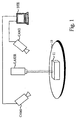
- the system illustrated in Fig. 1 comprises two cameras CAM1 and CAM2, an illuminator LASER and a data system DTE.
- An object 11 to be measured is placed on a support plate 10.
- the orientational position of the measuring object 11 is first determined on the basis of the three-dimensional shapes of the object. After the orientational position has been determined, points or areas to be measured are selected on the three-dimensional model of the object. Once the points have been selected, the data system DTE moves the illuminator LASER to the desired position to illuminate the set of points.
- the illuminator LASER By means of the illuminator LASER, points at desired positions are illuminated.
- the illuminator typically used is a laser. Using one or more laser beams, a number of light points are formed to illuminate the object. Instead of a laser, it is also possible to use other illuminating methods applicable for forming points on the object surface that are visible to a camera.
- the points illuminated by the illuminator can be shifted by physically moving the illuminator.
- the illuminated points are typically shifted by directing the beams via movable mirrors. When the mirrors are moved, the positions of the points change although the illuminator remains stationary. This improves the reliability of the system as the position of the illuminator remains unchanged and known.
- the illuminated points are imaged by cameras CAM1 and CAM2 calibrated in the same coordinate system with the illuminator. Typically, at least four cameras are used, but even using only two cameras it is possible to measure three-dimensional coordinates. When necessary, the number of cameras can be increased.
- the images taken by the cameras CAM1 and CAM2 are compared to projections formed from the three-dimensional model.
- a projection image is a two-dimensional picture representing the object, calculated by the data system DTE from the three-dimensional model of the object as seen from the direction of the camera.
- the positions of the illuminated points in the projection image are also calculated. From the positions of the points in the projection image, the connection between the cameras CAM1 and CAM2 and the points in the images can also be inferred.
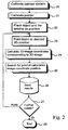
- Fig. 2 presents a function diagram of the system illustrated in Fig. 1 .
- a measurement procedure is started by calibrating the cameras of the system to the same coordinate system, step 20.
- the illuminator used to illuminate points on the surface of the object have to be calibrated as well, step 21.
- the preparations for measurement include determination of the position of the object, step 22.
- the position of the object placed on the support plate can be determined on the basis of its known three-dimensional shapes. Instead of the determination of position, the object can also be fastened to a predetermined location.
- Actual measurement is started by illuminating points at desired locations, step 23.
- the desired locations are selected by the data system, which gives instructions for moving the illuminator.
- the desired locations can be stored as sequences in the memory of the data system, in which case the same locations are measured on each object.
- various conditions can be set as criteria on the basis of which the decisions regarding measuring positions or termination of measurement are made.
- the measurement can be stopped e.g. after a predetermined number of points have been measured on the object.
- step 24 To allow the position of a point to be determined from the image taken by a camera, the coordinates of the point have to be converted into two-dimensional form, step 24. This is done by calculating from the three-dimensional model a projection image, in which the object is presented two-dimensionally from the direction of the camera. Two-dimensional coordinates of the point can be calculated from the projection image. This is repeated for all cameras in the system.
- a search is carried out to locate the points in the images taken by the cameras, step 25.
- a certain area e.g. a window or circle, is formed around the point, whereupon this area is searched to locate the point.
- the size of the area is defined beforehand.
- the point thus found in the image can be connected to the calculated point in the projection image.
- the points thus established constitute a pair of corresponding points, from which the actual three-dimensional coordinates of the point are computed. This is repeated for all points illuminated by the illuminator.
- the measured actual three-dimensional coordinates are stored into the memory of the data system, step 26. After this, a check is performed to determine whether it is necessary to measure further points, step 27. If the points have to be shifted to measure additional points, then the procedure is resumed at step 23. Otherwise the measurement is terminated, step 28.
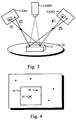
- Fig. 3 visualizes the operation of the system 1 presented in Fig. 1 .
- points are illuminated on the surface of an object 31 by an illuminator LASER.
- cameras CAM1 and CAM2 are represented as the images produced by them.
- projections are calculated for both cameras from the three-dimensional model of the object 31. From the projection images, the position of the selected point can be calculated with reasonable accuracy, because typically the deviation of shape between the object to be measured and the designed model is small.
- This point is reflected to the cameras CAM1 and CAM2 as shown by vector K1.
- the illuminator LASER produces a matrix illuminating several points simultaneously, other points are also visible in the images. In Fig. 3 , such a point is reflected to the cameras as shown by vector K2.
- Fig. 4 represents a perception as imaged by the camera.
- a point 41 is calculated and an area around it is searched to locate the actual point.
- the calculated points in the projection images can be connected to each other.
- the area to be searched is defined as an area 42 of square shape.
- the search area may be of any shape.
- the actual point 40 is detected, and this point can be connected to a point on the three-dimensional model by the aid of the calculated point in the projection image.
Description
- The present invention relates to three-dimensional measurement. The present invention concerns a method for finding corresponding points in a set of points imaged by different cameras.
- Computer vision systems are based on information obtained from various measuring devices. Information can be measured using e.g. a laser device, a measuring head or via recognition from an image. The information obtained can be utilized e.g. in quality control systems, where, on the basis of this information, it is possible to determine e.g. the correctness of shape of an object, coloring errors or the number of knots in sawn timber.
- A computer vision system is generally formed from cameras. Traditional computer vision systems comprised only one camera, which took a picture of the object. By processing the picture, various conclusions could be drawn from it. By using different algorithms, it is possible to distinguish different levels in images on the basis of their border lines. The border lines are identified on the basis of intensity conversion. Another method of recognizing shapes in an image is to connect it to masks and filters so that only certain types of points will be distinguished from the image. The patterns formed by the points in the image can be compared to models in a database and thus recognized.
- In a three-dimensional computer vision system, several cameras are used. To determine a three-dimensional coordinate, an image of the same point is needed from at least two cameras. A truly three-dimensional computer vision system therefore comprises several cameras. The points are usually formed on the surface of the object via illumination. The illumination is typically implemented using a laser. The point is imaged by cameras calibrated in the same coordinate system with the illuminating device, a laser pointer. The same points imaged by different cameras are called corresponding points. When an image of the point can be produced by at least two cameras and corresponding points can be identified, then it is possible to determine three-dimensional coordinates for the point. For the same position, a number of points are measured. The set of points thus formed is called a point cloud.
- In earlier methods, point clouds have been formed by illuminating one point at a time, in which case there are no problems regarding recognition of the corresponding point. When only one point on the object surface is visible to the cameras, they are all able to associate the measured data with the same point. Measuring one point at a time means that the pointer has to be moved every time between points, which is why this measuring method is slow.
- Patent publication
US 4 834 530 A discloses a prior art method wherein in the steps mentioned in the preamble of the independent claim are described. - Measurement methods using several cameras and light projection are also described in
JP10073419 A JP10283473 A - In
US6173 070 B1 , the 3D captured image data is searched for a predefined synthetic model which is similar in shape to the objects of interest. - In
US5532816 A , a signal representative of the rotational plane of a wheel is compared with an electronically stored mathematical model to determine wheel alignment conditions. - The object of the invention is to eliminate the above-mentioned drawbacks or at least to significantly alleviate them. A specific object of the invention is to disclose a new type of method for connecting corresponding points. A further object of the invention is to improve the reliability of measurement and to accelerate the measuring process by enabling the use of a plurality of simultaneous points.
- The objective according to the invention is achieved by a method comprising the features of claim 1.
- By applying the invention, corresponding points in a set of illuminated points can be connected by a computer vision system. As a benefit of this, the illuminator need not be moved as often as in the traditional solution, in which only one point at a time was illuminated. As a plurality of points can be measured at once, the total time spent on the measurement of the object is reduced considerably. In addition, reliability of measurement is improved because a definitely correct and the same point of each camera image is used to determine the coordinates of the measured point.
- In the following, the invention will be described in detail by the aid of embodiment examples with reference to the attached drawings, wherein
-
Fig. 1 presents an embodiment of the method of the invention, -
Fig. 2 presents a function diagram representing an embodiment of the method of the invention, -
Fig. 3 visualizes the operation of the embodiment illustrated inFig. 1 , and -
Fig. 4 is a more detailed illustration of the process of determining a corresponding point from information imaged by a camera. - The system illustrated in
Fig. 1 comprises two cameras CAM1 and CAM2, an illuminator LASER and a data system DTE. Anobject 11 to be measured is placed on asupport plate 10. - When the system of
Fig. 1 is used, the orientational position of themeasuring object 11 is first determined on the basis of the three-dimensional shapes of the object. After the orientational position has been determined, points or areas to be measured are selected on the three-dimensional model of the object. Once the points have been selected, the data system DTE moves the illuminator LASER to the desired position to illuminate the set of points. - By means of the illuminator LASER, points at desired positions are illuminated. The illuminator typically used is a laser. Using one or more laser beams, a number of light points are formed to illuminate the object. Instead of a laser, it is also possible to use other illuminating methods applicable for forming points on the object surface that are visible to a camera. The points illuminated by the illuminator can be shifted by physically moving the illuminator. The illuminated points are typically shifted by directing the beams via movable mirrors. When the mirrors are moved, the positions of the points change although the illuminator remains stationary. This improves the reliability of the system as the position of the illuminator remains unchanged and known.
- The illuminated points are imaged by cameras CAM1 and CAM2 calibrated in the same coordinate system with the illuminator. Typically, at least four cameras are used, but even using only two cameras it is possible to measure three-dimensional coordinates. When necessary, the number of cameras can be increased. The images taken by the cameras CAM1 and CAM2 are compared to projections formed from the three-dimensional model. A projection image is a two-dimensional picture representing the object, calculated by the data system DTE from the three-dimensional model of the object as seen from the direction of the camera. The positions of the illuminated points in the projection image are also calculated. From the positions of the points in the projection image, the connection between the cameras CAM1 and CAM2 and the points in the images can also be inferred.
-
Fig. 2 presents a function diagram of the system illustrated inFig. 1 . A measurement procedure is started by calibrating the cameras of the system to the same coordinate system,step 20. In addition to the cameras, the illuminator used to illuminate points on the surface of the object have to be calibrated as well, step 21. Besides calibration, the preparations for measurement include determination of the position of the object,step 22. The position of the object placed on the support plate can be determined on the basis of its known three-dimensional shapes. Instead of the determination of position, the object can also be fastened to a predetermined location. - Actual measurement is started by illuminating points at desired locations,
step 23. The desired locations are selected by the data system, which gives instructions for moving the illuminator. The desired locations can be stored as sequences in the memory of the data system, in which case the same locations are measured on each object. For the measurement, various conditions can be set as criteria on the basis of which the decisions regarding measuring positions or termination of measurement are made. The measurement can be stopped e.g. after a predetermined number of points have been measured on the object. - To allow the position of a point to be determined from the image taken by a camera, the coordinates of the point have to be converted into two-dimensional form,
step 24. This is done by calculating from the three-dimensional model a projection image, in which the object is presented two-dimensionally from the direction of the camera. Two-dimensional coordinates of the point can be calculated from the projection image. This is repeated for all cameras in the system. - On the basis of the two-dimensional coordinates picked up from the projection images, a search is carried out to locate the points in the images taken by the cameras,
step 25. A certain area, e.g. a window or circle, is formed around the point, whereupon this area is searched to locate the point. The size of the area is defined beforehand. The point thus found in the image can be connected to the calculated point in the projection image. The points thus established constitute a pair of corresponding points, from which the actual three-dimensional coordinates of the point are computed. This is repeated for all points illuminated by the illuminator. - The measured actual three-dimensional coordinates are stored into the memory of the data system,
step 26. After this, a check is performed to determine whether it is necessary to measure further points,step 27. If the points have to be shifted to measure additional points, then the procedure is resumed atstep 23. Otherwise the measurement is terminated,step 28. -
Fig. 3 visualizes the operation of the system 1 presented inFig. 1 . InFig. 3 , points are illuminated on the surface of anobject 31 by an illuminator LASER. In the figure, cameras CAM1 and CAM2 are represented as the images produced by them. By means of the data system, projections are calculated for both cameras from the three-dimensional model of theobject 31. From the projection images, the position of the selected point can be calculated with reasonable accuracy, because typically the deviation of shape between the object to be measured and the designed model is small. This point is reflected to the cameras CAM1 and CAM2 as shown by vector K1. As the illuminator LASER produces a matrix illuminating several points simultaneously, other points are also visible in the images. InFig. 3 , such a point is reflected to the cameras as shown by vector K2. - On the basis of the coordinates of the projection image, an area in which the point is to be searched for is selected in the images produced by the cameras CAM1 and CAM2.
Fig. 4 represents a perception as imaged by the camera. In the projection image, apoint 41 is calculated and an area around it is searched to locate the actual point. The calculated points in the projection images can be connected to each other. In the example, the area to be searched is defined as anarea 42 of square shape. However, the search area may be of any shape. In this area, theactual point 40 is detected, and this point can be connected to a point on the three-dimensional model by the aid of the calculated point in the projection image. Once the corresponding points have been determined, the actual three-dimensional coordinates of the point are calculated on the basis of them. - In
Fig. 4 , the difference betweenpoints - The invention is not limited to the embodiment examples described above; instead, many variations are possible within the scope of the appended claims.
Claims (9)
- Method for connecting corresponding points measured by a computer vision system in a set of points, said method comprising the steps of:calibrating at least two cameras (CAM1, CAM2) and an illuminator (LASER) used in the system (20, 21);determining the location and orientational position of the object (11, 22);illuminating points on the surface of the object (23);imaging the illuminated points by the at least two cameras (CAM1, CAM2);connecting corresponding points imaged by the at least two different cameras;calculating the actual three-dimensional coordinates of the object on the basis of the corresponding points; andstoring the coordinates in memory (26);characterized in that the step of connecting corresponding points further comprises the steps of:performing a calculation whereby two-dimensional projection points corresponding to the desired measuring points are determined in the images from a three-dimensional model of the object (24);searching an area near the calculated point in the images produced by the cameras to locate the actual point imaged (25);connecting the actual point perceived by the at least two different cameras as a corresponding point; andrepeating the procedure for all the illuminated points (27).
- Method according to claim 1, charac- terized in that the points to be measured are indicated by illuminating points at positions determined beforehand from the three-dimensional model of the object.
- Method according to claims 1 and 2, characterized in that the points are moved to measure the shapes of the object.
- Method according to claims 1 - 3, characterized in that the points are moved by moving the illuminator.
- Method according to claims 1 - 3, characterized in that the points are moved by directing the beams via movable mirrors.
- Method according to claim 1, characterized in that an area of predetermined size and shape around the calculated point is searched to locate the actual point.
- Method according to claims 1 and 6, characterized in that the predetermined area is a window.
- Method according to claim 1, characterized in that the points detected are connected as corresponding points by utilizing coordinate data regarding the points in the projection images.
- Method according to claims 1 and 8, characterized in that the actual three-dimensional coordinates of the point are calculated on the basis of the corresponding points detected.
Applications Claiming Priority (3)
| Application Number | Priority Date | Filing Date | Title |
|---|---|---|---|
| FI20012271 | 2001-11-21 | ||
| FI20012271A FI112279B (en) | 2001-11-21 | 2001-11-21 | Method for determining offset points |
| PCT/FI2002/000928 WO2003044460A1 (en) | 2001-11-21 | 2002-11-20 | Method for determining corresponding points in three-dimensional measurement |
Publications (2)
| Publication Number | Publication Date |
|---|---|
| EP1459035A1 EP1459035A1 (en) | 2004-09-22 |
| EP1459035B1 true EP1459035B1 (en) | 2016-08-31 |
Family
ID=8562309
Family Applications (1)
| Application Number | Title | Priority Date | Filing Date |
|---|---|---|---|
| EP02803416.3A Expired - Lifetime EP1459035B1 (en) | 2001-11-21 | 2002-11-20 | Method for determining corresponding points in stereoscopic three-dimensional measurements |
Country Status (7)
| Country | Link |
|---|---|
| US (1) | US7046377B2 (en) |
| EP (1) | EP1459035B1 (en) |
| JP (1) | JP4402458B2 (en) |
| AU (1) | AU2002366117A1 (en) |
| ES (1) | ES2605735T3 (en) |
| FI (1) | FI112279B (en) |
| WO (1) | WO2003044460A1 (en) |
Families Citing this family (19)
| Publication number | Priority date | Publication date | Assignee | Title |
|---|---|---|---|---|
| US7257248B2 (en) * | 2003-03-27 | 2007-08-14 | General Electric Company | Non-contact measurement system and method |
| EP2105698A1 (en) * | 2005-04-11 | 2009-09-30 | Faro Technologies, Inc. | Three-dimensional coordinate measuring device |
| US20070152157A1 (en) * | 2005-11-04 | 2007-07-05 | Raydon Corporation | Simulation arena entity tracking system |
| CN100385197C (en) * | 2006-06-08 | 2008-04-30 | 天津世纪动力光电科学仪器有限公司 | Portable railless-structured optical three-D scanning measuring system and measuring method therefor |
| US20080306708A1 (en) * | 2007-06-05 | 2008-12-11 | Raydon Corporation | System and method for orientation and location calibration for image sensors |
| FI123049B (en) * | 2007-09-03 | 2012-10-15 | Mapvision Ltd Oy | Recording Machine Vision System |
| US20110292406A1 (en) * | 2008-10-28 | 2011-12-01 | 3Shape A/S | Scanner with feedback control |
| CN102126162B (en) * | 2010-12-26 | 2013-09-25 | 北京航空航天大学 | Numerical control machine processing online measurement method |
| CN102135417B (en) * | 2010-12-26 | 2013-05-22 | 北京航空航天大学 | Full-automatic three-dimension characteristic extracting method |
| CN102722886B (en) * | 2012-05-21 | 2015-12-09 | 浙江捷尚视觉科技股份有限公司 | A kind of video frequency speed-measuring method based on three-dimensional scaling and Feature Points Matching |
| CN102944191B (en) * | 2012-11-28 | 2015-06-10 | 北京航空航天大学 | Method and device for three-dimensional vision measurement data registration based on planar circle target |
| CN103528520B (en) * | 2013-10-08 | 2016-03-23 | 哈尔滨工业大学 | Based on pick-up unit and the method for the synchronous operation jack-up system of binocular vision |
| CN105739339A (en) * | 2016-03-18 | 2016-07-06 | 上海斐讯数据通信技术有限公司 | Human body identification and locating method and system |
| CN106841206B (en) * | 2016-12-19 | 2018-07-24 | 大连理工大学 | Untouched online inspection method is cut in heavy parts chemical milling |
| CN108748137B (en) * | 2018-04-11 | 2021-02-02 | 陈小龙 | Material object scanning modeling method and application thereof |
| FR3082934B1 (en) * | 2018-06-26 | 2021-10-08 | Safran Nacelles | LASER PROJECTION DEVICE AND METHOD FOR MANUFACTURING PARTS FROM COMPOSITE MATERIAL BY DRAPING |
| CN110702025B (en) * | 2019-05-30 | 2021-03-19 | 北京航空航天大学 | Grating type binocular stereoscopic vision three-dimensional measurement system and method |
| CN111578866B (en) * | 2020-06-16 | 2021-04-20 | 大连理工大学 | Spatial pose calibration method for multi-line laser sensor combined measurement |
| CN114782434B (en) * | 2022-06-20 | 2022-09-27 | 青岛大学附属医院 | Endoscope cooperative target positioning method and system |
Citations (1)
| Publication number | Priority date | Publication date | Assignee | Title |
|---|---|---|---|---|
| US5532816A (en) * | 1994-03-15 | 1996-07-02 | Stellar Industries, Inc. | Laser tracking wheel alignment measurement apparatus and method |
Family Cites Families (20)
| Publication number | Priority date | Publication date | Assignee | Title |
|---|---|---|---|---|
| US4188544A (en) * | 1977-08-22 | 1980-02-12 | Weyerhaeuser Company | Method and apparatus for automatically processing a workpiece employing calibrated scanning |
| US4294544A (en) * | 1979-08-03 | 1981-10-13 | Altschuler Bruce R | Topographic comparator |
| GB2157826A (en) | 1984-04-17 | 1985-10-30 | Carves Simon Ltd | A surface topography measuring system |
| JPH0726828B2 (en) * | 1986-04-18 | 1995-03-29 | 株式会社トプコン | Shape measuring device |
| FR2629198B1 (en) | 1988-03-25 | 1994-07-08 | Kreon Ingenierie Marketing | METHOD FOR DETERMINING AND RECONSTRUCTING THE SPATIAL COORDINATES OF EACH POINT OF A SET OF POINTS SAMPLING A THREE-DIMENSIONAL SURFACE, AND METHOD FOR PRODUCING A THREE-DIMENSIONAL IMAGE OF THIS SURFACE FROM COORDINATE DETAILS |
| JPH02110789A (en) * | 1988-10-20 | 1990-04-23 | Niigata Eng Co Ltd | Method for recognizing shape of three-dimensional object |
| US4979815A (en) * | 1989-02-17 | 1990-12-25 | Tsikos Constantine J | Laser range imaging system based on projective geometry |
| US5383013A (en) * | 1992-09-18 | 1995-01-17 | Nec Research Institute, Inc. | Stereoscopic computer vision system |
| US5388059A (en) * | 1992-12-30 | 1995-02-07 | University Of Maryland | Computer vision system for accurate monitoring of object pose |
| US6147760A (en) * | 1994-08-30 | 2000-11-14 | Geng; Zheng Jason | High speed three dimensional imaging method |
| JP3478606B2 (en) * | 1994-10-12 | 2003-12-15 | キヤノン株式会社 | Stereoscopic image display method and apparatus |
| US6122065A (en) * | 1996-08-12 | 2000-09-19 | Centre De Recherche Industrielle Du Quebec | Apparatus and method for detecting surface defects |
| JP3372014B2 (en) * | 1996-08-29 | 2003-01-27 | ダイハツ工業株式会社 | Missing parts inspection equipment for engine external parts |
| JPH10283473A (en) * | 1997-04-03 | 1998-10-23 | Sumitomo Electric Ind Ltd | Broken inspecting method and device in image processing |
| AU8472898A (en) | 1997-06-30 | 1999-01-19 | Semiconductor Technologies & Instruments, Inc. | Method and apparatus for inspecting a workpiece |
| US6173070B1 (en) * | 1997-12-30 | 2001-01-09 | Cognex Corporation | Machine vision method using search models to find features in three dimensional images |
| US6789039B1 (en) * | 2000-04-05 | 2004-09-07 | Microsoft Corporation | Relative range camera calibration |
| JP4089148B2 (en) * | 2000-10-17 | 2008-05-28 | 株式会社日立製作所 | Interpreting service method and interpreting service device |
| US6492651B2 (en) * | 2001-02-08 | 2002-12-10 | 3D Systems, Inc. | Surface scanning system for selective deposition modeling |
| US6868194B2 (en) * | 2001-12-19 | 2005-03-15 | General Electric Company | Method for the extraction of image features caused by structure light using image reconstruction |
-
2001
- 2001-11-21 FI FI20012271A patent/FI112279B/en not_active IP Right Cessation
-
2002
- 2002-11-20 AU AU2002366117A patent/AU2002366117A1/en not_active Abandoned
- 2002-11-20 EP EP02803416.3A patent/EP1459035B1/en not_active Expired - Lifetime
- 2002-11-20 JP JP2003546046A patent/JP4402458B2/en not_active Expired - Lifetime
- 2002-11-20 ES ES02803416.3T patent/ES2605735T3/en not_active Expired - Lifetime
- 2002-11-20 WO PCT/FI2002/000928 patent/WO2003044460A1/en active Application Filing
- 2002-11-20 US US10/496,144 patent/US7046377B2/en not_active Expired - Lifetime
Patent Citations (1)
| Publication number | Priority date | Publication date | Assignee | Title |
|---|---|---|---|---|
| US5532816A (en) * | 1994-03-15 | 1996-07-02 | Stellar Industries, Inc. | Laser tracking wheel alignment measurement apparatus and method |
Also Published As
| Publication number | Publication date |
|---|---|
| ES2605735T3 (en) | 2017-03-16 |
| US20050012056A1 (en) | 2005-01-20 |
| US7046377B2 (en) | 2006-05-16 |
| FI20012271A0 (en) | 2001-11-21 |
| FI112279B (en) | 2003-11-14 |
| FI20012271A (en) | 2003-05-22 |
| WO2003044460A1 (en) | 2003-05-30 |
| EP1459035A1 (en) | 2004-09-22 |
| JP2005509879A (en) | 2005-04-14 |
| JP4402458B2 (en) | 2010-01-20 |
| AU2002366117A1 (en) | 2003-06-10 |
Similar Documents
| Publication | Publication Date | Title |
|---|---|---|
| EP1459035B1 (en) | Method for determining corresponding points in stereoscopic three-dimensional measurements | |
| JP4221768B2 (en) | Method and apparatus for positioning an object in space | |
| Lindner et al. | Lateral and depth calibration of PMD-distance sensors | |
| KR101194936B1 (en) | Three-dimensional measurement apparatus and method thereof | |
| US7098435B2 (en) | Method and apparatus for scanning three-dimensional objects | |
| US7271377B2 (en) | Calibration ring for developing and aligning view dependent image maps with 3-D surface data | |
| US5832106A (en) | Method for camera calibration of range imaging system by use of neural network | |
| US20100245851A1 (en) | Method and apparatus for high-speed unconstrained three-dimensional digitalization | |
| US5889582A (en) | Image-directed active range finding system | |
| CN103649674A (en) | Measurement device and information processing device | |
| US7860298B2 (en) | Method and system for the calibration of a computer vision system | |
| JP2003130621A (en) | Method and system for measuring three-dimensional shape | |
| EP3049756B1 (en) | Modeling arrangement and method and system for modeling the topography of a three-dimensional surface | |
| JPH11166818A (en) | Calibrating method and device for three-dimensional shape measuring device | |
| JP7353757B2 (en) | Methods for measuring artifacts | |
| EP3975116B1 (en) | Detecting displacements and/or defects in a point cloud using cluster-based cloud-to-cloud comparison | |
| Bergström et al. | Automatic in-line inspection of shape based on photogrammetry | |
| US7046839B1 (en) | Techniques for photogrammetric systems | |
| El-Hakim | A hierarchical approach to stereo vision | |
| WO2003042924A1 (en) | Connection of point clouds measured by a computer vision system | |
| CN106123808B (en) | A method of it is measured for the deflection of automobile rearview mirror specular angle degree | |
| Uyanik et al. | A method for determining 3D surface points of objects by a single camera and rotary stage | |
| US20240077310A1 (en) | Laser scanner with stereo camera vision for improved selective feature scanning | |
| US11561088B2 (en) | Modeling the topography of a three-dimensional surface | |
| El-Hakim et al. | VCM automated 3D measurement system: theory, application, and performance evaluation |
Legal Events
| Date | Code | Title | Description |
|---|---|---|---|
| PUAI | Public reference made under article 153(3) epc to a published international application that has entered the european phase |
Free format text: ORIGINAL CODE: 0009012 |
|
| 17P | Request for examination filed |
Effective date: 20040618 |
|
| AK | Designated contracting states |
Kind code of ref document: A1 Designated state(s): AT BE BG CH CY CZ DE DK EE ES FI FR GB GR IE IT LI LU MC NL PT SE SK TR |
|
| AX | Request for extension of the european patent |
Extension state: AL LT LV MK RO SI |
|
| 17Q | First examination report despatched |
Effective date: 20100401 |
|
| GRAP | Despatch of communication of intention to grant a patent |
Free format text: ORIGINAL CODE: EPIDOSNIGR1 |
|
| INTG | Intention to grant announced |
Effective date: 20151127 |
|
| GRAP | Despatch of communication of intention to grant a patent |
Free format text: ORIGINAL CODE: EPIDOSNIGR1 |
|
| INTG | Intention to grant announced |
Effective date: 20160525 |
|
| GRAS | Grant fee paid |
Free format text: ORIGINAL CODE: EPIDOSNIGR3 |
|
| GRAA | (expected) grant |
Free format text: ORIGINAL CODE: 0009210 |
|
| AK | Designated contracting states |
Kind code of ref document: B1 Designated state(s): AT BE BG CH CY CZ DE DK EE ES FI FR GB GR IE IT LI LU MC NL PT SE SK TR |
|
| REG | Reference to a national code |
Ref country code: CH Ref legal event code: EP Ref country code: GB Ref legal event code: FG4D |
|
| REG | Reference to a national code |
Ref country code: DE Ref legal event code: R081 Ref document number: 60248317 Country of ref document: DE Owner name: OY MAPVISION LTD, FI Free format text: FORMER OWNER: MAPVISION OY LTD., ESPOO, FI |
|
| REG | Reference to a national code |
Ref country code: IE Ref legal event code: FG4D |
|
| REG | Reference to a national code |
Ref country code: DE Ref legal event code: R096 Ref document number: 60248317 Country of ref document: DE |
|
| REG | Reference to a national code |
Ref country code: AT Ref legal event code: REF Ref document number: 825386 Country of ref document: AT Kind code of ref document: T Effective date: 20161015 |
|
| RAP2 | Party data changed (patent owner data changed or rights of a patent transferred) |
Owner name: OY MAPVISION LTD |
|
| REG | Reference to a national code |
Ref country code: DE Ref legal event code: R081 Ref document number: 60248317 Country of ref document: DE Owner name: OY MAPVISION LTD, FI Free format text: FORMER OWNER: MAPVISION OY LTD., ESPOO, FI |
|
| REG | Reference to a national code |
Ref country code: FR Ref legal event code: PLFP Year of fee payment: 15 |
|
| REG | Reference to a national code |
Ref country code: SE Ref legal event code: TRGR |
|
| REG | Reference to a national code |
Ref country code: NL Ref legal event code: MP Effective date: 20160831 |
|
| REG | Reference to a national code |
Ref country code: AT Ref legal event code: MK05 Ref document number: 825386 Country of ref document: AT Kind code of ref document: T Effective date: 20160831 |
|
| PG25 | Lapsed in a contracting state [announced via postgrant information from national office to epo] |
Ref country code: FI Free format text: LAPSE BECAUSE OF FAILURE TO SUBMIT A TRANSLATION OF THE DESCRIPTION OR TO PAY THE FEE WITHIN THE PRESCRIBED TIME-LIMIT Effective date: 20160831 |
|
| PG25 | Lapsed in a contracting state [announced via postgrant information from national office to epo] |
Ref country code: NL Free format text: LAPSE BECAUSE OF FAILURE TO SUBMIT A TRANSLATION OF THE DESCRIPTION OR TO PAY THE FEE WITHIN THE PRESCRIBED TIME-LIMIT Effective date: 20160831 Ref country code: AT Free format text: LAPSE BECAUSE OF FAILURE TO SUBMIT A TRANSLATION OF THE DESCRIPTION OR TO PAY THE FEE WITHIN THE PRESCRIBED TIME-LIMIT Effective date: 20160831 Ref country code: BE Free format text: LAPSE BECAUSE OF NON-PAYMENT OF DUE FEES Effective date: 20161130 Ref country code: GR Free format text: LAPSE BECAUSE OF FAILURE TO SUBMIT A TRANSLATION OF THE DESCRIPTION OR TO PAY THE FEE WITHIN THE PRESCRIBED TIME-LIMIT Effective date: 20161201 |
|
| REG | Reference to a national code |
Ref country code: ES Ref legal event code: FG2A Ref document number: 2605735 Country of ref document: ES Kind code of ref document: T3 Effective date: 20170316 |
|
| PG25 | Lapsed in a contracting state [announced via postgrant information from national office to epo] |
Ref country code: EE Free format text: LAPSE BECAUSE OF FAILURE TO SUBMIT A TRANSLATION OF THE DESCRIPTION OR TO PAY THE FEE WITHIN THE PRESCRIBED TIME-LIMIT Effective date: 20160831 |
|
| PG25 | Lapsed in a contracting state [announced via postgrant information from national office to epo] |
Ref country code: PT Free format text: LAPSE BECAUSE OF FAILURE TO SUBMIT A TRANSLATION OF THE DESCRIPTION OR TO PAY THE FEE WITHIN THE PRESCRIBED TIME-LIMIT Effective date: 20170102 Ref country code: BE Free format text: LAPSE BECAUSE OF FAILURE TO SUBMIT A TRANSLATION OF THE DESCRIPTION OR TO PAY THE FEE WITHIN THE PRESCRIBED TIME-LIMIT Effective date: 20160831 Ref country code: BG Free format text: LAPSE BECAUSE OF FAILURE TO SUBMIT A TRANSLATION OF THE DESCRIPTION OR TO PAY THE FEE WITHIN THE PRESCRIBED TIME-LIMIT Effective date: 20161130 Ref country code: SK Free format text: LAPSE BECAUSE OF FAILURE TO SUBMIT A TRANSLATION OF THE DESCRIPTION OR TO PAY THE FEE WITHIN THE PRESCRIBED TIME-LIMIT Effective date: 20160831 Ref country code: DK Free format text: LAPSE BECAUSE OF FAILURE TO SUBMIT A TRANSLATION OF THE DESCRIPTION OR TO PAY THE FEE WITHIN THE PRESCRIBED TIME-LIMIT Effective date: 20160831 Ref country code: CZ Free format text: LAPSE BECAUSE OF FAILURE TO SUBMIT A TRANSLATION OF THE DESCRIPTION OR TO PAY THE FEE WITHIN THE PRESCRIBED TIME-LIMIT Effective date: 20160831 |
|
| REG | Reference to a national code |
Ref country code: DE Ref legal event code: R097 Ref document number: 60248317 Country of ref document: DE |
|
| REG | Reference to a national code |
Ref country code: CH Ref legal event code: PL |
|
| PLBE | No opposition filed within time limit |
Free format text: ORIGINAL CODE: 0009261 |
|
| STAA | Information on the status of an ep patent application or granted ep patent |
Free format text: STATUS: NO OPPOSITION FILED WITHIN TIME LIMIT |
|
| PG25 | Lapsed in a contracting state [announced via postgrant information from national office to epo] |
Ref country code: CH Free format text: LAPSE BECAUSE OF NON-PAYMENT OF DUE FEES Effective date: 20161130 Ref country code: LI Free format text: LAPSE BECAUSE OF NON-PAYMENT OF DUE FEES Effective date: 20161130 |
|
| 26N | No opposition filed |
Effective date: 20170601 |
|
| REG | Reference to a national code |
Ref country code: IE Ref legal event code: MM4A |
|
| PG25 | Lapsed in a contracting state [announced via postgrant information from national office to epo] |
Ref country code: LU Free format text: LAPSE BECAUSE OF NON-PAYMENT OF DUE FEES Effective date: 20161130 |
|
| REG | Reference to a national code |
Ref country code: FR Ref legal event code: PLFP Year of fee payment: 16 |
|
| PG25 | Lapsed in a contracting state [announced via postgrant information from national office to epo] |
Ref country code: IE Free format text: LAPSE BECAUSE OF NON-PAYMENT OF DUE FEES Effective date: 20161120 |
|
| PG25 | Lapsed in a contracting state [announced via postgrant information from national office to epo] |
Ref country code: CY Free format text: LAPSE BECAUSE OF FAILURE TO SUBMIT A TRANSLATION OF THE DESCRIPTION OR TO PAY THE FEE WITHIN THE PRESCRIBED TIME-LIMIT Effective date: 20160831 |
|
| PG25 | Lapsed in a contracting state [announced via postgrant information from national office to epo] |
Ref country code: TR Free format text: LAPSE BECAUSE OF FAILURE TO SUBMIT A TRANSLATION OF THE DESCRIPTION OR TO PAY THE FEE WITHIN THE PRESCRIBED TIME-LIMIT Effective date: 20160831 Ref country code: MC Free format text: LAPSE BECAUSE OF FAILURE TO SUBMIT A TRANSLATION OF THE DESCRIPTION OR TO PAY THE FEE WITHIN THE PRESCRIBED TIME-LIMIT Effective date: 20160831 |
|
| PGFP | Annual fee paid to national office [announced via postgrant information from national office to epo] |
Ref country code: SE Payment date: 20211122 Year of fee payment: 20 Ref country code: DE Payment date: 20211119 Year of fee payment: 20 Ref country code: GB Payment date: 20211118 Year of fee payment: 20 Ref country code: ES Payment date: 20211209 Year of fee payment: 20 Ref country code: FR Payment date: 20211118 Year of fee payment: 20 |
|
| PGFP | Annual fee paid to national office [announced via postgrant information from national office to epo] |
Ref country code: IT Payment date: 20211122 Year of fee payment: 20 |
|
| REG | Reference to a national code |
Ref country code: DE Ref legal event code: R071 Ref document number: 60248317 Country of ref document: DE |
|
| REG | Reference to a national code |
Ref country code: ES Ref legal event code: FD2A Effective date: 20221125 |
|
| REG | Reference to a national code |
Ref country code: GB Ref legal event code: PE20 Expiry date: 20221119 |
|
| REG | Reference to a national code |
Ref country code: SE Ref legal event code: EUG |
|
| PG25 | Lapsed in a contracting state [announced via postgrant information from national office to epo] |
Ref country code: GB Free format text: LAPSE BECAUSE OF EXPIRATION OF PROTECTION Effective date: 20221119 Ref country code: ES Free format text: LAPSE BECAUSE OF EXPIRATION OF PROTECTION Effective date: 20221121 |